ertms/etcs national values - rssb iss 1.pdf · issue record issue date comments one 02/09/2017...
TRANSCRIPT

Rail Industry StandardRIS-0708-CCSIssue: OneDate: September 2017
ERTMS/ETCS NationalValues
Synopsis
This document contains requirements andguidance for a process to determine orrevise a set of values of ERTMS/ETCSNational Values.
Copyright in the Railway Group documents is owned by RailSafety and Standards Board Limited. All rights are herebyreserved. No Railway Group document (in whole or in part)may be reproduced, stored in a retrieval system, ortransmitted, in any form or means, without the prior writtenpermission of Rail Safety and Standards Board Limited, or asexpressly permitted by law.
RSSB members are granted copyright licence in accordancewith the Constitution Agreement relating to Rail Safety andStandards Board Limited.
In circumstances where Rail Safety and Standards BoardLimited has granted a particular person or organisationpermission to copy extracts from Railway Group documents,Rail Safety and Standards Board Limited accepts noresponsibility for, nor any liability in connection with, the useof such extracts, or any claims arising therefrom. Thisdisclaimer applies to all forms of media in which extractsfrom Railway Group documents may be reproduced.
Published by RSSB
© Copyright 2017Rail Safety and Standards Board Limited
Uncontrolled when printed Document supersedes GERT8408 Iss 1 and GEGN8608 Iss 1 with effect from 02/09/2017

Issue Record
Issue Date Comments
One 02/09/2017 Original document. To include additional National Values fromERTMS Baseline 3
This document will be updated when necessary by distribution of a complete replacement.
Superseded Documents
The following Railway Group documents are superseded, either in whole or in part as indicated:
Superseded documents Sections superseded Date whensections aresuperseded
GERT8408 issue one ERTMS/ETCSNational Values
All 02/09/2017
GEGN8608 issue one Guidance onERTMS/ETCS National Values
All 02/09/2017
Supply
The authoritative version of this document is available at www.rssb.co.uk/railway-group-standards. Enquirieson this document can be forwarded to [email protected].
Rail Industry StandardRIS-0708-CCSIssue: OneDate: September 2017
ERTMS/ETCS National Values
Page 2 of 74 RSSB
Uncontrolled when printed Document supersedes GERT8408 Iss 1 and GEGN8608 Iss 1 with effect from 02/09/2017

Contents
Part 1 Purpose and Introduction 7
1.1 Purpose 71.2 Context 71.3 Application of this document 81.4 Health and safety responsibilities 81.5 Structure of this document 81.6 Approval and Authorisation 8
Part 2 Requirements for ERTMS/ETCS National Values 9
2.1 Proposal of a set of ERTMS/ETCS National Values 92.2 Consultation on the proposed ERTMS/ETCS National Values 92.3 Consultation response on the proposed ERTMS/ETCS National Values 102.4 Optimising National Values 102.5 Publishing National Values 10
Appendices 11Appendix A 11
Definitions 68References 74
ERTMS/ETCS National Values Rail Industry StandardRIS-0708-CCSIssue: OneDate: September 2017
RSSB Page 3 of 74
Uncontrolled when printed Document supersedes GERT8408 Iss 1 and GEGN8608 Iss 1 with effect from 02/09/2017

List of Figures
Figure 1: Confidence interval of a ETCS fitted train 33
Figure 2: Chart demonstrating, by simplifying the curves as straight lines as an example, the shape ofthe resultant Permitted speed curve 35
Figure 3: High level schematic diagram of the processing of braking curves 36
Figure 4: Schematic diagram of how braking curves are derived 38
Figure 5: Comparison of where the 'hook' is shown if GUI curve is enabled. 41
Figure 6: Comparison of the position of the 'hook' if Q_NVSBFBPERM is enabled 42
Figure 7: Comparison of the position of the 'hook' if Q_NVINHSMICPERM is enabled 44
Figure 8: Demonstration of how A_NVMAXREDADH derates EBD and increases braking distance 46
Figure 9: DMI with TI initiated 47
Figure 10: DMI with TTI initiated 48
Figure 11: An example of a four steps Kv_int 58
Figure 12: Four steps Kv_int models 58
Figure 13: Process of extracting Kv_int 61
Figure 14: An example of a set of M_KRINT correction factors with five steps 65
Rail Industry StandardRIS-0708-CCSIssue: OneDate: September 2017
ERTMS/ETCS National Values
Page 4 of 74 RSSB
Uncontrolled when printed Document supersedes GERT8408 Iss 1 and GEGN8608 Iss 1 with effect from 02/09/2017

List of Tables
Table 1: Q_NVDRIVER_ADHES 11
Table 2: V_NVSHUNT 13
Table 3: V_NVSTFF 13
Table 4: V_NVONSIGHT 14
Table 5: V_NVSUPOVTRP 14
Table 6: V_NVUNFIT 17
Table 7: V_NVLIMSUPERV 18
Table 8: V_NVREL 19
Table 9: D_NVROLL 20
Table 10: V_NVALLOWOVTRP 22
Table 11: D_NVOVTRP 23
Table 12: T_NVOVTRP 24
Table 13: M_NVDERUN 26
Table 14: M_NVCONTACT 27
Table 15: T_NVCONTACT 27
Table 16: D_NVPOTRP 29
Table 17: D_NVSTFF 31
Table 18: Q_NVLOCACC 32
Table 19: Q_NVGUIPERM 40
Table 20: Q_NVSBFBPERM 41
Table 21: Q_NVINHSMICPERM 43
Table 22: A_NVMAXREDADH1/2/3 45
Table 23: Q_NVSRBKTRG 49
Table 24: Q_NVSBTSMPERM 50
Table 25: Q_NVEMRRLS 50
Table 26: M_NVEBCL 52
Table 27: M_NVAVADH 54
ERTMS/ETCS National Values Rail Industry StandardRIS-0708-CCSIssue: OneDate: September 2017
RSSB Page 5 of 74
Uncontrolled when printed Document supersedes GERT8408 Iss 1 and GEGN8608 Iss 1 with effect from 02/09/2017

Table 28: V_NVKVINT 56
Table 29: Q_NVKVINTSET 56
Table 30: M_NVKVINT 57
Table 31: A_NVP12 59
Table 32: A_NVP23 60
Table 33: Comparison of how A_NVP12, A_NVP23, Kv_int_x_a and Kv_int_x_b affects the outcome(all values are in relative terms) 62
Table 34: L_NVKRINT 63
Table 35: M_NVKRINT 64
Table 36: M_NVKTINT 66
Rail Industry StandardRIS-0708-CCSIssue: OneDate: September 2017
ERTMS/ETCS National Values
Page 6 of 74 RSSB
Uncontrolled when printed Document supersedes GERT8408 Iss 1 and GEGN8608 Iss 1 with effect from 02/09/2017

Part 1 Purpose and Introduction
1.1 Purpose
1.1.1 This document is a standard on ERTMS/ETCS National Values, for members of RSSB to use if they sochoose.
1.1.2 This document contains requirements for a process to determine or revise European Rail TrafficManagement System (ERTMS) / European Train Control System (ETCS) National Values within a set.
1.1.3 Guidance is provided as a series of sequentially numbered clauses prefixed ‘G’ immediately beloweach requirement. Where there is no guidance, this is stated.
1.1.4 The process set out in this document is applicable to ETCS fitted infrastructure irrespective of whetheror not ERTMS-fitted trains operate on that infrastructure.
1.1.5 ERTMS/ETCS National Values, determined in accordance with the process set out in this document,describes asset characteristics that are relevant to compatibility between ERTMS-fitted trains and tracksideinfrastructure.
1.1.6 This standard is applicable to all three ETCS Baselines legal at the time of publication: Baseline 2,Baseline 3 Maintenance Release 1, and Baseline 3 Release 2, as specified in the Control Command andSignalling Technical Specification for Interoperability (CCS TSI).
1.1.7 Details on all the ERTMS/ETCS National Values are set out in the Appendix.
1.2 Context
1.2.1 ERTMS/ETCS National Values are parameters in the ETCS system, described in ERTMS subset-026,Systems Requirements Specification (SRS).
1.2.2 A set of ERTMS/ETCS National Values applies to a ‘National Area’. A National Area is a geographicregion and does not necessarily align to political borders. ‘National’ in this context means determined atthe national level, not necessarily applying throughout a whole nation.
1.2.3 The values are set as part of the infrastructure design to configure the behaviour of an ERTMS/ETCSapplication to be compatible with the operational and technical practices of a particular geographic region,for example, the maximum speeds permitted under different modes of operation.
1.2.4 National Values are configured by the infrastructure manager (IM) and coded within the tracksideinfrastructure, that is, Eurobalises and Radio Block Centres (RBCs). The values are sent to trains operating inthe geographic region to which they apply and they cause the ETCS onboard to function in a way consistentwith the infrastructure.
1.2.5 The SRS describes the National Values and details the range of values, it also specifies a default valuefor the ETCS onboard to use when the National Values for the geographic region that it is operating in arenot available. This information is replicated in the Appendix.
1.2.6 Because the ERTMS/ETCS National Values are part of the trackside design, an IM needs to determinea set of values that are suitable for a geographic region. By the nature of National Values, this will affectthe performance of ETCS fitted trains operating on that infrastructure. Therefore, it is consideredadvantageous to have an industry-agreed method of proposing, evaluating, agreeing and making availablenew sets, or revising existing sets, of National Values. This standard fulfils that purpose.
ERTMS/ETCS National Values Rail Industry StandardRIS-0708-CCSIssue: OneDate: September 2017
RSSB Page 7 of 74
Uncontrolled when printed Document supersedes GERT8408 Iss 1 and GEGN8608 Iss 1 with effect from 02/09/2017

1.2.7 This standard requires the IM who is introducing or revising the National Values to engage inconsultation with neighbouring IMs and RUs who may be affected by the new National Values. Theobjective is to achieve harmonised operational practices across geographic regions.
1.2.8 This standard does not recommend specific values as National Values, but it does provideinformation to assist in determining a set of values, or evaluating the impact of a set of values.
1.2.9 In determining or revising a set of values, an IM will need to apply its own processes to managesafety and this will need to consider trains operating with the default set of values when the correct set forthe geographic region is not available. Processes such as the Common Safety Method for Risk Evaluationand Assessment (CSM RA) will likely apply and the guidance in this standard will support these processes.
1.2.10 The CCS TSI requires that ETCS onboard equipment is compatible with any specific value of aNational Value within the permitted range; once placed into service it is possible that the train may receiveany permitted value of National Value during its lifetime.
1.3 Application of this document
1.3.1 Compliance requirements and dates have not been specified since these will be the subject of internalprocedures or contract conditions.
1.3.2 The Standards Manual and the Railway Group Standards (RGS) Code do not currently provide aformal process for deviating from a Rail Industry Standard (RIS). However, a member of RSSB, havingadopted a RIS and wishing to deviate from its requirements, may request a Standards Committee toprovide opinions and comments on their proposed alternative to the requirement in the RIS. Requests foropinions and comments should be submitted to RSSB by e-mail to [email protected]. Whenformulating a request, consideration should be given to the advice set out in the ‘Guidance to applicantsand members of Standards Committee on deviation applications’, available from RSSB’s website.
1.4 Health and safety responsibilities
1.4.1 Users of documents published by RSSB are reminded of the need to consider their own responsibilitiesto ensure health and safety at work and their own duties under health and safety legislation. RSSB does notwarrant that compliance with all or any documents published by RSSB as sufficient in itself to ensure safesystems of work or operation or to satisfy such responsibilities or duties.
1.5 Structure of this document
1.5.1 This document sets out a series of requirements that are sequentially numbered.
1.5.2 This document also sets out the rationale for the requirement. The rationale explains why therequirement is needed and its purpose. Rationale clauses are prefixed by the letter 'G'.
1.5.3 Where relevant, guidance supporting the requirement is also set out in this document by a series ofsequentially numbered clauses and is identified by the letter 'G'.
1.6 Approval and Authorisation
1.6.1 The content of this document was approved by the Control Command and Signalling StandardsCommittee on 13 April 2017.
1.6.2 This document was authorised by RSSB on 26 July 2017.
Rail Industry StandardRIS-0708-CCSIssue: OneDate: September 2017
ERTMS/ETCS National Values
Page 8 of 74 RSSB
Uncontrolled when printed Document supersedes GERT8408 Iss 1 and GEGN8608 Iss 1 with effect from 02/09/2017

Part 2 Requirements for ERTMS/ETCS National Values
2.1 Proposal of a set of ERTMS/ETCS National Values
2.1.1 For a National Area under its responsibility, the IM shall propose a set of values of ERTMS/ETCSNational Values, including the rationale for the determination of each value.
Rationale
G 2.1.2 As ERTMS/ETCS National Values are part of CCS trackside, the IM is responsible for deriving a set ofERTMS/ETCS National Values to enable trains to operate acceptably.
Guidance
G 2.1.3 Appendix A of this document gives guidance on determining the ERTMS/ETCS National Values.
G 2.1.4 This requirement allows the IM to propose more than one set of ERTMS/ETCS National Valueswithin a National Area as there are operational situations where the provision of a different set of ERTMS/ETCS National Values can provide safety or performance benefits. Examples of these operational situationsinclude, but are not limited to:
a) Changing the setting of M_NVCONTACT during data radio failures, orb) Adjusting a mode related ceiling speed on the approach to the border with another NID_C area, orc) Increasing the reverse movement limit for trains such as rail grinders or snow ploughs.
G 2.1.5 Where more than one set of ERTMS/ETCS National Values can be applied within a National Area,the risks of trains having differing operational constraints have to be managed.
G 2.1.6 The values for the ERTMS/ETCS parameter NID_C, which define National Areas, are limited. Whendetermining a set of ERTMS/ETCS National Values, if the set has the same values as other National Areaswhich are under the responsibility of the same IM, consideration should be given to extending the NationalArea, instead of creating a new National Area. National Areas do not necessarily have to share a commonboundary.
G 2.1.7 Complexity in operational rules and the potential of ETCS intervention are reduced if the set ofERTMS/ETCS National Values is the same in bordering National Areas.
2.2 Consultation on the proposed ERTMS/ETCS National Values
2.2.1 The IM proposing any set of ERTMS/ETCS National Values shall consult with all affected IMs andrailway undertakings (RUs) about the proposed values.
Rationale
G 2.2.2 Affected RUs and IMs are consulted to check that the impact on safety and performance isacceptable.
Guidance
G 2.2.3 Affected IMs are those that have National Areas that border the National Area for which a set ofvalues is being proposed.
ERTMS/ETCS National Values Rail Industry StandardRIS-0708-CCSIssue: OneDate: September 2017
RSSB Page 9 of 74
Uncontrolled when printed Document supersedes GERT8408 Iss 1 and GEGN8608 Iss 1 with effect from 02/09/2017

G 2.2.4 Affected IMs can also include those that have similar sets of ERTMS/ETCS National Values. In orderto avoid increasing the number of National Areas, an existing National Area which has a similar set ofvalues can be extended (see G 2.1.1.4).
G 2.2.5 Affected RUs include those that have track access agreements for the National Area.
G 2.2.6 Some ERTMS/ETCS National Values continue to have an effect on ERTMS/ETCS fitted trains inareas that are not fitted with ERTMS/ETCS trackside equipment. Normally, when operating on lines notfitted with ERTMS/ETCS trackside equipment, ERTMS/ETCS fitted trains use the last set of ERTMS/ETCSNational Values received. Affected IMs and RUs should take this into account when assessing the impact ofa proposed set of ERTMS/ETCS National Values.
G 2.2.7 Appendix A of this document gives guidance to affected IMs and RUs on assessing the impact ofthe proposed set of ERTMS/ETCS National Values.
2.3 Consultation response on the proposed ERTMS/ETCS National Values
2.3.1 Affected IMs and RUs shall respond, explaining their opinions in relation to the proposed ERTMS/ETCS National Values, in a timely manner.
Rationale
G 2.3.2 Timely receipt of comments from affected IMs and RUs will enable optimisation of the proposedset of ERTMS/ETCS National Values to be achieved.
2.4 Optimising National Values
2.4.1 The IM proposing a set of values of ERTMS/ETCS National Values shall determine an optimal set ofvalues for a National Area, taking into consideration the responses from the affected IMs and RUs.
Guidance
G 2.4.2 Appendix A of this document gives guidance on the factors to be considered when determining theoptimal ERTMS/ETCS National Values.
2.5 Publishing National Values
2.5.1 The IM proposing a set of ERTMS/ETCS National Values shall publish the new or revised ERTMS/ETCSNational Values for the affected National Area.
Rationale
G 2.5.2 When national values are created or revised it is important that those affected are advised in atimely manner by the IM proposing the change, in order that they can prepare for the impact of thechange, if required.
Rail Industry StandardRIS-0708-CCSIssue: OneDate: September 2017
ERTMS/ETCS National Values
Page 10 of 74 RSSB
Uncontrolled when printed Document supersedes GERT8408 Iss 1 and GEGN8608 Iss 1 with effect from 02/09/2017

Appendices
Appendix A
A.1 Introduction
A.1.1 This document does not set out ERTMS/ETCS National Values.
A.1.2 Research project T093 was conducted between 2003 and 2004, on behalf of the National ERTMSProgramme. T093 specifically covered ERTMS/ETCS National Values for Baseline 2, some of which is alsoapplicable to Baseline 3. Each description of ERTMS/ETCS National Values will indicate the applicableERTMS/ETCS subset.
A.1.3 During the development of this document, reports from the ERTMS national programme BrakingAspect Working Group were used as an input to derive guidance on the brake related ERTMS/ETCS NationalValues, as defined in Baseline 3.
A.1.4 This appendix provides general guidance. For application in a specific National Area, considerationshould be given to the characteristics of the particular area when determining the suitability of anyindividual value.
A.1.5 Default values are applied only if ERTMS/ETCS National Values are not available or there is amismatch between the values onboard and the country or region identifier (NID_C) read from a balisegroup when compared to the corresponding identifier stored onboard.
A.1.6 The set of ERTMS/ETCS National Values is stored by the ERTMS/ETCS onboard equipment, evenwhen the ERTMS/ETCS onboard equipment is switched off (NP), and re-used when powered on.
A.1.7 When assessing the impact of values on driving behaviour, RUs will need to consider the informationpresented on the driver machine interface (DMI).
A.1.8 The ERTMS/ETCS National Values are set out in the following properties' tables and address Baseline2 and Baseline 3 variables, as appropriate.
A.2 Q_NVDRIVER_ADHES
A.2.1 Summary
Name Q_NVDRIVER_ADHES - Qualifier for the modification of tracksideadhesion factor by driver
Subset-026 values 0 - Not allowed ; 1 - Allowed
Subset-026 Default value Not allowed
Resolution Either 0 or 1
ETCS Baseline Baseline 2 Baseline 3
Used in modes UN, SR, OS, FS and SH UN, SN, SR, OS, FS, LS and SH
Used in levels 0, 1, 2 and 3 0, NTC, 1, 2 and 3
Table 1: Q_NVDRIVER_ADHES
ERTMS/ETCS National Values Rail Industry StandardRIS-0708-CCSIssue: OneDate: September 2017
RSSB Page 11 of 74
Uncontrolled when printed Document supersedes GERT8408 Iss 1 and GEGN8608 Iss 1 with effect from 02/09/2017

A.2.1.1 The ERTMS/ETCS onboard braking model can be modified to take into account low adhesion byextending the calculated braking distance based on the maximum rate of deceleration set by ERTMS/ETCSNational Value, A_NVMAXREDADH. This can be selected either:
a) As commanded by trackside, orb) By the driver, if permitted, using the low adhesion function via the slippery rail ON/OFF control on the
DMI.
A.2.1.2 Q_NVDRIVER_ADHES specifies whether the driver is allowed to select the use of the modifiedbraking model. Irrespective of the Q_NVDRIVER_ADHES value, the trackside can command the ERTMS/ETCS onboard equipment to modify the adhesion factor (as set out in Subset-026 and RSSB-ERTMS-OC).
A.2.2 Safety considerations
A.2.2.1 ERTMS/ETCS can be configured to increase the calculated braking distance in low adhesion areasusing the low adhesion functionality. Whether this functionality is used or not, is outside the scope of thisdocument. If this functionality is used, it is possible to allow the driver to switch it on or off using theSlippery Rail controls on the ERTMS/ETCS DMI, that is, to either increase the calculated braking distance orrevert to the normal braking distance.
A.2.2.2 The effect on the braking curves of switching the low adhesion function on is dependent on thevalues of A_NVMAXREDADH1/2/3 (see also A.19 A_NVMAXREDADH1, A_NVMAXREDADH2,A_NVMAXREDADH3 on page 45). If A_NVMAXREDAD1/2/3 are set to any of the three special values andthe low adhesion function is switched on, the Slippery Rail indication will be displayed on the ERTMS/ETCSDMI, but the braking curves are not modified. In practice, adhesion varies widely across the infrastructurewith both location and time. This variation is significant, even in areas where the adhesion is acknowledgedto be low, and the modifications imposed on the braking curves if A_NVMAXREDADH1/2/3 are not set tothe special values cannot be guaranteed to accurately reflect the actual braking conditions.
A.2.2.3 Regardless of whether the low adhesion function is switched on by the driver or commanded by theERTMS/ETCS trackside, the information presented on the DMI may lead a driver to falsely believe that byfollowing the information on the DMI the train can always be stopped before the end of its movementauthority in any low adhesion condition. That said, where a driver becomes aware of low adhesionconditions (which may well be very localised), this potentially safety-critical information should be utilisedas quickly and as widely as possible. On this basis, it could be appropriate to allow a driver to use theadhesion factor as an aid to driving the train more cautiously regardless of whether the braking curve ismodified or not.
A.2.3 Performance considerations
A.2.3.1 Applying a limiting deceleration factor, ERTMS/ETCS National Value A_NVMAXREDADH, has theeffect of extending the braking distance calculated by the ERTMS/ETCS onboard equipment, whichincreases journey times; hence increases headway times and therefore reduces the line capacity.
A.2.4 Discussion
A.2.4.1 A factor that may influence on whether to allow drivers to toggle the low adhesion function maybe the ownership of responsibility in deciding where/when to apply the low adhesion function, or not toapply it at all. Regardless of who owns the responsibility to toggle the low adhesion function, there will stillbe a requirement for drivers to modify their behaviour in response to the available adhesion if safety andoptimum performance are to be achieved. This is especially true when stopping a train where the stop is notsupervised by ERTMS/ETCS, for example at station stops.
A.2.4.2 The advantages of permitting drivers to switch on/off the low adhesion function include:
a) Allowing immediate local responses to patches of low adhesion.b) Providing a reminder to drivers of the need to take into account adhesion conditions in their behaviour
where the reminder is not provided by the trackside.
A.2.4.3 The disadvantages include:
Rail Industry StandardRIS-0708-CCSIssue: OneDate: September 2017
ERTMS/ETCS National Values
Page 12 of 74 RSSB
Uncontrolled when printed Document supersedes GERT8408 Iss 1 and GEGN8608 Iss 1 with effect from 02/09/2017

a) The additional driver training required in determining the conditions under which this Slippery Railfunction should be used.
b) The possible misunderstandings by drivers on the limitations of the low adhesion function, with thepotential for driving behaviour which is inappropriate for the conditions.
c) Incorrect use of this function, either leaving it switched on when not required with consequentialperformance implications, or failing to switch it on in low adhesion conditions, thus missing theopportunity to reduce risk.
d) Additional workload for the driver.
A.2.4.4 Further details on the setting of A_NVMAXREDADH are set out in A.19 A_NVMAXREDADH1,A_NVMAXREDADH2, A_NVMAXREDADH3 on page 45. There are other parameters, set out in section3.13.10.4 of Subset-026, that affect the ETCS braking model. While these have some similarities with othervariables in this document, these are not part of the ERTMS/ETCS National Values set and are outside thescope of this document.
A.3 V_NVSHUNT, V_NVSTFF, V_NVONSIGHT, V_NVSUPOVTRP
A.3.1 Summary
A.3.1.1 The four following ERTMS/ETCS National Values are all related to mode speed limits and aretherefore considered together in this section.
Name V_NVSHUNT - Shunting mode (permitted) speed limit
Subset-026 Minimum value 0 km/h
Subset-026 Maximum value 600 km/h
Subset-026 Default value 30 km/h
Resolution 5 km/h
ETCS Baseline Baseline 2 Baseline 3
Used in modes SH SH
Used in levels 0, 1, 2 and 3 0, NTC, 1, 2 and 3
Table 2: V_NVSHUNT
A.3.1.2 V_NVSHUNT specifies a maximum speed to which the train is supervised when the ERTMS/ETCSonboard equipment is operating in the SH mode (see also RSSB-ERTMS-OC). When providing a movementauthority with SH mode profile, the trackside also has the possibility of overriding the ERTMS/ETCS NationalValue via the V_MAMODE parameter within the mode profile packet.
Name V_NVSTFF - Staff Responsible mode (permitted) speed limit
Subset-026 Minimum value 0 km/h
Subset-026 Maximum value 600 km/h
ERTMS/ETCS National Values Rail Industry StandardRIS-0708-CCSIssue: OneDate: September 2017
RSSB Page 13 of 74
Uncontrolled when printed Document supersedes GERT8408 Iss 1 and GEGN8608 Iss 1 with effect from 02/09/2017

Name V_NVSTFF - Staff Responsible mode (permitted) speed limit
Subset-026 Default value 40 km/h
Resolution 5 km/h
ETCS Baseline Baseline 2 Baseline 3
Used in modes SR SR
Used in levels 1, 2 and 3 1, 2 and 3
Table 3: V_NVSTFF
A.3.1.3 V_NVSTFF specifies a mode-related speed restriction applicable to trains operating in SR mode.Other speed restrictions can also be supervised while in SR mode, as set out in Subset-026 section 4.5.
Name V_NVONSIGHT - On Sight mode (permitted) speed limit
Subset-026 Minimum value 0 km/h
Subset-026 Maximum value 600 km/h
Subset-026 Default value 30 km/h
Resolution 5 km/h
ETCS Baseline Baseline 2 Baseline 3
Used in modes OS OS
Used in levels 1, 2 and 3 1, 2 and 3
Table 4: V_NVONSIGHT
A.3.1.4 V_NVONSIGHT specifies a mode-related speed restriction applicable to trains operating in OSmode. Other speed restrictions are also supervised while in OS mode. When providing a movement authoritywith OS mode profile, the trackside also has the possibility of overriding the ERTMS/ETCS National Value viathe V_MAMODE parameter within the mode profile packet.
Name V_NVSUPOVTRP - Permitted speed limit to be supervised when the'override EoA' function is active
Subset-026 Minimum value 0 km/h
Subset-026 Maximum value 600 km/h
Rail Industry StandardRIS-0708-CCSIssue: OneDate: September 2017
ERTMS/ETCS National Values
Page 14 of 74 RSSB
Uncontrolled when printed Document supersedes GERT8408 Iss 1 and GEGN8608 Iss 1 with effect from 02/09/2017

Name V_NVSUPOVTRP - Permitted speed limit to be supervised when the'override EoA' function is active
Subset-026 Default value 30 km/h
Resolution 5 km/h
ETCS Baseline Baseline 2 Baseline 3
Used in modes SR, SH, SN, SE and UN SR, SH and UN
Used in levels 0, STM, 1, 2 and 3 0, 1, 2 and 3
Table 5: V_NVSUPOVTRP
A.3.1.5 V_NVSUPOVTRP specifies the ceiling speed to which the train is supervised while the overridefunction is active. Closely related to this national variable are D_NVOVTRP and T_NVOVTRP.
A.3.2 Safety considerations
A.3.2.1 V_NVSHUNT - While the ERTMS/ETCS onboard equipment is operating in SH, only ceiling speedsupervision is provided, with no distance supervision. In addition, there is no guarantee regarding the stateof occupancy of the section in which the train is moving and, unlike FS or OS, SH does not necessarilyprovide any assurance of route protection from the interlocking. Inherently, shunting is an activity that islikely to involve movements up to other vehicles or within a possession. The responsibility for avoidingcollisions (with vehicles, buffer stops or people on the track) resides with the person controlling themovement and the driver, and their compliance with appropriate working practices is crucial. In SH mode,the train needs to be controlled to stop short of an obstruction or at the end of the movement authority.The value for V_NVSHUNT should be set low enough to enable observation of the line so that the train canbe stopped safely and short of any obstruction.
A.3.2.2 V_NVSTFF - When the ERTMS/ETCS onboard equipment is in SR, the ERTMS/ETCS onboardequipment has insufficient information to fully supervise the train movement. The driver is responsible fornot exceeding the distance which the train is authorised to move, which will be marked by an ETCS stopmarker. For example, it may be that the line ahead is occupied by another train or obstructed by some otherobstacle, the Radio Block Centre (RBC) is unable to determine the location of the train or whether the trainis the only train in the section (especially at start of mission). The value for V_NVSTFF should be set lowenough to enable the driver to observe the line so that the train can be stopped safely and short of anyobstruction. Otherwise there is the potential for a tripped train to exceed the overrun distance available.
A.3.2.3 Setting V_NVSTFF to be high would increase performance, but the distance which a train couldtravel in SR is limited by D_NVSTFF, see section (A.13 D_NVSTFF on page 31). Having a high V_NVSTFFand a short D_NVSTFF may not be an ideal combination as drivers may interpret a high speed to meanthey have a longer distance to cover, which may not be the case. Trains operating in SR mode will be trippedby balise message ‘Stop if in Staff Responsible’. If a train is tripped while travelling close to a high ceilingspeed, it will stop further beyond the trip location compared with a train that is limited to a lower ceilingspeed.
A.3.2.4 V_NVONSIGHT - While the ERTMS/ETCS onboard equipment is operating in OS, the train receivesa lesser degree of protection in comparison with FS. In particular, no guarantee regarding the occupationstatus of the sections through which the train is authorised to proceed is provided. Therefore, the primaryprotection against collision with obstacles resides with the driver of the train. From a safety perspective thevalue for V_NVONSIGHT should be set at a very low speed so that, by default, trains would travel at speedsfrom which they could stop within any sighting distance that would be encountered.
ERTMS/ETCS National Values Rail Industry StandardRIS-0708-CCSIssue: OneDate: September 2017
RSSB Page 15 of 74
Uncontrolled when printed Document supersedes GERT8408 Iss 1 and GEGN8608 Iss 1 with effect from 02/09/2017

A.3.2.5 V_NVSUPOVTRP - While the override function is active, the level of protection provided to a train byERTMS/ETCS is reduced, because the event that would otherwise cause a train trip will not trip the train. Inparticular, the system will not enforce compliance with signals at danger in Level 1 and, similarly, themovement of trains without a movement authority in Level 2 will not be prevented. Consequently, theERTMS/ETCS system does not provide any guarantee to the driver of a train with an active override that thetrack sections through which they are driving are unoccupied, nor that the points are set appropriately. Thedriver takes responsibility for the safety of their train (which may be in conjunction with the signaller if awritten order has been issued) and the primary protection against collision and derailment is provided bythe driver (this applies while override procedure is active, see Subset-026, section 5.8.4, and while operatingin SR or SH). In order to ensure that the train can stop if any obstacle or inappropriately set points areencountered, the speed of the train should always be low enough that it can be stopped within sightingdistance.
A.3.2.6 V_NVSHUNT, V_NVSTFF, V_NVONSIGHT and V_NVSUPOVTRP are maximum supervised speeds,they are not necessarily target or line speeds.
A.3.3 Performance considerations
A.3.3.1 The actual impact on performance made by the value of V_NVONSIGHT depends upon thedifference between it and the line speed. From a performance perspective, the optimum value is the largestspeed within the constraint of safety. This is true for V_NVSTFF, V_NVSHUNT and V_NVSUPOVTRP.
A.3.3.2 If the value of V_NVSUPOVTRP is greater than or equal to that of V_NVSHUNT, V_NVSTFF andV_NVUNFIT it will have no impact on performance, as these would be used to derive the ceiling speed towhich the train is supervised instead.
A.3.3.3 If permitted by operational rules, the driver can adjust the value of the SR ceiling speed supervision,irrespective of the value of V_NVSTFF.
A.3.4 Discussion
A.3.4.1 V_NVSHUNT, V_NVSTFF, V_NVONSIGHT and V_NVSUPOVTRP are ceiling speeds and not targetspeeds, and drivers should be trained to concentrate on driving at a speed appropriate to the conditions andactivity. The value of V_NVSHUNT, V_NVSTFF, and V_NVONSIGHT can be shown on the DMI as the 'BasicSpeed Hook' in their respective mode, but only when the driver toggles it on, as the default setting is off(not displayed).
A.3.4.2 In SH or OS mode, the trackside has the capability to send a Movement Authority to the ETCSonboard, which contains the SH or OS mode profile, along with a V_MAMODE; when accepted, speedproposed by V_MAMODE will override V_NVSHUNT or V_NVONSIGHT. This also applies to V_NVLIMSUPERV see section A.5.4.2 on page 19.
A.3.4.3 Safety and operational considerations suggest that the value for all four parameters is themaximum speed from which any train could be brought to a standstill within the available sightingdistance. However, the available sighting distance differs between locations, weather and, potentially, varieswith time. Driving at an appropriate speed remains the driver's responsibility; ETCS provides a mechanismto reduce the risk associated with overspeed through the selection of appropriate values for V_NVSHUNT,V_NVSTFF, V_NVONSIGHT and V_NVSUPOVTRP.
A.3.4.4 The risk for the four speeds may be different, depending on the circumstances in which the mode isapplied. Independent risk assessments should be taken for each speed. The specific values used woulddepend upon the specific circumstance within the National Area. The DMI only displays the maximumsupervised speed in OS and SR on request from the driver.
A.3.4.5 If different values for the respective speed variables are used, the trackside application designshould consider the implications of a different value for V_NVSTFF compared to V_NVONSIGHT when atrain is running in SR and transitions to OS as a precursor to FS. If V_NVSTFF has a higher value thanV_NVONSIGHT, an intervention could result (this is also true if the driver has selected an SR speed valuegreater than V_NVONSIGHT).
Rail Industry StandardRIS-0708-CCSIssue: OneDate: September 2017
ERTMS/ETCS National Values
Page 16 of 74 RSSB
Uncontrolled when printed Document supersedes GERT8408 Iss 1 and GEGN8608 Iss 1 with effect from 02/09/2017

A.4 V_NVUNFIT
A.4.1 Summary
Name V_NVUNFIT - Unfitted mode (permitted) speed limit
Subset-026 Minimum value 0 km/h
Subset-026 Maximum value 600 km/h
Subset-026 Default value 100 km/h
Resolution 5 km/h
ETCS Baseline Baseline 2 Baseline 3
Used in modes UN UN
Used in levels 0 0
Table 6: V_NVUNFIT
A.4.1.1 V_NVUNFIT specifies a ceiling speed to which the train is supervised while the ERTMS/ETCSonboard equipment is in UN; other speed restrictions might also be supervised while in UN (see subset-026section 4.5).
A.4.1.2 Unfitted mode is used to allow train movements in areas either:
a) That are equipped neither with ERTMS/ETCS trackside equipment nor with a national train controlsystem(s), or
b) That are equipped with ERTMS/ETCS trackside equipment and/or a national train control system(s), butoperation under their supervision is currently not possible.
A.4.1.3 The Class 158s and 97s that operate in Level 2 on the Cambrian Line are ETCS Baseline 2 and havebeen configured to operate in Level 0 UN elsewhere.
A.4.2 Safety considerations
A.4.2.1 When an ERTMS/ETCS fitted train is operating in UN in Baseline 3, it is driven with no tracksidetrain protection system, including Class B systems such as AWS/TPWS; whereas in Baseline 2, UN can beused in conjunction with these national train protection systems to control overspeed and/or enforcemovement authorities.
A.4.2.2 In UN mode in Baseline 3 the safe movement of a train is reliant on operational procedures. Thebest contribution to safety that ERTMS/ETCS can make is to supervise the train speed to the value that ispermitted under the procedures applicable while operating with no train protection system.
A.4.2.3 For Baseline 2 trains, V_NVUNFIT is not providing a safety function, as this is provided by Class Bsystems. V_NVUNFIT therefore has to be set to accommodate the highest permissible speed in theNational Area.
A.4.2.4 A TSR sent by a balise group will override V_NVUNFIT and reduce the speed of the train in UNmode, to cope with specific situations such as engineering works.
ERTMS/ETCS National Values Rail Industry StandardRIS-0708-CCSIssue: OneDate: September 2017
RSSB Page 17 of 74
Uncontrolled when printed Document supersedes GERT8408 Iss 1 and GEGN8608 Iss 1 with effect from 02/09/2017

A.4.3 Performance considerations
A.4.3.1 From a performance perspective, the optimum value, in Baseline 3, for the parameter V_NVUNFITis a value that allows the train to move at a speed that is permitted by operational procedures while there isno train protection system.
A.4.3.2 In Baseline 2, because UN can be used in conjunction with Class B systems, V_NVUNFIT should beset at the highest permissible speed in the National Area.
A.4.4 Discussion
A.4.4.1 The UN mode has different applications depending on whether Baseline 2 or 3 is implemented atthe trackside. When setting V_NVUNFIT the IM has to consider the available train protection system(s)and the level of protection that it provides. In the absence of protection systems, V_NVUNFIT has to be setlow enough to enable drivers to control the train to a safe stop.
A.5 V_NVLIMSUPERV
A.5.1 Summary
Name V_NVLIMSUPERV - Limited Supervision mode (permitted) speed limit
Subset-026 Minimum value 0 km/h
Subset-026 Maximum value 600 km/h
Subset-026 Default value 100 km/h
Resolution 5 km/h
ETCS Baseline Baseline 2 Baseline 3
Used in modes N/A LS
Used in levels N/A Level 1, 2 and 3
Table 7: V_NVLIMSUPERV
A.5.1.1 V_ NVLIMSUPERV specifies a mode-related speed restriction applicable to trains operating in LSmode. Other speed restrictions are also supervised while in LS mode. When providing a movement authoritywith LS mode profile, the trackside also has the possibility of overriding the ERTMS/ETCS National Value viathe V_MAMODE parameter within the mode profile packet.
A.5.2 Safety considerations
A.5.2.1 When an ERTMS/ETCS fitted train is operating in LS, some signalling information for the drivercomes from sources other than ERTMS/ETCS.
A.5.2.2 V_NVLIMSUPERV may be different to the line speed. Drivers may misinterpret V_NVLIMSUPERV asthe line speed. Safe operation depends on some form of signalling system that is independent of ERTMS/ETCS and on the associated operational practices. For example, safe operation may depend on the driverobeying lineside signals and line speed restriction indicators, possibly supported by warning and / orprotection systems.
A.5.3 Performance considerations
A.5.3.1 From a performance perspective, the optimum value for the parameter V_NVLIMSUPERV is theleast restrictive one.
Rail Industry StandardRIS-0708-CCSIssue: OneDate: September 2017
ERTMS/ETCS National Values
Page 18 of 74 RSSB
Uncontrolled when printed Document supersedes GERT8408 Iss 1 and GEGN8608 Iss 1 with effect from 02/09/2017

A.5.4 Discussion
A.5.4.1 Whatever the maximum allowed speed values apply for Class-B trackside signalling systems, thatmaximum speed could be also the value for V_NVLIMSUPERV. Given that ERTMS/ETCS fitted trains will beexpected to operate without restriction on these other systems at today's speeds, the value ofV_NVLIMSUPERV should not be less than the maximum allowed for those systems.
A.5.4.2 In LS mode, the trackside has the capability to send Movement Authorities to the ERTMS/ETCSonboard. The speed variable V_MAMODE parameter when sent together with the relevant MA replaces theERTMS/ETCS National Value for V_NVLIMSUPERV. This also applies to V_NVSHUNT or V_NVONSIGHT (seesection A.3.4.2 on page 16).
A.6 V_NVREL
A.6.1 Summary
Name V_NVREL - Release Speed (permitted) speed limit
Subset-026 Minimum value 0 km/h
Subset-026 Maximum value 600 km/h
Subset-026 Default value 40 km/h
Resolution 5 km/h
ETCS Baseline Baseline 2 Baseline 3
Used in modes FS, OS and LS FS, OS and LS
Used in levels Levels 1, 2 and 3 Levels 1, 2 and 3
Table 8: V_NVREL
A.6.1.1 V_NVREL specifies the ERTMS/ETCS National Value of the release speed. V_NVREL is only usedwhen commanded from the trackside. In general, a release speed can be used where a close approach tothe End of Authority (EoA) is required.
A.6.2 Safety considerations
A.6.2.1 Where V_NVREL is used as the release speed, the train is only guaranteed to stop before reachingthe supervised location in the event of a train trip when an appropriately restrictive value is used. The valueshould be such that the fitted train with the poorest deceleration is able to stop within the distance thatseparates the EoA and supervised location, at the location on the infrastructure where this distance isshortest and the down-hill gradient is steepest.
A.6.2.2 When setting V_NVREL, how a driver interprets the release speed may need to be considered. Arelease speed which satisfies A.6.2.1 on page 19, but is still relatively high, could be mistakenly interpretedby the driver as an MA extension, leading to the train passing the EoA and being tripped, resulting insecondary hazards such as passenger slips, trips and falls or traction and braking shocks.
A.6.3 Performance considerations
A.6.3.1 In general, the larger the value of the release speed used, the lower the impact on performance, asa driver will be able to make an approach to the EoA/LoA at a higher speed. However, the faster theapproach to the EoA/LoA, the more likely a train trip is. Train trips will have a significant impact uponoperational performance, as recovery action will be required. The highest release speed that allows a train
ERTMS/ETCS National Values Rail Industry StandardRIS-0708-CCSIssue: OneDate: September 2017
RSSB Page 19 of 74
Uncontrolled when printed Document supersedes GERT8408 Iss 1 and GEGN8608 Iss 1 with effect from 02/09/2017

to make reasonable progress towards the EoA/LoA, while being sufficiently low to reduce the likelihood of atrain trip occurring, is probably the optimum value from the perspective of performance.
A.6.4 Discussion
A.6.4.1 V_NVREL is relevant if the ERTMS/ETCS trackside instructs the ERTMS/ETCS onboard to use theERTMS/ETCS National Value when approaching an EoA, or on expiry of a section timer. It is also possible forthe trackside to define a value to be used by the ETCS on-board as the release speed or to instruct the ETCSon-board to calculate its release speed for the on-board to use when approaching an EoA.
A.6.4.2 V_NVREL is set by the IM to control the likelihood of passing the SvL at location(s) where V_NVRELis not superseded by release speed values calculated by ETCS onboard or one that is associated with aparticular danger point. When setting the value for V_NVREL, the IM should consider reduced adhesion ordegraded mode of the rolling stock.
A.6.4.3 Setting V_NVREL to be very low might be difficult from a drivability point of view on specific traintypes.
A.7 D_NVROLL
A.7.1 Summary
Name D_NVROLL - Roll away distance limit
Subset-026 Minimum values 0 cm
Subset-026 Maximum values 327.660 km or ∞
Subset-026 Default value 2 m
Resolution 10 cm, 1 m, or 10 m depends on Q_SCALE
ETCS Baseline Baseline 2 Baseline 3
Used in modes FS, OS, PT, RV, SB, SH, SR, UN FS, OS, PT, RV, SB, SH, SR, UN
Used in levels 0, 1, 2 and 3 0, 1, 2 and 3
Table 9: D_NVROLL
A.7.1.1 D_NVROLL defines the maximum distance that a train can travel before the ETCS onboardinitiates a brake command as part of the Roll Away Protection, Reverse Movement Protection, or StandstillSupervision functions, see Subset-026 section 3.14.2, 3.14.3, 3.14.4.
A.7.2 Safety considerations
A.7.2.1 The movement of a train in an unexpected direction (or an unexpected train movement)represents a potential hazard. A potential hazard could arise, for example, where a train has been stoppednear to a set of points, at a platform to allow passenger movement, near another train, near buffer stops orin the vicinity of trackside workers.
A.7.2.2 No value of D_NVROLL can ensure roll away protection, reverse movement protection, or standstillprotection is effective. Even a zero D_NVROLL value could allow some movement if the measurement ofmovement is subject to non-zero error.
Rail Industry StandardRIS-0708-CCSIssue: OneDate: September 2017
ERTMS/ETCS National Values
Page 20 of 74 RSSB
Uncontrolled when printed Document supersedes GERT8408 Iss 1 and GEGN8608 Iss 1 with effect from 02/09/2017
A.7.2.3 The smaller the D_NVROLL value used, the shorter the distance that a train will move and the lowerthe speed attained, before the brakes are commanded. Thus, while collisions could still occur, theconsequences associated with a collision would be limited.
A.7.2.4 Train brake failure might cause a train to roll away, but in these circumstances ETCS protectionmight be ineffective as it could be relying on applying protection through the defective braking system.
A.7.2.5 In a situation where a rolling train moves into a position where it could foul other train movementson the infrastructure, its speed has less relevance than its specific location. In general, even in this situation,low values of D_NVROLL of the order of small numbers of metres will present low levels of risk, as sometolerance is incorporated into the design of the signalling infrastructure.
A.7.2.6 In the case of coupling / uncoupling movements (see A.7.3.3 on page 21), the value ofD_NVROLL is not considered to have an impact on the safety of personnel involved in supporting couplingand uncoupling, as the rules controlling this activity expressly forbid staff from going between the vehiclesduring 'ease-up' movements unless they are absolutely sure that the vehicles cannot move.
A.7.3 Performance considerations
A.7.3.1 The use of a small value for D_NVROLL could result in emergency brake applications being made inresponse to small movements with no potential impact on safety or in response to an odometry error. Inthat event, depending upon the implementation of the train's braking system, the driver might not be ableto release the brake and move the train for some time even after acknowledging the application. This couldintroduce a significant impact on performance.
A.7.3.2 In addition, the use of too small a value of D_NVROLL could introduce operational difficulties insituations where the stationary locomotive of a freight train attempts to commence an uphill movement. Itis possible that, in this case, the locomotive may be dragged downhill by the weight of the train as thetrain's brakes are released and before it has the opportunity to develop sufficient power and traction tomove in the desired direction. This downhill movement would result in the train's brakes being applied if thedownhill movement of the locomotive exceeded the value of D_NVROLL.
A.7.3.3 A non-zero value of D_NVROLL can be exploited to facilitate coupling and uncoupling operations inSB, thus avoiding the need for start of mission activities. This might have operational advantages in caseswhere the driving cabs being used to support the coupling or uncoupling movement are not those that thetrain will be driven from immediately before or after the coupling / uncoupling movement.
A.7.4 Discussion
A.7.4.1 The value for D_NVROLL from both the safety and performance perspectives is one that is smallenough to restrict the risk presented by inappropriate train movement to an acceptable level, while beinglarge enough to reduce instances of undesired brake application to an acceptable level.
A.7.4.2 In general, specifying a low value for D_NVROLL would ensure that, in most such cases, collisionsbetween trains caused by roll away or unexpected train movements would be avoided or would occur atvery low speeds. However, setting the value too low may potentially cause problems where a level of rollback is inevitable, for example, where a heavy freight train is undertaking a hill start on a rising gradient.
A.7.4.3 RSSB document ERTMS National Values-D_NVROLL records previous research carried out on theselection of the value for D_NVROLL.
A.7.4.4 Train management systems independent of ERTMS/ETCS may provide similar roll away, standstilland reverse movement protection. The parameters that configure these existing systems may help informthe process of the selection of the value of D_NVROLL. There may be implications on train operation if thetrain management systems independent to ERTMS/ETCS use different values.
A.7.4.5 In practice, for low values of D_NVROLL, roll away, reverse movement and, in particular, standstillprotection will be limited by the precision and sensitivity of the odometry system.
ERTMS/ETCS National Values Rail Industry StandardRIS-0708-CCSIssue: OneDate: September 2017
RSSB Page 21 of 74
Uncontrolled when printed Document supersedes GERT8408 Iss 1 and GEGN8608 Iss 1 with effect from 02/09/2017

A.8 V_NVALLOWOVTRP
A.8.1 Summary
Name V_NVALLOWOVTRP - Maximum speed limit allowing the driver toselect the 'override EoA' function
Subset-026 Minimum value 0 km/h
Subset-026 Maximum value 600 km/h
Subset-026 Default value 0 km/h
Resolution 5 km/h
ETCS Baseline Baseline 2 Baseline 3
Used in modes FS, OS, PT, SB, SE, SH, SN, SR, UN FS, LS, OS, PT, SB, SH, SN, SR, UN
Used in levels 0, STM, 1, 2 and 3 0, NTC, 1, 2 and 3
Table 10: V_NVALLOWOVTRP
A.8.1.1 V_NVALLOWOVTRP specifies the maximum train speed above which the driver's request forinitiation of the train trip override function will be rejected.
A.8.1.2 An override may be required where, for example:
• Either:
a) In Level 2, a train is stopped without an (MA) and no MA extension can be received (for example,after having received an emergency message, or after a train trip).
b) In Level 2, a train is stopped at the border between two adjacent RBCs (for example, the interfacebetween RBCs is unavailable).
c) In Level 2, a train is stopped after having passed the border between two adjacent RBCs (forexample, the connection to the accepting RBC cannot be established).
d) In Level 2, the RBC is unable to give a permission to run (for example, lost connection with theinterlocking).
e) In Level 1, a signal cannot show a proceed aspect (for example, signal failure, route cannot be set).• Or:
a) In Level 1, a train is stopped without an MA (for example, after the MA has been shortened due to atime out).
b) In Level 0, Level STM, or Level NTC when transitioning into a Level 1 or Level 2 area and an MA is notavailable.
A.8.1.3 Override procedure avoids a train trip, for example, when passing an EoA and when passing abalise group containing the following message(s):
a) Transmitting 'stop in SR'.b) Not contained in the list of expected balises in SR.c) Transmitting 'stop in SH'.d) Not contained in the list of expected balises in SH.e) Overpassing the SR distance (see also D_NVSTFF).
Rail Industry StandardRIS-0708-CCSIssue: OneDate: September 2017
ERTMS/ETCS National Values
Page 22 of 74 RSSB
Uncontrolled when printed Document supersedes GERT8408 Iss 1 and GEGN8608 Iss 1 with effect from 02/09/2017

A.8.1.4 The trainborne equipment does not permit a request for an override if the train speed is greaterthan the value of the parameter V_NVALLOWOVTRP. Activation of the override places the train in SR,unless the train is in SH, in which case its mode will not change (see also Subset-026 section 4.6.2 ModeTransitions) or unless the train is in SN or UN, in which case the train remains in SN or UN until a transitionborder is passed when it then switches to SR.
A.8.2 Safety considerations
A.8.2.1 While the override is active, responsibility for the subsequent movement of the train past the pointwhere, otherwise, the train would have tripped, rests with the driver. In order to discharge this responsibility,the driver has to establish the reason why the override is required and the conditions that apply. ERTMS/ETCS specifications assume that a driver would only request such an override once, and after having beenprovided with the required information.
A.8.2.2 If the driver requests override on the move, the driver may mistakenly proceed beyond the intendedlimit of the movement, which may result in harm.
A.8.3 Performance considerations
A.8.3.1 From a performance perspective, the optimum value is one that places no additional restriction onthe movement of a train. In practice, it is anticipated that the request for an override would be made from aposition close to the location where the train trip would otherwise occur (certainly within D_NVOVTRP)where the permitted speed would be low in any case, in anticipation of the requirement to stop.
A.8.4 Discussion
A.8.4.1 It is unusual for a train to need to request an override unless it is stationary, although it is possiblethat a higher speed could be tolerated, particularly for certain degraded mode operations such as workingby pilotman or for operation of trains in engineering possessions.
A.8.4.2 It may be difficult for the driver to judge where to select override while the train is travelling atspeed, and being within the distance (D_NVOVTRP) and time (T_NVOVTRP) windows during which overrideremains available. Therefore, the driver may request override too early causing the override to expire tooearly, resulting in the train being tripped.
A.8.4.3 Possible values could be determined using a similar logic as for the values of V_NVSHUNT,V_NVONSIGHT, V_NVSUPOVTRP and V_NVSTFF (see A.3 V_NVSHUNT, V_NVSTFF, V_NVONSIGHT,V_NVSUPOVTRP on page 13). This could apply in the case of working in possessions or temporary blockworking.
A.8.4.4 Generally, it is probable that a request for an override will be made when the train is at standstill,irrespective of the value of V_NVALLOWTRP (requesting an override might require a written order for whichthe train should be at standstill).
A.9 D_NVOVTRP, T_NVOVTRP
A.9.1 Summary
Name D_NVOVTRP - Maximum distance for overriding the train trip
Subset-026 Minimum value 0 cm
Subset-026 Maximum value 327.670 km
Subset-026 Default value 200 m
Resolution 10 cm, 1 m or 10 m depending on Q_SCALE
ERTMS/ETCS National Values Rail Industry StandardRIS-0708-CCSIssue: OneDate: September 2017
RSSB Page 23 of 74
Uncontrolled when printed Document supersedes GERT8408 Iss 1 and GEGN8608 Iss 1 with effect from 02/09/2017

Name D_NVOVTRP - Maximum distance for overriding the train trip
ETCS Baseline Baseline 2 Baseline 3
Used in modes SE, SH,SN, SR and UN SH, SN, SR and UN
Used in levels 0, STM, 1, 2 and 3 0, NTC, 1, 2 and 3
Table 11: D_NVOVTRP
A.9.1.1 D_NVOVTRP defines the maximum distance for which the train trip function may be disabled afterthe override function has been invoked.
Name T_NVOVTRP - Maximum time for overriding the train trip
Subset-026 Minimum value 0 s
Subset-026 Maximum value 255 s
Subset-026 Default value 60 s
Resolution 1 s
ETCS Baseline Baseline 2 Baseline 3
Used in modes SH, SN, SR and UN SH, SN, SR and UN
Used in levels 0, STM, 1, 2 and 3 0, NTC, 1, 2 and 3
Table 12: T_NVOVTRP
A.9.1.2 T_NVOVTRP is an ERTMS/ETCS National Value that specifies the maximum time that the train maytravel with the train trip function disabled after the override function has been invoked.
A.9.1.3 The override function remains active until (the full list of events which terminate override functionis set out in SRS 5.8.4.1):
a) Time T_NVOVTRP since the override function was activated has expired; orb) The train has travelled a distance D_NVOVTRP from where the override function was activated; orc) A trip event is overridden; ord) A further MA has been given to the train to pass beyond the location where it would have tripped the
train if override was not activated.
A.9.1.4 Both parameters are closely related to V_NVSUPOVTRP, which defines the maximum speed atwhich the train is permitted to travel while the train trip function is disabled after the override function hasbeen invoked. This parameter was set out in A.3 V_NVSHUNT, V_NVSTFF, V_NVONSIGHT, V_NVSUPOVTRPon page 13.
A.9.2 Safety considerations
A.9.2.1 The train trip function provides a safety control to bring a train to a stand before a point ofconflict. The inhibition of the trip function overrides this safety control and therefore has potentially
Rail Industry StandardRIS-0708-CCSIssue: OneDate: September 2017
ERTMS/ETCS National Values
Page 24 of 74 RSSB
Uncontrolled when printed Document supersedes GERT8408 Iss 1 and GEGN8608 Iss 1 with effect from 02/09/2017

adverse safety implications if it is active when it should not be. The inhibition of the train trip functiontherefore should be kept to as short a period as possible, commensurate with the achievement of theoperational activity for which the override was requested.
A.9.2.2 Consequently, the preferred value of D_NVOVTRP is one that restricts the override as closely aspossible to that specific location where the train trip would otherwise occur. In principle, passing the pointat which the train trip would occur should terminate the override. In practice, in Level 1 or Level 2, therecould be failure modes whereby, for example, a balise that is expected to enforce a train trip, for somereason may not. For this reason, from a safety perspective, the optimum values of D_NVOVTRP andT_NVOVTRP are ones that are as small as possible, commensurate with the achievement of the operationalrequirement in support of which the override has been requested.
A.9.2.3 Consideration is needed on the safety implications of enabling trains to proceed with the train tripfunction inhibited, and the rules, restrictions and training that will be needed to fully mitigate that risk(while the override is active, the train will not respond to train trips).
A.9.3 Performance considerations
A.9.3.1 Although these two ERTMS/ETCS National Values are closely associated with one another,D_NVOVTRP is considered to be the dominant factor when setting the values. After setting D_NVOVTRP,T_NVOVTRP can then be set by considering the time needed for a slow accelerating train setting off fromrest to cover a distance of D_NVOVTRP. The aim is to decrease the probability of a slow accelerating trainfrom being tripped because T_NVOVTRP expires before the train reaches the point where the override isrequired.
A.9.3.2 As set out above, the inhibition of the train trip function has safety implications and thereforeshould be kept to as short a distance and time as possible, commensurate with the achievement of theoperational activity for which the override was requested.
A.9.3.3 The value of T_NVOVTRP would have a significant impact upon performance if it is too small toallow the train to reach the point where no disruptive performance impact can occur. If it is too small, theneither an unwanted train trip will occur or it will be necessary to invoke the override function again.Potentially, either event is disruptive.
A.9.3.4 From a performance perspective, the values used for both parameters should be large enough toensure that no problems occur in practice; any further increase in the value confers no benefit. However,there are safety considerations of providing the ability for a train to proceed with the train trip functioninhibited.
A.9.4 Discussion
A.9.4.1 As set out above, when considering the train trip function and its override, location and distanceare more relevant than time and duration.
A.9.4.2 The preferred value of D_NVOVTRP is one that restricts the override as closely as possible to thatspecific location where the train trip would otherwise occur.
A.9.4.3 Significant performance impact would be experienced where T_NVOVTRP presented a driver withinsufficient time to commence the movement and pass the tripping location before the override functiontimed out.
A.9.4.4 It is therefore proposed that the extent of the override be limited by selection of the appropriatevalue of D_NVOVTRP, and that T_NVOVTRP should be given a value that ensures that it has the minimumrestrictive impact on performance.
ERTMS/ETCS National Values Rail Industry StandardRIS-0708-CCSIssue: OneDate: September 2017
RSSB Page 25 of 74
Uncontrolled when printed Document supersedes GERT8408 Iss 1 and GEGN8608 Iss 1 with effect from 02/09/2017

A.10 M_NVDERUN
A.10.1 Summary
Name M_NVDERUN - Enter of Driver ID permitted while running
Subset-026 values 0 - no; 1 - yes
Subset-026 Default value 1 - yes
Resolution N/A
ETCS Baseline Baseline 2 Baseline 3
Used in modes FS, NL, OS, SR, SB, UN, PT, SE andSN
FS, LS, NL, OS, SR, SB, UN, PT, SNand SH
Used in levels Levels 0, STM, 1, 2 and 3 Levels 0, STM, 1, 2 and 3
Table 13: M_NVDERUN
A.10.1.1 M_NVDERUN specifies whether a driver ID can be entered into the DMI while the train is moving.
A.10.1.2 The driver ID is a number of up to eight digits, which is entered and validated as a part of theERTMS/ETCS start of mission procedure. This procedure is invoked when the driving desk is opened.
A.10.1.3 If the parameter M_NVDERUN has the value 'yes', then it is possible to change the driver ID whenthe train is moving; if the value is 'no', then it is possible to change the driver ID only while the train isstationary.
A.10.2 Safety considerations
A.10.2.1 The purpose of the driver ID is not, primarily, a safety related one. Therefore, if there is amismatch between the identity of a driver and the driver ID held by the ERTMS/ETCS onboard equipment,then the consequences are not safety critical. Entering a driver ID while the train is moving carries with it alevel of risk, because this data entry task could distract the driver from the primary function of driving thetrain.
A.10.3 Performance considerations
A.10.3.1 The impact on performance of not allowing a driver to enter the driver ID while the train ismoving depends upon the action that is expected of the driver when the discrepancy arises. The impactcould be significant if the driver is required to bring the train to a standstill at the earliest safe opportunityand to enter the correct driver ID. This could result from driver relief in traffic at an intermediate stationwhere rapid changeovers are required.
A.10.4 Discussion
A.10.4.1 There are situations in which it would be undesirable for the driver to enter the driver ID while thetrain is in motion. This could be mitigated by the application of operational procedures, professional drivingpolicies or other associated governance methods. This is done in some cases, with instructions and trainingfor entering alphanumerical data into equipment such as train management systems or train radio systems.If permitted by M_NVDERUN, the driver decides when it is appropriate to enter the driver ID while on themove.
Rail Industry StandardRIS-0708-CCSIssue: OneDate: September 2017
ERTMS/ETCS National Values
Page 26 of 74 RSSB
Uncontrolled when printed Document supersedes GERT8408 Iss 1 and GEGN8608 Iss 1 with effect from 02/09/2017

A.11 M_NVCONTACT, T_NVCONTACT
A.11.1 Summary
Name M_NVCONTACT - Onboard reaction when T_NVCONTACT expires
Subset-026 Values 00 - Train trip; 01 - Service brake application; 10 - No reaction; 11 -Spare
Subset-026 Default value 10 - No reaction
Resolution N/A
ETCS Baseline Baseline 2 Baseline 3
Used in modes FS and OS FS, OS, and LS
Used in levels 2 and 3 2 and 3
Table 14: M_NVCONTACT
A.11.1.1 M_NVCONTACT defines the action that is to be taken if the ETRMS/ETCS onboard equipmentremains out of contact with the RBC equipment for a period defined by T_NVCONTACT.
Name T_NVCONTACT - Maximum time without new 'safe' message.
Subset-026 Minimum value 0 s
Subset-026 Maximum value 254 s or ∞
Subset-026 Default value ∞
Resolution 1 s (between 0 s and 254 s)
ETCS Baseline Baseline 2 Baseline 3
Used in modes FS and OS FS, OS, and LS
Used in levels Levels 2 and 3 Levels 2 and 3
Table 15: T_NVCONTACT
A.11.1.2 T_NVCONTACT defines the critical time for which the ERTMS/ETCS onboard equipment canremain out of contact with the RBC before the ERTMS/ETCS onboard equipment takes the action definedby M_NVCONTACT.
A.11.2 Safety considerations
A.11.2.1 While the ERTMS/ETCS onboard equipment is out of communication with the RBC, it is notpossible for the ERTMS/ETCS onboard equipment to receive and respond to a safety-critical ERTMS/ ETCSmessage, for example, an emergency stop command. If the value of the parameter M_NVCONTACT is 'No
ERTMS/ETCS National Values Rail Industry StandardRIS-0708-CCSIssue: OneDate: September 2017
RSSB Page 27 of 74
Uncontrolled when printed Document supersedes GERT8408 Iss 1 and GEGN8608 Iss 1 with effect from 02/09/2017

reaction', then any train that is out of communication with the RBC equipment is able to continue until itreaches the end of its MA or until communication is re-established, no matter how long these take.
A.11.2.2 From a safety perspective this may be suboptimal, but the actual impact on safety will dependupon the frequency and extent of radio gaps, holes or interruptions, the extent of movement authoritytypically maintained ahead of trains, and the topography and features of the route. Another critical factoris the probability that a safety-related need will arise to withdraw or reduce any movement authority once ithas been provided.
A.11.2.3 In a system based on radio communication, relatively frequent confirmation that it is still safe toproceed is a possibility in most locations. However, there could be safety implications requiring location-specific assessment, where a train may be brought to a stand in an unsuitable location or may be caused todecelerate rapidly.
A.11.2.4 From a safety perspective, the smaller the value of T_NVCONTACT the better, because theexposure to the risk from not being able to implement an ETCS emergency stop will be shorter. The shortestpracticable time should not be less than the minimum period between the receipt of two consecutivetrackside messages, as this will result in the reaction defined by M_NVCONTACT.
A.11.3 Performance considerations
A.11.3.1 From a performance perspective, the optimum value of the parameter M_NVCONTACT is 'Noreaction', because this allows the train to continue to the end of the currently held movement authority,even if the ERTMS/ETCS onboard equipment is out of contact with the RBC equipment. If, as set out above,the value 'No reaction' is undesirable, the use of the value 'Service brake' has less of a performance impactthan that of 'Train trip' because the receipt of a new message before the train is at a stand will release thebrakes and allow the train to continue.
A.11.3.2 From a performance perspective, the optimum value of T_NVCONTACT is the largest possiblevalue, because this will make railway operation more tolerant of communication failures. The actualperformance benefit arising from large values of T_NVCONTACT depends on, amongst other things, theextent of the movement authority that ERTMS/ETCS maintains ahead of trains. No additional performancebenefit is achieved by using values of T_NVCONTACT greater than the time at which the movementauthority is otherwise removed (for example, the time at which the train reaches the EoA/LoA or the time atwhich the MA times out, if at all).
A.11.3.3 At the other extreme, using a value of T_NVCONTACT that is less than the expected periodbetween 'safe' messages might have a significant effect on performance, because the action defined byM_NVCONTACT would be implemented before the receipt of each such message. Performance might beespecially adversely affected if M_NVCONTACT is 'Train trip' or 'Service brake'.
A.11.3.4 The values of T_NVCONTACT and M_NVCONTACT potentially affect the probability of operatingin a degraded mode when recovering from the action specified by M_NVCONTACT. Degraded modeoperation will have an impact on performance.
A.11.4 Discussion
A.11.4.1 M_NVCONTACT and T_NVCONTACT are closely linked, and the impact of the value selected foreach of them will depend, to some extent, upon the value of the other. The settings of these ERTMS/ETCSNational Values may depend on the design of the railway’s wider system and its operational concept. Ifthe system has been designed to tolerate temporary unannounced radio holes/gaps/interruptions, and issupported by the operational concept and training, then it may be argued that no braking reaction isrequired, thus the consideration of the time element is irrelevant.
A.11.4.2 Using 'No reaction' value for M_NVCONTACT in implementations is generally based upon theassumption that the frequency of coincidental radio disruption and the need to withdraw or reduce MA heldby the train will be very low. The following are factors for consideration when intending to use ‘No reaction’option for the parameter M_NVCONTACT:
Rail Industry StandardRIS-0708-CCSIssue: OneDate: September 2017
ERTMS/ETCS National Values
Page 28 of 74 RSSB
Uncontrolled when printed Document supersedes GERT8408 Iss 1 and GEGN8608 Iss 1 with effect from 02/09/2017

a) Depending upon the extent of the MA set ahead of the train and the extent of the radio disruption, thetrain may be allowed to proceed for a significant extent without the opportunity to affect its progress.
b) Although, in case of Emergency Stops (see Subset-026 section 3.10), the ERTMS may not rely entirely onsending Emergency Stop messages but also on the use of the Global System for Mobile Communications- Railway (GSM-R) voice communication (Emergency calls), a common mode failure in the radio systemor reception may lead to a loss of both data and voice communications.
A.11.4.3 The choice of the value ('Train trip', 'Service brake', 'No reaction') could differ for differentcategories of line, as there are marked differences between risks associated with high-speed main lines andrural routes, including the arrangements for recovering from the reaction defined by M_NVCONTACT.
A.11.4.4 In the case of an area with radio disturbance, the impact on performance depends on both theduration and the spatial extent of the disturbance. A potentially significant impact on performance ariseswhere a localised failure, such as the failure of a radio mast, results in the creation of a 'radio-hole'. If thevalue of T_NVCONTACT is insufficient to allow a train to cross the 'hole', then the train is trapped until thefailed equipment is repaired or the train is able to leave the 'hole' with the ERTMS/ETCS onboardequipment in an appropriate mode.
A.11.4.5 Regarding T_NVCONTACT, from a safety perspective, the smaller the value the better. However,the impact on performance is reduced as the value used increases. In the extreme, where the value ofT_NVCONTACT exceeds the time likely to be required to reach the extent of the MA provided (or exceedsthe extent time-out normally provided with MAs), there will be no impact on performance.
A.11.4.6 The reaction of the RBC and interlocking to a loss of contact should be considered. If both theseassume that an MA once issued remains with the train until the train reports otherwise, then systemintegrity can be maintained. If either use time-out logic, then this might need to be replicated on the train.The value of T_NVCONTACT would be chosen such that:
a) It is greater than the expected period between the ERTMS/ETCS onboard equipment receivingsuccessive 'safety' messages.
b) It is greater than the period required to recover from a radio drop-out.c) It is greater than the time required to cross 'radio holes' caused by failures of a single radio mast or a
single base transceiver station.d) It is not significantly greater than the typical time required to reach the EoA/LoA.
A.11.4.7 The above is for un-planned radio holes/gaps/interruptions. In case of an area with inadequateradio coverage, the infrastructure can be designed so that a train can be instructed, via 'Packet Number 68:Track Condition' to stop supervising T_NVCONTACT for a defined geographical extent in order to allow atrain to progress through a known radio hole.
A.11.4.8 V_NVREL is set by the IM to control the risk of passing the SvL at location(s) where V_NVREL isnot superseded by release speed values calculated by ETCS onboard or one that is associated with aparticular danger point. When setting the value for V_NVREL, the IM should consider reduced adhesion ordegraded mode of the rolling stock.
A.12 D_NVPOTRP
A.12.1 Summary
Name D_NVPOTRP - Maximum distance for reversing in Post Trip mode
Subset-026 Minimum value 0 cm
Subset-026 Maximum value 327.670 km
Subset-026 Default value 200 m
ERTMS/ETCS National Values Rail Industry StandardRIS-0708-CCSIssue: OneDate: September 2017
RSSB Page 29 of 74
Uncontrolled when printed Document supersedes GERT8408 Iss 1 and GEGN8608 Iss 1 with effect from 02/09/2017

Name D_NVPOTRP - Maximum distance for reversing in Post Trip mode
Resolution 10 cm, 1 m or 10 m depends on Q_SCALE
ETCS Baseline Baseline 2 Baseline 3
Used in modes PT PT
Used in levels Levels 1, 2 and 3 Levels 1, 2 and 3
Table 16: D_NVPOTRP
A.12.1.1 D_NVPOTRP specifies the maximum distance for which a train may reverse while the ERTMS/ETCS onboard equipment is in PT. In PT, the ERTMS/ETCS onboard equipment allows train movement onlyin the reverse direction. If the distance travelled by the train exceeds that given by D_NVPOTRP, theERTMS/ETCS onboard equipment initiates a service brake application so as to limit any further reversemovement. The train trip is inhibited during the reversing movement.
A.12.2 Safety considerations
A.12.2.1 A train trip is used to try to maintain the safety of railway operation when a potentiallydangerous situation has been detected. The use of the train trip is based on the assumption that, when thepotential danger has been detected, stopping the train as quickly as possible minimises the probability thatthe potential danger will become an actual danger and / or reduces the consequence of such a danger.
A.12.2.2 There may be scenarios where the ability to move the train following a train trip may actuallyreduce the risk. For example, a train suffers low adhesion and passes a signal at danger and the onboardequipment invokes a train trip. Eventually, the train would come to rest at a position that cannot becontrolled by the driver, possibly in the path of another train in a conflicting route. Such movements arealways subject to authorisation by the signaller, in accordance with the Rule Book.
A.12.3 Performance considerations
A.12.3.1 The only performance benefit offered by the parameter D_NVPOTRP is the ability to make areversing movement more quickly following a train trip, because the movement can start without a changein operating mode, that is, the movement can be made while the ERTMS/ETCS onboard equipment is still inPT.
A.12.3.2 This performance benefit would be fully realised only if the value of D_NVPOTRP is sufficient forany train to complete the required reverse movement. If the distance that the train is required to reverse isgreater than D_NVPOTRP, then the movement cannot be completed without invoking a (service)application of the brakes and, ultimately, without a mode change; such a situation is likely to negate theapparent advantage.
A.12.4 Discussion
A.12.4.1 As set out in A.12.2 Safety considerations on page 30, train drivers are only permitted to reversewhen authorised to do so by the signaller, in accordance with the Rule Book.
A.12.4.2 If reverse movement in PT mode is not permitted, that is, the national value is set to 0 m, anyoperational need for the train to reverse following a train trip would require a change in driving cab andcompletion of the Start of Mission procedure, or a mode change. Depending on the implementation, themode change, for example to shunting mode, may additionally require authorisation by the signaller.
A.12.4.3 Permitting reversing in PT mode may deliver the operational flexibility to perform authorisedreverse movements without requiring a mode change, but its use can only be controlled procedurally. There
Rail Industry StandardRIS-0708-CCSIssue: OneDate: September 2017
ERTMS/ETCS National Values
Page 30 of 74 RSSB
Uncontrolled when printed Document supersedes GERT8408 Iss 1 and GEGN8608 Iss 1 with effect from 02/09/2017

is no technical means to prevent a driver reversing a train in PT mode if the value is non-zero, only to limitthe extent of the move through the implementation of the required value.
A.13 D_NVSTFF
A.13.1 Summary
Name D_NVSTFF - Maximum distance for running in Staff Responsible mode
Subset-026 Minimum value 0 cm
Subset-026 Maximum value 327.660 km or ∞
Subset-026 Default value ∞
Resolution 10 cm, 1 m or 10 m depends on Q_SCALE
ETCS Baseline Baseline 2 Baseline 3
Used in modes SR SR
Used in levels 1, 2 and 3 1, 2 and 3
Table 17: D_NVSTFF
A.13.1.1 D_NVSTFF specifies the maximum distance for travelling in SR in the absence of a distancereceived from the RBC or entered by the driver.
A.13.2 Safety considerations
A.13.2.1 When the ERTMS/ETCS onboard equipment is in SR, the ERTMS/ETCS onboard equipment hasinsufficient information to fully supervise the train movement. The risk associated with movement in thismode is mitigated by the application of operational procedures and the supervision of the train to a ceilingspeed (the ERTMS/ETCS National Value V_NVSTFF by default).
A.13.2.2 In practice, since the ERTMS/ETCS onboard equipment will leave SR as soon as conditions allow,there is no obvious safety risk associated with specifying a value for D_NVSTFF that exceeds that requiredto achieve the specific operational objective that is being addressed. Similarly, specifying a value that isinsufficient to allow a train to achieve the specific operational objective has no direct safety impact since,once the train had been brought to a standstill, the distance that could be travelled could (and presumablywould) be extended in any case. However, there could be safety implications due to the location where atrain is brought to a stand or the way in which a train is brought to a stand, especially if this is as a result ofrapid deceleration.
A.13.2.3 Depending on the specific circumstances, the ERTMS/ETCS onboard equipment might not be ableto leave SR (for example, if it is due to GSM-R or RBC failure). Allowing the train to continue for longdistances (for example, exceeding that required by the operational objective) without any means ofintervention is a potential safety risk, particularly in conditions of limited visibility. The SR movement couldbe constrained in the trackside application design by placing balise groups containing 'Stop if in SR'information (ERTMS/ETCS packet 137) at key locations which could allow a higher value of D_NVSTFF.
A.13.3 Performance considerations
A.13.3.1 While the onboard ERTMS/ETCS equipment is operating in SR it is constrained to travel below aceiling speed that is:
a) V_NVSTFF (by default); or
ERTMS/ETCS National Values Rail Industry StandardRIS-0708-CCSIssue: OneDate: September 2017
RSSB Page 31 of 74
Uncontrolled when printed Document supersedes GERT8408 Iss 1 and GEGN8608 Iss 1 with effect from 02/09/2017

b) A value specified within the SR authorisation sent by the RBC (applies to Level 2 or Level 3 only); orc) A value entered by the driver (if permitted by operational rules).
A.13.3.2 Where this SR ceiling speed is significantly lower than the most restrictive speed limit that wouldotherwise be applied, there will be a significant performance impact associated with operating in SR,especially if it is expected that the train has to travel for a long distance. However, while D_NVSTFFspecifies the maximum distance a train can progress in SR, the value of D_NVSTFF is not necessarily thelimiting factor of the extent of the train's journey. A train will continue with its ERTMS/ETCS onboardequipment in SR until either the operational conditions ensure that it makes a transition to a morerestrictive mode, or the maximum distance that it is allowed to progress in this mode is reached. In thelatter case, it is anticipated that this maximum distance would be extended (either by the driver or by amessage from the trackside) since operational recovery could not, in general, be achieved otherwise.
A.13.3.3 Thus, the specification of a value for D_NVSTFF that corresponds to a distance that exceeds thatrequired to achieve the specific operational objective that is being addressed will introduce no adverseimpact on performance. However, if the values specified correspond to a distance that is less than thatrequired to achieve the specific operational objective, then, potentially, there could be a significant adverseimpact on performance, as an extension to the maximum distance that can be travelled in this mode wouldbe required.
A.13.4 Discussion
A.13.4.1 The value of D_NVSTFF has little or no impact on safety, because the speed (with V_NVSTFF)and the distance (with D_NVSTFF) are limited through design application rules. The distance set byD_NVSTFF should be long enough to cover the distance which the train has to travel while supervision fromthe lineside signalling system is unavailable. With a short D_NVSTFF, the driver may need to keep re-entering / revalidating SR to cover the same distance. In combination with ERTMS/ETCS National ValueV_NVALLOWOVTRP, if the latter is set to permit selection of override on the move, then there are potentialdistraction issues at the time when the driver should be particularly vigilant. If V_NVALLOWOVTRP requiresthe selection of override to be undertaken at a stand, then there would be performance issues (see A.8 V_NVALLOWOVTRP on page 22).
A.13.4.2 The distance which a train can travel in SR, while not exceeding D_NVSTFF, is also limited throughapplication rules for the use of the 'Stop if in SR' messages in balise groups placed strategically. The onlyimpact on performance will be an adverse one in situations where the value corresponds to a distance thatis less than that required to achieve the specific operational objective that is being addressed.
A.14 Q_NVLOCACC
A.14.1 Summary
Name Q_NVLOCACC - Default accuracy of the balise location
Subset-026 Minimum value 0 m
Subset-026 Maximum value 63 m
Subset-026 Default value 12 m
Resolution 1 m
ETCS Baseline Baseline 2 Baseline 3
Used in modes N/A FS, LS and OS
Rail Industry StandardRIS-0708-CCSIssue: OneDate: September 2017
ERTMS/ETCS National Values
Page 32 of 74 RSSB
Uncontrolled when printed Document supersedes GERT8408 Iss 1 and GEGN8608 Iss 1 with effect from 02/09/2017

Name Q_NVLOCACC - Default accuracy of the balise location
Used in levels N/A 1, 2 and 3
Table 18: Q_NVLOCACC
A.14.1.1 Q_NVLOCACC defines the accuracy of a balise location, and is used in the calculation of theconfidence interval (maximum / minimum-safe-front-end of the train), when linking information, andtherefore Q_LOCACC, is not available.
A.14.1.2 The ERTMS/ETCS onboard calculates a confidence interval, within which it assumes the train islocated. The confidence interval takes account of worst case acceptable tolerances of the odometersubsystem and the expected location accuracy of the balise group from which the distance is measured, asshown in Figure 1 Confidence interval of a ETCS fitted train on page 33.
Figure 1: Confidence interval of a ETCS fitted train
A.14.1.3 The maximum permissible over / under-reading amount is 5 m + 5% of distance travelled sincethe last reference point.
A.14.1.4 The confidence interval is the over-reading amount + the under-reading amount + 2 x Q_LOCACC.
A.14.1.5 The two parts of the confidence interval equation set out above, are to account for two types ofinaccuracy: dynamic and static. The over-reading amount and under-reading amount is to account for thedynamic inaccuracy of the odometry system on the rolling stock; and the Q_LOCACC/Q_NVLOCACC is toaccount for the balise installation inaccuracy.
A.14.2 Safety considerations
A.14.2.1 Q_NVLOCACC is only used when linking information is not available. If the value of Q_NVLOCACCis less than the permissible installation tolerance of a balise or the distance between duplicated balises in abalise group, then in situations where speed and distance supervision is based on the confidence intervalcalculated using Q_NVLOCACC, the train may be further along than the confidence interval suggests. Thetrain may be further along by the difference between the actual installation tolerance or the distancebetween duplicated balises and the value of Q_NVLOCACC.
A.14.3 Performance considerations
A.14.3.1 Assuming that the odometer system is operating within its specified tolerance, that is, withinover / under-reading limits, a high value of location accuracy will unnecessarily increase the max-safe-front-end; the consequence of which would cause functions related to the train's location to execute sooner than
ERTMS/ETCS National Values Rail Industry StandardRIS-0708-CCSIssue: OneDate: September 2017
RSSB Page 33 of 74
Uncontrolled when printed Document supersedes GERT8408 Iss 1 and GEGN8608 Iss 1 with effect from 02/09/2017

is necessary. For instance, it may place the braking location further from the EoA / target speed point,increasing the stopping distance in effect. Overall, this is a very minor impact as over / under-reading limitshave a higher impact to the confidence interval.
A.14.4 Discussion
A.14.4.1 As set out above, location accuracy is an important element in ERTMS/ETCS onboard functionswhere the train's location is required. However, the location accuracy provided within a set of ERTMS/ETCSNational Values is essential only where location accuracy is not provided by linking information.Furthermore, the location accuracy element is most likely to be outweighed by the over / under-readelement of the confidence interval.
A.14.4.2 As Q_NVLOCACC is applicable to all balise groups in a National Area, the IM should considersetting the value to the highest value for Q_LOCACC in the area, or to the higher of permitted baliseinstallation tolerance or allowance for duplicated balises.
A.15 Brake Related ERTMS/ETCS National Values
A.15.1 When an ETCS fitted train approaches a supervised target, it enters target speed monitoring (TSM)and it calculates relative locations where ETCS has to perform specific actions as part of its ATPfunctionality. These actions include displaying information to the driver, and issuing commands to thetrain's traction and braking systems if the driver does not react correctly. The following locations arecalculated:
a) Emergency Brake Deceleration (EBD) - the latest location from which, if the emergency brake is fullyapplied and if the braking rate as defined in the train data is achieved, the train will still be brought to astop at the SvL.
b) Emergency Brake Intervention (EBI) - the latest location at which the emergency brake has to becommanded for the train to follow the EBD curve. This curve takes into account the brake build-up time.
c) Service Brake Deceleration (SBD) - the latest location from which, if the service brake is fully applied andif the braking rate as defined in the train data is achieved, the train will still be brought to a stop at theEoA. SBD is calculated whether or not the service brake command is available for use.
d) Service Brake Intervention 1 (SBI_1) - this is calculated for an EoA and is the latest location at which theservice brake has to be commanded for the train to follow the SBD curve to stop at the EoA. The curvetakes into account the brake build-up time for the service brake.
e) Service Brake Intervention 2 (SBI_2) - this is calculated for an EBD based target and is the latest locationat which the service brake is commanded to avoid the train reaching the EBI location.
f) Warning (W) - the location from which an intervention by the ERTMS/ETCS onboard is two seconds awayat current speed. This is indicated to the driver via the DMI.
g) Permitted (P) - the location from which an intervention by the ERTMS/ETCS onboard is four secondsaway at current speed. This is indicated to the driver via the DMI.
h) Indication (I) - the location from which the ERTMS/ETCS onboard would generate an additional visualcue on the DMI to inform that the start of the P curve is approaching.
A.15.2 These locations and speeds are calculated by the ERTMS/ETCS onboard according to a regularprocessing cycle. Although only one value is calculated for each of the above location types in eachprocessing cycle, a speed-distance curve can be extrapolated for each location type by assuming that thetrain travels at its estimated speed, and that the performance of the train behaves according to the brakingmodel applied, that is, not affected by external factors. The above location types will be referred to ascurves hereinafter.
A.15.3 EBD and SBD curves are generated by the ERTMS/ETCS onboard when their respective target typesare presented to it. Target types are listed in section 3.13.8 of Subset 026. The ERTMS/ETCS onboardcalculates EBI, SBI_2, W, P and I curves as offsets from the EBD curve; and SBI_1, W, P and I curves asoffsets from the SBD curve. Where both EBD and SBD are generated, each of their offsets will be comparedwith their emergency or service brake counterparts, and the failsafe value will be applied where the
Rail Industry StandardRIS-0708-CCSIssue: OneDate: September 2017
ERTMS/ETCS National Values
Page 34 of 74 RSSB
Uncontrolled when printed Document supersedes GERT8408 Iss 1 and GEGN8608 Iss 1 with effect from 02/09/2017

counterpart curves overlap. For example, the P curve offset from EBD will be compared with the P curveoffset from SBD, and the lower of the two speed values will be used to generate the resultant P curve. This isshown in the following chart.
Figure 2: Chart demonstrating, by simplifying the curves as straight lines as an example, the shape of theresultant Permitted speed curve
A.15.4 Figure 2 Chart demonstrating, by simplifying the curves as straight lines as an example, the shapeof the resultant Permitted speed curve on page 35 uses the P curve as an example to illustrate where EBDdeduced and SBD deduced curves overlap; the lower of the two will be used as the resultant P curve.
A.15.5 ETCS Baseline 3 introduces a harmonised algorithm and method to compute ETCS braking curvesand the associated information displayed to the drivers. In setting the National Values, the calculation ofbraking curves has to take into account the extreme braking capability parameters of rolling stock toapportion safety responsibility between trackside and rolling stock. The ERTMS/ETCS National Valuesrelated to the calculation of braking curves are described in this section.
A.15.6 The ERTMS/ETCS onboard derives the EBD and SBD from braking model(s). A braking modeldescribes the rate of deceleration which the braking system could deliver (nominal brake rate) for differentspeed bands. The braking model is preloaded into the ERTMS/ETCS onboard for Gamma trains and derivedonboard from train data through the use of a conversion model for Lambda trains.
A.15.7 The rate of deceleration of any train is dependent upon the type and combination of brakes. ETCSonboard calculates the braking distance according to braking models, which describes the rate ofdeceleration at different speed bands. Gamma trains have predetermined speed dependent brakingmodel(s) stored onboard; it is most suitable for trains with fixed, or limited variations of, consist and mayinclude different combinations of special braking systems, including regenerative or magnetic shoe brakes.The braking model(s) describes a Gamma train’s braking performance, derived through simulation ortesting. These models are generated to account for the allowed variations in consist and different types andcombinations of braking systems. For Gamma trains containing multiple braking models, only one brakingmodel is applied at any one time for the selected consist and the status of the braking system.
A.15.8 Lambda trains either do not have predetermined braking models stored in the ETCS onboard, or theavailable braking models are not applicable to its current configuration. Instead, the ETCS onboard appliesthe conversion model to convert input data (including the brake percentage (the Lambda value), train
ERTMS/ETCS National Values Rail Industry StandardRIS-0708-CCSIssue: OneDate: September 2017
RSSB Page 35 of 74
Uncontrolled when printed Document supersedes GERT8408 Iss 1 and GEGN8608 Iss 1 with effect from 02/09/2017

length, and brake position) to form a braking model that is similar in format to that of a Gamma train. Lambda trains are most suitable where the rolling stock type(s) and train formations including, for example,train length, weight and wagon types can be different for each mission. The variable formation of aLambda train means that the braking performance cannot be preset. For more details, see(ERA_ERTMS_040026).
A.15.9 A set of ERTMS/ETCS National Values is assigned for a National Area; it can be set by the tracksideby use of ETCS communication packet number 3. Within a set of ERTMS/ETCS National Values somebraking related values apply to Gamma trains, some to Lambda trains, and some to both. If a train does nothave the set of ERTMS/ETCS National Values associated with the National Area which it is in, it will use thedefault set of ERTMS/ETCS National Values, as defined in subset-026 section A3.2.
A.15.10 A high-level schematic of the flow of information used in calculating the brake curves is shown inFigure 3 High level schematic diagram of the processing of braking curves on page 36.
Figure 3: High level schematic diagram of the processing of braking curves
Rail Industry StandardRIS-0708-CCSIssue: OneDate: September 2017
ERTMS/ETCS National Values
Page 36 of 74 RSSB
Uncontrolled when printed Document supersedes GERT8408 Iss 1 and GEGN8608 Iss 1 with effect from 02/09/2017

A.15.11 Braking models define theoretical characteristics of a train's braking system which should beachieved during a brake application. The braking related ERTMS/ETCS National Values provide thecapability to influence these theoretical braking characteristics and support the safety and performancerequirements relevant to a particular National Area.
A.15.12 The schematic below shows the process of generating braking curves from braking models andERTMS/ETCS National Values. The ERTMS/ETCS National Values that are involved are shown in green.
ERTMS/ETCS National Values Rail Industry StandardRIS-0708-CCSIssue: OneDate: September 2017
RSSB Page 37 of 74
Uncontrolled when printed Document supersedes GERT8408 Iss 1 and GEGN8608 Iss 1 with effect from 02/09/2017

Figure 4: Schematic diagram of how braking curves are derived
A.15.13 Within a National Area there may be physical characteristics such as low wheel-rail adhesion thatwill increase the probability of a train exceeding its EoA/Supervised Location (SvL). There may also becharacteristics of the scheme design, for example very short overlaps, that require a very low probability oftrains exceeding their EoAs. ERTMS/ETCS National Values can be set to influence the calculation of EBDsuch that the ERTMS/ETCS onboard applies a lower rate of deceleration than that defined by the braking
Rail Industry StandardRIS-0708-CCSIssue: OneDate: September 2017
ERTMS/ETCS National Values
Page 38 of 74 RSSB
Uncontrolled when printed Document supersedes GERT8408 Iss 1 and GEGN8608 Iss 1 with effect from 02/09/2017

model. Although a train's actual rate of deceleration during an application of the emergency brake does notnecessarily follow the rate described by the EBD, a lower rate of EBD will request the train driver to startdecelerating earlier. This enables a lighter brake application, with a higher probability of not exceeding theEoA/SvL when the train applies the emergency brakes.
A.15.14 A request for an earlier and lighter brake application potentially reduces the likelihood of passingthe SvL but, conversely, with the calculated stopping distance extended, there may be adverse impacts onthe performance of train services.
A.15.15 There are some safety and performance considerations that are common to the braking relatedERTMS/ETCS National Values including:
• Safety:
a) The driver needs to take into account low adhesion conditions, as the braking related indicationshown on the DMI may not be achievable at such locations.
b) A braking related ERTMS/ETCS National Value which is set incorrectly may lower the probability ofthe train from stopping before an EoA/SvL under an application of the emergency brake.
c) The use of a lower rate of deceleration in the calculation of the braking curves provides a margin forthe driver to react to unexpected events.
d) If wheel-slide does occur, a train has a higher probability of stopping before the EoA/SvL wherelonger stopping distances are available.
• Performance:
a) A brake related ERTMS/ETCS National Value which is set incorrectly may cause the train to stop far inadvance of the EoA/SvL when the emergency brake is applied.
b) Brake related ERTMS/ETCS National Values that are set to be overly restrictive, may request the trainto be slowed down far in advance from where it is needed to decrease in speed.
c) A low rate of deceleration may adversely impact performance, as the train will not be maximising itsavailable braking effort in relation to track condition.
d) Not all trains require an extended braking distance because some trains' braking systems are moresuitable for adverse track conditions or scheme design rules applied within a National Area thanothers.
e) Because ERTMS/ETCS National Values are applied to all trains in the National Area, the brakingrelated indications shown on the DMI may not reflect the optimum braking rate achievable by aspecific train.
f) Slow approach to an EoA/SvL may slow the release of routes.
A.15.16 The use of ERTMS/ETCS National Values to influence brake curves is a 'one size fits all' solution. ANational Area may consist of regions with different physical characteristics or scheme designs, and a singleset of ERTMS/ETCS National Values may not be appropriate for all regions. The set of ERTMS/ETCSNational Values may be over-restrictive in some regions and not restrictive enough in others within thesame National Area. In such a case, it may be appropriate to divide the National Area.
A.15.17 When an IM sets ERTMS/ETCS National Values for a National Area, it has to consider thedrivability of trains crossing boundaries between National Areas, as drivers may have to adapt their drivingstyle for different sets of ERTMS/ETCS National Values.
A.15.18 In setting values it is essential for IMs and RUs to cooperate to ensure that the braking ERTMS/ETCS National Values and corresponding rolling stock braking parameters result in a network brakingperformance which supports safe drivability and timetable performance. Digital Railway has set up aBraking Aspects Working Group (BAWG) to develop a process and to propose values for use on the GBrailway network. The following braking related National Values should be read in conjunction with theBAWG's proposed values and its associated rationales.
A.15.19 The following ERTMS/ETCS National Values are common to Lambda and Gamma trains.
ERTMS/ETCS National Values Rail Industry StandardRIS-0708-CCSIssue: OneDate: September 2017
RSSB Page 39 of 74
Uncontrolled when printed Document supersedes GERT8408 Iss 1 and GEGN8608 Iss 1 with effect from 02/09/2017

A.16 Q_NVGUIPERM
A.16.1 Summary
Name Q_NVGUIPERM - Permission to use the guidance curve
Subset-026 values 0 - No ; 1 - Yes
Subset-026 Default value No
Resolution N/A
ETCS Baseline Baseline 2 Baseline 3
Used in modes N/A FS, LS, OS, SR and UN
Used in levels N/A 0, 1, 2 and 3
Table 19: Q_NVGUIPERM
A.16.1.1 Q_NVGUIPERM is a qualifier to enable the display of the 'guidance curve' on the DMI.Q_NVGUIPERM is an ERTMS/ETCS National Value for IMs to override the GUI curve preference set by RUs.It does not force the GUI curve feature to be enabled on the rolling stock if it is disabled by the RU.
A.16.1.2 Subset-026 states that the purpose of the guidance curve (GUI curve) is 'to provide a comfortableway of braking for the driver, to avoid excessive wear of the brakes and to save traction energy'.
A.16.1.3 If the GUI curve is disabled, the hook on the DMI indicates the Permitted speed; if the GUI curveis enabled, the hook indicates the guidance curve. The GUI curve can never be higher than the P curve.
A.16.1.4 The guidance curve is derived from the applied braking model stored onboard, which usuallyproduces a lower speed than Permitted speed curve at the same location. The ERTMS/ETCS onboard usesthe lower of the two curves to determine the position of the hook if the GUI curve is enabled. The DMIenters into 'Over-speed status' if the train speed exceeds the speed indicated by the hook. By lowering therecommended travelling speed shown to the driver, the margin between the recommended speed to the'Warning speed' has increased, giving the driver more time to react before the ERTMS/ETCS onboardintervenes with an application of service or emergency brake.
A.16.1.5 The DMI does not indicate whether the guidance curve or Permitted speed curve is beingdisplayed.
A.16.1.6 With the GUI curve enabled, the DMI will request the driver to apply the brakes earlier than withthe GUI curve disabled. The diagram shown in Figure 5 compares the braking profiles indicated by the hook.
Rail Industry StandardRIS-0708-CCSIssue: OneDate: September 2017
ERTMS/ETCS National Values
Page 40 of 74 RSSB
Uncontrolled when printed Document supersedes GERT8408 Iss 1 and GEGN8608 Iss 1 with effect from 02/09/2017

Figure 5: Comparison of where the 'hook' is shown if GUI curve is enabled.
A.16.2 Safety considerations
A.16.2.1 With the GUI curve enabled, the hook indicates a speed that provides a greater margin betweenthe hook and the warning speed, than if the GUI curve is disabled. This additional margin may lead driversto incorrectly believe that the system is more tolerant to overspeed. A potential confusion for the drivercould arise when the GUI curve's setting changes without the driver knowing. For example, when a traintransits from a National Area where the GUI curve is disabled to one where the GUI curve is enabled, thedriver may be driving below the speed indicated by the hook, but suddenly be presented with overspeedstatus under the new ERTMS/ETCS National Value.
A.16.3 Performance considerations
A.16.3.1 The margin created by the GUI curve may cause the overall journey time to be longer, but couldreduce the likelihood of an emergency brake intervention, which would be more disruptive to other trainservices.
A.16.3.2 The GUI curve from simulation or tests can be compared with current driving practice, to assess ifthe use of GUI curve degrades performance. The analysis may need to take into account that drivers maydrive at a speed lower than the speed indicated by the hook.
A.16.4 Discussion
A.16.4.1 RUs could also effectively disable the GUI curve by applying a higher 'A_brake_normal_service'brake rate, which will cause the ERTMS/ETCS onboard to select the lower original permitted speed as thedisplayed speed.
A.16.4.2 An effective use of the GUI curve could be in decreasing the risk from low adhesion, where longerbraking distances may accommodate small amounts of slip / slide.
A.17 Q_NVSBFBPERM
A.17.1 Summary
Name Q_NVSBFBPERM - Permission to use the service brake feedback
Subset-026 values 0 - No ; 1 - Yes
Subset-026 Default value No
ERTMS/ETCS National Values Rail Industry StandardRIS-0708-CCSIssue: OneDate: September 2017
RSSB Page 41 of 74
Uncontrolled when printed Document supersedes GERT8408 Iss 1 and GEGN8608 Iss 1 with effect from 02/09/2017

Name Q_NVSBFBPERM - Permission to use the service brake feedback
Resolution N/A
ETCS Baseline Baseline 2 Baseline 3
Used in modes N/A FS, LS and OS
Used in levels N/A 1, 2 and 3
Table 20: Q_NVSBFBPERM
A.17.1.1 Q_SBFBPERM is a qualifier to enable the use of service brake feedback in the calculation of theSBI1 and SBI2 curves (see A.15.1 on page 34). This is only effective on trains where brake pressurefeedback is provided, and where service brake command is implemented on the train. If the aboveconditions are satisfied, and the use of service brake feedback is enabled by the ERTMS/ETCS NationalValue then:
a) When service braking effort begins to take effect, the service brake's build-up time constant is adjustedproportionally to its braking effort by the ERTMS/ETCS onboard, to reflect the shorter interval neededwhen further effort is required.
b) The driver can observe the effect from the rate at which the 'hook' moves towards the target speed asthe service brake is applied, shown in Figure 6 Comparison of the position of the 'hook' ifQ_NVSBFBPERM is enabled on page 42.
Figure 6: Comparison of the position of the 'hook' if Q_NVSBFBPERM is enabled
A.17.1.2 Q_NVSBFBPERM varies the service brake build-up time, which is a factor that alters theseparation between braking curves SBI2 and EBI. The service brake build-up time is also altered by theQ_NVSBTSMPERM, which when set to NO, overrides Q_NVSBFBPERM and sets the service brake build-uptime between those two curves as zero, that is, no separation between those two curves.
A.17.2 Safety considerations
A.17.2.1 While good driving practice involves the use of the service brake, ERTMS/ETCS does not rely onthe service brake to prevent trains from exceeding their speed and distance limits; it relies on the emergencybrake.
A.17.2.2 With service brake feedback enabled, once the brake application has reached a defined level, thetime parameters used in the calculation of the SBI1 and SBI2 curves become locked to fixed values.
Rail Industry StandardRIS-0708-CCSIssue: OneDate: September 2017
ERTMS/ETCS National Values
Page 42 of 74 RSSB
Uncontrolled when printed Document supersedes GERT8408 Iss 1 and GEGN8608 Iss 1 with effect from 02/09/2017

Following the locking of these values, if the driver releases the service brake and then reapplies it, there is anincreased risk of an emergency intervention as it may not be possible for the service brake to reapply intime.
A.17.3 Performance considerations
A.17.3.1 The service brake feedback function provides the driver with information to better control theservice brakes. Once the driver applies the service brake, the driver is better informed via the DMI withregards to when further application of the service brake has to be made. With less braking while the train isfurther from its target speed location, it does not have to lose speed unnecessarily.
A.17.4 Discussion
A.17.4.1 The use of service brake feedback may extend the system boundary of the onboard signallingsystem depending on the brake pressure feedback. If the service brake feedback is enabled, given theimpact of the brake pressure feedback gauge on the braking capability of the train, maintaining itsaccuracy is a key consideration in the maintenance regime.
A.18 Q_NVINHSMICPERM
A.18.1 Summary
Name Q_NVINHSMICPERM - Permission to inhibit the compensation of thespeed measurement inaccuracy
Subset-026 value 0 - No ; 1 - Yes
Subset-026 Default value No
Resolution N/A
ETCS Baseline Baseline 2 Baseline 3
Used in modes N/A FS, LS, OS, SR and UN
Used in levels N/A 0, 1, 2 and 3
Table 21: Q_NVINHSMICPERM
A.18.1.1 Q_NVINHSMICPERM allows the trackside to enable or inhibit the compensation for the speedmeasurement inaccuracy inherent in the ERTMS/ETCS odometry sub-system in the calculation of the EBIrelated supervision limits for target speed monitoring by the ERTMS/ETCS onboard.
A.18.1.2 The speed inaccuracy compensation adds a margin on top of the measured train speed, which ineffect increases the braking distance by braking earlier towards a given SvL. The margin is one that is setwithin the ETCS specifications - Subset 041 defines the accuracy of speed known onboard to ±2 km/h fortrain speeds lower than 30 km/h, then increasing linearly up to ±12 km/h for train speeds of 500 km/h.
A.18.1.3 Q_NVINHSMICPERM qualifies the use of speed inaccuracy compensation as follows:
a) A value of '0' enables the ERTMS/ETCS onboard to use speed inaccuracy compensation, by adding aspeed dependent margin onto the speed measurements from the odometer system. Whereas,
b) A value of '1' inhibits the ERTMS/ETCS onboard from using speed inaccuracy compensation, whichinstead uses speed measurements directly from the odometer system.
A.18.1.4 While speed inaccuracy compensation increases the train speed used for the calculation ofemergency brake deceleration, it does not alter the measured speed which the driver reads on the DMI.
ERTMS/ETCS National Values Rail Industry StandardRIS-0708-CCSIssue: OneDate: September 2017
RSSB Page 43 of 74
Uncontrolled when printed Document supersedes GERT8408 Iss 1 and GEGN8608 Iss 1 with effect from 02/09/2017

Figure 7: Comparison of the position of the 'hook' if Q_NVINHSMICPERM is enabled
A.18.1.5 The train speed derived from the odometry system, Vest, may be different from the actual speedof the train, Vactual, due to factors such as inaccuracies within the odometry system, or variations in wheeldiameter. Vest being less than Vactual could be unsafe, as set out in the safety considerations section. Thedifference in braking curves with Q_NVINHSMICPERM enabled or disabled is shown in Figure 7.
A.18.2 Safety considerations
A.18.2.1 This function mitigates the risk of a train not being able to stop before the SvL because of anunderestimation of speed measurement by the ERTMS/ETCS onboard odometry sub-system, assuming thatthe level of error is within the tolerance specified within the TSI. If a train's actual speed is higher than thatused by the system, the calculated emergency braking intervention point distance may be too short to stopthe train before or at the SvL. Applying an additional margin to the measured speed may be a means ofcorrecting an inaccurate speed measuring system which tends to under-measure. With other safety factorsaccounted for in the calculation of the emergency deceleration, the under-measured speed may not be asignificant factor and thus may not need to be compensated.
A.18.3 Performance considerations
A.18.3.1 Compensating for speed inaccuracy would place the calculated emergency brake interventionpoint further from the target. This in turn places the warning, permitted, and indication (not measured trainspeed) limits also further from the target. To avoid triggering any warning or intervention, the driver willhave to apply the brakes earlier than if the speed inaccuracy Q_NVINHSMICPERM compensation isinhibited. Although the performance impact on the approach to each SvL is not great, as the speedcompensation is relatively low, the combined effect of early braking to a number of SvLs along a route maybe significant.
A.18.4 Discussion
A.18.4.1 When deciding whether speed inaccuracy Q_NVINHSMICPERM compensation should be enabledor inhibited, the overall accuracy, and reliability of the speed measuring systems on different types of rollingstock should be considered. The IM and RU(s) should collaborate to determine whether the differencebetween the actual and measured speed warrants this compensation. If measured speed is systemicallyunder-measured, an IM may set the ERTMS/ETCS National Value to '0' to apply speed compensation.Railway systems are designed such that minor discrepancies in precisions or accuracy in odometermeasurements are tolerable. With the speed inaccuracy compensation being relatively low, the overallimprovement to safety with speed inaccuracy compensation enabled is limited, but may have a notableimpact on performance. For a train travelling at a speed of 160 km/h and reducing to a target speed of 0km/h, the difference between stopping distances with speed inaccuracy compensation enabled or inhibited
Rail Industry StandardRIS-0708-CCSIssue: OneDate: September 2017
ERTMS/ETCS National Values
Page 44 of 74 RSSB
Uncontrolled when printed Document supersedes GERT8408 Iss 1 and GEGN8608 Iss 1 with effect from 02/09/2017

is approximately 60 m. There is a performance penalty when the stopping distance is extended because thetrain travels more slowly.
A.19 A_NVMAXREDADH1, A_NVMAXREDADH2, A_NVMAXREDADH3
A.19.1 Summary
Name A_NVMAXREDADH1, A_NVMAXREDADH2, A_NVMAXREDADH3 -Maximum deceleration under reduced adhesion conditions (1) (2) (3)
Subset-026 Minimum value 0 m/s2
Subset-026 Maximum value Baseline 3 Maintenance Release 1: 3.15 m/s2
Baseline 3 Release 2: 3.00 m/s2
Subset-026 Default value A_NVMAXREDADH1 = 1.0 m/s2
A_NVMAXREDADH2 = 0.7 m/s2
A_NVMAXREDADH3 = 0.7 m/s2
Resolution 0.05 m/s2
Special values for Baseline 3 Release 2 only:
61 - No maximum deceleration, display target information in CSM
62 - No maximum deceleration, display time to Indication in CSM
63 - No maximum deceleration, no additional display
ETCS Baseline Baseline 2 Baseline 3
Used in modes N/A FS, LS, OS,SR and UN
Used in levels N/A 0, 1, 2 and 3
Table 22: A_NVMAXREDADH1/2/3
A.19.1.1 A_NVMAXREDADH defines the maximum emergency brake deceleration rate used for the brakingcalculation when the low adhesion function is active. For Baseline 3 Release 2, the range of maximumemergency brake deceleration rate is limited between 0 m/s2 and 3.00 m/s2, and there is the option of usingspecial values instead. The special values allow the IM to specify the DMI to either display TargetInformation (TI) or Time To Indication (TTI) on the approach to a target speed and while still in CeilingSpeed Monitoring (CSM) state, or for no additional information to be shown. If one of these special values isselected, no maximum rate of deceleration is applied for the braking calculation if the low adhesionfunction is active.
A.19.1.2 For Baseline 3, where a maximum deceleration value is defined and when the low adhesionfunction is active, the A_NVMAXREDADH values only affect portions of the EBD curve whereA_NVMAXREDADH delivers a lower rate of deceleration than the nominal brake rate of the train (seesubset-026 3.13.6.2.1.3 and 3.13.6.2.1.4). As a result, the braking distance may be extended toaccommodate the use of the lower rate of deceleration (A_NVMAXREDADH) for parts of the EBD curve, as
ERTMS/ETCS National Values Rail Industry StandardRIS-0708-CCSIssue: OneDate: September 2017
RSSB Page 45 of 74
Uncontrolled when printed Document supersedes GERT8408 Iss 1 and GEGN8608 Iss 1 with effect from 02/09/2017

shown in Figure 8 Demonstration of how A_NVMAXREDADH derates EBD and increases braking distance onpage 46.
Figure 8: Demonstration of how A_NVMAXREDADH derates EBD and increases braking distance
A.19.1.3 There are three A_NVMAXREDADH ERTMS/ETCS National Values to be set: A_NVMAXREDADH1,A_NVMAXREDADH2, and A_NVMAXREDADH3. Only one applies to a given train; the selection beingdependent on the onboard brake setting.
a) A_NVMAXREDADH1: 'Passenger train in P' with special / additional brakes.b) A_NVMAXREDADH2: 'Passenger train in P' without special / additional brakes.c) A_NVMAXREDADH3: 'Freight train in P' or 'Freight train in G'.
A.19.1.4 There are two ways to activate the ERTMS/ETCS reduced adhesion function. This can be either byan ETCS communication packet (Packet 71, via RBC, balise, or RIU); or activation by the driver through theDMI if activation via the DMI is not disabled by ERTMS/ETCS National Value Q_NVDRIVER_ADHES(A.2 Q_NVDRIVER_ADHES on page 11). The application of ERTMS/ETCS National ValuesA_NVMAXREDADH1/2/3 is distinct from other ERTMS/ETCS National Values because it can be activated atspecific locations in a given National Area, on demand, where instructed by ETCS communication Packet 71,rather than being one permanently active setting for the whole of the National Area. The driver mayactivate the function via the DMI, or by the signaller sending the command via RBC in ERTMS level 2/3, orby balise/RIU in ERTMS level 1.
A.19.1.5 Where a train is travelling in an area with ceiling speed supervision, and is approaching a targetspeed, the ERTMS/ETCS onboard calculates a permitted speed curve for the reduction. When the trainreaches the location at which the permitted speed starts to decrease from the initial ceiling speed (the Firstindication location (dI)) the hook on the DMI turns yellow and gradually lowers in accordance to thetransition in speed. dI is displayed on the DMI's planning area as the Indication Marker in the form of ahorizontal yellow line, but its logarithmic scale may be difficult to read correctly, quickly. To address this, theIM has the option of enabling additional information on the DMI to assist drivers through the use of thespecial values. The options are either to display the distance based TI, or the time based TTI.
A.19.1.6 In the DMI simulation screenshots shown in Figure 9, the train is travelling in an area where thepermissible speed is 80 km/h. A reduction in speed to 20 km/h is approximately 700 m ahead. The yellowhorizontal bar is the Indication Marker; when it descends to the bottom of the planning area, the 'hook' onthe speedometer turns yellow and gradually decreases from 80 km/h to 20 km/h. With TI selected(A_NVMAXREDADHx = 61), the TI on the far left will appear when the next Most Relevant Displayed Targetis present. TI displays the distance between the train's current location to the beginning of the 20 km/hceiling speed. This is intended to support the driver in determining where to begin the braking effort.
Rail Industry StandardRIS-0708-CCSIssue: OneDate: September 2017
ERTMS/ETCS National Values
Page 46 of 74 RSSB
Uncontrolled when printed Document supersedes GERT8408 Iss 1 and GEGN8608 Iss 1 with effect from 02/09/2017

Figure 9: DMI with TI initiated
A.19.1.7 With TTI selected (A_NVMAXREDADHx = 62), the TTI will be displayed when the train is 14seconds, at estimated speed, from the dI. The TTI appears on the top left of the DMI, and has a dark greybackground and a white square that grows from the centre in 10 steps until it covers the dark grey squarecompletely. Again, this is intended to support the driver in determining where to begin the braking effort.
ERTMS/ETCS National Values Rail Industry StandardRIS-0708-CCSIssue: OneDate: September 2017
RSSB Page 47 of 74
Uncontrolled when printed Document supersedes GERT8408 Iss 1 and GEGN8608 Iss 1 with effect from 02/09/2017

Figure 10: DMI with TTI initiated
A.19.1.8 If the special value of 63 is assigned, neither a cap in the rate of deceleration in low adhesionsituations, nor the use of TI or TTI will be available.
A.19.2 Safety considerations
A.19.2.1 The use of A_NVMAXREDADH to constrain the highest rate of deceleration for the EBD, if the lowadhesion function is active, provides benefits in safety when it is comparatively lower than the nominal rate.This effectively increases the stopping distance, prompting the driver to brake sooner and allowing lighterbraking.
A.19.2.2 Using the rate of deceleration imposed by A_NVMAXREDADH does not guarantee that the trainwould stop before the SvL, because the value may not reflect the actual adhesion condition at a givenlocation. Potentially, the indication of the low adhesion function being active may lead the driver to believethat following the permitted speed indication on the ERTMS/ETCS DMI will prevent the train overshootingthe EoA/SvL. However, the longer braking distance imposed by A_NVMAXREDADH may decrease thelikelihood of overshooting the EoA/SvL when a train experiences sliding due to low wheel-rail adhesion.
A.19.2.3 For Baseline 3 Release 2, if a maximum rate of deceleration is defined, the driver has only theIndication Marker in the planning area to forewarn of the latest location at which to start braking. Thiscould result in the driver spending more time observing the DMI and, if the driver misses the cue or hasinaccurately judged the location from the logarithmic scale, the descending hook may appear to start toosuddenly and not leave the driver enough time to brake before warning or intervention limits are exceeded.
A.19.2.4 The use of TI/TTI forewarns the driver of the approach of a first Indication location, supportingthe driver in determining where braking should commence. However, this means that associatedmodification of the braking curves when the low adhesion function is active cannot be used, and the driveris responsible for judging the local adhesion condition and braking accordingly.
Rail Industry StandardRIS-0708-CCSIssue: OneDate: September 2017
ERTMS/ETCS National Values
Page 48 of 74 RSSB
Uncontrolled when printed Document supersedes GERT8408 Iss 1 and GEGN8608 Iss 1 with effect from 02/09/2017

A.19.3 Performance considerations
A.19.3.1 An excessively low rate of deceleration will adversely impact on performance, as the train maynot be maximising its available braking effort where wheel-rail adhesion is better than theA_NVMAXREDADH limitation.
A.19.3.2 For Baseline 3 Release 2, the use of TI/TTI provides the driver with more information to supportthe decision on where to initiate braking effort. The less demanding braking curve allows a relatively laterapplication of brakes when wheel-rail adhesion can sustain a higher rate of deceleration.
A.19.4 Discussion
A.19.4.1 The use of this National Value to impose either a longer braking distance or to enable TI/TTI,could be interpreted as extending the braking distance by capping the rate of deceleration by the system, orto allow the driver to decide the optimum location to initiate braking.
A.19.4.2 The choice of A_NVMAXREDADH as a maximum rate of deceleration for the calculation of EBD isa trade-off between performance and safety. Setting the A_NVMAXREDADH too high may not be effectivein protecting the train from exceeding the EoA/SvL and may mislead drivers into believing that followingthe permitted speed indication will guarantee that the train will stop before EoA/SvL. Setting theA_NVMMAXREDADH too low could be too restrictive and adversely impact performance.
A.19.4.3 A_NVMAXREDADH has to be set to be lower than the train's nominal rate of deceleration for it tobe effective.
A.19.4.4 A mandatory longer stopping distance decreases the risks associated with late braking due to thedriver misjudging the available wheel-rail adhesion. However, the extended braking distance does notguarantee that the train will stop at EoA or SvL.
A.19.4.5 The use of TI/TTI inhibits the ability to cap the braking rate when the low adhesion function isactive but provides additional information for the driver that a speed decrease is approaching.
A.19.4.6 Neither TI nor TTI provides an indication of where braking has to commence, but they maysupport the driver in planning the brake application.
A.19.4.7 When deciding to impose an ERTMS/ETCS National Value that is different from that imposed inthe adjacent National Area, drivability across the border between the areas has to be assessed, as drivingbehaviour may need to differ significantly when the border is crossed. For example, if in one National Areadrivers have TI or TTI to assist them to plan the application of brakes, but this is not available when theyhave crossed the national border, drivers may apply service brakes too late to prevent an ERTMSintervention.
A.20 Q_NVSRBKTRG, Q_NVSBTSMPERM, Q_NVEMRRLS
A.20.1 Summary
Name Q_NVSRBKTRG - Permission to use service brake when braking to atarget is supervised
Subset-026 values 0 - No ; 1 - Yes
Subset-026 Default value Yes
Resolution N/A
ETCS Baseline Baseline 2 Baseline 3
ERTMS/ETCS National Values Rail Industry StandardRIS-0708-CCSIssue: OneDate: September 2017
RSSB Page 49 of 74
Uncontrolled when printed Document supersedes GERT8408 Iss 1 and GEGN8608 Iss 1 with effect from 02/09/2017

Name Q_NVSRBKTRG - Permission to use service brake when braking to atarget is supervised
Used in modes FS, LS, OS, SR and UN Q_NVSRBKTRG in Baseline 2 isrenamed as Q_NVSBTSMPERM inBaseline 3Used in levels 0, 1, 2 and 3
Table 23: Q_NVSRBKTRG
A.20.1.1 Q_NVSRBKTRG specifies whether service brake interventions should be used (if available) whenthe ERTMS/ETCS onboard equipment is supervising braking to a target.
Name Q_NVSBTSMPERM - Permission to use service brake in target speedmonitoring
Subset-026 values 0 - No ; 1 - Yes
Subset-026 Default value Yes
Resolution N/A
ETCS Baseline Baseline 2 Baseline 3
Used in modes Q_NVSRBKTRG in Baseline 2 isrenamed as Q_NVSBTSMPERM inBaseline 3
FS, LS, OS, SR and UN
Used in levels Levels 0, 1, 2 and 3
Table 24: Q_NVSBTSMPERM
A.20.1.2 Q_NVSBTSMPERM has the same function as Q_NVSRBKTRG in that it specifies whether servicebrake interventions should be used (if available) when the ERTMS/ETCS onboard equipment is supervisingbraking to a target.
A.20.1.3 For the following sections, the considerations presented for variable Q_NVSRBKTRG are alsoapplicable to Q_NVSBTSMPERM.
Name Q_NVEMRRLS - Emergency brake release
Subset-026 values 0 - release only at standstill possible; 1 - immediate release possible
Subset-026 Default value Release only at standstill possible
Resolution N/A
ETCS Baseline Baseline 2 Baseline 3
Used in modes FS, LS, OS, SR and UN FS, LS, OS, SR and UN
Rail Industry StandardRIS-0708-CCSIssue: OneDate: September 2017
ERTMS/ETCS National Values
Page 50 of 74 RSSB
Uncontrolled when printed Document supersedes GERT8408 Iss 1 and GEGN8608 Iss 1 with effect from 02/09/2017
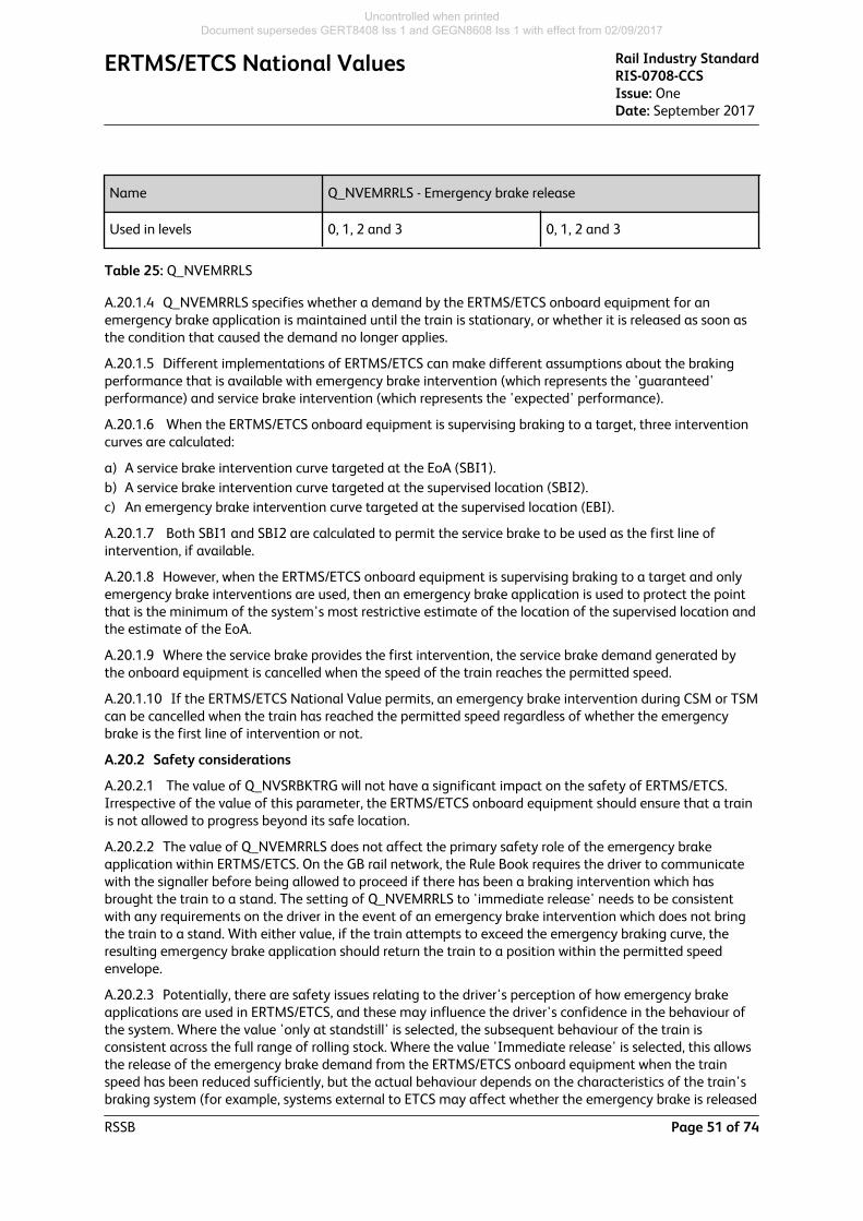
Name Q_NVEMRRLS - Emergency brake release
Used in levels 0, 1, 2 and 3 0, 1, 2 and 3
Table 25: Q_NVEMRRLS
A.20.1.4 Q_NVEMRRLS specifies whether a demand by the ERTMS/ETCS onboard equipment for anemergency brake application is maintained until the train is stationary, or whether it is released as soon asthe condition that caused the demand no longer applies.
A.20.1.5 Different implementations of ERTMS/ETCS can make different assumptions about the brakingperformance that is available with emergency brake intervention (which represents the 'guaranteed'performance) and service brake intervention (which represents the 'expected' performance).
A.20.1.6 When the ERTMS/ETCS onboard equipment is supervising braking to a target, three interventioncurves are calculated:
a) A service brake intervention curve targeted at the EoA (SBI1).b) A service brake intervention curve targeted at the supervised location (SBI2).c) An emergency brake intervention curve targeted at the supervised location (EBI).
A.20.1.7 Both SBI1 and SBI2 are calculated to permit the service brake to be used as the first line ofintervention, if available.
A.20.1.8 However, when the ERTMS/ETCS onboard equipment is supervising braking to a target and onlyemergency brake interventions are used, then an emergency brake application is used to protect the pointthat is the minimum of the system's most restrictive estimate of the location of the supervised location andthe estimate of the EoA.
A.20.1.9 Where the service brake provides the first intervention, the service brake demand generated bythe onboard equipment is cancelled when the speed of the train reaches the permitted speed.
A.20.1.10 If the ERTMS/ETCS National Value permits, an emergency brake intervention during CSM or TSMcan be cancelled when the train has reached the permitted speed regardless of whether the emergencybrake is the first line of intervention or not.
A.20.2 Safety considerations
A.20.2.1 The value of Q_NVSRBKTRG will not have a significant impact on the safety of ERTMS/ETCS.Irrespective of the value of this parameter, the ERTMS/ETCS onboard equipment should ensure that a trainis not allowed to progress beyond its safe location.
A.20.2.2 The value of Q_NVEMRRLS does not affect the primary safety role of the emergency brakeapplication within ERTMS/ETCS. On the GB rail network, the Rule Book requires the driver to communicatewith the signaller before being allowed to proceed if there has been a braking intervention which hasbrought the train to a stand. The setting of Q_NVEMRRLS to 'immediate release' needs to be consistentwith any requirements on the driver in the event of an emergency brake intervention which does not bringthe train to a stand. With either value, if the train attempts to exceed the emergency braking curve, theresulting emergency brake application should return the train to a position within the permitted speedenvelope.
A.20.2.3 Potentially, there are safety issues relating to the driver's perception of how emergency brakeapplications are used in ERTMS/ETCS, and these may influence the driver's confidence in the behaviour ofthe system. Where the value 'only at standstill' is selected, the subsequent behaviour of the train isconsistent across the full range of rolling stock. Where the value 'Immediate release' is selected, this allowsthe release of the emergency brake demand from the ERTMS/ETCS onboard equipment when the trainspeed has been reduced sufficiently, but the actual behaviour depends on the characteristics of the train'sbraking system (for example, systems external to ETCS may affect whether the emergency brake is released
ERTMS/ETCS National Values Rail Industry StandardRIS-0708-CCSIssue: OneDate: September 2017
RSSB Page 51 of 74
Uncontrolled when printed Document supersedes GERT8408 Iss 1 and GEGN8608 Iss 1 with effect from 02/09/2017

and may affect how the driver reapplies traction power). Also, forcing the train to stop has the desirableeffect of discouraging drivers from driving in ways that cause emergency interventions.
A.20.2.4 Consideration should be given to the reason why an ERTMS/ETCS emergency brake demand wasneeded in the first place. Other onboard systems, external to ERTMS/ETCS, may also command anemergency brake application; such instances are outside the scope of this document.
A.20.3 Performance considerations
A.20.3.1 The use of service brakes for TSM will add a margin between the SBI_2 and EBI, which pushes theW, P, and I curves closer to the train. The curves with Q_NVSRBKTRG / Q_NVSBTSMPERM set as 'yes' wouldapply earlier braking than if the value is set to 'no'.
A.20.3.2 Potentially, the most significant impact on performance associated with not implementing servicebrake intervention arises if it is not possible to release the emergency brake application immediately thetrain speed has dropped to the permitted speed.
A.20.3.3 From a performance perspective, the best value for the parameter Q_NVEMRRLS is 'immediate'as, in principle, trains could reach a non-zero target such as an LoA at a higher average speed if there wasno requirement to brake them to a standstill. In practice, where the target speed is zero, the differencebetween the two cases (using 'only at standstill' and using 'immediate') should be minimal. Unless theemergency brake intervention curve is based on a grossly underestimated value of the available brakingeffort, the use of the emergency brake should not allow the train to move far off the intervention curve.Where the target speed is not zero, significant performance benefits may be achieved by releasing theemergency brake prior to standstill.
A.20.4 Discussion
A.20.4.1 Q_NVSRBKTRG value has no impact on emergency braking performance. However, allowing theservice brake intervention imposes earlier braking and therefore, potentially, has an impact on performance.
A.20.4.2 Regarding Q_NVEMRRLS from a safety perspective, if Q_NVSRBKTRG is 'yes' and the servicebrake application has failed to prevent the emergency brake intervention speed being reached, it can beconsidered inappropriate to allow a train to continue to the end of its EoA/LoA without first bringing it to astop. This option has the advantage of discouraging driving practices likely to lead to dependence onemergency brake applications.
A.21 M_NVEBCL
A.21.1 Summary
A.21.1.1 The parameter described in this section relates to Gamma trains.
Name M_NVEBCL - Confidence level for emergency brake safe decelerationon dry rails
Subset-026 Minimum value 0
Subset-026 Maximum value 9
Subset-026 Default value 99.9999999%
Resolution From 0 = confidence level of 50% to 9 = confidence level of99.9999999%
ETCS Baseline Baseline 2 Baseline 3
Rail Industry StandardRIS-0708-CCSIssue: OneDate: September 2017
ERTMS/ETCS National Values
Page 52 of 74 RSSB
Uncontrolled when printed Document supersedes GERT8408 Iss 1 and GEGN8608 Iss 1 with effect from 02/09/2017

Name M_NVEBCL - Confidence level for emergency brake safe decelerationon dry rails
Used in modes N/A FS, LS, UN, SR and OS
Used in levels N/A 0, 1, 2 and 3
Table 26: M_NVEBCL
A.21.1.2 For Gamma trains, the same braking model(s) applies to trains of the same class and the sameconsist; however, the actual braking characteristics of each train will differ slightly because of differentmaintenance cycle and usage.
A.21.1.3 M_NVEBCL is used to set the minimum required probability that the train’s braking system coulddeliver the stated rate of deceleration when commanded. A corresponding derating factor (Kdry_rst) isapplied to the nominal emergency brake rate to achieve the required confidence level.
A.21.1.4 M_NVEBCL allows 10 confidence levels, ranging from 50% to 99.9999999%, to be defined. Eachconfidence level has a corresponding speed dependent Kdry_rst value which is stored onboard. The 10available steps are listed in subset-026 section 7.5.1.75.1. Based on the value of M_NVEBCL and theestimated train speed, the ERTMS/ETCS onboard will select the appropriate value of (Kdry_rst), which isused to derate the calculation of the emergency brake’s deceleration.
A.21.1.5 At different speed ranges, the probability of achieving the nominal brake rate may be different.Therefore, each speed range in the multi-step braking model may have a different de-rating factor assignedagainst it.
A.21.1.6 Using the available steps illustrated in subset-026 section 7.5.1.75.1, if an IM demands aconfidence level of 99.9%, it would set M_NVEBCL as ‘3’. When the ERTMS/ETCS onboard calculates theemergency braking curve, it will look up its Kdry_rst table and apply the corresponding Kdry_rst as aderating factor.
A.21.1.7 Kdry_rst(EBCL) is part of the equation from which the emergency braking curve is derived; othercorrection factors are also applied. Also, the rate of deceleration is applied as a prediction; it does notguarantee that the train will stop at or before the SvL. It assumes the available wheel-rail adhesion candeliver the rate of deceleration demanded by the brakes.
A.21.2 Safety considerations
A.21.2.1 Passing the SvL could lead to collision, derailment and, potentially, fatalities. Incorrect setting ofthe M_NVEBCL increases the likelihood of overrunning the SvL. Setting a higher Confidence Level mitigatesthis risk by including the probability that trains will stop before the SvL.
A.21.2.2 For a fleet of trains with the same brake model and Kdry_rst factors to meet the confidence levelset out by the IM, the reliability and availability of train braking systems has to be as consistent as possibleacross the whole fleet. The RU has the responsibility to ensure variations in the reliability and availability arereflected in the Kdry_rst factors; Kdry_rst has to be relatively low for a fleet of stock type which has lowconsistency, as Kdry_rst has to take into account the worst possible performance of that type of train. Afleet of a stock type with low Kdry_rst, servicing routes with a relatively high Confidence Level, has to have acorresponding maintenance regime to uphold its availability and reliability.
A.21.3 Performance considerations
A.21.3.1 Where an IM can set a lower Confidence Level, trains apply a lower derating factor to their rate ofemergency deceleration, reducing the predicted braking distance needed to stop before a given EoA/SvL.
A.21.3.2 An inappropriate Confidence Level could adversely impact the headway of a route and thereforeits capacity.
ERTMS/ETCS National Values Rail Industry StandardRIS-0708-CCSIssue: OneDate: September 2017
RSSB Page 53 of 74
Uncontrolled when printed Document supersedes GERT8408 Iss 1 and GEGN8608 Iss 1 with effect from 02/09/2017

A.21.3.3 An optimised setting of the Confidence Level takes safe stopping and minimised impact onperformance into account.
A.21.4 Discussion
A.21.4.1 A higher than necessary M_NVEBCL has an impact on the train service’s performance. Althoughdifferent trains have different nominal brake rates and associated Kdry_rst values, a high Confidence Levelwould inevitably require a heavier derating factor. A heavier derating factor would prevent drivers applyinga late application of brakes, which could prevent recovery from delays.
A.21.4.2 A high M_NVEBCL has an impact on headways. When setting M_NVEBCL, an IM should considerthe type of service which RUs are operating, including the frequency at which the service may encounterstopping block markers or signals.
A.21.4.3 Accurate stopping of trains depends on professional driving, and braking related information fromDMIs should only be used as guidance. The aim of the deceleration curves is to predict how a traindecelerates towards a given target. The curve takes into account several worst-case correction factors, butactual conditions may be more adverse than those used by the model. In such cases, driving while using thedeceleration curve as guidance may cause a train to exceed its EoA. Where the correction factor is over-conservative, the system may hinder the performance of train services.
A.22 M_NVAVADH
A.22.1 Summary
A.22.1.1 The parameter described in this section relates to Lambda trains.
Name M_NVAVADH - Weighting factor for available wheel-rail adhesion
Subset-026 Minimum value 0
Subset-026 Maximum value 1
Subset-026 Default value 0
Resolution 0.05
ETCS Baseline Baseline 2 Baseline 3
Used in modes N/A FS, LS, OS, SR and UN
Used in levels N/A 0, 1, 2 and 3
Table 27: M_NVAVADH
A.22.1.2 M_NVAVADH M_NVAVADH is a modifier that defines the weighting to apply to the ERTMS/ETCSonboard rolling stock correction factor Kwet_rst. In order to determine the safe emergency decelerationrate, the emergency deceleration rate is first derated by the ERTMS/ETCS onboard correction factorKdry_rst(EBCL) (see section A.21 M_NVEBCL on page 52 on M_NVEBCL). The M_NVEBCL value is set forrails in dry conditions, and, to factor in wet (low adhesion) conditions which the train may encounter, theemergency deceleration rate is further derated to provide a longer stopping distance for the train todecelerate.
A.22.1.3 The derating is achieved by applying ERTMS/ETCS onboard rolling stock correction factorKwet_rst, which is a factor of the reduced brake rate achieved by a train under the low adhesion testscenario stated in EN 15595:2009, in comparison with braking in dry conditions. For example, if the nominal
Rail Industry StandardRIS-0708-CCSIssue: OneDate: September 2017
ERTMS/ETCS National Values
Page 54 of 74 RSSB
Uncontrolled when printed Document supersedes GERT8408 Iss 1 and GEGN8608 Iss 1 with effect from 02/09/2017

brake rate (in dry conditions) of a train is 12%g, and the brake rate achieved during the low adhesion testscenario is 7%g, the Kwet_rst factor is equal to 7%g / 12%g, which is approximately 0.58. The RU isresponsible for determining and configuring the Kwet_rst values in the ERTMS/ETCS onboard equipment.Both Kdry_rst and Kwet_rst are applied under all conditions (see the process diagram in Figure 4 Schematicdiagram of how braking curves are derived on page 38).
A.22.1.4 In practice, available adhesion is usually better than that experienced under test conditions, asset out in EN 15595:2009, and an IM can adjust the impact of Kwet_rst by setting M_NVAVADH. As anexample, the braking model of a train may have a nominal brake rate of 12%g (after Kdry_rst(M_NVEBCL)is applied) and with a Kwet_rst of 0.58:
a) Setting M_NVAVADH to 0, the full magnitude of the Kwet_rst correction factor will be effective to thebrake model, that is, a rate of deceleration of (12%g x 0.58) 7%g will be applied in calculating the EBD.
b) Setting M_NVAVADH = 1, the Kwet_rst correction factor is effectively neutral, and a resultant rate ofdeceleration of 12%g will apply to calculate the EBD.
c) EN 15595:2009 sets a low adhesion reference point for rolling stock tests. For a network with a nominaladhesion performance which is better than this reference point, the IM would set M_NVAVADH to acorresponding value that reflects this improvement. For example, if the nominal adhesion was 60%better than the reference point, then the IM could set M_NVAVADH to 0.6. In our example, 10%g (60%from the low-adhesion brake rate (7%g) to the nominal brake rate (12%g)) will be applied to calculatethe EBD.
A.22.1.5 M_NVAVADH is a ‘one size fits all’ value that applies to all Gamma trains in a national value area.It is applied regardless of the actual available adhesion in an area and assumes that:
a) Kwet_rst derates the nominal brake rate to meet the test conditions set out in EN 15595:2009.b) The worst adhesion conditions on the track are no worse than the test conditions set out in EN
15595:2009.c) The factors for derating the braking distance are linear, as is the scale of available adhesion between the
test condition set out in EN 15595:2009 and dry conditions.
A.22.1.6 The lower the value of M_NVAVADH, the greater the decrease will be in the emergency brake rateused in the calculation of the EBD curve. This increases the emergency braking distance applied to the trainand advises the driver to apply the brakes earlier with a gentler deceleration. At different speed ranges, theimpact of low adhesion may be different, and a different Kwet_rst can be assigned to adjust the rate ofdeceleration to reflect the difference. However, the M_NVAVADH value is speed independent.
A.22.2 Safety considerations
A.22.2.1 Applying an incorrect M_NVAVADH may potentially cause the train to exceed its given SvL if itoverestimates the adhesion conditions. The setting of M_NVAVADH needs to reflect the nominal adhesionperformance that can be achieved in that National Area.
A.22.2.2 The M_NVAVADH has an influence on the permitted speed displayed to the driver via the DMI.The permitted speed is the maximum speed allowed but, as it does not reflect the actual wheel-railadhesion at a given location, the driver may need to drive more conservatively in low adhesion conditions.The decision of where and how much braking effort is applied is the responsibility of the train driver.
A.22.3 Performance considerations
A.22.3.1 The ERTMS/ETCS onboard deceleration model is first derated by the Kdry_rst correction factor(selected according to M_NVEBCL), then further derated by the Kwet_rst correction factor, which isweighted by M_NVAVADH. Both correction factors are fixed; they are not intended to vary upon railheadconditions. Therefore, applying the full weight of Kwet_rst (M_NVAVADH=0) to accommodate locationswith low wheel-rail adhesion will degrade performance at locations with better wheel-rail adhesion, such astunnel areas.
ERTMS/ETCS National Values Rail Industry StandardRIS-0708-CCSIssue: OneDate: September 2017
RSSB Page 55 of 74
Uncontrolled when printed Document supersedes GERT8408 Iss 1 and GEGN8608 Iss 1 with effect from 02/09/2017

A.22.3.2 Although applying a high rate of deceleration has a higher chance of slip/slide, this effect may becountered by the WSP systems effort, or other adhesion enhancing systems available, such as sanders.
A.22.4 Discussion
A.22.4.1 The number of wheelsets in a consist may also have an effect on the amount of slip-slide on wetrails. Rolling stock with a longer formation may experience less slip-slide than the same rolling stock with ashorter formation. The front wheelsets of a consist have a cleansing effect for the rear wheelsets, where thelatter would experience less railhead contaminants.
A.22.4.2 IMs and RUs can work collaboratively to manage the risk of low adhesion by the use of methodsother than M_NVAVADH, such as professional driving, sanders, sandite, or warning boards.
A.23 Q_NVKVINTSET, V_NVKVINT, M_NVKVINT
A.23.1 Summary
A.23.1.1 The three parameters described in this section relate to Lambda trains and, taken together, formspeed dependent correction factor models applicable to different types of train. These speed dependentcorrection factors apply to the calculation of the predicted braking distance, dependent on the estimatedspeed of the train and the selected type of train.
Name V_NVKVINT - Speed step used to define the integrated correctionfactor Kv_int
Subset-026 Minimum value 0 km/h
Subset-026 Maximum value 600 km/h
Subset-026 Default value N/A
Resolution 5 km/h
ETCS Baseline Baseline 2 Baseline 3
Used in modes N/A FS, LS, OS, SR and UN
Used in levels N/A 0, 1, 2 and 3
Table 28: V_NVKVINT
A.23.1.2 V_NVKVINT defines the speed at which a new M_NVKVINT value applies. Each V_NVKVINT doesnot have to be incremented by the same amount, nor do they have to correspond to the speed steps used inthe conversion model. Figure 12 Four steps Kv_int models on page 58 shows an example of a set/sub-setof Kv_int with V_NVKVINT values corresponding to, for example, V1 and V2 in Figure11 An example of afour steps Kv_int on page 58. A maximum of five speed steps can be defined.
Name Q_NVKVINTSET - Type of Kv_int set
Subset value 00 - Freight trains
Rail Industry StandardRIS-0708-CCSIssue: OneDate: September 2017
ERTMS/ETCS National Values
Page 56 of 74 RSSB
Uncontrolled when printed Document supersedes GERT8408 Iss 1 and GEGN8608 Iss 1 with effect from 02/09/2017

Name Q_NVKVINTSET - Type of Kv_int set
01 - Conventional passenger trains
Subset-026 Default value N/A
Resolution Either 00 or 01; 10-11 are spares
ETCS Baseline Baseline 2 Baseline 3
Used in modes N/A FS, LS, OS, SR and UN
Used in levels N/A 0, 1, 2 and 3
Table 29: Q_NVKVINTSET
A.23.1.3 Q_NVKVINTSET describes the type of train (passenger or freight) to which the associated set ofM_NVKVINT and V_NVKVINT applies. 'Freight trains' are those with the brake position in Freight in P orFreight in G. 'Conventional passenger trains' are those with the brake position in Passenger in P. For trainsdescribed as conventional passenger trains, the set of speed dependent correction factors (M_NVKVINT,V_NVKVINT, A_NVP12 and A_NVP23) which follow it are applicable. Figure 12 Four steps Kv_int models onpage 58 shows the structure of the speed dependent sets for freight and convention passenger trains.
Name M_NVKVINT - Integrated correction factor Kv_int
Subset-026 Minimum value 0
Subset-026 Maximum value 2.54
Subset-026 Default value 0.7
The List of National / Default Data in A.3.2 of the SRS-026 states: Thedefault value of the correction factor Kv_int shall be valid for anybrake position, speed and maximum emergency brake deceleration.This means that the Kv_int model is valid for all train types and doesneither contain any speed step nor any pivot deceleration limit.
Resolution 0.02
ETCS Baseline Baseline 2 Baseline 3
Used in modes N/A FS, LS, OS, SR and UN
Used in levels N/A 0, 1, 2 and 3
Table 30: M_NVKVINT
A.23.1.4 M_NVKVINT defines the speed dependent integrated correction factor that is applied to theemergency brake rate derived from the conversion model for each speed range defined by V_NVKVINT. Thecombination of the different speed ranges defined by V_NVKVINT, and the correction factor applicable to
ERTMS/ETCS National Values Rail Industry StandardRIS-0708-CCSIssue: OneDate: September 2017
RSSB Page 57 of 74
Uncontrolled when printed Document supersedes GERT8408 Iss 1 and GEGN8608 Iss 1 with effect from 02/09/2017

that speed range as defined by M_NVKVINT, provide a set of Kv_int correction factors, as shown in Figure 12 Four steps Kv_int models on page 58.
A.23.1.5 The IM is able to use the integrated correction factors to adjust the braking distance to suit theinfrastructure layout or available adhesion. The correction factor is used to adjust the brake rate determinedby the conversion model to tune the ETCS braking curve to more accurately align with the characteristics ofa legacy signalling system; for example, performance, driving style or to reflect the available wheel-railadhesion.
A.23.1.6 Two sets of speed dependent correction factors (Kv_int) can be defined, as shown in Figure 12 Four steps Kv_int models on page 58: one set for freight trains, and one set for conventional passengertrains. The two sets are distinguished from one another using parameter Q_NVKINTSET. The conventionalpassenger trains set comprises two sub-sets, the application of which is dependent on the maximumemergency braking deceleration of the train (calculated by the conversion model) in relation to lower andupper deceleration limits A_NVP12 and A_NVP23 (see A.24 A_NVP12, A_NVP23 on page 59).
Figure 11: An example of a four steps Kv_int
Figure 12: Four steps Kv_int models
A.23.1.7 For freight trains, the M_NVKVINT value used is dependent on the train's current speed relativeto the speed ranges defined by V_NVKVINT. For conventional passenger trains, the selection ofM_NVKVINT has to take ERTMS/ETCS National Values A_NVP12 and A_NVP23 into consideration. For bothbrake settings, the selected M_NVKVINT value is multiplied with the relevant rate of deceleration from thebraking model calculated by the conversion model.
A.23.2 Safety considerations
A.23.2.1 The correction factors used for the Lambda braking model are different to the ones used for theGamma braking model in that the IM can decrease the nominal braking distance by setting theM_NVKVINT to be larger than one. The safety implication is that a train might not be able to stop before itsSvL. However, the conversion model is comparatively conservative for current rolling stock on the GBmainline railway, which could mitigate this hazard.
Rail Industry StandardRIS-0708-CCSIssue: OneDate: September 2017
ERTMS/ETCS National Values
Page 58 of 74 RSSB
Uncontrolled when printed Document supersedes GERT8408 Iss 1 and GEGN8608 Iss 1 with effect from 02/09/2017

A.23.3 Performance considerations
A.23.3.1 Setting M_NVKVINT to be too low can increase the predicted braking distance to be much longerthan that which the train could achieve.
A.23.3.2 Setting M_NVKVINT to zero, or near zero, will create a braking distance of infinity and the trainwill be unable to move.
A.23.3.3 Unlike braking related ERTMS/ETCS National Values for Gamma trains, M_NVKVINT can be set tobe higher than the value of one, making the applicable rate of deceleration to be higher than thatgenerated by the conversion model.
A.23.4 Discussion
A.23.4.1 KVINT, in combination with KRINT (A.25 L_NVKRINT, M_NVKRINT on page 63) and KTINT(A.26 M_NVKTINT on page 66), is used to correlate the generated brake model with the predicted brakingperformance of trains. Therefore, in the setting of KVINT, the IM may have to take the conversion modelinto account, and analyse if the conversion model correctly reflects the general braking behaviour of trains.
A.23.4.2 KVINT could be used to increase the probability of trains stopping before the EoA/SvL. An IMcould use KVINT to reduce the possibility of exceeding an EoA/SvL by requiring drivers to brake earlier andmore gently towards an EoA/SvL.
A.23.4.3 KVINT could be used to reflect the available wheel-rail adhesion in general. An IM could set asmaller KVINT for a National Area for periods when wheel-rail adhesion is predicted to be low.
A.23.4.4 An IM may wish to influence the EBD for different ranges of speed, for example, setting a lowKv_int can be used at low speeds to increase the confidence of not exceeding SvLs. At the same time, avalue of one or greater can be applied to high-speed ranges, to take account of transitions from higher tolower speed limits without over-extending the predicted braking distances.
A.24 A_NVP12, A_NVP23
A.24.1 Summary
A.24.1.1 The two parameters described in this section relates to Lambda trains.
Name A_NVP12 - Lower deceleration limit to determine the set of Kv_int tobe used
Subset-026 Minimum value 0 m/s2
Subset-026 Maximum value 3.15 m/s2
Subset-026 Default value N/A
Resolution 0.05 m/s2
ETCS Baseline Baseline 2 Baseline 3
Used in modes N/A FS, LS, OS, SR and UN
Used in levels N/A 0, 1, 2 and 3
Table 31: A_NVP12
ERTMS/ETCS National Values Rail Industry StandardRIS-0708-CCSIssue: OneDate: September 2017
RSSB Page 59 of 74
Uncontrolled when printed Document supersedes GERT8408 Iss 1 and GEGN8608 Iss 1 with effect from 02/09/2017

Name A_NVP23 - Upper deceleration limit to determine the set of Kv_int tobe used
Subset-026 Minimum value 0 m/s2
Subset-026 Maximum value 3.15 m/s2
Subset-026 Default value N/A
Resolution 0.05 m/s2
ETCS Baseline Baseline 2 Baseline 3
Used in modes N/A FS, LS, OS, SR and UN
Used in levels N/A 0, 1, 2 and 3
Table 32: A_NVP23
Rail Industry StandardRIS-0708-CCSIssue: OneDate: September 2017
ERTMS/ETCS National Values
Page 60 of 74 RSSB
Uncontrolled when printed Document supersedes GERT8408 Iss 1 and GEGN8608 Iss 1 with effect from 02/09/2017

Figure 13: Process of extracting Kv_int
A.24.1.2 For conventional passenger trains (not applicable to freight in P or G), two sets of speeddependent correction factors are defined: Kv_int_x_a and Kv_int_x_b. A_NVP12 represents the maximumthreshold up to where Kv_int_x_a is applied and A_NVP23 represents the minimum threshold from whereKv_int_x_b is applied. The ERTMS/ETCS onboard uses the maximum rate of deceleration generated fromthe train's conversion brake model (A_ebmax), to compare against A_NVP12 and A_NVP23 to determinewhich set of speed dependent correction factors are applicable (see subset-026 3.13.6.2.1.8). If the valuesof A_NVP12 and A_NVP23 are different, the speed dependent correction factors applicable to trains withemergency brake deceleration falling between the two values are interpolated linearly by the followingequation:
A.24.1.3 The chart at the top of Figure 13 Process of extracting Kv_int on page 61 shows how the two setsof Kv_int correction factors are linearly connected.
ERTMS/ETCS National Values Rail Industry StandardRIS-0708-CCSIssue: OneDate: September 2017
RSSB Page 61 of 74
Uncontrolled when printed Document supersedes GERT8408 Iss 1 and GEGN8608 Iss 1 with effect from 02/09/2017

A.24.2 Safety considerations
A.24.2.1 The safety considerations for this ERTMS/ETCS National Value depend upon the setting of Kv_int.Where Kv_int_x_a has a greater value than Kv_int_x_b, setting A_NVP12 to a high value would result inmore trains using the Kv_int_x_a set, increasing the probability that better-braked trains might exceed theirEoA/SvL due to sliding in low adhesion conditions. This can have safety implications if an inappropriatecorrection value is used that derives a deceleration that exceeds the actual capability of the train.Conversely, the use of a more conservative Kv_int_x_b for trains that have a higher maximum rate ofdeceleration may reduce the likelihood of slip/slide by indicating an earlier and lighter application of brakeson the approach to the EoA, which allows longer distance to recover if the train does slip/slide.
A.24.2.2 Setting A_NVP12 and A_NVP23 very close together, with Kv_int_x_a and Kv_int_x_b havingnoticeable differences, may cause drivability issues. Two similar train consists with similar characteristicsmay have different sets of Kv_int correction factors imposed upon them. If the difference of their A_ebmaxputs one train into the Kv_int_x_a section, while the other train is in the Kv_int_x_b section, the two trainsmay have very different EBD imposed upon them, while having very subtle differences in drivingcharacteristic. A driver may not realise the need to adjust driving practice until the emergency brake isdeployed by the ERTMS/ETCS onboard.
A.24.3 Performance considerations
A.24.3.1 Where Kv_int_x_a has a greater value than Kv_int_x_b, setting A_NVP23 to a low value wouldresult in more trains using the Kv_int_x_b set, which may unnecessarily derate their braking capability,thereby extending the length of the braking curves and impacting on performance.
A.24.4 Discussion
A.24.4.1 The setting of an effective A_NVP12/23 depends on the two sets of Kv_int models forconventional passenger trains, and the ETCS onboard derived A_ebmax.
A.24.4.2 If an IM decides to use one set only of Kv_int for conventional passenger trains, A_NVP12/23does not need to be set to any values, that is, the use of ERTMS/ETCS Default Values does not call forA_NVP12/23.
A.24.4.3 If the A_ebmax is at the mid-range of the A_NVP12/23 scales, setting A_NVP12 to be on the highend would force more Lambda conventional passenger trains to use the Kv_int_x_a set; and Kv_int_x_b setif A_NVP23 is at the low end. Theoretically, dividing the A_NVP12/23 range into three equal portionsmakes an evenly distributed use of both Kv_int sets for conventional passenger trains.
A.24.4.4 The absolute differences in the values between Kv_int_x_a and Kv_int_x_b could affect howA_NVP12/23 should be set. Table 33 Comparison of how A_NVP12, A_NVP23, Kv_int_x_a and Kv_int_x_baffects the outcome (all values are in relative terms) on page 62 sets out a qualitative comparison of fourdifferent scenarios.
Large differences between
Kv_int_x_a and Kv_int_x_b
Little differences between
Kv_int_x_a and Kv_int_x_b
A_NVP12 and A_NVP23 being farapart
Large difference in KVINTs andA_NVP12 and A_NVP23 being farapart provides gradualdifferences as A_ebmax variesalong the scale.
Trains with little differences inA_ebmax would cause a small butnoticeable difference in the EBDcurve.
Little differences in correctionfactors Kv_int between A_NVP12and A_NVP23, and almostidentical Kv_int for the entirerange.
EBDs would have similar rate forall trains at similar speed, makingtimetable performance predictioneasier.
Rail Industry StandardRIS-0708-CCSIssue: OneDate: September 2017
ERTMS/ETCS National Values
Page 62 of 74 RSSB
Uncontrolled when printed Document supersedes GERT8408 Iss 1 and GEGN8608 Iss 1 with effect from 02/09/2017

Large differences between
Kv_int_x_a and Kv_int_x_b
Little differences between
Kv_int_x_a and Kv_int_x_b
A_NVP12 and A_NVP23 beingclose together
Large step differences in EBDcurves between trains which mayhave similar A_ebmax.
It would cause drivingcharacteristic for trains withslightly different A_ebmax to bevery different.
Very little difference across therange.
It might be simpler if both sets ofKv_int are unified, with A_NVP12to be the same as A_NVP23.
Table 33: Comparison of how A_NVP12, A_NVP23, Kv_int_x_a and Kv_int_x_b affects the outcome (allvalues are in relative terms)
A.25 L_NVKRINT, M_NVKRINT
A.25.1 Summary
A.25.1.1 The two parameters described in this section relate to Lambda trains.
Name L_NVKRINT - Train length step used to define the integratedcorrection factor Kr_int
Subset-026 Minimum value 0 m
Subset-026 Maximum value 2700 m
Subset-026 Default value N/A
Resolution 0 0 m
1 25 m
2 50 m
ERTMS/ETCS National Values Rail Industry StandardRIS-0708-CCSIssue: OneDate: September 2017
RSSB Page 63 of 74
Uncontrolled when printed Document supersedes GERT8408 Iss 1 and GEGN8608 Iss 1 with effect from 02/09/2017

Name L_NVKRINT - Train length step used to define the integratedcorrection factor Kr_int
3 75 m
4 100 m
5 150 m
6 200m
7 300 m
8-30 (steps of 100 m)
31 2700 m
ETCS Baseline Baseline 2 Baseline 3
Used in modes N/A FS, LS, OS, SR and UN
Used in levels N/A 0, 1, 2 and 3
Table 34: L_NVKRINT
Name M_NVKRINT - Integrated correction factor Kr_int
Subset-026 Minimum value 0
Subset-026 Maximum value 1.55
Subset-026 Default value 0.9
The List of National / Default Data in A.3.2 of the SRS-026 states: Thedefault value of the correction factor Kr_int shall be valid for any trainlength. This means that the Kr_int model does not contain any trainlength step.
Resolution 0.05
ETCS Baseline Baseline 2 Baseline 3
Used in modes N/A FS, LS, OS, SR and UN
Used in levels N/A 0, 1, 2 and 3
Table 35: M_NVKRINT
A.25.1.2 Kr_int is a set of train length dependent integrated correction factors that apply to Lambda trainsonly.
A.25.1.3 Wheelsets towards the front of a train consist, in particular on long trains, may experience adifferent wheel-rail coefficient of friction to wheelsets towards the rear. This is because preceding wheelsets
Rail Industry StandardRIS-0708-CCSIssue: OneDate: September 2017
ERTMS/ETCS National Values
Page 64 of 74 RSSB
Uncontrolled when printed Document supersedes GERT8408 Iss 1 and GEGN8608 Iss 1 with effect from 02/09/2017

may displace water and contaminants on the railhead, which decreases the amount of contaminantsexperienced by the following wheelsets. When a train experiences low wheel-rail adhesion conditions, alonger train consist that is made up of the same stock type as a shorter consist could have a shorter brakingdistance than the shorter consist.
A.25.1.4 In addition, low adhesion areas may exist in short lengths, and may therefore have a worse effecton shorter trains than long trains. When a short train applies its brakes, a larger portion of its wheels arebraking on tracks with patches of extra low adhesion than when a longer train brakes at the same stretch oftrack.
A.25.1.5 Kr_int provides the means for the IM to influence the calculation of the EBD curve to take accountof the impact of the train length on the braking capability of the train.
A.25.1.6 It is possible to define five individual factors within a Kr_int set in the form of a step function,starting from L_NVKRINT=0. The ERTMS/ETCS onboard will select and apply the correspondingM_NVKRINT value applicable to the train length range for the train length acquired as part of train data. Aset of Kr_int with five values is shown in Figure 14 An example of a set of M_KRINT correction factors withfive steps on page 65.
Figure 14: An example of a set of M_KRINT correction factors with five steps
A.25.1.7 In Figure 14 An example of a set of M_KRINT correction factors with five steps on page 65, thevertical axis could be associated with the 'contaminant clearing performance' and 'permitted traffic' forthe horizontal axis.
A.25.2 Safety considerations
A.25.2.1 If the IM sets a Kr_int value that is too high it may lead to an over-estimation of the train brakingcapability in relation to the train length, which could lead to an overspeed, or passing of an SvL. If the driverenters an incorrect train length, this could have the same effect.
ERTMS/ETCS National Values Rail Industry StandardRIS-0708-CCSIssue: OneDate: September 2017
RSSB Page 65 of 74
Uncontrolled when printed Document supersedes GERT8408 Iss 1 and GEGN8608 Iss 1 with effect from 02/09/2017

A.25.3 Performance considerations
A.25.3.1 Setting a Kr_int value too low would derate the EBD to have a gentler deceleration curve,requiring the driver to start braking earlier for a speed restriction or an EoA/SvL with a consequential impacton performance.
A.25.4 Discussion
A.25.4.1 One of the assumptions which Kr_int is based on is that longer trains have more wheelsets, whichis not necessarily the case. It is therefore important to consider the number of wheelsets in setting theKr_int values.
A.25.4.2 The value of Kr_int is influenced by:
a) The line environment; for example covered lines may experience very little railhead contamination.b) The type of contamination on the rail head and the rate at which train wheels can displace the
contamination for the remaining wheels to brake on 'clean tracks'.c) The length of low adhesion areas in comparison with the length of trains that normally travel over them.
A.25.4.3 When setting KRINT, the values have to be considered alongside other contributing correctionfactors in the EBD equation, namely, Kv_int correction factors.
A.26 M_NVKTINT
A.26.1 Summary
A.26.1.1 The parameter described in this section relates to Lambda trains.
Name M_NVKTINT - Integrated correction factor Kt_int
Subset-026 Minimum value 0
Subset-026 Maximum value 1.55
Subset-026 Default value 1.1
Resolution 0.05
ETCS Baseline Baseline 2 Baseline 3
Used in modes N/A FS, LS, OS, SR and UN
Used in levels N/A 0, 1, 2 and 3
Table 36: M_NVKTINT
A.26.1.2 Kt_int is an integrated correction factor that is applied on Lambda trains to influence the safeemergency brake build-up time, and hence the offset between the EBI curve and the EBD curve. The EBIcurve is the final instance at which the emergency brake has to be commanded for the train to stay withinthe EBD curve.
A.26.1.3 Kt_int is different from the correction factors, Kv_int and Kr_int, in that it is a single parameterapplicable to all train lengths and speeds.
A.26.1.4 When the emergency brake is commanded, a train with standard air brakes would have valves onthe brake pipe opened to vent the pressurised air to the atmosphere. The brake pipe's air pressure dropsuntil it equalises with atmospheric pressure, or until the valves are shut. The time delay between brake
Rail Industry StandardRIS-0708-CCSIssue: OneDate: September 2017
ERTMS/ETCS National Values
Page 66 of 74 RSSB
Uncontrolled when printed Document supersedes GERT8408 Iss 1 and GEGN8608 Iss 1 with effect from 02/09/2017

command and brake application is defined as T_brake_emergency. T_brake_emergency is derived from astandardised calculation for all Lambda trains, which cannot fully account for differences in train brakingsystems due to variations in design and maintenance regimes. Kt_int provides a means to adjust thecalculated T_brake_emergency value to correct for these differences through the derivation of parameterT_be using the equation: T_be = Kt_int * T_brake_emergency.
A.26.1.5 T_be is subsequently applied to calculate the offset between the EBI curve and the EBD curve. Thegreater the value of Kt_int, the greater the offset, and the earlier the emergency brake may be commanded.
A.26.2 Safety considerations
A.26.2.1 Applying a Kt_int which is too low, could result in T_be being shorter than the actual brakeapplication time achievable by a train. This would result in the emergency brake being commanded too latefor the train to decelerate within the EBD curve, which could cause the SvL to be exceeded.
A.26.3 Performance considerations
A.26.3.1 Setting a Kt_int value too high would increase the offset between the EBD and EBI, andsubsequently all curves related to braking will be displayed to the driver earlier than necessary, with aconsequential impact on performance.
A.26.4 Discussion
A.26.4.1 T_brake_emergency is calculated for all Lambda trains according to a standardised formula thatconsiders the following train length ranges:
a) Train length of less than 900 m.b) Train length of greater than 900 m but shorter than 1500 m.
A.26.4.2 If Kt_int is set to accommodate a small proportion of Lambda trains which perform worse thanthe T_brake_emergency, a longer braking distance would apply to all trains, including those with quickerresponding emergency braking systems.
A.26.4.3 The setting of Kt_int is a trade-off between safety and performance dependent on the range ofperformance of the braking systems of Lambda trains which operate on the infrastructure.
ERTMS/ETCS National Values Rail Industry StandardRIS-0708-CCSIssue: OneDate: September 2017
RSSB Page 67 of 74
Uncontrolled when printed Document supersedes GERT8408 Iss 1 and GEGN8608 Iss 1 with effect from 02/09/2017

Definitions
A_NVMAXREDADH1, A_NVMAXREDADH2,A_NVMAXREDADH3
Maximum deceleration, assumed by the ETCSbraking model, under reduced adhesion conditions(1) (2) (3).
A_NVP12 Lower deceleration limit used by the ETCS brakingmodel to determine the set of Kv to be used.
A_NVP23 Upper deceleration limit used by the ETCS brakingmodel to determine the set of Kv to be used.
Baseline A set of specifications that forms a recognised legalversion of ERTMS/ETCS.
Brake position Brake position (Passenger or Goods) corresponds tothe brake cylinder application and release timingsselected on the automatic air-brake distributors, seeGMRT2045 Issue 4 Appendix J for further details.
Class B systems Existing non-ETCS national signalling systems, forlist of Class B systems, see European Union Agencyfor Railways technical documents 'List of CCS ClassB systems, ERA/TD/2011-11, version 3.0'.
Ceiling Speed Monitoring (CSM) ETCS Ceiling Speed Monitoring.
D_NVOVTRP An ETCS variable that is used for setting theMaximum distance for overriding an ETCS train trip.
D_NVPOTRP An ETCS variable that is used for setting theMaximum distance for reversing in ETCS Post Tripmode.
D_NVROLL An ETCS variable that is used for setting the Rollaway distance limit.
D_NVSTFF An ETCS variable that is used for setting theMaximum distance for running in ETCS StaffResponsible mode.
Emergency Brake Deceleration (EBD) The location (or deceleration curve) calculated bythe ERTMS/ETCS onboard, if the train is to beslowed down by use of emergency brakes, usingcurrent or estimated speed, and other trainparameters.
Emergency Brake Intervention (EBI) The location which the emergency brakes have toapply if the train is not to exceed the EBD position(or deceleration curve).
End of Authority (EoA) An End of Authority is a location to which the trainis permitted to proceed and where target speed =zero.
Full Supervision mode (FS) ERTMS/ETCS on-board equipment mode giving fullprotection against overspeed and overrun.
Rail Industry StandardRIS-0708-CCSIssue: OneDate: September 2017
ERTMS/ETCS National Values
Page 68 of 74 RSSB
Uncontrolled when printed Document supersedes GERT8408 Iss 1 and GEGN8608 Iss 1 with effect from 02/09/2017

Isolation mode (IS) ETCS Isolation Mode. When the ERTMS/ETCS on-board equipment is disconnected from the vehiclebraking system. Isolation is indicated to the driver.
Infrastructure Manager (IM) Any ‘body’ or undertaking that is responsible inparticular for establishing and maintaining railwayinfrastructure, or part thereof, as defined in article 3of Directive 91/440/EEC, which may also include themanagement of infrastructure control and safetysystems. The functions of the infrastructuremanager on a network or part of a network may beallocated to different bodies or undertakings . Article3 (b) of Directive 2004/49/EC.
L_NVKRINT An ETCS variable that is used for setting the trainlength step used to define the integrated correctionfactor Kr.
Limit of Authority (LoA) A Limit of Authority is the place beyond which thetrain has no information but to which the train isauthorised to run with a defined target speed higherthan zero. The train is expected to receive newinformation before passing the Limit of Authority.
Limited Supervision mode (LS) ERTMS/ETCS on-board equipment mode givingpartial protection against over speed and over run.The driver has to observe and obey to line sidesignals and operating rules when in limitedsupervision mode.
M_NVAVADH An ETCS variable that is used for setting theweighting factor for available wheel/rail adhesionused by the ETCS braking model.
M_NVCONTACT An ETCS variable that is used for setting the ERTMS/ETCS onboard reaction when T_NVCONTACTexpires.
M_NVDERUN An ETCS variable that is used for setting the entry ofETCS Driver ID permitted while running.
M_NVEBCL An ETCS variable that is used for setting theconfidence level ETCS braking model for emergencybrake safe deceleration on dry rails.
M_NVKRINT An ETCS variable that is used for setting the ETCSbraking model's integrated correction factor Kr.
M_NVKTINT An ETCS variable that is used for setting the ETCSbraking model's integrated correction factor Kt.
M_NVKVINT An ETCS variable that is used for setting the ETCSbraking model's integrated correction factor Kv.
Non Leading mode (NL) ERTMS/ETCS on-board equipment mode when it isconnected to an active cab which is not in theleading engine of the train.
ERTMS/ETCS National Values Rail Industry StandardRIS-0708-CCSIssue: OneDate: September 2017
RSSB Page 69 of 74
Uncontrolled when printed Document supersedes GERT8408 Iss 1 and GEGN8608 Iss 1 with effect from 02/09/2017

No Power mode (NP) ERTMS/ETCS on-board equipment mode in whichthe on-board equipment is not powered and theemergency brake is commanded.
On Sight mode (OS) ERTMS/ETCS on-board equipment mode that givesthe driver partial responsibility for the safe controlof his train. In this mode the train possesses amovement authority but the track ahead might beoccupied by another train.
Passive Shunting mode (PS) ERTMS/ETCS on-board equipment mode that allowsthe on-board of a slave engine to be part of ashunting consist; or to carry on a shuntingmovement with a single engine fitted with one on-board equipment and two cabs, when the driver hasto change the driving cab.
Post Trip mode (PT) ERTMS/ETCS on-board equipment mode that isentered after a train trip when the train has beenbrought to a stand and the driver has acknowledgedthe situation.
Q_NVDRIVER_ADHES An ETCS variable that is used for setting thequalifier for the modification of ETCS tracksideadhesion factor by the driver.
Q_NVEMRRLS An ETCS variable that is used for setting thequalifier for ETCS Emergency Brake Release.
Q_NVGUIPERM An ETCS variable that is used to define whether theuse guidance curve is permitted in the brakingmodel.
Q_NVINHSMICPERM An ETCS variable that is used for setting thepermission to inhibit ETCS compensation of thespeed measurement inaccuracy.
Q_NVKINT An ETCS variable that is used for setting thequalifier for the ETCS braking model integratedcorrection factors.
Q_NVKVINTSET An ETCS variable that is used to describe the type ofKv_int set which it is intending to set.
Q_NVLOCACC An ETCS variable that is used for setting the defaultlocation accuracy of a balise location.
Q_NVSBFBPERM An ETCS variable that is used to define whether theuse of service brake feedback is permitted in theETCS braking model.
Q_NVSBTSMPERM An ETCS variable that is used to define whether theuse of service brake is permitted in target speedmonitoring.
Q_NVSRBKTRG An ETCS variable that is used for setting thepermission to use service brake when braking to atarget is supervised.
Rail Industry StandardRIS-0708-CCSIssue: OneDate: September 2017
ERTMS/ETCS National Values
Page 70 of 74 RSSB
Uncontrolled when printed Document supersedes GERT8408 Iss 1 and GEGN8608 Iss 1 with effect from 02/09/2017

Radio Electronic Token Block (RETB) RETB is a method of protecting a single line ofrailway through the use of an electronic interlockingand a radio link to the trains which use the line.
Radio Infill Unit (RIU) A trackside component that transmits infillinformation by radio to trains.
Railway Undertaking (RU) Any private or public undertaking the principalbusiness of which is to provide rail transport servicesfor goods and/or passengers, with a requirementthat the undertaking must ensure traction; this alsoincludes undertakings which provide traction only.Article 3 (a) of Directive 2004/49/EC.
Roll In Roll Out The time it takes for train to decelerate from linespeed to a stopping station, dwell, then accelerateto line speed again, where a higher rate ofdeceleration and acceleration will gain higherperformance.
Reversing mode (RV) ERTMS/ETCS on-board equipment mode that allowsthe driver to change the direction of movement ofthe train whilst controlling the train from the samecab.
Safe emergency deceleration rate The safe emergency deceleration rate is the valueapplied to generate the EBD curve. The value isderived from applying derating factors and route'sgradient to the emergency deceleration rate, whichis an extract from the train's braking model or aderivative from the conversion model.
Service brake deceleration(SBD) The location (or deceleration curve) calculated bythe ERTMS/ETCS onboard, if the train is to beslowed down by use of service brakes, using currentor estimated speed, and other train parameters.
Stand By mode (SB) ERTMS/ETCS on-board equipment mode that is adefault mode when the on-board equipment ispowered up or that is entered when shunting or non-leading mode is left or when the active cab is closed.
Service brake intervention (SBI) ETCS Service Brake Intervention. The location whichthe service brakes have to apply if the train is not toexceed the SBD position (or deceleration curve).
System Failure mode (SFM) ERTMS/ETCS on-board equipment mode enteredwhen a fatal failure which could affect safety isfound.
Shunting mode (SH) ERTMS/ETCS on-board equipment operating modewhich allows the train to move in shunting, withoutavailable train data.
Sleeping mode (SL) ERTMS/ETCS on-board equipment mode that isused for the on-board equipment in slave enginescontrolled by a leading engine.
ERTMS/ETCS National Values Rail Industry StandardRIS-0708-CCSIssue: OneDate: September 2017
RSSB Page 71 of 74
Uncontrolled when printed Document supersedes GERT8408 Iss 1 and GEGN8608 Iss 1 with effect from 02/09/2017

System National mode (SN) ERTMS/ETCS on-board equipment mode in whichthe supervision of the train is ensured by a NationalSystem.
Staff Responsible mode (SR) ETCS Staff Responsible mode.
Supervised location (SvL) Supervised Location, which could be defined on-board as the end of the overlap, the Danger Point, orthe End of Authority.
T_NVCONTACT An ETCS variable that is used for setting themaximum time without new ETCS 'safe' message.
T_NVOVTRP An ETCS variable that is used for setting themaximum time for overriding the ETCS train trip.
Trip mode (TR) ERTMS/ETCS on-board equipment mode (e.g.entered when passing an EOA), resulting in anapplication of the emergency brake that can only berevoked at standstill and with additionalprecautions.
TSM ETCS Target Speed Monitoring.
Unfitted mode (UN) ERTMS/ETCS on-board equipment mode allowing afitted train to run in an unfitted area.
V_NVALLOWOVTRP An ETCS variable that is used for setting themaximum speed limit allowing the driver to selectthe ETCS 'override EoA' function.
V_NVKVINT An ETCS variable that is used for setting the speedstep used to define the ETCS integrated correctionfactor Kv.
V_NVLIMSUPERV An ETCS variable that is used for setting thepermitted speed while operating in ETCS LimitedSupervision mode.
V_NVONSIGHT An ETCS variable that is used for setting thepermitted speed while operating in ETCS On Sightmode.
V_NVREL An ETCS variable that is used for setting thepermitted speed while operating in ETCS ReleaseSpeed mode.
V_NVSHUNT An ETCS variable that is used for setting thepermitted speed while operating in ETCS Shuntingmode.
V_NVSTFF An ETCS variable that is used for setting thepermitted speed while operating in ETCS StaffResponsible mode.
V_NVSUPOVTRP An ETCS variable that is used for setting thepermitted speed limit to be supervised to, when theETCS 'override EoA' function is active.
Rail Industry StandardRIS-0708-CCSIssue: OneDate: September 2017
ERTMS/ETCS National Values
Page 72 of 74 RSSB
Uncontrolled when printed Document supersedes GERT8408 Iss 1 and GEGN8608 Iss 1 with effect from 02/09/2017

V_NVUNFIT An ETCS variable that is used for setting thepermitted speed while operating in ETCS Unfittedmode.
ERTMS/ETCS National Values Rail Industry StandardRIS-0708-CCSIssue: OneDate: September 2017
RSSB Page 73 of 74
Uncontrolled when printed Document supersedes GERT8408 Iss 1 and GEGN8608 Iss 1 with effect from 02/09/2017

References
The Catalogue of Railway Group Standards gives the current issue number and status of documentspublished by RSSB. This information is also available from http://www.rssb.co.uk/railway-group-standards.
RGSC 01 Railway Group Standards Code
RGSC 02 Standards Manual
Documents referenced in the text
(EU) 2016/919 Control Command and Signalling, TechnicalSpecifications for Interoperability
NS-ERTMS-SAF-4022 ERTMS National Values – D_NVROLL
RSSB-ERTMS-OC ERTMS Operational Concept
T093 Development of national values for ERTMS traincontrol parameters – Final Report, RSSB, version1.0.5, 31 March 2004
Subset-026 ERTMS/ETCS Class 1 System RequirementsSpecification, v3.6.0, ERA, 13 May 2016
ERA/TD/2011-11, version 3.0 List of CCS Class B systems
BS EN 15595:2009 Railway applications. Braking. Wheel slideprotection
Rail Industry StandardRIS-0708-CCSIssue: OneDate: September 2017
ERTMS/ETCS National Values
Page 74 of 74 RSSB
Uncontrolled when printed Document supersedes GERT8408 Iss 1 and GEGN8608 Iss 1 with effect from 02/09/2017