ertms on satellite galileo game changer
TRANSCRIPT

Project: ERSAT GGC
1 ERSAT GCC_WP2_D2.1_Enhanced Functional ERTMS Architecture
Capable of using GNSS and Public Radio TLC Technologies_01
ERTMS on SATELLITE Galileo Game Changer
Enhanced Functional ERTMS Architecture Capable of using
GNSS and Public Radio TLC Technologies
Due date of deliverable: 31/05/2018
Actual submission date: 19/06/2018
Leader/Responsible of this Deliverable: ASTS
Reviewed: Y
Document status
Revision Date Description
0 05/06/2018 First Revision
1 19/06/2018 Document review and integration with WP2 partners’
contributions
Project funded from the European Union’s Horizon 2020 research and innovation
programme
Dissemination Level
PU Public X
CO Confidential, restricted under conditions set out in Model Grant Agreement
CI Classified, information as referred to in Commission Decision 2001/844/EC
Start date of project: 01/12/2017 Duration: 24 months

Project: ERSAT GGC
2 ERSAT GCC_WP2_D2.1_Enhanced Functional ERTMS Architecture
Capable of using GNSS and Public Radio TLC Technologies_01
REPORT CONTRIBUTORS
Name Company Details of Contribution
Giuseppe Casalinuovo Fabio Pognante Alfio Beccaria
ASTS Authors
Daniele Caronti
Andrea Olmi
Marco Scarozza
Gaetano Ceneri
Salvatore Buonincontri
RFI Review of the whole document
Stefano Benusiglio
Veronica Tripodoro BVI Review of the whole document
Claudio Evangelisti ITCF Review of the whole document
Bernd Gonska DLR Review of the whole document
José Bueno
Susana Herranz
Daniel Molina
Miguel Fernandez
Miguel Lopez
Rodrigo Caceres
CEDEX Review of the whole document
Beatriz Sierra Barba INECO Review of the whole document
DOCUMENT APPROVAL
Document Code Rev. Approved Authorized Date
ERSAT GCC_WP2_D2.1_Enhanced Functional
ERTMS Architecture Capable of using GNSS
and Public Radio TLC Technologies_01
01 TMT Massimiliano
Ciaffi 2018/06/19

Project: ERSAT GGC
3 ERSAT GCC_WP2_D2.1_Enhanced Functional ERTMS Architecture
Capable of using GNSS and Public Radio TLC Technologies_01
EXECUTIVE SUMMARY
This document has the objective to describe the Enhanced ERTMS Functional Architecture,
suitable for the introduction of the GNSS technology and the Virtual Balise concept, defined in the
ERSAT-EAV, NGTC, START, RHINOS Projects, and consolidated in the WP 2 of the ERSAT GGC
Project.
This document is the result of the Task 2.1 of ERSAT GGC and constitutes the deliverable D.2.1 –
“Enhanced Functional ERTMS Architecture Capable of using GNSS and Public Radio TLC
Technologies”.
It was generated by combining the outputs of the Technical Notes “ERSAT GGC WP2 Enhanced
Functional ERTMS Architecture” and “ERSAT GGC WP2 ERTMS Operational Scenarios”, which
have been shared and reviewed by the partners of ERSAT GGC WP 2 during the Task 2.1”.
This Functional Architecture has been submitted to the System Functional Hazard Analysis in the
frame of ERSAT GGC WP 3, and the outputs of the HA have been taken into account in the current
version of the document.
The focus of the ERSAT GGC WP 2 is on the modifications required in the ERTMS Standard
Reference Functional Architecture to introduce both the GNSS Positioning Technology and the
Public Radio TLC Communication Network.
As far as the GNSS Positioning Technology is concerned, the analysis has been carried out by
identifying the properties of the required Augmentation Network without going into details in the
peculiarities of the Augmentation.
When some details were strictly required, these have been provided for the Augmentation Network
based on the Railway Local Area Augmentation Network, because their properties are well known
both in Ansaldo-STS and RFI, due to the experience gained from other projects such as the ESA
3InSat and the GSA ERSAT-EAV.
This approach has allowed the reduction of the ERSAT GGC Project risks associated with the
EGNOS Augmentation Network, whose applicability in the Railway Domain is still under evaluation
by the main GNSS stakeholders.

Project: ERSAT GGC
4 ERSAT GCC_WP2_D2.1_Enhanced Functional ERTMS Architecture
Capable of using GNSS and Public Radio TLC Technologies_01
TABLE OF CONTENTS
ERTMS ON SATELLITE GALILEO GAME CHANGER ........................................................................................ 1
REPORT CONTRIBUTORS ...................................................................................................................................... 2
DOCUMENT APPROVAL .......................................................................................................................................... 2
EXECUTIVE SUMMARY ............................................................................................................................................ 3
TABLE OF CONTENTS .............................................................................................................................................. 4
LIST OF FIGURES ....................................................................................................................................................... 5
ACRONYM AND ABBREVIATION .......................................................................................................................... 6
1. BACKGROUND ....................................................................................................................................................... 9
2. INTRODUCTION .................................................................................................................................................. 11
3. VIRTUAL BALISE CONCEPT ............................................................................................................................ 12
4. HIGH LEVEL FUNCTIONAL ARCHITECTURE FOR THE INTRODUCTION OF THE VIRTUAL
BALISE CONCEPT .................................................................................................................................................... 16
4.1 HIGH LEVEL FUNCTIONAL ARCHITECTURE ........................................................................................... 17
4.2 VIRTUAL BALISE TRANSMISSION SYSTEM ............................................................................................. 19
4.2.1 INTERFACES ................................................................................................................................................ 22
4.3 VIRTUAL BALISE READER FUNCTION ARCHITECTURE ..................................................................... 24
4.4 RADIO COMMUNICATION SYSTEM ............................................................................................................ 28
5. ERTMS OPERATIONAL SCENARIOS ............................................................................................................. 30
5.1 PRELIMINARY ENGINEERING RULES ........................................................................................................ 30
5.2 VBR INITIALIZED ............................................................................................................................................. 30
5.3 REGISTRATION AND START UP ................................................................................................................. 31
5.3.1 ALTERNATIVE PATH ................................................................................................................................ 33
5.4 START OF MISSION IN LEVEL 2 WITH Q_STATUS “KNOWN” ............................................................ 34
5.4.1 TERMINAL RAILWAY STATION ............................................................................................................ 34
5.4.2 ALTERNATIVE PATHS.............................................................................................................................. 36
5.4.3 INTERMEDIATE STATION ...................................................................................................................... 37
5.4.4 ALTERNATIVE PATHS.............................................................................................................................. 38
5.5 LINE ...................................................................................................................................................................... 39
5.6 START OF MISSION IN LEVEL 2 WITH Q_STATUS “UNKNOWN” ...................................................... 41
5.6.1 TERMINAL RAILWAY STATION ............................................................................................................ 41
5.6.2 TMS-RBC CONNECTION IS AVAILABLE .............................................................................................. 44
5.6.3 ALTERNATIVE PATH ................................................................................................................................ 45
5.6.4 TMS-RBC CONNECTION IS NOT AVAILABLE .................................................................................... 47
5.6.5 ALTERNATIVE PATH ................................................................................................................................ 48
5.6.6 INTERMEDIATE RAILWAY STATION .................................................................................................. 51
5.6.7 LINE ................................................................................................................................................................ 51
CONCLUSIONS .......................................................................................................................................................... 52
REFERENCES ............................................................................................................................................................ 53
Project: ERSAT GGC
5 ERSAT GCC_WP2_D2.1_Enhanced Functional ERTMS Architecture
Capable of using GNSS and Public Radio TLC Technologies_01
LIST OF FIGURES
Figure 1 : Example of Schematic Plan with both Physical and Virtual balises ............................. 12
Figure 2 : High Level Functional Architecture for the introduction of the Virtual Balise concept .. 18
Figure 3 : High Level Virtual Balise Reader Architecture ............................................................ 25
Figure 4 : Multi-Bearer IP based Communication Network System ............................................. 29
Figure 5 : Terminal Station - SoM with Q_Status "known" .......................................................... 34
Figure 6 : Terminal Station - First Movement Authority with LS (or OS) mode profile ................. 35
Figure 7 : Intermediate Station - SoM with Q_STATUS "Known" ................................................ 37
Figure 8 : Intermediate Station - First Movement Authority with LS (or OS) mode profile ............ 38
Figure 9 : Line - SoM in Level 2 with Q_STATUS "Known" ......................................................... 39
Figure 10 : Line - First Movement Authority with LS mode profile ............................................... 40
Figure 11 : Terminal Station - SoM with Q_STATUS = "UnKnown" ............................................ 41
Figure 12 : Terminal Station - First Movement Authority with LS (or OS) mode profile ............... 43
Figure 13 : Terminal Station - First Movement Authority with LS (or OS) mode profile ............... 48
Figure 14 : Terminal Station - First Movement Authority with LS (or OS) mode profile ............... 50
Figure 15 : Line - SoM with Q_STATUS = "UnKnown" ............................................................... 51
Project: ERSAT GGC
6 ERSAT GCC_WP2_D2.1_Enhanced Functional ERTMS Architecture
Capable of using GNSS and Public Radio TLC Technologies_01
ACRONYM AND ABBREVIATION
Definition
ASTS Ansaldo STS
ADC Analog to Digital Converter
ARAIM Advanced RAIM
ATPL Along Track Protection Level
BG Balise Group
BTM Balise Transmission Module
CCS Control-Command Subsystem
CMD Cold Movement Detector
CRAIM Carrier phase RAIM
CRC Cyclic Redundancy Check
CENELEC Comité Européen de Normalisation Électrotechnique
D Deliverable
DB Data Base
DMI Driver Machine Interface
EDOR ERTMS Data only Radio
EoM End of Mission
ERA European Railway Agency
ERTMS European Rail Traffic Management System
ERSAT GGC ERTMS on SATELLITE Galileo Game Changer
ETCS European Train Control System
EU European Union
EVC European Vital Computer
GAD/TV GNSS Augmentation Dissemination / Trackside Verification
GBAS Ground-Based Augmentation System
GNSS Global Navigation Satellite System
GSM Global System for Mobile Communications
GSM-R GSM-Railway
FS Full Supervision

Project: ERSAT GGC
7 ERSAT GCC_WP2_D2.1_Enhanced Functional ERTMS Architecture
Capable of using GNSS and Public Radio TLC Technologies_01
Definition
HA Hazard Analysis
HMI Human Machine Interface
HPL Horizontal Protection Level
IMU Inertial Measurement Unit
IP Internet Protocol
LRBG Last Relevant Balise Group
LS Limited Supervision
MA Movement Authority
MinSFE Minimum Safe Front End
MaxSFE Maximum Safe Front End
MLCP Multi-Link Communication Platform
MOPS Minimum Operational Performance Standards
MP-TCP MultiPath TCP
NGTC Next Generation Train Control
NP No Power
OS On Sight
PBG Physical Balise Group
PVT Position, Velocity, Time
QoS Quality of Service
PR Position Report
RAIM Receiver Autonomous Integrity Monitoring
RBC Radio Block Centre
RBS Radio Block Section
RF Radio Frequency
RHINOS Railway High Integrity Navigation Overlay System
RM Radio Message
SB Stand-By
SBS Space Based Services for Railway Signalling
SFE Safe Front End
SIS Signal in Space

Project: ERSAT GGC
8 ERSAT GCC_WP2_D2.1_Enhanced Functional ERTMS Architecture
Capable of using GNSS and Public Radio TLC Technologies_01
Definition
SoM Start of Mission
SR Staff Responsible
STARS Satellite Technology for Advanced Railway Signalling
SV Satellite Vehicle
TCP Transport Control Protocol
THR Tolerable Hazard Rate
TLC Telecommunication
TMS Traffic Management System
TSI Technical Specification for Interoperability
UNISIG Union Industry OF Signalling
VB Virtual Balise
VBD Virtual Balise Detection
VBG Virtual Balise Group
VBR Virtual Balise Reader
VBTS Virtual Balise Transmission System
WP Work Package
Table 1: Acronyms and Abbreviation

Project: ERSAT GGC
9 ERSAT GCC_WP2_D2.1_Enhanced Functional ERTMS Architecture
Capable of using GNSS and Public Radio TLC Technologies_01
1. BACKGROUND
In the framework of the Project ERSAT GGC (Grant Agreement No 776039), the WP2 is related to
the review and the consolidation of the Enhanced ERTMS Functional Architecture, suitable for the
introduction of the GNSS technology and the Virtual Balise concept. The functional architecture is
already used in the frame of 3InSat, ERSAT-EAV, NGTC, STARS, RHINOS projects, and RFI
ERSAT programme. It is used to the definition and development of the Functional and Not
Functional Test Specification to validate new ERTMS systems, obtained by the instantiation of the
above-consolidated Enhanced ERTMS Functional Architecture.
In the context of ERSATGGC WP2, the Task 2.1 aims at the definition and the development of the
enhancement functional ERTMS architecture, suitable for the introduction of the GNSS technology
in the ERTMS Train Position function and of the IP-Based Public Mobile Radio Networks (Land
and/or Satellite). It provides as deliverable D2.1 the current document (“Enhanced Functional
ERTMS Architecture Capable of using GNSS and Public Radio TLC Technologies”).
According to Article 2, point 3 of the regulation in force COMMISSION REGULATION (EU)
2016/919 of 27 May 2016 on the technical specification for interoperability relating to the ‘control-
command and signalling’ subsystems of the rail system in the European Union [10], the TSI
(Technical Specification for Interoperability) shall apply to the following networks
(a) the trans-European conventional rail system network as defined in Annex I, point 1.1 to
Directive 2008/57/EC [11];
(b) the trans-European high-speed rail system network as defined in Annex I, point 2.1 to
Directive 2008/57/EC [11];
(c) other parts of the network of the rail system in the Union, following the extension of scope
as described in Annex I point 4 of Directive 2008/57/EC[11];
Regional low traffic lines is a category included in above point (a), the trans-European
conventional rail system network.
According to Chapter 4 of the Technical specification for interoperability CCS [12] are
characterized by the Control-Command and Signalling safety characteristics relevant to
interoperability, as specified in Subset-091 [5].
The validity of the quantified safety requirements indicated in SUBSET-091 [5] depends on several
factors, i.e. assumptions on the characteristics of transmission systems, mission profile, and
operational issues.
According to Chapter 4, point 4.2.1.13 of the SUBSET-091 [5], in order to arrive at a numerical
limit for the constituent hazard rates, sensitivity analysis has been undertaken on the Mission Profile
covering, for example different percentage times for operational modes. This is intended to ensure
that the resulting targets are applicable to a wide range of real life applications.
Project: ERSAT GGC
10 ERSAT GCC_WP2_D2.1_Enhanced Functional ERTMS Architecture
Capable of using GNSS and Public Radio TLC Technologies_01
According to Chapter 10.2, point 10.2.1.1 of the SUBSET-091 [5], the subset defines a reference
Infrastructure, representing average physical and operational characteristics of the railway network,
to which the interoperability Directive applies.
The conclusion is Conventional Mission Profile provided into SUBSET-091[5], is applicable also to
Regional rail system network.
The following main guidelines drove the High Level Functional Architecture identification reported
in this document:
Minimizing the impact on current ERTMS/ETCS specification
Avoiding unnecessary constraints in order to let each supplier designing its own Virtual
Balise Transmission system and the Virtual Balise Reader (VBR)
Concentrating on the introduction of the Virtual Balise Concept and Public Radio TLC
Communication Network, and all the impacts on the ERTMS functions, and safety analysis
Defining the main properties of the Augmentation Network required for completing the
definition of the enhanced ERTMS functional architecture, and executing the system
functional hazard analysis. The detailed specification, the design, the development and the
verification of the Augmentation Network are outside the scope of ERSAT-GGC.
Project: ERSAT GGC
11 ERSAT GCC_WP2_D2.1_Enhanced Functional ERTMS Architecture
Capable of using GNSS and Public Radio TLC Technologies_01
2. INTRODUCTION
The aim of this document is to identify the High Level Functional Architecture suitable for the
introduction of the Virtual Balise Concept and the use of Public Radio TLC Communication
Network. This document is the outcome of the ERSAT GGC Task 2.1 activities, and constitute the
deliverable D2.1 “Enhanced Functional ERTMS Architecture Capable of using GNSS and Public
Radio TLC Technologies”.
Chapter 3 describes the Virtual Balise Concept, based on the experience gained in other previous
R&D projects and consolidated within the ERSAT GGC Project.
Chapter 4 concentrates on the High Level Functional Architecture suitable for the introduction of
the GNSS technology and the Virtual Balise concept, and Public Radio TLC Technologies.
Chapter 5 describes the ERTMS Operational Scenarios that have been identified as relevant with
respect to the introduction of Virtual Balise concept.
In addition, in order to reduce the travelled distance in SR mode during the Start of Mission or the
number of SoMs with Invalid/Unknown position, also the use of Cold Movement Detector (CMD)
has been taken into account.

Project: ERSAT GGC
12 ERSAT GCC_WP2_D2.1_Enhanced Functional ERTMS Architecture
Capable of using GNSS and Public Radio TLC Technologies_01
3. VIRTUAL BALISE CONCEPT
The Physical Balise is a physical equipment installed on a sleeper. During the design phase of an
ERTMS trackside subsystem, the signalling designer establishes the track location where the
Eurobalise must be installed, and the information that the Eurobalise must send to the on-board
platform. The information sent from the Eurobalise is contained within a balise telegram. The
identification of the location and of the information must be done in accordance with the national
signalling rules and the ERTMS/ETCS Dimensioning and Engineering rules (Subset 040 [4]).
A telegram contains a header and an identified and coherent set of packets (Subset 036 [1]).
The information part of the balise telegram (also named balise information), i.e. the user bits, is the
telegram without CRC, control bits, and synchronization bits.
The length of the telegram is either up to 341 bits (including 210 User Bits) which is also referred
to as “short telegram”, or (up to) 1023 bits (including 830 User Bits) which is also referred to as
“long telegram”.
The Virtual Balise is an abstract data type capable of storing the fixed Eurobalise user bits
associated with a balise telegram.
Signalling designer, during the design phase, shall establishes the track location, where such a
virtual balise would be logically installed (e.g. km 13+212), and the user-bits (i.e. the information)
that the virtual balise must send to the on-board platform, in the same way to what the signalling
designer does for the physical balise.
That information must be sent to the on-board platform, when the estimated GNSS-based position
of the GNSS Antenna mounted on the train roof and projected to the track (Virtual Antenna
reference mark) matches the location established by the signalling designer.
It is worth to remark that the introduction of the Virtual Balise concept, and the related examples,
refers to an idealized description useful for the comprehension of the proposed High Level
Functional Architecture.
Figure 1 : Example of Schematic Plan with both Physical and Virtual balises
Project: ERSAT GGC
13 ERSAT GCC_WP2_D2.1_Enhanced Functional ERTMS Architecture
Capable of using GNSS and Public Radio TLC Technologies_01
For example, Figure 1 represents the output of a signalling design phase, where the following balise
groups have been identified using both physical balises (‘B’) and virtual balises (‘VB’) with the
related described properties:
The balise group named BG n is composed of two physical balises; the BG location
reference is the balise B1/2 located at km 12+120, the second balise is located at a distance
equal to 3 m from the first balise. The balises must be programmed with the user-bits
identified by the signalling designer.
The balise group named BG y is made up of two virtual balises; the BG location reference
is the balise VB1/2 located at km 12+232, the second balise is located at a distance equal
to 3 m from the first balise. The user-bits specified by the signalling designer must be
respectively stored into the abstract data associated with the virtual balises.
The balise group named BG x is composed of two virtual balises; the BG location reference
is the balise VB1/2 located at km 12+132, the second balise is located at a distance equal
to 3 m from the first balise. The user-bits specified by the signalling designer must be
respectively stored into the abstract data associated with the other two virtual balises.
In accordance with this example, two physical balises will be installed on “Railway Track b” with
the telegrams associated with the identified user bits. On the other hand, four virtual balises will be
stored as abstract data associated with “Railway Track a” and “Railway Track b” in the track
database, that will be uploaded to the on-board platform during the train mission. Each abstract
data will include the corresponding User Bits and its location in the railway database will be
associated with the location identified in the railway schematic plan.
Let us assume to have a train equipped with:
a) an ERTMS/ETCS compliant BTM, and related Antenna;
b) a new on-board module, named Virtual Balise Reader (VBR), with its related Antenna
c) the ERTMS/ETCS kernel.
It is worth to remark that the BTM function and the VBR function can be implemented on a unique
safe platform, and that both functions can be active at the same time, independent from each other.
During the train run:
a) the BTM generates the tele-powering signal to energize any Eurobalise that it can
encounter.
b) the VBR periodically computes the estimated GNSS-based position of the GNSS Antenna,
mounted on the train roof and projected to the track (Virtual Antenna reference mark), and
compares it with the locations associated with the virtual balises stored in the on-board track
database.
After passing over a physical balise, and for each correctly decoded telegram, the BTM provides
both the user bits of the decoded telegram and the reference position of the physical balise to the
ERTMS/ETCS Kernel. On the other hand, when the estimated GNSS position matches the stored

Project: ERSAT GGC
14 ERSAT GCC_WP2_D2.1_Enhanced Functional ERTMS Architecture
Capable of using GNSS and Public Radio TLC Technologies_01
position on the on-board track database, VBR provides both the user bits associated with the virtual
balise and the reference position of the virtual balise to the ERTMS/ETCS Kernel.
Therefore, the ERTMS/ETCS kernel logically receives the same information (i.e. user-bits and the
reference location) independently from the type of medium through which this information is sent
(physical or virtual balise).
The ERTMS/ETCS kernel remains responsible for implementing all the ERTMS/ETCS functions
related to balises (e.g. LRBG, Linking, Expectation window, balise message consistency checks,
etc.).
As far as expectation window is concerned (see SUBSET-026 [3]), the ERTMS/ETCS Kernel
accepts a balise group marked as linked and included in the linking information from:
when the max safe front end of the train has passed the first possible location of the balise group
Until
when the min safe front end of the train has passed the last possible location of the balise group
Taking the offset between the front of the train and the balise antenna into account. (SUBSET-026,
§3.4.4.4.3) [3].
The linking distance and the Balise Group location accuracy (SUBSET-026, §3.4.4.4.3.1) define
the first possible location and the last possible location of the balise group.
The interval between the outer limits to accept the balise group, defines the “Expectation window”
(SUBSET-026, §3.4.4.4.3.2).
The error in the detection of the position reference of the balise group in the case of the BTM is
included in the fixed range for the Physical Balise, while in the case of the VBR it must be included
in a variable range, whose extremes are calculated dynamically for each Virtual Balise.
In order to allow the ERTMS / ETCS kernel to compute the train confidence interval, the VBR must
provide the error in detecting the position reference of the balise, as well as the user bits and the
position reference of the balise.
Since the detection accuracy of a Virtual Balise is dynamic and it is not known a-priori, the resulting
confidence interval consists, as well as in the Over/Under-reading amount, also in both the
expected GNSS uncertainty and the “dynamic balise detection accuracy” (actual GNSS
uncertainty).
The “expectations window” depends on the confidence interval currently calculated by the EVC,
which includes the uncertainty of GNSS determined with respect to the last BG considered (LRBG).
The accuracy of the associated position of the next virtual balise instead it refers to the accuracy
value of the detection at the target level of integrity.
Project: ERSAT GGC
15 ERSAT GCC_WP2_D2.1_Enhanced Functional ERTMS Architecture
Capable of using GNSS and Public Radio TLC Technologies_01
The value of the expected GNSS uncertainty is a predetermined value designed to support wayside engineers, and is analogous to the current Q_LOCACC parameter. A possible solution for calculating the correct location accuracy is to take into account the following elements:
Expected Virtual Balise Location Accuracy, in analogy with the Physical Balise, is still a
fixed value, determined by taking into account the performance of the GNSS receiver in
nominal conditions
Virtual Balise Detection Accuracy, is a dynamic value, that represents the GNSS position
uncertainty (protection level) associated with virtual balise detection.
The Virtual Balise location accuracy is determined by taking into account both the expected
Virtual Balise location accuracy and Virtual Balise detection accuracy.
The confidence interval is calculated by taking into account this new value of Virtual Balise
location accuracy, determined together with the virtual balise detection, and the odometric
over/under reading amount.
The integrity associated with the estimated position and confidence interval, calculated by the VBR,
is the key aspect of the Virtual Balise concept.

Project: ERSAT GGC
16 ERSAT GCC_WP2_D2.1_Enhanced Functional ERTMS Architecture
Capable of using GNSS and Public Radio TLC Technologies_01
4. HIGH LEVEL FUNCTIONAL ARCHITECTURE FOR THE INTRODUCTION OF THE VIRTUAL BALISE CONCEPT
The NGTC and STARS projects are already discussing a possible high-level reference functional
architecture that identifies the new elements to be added to the ERTMS/ETCS architecture in order
to introduce the Virtual Balise Concept. In addition, X2Rail-2 WP3, taking also into account previous
projects (see [13]), is specifying the Fail Safe Train positioning (including satellite technology), and
in this framework the technical note “High Level Functional Architecture suitable for the introduction
of the Virtual Balise Concept” [17] has been issued and disseminated among the ERTMS User
Group.
The Virtual Balise Concept used in this technical note and the Enhanced Functional ERTMS
Architecture defined here, take into account the functional architecture proposed by NGTC (e.g.
see [19] §3.2.1.5) and is compatible with the architecture proposed in X2RAIL-2 (see [17]).
The following guidelines have been taken into account for the identification of the proposed High
Level Functional Architecture, described in this document, for the introduction of the Virtual Balise
concept.
A. The VBR element, in analogy with BTM in the current ERTMS/ETCS specification, is part
of the ETCS On-board constituent. Therefore, its implementation is in charge to each
supplier.
B. The Enhanced Functional ERTMS Architecture defined here shall lay the foundations for
the composition of a high level Virtual Balise Transmission System (VBTS) document
specification, suitable for completing the definition of the enhanced ERTMS functional
architecture. The aim of that document (not in the scope of this project) will be to describe
the interfaces of the new functional elements (e.g. Virtual Balise Reader, Augmentation
Network) and its main functional and non-functional requirements. The high level VBTS
specification will be performed following an analogy with the Subset 036 [1].
Project: ERSAT GGC
17 ERSAT GCC_WP2_D2.1_Enhanced Functional ERTMS Architecture
Capable of using GNSS and Public Radio TLC Technologies_01
4.1 HIGH LEVEL FUNCTIONAL ARCHITECTURE
The ERTMS/ETCS reference functional architecture outlines the following three transmission
systems:
A. Eurobalise Transmission System
B. Euroloop Transmission System
C. Radio Transmission System
The proposed High Level Functional Architecture, suitable for the introduction of the Virtual Balise
Concept (see Figure 2), foresees the introduction of an additional transmission system that is
named Virtual Balise Transmission System (VBTS), marked in red in Figure 2.

Project: ERSAT GGC
18 ERSAT GCC_WP2_D2.1_Enhanced Functional ERTMS Architecture
Capable of using GNSS and Public Radio TLC Technologies_01
On-Board Constituent
VBR
GNSSAntenna
GNSS Receiver
PVT Computation &
Virtual Balise Detection Function
ERTMS/ETCSKernel
Functions
Odo Info
Command & Control
Augmentation & Integrity
Balise Information (User Bits)
DMI
MLCP
RadioI/F
RBC Constituent
Augmentation Subsystem I/F
GNSS Augmentation Dissemination
/ Trackside
Verification
Core RBC Functions
Interlocking TMS
GNSS Augmentation Network
(Railway Local Area Network / Public Augmentation Network)
Command & Control
Augmentation & Integrity
MLCP RM [Euroradio] &
Track DB [TLS]
GSM-R
2G/3G/LTE/SAT Network
RadioI/F
Virtual Balise Transmission System
Track DB [ TLS protocol ]
GNSSSIS
Figure 2 : High Level Functional Architecture for the introduction of the Virtual Balise concept
For the sake of simplicity, the VBTS in Figure 2 reports only those ERTMS/ETCS functions that are
relevant for the implementation of the Virtual Balise concept.
Project: ERSAT GGC
19 ERSAT GCC_WP2_D2.1_Enhanced Functional ERTMS Architecture
Capable of using GNSS and Public Radio TLC Technologies_01
It is worth to remark that all the functions and the interfaces of the ERTMS/ETCS reference
architecture are still valid and applicable, e.g. those associated with the Eurobalise transmission
system.
Due to a poor coverage of the Geostationary Augmentation SIS measured on railway lines, the
approach foresees the distribution of the GBAS (Railway Local Augmentation Network) information
to each train individually over the ETCS radio airgap through the RBC. In accordance to this
approach, the proposed architecture foresee that the augmentation is sent to each on-board
constituent from RBC only, via Euroradio.
The proposed architecture also allows the transmission of Navigation Data from RBC to each on-
board.
4.2 VIRTUAL BALISE TRANSMISSION SYSTEM
The Virtual Balise Transmission System (VBTS) introduced in paragraph 4.1 is a safe spot
transmission based system, as for the Eurobalise Transmission System.
The goal of this system is to convey information from the trackside infrastructure to the on-board
equipment in terms of balise information (i.e. user-bits of the balise telegram).
The “GNSS Receiver Function” is in charge of providing both (a) the code and the carrier phase
measurements and (b) diagnostic data on the acquired GNSS SIS to the “PVT Computation &
Virtual Balise Detection Function”. As aforementioned, being the augmentation information
transmitted through the RBC, this functional block does not process augmentation information.
The main Functions to be performed by the PVT Computation and Virtual Balise Detection block
are:
The computation of the position of the train, by using the code and the carrier phase
measurements, to detect virtual balises
The detection of virtual balises by using the above computed train position and pre-known
virtual balise positions stored into an on-board track description
The provision of the following information to the ETCS on-board kernel when a balise
passage occurs:
o Time / odometer stamp of the detected virtual balise centre and the dynamically
computed virtual balise detection accuracy (i.e. the on-board estimated maximum virtual
balise location error computed at the detection time in accordance with the pre-
established THR)
o User-bits of the balise telegram for the detected virtual balise, stored into an on-board
track description
To guarantee:
o the delivery of virtual balises in the correct sequence
o Cross-talk protection (delivery of balises that are “virtually” placed on the railway track
portion that the train is actually travelling)
To ensure Immunity to environmental noise

Project: ERSAT GGC
20 ERSAT GCC_WP2_D2.1_Enhanced Functional ERTMS Architecture
Capable of using GNSS and Public Radio TLC Technologies_01
To execute Start-up tests
To dynamically execute run-time tests to detect failures in the virtual balise detection
function; the anomaly must be reported to the ERTMS/ETCS Kernel
To detect User-bit Errors
In the context of the Virtual Balise Transmission System, both the ERTMS/ETCS Kernel and the
module Core RBC Functions have the following double role:
a) the implementation of all the ERTMS/ETCS functions in accordance with Subset026 [3]
b) the implementation of the gateway function for enabling the cooperation between the (on-
board) VBR and the (trackside) GNSS Augmentation Dissemination / Trackside
Verification (GAD/TV) via new dedicated packets exchanged via Euroradio messages.
The aforementioned gateway function has been introduced in the proposed architecture in order
to enable the cooperation between on-board and trackside minimizing the impact on ERTMS/ETCS
specification.
In order to allow compatibility with existing Subsets, an existing ERTMS/ETCS packet (e.g. packet
44) could be used to exchange this information with no impact on existing on-board
implementations.
The GNSS Augmentation Dissemination / Trackside Verification functional block is responsible
for either:
Disseminating the GNSS augmentation information received from the Railway Local
Augmentation Network to the on-board
Based on the position information obtained from the “Core RBC Functions” block and timely
warning information received from the augmentation network, computing and disseminating
alarms to the on-board, in order to apply specific reactions, when required.
The GNSS Augmentation Network shall be a Railway Augmentation System suitable for providing
the Safe-Of-Life service compliant with safety, performance, and quality railway requirements. In
general, the augmentation network is expected to provide the integrity information (i.e. exclude a
given satellite because it is faulty) and the corrections (i.e. suitable to compensate the effects of
atmospheric phenomena on GNSS measurements), in order to allow safe and accurate positioning.
As aforementioned, the proposed architecture foresees that the trackside interoperable RBC
component is responsible for disseminating the augmentation to on-board. Therefore, as the radio
communication coverage between the trackside RBC and the on-board is guaranteed for allowing
the train mission, the same ERTMS communication session can be used for transferring the
augmentation information from the RBC to the on-board. This guarantees the dissemination of the
augmentation information for the entire train’s mission. Moreover, as the ERTMS communication
session enables safe and secure (in terms of security) exchanges of messages between both RBC
and on-board, the use of this communication session also guarantees the dissemination of
augmentation information in accordance with the CENELEC EN 50159 [7].
Project: ERSAT GGC
21 ERSAT GCC_WP2_D2.1_Enhanced Functional ERTMS Architecture
Capable of using GNSS and Public Radio TLC Technologies_01
The Trackside Verification Function is responsible for carrying out additional railway verification
checks on:
a) The train position determined via the on-board position report
b) The on-board applied pseudo range corrections.
These additional checks will be based on, for example, coherence checks with the track occupancy,
the sequence of occupancy of adjacent tracks, the knowledge of the status of the line or station,
etc.
It is worth to remark that also previous projects identified the need to carry out additional checks
by a trackside verification block (e.g. NGTC [19]).
Adopting the concepts of trusted and non-trusted parts, the components of the Virtual Balise
Transmission System introduced in the proposed architecture can be characterized as follows:
Trusted (safe) parts:
o Virtual Balise Reader Functions
o GNSS Augmentation Dissemination / Trackside Verification
Non-trusted parts:
o Global Navigation Satellite total System, i.e. the combined ground and airborne
subsystems in its role as a source of positioning errors (failures and feared events
originating from the system)
o Airgap as the set of interfaces among SVs and on-board train GNSS Antenna.
Therefore, the airgap refers to the GNSS signal in space as a source of positioning
errors (feared events originating from the propagation environment)
o On-board GNSS antenna.
Project: ERSAT GGC
22 ERSAT GCC_WP2_D2.1_Enhanced Functional ERTMS Architecture
Capable of using GNSS and Public Radio TLC Technologies_01
4.2.1 INTERFACES
The Virtual Balise Transmission System communicates with the On-Board and RBC Constituents
by means of the following interfaces.
A. Command & Control (On-Board constituent side)
This interface (not standard) is related to the management of the VBR equipment (e.g. equipment
configuration, diagnostics etc.), and, in analogy with BTM-ERTMS/ETCS interface (see Subset 036
§ 4.1.3.1), each designer shall use safety critical protocol that guarantees the Safety Integrity Level
of 4 at system level. The connection between the VBR equipment and the on-board signalling core
is bidirectional (e.g. depending on the design ERTMS/ETCS Kernel shall manage internal VBR
state machines, receive VBR equipment autotest results, etc.).
B. Command & Control (RBC constituent side)
This interface (not standard) relates to the management of the “GNSS Augmentation Dissemination
/ Trackside Verification” module within the RBC constituent.
Each designer shall use safety critical protocol that guarantees the Safety Integrity Level of 4 at
system level. The communication is bidirectional.
The information exchanged through interface (A and B), includes:
a) RBC requests of Database version verification
b) Result of Database version verification (Match or Mismatch)
c) Track route discrimination information
d) Position Initialization Result (Valid or Not Valid)
e) ERTMS/ETCS Train Localization
f) RBC requests the Satellite Position Initialization (Q_STATUS)
g) Information contained in Position Report
C. Augmentation & Integrity (for both On-Board and RBC constituent sides)
This interface is involved in the dissemination of the GNSS augmentation information received from
the GNSS Augmentation Network.
The GNSS Augmentation Dissemination/Trackside Verification Functional block is responsible for
disseminating the augmentation to the on-board, and is needed a bidirectional communication, and
here are some examples:
When VBR detects events that affect the integrity of the estimated position (e.g. related to
fault detection and monitoring techniques in PVT computation, Railways RAIM integrity
checks (see PVT computation in §4.2).
VBR information (e.g. on-board applied pseudo range corrections) could be used in the
Trackside Verification Function (see GNSS Augmentation Network in §4.2).
Project: ERSAT GGC
23 ERSAT GCC_WP2_D2.1_Enhanced Functional ERTMS Architecture
Capable of using GNSS and Public Radio TLC Technologies_01
The position information estimated by VBR (e.g. in SoM) can be used for the selection of
augmentation information applicable to the geographical area where the position of the VBR
is estimated.
D. ODO Info (Odometry Information)
The ERTMS/ETCS Odometry information is transmitted from the On-Board Constituent to the
Virtual Balise Transmission System for time and odometer stamping of Virtual Balises (as for the
BTM, see Subset-036 [1]) as well as for crosscheck purposes.
E. Balise Information
The Virtual Balise generates and transmits to the On-Board Constituent the same information
generated by the BTM Function for a Physical Balise (user bits, odometer time or space stamping).
The dynamic calculation of the accuracy, based the protection level and other
variables/parameters, rather than a fixed value, is the only difference between Physical Balise and
Virtual Balise, and it is transmitted to the On-Board Constituent, too.
F. Track DB (on-board constituent)
The on-board Trackside information (Track DB) is downloaded by the VBR from the Trackside,
through an Ethernet link (from VBR to the MLCP), using the standard Transport Layer Security
protocol.
G. RM (Radio Messages) & Track DB (RBC constituent)
It is an Ethernet link from the Core RBC to the MLCP, used to exchange both the Track DB through
the Transport Layer Security protocol, and the Radio Messages through the Euroradio-IP protocol.
Project: ERSAT GGC
24 ERSAT GCC_WP2_D2.1_Enhanced Functional ERTMS Architecture
Capable of using GNSS and Public Radio TLC Technologies_01
4.3 VIRTUAL BALISE READER FUNCTION ARCHITECTURE
This paragraph introduces the Virtual Balise Reader High Level Functional Architecture as the
result of the discussion among ERSAT GGC WP2.1 members.
As shown in the previous paragraphs, the Virtual Balise Reader (VBR) functional block comprises
the core of the additional on-board functions needed to implement the virtual balise concept in the
context of ERTMS/ETCS. It is composed of:
GNSS Antenna
GNSS Receiver Function
Virtual Balise Reader Function
As described in §4.2.1, the main inputs of the Virtual Balise Reader are:
GNSS SIS signals
Augmentation information
Signalling information received from the trackside module GNSS Augmentation
Dissemination/Trackside Verification
Time and odometer reference from the ERTMS/ETCS kernel.
It is worth to remark here that the above mentioned inputs represent a minimum set and that they
can be supplemented with other inputs such as Navigation Data from RBC.
The Virtual Balise Reader computes both (a) unconstrained train position and related HPL and (b)
constrained train position (i.e. the position already constrained on the track) with related ATPL.
The constrained train position with the corresponding ATPL is computed making use of the track
description information; it is used by VBR in order to carry out the detection of virtual balises.
The VBR computes continuously (e.g. with the refresh rate of the GNSS Receiver Function) the
position information based on GNSS SIS and augmentation information received and compares it
with a list of absolute reference positions stored in the on-board track description to detect the
virtual balise.
Once a virtual balise has been detected, the VBR delivers the balise information associated with
the detected virtual balise, the time or odometer stamp of the virtual balise center and the
dynamically computed estimation of the virtual balise location accuracy.
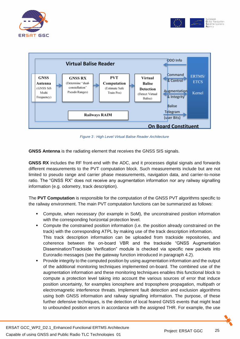
The High Level Architecture of the Virtual Balise reader element in the on-board constituent is
shown in Figure 3. It is worth to remark that this architecture reuses and extends the concepts
introduced in STARS and is compatible with the High Level Functional Architecture presented in
X2RAIL-2 [17].
Project: ERSAT GGC
25 ERSAT GCC_WP2_D2.1_Enhanced Functional ERTMS Architecture
Capable of using GNSS and Public Radio TLC Technologies_01
Figure 3 : High Level Virtual Balise Reader Architecture
GNSS Antenna is the radiating element that receives the GNSS SIS signals.
GNSS RX includes the RF front-end with the ADC, and it processes digital signals and forwards
different measurements to the PVT computation block. Such measurements include but are not
limited to pseudo range and carrier phase measurements, navigation data, and carrier-to-noise
ratio. The “GNSS RX” does not receive any augmentation information nor any railway signalling
information (e.g. odometry, track description).
The PVT Computation is responsible for the computation of the GNSS PVT algorithms specific to
the railway environment. The main PVT computation functions can be summarized as follows:
Compute, when necessary (for example in SoM), the unconstrained position information
with the corresponding horizontal protection level.
Compute the constrained position information (i.e. the position already constrained on the
track) with the corresponding ATPL by making use of the track description information.
This track description information can be uploaded from trackside repositories, and
coherence between the on-board VBR and the trackside “GNSS Augmentation
Dissemination/Trackside Verification” module is checked via specific new packets into
Euroradio messages (see the gateway function introduced in paragraph 4.2).
Provide integrity to the computed position by using augmentation information and the output
of the additional monitoring techniques implemented on-board. The combined use of the
augmentation information and these monitoring techniques enables this functional block to
compute a protection level taking into account the various sources of error that induce
position uncertainty, for examples ionosphere and troposphere propagation, multipath or
electromagnetic interference threats. Implement fault detection and exclusion algorithms
using both GNSS information and railway signalling information. The purpose, of these
further defensive techniques, is the detection of local feared GNSS events that might lead
to unbounded position errors in accordance with the assigned THR. For example, the use

Project: ERSAT GGC
26 ERSAT GCC_WP2_D2.1_Enhanced Functional ERTMS Architecture
Capable of using GNSS and Public Radio TLC Technologies_01
of SIL4 odometry information based on the multi-sensor technology, already available on
the on-board, has been demonstrated as a valid mitigation technique to any residual hazard
associated with GNSS misleading information.
The Virtual Balise Detection (VBD) functional block carries out the following functions:
Compare the GNSS based train position with pre-known virtual balise positions stored in
the on-board track description to declare virtual balise detection
Receive odometry data from ERTMS/ETCS kernel to properly stamp the detected virtual
balise
Provide the following information to the ETCS on-board kernel when a virtual balise is
detected:
o Time / odometer stamp of the detected virtual balise center; this information takes into
account the position of the GNSS Antenna with respect to the front end of the
respective engine with respect to the train orientation
o The detection error associated with the virtual balise detection accuracy
o Balise information (user bits) for the detected virtual balise, stored into an on-board
track description
Guarantee the delivery of virtual balises in the correct sequence
Guarantee Cross-talk protection in accordance with the assigned THR
Ensure Immunity to environmental noise by means of the implementation of robust
detection algorithms
Detect the corruption of User-bits
Dynamically execute run time tests to detect failures in the virtual balise detection function
and notify this anomaly to the ERTMS/ETCS Kernel
Railways RAIM block due to the peculiarities of the railway environment with respect to RF channel
impairments, the Railways RAIM functional block includes the set of cascaded integrity checks to
be executed on-board to cope with GNSS system and local feared events that may have impact
on the GNSS position to be used for detecting the virtual balise.
The first set of these integrity checks can be executed in the GNSS receiver in the pseudo range
domain at the level of the satellite signal individually. The objective of these checks is to isolate
and exclude faulted or suspect code measurements and phase measurements before the next
integrity checks at the level of PVT computation conduct the final check in the position domain. As
the GNSS receiver is not a safe railway component, diagnostic information must also be provided
to the PVT Computation block (that is a safe component) so that it can implement safe periodic run
time checks.
For the remaining set of integrity checks, many studies are still in progress and different possible
CRAIM or ARAIM algorithms have been proposed (e.g. [6] and [7]). In addition, one of these
integrity checks is the odometry cross check that exploits the high precision of the SIL 4 odometry
in a limited spatial interval.
Project: ERSAT GGC
27 ERSAT GCC_WP2_D2.1_Enhanced Functional ERTMS Architecture
Capable of using GNSS and Public Radio TLC Technologies_01
Finally, as far as the implementation of the complete VBR functional block is concerned, it must be
compliant with the CENELEC recommendations about SIL 4 platform. Therefore, at least two
independent GNSS chains, i.e. from the GNSS Antenna to the virtual balise delivery, along with
the correlated information, are required.
Considering the railway environment it is worth to remark here that Virtual Balise Reader Function
shall manage also situations in which GNSS signals are temporarily not available (e.g. tunnels).
As examples of possible VBR design capable of managing this situation, there is the use of external
inputs (e.g. the use of SIL4 odometry information) or additional optional internal sensors (e.g. IMU).
The WP 4 of ERSAT GGC will define the process for the Track Survey and Track Classification,
that, given the GNSS based positioning services performance along the line, will allow to select
which areas are suitable for the location of virtual balises.
Project: ERSAT GGC
28 ERSAT GCC_WP2_D2.1_Enhanced Functional ERTMS Architecture
Capable of using GNSS and Public Radio TLC Technologies_01
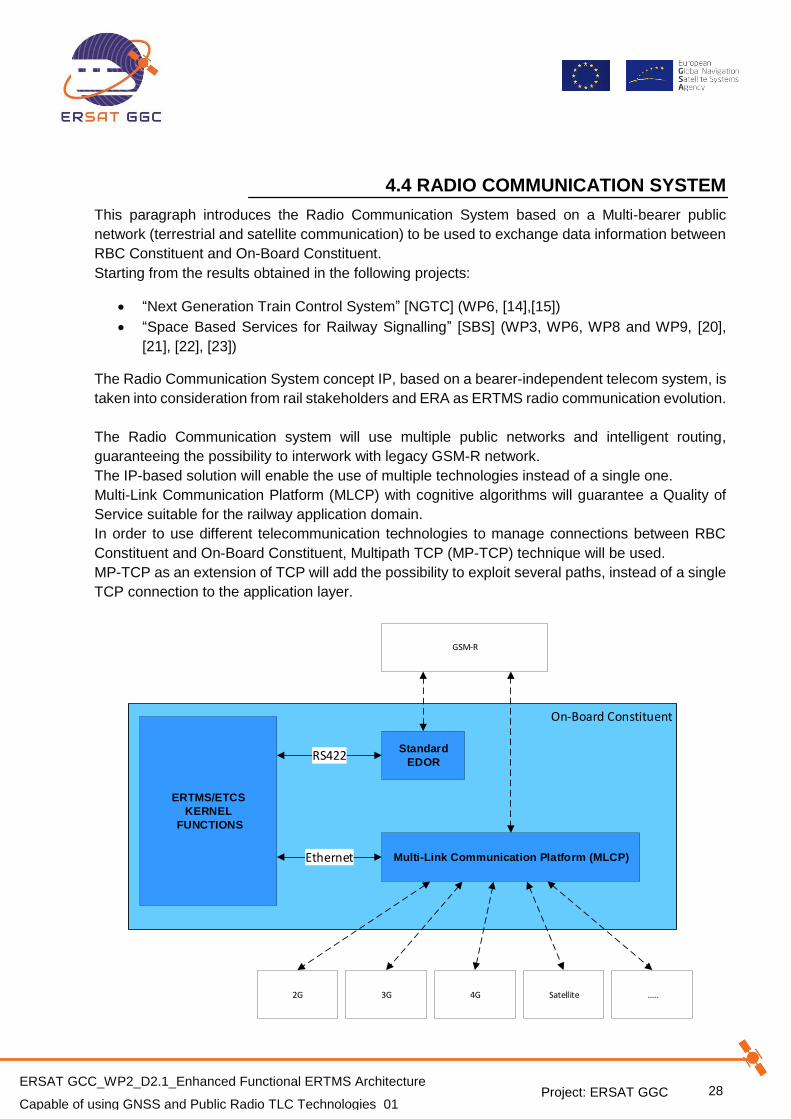
4.4 RADIO COMMUNICATION SYSTEM
This paragraph introduces the Radio Communication System based on a Multi-bearer public
network (terrestrial and satellite communication) to be used to exchange data information between
RBC Constituent and On-Board Constituent.
Starting from the results obtained in the following projects:
“Next Generation Train Control System” [NGTC] (WP6, [14],[15])
“Space Based Services for Railway Signalling” [SBS] (WP3, WP6, WP8 and WP9, [20],
[21], [22], [23])
The Radio Communication System concept IP, based on a bearer-independent telecom system, is
taken into consideration from rail stakeholders and ERA as ERTMS radio communication evolution.
The Radio Communication system will use multiple public networks and intelligent routing,
guaranteeing the possibility to interwork with legacy GSM-R network.
The IP-based solution will enable the use of multiple technologies instead of a single one.
Multi-Link Communication Platform (MLCP) with cognitive algorithms will guarantee a Quality of
Service suitable for the railway application domain.
In order to use different telecommunication technologies to manage connections between RBC
Constituent and On-Board Constituent, Multipath TCP (MP-TCP) technique will be used.
MP-TCP as an extension of TCP will add the possibility to exploit several paths, instead of a single
TCP connection to the application layer.
On-Board Constituent
ERTMS/ETCS
KERNEL
FUNCTIONS
Standard
EDOR
GSM-R
Multi-Link Communication Platform (MLCP)
3G 4G Satellite2G ..
RS422
Ethernet

Project: ERSAT GGC
29 ERSAT GCC_WP2_D2.1_Enhanced Functional ERTMS Architecture
Capable of using GNSS and Public Radio TLC Technologies_01
Figure 4 : Multi-Bearer IP based Communication Network System
The MLCP will follow Euroradio protocol as defined in Subset-037 and the Subset 093 to guarantee
the QoS requirements.
Project: ERSAT GGC
30 ERSAT GCC_WP2_D2.1_Enhanced Functional ERTMS Architecture
Capable of using GNSS and Public Radio TLC Technologies_01
5. ERTMS OPERATIONAL SCENARIOS
5.1 PRELIMINARY ENGINEERING RULES
During this preliminary phase of sharing the following operative scenarios, it has been considered
as initial hypothesis, the use, as well as Virtual Balises, of a limited number of Physical Balises to
be laid within the stations.
This choice has been necessary for:
The initialization of the satellite tracking system (i.e. during the SoM phases) to allow it to
safely discriminate the correct track on which the train is located.
Ensure the capture and processing of telegrams that contain information related to safety.
5.2 VBR INITIALIZED
This paragraph provides the definition of the Virtual Balise Reader status INITIALIZED.
When in the following scenarios is indicated that the status of “VBR “Initialized” is considered,
means that when it can operate under “Nominal” conditions, that is what and It is able to associate
an unique path for its current position (nominal position and related confidence interval), and
provides the Virtual Balises to the ERTMS/ETCS Kernel the Virtual Balises.

Project: ERSAT GGC
31 ERSAT GCC_WP2_D2.1_Enhanced Functional ERTMS Architecture
Capable of using GNSS and Public Radio TLC Technologies_01
5.3 REGISTRATION AND START UP
The following procedure describes the establishment of the Communication Session between the
RBC and the EVC that it starts from the safe connection set-up until the sending of the SOM
Position Report (excluded).
Initial state:
a) The EVC mode is Stand-By (SB) [The desk has been open, or the driver has selected Exit from Shunting].
b) The EVC requests to the driver to enter/revalidate Driver ID.
c) The level stored is Level 2 and the RBC data are valid.
d) The EVC is able to consider train's position as valid, or invalid, or not known at all.
Events:
1. The EVC requests the set-up of a Safe Connection with the RBC.
2. The EVC sends the message Initiation of Communication Session to the RBC [Msg155]
that checks that the number of connected trains is lower than the maximum number of train
connections managed by RBC (configuration parameter).
3. RBC sends the RBC/RIU System Version [Msg32] to the EVC with the request to
acknowledgement (M_ACK=1) and M_VERSION = 32.
4. EVC sends the ACK message [Msg146] to the message [Msg32], and starts the verification
of the version compatibility between trackside and EVC.
5. RBC receives the ACK message [Msg146] and starts a wait timer to receive the message
Session Established [Msg159].
6. EVC verifies the compatibility and sends the Session Established message [Msg159],
including the on-board supported system versions packet [Pkt2] to RBC.
Note:
If the system versions are compatible, the EVC considers the communication session established
and informs the driver.
7. RBC receives the Session Established message [Msg159], terminates the wait timer to
receive the Session Established message [Msg159], and considers the communication
session also established for trackside.
8. GAD/TV starts the handshake to verify GAD/TV Track DB version and VBR Track DB
version (e.g. EVC track database/information).
9. RBC sends:
General Message [Msg24], with acknowledgment request (M_ACK=1), that includes the
request to the validation of the track DB.
General Message [Msg24], with acknowledgment request (M_ACK=1), that include the
packet Position Report Parameters [Pkt58] and the variable M_LOC=0 (now).
10. EVC sends immediately a Position Report message [Msg136] including the Data used by
applications outside the ERTMS/ETCS which communicates if the track DB is received, and
the version is the same, and:

Project: ERSAT GGC
32 ERSAT GCC_WP2_D2.1_Enhanced Functional ERTMS Architecture
Capable of using GNSS and Public Radio TLC Technologies_01
If the GAD/TV Track DB version is the same of VBR track DB version, then the
procedure of start-up proceed from step 11.
If the GAD/TV Track DB version is not the same of VBR track DB version, then the VBR
performs the updating of the track DB and after only the procedure for checking and
verifying the Track DB, will start again from point 8, meanwhile the SoM procedure
proceed from step11 independently.
Note:
The mismatch could be possible because a different version of the GAD/TV and VBR track DBs or
no track DB is uploaded on-board.
Note:
The information that the complete and correct update of the VBR Track DB has been carried out
will be important later to decide if RBC will be able or not to send a movement authorization to the
train, following the receipt of the [Msg132].
11. RBC starts the handshake to configure the EVC (a) when and how often the train has to
ask for a movement authority and (b) when and how often the train position has to be
reported:
RBC sends a General Message [Msg24], with acknowledgment request (M_ACK=1),
that includes the packets Movement Authority Request Parameters [Pkt57] and Position
Report Parameters [Pkt58]
EVC sends the ACK message [Msg146] to RBC
RBC receives the ACK message [Msg146]
12. RBC starts the handshake to provide the National Values to the EVC:
RBC sends a General Message [Msg24], with acknowledgment request (M_ACK=1),
that includes the National Values packet [Pkt3] with variables set in accordance with the
ERTMS Baseline applied and the variable D_VALIDNV set to 32767 (BL3 special value
to enable the immediate use of national values)
EVC sends the ACK message [Msg146] to RBC
RBC receives such a message [Msg146]
Project: ERSAT GGC
33 ERSAT GCC_WP2_D2.1_Enhanced Functional ERTMS Architecture
Capable of using GNSS and Public Radio TLC Technologies_01
5.3.1 ALTERNATIVE PATH
Proposal for future possible discussion
Scope of this paragraph is only to propose a possible change request about how the on-board
handles and checks the Track DB. It is a starting point for further analysis about a possible
alternative way to proceed, because it requires a modification of the SoM flowchart described in
the UNISIG Subset-026.
The idea is to provide that the verification of the DB version be carried out before that the board
considers the communication session to be active, and concurrently with the ERTMS system
version check [event 3 in the previous paragraph]. In case of the Track DB version is different of
the Trackside version, the EVC must stop the start-up procedure and provides to the updating of
the correct Track DB version.
Project: ERSAT GGC
34 ERSAT GCC_WP2_D2.1_Enhanced Functional ERTMS Architecture
Capable of using GNSS and Public Radio TLC Technologies_01
5.4 START OF MISSION IN LEVEL 2 WITH Q_STATUS “KNOWN”
According to [1] UNISIG, “SUBSET-026- System Requirements Specification” Version 3.6.0. §4.11,
in the following scenarios, the EVC can send a SOM Position Report with Q_STATUS=1, if the
train has previously switched in Standby (SB) mode, and the previous status, of stored information,
was set to "Valid”. This behaviour is independent for the presence or not to the CMD.
Other behaviour is possible when the train has previously switched in No Power (NP) mode, and
the status of stored information becomes to “INVALID”. If the train is equipped with a CMD, when
it switches in SB mode, and no cold movement occurred, It is able to re-validated the stored
information, that back “VALID”.
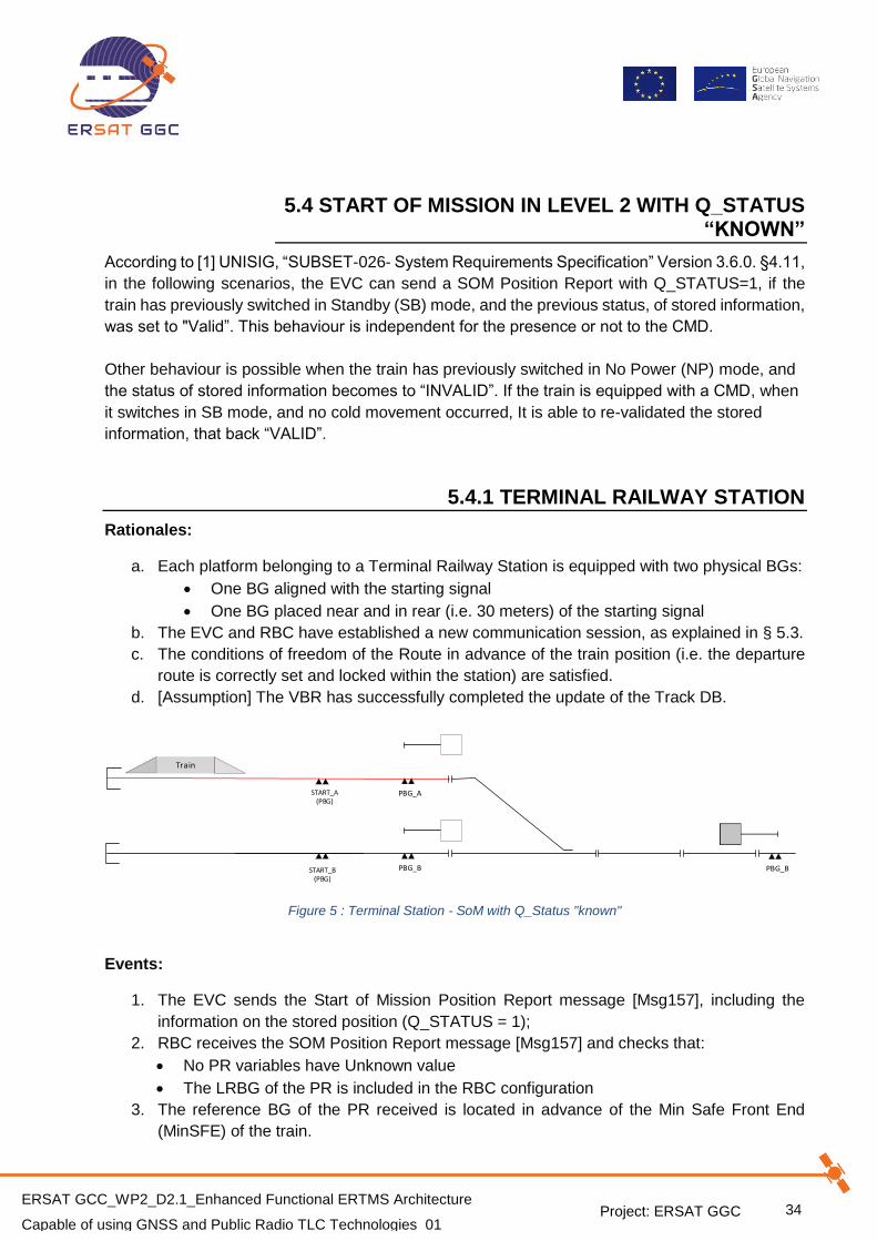
5.4.1 TERMINAL RAILWAY STATION
Rationales:
a. Each platform belonging to a Terminal Railway Station is equipped with two physical BGs:
One BG aligned with the starting signal
One BG placed near and in rear (i.e. 30 meters) of the starting signal
b. The EVC and RBC have established a new communication session, as explained in § 5.3.
c. The conditions of freedom of the Route in advance of the train position (i.e. the departure
route is correctly set and locked within the station) are satisfied.
d. [Assumption] The VBR has successfully completed the update of the Track DB.
START_B(PBG)
START_A(PBG)
PBG_B
Train
PBG_A
PBG_B
Figure 5 : Terminal Station - SoM with Q_Status "known"
Events:
1. The EVC sends the Start of Mission Position Report message [Msg157], including the
information on the stored position (Q_STATUS = 1);
2. RBC receives the SOM Position Report message [Msg157] and checks that:
No PR variables have Unknown value
The LRBG of the PR is included in the RBC configuration
3. The reference BG of the PR received is located in advance of the Min Safe Front End
(MinSFE) of the train.

Project: ERSAT GGC
35 ERSAT GCC_WP2_D2.1_Enhanced Functional ERTMS Architecture
Capable of using GNSS and Public Radio TLC Technologies_01
4. RBC regards the SoM PR as valid, and the GAD/TV sends to the VBR the information to
select the track in not ambiguous way (or an equivalent information which defines the
platform) to the VBR, where the train is localised.
5. VBR is initialized.
6. RBC commands the visualization of the train icon on the RBC HMI Monitor.
7. EVC sends the Validated Train Data message [Msg129] to RBC, including the Position
Report packet [Pkt0] and the Validated train data packet [Pkt11].
8. RBC receives the message [Msg129], checks the data, considers such data as acceptable
and starts the handshake to acknowledge the Train Data:
RBC sends the Acknowledgement of Train Data message [Msg8] with
acknowledgement request (M_ACK = 1)
EVC sends the ACK message [Msg146] to RBC
RBC receives the ACK message [Msg146]
9. The START button is enabled on DMI; the Driver waits to receive from the Dispatcher the
authorization to press it.
10. Driver enters the Train running number, if it is not valid yet.
11. EVC sends a Position Report message [Msg136], including the Train running number
packet [Pkt5].
12. Once authorized by the Dispatcher, the Driver presses the START button.
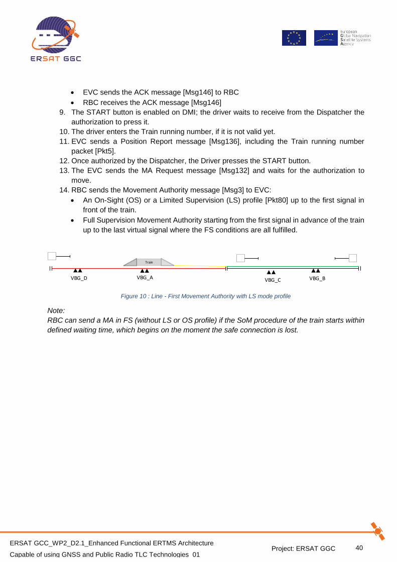
13. The EVC sends the MA Request message [Msg132] and waits for the authorization to
move.
14. RBC sends the MA with Shifted Location Reference message [Msg33] to EVC:
An On-Sight (OS) or a Limited Supervision (LS) profile [Pkt80] up to the first signal in
advance of the train
Full Supervision Movement Authority starting from the first signal in advance of the train
up to the last virtual signal where the FS conditions are all fulfilled
START_B(PBG)
START_A(PBG)
PBG_B
Train
PBG_A
PBG_B
Figure 6 : Terminal Station - First Movement Authority with LS (or OS) mode profile

Project: ERSAT GGC
36 ERSAT GCC_WP2_D2.1_Enhanced Functional ERTMS Architecture
Capable of using GNSS and Public Radio TLC Technologies_01
5.4.2 ALTERNATIVE PATHS
a) The first Radio Block section is not available
The conditions of freedom of the Radio Block Section in advance of the train position are not
satisfied (i.e. it is not possible to set and/or lock the departure route within the station).
In this case, the Driver should not receive the authorization to press the START button on DMI
(operational rule).
If the START button is pressed and the RBC receives the MA Request message [Msg132], the
RBC shall not send any Movement Authority to the EVC, but sends a SR Authorisation with D_SR
set to a minimum distance, sufficient to allow the train movement in SR mode, only after Override
procedure.
Note:
According to [1] UNISIG, “SUBSET-026 - System Requirements Specification” Version 3.6.0.,
chapter 5.4.4, the EVC waits for an answer when the MA Request message is sent.
SR Authorisation sent by RBC is necessary in order to avoid a possible deadlock in the EVC DMI.
b) The VBR has not completed the track DB uploading
The Track DB uploading should take few seconds and it is transparent to the driver and Dispatcher.
In the case that the driver can press the START button, after that, the RBC receives the MA
Request message [Msg132] and:
Shall not send any Movement Authority to the EVC.
Shall send a SR Authorisation with D_SR set to a distance, which allows the train movement
in SR mode only with an Override procedure.
Shall inform the Driver (with a text message) and the Dispatcher (with an alarm on the HMI
Monitor) about the reason of the missed MA;
Note:
According to [1] UNISIG, “SUBSET-026 - System Requirements Specification” Version 3.6.0.,
chapter 5.4.4, the EVC waits for an answer when the MA Request message is sent.
SR Authorisation sent by RBC is necessary in order to avoid a possible deadlock in the EVC DMI.

Project: ERSAT GGC
37 ERSAT GCC_WP2_D2.1_Enhanced Functional ERTMS Architecture
Capable of using GNSS and Public Radio TLC Technologies_01
5.4.3 INTERMEDIATE STATION
Rationales:
a) Each platform belonging to an Intermediate Railway Station is equipped with one physical
BG aligned to each starting signal.
b) The EVC and RBC have established a new communication session, as explained in § 5.3.
c) The conditions of freedom of the Route in advance of the train position (i.e. the departure
route is correctly set and locked within the station) are satisfied.
d) [Assumption] The VBR has successfully completed the update of the Track DB.
START_B(PBG)
START_A(PBG)
PBG_B
Train
PBG_A
PBG_BSTART_C(PBG)
PBG_C
START_D(PBG)
PBG_D
PBG_B
Figure 7 : Intermediate Station - SoM with Q_STATUS "Known"
Events:
1. The EVC sends the Start of Mission Position Report message [Msg157], including the
information on the stored position (Q_STATUS = 1).
2. RBC receives the SOM Position Report message [Msg157] and checks that:
No PR variables have Unknown value.
The LRBG of the PR is included in the RBC configuration.
3. The reference BG of the PR received is located in rear of the Min Safe Front End
(MinSFE) of the train.
4. There is no switch point that may lead to an alternative route, located between the LRBG
and the MaxSFE (with respect to the train orientation).
5. RBC regards the SoM PR as valid, and the GAD/TV sends to the VBR the information to
select the track in not ambiguous way, where the train is localized.
6. VBR is initialized.
7. RBC commands the visualization of the train icon on the RBC HMI Monitor.
8. EVC sends the Validated Train Data message [Msg129] to RBC, including the Position
Report packet [Pkt0] and the validated train data packet [Pkt11].
9. RBC receives such a message [Msg129], checks the data, considers such data as
acceptable and starts the handshake to acknowledge the Train Data:
RBC sends the Acknowledgement of Train Data message [Msg8] with
acknowledgement request (M_ACK = 1).
EVC sends the ACK message [Msg146] to RBC.
RBC receives such a message [Msg146].
10. The START button is enabled on DMI; the driver waits to receive from the Dispatcher the
authorization to press it.

Project: ERSAT GGC
38 ERSAT GCC_WP2_D2.1_Enhanced Functional ERTMS Architecture
Capable of using GNSS and Public Radio TLC Technologies_01
11. Once authorized by the Dispatcher, the Driver presses the START button.
12. The EVC sends the MA Request message [Msg132], and waits for the authorization to
move.
13. RBC sends the Movement Authority message [Msg3] to EVC:
An On-Sight (OS), or a Limited Supervision (LS) profile [Pkt80] up to the first signal in
advance of the train.
Full Supervision Movement Authority starting from the first signal in advance of the train
up to the last virtual signal where the FS conditions are all fulfilled.
START_B(PBG)
START_A(PBG)
PBG_B
Train
PBG_A
PBG_BSTART_C(PBG)
PBG_C
START_D(PBG)
PBG_D
PBG_B
Figure 8 : Intermediate Station - First Movement Authority with LS (or OS) mode profile
5.4.4 ALTERNATIVE PATHS
a) The first Radio Block Section is not available
The same described in §5.4.2, point a).
b) The train proceeds in the opposite direction with respect to the previous Mission
The train proceeds in the opposite direction with respect to the previous Mission (i.e. when arriving
on the station platform).
If the EVC reports a known position to RBC, the scenario is the same described in § 5.4.3.
If the EVC reports an unknown position to RBC, the scenario is the same described in § 5.6.6.

Project: ERSAT GGC
39 ERSAT GCC_WP2_D2.1_Enhanced Functional ERTMS Architecture
Capable of using GNSS and Public Radio TLC Technologies_01
5.5 LINE
This scenario represents a degraded case with respect to the nominal one, where the train would
not perform a SoM along the line. This would happen only due to a fault and after the previous
Communication Session has been closed.
The line is equipped only with virtual balises (i.e VBG_A).
Rationales:
a) The Driver has performed an EoM along the line.
b) The previous communication session is considered as closed due a Safe Connection
Failure.
c) The EVC and RBC have established a new communication session, as explained in § 5.3.
d) RBC considers the line track section as occupied by a not connected train (this
information is not related to the physical occupation).
e) RBC has stored, during the previous mission, both NID_OPERATIONAL and
NID_ENGINE of the train, and then RBC knows that the direction of train is the same of
the previous mission.
f) [Assumption] The VBR has successfully completed the update of the Track DB.
Train
VBG_A VBG_BVBG_CVBG_DVBG_E
Figure 9 : Line - SoM in Level 2 with Q_STATUS "Known"
Events:
1. The EVC sends the Start of Mission Position Report message [Msg157], including the
information on the stored position (Q_STATUS = 1).
2. RBC receives the SOM Position Report message [Msg157] and checks that:
No PR variables have Unknown value.
The LRBG of the PR is included in the RBC configurations.
3. The reference BG of the PR received, is located in rear the Min Safe Front End (MinSFE)
of the train.
4. RBC regards the SoM PR as valid and the GAD/TV sends the information to select the track
in not ambiguous way to the VBR, where the train is localised.
5. VBR is initialized.
6. RBC commands the visualization of the train icon on the RBC HMI Monitor.
7. EVC sends the Validated Train Data message [Msg129] to RBC, including the Position
Report packet [Pkt0] and the Validated train data packet [Pkt11].
8. RBC receives the message [Msg129], checks the data, considers such data as acceptable
and starts the handshake to acknowledge the Train Data:
RBC sends the Acknowledgement of Train Data message [Msg8] with
acknowledgement request (M_ACK = 1)
Project: ERSAT GGC
40 ERSAT GCC_WP2_D2.1_Enhanced Functional ERTMS Architecture
Capable of using GNSS and Public Radio TLC Technologies_01
EVC sends the ACK message [Msg146] to RBC
RBC receives the ACK message [Msg146]
9. The START button is enabled on DMI; the driver waits to receive from the Dispatcher the
authorization to press it.
10. The driver enters the Train running number, if it is not valid yet.
11. EVC sends a Position Report message [Msg136], including the Train running number
packet [Pkt5].
12. Once authorized by the Dispatcher, the Driver presses the START button.
13. The EVC sends the MA Request message [Msg132] and waits for the authorization to
move.
14. RBC sends the Movement Authority message [Msg3] to EVC:
An On-Sight (OS) or a Limited Supervision (LS) profile [Pkt80] up to the first signal in
front of the train.
Full Supervision Movement Authority starting from the first signal in advance of the train
up to the last virtual signal where the FS conditions are all fulfilled.
Train
VBG_A VBG_BVBG_CVBG_D
Figure 10 : Line - First Movement Authority with LS mode profile
Note:
RBC can send a MA in FS (without LS or OS profile) if the SoM procedure of the train starts within
defined waiting time, which begins on the moment the safe connection is lost.

Project: ERSAT GGC
41 ERSAT GCC_WP2_D2.1_Enhanced Functional ERTMS Architecture
Capable of using GNSS and Public Radio TLC Technologies_01
5.6 START OF MISSION IN LEVEL 2 WITH Q_STATUS “UNKNOWN”
5.6.1 TERMINAL RAILWAY STATION
a) SoM with a train position approximation
This scenario describes a situation where it is possible to associate the NID_ENGINE with the
Track Section, previously occupied by Train. This association can be used to discriminate the Track
where the train is located.
Rationales:
a) Each platform belonging to a Terminal Railway Station is equipped with two physical BGs:
One BG aligned with the starting signal
One BG placed near and in rear (i.e. 30 meters) of the starting signal
b) The EVC and RBC have established a new communication session, as explained in § 5.3.
c) RBC considers the platform occupied by a not connected train (this information is not related
to the physical occupation).
d) The conditions of freedom of the Route in advance of the train position (i.e. the departure
route is correctly set and locked within the station) are satisfied.
e) RBC has stored the association between Nid_engine and Track section of the train, and
then RBC knowns the direction of the train.
f) [Assumption] The VBR has successfully completed the update of the Track DB.
START_B(PBG)
START_A(PBG)
PBG_B
Train
PBG_A
PBG_B
Figure 11 : Terminal Station - SoM with Q_STATUS = "UnKnown"
Events:
1. The EVC sends the Start of Mission Position Report message [Msg157], including the
information Q_STATUS = 0/2.
2. RBC considers the SoM PR Invalid/unknown, and then RBC considers the train Not
Localized.
3. RBC cannot visualize any train icon on the RBC HMI Monitor.
4. RBC starts the handshake to inform to EVC that the train has been accepted:
Project: ERSAT GGC
42 ERSAT GCC_WP2_D2.1_Enhanced Functional ERTMS Architecture
Capable of using GNSS and Public Radio TLC Technologies_01
RBC sends Train Accepted message [Msg41] to EVC with [M_ACK = 1]
EVC sends the ACK message [Msg146] to RBC
5. EVC sends the Validated Train Data message [Msg129] to RBC, including the Position
Report packet [Pkt0] and the validated train data packet [Pkt11].
6. RBC receives the message [Msg129], checks the data, considers such data as acceptable,
and starts the handshake to acknowledge the Train Data:
RBC sends the Acknowledgement of Train Data message [Msg8] with acknowledgement
request (M_ACK = 1)
EVC sends the ACK message [Msg146] to RBC
RBC receives the ACK message [Msg146]
7. The START button is enabled on DMI; the driver waits to receive from the Dispatcher the
authorization to press it.
8. The driver enters the Train running number, if it is not valid yet.
9. EVC sends a Position Report message [136], including the Train running number packet
[Pkt5].
10. RBC checks that:
A not connected train is present on the track section
The association between Nid_engine stored and Nid_engine received from the EVC is
the same
11. RBC regards the position of the train as “APPROXIMATE”.
12. GAD/TV sends the information to select the track in not ambiguous way (or an equivalent
information which defines the platform) to the VBR, where the train position is
“APPROXIMATE”.
13. VBR is initialized.
14. Once authorized by Dispatcher, the Driver presses the START button.
15. The EVC sends the MA Request message [Msg132] and waits for the authorization to
move.
16. RBC sends the SR Authorization message [Msg2] to EVC with D_SR=infinite and including
the List of Balises in SR Authority packet [Pkt63] including Balise of the current RBS plus
the Balise of the RBS in advance.
17. EVC starts to move in SR Mode.
18. The Train detects the first Physical BG (i.e. PBG_A in Figure 11).
19. RBC regards the EVC as localized and commands the visualization of the train icon on the
RBC HMI Monitor.
20. RBC sends the Movement Authority message [Msg3] to EVC.
An On-Sight (OS) or a Limited Supervision (LS) profile [Pkt80] up to the first signal in
front of the train
Full Supervision Movement Authority starting from the first signal in advance of the train
up to the last virtual signal where the FS conditions are all fulfilled
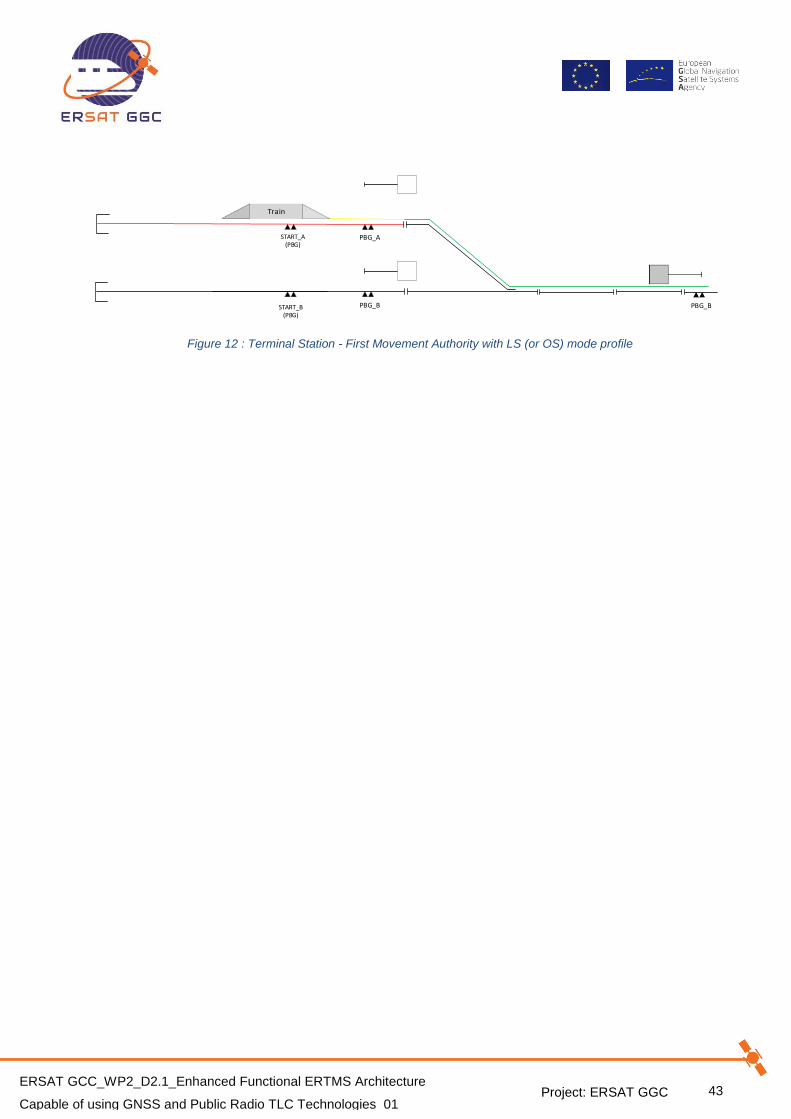
Project: ERSAT GGC
43 ERSAT GCC_WP2_D2.1_Enhanced Functional ERTMS Architecture
Capable of using GNSS and Public Radio TLC Technologies_01
START_B(PBG)
START_A(PBG)
PBG_B
Train
PBG_A
PBG_B
Figure 12 : Terminal Station - First Movement Authority with LS (or OS) mode profile

Project: ERSAT GGC
44 ERSAT GCC_WP2_D2.1_Enhanced Functional ERTMS Architecture
Capable of using GNSS and Public Radio TLC Technologies_01
5.6.2 TMS-RBC CONNECTION IS AVAILABLE
Rationales:
a) Each platform belonging to a Terminal Railway Station is equipped with two physical BGs:
One BG aligned with the starting signal
One BG placed near and in rear (i.e. 30 meters) of the starting signal
e) The EVC and RBC have established a new communication session, as explained in § 5.3.
b) The conditions of freedom of the Route in advance of the train position (i.e. the departure
route is correctly set and locked within the station) are satisfied.
c) RBC is not able to associate the track with train NID_ENGINE.
d) [Assumption] The VBR has successfully completed the update of the Track DB.
e) TMS-RBC connection is available.
Events:
1. The EVC sends the Start of Mission Position Report message [Msg157], including the
information Q_STATUS = 0/2.
2. RBC considers the SoM PR Invalid/unknown, then, RBC considers the train Not Localized.
3. RBC cannot visualize any train icon on the RBC HMI Monitor.
4. RBC starts the handshake to inform to EVC that the train has been accepted:
RBC sends Train Accepted message [Msg41] to EVC with [M_ACK = 1]
EVC sends the ACK message [Msg146] to RBC
5. EVC sends the Validated Train Data message [Msg129] to RBC, including the Position
Report packet [Pkt0] and the validated train data packet [Pkt11].
6. RBC receives the message [Msg129], checks the data, considers such data as acceptable
and starts the handshake to acknowledge the Train Data:
RBC sends the Acknowledgement of Train Data message [Msg8] with acknowledgement
request (M_ACK = 1)
EVC sends the ACK message [Msg146] to RBC
RBC receives the ACK message [Msg146]
7. The START button is enabled on DMI; the driver waits to receive from the Dispatcher the
authorization to press it.
8. The driver enters the Train running number, if it is not valid yet.
9. EVC sends a Position Report message [136], including the Train running number packet
[Pkt5].
10. RBC checks that:
A NID_OPERATIONAL received by the TMS is the same reported by the EVC
The track section associated to the NID_OPERATIONAL received by the TMS is
considered, by the RBC, occupied by a not connected train (this information is
independent from the physical occupancy of the track)
11. RBC notifies to GAD/TV the information related to the not ambiguous train position.
12. GAD/TV sends the information to select the track in not ambiguous way (or an equivalent
information which defines the platform) to the VBR, according to the information received
by the TMS.
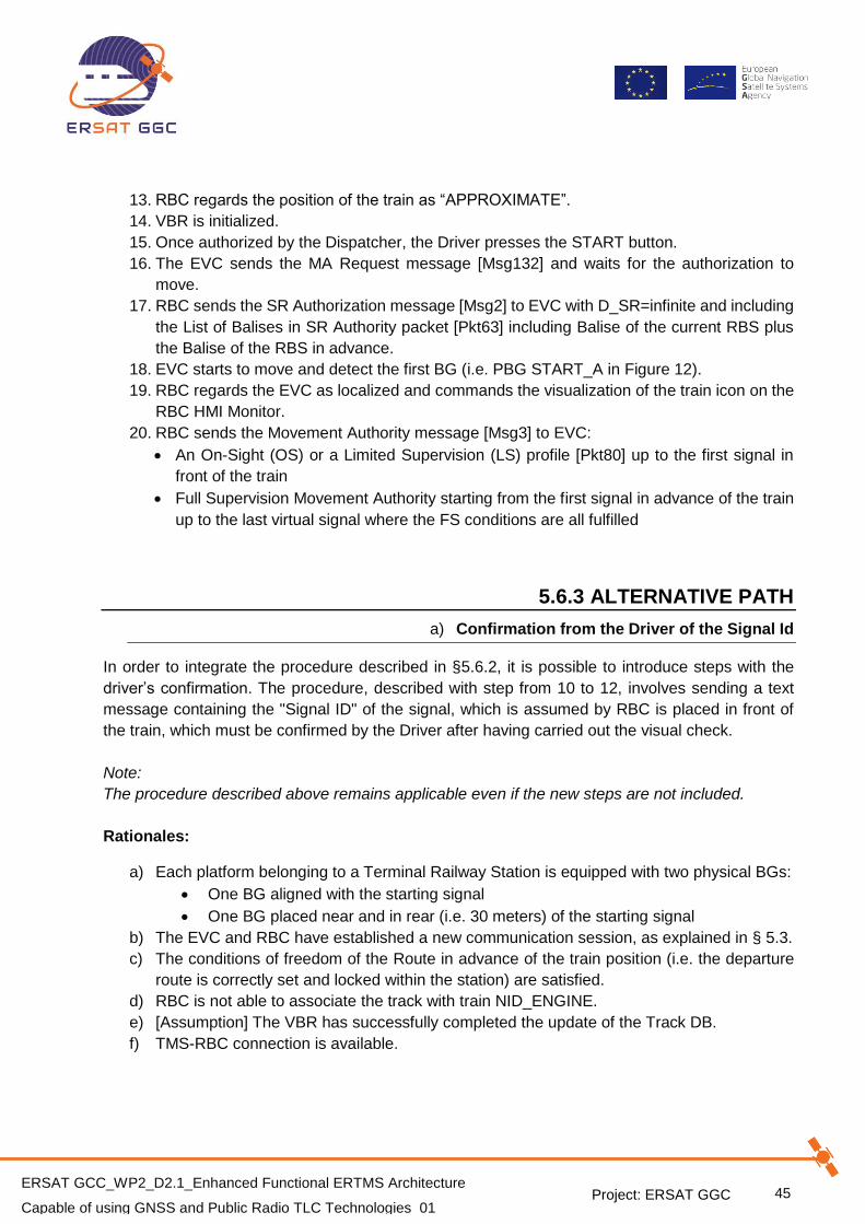
Project: ERSAT GGC
45 ERSAT GCC_WP2_D2.1_Enhanced Functional ERTMS Architecture
Capable of using GNSS and Public Radio TLC Technologies_01
13. RBC regards the position of the train as “APPROXIMATE”.
14. VBR is initialized.
15. Once authorized by the Dispatcher, the Driver presses the START button.
16. The EVC sends the MA Request message [Msg132] and waits for the authorization to
move.
17. RBC sends the SR Authorization message [Msg2] to EVC with D_SR=infinite and including
the List of Balises in SR Authority packet [Pkt63] including Balise of the current RBS plus
the Balise of the RBS in advance.
18. EVC starts to move and detect the first BG (i.e. PBG START_A in Figure 12).
19. RBC regards the EVC as localized and commands the visualization of the train icon on the
RBC HMI Monitor.
20. RBC sends the Movement Authority message [Msg3] to EVC:
An On-Sight (OS) or a Limited Supervision (LS) profile [Pkt80] up to the first signal in
front of the train
Full Supervision Movement Authority starting from the first signal in advance of the train
up to the last virtual signal where the FS conditions are all fulfilled
5.6.3 ALTERNATIVE PATH
a) Confirmation from the Driver of the Signal Id
In order to integrate the procedure described in §5.6.2, it is possible to introduce steps with the
driver’s confirmation. The procedure, described with step from 10 to 12, involves sending a text
message containing the "Signal ID" of the signal, which is assumed by RBC is placed in front of
the train, which must be confirmed by the Driver after having carried out the visual check.
Note:
The procedure described above remains applicable even if the new steps are not included.
Rationales:
a) Each platform belonging to a Terminal Railway Station is equipped with two physical BGs:
One BG aligned with the starting signal
One BG placed near and in rear (i.e. 30 meters) of the starting signal
b) The EVC and RBC have established a new communication session, as explained in § 5.3.
c) The conditions of freedom of the Route in advance of the train position (i.e. the departure
route is correctly set and locked within the station) are satisfied.
d) RBC is not able to associate the track with train NID_ENGINE.
e) [Assumption] The VBR has successfully completed the update of the Track DB.
f) TMS-RBC connection is available.

Project: ERSAT GGC
46 ERSAT GCC_WP2_D2.1_Enhanced Functional ERTMS Architecture
Capable of using GNSS and Public Radio TLC Technologies_01
Events:
1. The EVC sends the Start of Mission Position Report message [Msg157], including the
information Q_STATUS = 0/2.
2. RBC considers the SoM PR Invalid/unknown, then, RBC considers the train Not Localized.
3. RBC cannot visualize any train icon on the RBC HMI Monitor.
4. RBC starts the handshake to inform to EVC that the train has been accepted:
RBC sends Train Accepted message [Msg41] to EVC with [M_ACK = 1]
EVC sends the ACK message [Msg146] to RBC
5. EVC sends the Validated Train Data message [Msg129] to RBC, including the Position
Report packet [Pkt0] and the validated train data packet [Pkt11].
6. RBC receives the message [Msg129], checks the data, considers such data as acceptable
and starts the handshake to acknowledge the Train Data:
RBC sends the Acknowledgement of Train Data message [Msg8] with acknowledgement
request (M_ACK = 1)
EVC sends the ACK message [Msg146] to RBC
RBC receives the ACK message [Msg146]
7. The START button is enabled on DMI; the driver waits to receive from the Dispatcher the
authorization to press it.
8. The driver enters the Train running number, if it is not valid yet.
9. EVC sends a Position Report message [136], including the Train running number packet
[Pkt5].
10. RBC checks that:
A NID_OPERATIONAL received by the TMS is the same reported by the EVC
The track section associated to the NID_OPERATIONAL received by the TMS is
considered occupied by RBC (this information is independent from the physical
occupancy of the track)
11. RBC sends a General Message [Msg24] including the Packet for sending plain text
messages [Pkt72] with the following information:
A message with the “Signal Id” associated to the Track is sent to the VBR
A request of confirmation from the driver
12. The driver confirms the Text Message on the DMI.
13. EVC sends the Text Message Acknowledged by Driver message [Msg158].
14. RBC notifies to GAD/TV the information related to the not ambiguous train position.
15. GAD/TV sends the information to select the track in not ambiguous way (or an equivalent
information which defines the platform) to the VBR, according to the information received
by the TMS.
16. RBC regards the position of the train as “APPROXIMATE”.
17. VBR is initialized.
18. Once authorized by the Dispatcher, the Driver presses the START button.
19. The EVC sends the MA Request message [Msg132] and waits for the authorization to
move.

Project: ERSAT GGC
47 ERSAT GCC_WP2_D2.1_Enhanced Functional ERTMS Architecture
Capable of using GNSS and Public Radio TLC Technologies_01
20. RBC sends the SR Authorization message [Msg2] to EVC with D_SR=infinite and including
the List of Balises in SR Authority packet [Pkt63] including Balise of the current RBS plus
the Balise of the RBS in advance.
21. EVC starts to move and detect the first BG (i.e. PBG_A in Figure 12).
22. RBC regards the EVC as localized and commands the visualization of the train icon on the
RBC HMI Monitor.
23. RBC sends the Movement Authority message [Msg3] to EVC:
An On-Sight (OS) or a Limited Supervision (LS) profile [Pkt80] up to the first signal in
front of the train
Full Supervision Movement Authority starting from the first signal in advance of the train
up to the last virtual signal where the FS conditions are all fulfilled
5.6.4 TMS-RBC CONNECTION IS NOT AVAILABLE
Rationales:
a) Each platform belonging to a Terminal Railway Station is equipped with two physical BGs:
One BG aligned with the starting signal
One BG placed near and in rear (i.e. 30 meters) of the starting signal
b) The EVC and RBC have established a new communication session, as explained in § 5.3.
c) The conditions of freedom of the Route in advance of the train position (i.e. the departure
route is correctly set and locked within the station) are satisfied.
d) RBC is not able to associate the track with train NID_ENGINE.
e) [Assumption] The VBR has successfully completed the update of the Track DB.
Events:
1. The EVC sends the Start of Mission Position Report message [Msg157], including the
information Q_STATUS = 0/2.
2. RBC considers the SoM PR Invalid/unknown, and then RBC considers the train Not
Localized.
3. RBC cannot visualize any train icon on the RBC HMI Monitor.
4. RBC starts the handshake to inform to EVC that the train has been accepted:
RBC sends Train Accepted message [Msg41] to EVC with [M_ACK = 1]
EVC sends the ACK message [Msg146] to RBC
5. EVC sends the Validated Train Data message [Msg129] to RBC, including the Position
Report packet [Pkt0] and the Validated Train Data packet [Pkt11].
6. RBC receives the message [Msg129], checks the data, considers such data as acceptable
and starts the handshake to acknowledge the Train Data:
RBC sends the Acknowledgement of Train Data message [Msg8] with acknowledgement
request (M_ACK = 1)
EVC sends the ACK message [Msg146] to RBC
RBC receives the ACK message [Msg146]

Project: ERSAT GGC
48 ERSAT GCC_WP2_D2.1_Enhanced Functional ERTMS Architecture
Capable of using GNSS and Public Radio TLC Technologies_01
7. The START button is enabled on DMI; the driver waits to receive from the Dispatcher the
authorization to press it.
8. The Driver enters the Train running number, if it is not valid yet.
9. EVC sends a Position Report message [Msg136], including the Train running number
packet [Pkt5].
10. Dispatcher authorises the Driver to start the procedure of OVERRIDE.
11. Once authorized, the Driver starts the procedure of OVERRIDE.
12. EVC starts to move in SR Mode, and detect the first BG (i.e. PBG_A).
13. VBR is initialized.
14. RBC regards the EVC as localized and commands the visualization of the train icon on the
RBC HMI Monitor.
15. RBC sends the Movement Authority message [Msg3] to EVC:
An On-Sight (OS) or a Limited Supervision (LS) profile [Pkt80] up to the first signal in
front of the train
Full Supervision Movement Authority starting from the first signal in advance of the train
up to the last virtual signal where the FS conditions are all fulfilled
START_B(PBG)
START_A(PBG)
PBG_B
Train
PBG_A
PBG_B
Figure 13 : Terminal Station - First Movement Authority with LS (or OS) mode profile
5.6.5 ALTERNATIVE PATH
a) Train position approximation with command from Dispatcher
Rationales:
a) Each platform belonging to a Terminal Railway Station is equipped with two physical BGs:
One BG aligned with the starting signal
One BG placed near and in rear (i.e. 30 meters) of the starting signal
b) The EVC and RBC have established a new communication session, as explained in § 5.3.
c) The conditions of freedom of the Route in advance of the train position (i.e. the departure
route is correctly set and locked within the station) are satisfied.
d) RBC is not able to associate the track with train NID_ENGINE.
e) A command to the Dispatcher to set track in not ambiguous way is available.
f) [Assumption] The VBR has successfully completed the update of the Track DB.
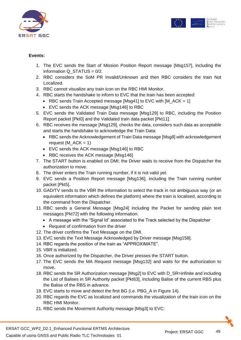
Project: ERSAT GGC
49 ERSAT GCC_WP2_D2.1_Enhanced Functional ERTMS Architecture
Capable of using GNSS and Public Radio TLC Technologies_01
Events:
1. The EVC sends the Start of Mission Position Report message [Msg157], including the
information Q_STATUS = 0/2.
2. RBC considers the SoM PR Invalid/Unknown and then RBC considers the train Not
Localized.
3. RBC cannot visualize any train icon on the RBC HMI Monitor.
4. RBC starts the handshake to inform to EVC that the train has been accepted:
RBC sends Train Accepted message [Msg41] to EVC with [M_ACK = 1]
EVC sends the ACK message [Msg146] to RBC
5. EVC sends the Validated Train Data message [Msg129] to RBC, including the Position
Report packet [Pkt0] and the Validated train data packet [Pkt11].
6. RBC receives the message [Msg129], checks the data, considers such data as acceptable
and starts the handshake to acknowledge the Train Data:
RBC sends the Acknowledgement of Train Data message [Msg8] with acknowledgement
request (M_ACK = 1)
EVC sends the ACK message [Msg146] to RBC
RBC receives the ACK message [Msg146]
7. The START button is enabled on DMI; the Driver waits to receive from the Dispatcher the
authorization to move.
8. The driver enters the Train running number, if it is not valid yet.
9. EVC sends a Position Report message [Msg136], including the Train running number
packet [Pkt5].
10. GAD/TV sends to the VBR the information to select the track in not ambiguous way (or an
equivalent information which defines the platform) where the train is localised, according to
the command from the Dispatcher.
11. RBC sends a General Message [Msg24] including the Packet for sending plain text
messages [Pkt72] with the following information:
A message with the “Signal Id” associated to the Track selected by the Dispatcher
Request of confirmation from the driver
12. The driver confirms the Text Message on the DMI.
13. EVC sends the Text Message Acknowledged by Driver message [Msg158].
14. RBC regards the position of the train as “APPROXIMATE”.
15. VBR is initialized.
16. Once authorized by the Dispatcher, the Driver presses the START button.
17. The EVC sends the MA Request message [Msg132] and waits for the authorization to
move.
18. RBC sends the SR Authorization message [Msg2] to EVC with D_SR=infinite and including
the List of Balises in SR Authority packet [Pkt63], including Balise of the current RBS plus
the Balise of the RBS in advance.
19. EVC starts to move and detect the first BG (i.e. PBG_A in Figure 14).
20. RBC regards the EVC as localized and commands the visualization of the train icon on the
RBC HMI Monitor.
21. RBC sends the Movement Authority message [Msg3] to EVC:

Project: ERSAT GGC
50 ERSAT GCC_WP2_D2.1_Enhanced Functional ERTMS Architecture
Capable of using GNSS and Public Radio TLC Technologies_01
An On-Sight (OS) or a Limited Supervision (LS) profile [Pkt80] up to the first signal in
front of the train
Full Supervision Movement Authority starting from the first signal in advance of the train
up to the last virtual signal where the FS conditions are all fulfilled
START_B(PBG)
START_A(PBG)
PBG_B
Train
PBG_A
PBG_B
Figure 14 : Terminal Station - First Movement Authority with LS (or OS) mode profile

Project: ERSAT GGC
51 ERSAT GCC_WP2_D2.1_Enhanced Functional ERTMS Architecture
Capable of using GNSS and Public Radio TLC Technologies_01
5.6.6 INTERMEDIATE RAILWAY STATION
Rationales:
a) Each platform belonging to an Intermediate Railway Station is equipped with one physical
BG aligned to each starting signal.
b) The EVC and RBC have established a new communication session, as explained in § 5.3.
c) The conditions of freedom of the Route in advance of the train position (i.e. the departure
route is correctly set and locked within the station) are satisfied.
d) [Assumption] The VBR has successfully completed the update of the Track DB.
Event:
The scenario is the same described in § 5.6.1.
5.6.7 LINE
This scenario represents a degraded case with respect to the nominal one, where the train would
not perform a SoM along the line. This would happen only due to a fault and after the previous
Communication Session has been closed.
The line is equipped only with virtual balises (i.e VBG_A).
Rationales:
a) The Driver has performed an EoM along the line.
b) The communication session is considered as closed due a Safe Connection Failure.
c) The EVC and RBC have established a new communication session, as explained in § 5.3.
d) RBC considers the line track section as occupied by a not connected train (this information
is not related to the physical occupation).
e) [Assumption] The VBR has successfully completed the update of the Track DB.
Train
VBG_A VBG_BVBG_CVBG_DVBG_E
Figure 15 : Line - SoM with Q_STATUS = "UnKnown"
Events scenario are the same described in §5.6.1, with the following exception:
EVC starts to move and detect the first VBG (i.e. VBG_A in Figure 15).
Project: ERSAT GGC
52 ERSAT GCC_WP2_D2.1_Enhanced Functional ERTMS Architecture
Capable of using GNSS and Public Radio TLC Technologies_01
CONCLUSIONS
In the frame of the WP 2 of the ERSAT GGC Project, the Enhanced ERTMS Functional
Architecture, suitable for the introduction of the GNSS technology and the Virtual Balise concept,
and for the integration of the IP based Public Mobile Radio Networks has been analysed.
As a continuation of the previous research projects (ERSAT-EAV, NGTC, STARS, RHINOS, SBS,
etc.), the Enhanced ERTMS Functional Architecture has been developed and consolidated; the
specification of the proposed Functional Architecture has been produced in the current document.
In addition, the strategy for guaranteeing the backward compatibility with existing ERTMS systems,
for minimizing the impact on the current ERTMS procedures, and for avoiding the introduction of
criticality with respect to the suppliers of ERTMS Technology, has been evaluated with positive
results.
In particular, the proposed Enhanced ERTMS Functional Architecture includes:
• The functional description of the required new functional blocks at the level of On-Board
and RBC constituents;
• The identification and the functional description of the new interfaces;
• The main ERTMS procedures affected by the introduction of such new functionalities;
• The signalling mitigations required for coping with hazards introduced by the GNSS based
Virtual Balise detection.
The Enhanced ERTMS Functional Architecture developed in the current document has been object
of the Safety Analysis in the frame of WP3.1 of the ERSAT GGC Project, and will be furtherly
evaluated and assessed during the WP3.2 and WP5 of ERSAT GGC.
Additionally, in the WP2.1 or ERSAT GGC the specification of Functional and Non Functional Tests
applicable to the Enhanced ERTMS Functional Architecture will be developed.
These steps will lead to the certification process of the satellite assets to allow the ERTMS to
operate seamlessly with Virtual Balises, and represent a fundamental contribution to the roadmap
of the ERTMS for the adoption of the EGNSS satellite technology and the Public Radio TLC
Technologies.

Project: ERSAT GGC
53 ERSAT GCC_WP2_D2.1_Enhanced Functional ERTMS Architecture
Capable of using GNSS and Public Radio TLC Technologies_01
REFERENCES
[1] UNISIG, “Subset-036 - FFFIS for Eurobalise”, version 3.0.0.
[2] UNISIG, “Subset-041 - Performance Requirements for Interoperability”, version 3.1.0.
[3] UNISIG, “Subset-026 - System Requirements Specification”, version 3.4.0.
[4] UNISIG, “Subset-040 - Dimensioning and Engineering rules”, version 3.3.0.
[5] UNISIG, “Subset-091 - Safety Requirements for the Technical Interoperability of ETCS in
Levels 1&2”, version 3.2.0.
[6] S. Hewitson and J. Wang. GNSS Receiver Autonomous Integrity Monitoring (RAIM)
Performance Analysis. GPS Solutions, 10(3):155–170, 2006.
[7] RHINOS project. D11.2 - Initial description of the Integrity Architecture. 2017.
[8] CENELEC EN 50159, 2010-09-01.
[9] ERSAT GGC _WP2_KO_MoM_01.
[10] REGULATIONS of COMMISSION REGULATION (EU) 2016/919 of 27 May 2016, On the
technical specification for interoperability relating to the ‘control-command and signalling’
subsystems of the rail system in the European Union, 16-05-2016
[11] DIRECTIVE 2008/57/EC OF THE EUROPEAN PARLIAMENT AND OF THE COUNCIL of 17
June 2008, on the interoperability of the rail system within the Community, 18-07-2008
[12] Technical Specification for Interoperability relating to the ‘control-command and signalling’
subsystems of the rail system in the European Union, ERA/ERTMS/034171 – EN, 23/08/2010
[13] NGTC project, D7.1 – Study of GNSS introduction in Rail, State of the Art Study and Adoption
Roadmap Proposal
[14] NGTC project, D6.6 - Results of evaluation
[15] NGTC project, D6.7 - Results of the studies
[16] STARS project, D5.3 EGNSS Target Performances to meet railway safety requirements
[17] X2RAIL-2 X2R2-TSK3.2-T-ANS-003-04, High Level Functional Architecture suitable for the
introduction of the Virtual Balise Concept.
[18] X2Rail-2 project - X2R2-TSK3.2-T-CAI-001-05-
State_of_the_Art_using_GNSS_for_train_positioning.
[19] NGTC project, Work Package 7, D7, NGTC-WP7-D-DAP-068-01_C-
ESA_Principles_16100701.
[20] SBS project, D3 – User Requirements
[21] SBS project, D6 – System Requirements Document
[22] SBS project, D8 – Service Definition Document
[23] SBS project, D9 – System Architecture/s