ersa ir 500 a smt/bga rework system - granasat · ersa ir 500 a smt/bga rework system . contents...
TRANSCRIPT

Instructor: Víctor Burgos González
Prof. Andrés Roldán Aranda
4º Bachelor Degree in
Telecommunications Engineering
ERSA IR 500 A
SMT/BGA Rework
System

Contents
1.- Introduction 2.- Functional elements 3.- Soldering 4.- Desoldering Appendix : Safety Instructions

1.- Introduction
The aim of these presentation is to provide you with information
on the application of this machine and its correct use.
We are going to use this machine once the machine has been
installed in the lab. If you adquire one of this, you should read the
Operating Instructions(NAS) in order to know the first steps that
you have to take.
It’s mandatory have the knowledge about the precaution (read
appendix) that you have to have.
BGA technology

1.- Introduction
Lower heater
Upper heater
Temperature control
and display
Temperature
Sensor
Vacumm pipe
Vacumm
actuator
(by hand)
Laser Pointer

1.- Introduction
Upper IR power emitter 1 x 200 W (emitter surface 60 x 60 mm)
Lower IR power emitter 1 x 400 W (emitter surface 120 x 120 mm)
Total system power 600 W
Wavelength of IR emitter 2 - 8 µm
Power supply 230 VAC 50Hz (115VAC 60 Hz)
Fuse 3.15 AT (6.3AT)
Equipment class 1
Display 7-segment display
Operation Potentiometer
Connecting cable approx. 2 m
Weight approx. 7 kg
Increase in temperature during process between 0.3 and 1.5 K/s
Temperature recording system NiCrNi thermocouple (K type)
Positioning Laser class II
Footprint 300 x 380 mm (W x D)
Total height 165 - 230 mm
Maximum lift 65 mm
Working distance from upper emitter 15 - 40 mm
max. working depth approx. 170 mm
Technical Specifications

2.- Functional elements
Display
The machine is equipped with 2 separate
heating zones: upper and lower heater. The
energy level of each one is controlled using
two potentiometers
The LED indicator lights up via the left
potentiometer as soon as the preset
temperature has been reached.(The duty cycle
of the upper heater is variable, the right LED
indicates the pulse frequency.)
In normal operating mode, the actual
temperature measured at the temperature
sensor is continuously displayed.
Lower heater control
Upper heater control

2.- Functional elements
Turbo button
The highest available energy level in the lower
heater is activated for 60 seconds. During this
working step the turbo button lights up red.
During this time there is no temperature
control.
Laser pointer
The laser positioning aid serves to set up
components prior to the rework process.
Ensure that the laser point on the component
should be in the same position of the operating
point of the vacuum pipette which is in the
centre of the radiant heater.

2.- Functional elements
Vacuum pipette
The vacuum pipette helps remove the desoldered component from the printed circuit board, while the vaccum is active, just before the solder melts.
Aperture system
The aperture system may be adjusted using
the knurled nuts so that IR radiation only
strikes components that are to be desoldered.
We have two distances that can be changes
(Square), depends on the size of the BGA. The
range of adjustment is from 60 x 60 mm to 20
x 20 mm.
Used to protect the other components.
finger-switch

2.- Functional elements
Position of the
Aperture system

2.- Functional elements
Upper emitter arm
The height of the upper emitter arm is
adjusted using button B. The heat energy
increases as the working distance between the
upper heater and the printed circuit board
decreases.
At A there is a handle for changing the position
of the upper emitter.
Temperature sensor (NiCrNi sensor, K type)
Thermocouple determines the component
temperature. This is shown in the left-hand
display on the unit.
During the rework process the sensor has to has
a good contact (touching) with the component

2.- Functional elements
Alarm Set Point (acoustic and visual signal)
You can set the temperature at the unit:
Melting point of solder=220˚C (typical Pb-
free solder temperature)
Alarm Set Point = 220˚C+12˚C=232˚C
The Alarm Set Point should be fixed in
232ºC.
Change settings: set the switch at the back to
< Alarm Set > adjust the potentiometer below
the display using a small screwdriver
The standard delivery setting of the IR
500 A is 195 °C!
Before you start to
desolder, ensure the
temperature of the
melting point of your
device. It is really
important.

2.- Functional elements - First Steps
1. Connect the termocouple to the plug
socket at the back of the unit.
2. Connect the finger switch to the socket
provided for this on the back of the unit
2.- Functional elements - First Steps
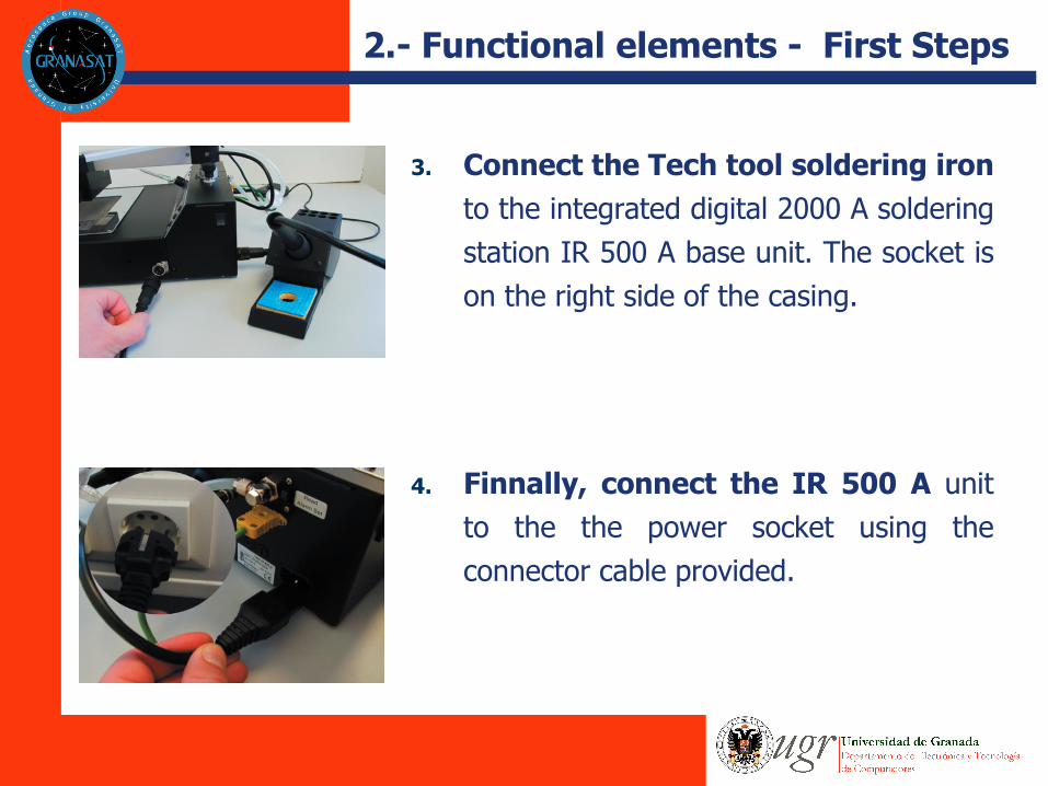
3. Connect the Tech tool soldering iron
to the integrated digital 2000 A soldering
station IR 500 A base unit. The socket is
on the right side of the casing.
4. Finnally, connect the IR 500 A unit
to the the power socket using the
connector cable provided.
3.- Desoldering
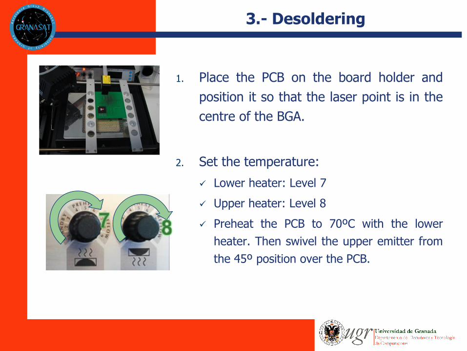
1. Place the PCB on the board holder and
position it so that the laser point is in the
centre of the BGA.
2. Set the temperature:
Lower heater: Level 7
Upper heater: Level 8
Preheat the PCB to 70ºC with the lower
heater. Then swivel the upper emitter from
the 45º position over the PCB.

3.- Desoldering
3. Once the melting point has been reached,
activate the vacuum (not too early)
pressing the finger switch
4. Spring force of the pipette. Now swivel
the upper emitter into the rear position.
This will automatically reduce the heat
energy in the upper heater.

3.- Desoldering
5. Activate the finger switch to switch off the
vacuum. The component will then drop
onto the storage tray.
6. Lower heater to 0
7. Cool the printed circuit board using the
fan.
4.- Soldering
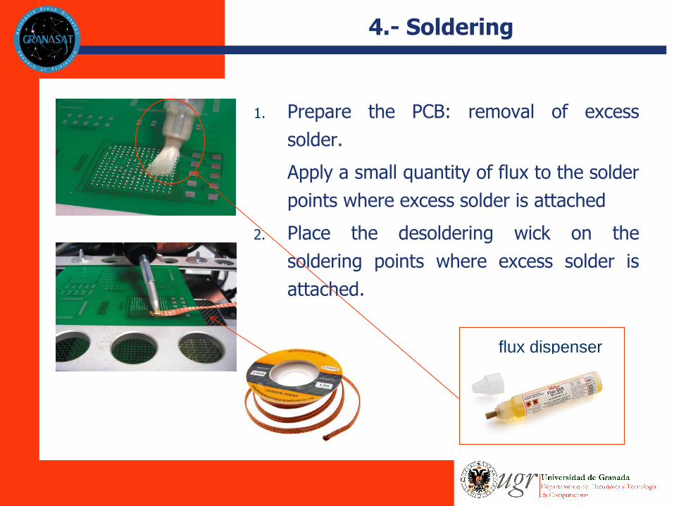
1. Prepare the PCB: removal of excess
solder.
Apply a small quantity of flux to the solder
points where excess solder is attached
2. Place the desoldering wick on the
soldering points where excess solder is
attached.
flux dispenser

4.- Soldering
3. Apply a flux cleaner or a lint free cloth (paño de microfibra sin pelusa) to remove residual flux from the soldering points.
4. To solder on a new BGA, apply flux(AGAIN) to the
soldering points again.
5. Place the component on the PCB. Fix the position
of the thermocouple so that its tip is in contact
with the PCB next to the BGA making sure that no
air gap is present. (lower temperature)
4.- Soldering
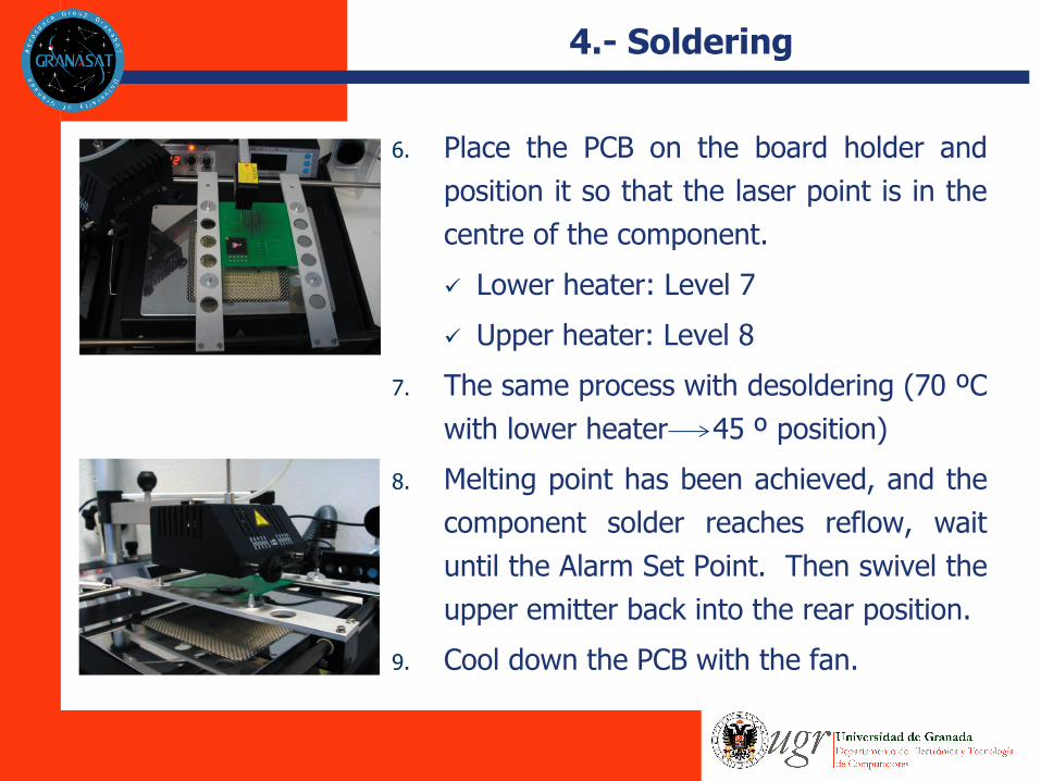
6. Place the PCB on the board holder and
position it so that the laser point is in the
centre of the component.
Lower heater: Level 7
Upper heater: Level 8
7. The same process with desoldering (70 ºC
with lower heater 45 º position)
8. Melting point has been achieved, and the
component solder reaches reflow, wait
until the Alarm Set Point. Then swivel the
upper emitter back into the rear position.
9. Cool down the PCB with the fan.

Appendix : Safety instructions

Example videos
https://www.youtube.com/watch?v=TobU9ugwY1g
https://www.youtube.com/watch?v=U55j58rIsyw
The best one: https://www.youtube.com/watch?v=q--U1axjD74
https://granasat.ugr.es/2017/07/27/soldering-facilities/
GranaSAT Soldering guides