error control and concealment for video communication: a
TRANSCRIPT
Error Control and Concealment forVideo Communication: A ReviewYAO WANG, MEMBER, IEEE, AND QIN-FAN ZHU, MEMBER, IEEE
The problem of error control and concealment in video com-munication is becoming increasingly important because of thegrowing interest in video delivery over unreliable channels suchas wireless networks and the Internet. This paper reviews the tech-niques that have been developed for error control and concealmentin the past 10–15 years. These techniques are described in threecategories according to the roles that the encoder and decoderplay in the underlying approaches. Forward error concealmentincludes methods that add redundancy at the source end to enhanceerror resilience of the coded bit streams. Error concealment bypostprocessing refers to operations at the decoder to recover thedamaged areas based on characteristics of image and video sig-nals. Last, interactive error concealment covers techniques that aredependent on a dialogue between the source and destination. Bothcurrent research activities and practice in international standardsare covered.
Keywords—Error concealment, error control in video transport,video communications.
I. INTRODUCTION
One inherent problem with any communications sys-tem is that information may be altered or lost duringtransmission due to channel noise. The effect of suchinformation loss can be devastating for the transport ofcompressed video because any damage to the compressedbit stream may lead to objectionable visual distortion at thedecoder. In addition, real-time/interactivity requirementsexclude the deployment of some well-known error-recoverytechniques for certain applications. Last, issues such asaudio-visual synchronization and multipoint communica-tions further complicate the problem of error recovery.
Transmission errors can be roughly classified into twocategories:random bit errorsand erasure errors. Randombit errors are caused by the imperfections of physicalchannels, which result in bit inversion, bit insertion, and bitdeletion. Depending on the coding methods and the affectedinformation content, the impact of random bit errors canrange from negligible to objectionable. When fixed-length
Manuscript received July 31, 1997; revised December 5, 1997. TheGuest Editor coordinating the review of this paper and approving it forpublication was T. Chen.
Y. Wang is with the Department of Electrical Engineering, PolytechnicUniversity, Brooklyn, NY 11201 USA.
Q.-F. Zhu is with PictureTel Corp., Andover, MA 01810 USA.Publisher Item Identifier S 0018-9219(98)03516-6.
coding is used, a random bit error will only affect onecode word, and the caused damage is generally acceptable.But if variable length coding (VLC) (for example, Huffmancoding) is used, random bit errors can desynchronize thecoded information such that many following bits are unde-codable until the next synchronization code word appears.In some cases, even after synchronization is obtained,decoded information can still be useless since there isno way to determine which spatial or temporal locationscorrespond to the decoded information. Erasure errors, onthe other hand, can be caused by packet loss in packetnetworks, burst errors in storage media due to physicaldefects, or system failures for a short time. Random biterrors in VLC can also cause effective erasure errorssince a single bit error can lead to many following bits’being undecodable and hence useless. The effect of erasureerrors (including those due to random bit errors) is muchmore destructive than random bit errors due to the loss ordamage of a contiguous segment of bits. Since almost allthe state-of-the-art video-compression techniques use VLCin one way or another, there is no need to treat randombit errors and erasure errors separately. The generic term“transmission errors” will be used throughout this paper torefer to both random bit errors and erasure errors.
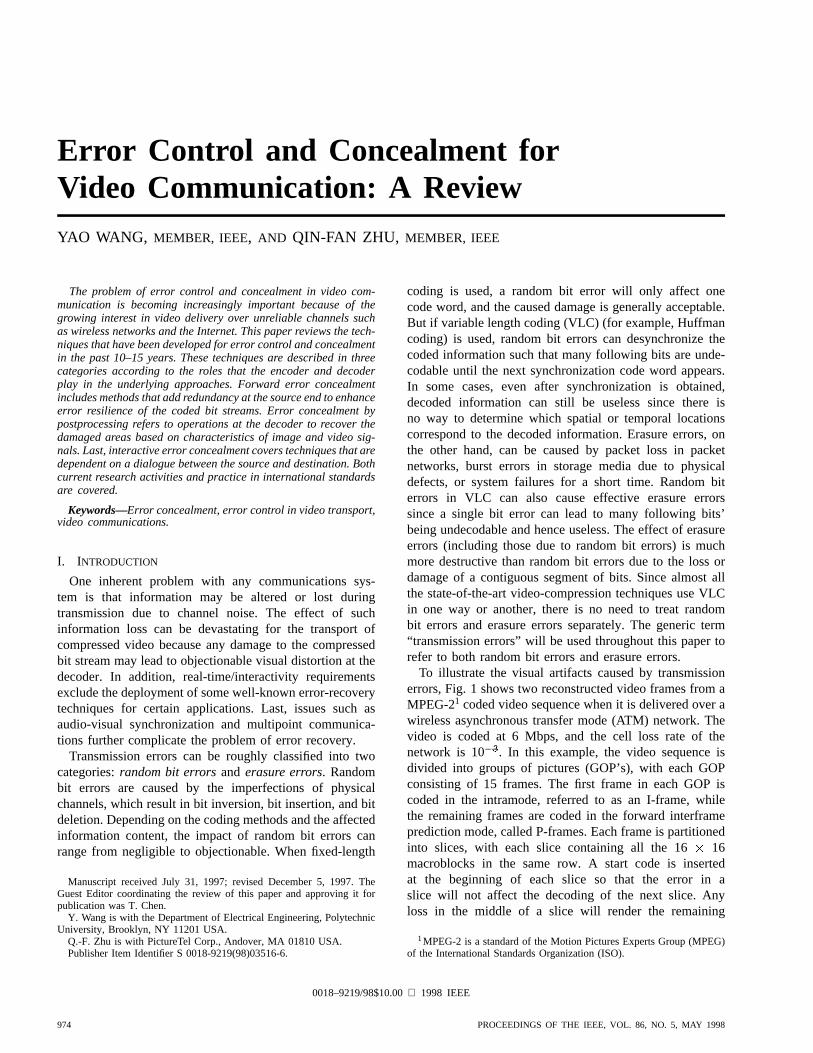
To illustrate the visual artifacts caused by transmissionerrors, Fig. 1 shows two reconstructed video frames from aMPEG-21 coded video sequence when it is delivered over awireless asynchronous transfer mode (ATM) network. Thevideo is coded at 6 Mbps, and the cell loss rate of thenetwork is 10 . In this example, the video sequence isdivided into groups of pictures (GOP’s), with each GOPconsisting of 15 frames. The first frame in each GOP iscoded in the intramode, referred to as an I-frame, whilethe remaining frames are coded in the forward interframeprediction mode, called P-frames. Each frame is partitionedinto slices, with each slice containing all the 16 16macroblocks in the same row. A start code is insertedat the beginning of each slice so that the error in aslice will not affect the decoding of the next slice. Anyloss in the middle of a slice will render the remaining
1MPEG-2 is a standard of the Motion Pictures Experts Group (MPEG)of the International Standards Organization (ISO).
0018–9219/98$10.00 1998 IEEE
974 PROCEEDINGS OF THE IEEE, VOL. 86, NO. 5, MAY 1998
(a)
(b)
Fig. 1. Two reconstructed frames from an MPEG-2 coded sequence when it is delivered over awireless ATM network. The video is coded at 6 Mbps. The cell-loss rate of the network is 10�3.All the macroblocks in a slice following a damaged macroblock are replaced by the correspondingmacroblocks in the previous frame. (a) Frame 15, an I-frame, which has three cell losses. The firsttwo cell losses occur in two consecutive slices in the upper part of the tree trunk. The third cell losshappens in the lower part of the tree trunk. (b) Frame 22, a P-frame, which has a single cell loss ata lower part of the tree, above the location of the third cell loss in Frame 15. One can observe theeffect of the cell loss of this frame as well as those propagated from Frame 15.
blocks in this slice undecodable. Furthermore, the damagedblocks in an I-frame will cause reconstruction errors in thefollowing P-frames. In this example, a damaged macroblockis simply replaced by the corresponding macroblock inthe reconstructed previous frame, which causes a visiblediscontinuity when the damaged block falls in a regionwith fast motion. The first image shown in Fig. 1 is an I-
frame, where three cell losses lead to three damaged slices.The second image is a P-frame, which has a single cellloss. Visible distortions appear in more than one slice,however, because of the error propagation effect. Whenthe reconstructed video is played back in real time, thesedistortions are visually annoying and are certainly notacceptable for entertainment applications.
WANG AND ZHU: ERROR CONTROL AND CONCEALMENT FOR VIDEO COMMUNICATION 975

Fig. 2. A functional block diagram for a video communicationssystem.
Techniques for combating transmission errors for videocommunication have been developed along two avenues.On one hand, traditional error control and recovery schemesfor data communications have been extended for videotransmission. These techniques aim at lossless recovery.Examples of such schemes include forward error cor-rection (FEC) or, more generally, error control coding(ECC), and automatic retransmission request (ARQ). Onthe other hand, signal-reconstruction and error-concealmenttechniques have been proposed that strive to obtain a closeapproximation of the original signal or attempt to make theoutput signal at the decoder least objectionable to humaneyes. Note that unlike data transmission, where losslessdelivery is required absolutely, human eyes can toleratea certain degree of distortion in image and video signals.In this paper, we attempt to summarize and critique theapproaches that have been developed for error control andconcealment in the past 10–15 years. The rest of this paperis organized as follows. Section II describes the variouscomponents involved in a visual communications systemand categorizes the approaches to the error control and con-cealment problem. Section III reviews techniques for errordetection. Sections IV–VI present the error-concealmentmethods in different categories. Last, Section VII drawssome concluding remarks.
II. PROBLEM FORMULATION AND
CATEGORIZATION OF APPROACHES
Fig. 2 shows a functional block diagram of a real-time video communications system. The input video iscompressed by the source encoder to the desired bit rate.The transport coderin the figure refers to an ensembleof devices performing channel coding, packetization and/ormodulation, and transport-level control using a particulartransport protocol. This transport coder is used to convertthe bit-stream output from the source coder into data unitssuitable for transmission. At the receiver side, the inverseoperations are performed to obtain the reconstructed videosignal for display. Note that although we only show a one-way transmission, we use double arrows to emphasize thefact that for some applications, there is a backward channelto convey information from the decoder to the encoder sidefor system control and error concealment.
Fig. 3. Illustration of the relationship between the quality ofreconstructed video at the decoder and the amount of concealmentredundancy employed under different channel error rates. The totalbandwidth used for source and channel coding is fixed.
The source codercan be further partitioned into twocomponents: thewaveform coderand theentropy coder.The waveform coder is a lossy device that reduces thebit rate by representing the original video using sometransformed variables and applying quantization. Examplesof waveform coders include transform coding using thediscrete cosine transform (DCT) and wavelet transforms,as well as vector quantization. The entropy coder, onthe other hand, is a lossless device that maps the outputsymbols from the waveform coder into binary code wordsaccording to the statistical distribution of the symbols to becoded. Examples of entropy-coding methods include Huff-man coding and arithmetic coding. Although the waveformcoder can use any known video-coding method, we willmainly focus on the type of hybrid coder that uses DCTand motion-compensated prediction. This coding schemehas been proven to be the most effective for a broadrange of applications and is the basis for all current video-coding standards [1]–[3]. The transport coder can varyfor different applications. Examples of real-time transportprotocols include H.221 in H.320, H.223 in H.324, andH.225 in H.323 [4]–[9].
In general, to help error detection and concealment atthe decoder, a certain amount of redundancy needs tobe added at the waveform-, entropy-, or transport-coderlevel. We refer to such added redundancy asconcealmentredundancy. Fig. 3 illustrates qualitatively the dependencyof the reconstructed video quality on the concealmentredundancy and channel error rate. Here, we assume thatthe total bit rate used for source and channel coding is fixed.The figure shows that as the channel error rate increases,a bigger percentage of the total bandwidth should beallocated for the concealment redundancy so as to achievethe best video quality. The error-concealment problemcan be formulated loosely as designing a pair of sourcecoder/decoder and transport coder/decoder so that the signaldistortion at the decoder is minimized with a given videosource model, total channel bandwidth, and channel errorcharacteristics.
976 PROCEEDINGS OF THE IEEE, VOL. 86, NO. 5, MAY 1998

The above problem is very difficult, if not impossible, tosolve due to the many involved variables and the fact thatit is often difficult to model or describe these variables.First, the design of a source coder requires a good modelof the source to improve its performance in terms of bothcoding efficiency and robustness to transmission errors.However, natural video sources are highly nonstationary innature, and no effective model has been found. In addition,error characteristics of some video transmission channelsare also nonstationary and can change significantly during aservice session. For example, an ATM network can becomecongested with the use of statistical multiplexing for a largenumber of sources, among other reasons. A mobile videophone may operate at dramatically different error ratesdepending on weather conditions, vehicle moving speeds,etc. Furthermore, other factors such as processing delay,implementation complexity, and application configurationfurther make the problem difficult to solve.
There have been many techniques proposed in the litera-ture that attack the transmission error problem from differ-ent angles. In most if not all cases, some of the variables arefixed first, and then a locally optimal solution is obtained.In this paper, we categorize these techniques into threegroups by whether the encoder or decoder plays the primaryrole or both are involved in cooperation.Forward errorconcealmentrefers to those techniques in which the encoderplays the primary role. In these techniques, the source-coding algorithm and/or transport-control mechanisms aredesigned either to minimize the effect of transmission errorswithout requiring any error concealment at the decoder orto make the error-concealment task at the decoder moreeffective. Examples of forward error concealment includeFEC, joint source and channel coding, and layered coding.On the other hand,error concealment by postprocessingincludes techniques in which the decoder fulfills the taskof error concealment. In general, these methods attempt torecover the lost information by estimation and interpolationwithout relying on additional information from the encoder.Spatial and temporal smoothing, interpolation, and filteringfall into this category. Last, if the encoder and decoderwork cooperatively to minimize the impact of transmissionerrors, the underlying techniques are calledinteractive errorconcealment. Examples in this category include ARQ andselective predictive coding based on feedback from thedecoder.
Before delving into the details of various techniques,it is worthwhile to mention the criteria for judging theirpros and cons. Obviously, the effectiveness of a techniquein terms of image quality is the most important. Therequired delay is also critical for two-way and multipointtransmission. The third factor is the bit-rate overhead in-curred by the added concealment redundancy at the sourceand/or transport level. Last, the processing complexity isalways an issue for any system. Note that the priority ofthese criteria may change depending on the underlyingapplication. For example, delay is much less importantfor one-way video transmission such as Internet videostreaming and video on demand than for two-way and
multipoint video conferencing. In addition, some of thetechniques can work for one specific application only, whileothers may be applied to or adapted to suit a broad rangeof applications. For instance, retransmission may workwell for point-to-point transmission, but it is difficult touse in multipoint applications. On the other hand, errorconcealment by decoder postprocessing can be applied inalmost any application.
III. ERROR DETECTION
Before any error-concealment technique can be appliedat the decoder, it is necessary first to find out whether andwhere a transmission error has occurred. In this section,we review some of the techniques developed for thispurpose. We divide these techniques into two categories:those performed at the transport coder/decoder and those atthe video decoder.
One way to perform error detection at the transportcoder is by adding header information. For example, inpacket-based video transmission, the output of the videoencoder is packetized into packets, each of which containsa header and payload field [10]. The header further con-tains a sequence number subfield that is consecutive forsequentially transmitted packets. At the transport decoder,the sequence number can be used for packet-loss detection.For example, the multiplex standard H.223 uses such amethod for packet-loss detection [6].
Another method for error detection at the transport levelis to use FEC [11]. In this method, error-correction en-coding is applied to segments of the output bit stream ofthe encoder. At the decoder, error-correction decoding isemployed to detect and possibly correct some bit errors.For example, H.223 uses FEC for both the multiplex packetheader and payload to detect errors in the header andpayload, respectively [6]. In H.261, an 18-bit FEC codeis applied to each video transport frame of 493 bits forerror detection and correction [1].
To accomplish error detection at the video decoder,characteristics of natural video signals have also beenexploited. In the methods proposed in [12] and [13], dif-ferences of pixel values between two neighboring linesare used for detecting transmission errors in pulse codemodulation (PCM) and differential (D)PCM coding. Whenthe difference is greater than a threshold, the current imagesegment is declared to be damaged. In [14], Mitchelland Tabatabai proposed to detect the damage to a singleDCT coefficient by examining the difference between theboundary pixels in a block and its four neighbor blocks.At the decoder, four separate difference vectors are formedby taking the differences between the current block andits adjacent blocks over the 1-pixel-thick boundary in fourdirections, respectively. Then a one-dimensional (1-D) DCTis applied to these difference vectors. Assuming that thetransition between blocks is smooth, the values of the 1-D DCT vectors should be relatively small in the absenceof transmission errors. Hence, if these vectors have a
WANG AND ZHU: ERROR CONTROL AND CONCEALMENT FOR VIDEO COMMUNICATION 977

dominant coefficient, then it is declared that one coefficient2
is damaged after some statistic test. In addition, the positionof the damaged coefficient is also estimated.
Lam and Reibman studied the problem of error detec-tion in the frequency domain [15]. With this approach, asynchronization code word is inserted at the end of eachscan line of blocks. When a synchronization code word iscaptured at the end of a scan line, the number of blocksdecoded is checked against a predetermined number. Ifa difference is found, then an error is declared and theposition of the erroneous block is determined as follows.A weighted mean squared error is calculated between thecoefficients of each block in the current line and that inthe previous line for an 8 8 block. A larger weight isused for low-frequency coefficients and a smaller weightfor high-frequency coefficients, so that the distortion mea-sure correlates more closely to the human visual system.The block with the maximum error is recognized as theerroneous block. This block is split into two blocks ormerged with an adjacent block, depending on whether thenumber of blocks decoded is smaller or larger than theprescribed number. When multiple blocks are damaged, theabove detection and splitting/merge procedure repeats untilthe number of blocks matches the desired one.
As mentioned previously, when VLC is used in the sourcecoder, any damage to a single bit can cause desynchroniza-tion, resulting in the subsequent bits’ being undecodable.However, this property can be used as a means to detecttransmission errors. Note that in most cases, the VLC beingused is not a complete code, i.e., not all the possible codewords are legitimate code words. Hence, once a videodecoder detects a code word that is not in its decoding table,a transmission error is declared. In addition, the syntaxembedded in the bit stream can also be used for errordetection. For example, if the decoded quantization step sizeis zero, or the number of decoded DCT coefficients is morethan the maximum number of coefficients (for example, 64for an 8 8 DCT transform coder), then a transmissionerror is detected.
Generally, error detection by adding header informationand/or FEC codes at the transport level is more reliable,albeit at the expense of additional channel bandwidth. Thebenefit of error-detection techniques at the video decoderthat rely on the smoothness property of video signals isthat they do not add any bits beyond that allocated to thesource coder. The use of synchronization code words and/orincomplete VLC codes offers a compromise: by retaininga small degree of redundancy in the encoding process, iteases the error detection at the decoder. Obviously, thesetechniques are not mutually exclusive and can be employedjointly in practical systems.
IV. FORWARD ERROR CONCEALMENT
In the previous section, we reviewed techniques fordetecting transmission errors. From this section onwards,
2This scheme assumes that at most, one coefficient is damaged. In theevent that multiple coefficients are damaged, the algorithm detects andcorrects only the coefficient that has the largest error.
we will assume that the locations of errors are knownand discuss techniques for concealing the detected errors.In this section, we describe error-concealment techniquesin which the encoder plays the primary role. When thetransport channel is not lossless, there are two kinds ofdistortion observed at the decoder. The first is the quanti-zation noise introduced by the waveform coder. The secondis the distortion due to transmission errors. An optimalpair of source coder and transport coder (including FEC,packetization, and transport protocols) should be designedsuch that the combined distortion due to both quantizationand transmission errors is minimized, given the availablebandwidth and channel error characteristics. Typically, thevideo codec is designed to minimize the quantization errorgiven the available bandwidth. This practice is guided bythe well-known source-channel separation theorem of Shan-non, which states that one can separately design the sourceand channel coder to achieve the optimal performance of theoverall system. This result was first shown by Shannon forsource and channels that are memoryless and stationary [16]and was later extended to a more general class of sourcesand channels [17]. However, this theorem assumes that thecomplexity and processing delay of the source and channelcoder can be infinite. In most real-world applications, theabove assumptions are not true. First, both the sourcesignals and channel environments can vary rapidly andhence are nonstationary. Second, source and channel codershave to be implementable with acceptable complexity anddelay. In this situation, joint design of source and channelcoder (more generally, transport coder) may achieve betterperformance.
There are many ways to accomplish forward error con-cealment. Essentially, they all add a controlled amountof redundancy in either the source coder or the transportcoder. In the first case, the redundancy can be added ineither the waveform coder or the entropy coder. Some tech-niques require cooperation between the source and transportcoders, while others merely leave some redundancy in oradd auxiliary information to the coded data that will helperror concealment at the decoder. Some techniques requirethe network to implement different levels of quality ofservice (QoS) control for different substreams, while othersassume parallel equal paths. In the following, we reviewthese approaches separately.
A. Layered Coding with Transport Prioritization
Until now, the most popular and effective scheme forproviding error resilience in a video transport system hasbeen layered coding combined with transport prioritization.3
In layered coding, video information is partitioned intomore than one group or layer [3], [18]–[24]. Fig. 4 showsthe block diagram of a generic two-layer coding andtransport system. The base layer contains the essentialinformation for the video source and can be used to generate
3The term transport prioritization here refers to various mechanismsto provide different QoS in transport, including using unequal errorprotection, which provides different channel error/loss rate, and assigningdifferent priorities to support different delay/loss requirements.
978 PROCEEDINGS OF THE IEEE, VOL. 86, NO. 5, MAY 1998

Fig. 4. Block diagram of a system using layered coding and prioritized transport.
an output video signal with an acceptable quality. Withthe enhancement layers, a higher quality video signal canbe obtained. To combat channel errors, layered codingmust be combined with transport prioritization so thatthe base layer is delivered with a higher degree of errorprotection. Different networks may implement transportprioritization using different means. In ATM networks,there is one bit in the ATM cell header that signals itspriority. When traffic congestion occurs, a network nodecan choose to discard the cells having low priority first.Transport prioritization can also be implemented by usingdifferent levels of power to transmit the substreams in awireless transmission environment. This combination oflayered coding with unequal power control has been studiedfor video transmission in wireless networks [22], [23]. Inaddition, prioritization can be realized with using differenterror-control treatments to various layers. For example,retransmission and/or FEC can be applied for the base layer,while no or weaker retransmission/FEC may be applied tothe enhancement layers. This approach was taken in thewireless video transport system proposed in [23].
Layered coding can be implemented in several differentfashions depending on the way the video information ispartitioned. When the partition is performed in the temporaldomain, the base layer contains a bit stream with a lowerframe rate, and the enhancement layers contain incrementalinformation to obtain an output with higher frame rates.In spatial domain layered coding, the base layer codesthe subsampled version of the original video sequenceand the enhancement layers contain additional informationfor obtaining higher spatial resolution at the decoder. Thebase layer can also encode the input signal with a coarserquantizer, leaving the fine details to be specified in theenhancement layers. In general, it can be applied to theinput samples directly or the transformed samples. We referthe first two techniques astemporaland spatial resolutionrefinement,respectively, and the third one asamplituderesolution refinement. Last, in transform or subband basedcoders, one can include the low-frequency coefficients orlow-frequency band subsignals in the base layer whileleaving the high-frequency signal in the enhancement layer.We call this techniquefrequency-domain partitioning. In avideo coder using motion-compensated prediction, the cod-ing mode and motion vectors are usually put into the baselayer since they are the most important information. Note
that the above schemes do not have to be deployed in isola-tion; rather, they can be used in different combinations. TheMPEG-2 video-coding standard provides specific syntax forachieving each of the above generic methods. In MPEG-2terminology, layered coding is referred to as scalability, andthe above four types of techniques are known astemporalscalability, spatial scalability, signal-to-noise-ratio (SNR)scalability, and data partitioning,respectively [3].
Although no explicit overhead information is added inlayered coding, the graceful degradation of the imagequality in the presence of transmission errors is obtained bytrading off the compression gain and system complexity.In general, both the encoder and the decoder have to beimplemented with the more complicated multilayer struc-ture. In addition, layering will add more coding overheadin the source coder and the transport layer. The codingoverhead depends on several factors, including the layeredcoding method, source spatial and temporal resolution,and bit rate. For example, with the data partition method,a relatively lower overhead will be needed at a higherbit rate than that at a lower bit rate. The four methodspresented above have different tradeoffs between robustnessto channel noise and coding gain. The study in [24]has found that the three scalability modes in MPEG-2—namely, data partitioning, SNR scalability, and spatialscalability—have increasingly better error robustness, inthat order, but also increasing coding overhead. To be moreprecise, data partitioning requires the least number of bits(requiring only 1% more bits than a single-layer coder atthe bit rate of 6 Mbps) to achieve the same image qualitywhen both layers are error free, while the spatial scalabilityhas a better reconstructed image when there exist significantlosses in the enhancement layer. SNR scalability is in themiddle on both scales. Compared to the one-layer coder,the coder performance is improved significantly over theone-layer coder in presence of channel errors at a relativelysmall amount of overhead. Table 1 summarizes the requiredratio of the base layer to the total bit rate and the highestpacket loss rate at which the video quality is still consideredvisually acceptable. These results are obtained by assumingthat the base layer is always intact during the transmission.
When designing a layered coder, a factor that needs tobe taken into account is whether the information fromthe enhancement layers will be used for the predictionin the base-layer coding. When it is used, the coding
WANG AND ZHU: ERROR CONTROL AND CONCEALMENT FOR VIDEO COMMUNICATION 979

Table 1 Comparison of Different Scalability Modes in the MPEG-2 Video Coder(Summarized from Experimental Results Reported in [24])
gain in the base layer will be improved. But when theenhancement information is lost during transmission, it willcause distortion in the base layer in addition to the distortionin the enhancement layer. Hence, in some systems, the base-layer prediction is performed with information from thebase layer only in order to prevent this prediction memorymismatch in the base layer [18].
B. Multiple-Description Coding
As described in Section IV-A, layered coding can offererror resilience when the base layer is transmitted in anessentially error-free channel, realized via strong FEC andretransmission. In certain applications, however, it maynot be feasible or cost effective to guarantee losslesstransmission of a certain portion of the transmitted data.In this case, a loss in the base layer can lead to a disastrouseffect in the decoded visual quality. An alternative approachto combat transmission errors from the source side isby usingmultiple-description coding(MDC). This codingscheme assumes that there are several parallel channelsbetween the source and destination and that each channelmay be temporarily down or suffering from long bursterrors. Furthermore, the error events of different channelsare independent, so that the probability that all channelssimultaneously experience losses is small. These channelscould be physically distinct paths between the source anddestination in, for example, a wireless multihop networkor a packet-switched network. Even when only one singlephysical path exists between the source and destination, thepath can be divided into several virtual channels by usingtime interleaving, frequency division, etc.
With MDC, several coded bit streams (referred to as“descriptions”) of the same source signal are generatedand transmitted over separate channels. At the destination,depending on which descriptions are received correctly,different reconstruction schemes (or decoders) will be in-voked. The MDC coder and decoder are designed such thatthe quality of the reconstructed signal is acceptable withany one description and that incremental improvement isachievable with more descriptions. A conceptual schematicfor a two-description coder is shown in Fig. 5. In this case,there are three decoders at the destination, and only oneoperates at a time. To guarantee an acceptable quality witha single description, each description must carry sufficientinformation about the original signal. This implies that therewill be overlap in the information contained in differentdescriptions. Obviously, this will reduce the coding ef-
Fig. 5. Illustration of multiple description coding and decoding.
ficiency compared to the conventional single descriptioncoder (SDC) that is aimed at minimizing the distortion inthe absence of channel loss. This has been shown usinga rate-distortion analysis for different types of sources[25]–[27]. However, this reduced coding efficiency is inexchange for increased robustness to long burst errorsand/or channel failures. With SDC, one would have tospend many error-control bits and/or introduce additionallatency (in all the bits or only the base layer in the layeredcoding case) to correct such channel errors. With MDC, along burst error or even the loss of an entire descriptiondoes not have a catastrophic effect as long as not all thesubstreams experience failure simultaneously. Thus, onecould use fewer error-control bits for each substream.
A simple way of obtaining multiple equally importantdescriptions is by splitting adjacent samples among severalchannels using an interleaving subsampling lattice and thencoding the resulting subimages independently [28]–[31]. Ifone subimage is lost, it can be recovered satisfactorily basedon correlation among adjacent samples in the original im-age. This approach requires a quite large bit-rate overheadbecause the coder cannot make use of the correlation amongadjacent samples. In the following, we review two otherapproaches that are more efficient.
1) Multiple-Description Scalar Quantization (MDSQ):Inthe approach of Vaishampayan [30], two substreams areobtained by producing two indexes for each quantized level.The index assignment is designed so that if both indexesare received, the reconstruction accuracy is equivalent toa fine quantizer. On the other hand, if only one index isreceived, the reconstruction accuracy is essentially that of a
980 PROCEEDINGS OF THE IEEE, VOL. 86, NO. 5, MAY 1998

coarse quantizer. A simple implementation of this approachis by using two quantizers whose decision regions shift byhalf of the quantizer interval with respect to each other(known as A2 index assignment [30]). If each quantizerhas a bit rate of , the reconstruction error from twodescriptions (i.e., both indexes for each quantized sample)is equivalent to that of a single bit quantizer. Onthe other hand, if only one description is available, theperformance is equivalent to that of a singlebit quantizer.In the absence of channel failure, a total of bits arerequired to match the performance of a single quantizerwith bits. Therefore, the loss of coding efficiencyis quite significant for large values of . At lower bitrates, the overhead is smaller. More sophisticated quantizermappings can be designed to improve the coding efficiency.The MDSQ approach is first analyzed assuming both indexstreams are coded using fixed-length coding [30]. It is laterextended to consider entropy coding of the indexes [31].The original MDSQ approach is developed for memorylesssources. To handle sources with memory, MDSQ can beembedded in a transform coder by coding each transformcoefficient using MDSQ [32], [33]. This approach has beenapplied to transform-based image and video coders.
2) MDC Using Correlation-Inducing Linear Transforms:Another way of introducing correlation between multiplestreams is by linear transforms that do not completelydecorrelate the resulting coefficients. Ideally, the trans-form should be such that the transform coefficients canbe divided into multiple groups so that the coefficientsbetween different groups are correlated. This way, if somecoefficient groups are lost during transmission, they can beestimated from the received groups. To minimize the lossof coding efficiency, the coefficients within the same groupshould be uncorrelated. To simplify the design process fora source signal with memory, one can assume the presenceof a prewhitening transform so that the correlation-inducingtransform can operate on uncorrelated samples.
In [34] and [35], Wanget al. and Orchardet al., respec-tively, proposed applying a pair-wise correlating transform(PCT) to each pair of uncorrelated variables obtained fromthe Karhunen-Loeve transform (KLT). The two coefficientsresulting from the PCT are split into two streams that arethen coded independently. If both streams are received, thenan inverse PCT is applied to each pair of transformed coef-ficients, and the original variables can be recovered exactly(in the absence of quantization errors). If only one streamis received, the missing stream can be estimated based onthe correlation between the two streams. In [34], the PCTuses a 45 rotation matrix, which yields two coefficientshaving equal variance and therefore requiring the samenumber of bits. More general classes of PCT using anyrotation matrix (i.e., orthogonal) as well as nonorthogonalmatrices are considered in [35]. The overhead introducedby this approach can be controlled by the number ofcoefficients that are paired, the pairing scheme, and thetransform parameters (e.g., the rotation angle). This method
has been integrated in a JPEG4-like coder, in which the PCTis applied to the DCT (similar to KLT in decorrelationcapability) coefficients. Only the 45rotation case hasbeen simulated. It is shown that to guarantee a satisfactoryquality from one stream, about 20% overhead is requiredover the JPEG coder for 512 512 images coded at about0.6 bits per pixel (bpp). As noted before for layered coding,the overhead rate depends on the type of image being codedand the reference bit rate.
Instead of designing the transform basis functions tointroduce correlation among coefficients in the same block,an alternative approach is to introduce correlation amongthe same coefficients in different blocks. Then one canobtain multiple descriptions by splitting coefficients inadjacent blocks into separate descriptions and recover lostcoefficient blocks in one description from the coefficientblocks in the other description by making use of theinterblock correlation. To introduce additional correlationbeyond what is originally present between adjacent imageblocks, overlapping block transforms can be used. In [36],Hemami designed a family of lapped orthogonal transform(LOT) bases, referred to as T6–T9, which achieve differ-ent tradeoffs between compression gain and reconstructiongain. The latter is defined for a special case in which a lostblock is recovered by the mean of four adjacent blocks.Recently, Chung and Wang [37] developed a reconstructionmethod that can achieve significantly better reconstructionquality than the mean reconstruction method. The methodis based on the principle of maximally smooth recovery, tobe introduced in Section V-B. It was found that with theT6 basis, satisfactory image quality can be guaranteed froma single description alone (including every other block) ata bit rate overhead of 0.3–0.4 bpp over that achievable bythe LOT-DCT basis, which is designed to maximize thecoding efficiency [38]. Interestingly, their study found thatthe required number of additional bits is fairly constantamong different images, so that the relative overhead islower for an image requiring a high bit rate. For the image“Lena,” the relative overhead is about 30–40%, while forthe more complex image “People,” which is a snapshot ofa crowded audience, it is merely 10%.
Given the relatively large overhead associated with MDC,this approach is appropriate only for channels that haverelatively high loss or failure rates. When the channel lossrate is small, the reconstruction performance in the error-free case dominates, and the SDC, which is optimized forthis scenario, performs best. On the other hand, when theloss rate is very high, the reconstruction quality in thepresence of loss is more critical, so that the MDC approachbecomes more suitable. For example, it has been foundthat under the same total bit rate, the reconstruction qualityobtained with the transform coder using PCT exceeds thatof the JPEG coder (with even and odd blocks split amongtwo channels) only when the block loss rate is larger than10 [39]. Similarly, in the MDC coder using LOT, theT6–T9 bases were shown to provide better reconstruction
4JPEG is a standard of the Joint Photographic Experts Group of theISO.
WANG AND ZHU: ERROR CONTROL AND CONCEALMENT FOR VIDEO COMMUNICATION 981

quality than the DCT-LOT basis only when the block lossprobability is larger than 0.025 [37]. A challenging task ishow to design the MDC coder that can automatically adaptthe amount of added redundancy according to underlyingchannel error characteristics.
C. Joint Source and Channel Coding
In layered coding and MDC, introduced previously, theinteraction between the source and channel coders is exer-cised at a high level. In layered coding, the source coderproduces a layered stream assuming that the channel codercan guarantee the delivery of the most important sourcelayer. On the other hand, with MDC, the source coderassumes that all coded bits will be treated equally and thatall are subject to loss. In this section, we review techniquesthat invoke the source-channel interaction at a lower level,i.e., the quantizer and entropy-coder design at the sourcecoder and the design of FEC and modulation schemes atthe channel coder. This type of approach is traditionallyreferred to asjoint source and channel coding,althoughin a broader sense, layered coding and MDC can also beconsidered to belong to this category.
In general, joint source and channel coding is accom-plished by designing the quantizer and entropy coder forgiven channel error characteristics to minimize the effectof transmission errors. Spilker noted that when the channelbecomes very noisy, a coarse quantizer in the source-coding stage outperforms a fine quantizer for a PCM-basedsource coder [40]. Kurtenbach and Wintz designed optimalquantizers to minimize the combined mean square errorintroduced by both quantization and channel errors giventhe input data probability distribution and the channel errormatrix [41]. Farvardin and Vaishampayan further extendedthe design of the optimal quantizer and also proposed amethod for performing the code-word assignment to matchthe channel error characteristics [42].
The above studies were conducted for a general source.For image signals, Modestino and Daut first considered theapplication of convolution codes to protect against channelerrors following a source coder using DPCM [43]. Thistechnique was later extended to transform coders usingDCT [44]. Three options were proposed to implementcombined source and channel coding. In the first option,modulation and ECC are the same for all the bits inevery quantized transform coefficient. In the second option,modulation and ECC are the same for all the bits belongingto the same quantized coefficient but can be different fordifferent coefficients. In the third option, modulation andFEC are allowed to vary among different bits of the samecoefficient. It was shown that with the first option, for atypical outdoor image, when the channel SNR is smallerthan 10 dB, the SNR for the received picture is better with50% error-correction bits than without any error correctionbits. The second and third options can further extend thechannel SNR threshold to below 5 dB [44]. Vaishampayanand Farvardin considered the adaptation of bit allocation(assuming fixed-length coding) for DCT coefficients basedon channel error characteristics [45]. The basic conclusion
was that for noisier channels, fewer bits should be allocatedto the high-frequency coefficients and more bits should beallocated to the low-frequency coefficients.
D. Robust Waveform Coding
In traditional source-coder design, the goal is to eliminateboth the statistical and the visual redundancy of the sourcesignal as much as possible to achieve the best compressiongain. This, however, makes the error-concealment task atthe decoder very difficult. One approach to solve thisproblem is by intentionally keeping some redundancy inthe source-coding stage such that better error concealmentcan be performed at the decoder when transmission errorsoccur. We refer to techniques in this group asrobustwaveform coding. Strictly speaking, layered coding andMDC both belong to this category, as they both addsome redundancy in the coded bit streams to provide therobustness to channel errors. The techniques described inthis subsection assume that the coded source signal willbe transmitted in a single channel. They can be applied toproduce individual streams in layered coding and MDC.
1) Adding Auxiliary Information in the Waveform Coder:One simple approach to combat transmission errors is byadding auxiliary information in the waveform coder thatcan help signal reconstruction in the decoder. As will beshown in Section V-A, an effective technique for error con-cealment in the decoder is the use of motion-compensatedtemporal interpolation. This requires knowledge of themotion vectors of the lost blocks. One way to help the error-concealment task is by sending motion vectors for mac-roblocks that would not ordinarily use motion-compensatedprediction. For example, in MPEG-2, the coder has theoption of sending motion vectors for macroblocks in I-frames, so that I-frames can be recovered reliably [3]. Inthe absence of channel errors, these motion vectors areuseless. However, when certain macroblocks in an I-frameare damaged, their motion vectors can be estimated fromthose of the surrounding received macroblocks, and thenthese macroblocks can be recovered from the correspondingmotion-compensated macroblocks in the previous frame.
In [46], Hemami and Gray proposed to add some auxil-iary information in the compressed bit stream so that thedecoder can interpolate lost image blocks more accurately.A damaged image block is interpolated at the decoder usinga weighted sum of its correctly received neighbor blocks.Determination of the interpolation coefficients is combinedwith vector quantization in a single step at the encoder, andthe resulting quantized weights are transmitted as overheadinformation, which is less than 10% for typical JPEG-codedimages.
2) Restricting Prediction Domain:To reduce the effectof error propagation due to the use of prediction, onecan limit the prediction within nonoverlapping spatial andtemporal regions. For example, the H.263 standard divides apicture intoslices,and in theindependent segment decodingmode, spatial and temporal prediction is confined withineach slice. Here, spatial prediction refers to prediction ofDCT coefficients and motion vectors of one macroblock
982 PROCEEDINGS OF THE IEEE, VOL. 86, NO. 5, MAY 1998

from adjacent macroblocks, and temporal prediction is thewell-known motion-compensated interframe prediction. Tofurther suppress the effect of temporal error propagation,in the H.263 standard, input video frames are partitionedinto separate groups calledthreads, and each thread iscoded without using other threads for prediction [47]. Thisis referred to asvideo redundancy coding. For example,when two threads are used, the even and odd frames aregrouped separately, and temporal prediction is performedwithin each group. All the threads start from the same sync-frame (for example, I-frame) and end at another sync-frame.When a transmission error occurs in one frame, only onethread will be affected. Between the affected frame and thenext sync-frame, a video signal with half the frame rate canbe produced. Obviously, restricting the prediction domainas described above will reduce the coding efficiency. But itwill also confine the picture-quality degradation to only oneregion when a transmission error occurs. Therefore, this isanother way to trade off coding gain for better reconstructedpicture quality.
E. Robust Entropy Coding
In the techniques described in Section IV-D, redundan-cies are added during the waveform coding stage. Onecan also add redundancy in the entropy-coding stage tohelp detect bit errors and/or prevent error propagation. Wecall such techniquesrobust entropy coding. In this section,we first review techniques that use synchronization codewords to limit error propagation in compressed data andthen describe several VLC codes that are designed to beerror resilient.
1) Self-Synchronizing Entropy Coding:When VLC isused in video coding, a single bit error can lead to theloss of synchronization. First, the decoder may not knowthat a bit error has happened. Furthermore, even whenthe decoder recognizes that an error has occurred byother means such as the underlying transport protocol,it may not know which bit is in error and hence it cannotdecode the subsequent bits. One way to prevent this is todesignate one code word as the synchronization code wordin the entropy coder [48]–[52]. A synchronization codeword has the property that the entropy decoder will regainsynchronization once a decoder captures such a code word.Generally, the resulting entropy coder will be less efficientin terms of the compression ratio than the “optimal” coderwithout using the synchronization code word.
Although synchronization can be obtained with a syn-chronization code word, the number of decoded symbolsmay be incorrect. This will typically result in a shift ofsequential blocks in a block-based coder. To solve thisproblem, a distinct synchronization code word can beinserted at a fixed interval either in the pixel domain [51],[52] or in the bit-stream domain where the number ofcoded bits is used for measuring the interval [53], [54].Side information such as spatial and temporal locations isnormally included after the synchronization code word toidentify where the decoded blocks belong. The synchroniza-tion code word in this case does not carry any information
on the encoded video but only plays the role of enablingthe decoder to regain synchronization. Several methodshave been proposed to minimize the bit-rate overheadintroduced by the synchronization code word [51], [52].While a shorter synchronization code word introduces lessoverhead, it also increases the probability that a bit errormay generate a fake synchronization code word. Hence, inpractical video-coding systems such as H.261 and H.263,relatively long synchronization code words are used instead[1], [2].
For high-error-rate environments such as wireless net-works, MPEG-4 allows the insertion of an additional syn-chronization code word, known asmotion marker,withineach coded block between the motion information andthe texture information [53], [54]. When only the textureinformation is damaged, then the motion information for ablock can be still used for better error concealment withtechniques to be described in Section V.
2) Error-Resilient Entropy Coding (EREC):With the meth-ods described above, error propagation is limited to themaximum separation between the synchronization codewords. To reduce the introduced redundancy, however,these codes have to be used infrequently. Kingsburyet al.have developed EREC methods [55], [56]. In the method of[56], variable-length bit streams from individual blocks aredistributed into slots of equal size. Initially, the coded datafor each image block are placed into the designated slot forthe block either fully or partially. Then, a predefined offsetsequence is used to search for empty slots to place anyremaining bits of blocks that are bigger than the slot size.This is done until all the bits are packed into one of the slots.With EREC, the decoder can regain synchronization at thestart of each block. It also ensures that the beginning of eachblock is more immune to error propagation than those atthe end. This way, error propagation is predominant only inhigher frequency coefficients. The redundancy introducedby using EREC is negligible. In [56], when EREC isintegrated into an H.261 like coder, the reconstructionquality at the bit error rate (BER) of 10–10 is sig-nificantly better. Recently, the above EREC method hasbeen used to transcode an MPEG-2 bit stream to makeit more error resilient [57]. With additional enhancementand error concealment, the video quality at a BER of10 was considered acceptable. Kawahara and Adachi alsoapplied the EREC method at the macroblock level togetherwith unequal error protection for H.263 transmission overwireless networks [58]. Their simulation results show thatthe proposed method outperforms the plain FEC both forrandom bit errors at BER greater than 10and for bursterrors.
In the error-resilient mode of MPEG-4 [53], [54], re-versible variable-length code (RVLC) is employed, whichcan make full use of the available data when a transmissionerror occurs. RVLC is designed in such a way that once asynchronization code word is found, the coded bit streamcan be decoded backward. With conventional VLC, all dataafter an erroneous bit are lost until the next synchronizationcode word. On the other hand, RVLC can recover data
WANG AND ZHU: ERROR CONTROL AND CONCEALMENT FOR VIDEO COMMUNICATION 983

Fig. 6. Illustration of FEC with interleaving for ATM cell-lossrecovery. The numbers in the figure are in bytes.
backward from the next synchronization code word detecteduntil the first decodable code word after the erroneous bit.This improved robustness is again achieved at a reducedcoding efficiency, which is due to the constraint imposedby constructing the RVLC tables.
F. FEC Coding
FEC is well known for both error detection and errorcorrection in data communications. FEC has the effect ofincreasing transmission overhead and hence reducing usablebandwidth for the payload data. Therefore, it must be usedjudiciously in video services that are very demanding inbandwidth but can tolerate a certain degree of loss. FEC hasbeen studied for error recovery in video communications[59]–[64]. In H.261, an 18-bit error-correction code iscomputed and appended to 493 video bits for detection andcorrection of random bit errors in integrated services digitalnetwork (ISDN). For packet video, it is much more difficultto apply error correction because several hundred bits haveto be recovered when a packet loss occurs.
In [59], Lee et al. proposed to combine Reed–Solomon(RS) codes with block interleaving to recover lost ATMcells. As shown in Fig. 6, an RS (32,28,5) code is appliedto every block of 28 bytes of data to form a block of32 bytes. After applying the RS code row by row in thememory up to the forty-seventh row, the payload of 32ATM cells is formed by reading column by column fromthe memory with the attachment of one byte indicating thesequence number. In this way, a detected cell loss at thedecoder corresponds to one byte erasure in each row of 32bytes after deinterleaving. Up to four lost cells out of 32cells can be recovered. The Grand-Alliance high-definitiontelevision broadcast system has adopted a similar techniquefor combating transmission errors [60]. In addition to usingthe RS code, data randomization and interleaving are alsoemployed for additional protection.
Because a fixed amount of video data has to be ac-cumulated to perform the block interleaving describedabove, relatively long delay will be introduced. To reducethe interleaving delay, a diagonal interleaving method isproposed in [63]. At the encoder side, input data are storedhorizontally in a designated memory section, which are thenread out diagonally to form ATM cells. In the decoder, thedata are stored diagonally in the memory and are read out
horizontally. In this way, the delay due to interleaving ishalved.
The use of FEC for MPEG-2 in a wireless ATM local-area network has been studied by Ayanogluet al. in [64].FEC is used at the byte level for random bit error correctionand at the ATM cell level for cell-loss recovery. TheseFEC techniques are applied to both single-layer and two-layer MPEG data. It was shown that the two-layer coderoutperforms the one-layer approach significantly, at a fairlysmall overhead. The paper also compared direct cell-levelcoding with the cell-level interleaving followed by FEC. Itis interesting to note that the paper concludes that the latterintroduces longer delay and bigger overhead for equivalenterror-recovery performance and suggests that direct cell-level correction is preferred.
G. Transport-Level Control
The forward error concealment techniques reviewedabove are exercised at the source coder. Forward errorconcealment can also be accomplished at the transportlevel. A good example of this is error isolation by structuredpacketization schemes in packet video. The output of thesource coder is assembled into transport packets in such away that when a packet is lost, the other packets can stillbe useful because the header and coding mode informationis embedded into successive packets [65], [66].
A packet often contains data from several blocks. Toprevent the loss of contiguous blocks because of a singlepacket loss, interleaved packetization can be used, by whichsuccessive blocks are put into nonadjacent packets [19],[61]. This way, a packet loss will affect blocks in aninterleaved order (i.e., a damaged block is surrounded byundamaged blocks), which will ease the error-concealmenttask at the decoder. Note that the use of interleaved pack-etization in the transport layer requires the source coder toperform block-level prediction only within blocks that are tobe packetized sequentially. This will reduce the predictiongain slightly.
Last, the binary bits in a compressed video bit streamare not equally important. When layered coding is usedat the source coder, the transport controller must assignappropriate priority to different layers, which is a form oftransport-level control. Even with a nonlayered coder, thepicture header and other side information are much moreimportant than the block data. These important bits shouldbe protected so that they can be delivered with a muchlower error rate. One way to realize this is by using dualtransmission of important information. In [67], dual trans-mission for picture header information and quantizationmatrix was proposed for MPEG video. In [68], Civanlarand Cash considered video-on-demand services over anATM network where the servers and the clients are Internetprotocol based and are connected to the network via a fiberdistributed data interface network. They proposed to usetransmission control protocol (TCP) for transmission of avery small amount of high-priority data before a servicesession and user datagram protocol for the remaining low-priority data during the session.
984 PROCEEDINGS OF THE IEEE, VOL. 86, NO. 5, MAY 1998
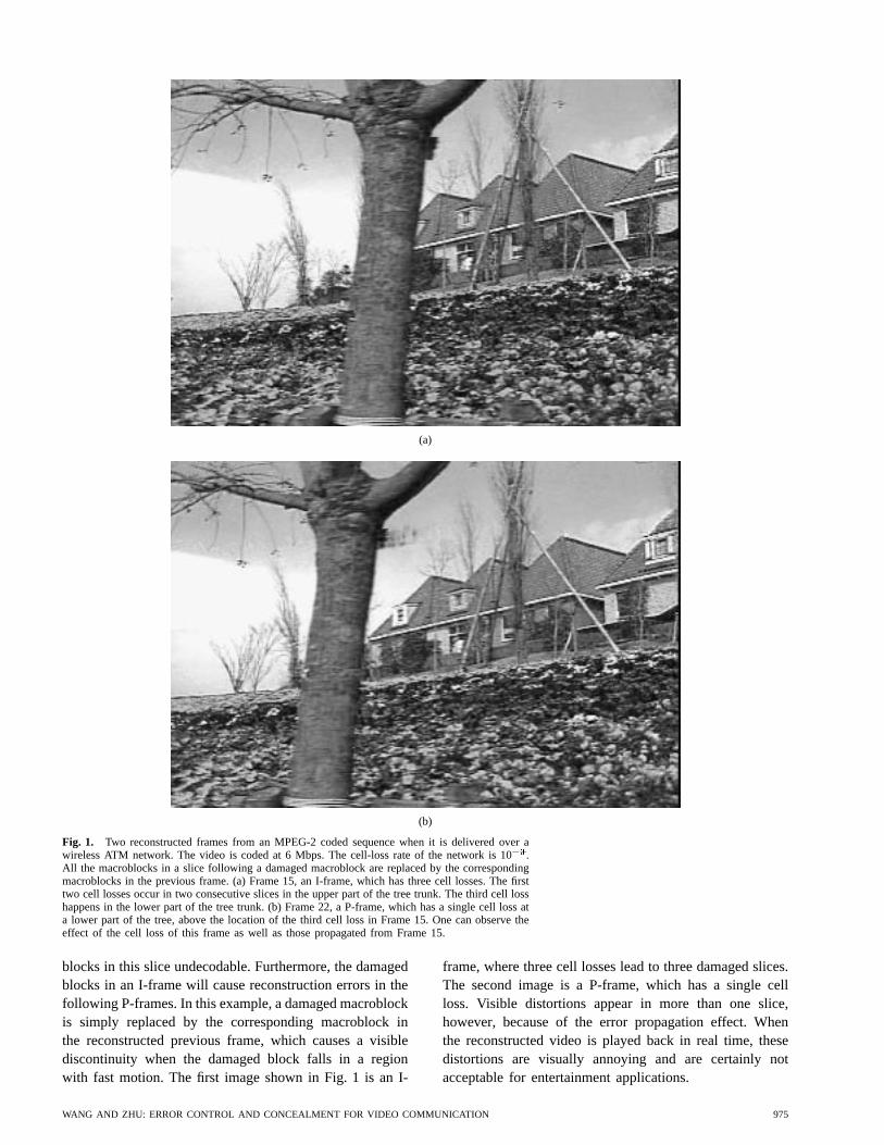
Table 2 Summary of Forward Error-Concealment Techniques
H. Summary
Table 2 summarizes the various techniques that havebeen developed for forward error concealment. All of thesetechniques achieve error resilience by adding a certainamount of redundancy in the coded bit streams, at eitherthe source coder or transport coder. Among the techniquesthat add redundancy at the source coder, some are aimed atguaranteeing a basic level of quality and providing a grace-ful degradation upon the occurrence of transmission errors(e.g., layered coding and multiple-description coding), somehelp the decoder to perform error concealment upon detec-tion of errors (e.g., robust waveform coding), while othershelp to detect bit errors and/or prevent error propagation(e.g., robust entropy coding). The transport-level protection,e.g., by using FEC and robust packetization, etc., mustcooperate with the source coder so that more importantinformation bits are given stronger protection and that asingle bit error or cell loss does not lead to a disastrouseffect. It is noteworthy that some techniques require closeinteraction between the source and transport coders (e.g.,layered coding with prioritized transport, interleaved pack-etization with restricted prediction domain), while othersassume that different substreams are treated equally (e.g.,
multiple-description coding). Note that these techniques arenot mutually exclusive; rather, they can be used together ina complementary way.
V. ERROR CONCEALMENT BY POSTPROCESSING
AT THE DECODER
It is well known that images of natural scenes have pre-dominantly low-frequency components, i.e., the color val-ues of spatial and temporally adjacent pixels vary smoothly,except in regions with sharp edges. In addition, the humaneyes can tolerate more distortion to the high-frequencycomponents than to the low-frequency components. Thesefacts can be used to conceal the artifacts caused by transmis-sion errors. In this section, we describe several techniquesthat attempt to perform error concealment at the decoder.Some of these techniques can be used in conjunction withthe auxiliary information provided by the source coder toimprove the reconstruction quality.
Because of the space limit, we will only review methodsthat have been developed for video coders using block-based motion compensation and nonoverlapping blocktransforms (the DCT in particular), which is the underlyingcore technology in all standard video codecs. With such a
WANG AND ZHU: ERROR CONTROL AND CONCEALMENT FOR VIDEO COMMUNICATION 985

coder, a frame is divided into macroblocks, which consistsof several blocks. There are typically two coding modesat the macroblock level. In the intramode, each block istransformed using block DCT, and the DCT coefficients arequantized and entropy coded. In the intermode, a motionvector is found that specifies its corresponding macroblockin a previously coded frame,5 and this motion vector andthe DCT coefficients of the prediction error block arequantized and coded. By using a self-synchronization codeword at the beginning of each scan row of macroblocks,known as a slice, typically a transmission error (eithera bit error or erasure error) will only cause damage toa single row, so that the upper and lower macroblocksof a damaged block may still be correctly received. Ifthe coded macroblocks are packetized in an interleavedmanner, than a damaged macroblock is usually surroundedin all four directions by correctly received macroblocks.In addition, if layered coding with frequency-domainpartitioning is used, a damaged macroblock may havethe coding mode, motion vector, and some low-frequencycoefficients correctly received. Last, the error events amongtwo adjacent frames are usually sufficiently uncorrelatedso that for a given damaged macroblock in the currentframe, its corresponding macroblock (as specified by themotion vector) in the previous frame is usually receivedundamaged. All the postprocessing techniques make useof the correlation between a damaged macroblock andits adjacent macroblocks in the same frame and/or theprevious frame to accomplish error concealment. Someof the techniques only apply to macroblocks coded inintramode, while others, although applicable to intercodedblocks, neglect the temporal information. In the following,we first review techniques that concentrate on recovery ofthe DCT coefficients or, equivalently, the pixel values. Wethen present techniques for recovering the coding modeand motion vectors.
A. Motion-Compensated Temporal Prediction
One simple way to exploit the temporal correlation invideo signals is by replacing a damaged macroblock withthe spatially corresponding macroblock in the previousframe. This method, however, can produce adverse vi-sual artifacts in the presence of large motion. Significantimprovement can be obtained by replacing the damagedmacroblock with the motion compensated block (i.e., theblock specified by the motion vector of the damaged block).This method is very effective when combined with layeredcoding that includes all the motion information in thebase layer [69]. Because of its simplicity, this method hasbeen widely used. In fact, the MPEG-2 standard allowsthe encoder to send the motion vectors for intracodedmacroblocks, so that these blocks can be recovered better ifthey are damaged during transmission (refer to Section IV-D1). It has been found that using motion-compensated error
5In some coders, bidirectional prediction is used, by which a macroblockin the current frame is predicted from a previous frame and a follow-ing frame. To simplify the discussion, we only consider unidirectionalprediction here.
concealment can improve the peak SNR of reconstructedframes by 1 dB at a cell-loss rate of 10 for MPEG-2coded video [24]. A problem with this approach is thatit requires knowledge of the motion information, whichmay not be available in all circumstances. When the mo-tion vectors are also damaged, they need to be estimatedfrom the motion vectors of surrounding macroblocks, andincorrect estimates of motion vectors can lead to largeerrors in reconstructed images. Another problem with thisapproach occurs when the original macroblock was codedwith intramode and the coding-mode information is dam-aged. Then, concealment with this method can lead tocatastrophic results in situations such as a scene change.Recovery of motion vectors and coding modes is discussedin Section V-E.
In [70], Kieu and Ngan considered the error-concealmentproblem in a layered coder that sends the motion vectorsand low-frequency coefficients in the base layer and high-frequency coefficients in the enhancement layer. Insteadof simply setting the high-frequency components to zerowhen the enhancement layer is damaged, it was shownthat using the high-frequency component from the motion-compensated macroblock in the previous frame can improvethe reconstructed picture quality. It is assumed that the baselayer is delivered without error. When the enhancementlayer is damaged, for each damaged macroblock, its motion-compensated macroblock is formed and the DCT is appliedto the blocks within the macroblock. The resulting high-frequency DCT coefficients are then merged with the base-layer DCT coefficients of the damaged blocks in the currentframe, and the inverse DCT is applied to these blocks toform an error-concealed macroblock.
The above techniques only make use of temporal cor-relation in the video signal. For more satisfactory recon-struction, spatial correlation should also be exploited. Thetechniques reviewed below either make use of both spatialand temporal correlation for error concealment or onlyexploit the spatial correlation.
B. Maximally Smooth Recovery
This method makes use of the smoothness property ofmost image and video signals through a constrained energyminimization approach. The minimization is accomplishedblock by block. Specifically, to estimate the missing DCTcoefficients in a block, the method minimizes a measureof spatial and temporal variation between adjacent pixelsin this block and its spatially and temporally neighboringblocks, so that the resulting estimated video signal is assmooth as possible. Wanget al. first used this approachto recover damaged blocks in still images coded usingblock-transform-based coders by making use of the spatialsmoothness only [71]. Zhuet al. later extended this methodto video coders using motion compensation and transformcoding by adding the temporal smoothness measure [19].In this latter case, the error function being minimizedis a weighted sum of a spatial difference measure anda temporal difference measure. For computational ease,the spatial and temporal difference measures are defined
986 PROCEEDINGS OF THE IEEE, VOL. 86, NO. 5, MAY 1998

Fig. 7. Illustration of spatial smoothing constraints (from [71]).An arrow between two pixels indicates that the difference betweenthese two pixels is included in the smoothness measure. The mea-sure illustrated in (a) is appropriate when only the DC coefficientis lost, while that in (b) is more effective when the DC and severallow-frequency coefficients are missing.
as the sums of squared differences between spatially andtemporally adjacent pixels, respectively. Fig. 7 illustratesthe two spatial smoothness measures proposed in [71]. Tosatisfy the constraints imposed by the received coefficients,the image block to be reconstructed is represented interms of the received coefficients, the missing coefficientsto be estimated, and the prediction block in the pre-vious frame (for intercoded blocks only). The solutionessentially consists of three linear interpolations—in thespatial, temporal, and frequency domains—from the pixelsin adjacent image blocks that have been reconstructedpreviously, the prediction block in the previous frame, andthe received coefficients for this block, respectively. Whenall the coefficients are lost in a damaged block, the solutionreduces to spatial and temporal interpolation only. If onesets the weight for the spatial difference measure to zero,then the solution is equivalent to replacing the damagedblock by the prediction block, the same as that presentedin Section V-A. On the other hand, if the weighting forthe temporal difference measure is zero, only the spatialcorrelation is used, and the solution is a linear interpolationfrom the received coefficients and the neighbor pixel data.This can be used for intracoded blocks or still images. Thereconstruction operator depends on the weighting factorused and the transform basis functions associated withthe lost coefficients. For a given loss pattern (i.e., whichcoefficients are lost), this operator can be precomputed,and the reconstruction task involves a matrix-and-vectorproduct, with a complexity similar to a block transform.
With the above reconstruction technique, simulation re-sults show that a block with its first 15 low-frequency coef-ficients lost can be recovered with acceptable quality as longas its neighboring blocks are available for spatial/temporalinterpolation6 [19]. To improve the robustness of the coder,one can interleave the coefficients of adjacent blocks beforetransmission so that a channel error will only affect spatiallydisjointed blocks. Furthermore, the coefficients can besegmented into multiple layers so that only a finite numberof loss patterns exist, and the interpolation filters for theseloss patterns can be precomputed. These enhancements
6Note that if only the high-frequency coefficients are lost, simply settingthem to zeros will in general yield satisfactory results.
have been added to an MPEG-1-like video codec, andthe reconstruction technique is invoked at the decoderonly when the layers containing low-frequency coefficientsare lost. Specifically, four layers are used: the base layercontains the coding mode, the second layer includes themotion vectors, and the third and fourth layers carry thelow- and high-frequency DCT coefficients, respectively.Simulation results show that this modified MPEG-1 systemcan yield visually acceptable quality at loss rates of 10in the first two layers and 10 in the third layer [19].
In the above work, the spatial/temporal variation is mea-sured by calculating the difference between two adjacentpixels. Such first-order smoothness measures can lead toblurred edges in the recovered image. Zhu and Wang laterinvestigated the use of second-order smoothness criteria toreduce the blurring artifacts [73]. A combination of thequadratic variation and Laplacian operator was proposed,and the reconstructed images using this measure are visuallymore pleasing than those obtained with the first-ordermeasure, with sharper edges that are smooth along the edgedirections. To further improve the reconstruction quality,an edge-adaptive smoothness measure can be used so thatthe variation along the edges is minimized but not acrossthe edges. Several techniques have been developed alongthis direction [72]. This approach requires the detection ofedge directions for the damaged blocks. This is a difficulttask, and a mistake can yield noticeable artifacts in thereconstructed images. The method using the second-ordersmoothness measure is in general more robust and can yieldsatisfactory images with lower computational cost.
C. Projection onto Convex Sets (POCS)
The method described in the previous section makesuse of the smoothness property of the image and videosignals by an energy minimization approach. An alternativeis to use the POCS method. Sun and Kwok proposed touse this method to restore a damaged image block in ablock transform coder [74]. The convex sets are derived byrequiring the recovered block to have a limited bandwidtheither isotropically (for a block in a smooth region) oralong a particular direction (for a block containing a straightedge). With this method, a combined block is formed byincluding eight neighboring blocks with the damaged block.First, this combined block is subject to an edge existencetest by using the Sobel operator. The block is classifiedas either a monotone block (i.e., with no discernible edgeorientations) or an edge block. The edge orientation isquantized to one of the eight directions equally spacedin the range of 0–180. Then, two projection operatorsare applied to the combined block, as shown in Fig. 8.The first projection operator implements a band-limitednessconstraint, which depends on the edge classifier output. Ifthe block is a monotone block, then the block is subjectto an isotropic band-limitedness constraint, accomplishedby an isotropic low-pass filter. On the other hand, if theblock classifier output is one of the eight edge directions,then a bandpass filter is applied along that direction. Thefiltering operation is implemented in the Fourier trans-
WANG AND ZHU: ERROR CONTROL AND CONCEALMENT FOR VIDEO COMMUNICATION 987

Fig. 8. Illustration of the adaptive POCS iterative restorationprocess (from [74]).
form domain. The second projection operator implements arange constraint and truncates the output value from thefirst operator to the range of [0,255]. For pixels in theedge blocks that are correctly received, their values aremaintained. These two projection operations are appliedalternatingly until the block does not change any moreunder further projections. It was found that five to teniterations are usually sufficient when a good initial estimateis available. Note that this technique only makes use ofspatial information in the reconstruction process and istherefore applicable to intracoded blocks or still images.For intercoded blocks, one way to make use of the temporalinformation is by using the motion-compensated blockin the previous frame as the initial estimate and thenusing the technique presented here to further improve thereconstruction accuracy.
D. Spatial- and Frequency-Domain Interpolation
One implication of the smoothness property of the videosignal is that a coefficient in a damaged block is likelyto be close to the corresponding coefficients (i.e., withthe same frequency index) in spatially adjacent blocks.In [75], Hemami and Meng proposed to interpolate eachlost coefficient in a damaged block from its correspondingcoefficients in its four neighbor blocks. The interpolationcoefficients are estimated by minimizing a spatial differencemeasure given in [71]. When all the coefficients for thedamaged block are lost, this frequency-domain interpolationis equivalent to interpolating each pixel in the block fromthe corresponding pixels in four adjacent blocks ratherthan the nearest available pixels. Because the pixels usedfor interpolation are eight pixels away in four separatedirections, the correlation between these pixels and themissing pixel is likely to be small, and the interpolationmay not be accurate. To improve the estimation accuracy,Aign and Fazel proposed to interpolate pixel values within adamaged macroblock from its four 1-pixel-wide boundaries[76]. Two methods are proposed to interpolate the pixelvalues. In the first method, a pixel is interpolated fromtwo pixels in its two nearest boundaries, as shown inFig. 9(a). In the second method, shown Fig. 9(b), a pixelin the macroblock is interpolated from the pixels in all fourboundaries.
As with the POCS method, the above schemes onlymake use of the spatial smoothness property and are mainlytargeted for still images or for intracoded blocks in video.For intercoded frames, the frequency-domain interpolationmethod of [75] cannot be applied because the DCT coeffi-
(a)
(b)
Fig. 9. Spatial interpolation for error concealment. (a) Blockbased. (b) Macroblock based (adapted from Figs. 1 and 2 in [76]).
cients of prediction errors in adjacent blocks are not highlycorrelated. The spatial-domain interpolation can, however,be applied to the original pixel values (not the predictionerror values).
Due to the smoothness properties of natural images, thecorrelation between high-frequency components of adjacentblocks is small. In [77], only the DC (zero frequency)and the lowest five AC (nonzero frequency) coefficientsof a damaged block are estimated from the top and bottomneighboring blocks, while the rest of the AC coefficients areforced to be zeros. The DC values are linearly interpolated,and the five AC coefficients are synthesized according tothe method specified in [78].
E. Recovery of Motion Vectors and Coding Modes
In the techniques described in Sections V-A to V-D,it is assumed that the coding mode and motion vectorsare correctly received. If the coding mode and motionvectors are also damaged, they have to be estimated inorder to use these methods for recovering lost coefficients.Based on the same assumption about spatial and temporalsmoothness, the coding mode and motion vectors can besimilarly interpolated from that of spatially and temporallyadjacent blocks.
988 PROCEEDINGS OF THE IEEE, VOL. 86, NO. 5, MAY 1998

(a)
(b)
Fig. 10. Estimation of coding mode for MPEG-2. (a) P-frame.(b) B-frame. (Adapted from [77].)
For estimation of coding modes, the reconstructionscheme in [19] simply treats a block with a damaged codingmode as an intracoded block and recovers the block usinginformation from spatially adjacent undamaged blocks only.This is to prevent any catastrophic effect when a wrongcoding mode is used for such cases as scene change.Fig. 10 shows a more sophisticated scheme of estimatingthe macroblock coding mode from those of its top andbottom neighboring macroblocks for MPEG-2 coded video[77].
For estimation of lost motion vectors, the followingmethods have been proposed:
a) simply setting the motion vectors to zeros, whichworks well for video sequences with relatively smallmotion;
b) using the motion vectors of the corresponding blockin the previous frame;
c) using the average of the motion vectors from spatiallyadjacent blocks;
d) using the median of motion vectors from the spatiallyadjacent blocks [79].
Typically, when a macroblock is damaged, its horizon-tally adjacent macroblocks are also damaged, and hencethe average or median is taken over the motion vectorsabove and below. It has been found that the last methodproduces the best reconstruction results [79], [80]. Themethod in [81] goes one step further. It selects among
essentially the above four methods, depending on whichone yields the least boundary matching error. This error isdefined as the sum of the variations along the one-pixel-wide boundary between the recovered macroblock and theone above it, to its left, and below it, respectively. It isassumed that these neighboring macroblocks have beenreconstructed previously, and for the damaged macroblock,only the motion vector is missing. In the event that theprediction error for this macroblock is also lost, then foreach candidate motion vector, the boundary matching erroris calculated by assuming that the prediction error of thedamaged macroblock is the same as the top macroblock,the left one, the one below, or zero. The combination ofthe motion vector and the prediction error that yields thesmallest boundary matching error is the final estimationsolution. It was shown that this method yields better visualreconstruction quality than all of the previous four methods.
F. Summary
All the error-concealment techniques recover the lostinformation by making use of somea priori knowledgeabout the image/video signals, primarily the temporal andspatial smoothness property. The maximally smooth re-covery technique enforces the smoothness constraint byminimizing the roughness of the reconstructed signal. ThePOCS method, on the other hand, iteratively projects thereconstructed image block onto the convex sets deter-mined by the received coefficients and the smoothnessconstraint determined from the estimated edge directionof the block. Although generally giving more accurateresults than the optimization approach, the POCS methodis computationally more intensive, as it requires manyiterations and estimation of edge directions. The inter-polation method can be considered as a special case ofthe energy minimization approach when only the spatialdifference measure is minimized. A problem with the directspatial-domain interpolation approach is that it ignoresthe received coefficients in a damaged block. Both thePOCS and the interpolation approaches only make use ofspatial correlation. On the other hand, with the energyminimization framework used in the maximally smoothrecovery method, both the spatial and temporal correlationcan be exploited easily. The pros and cons of differentmethods are summarized in Table 3.
The reconstruction methods reviewed here are fortransform-based coders using nonoverlapping transforms.Error-concealment techniques have also been developedfor other coding methods, including subband [82]–[84],LOT [85], [86], and Walsh transform [87]. Fuzzy logichas also been used to recover high-frequency componentsthat cannot normally be recovered by the smoothing andinterpolation methods presented in this section [88]. Last,besides performing error concealment in the source-coderdomain, as done by the techniques presented in this section,it is also possible to use residual redundancy from thesource coder in the channel coder for error concealment.Since the output symbols of any source coder are notcompletely uncorrelated, this intersymbol correlation can
WANG AND ZHU: ERROR CONTROL AND CONCEALMENT FOR VIDEO COMMUNICATION 989

Table 3 Summary of Postprocessing Techniques for Error Concealment
be used to improve the performance of the channel decoderin the presence of transmission errors. In [89], Sayood andBorkenhagen proposed to use a Viterbi decoder in front ofthe source decoder for this purpose.
VI. ENCODER AND DECODER INTERACTIVE
ERROR CONCEALMENT
In the previous two sections, we described various tech-niques for error concealment from either the encoder orthe decoder side, with little interaction between the two.Conceivably, if a backward channel from the decoder to theencoder is available, better performance can be achievedif the encoder and decoder cooperate in the process oferror concealment. This cooperation can be realized ateither the source coding or transport level. At the sourcecoder, coding parameters can be adapted based on thefeedback information from the decoder. At the transportlevel, the feedback information can be employed to changethe percentage of the total bandwidth used for FEC orretransmission. In this section, we first describe severaltechniques that adapt the source-coding strategy basedon the feedback information from the decoder. We thenpresent a few schemes that vary transport level control.Retransmission, when used together with a conventionaldecoder, leads to decoding delays that may be unacceptablefor real-time applications. Two novel schemes that counterthis problem are described next. The first approach avoidsthe decoding delay by remembering the trace of damagedblocks at the decoder. The second scheme sends multiplecopies of the lost data in each retransmission trial toreduce the number of retransmissions required. Althoughthis technique can be applied in various video applications,we focus on its application in Internet video streaming.These two approaches are presented in more detail thanother methods reviewed in this paper because they havenot appeared in journal publications.
A. Selective Encoding for Error Concealment
The error-concealment problem would not be such animportant issue for most real-time video-transmission appli-cations if the encoder did not use prediction and thereforea bit error or packet loss did not cause error propagation.If errors only persist for one or two frames, the humaneyes can hardly perceive the effect because it is too short.Temporal prediction is an indispensable building block inany video coder, however, because there is tremendousredundancy between adjacent video frames. Therefore, ifthe decoder can provide information about the locations ofdamaged parts to the encoder, the encoder can treat theseareas differently so that the effect of error propagation canbe either reduced or eliminated. One simple technique alongthis direction is that whenever the decoder detects an error,it sends a request to the encoder so that the next video frameis coded in intramode. This way, the error propagation willbe stopped in about one round-trip time. Intracoding typi-cally will reduce the compression gain, however, and hencedegrade the video quality under the same bit-rate budget.
To reduce the bit-rate increase caused by intracoding,only part of the image needs intracoding due to the limitedmotion vector range [90], [91]. To further improve thecoding efficiency, Wada proposed two schemes to performselective recovery using error concealment [92]. When apacket loss is detected, the decoder sends the identityinformation of damaged blocks to the encoder. At thesame time, error concealment is performed on the damagedblocks. Then normal decoding continues at the decoder. Atthe encoder side, two methods are proposed to stop errorpropagation at the decoder. In the first method, the affectedpicture area is calculated from the point of damaged blocksup to the currently encoded frame, as shown in Fig. 11(a).Then encoding is continued without using the affectedarea for prediction. Note that encoding without using the
990 PROCEEDINGS OF THE IEEE, VOL. 86, NO. 5, MAY 1998

(a)
(b)
Fig. 11. Selective error concealment proposed by Wada. (a)Method A. (b) Method B. (From [92].)
affected area does not necessarily mean intracoding. Inthe second method, shown in Fig. 11(b), the same error-concealment procedure as that performed at the decoderis also carried out for the damaged blocks at the encoder.Then a local decoding is reexecuted from the point of theconcealed blocks up to the currently encoded blocks. Thisis accomplished by using the transmitted data stored in theencoder transmission buffer so that the encoder’s predictionframe buffer matches that at the decoder.
Similar to the above method, the H.263 standard [2]defines areference picture selection mode,which is aimed atproviding error resilience. In this method, both the encoderand the decoder have multiple prediction frame buffers.Fig. 12 shows a block diagram of such an encoder. Besidesvideo data, the encoder and decoder exchange messagesabout what is correctly received and what is not. From thisinformation, the encoder determines which frame buffershave been damaged at the decoder. Then the encoderwill use an undamaged frame buffer for prediction. Theinformation for the selected prediction frame buffer is alsoincluded in the encoded bit stream so that the decoder canuse the same frame buffer for prediction.
Horne and Reibman [93] proposed to send observedcell-loss statistics back to the encoder, which then adaptsits coding parameters to match the prevailing channelconditions. More intrablocks and shorter slices are usedwhen the loss rate is high, for enhanced error resilience,while fewer intrablocks and longer slices are invoked whenthe error rate is low, for improved compression efficiency.
B. Adaptive Transport for Error Concealment
In the last section, several techniques were described thatadapt the source-coding strategy at the encoder based onfeedback information from the decoder. In this section,we present several schemes that employ the feedbackinformation for adjusting transport-level decisions. First, thetransport controller can negotiate with the destination theretransmission of critical information that is lost. Retrans-mission has been used very successfully for nonreal-timedata transmission, but it has been generally considered asunacceptable for real-time video applications because ofthe delay incurred. However, this viewpoint has changedslightly in the last few years. It has been realized that evenfor a coast-to-coast interactive service, one retransmissionadds only about 70 ms of delay, which can be acceptable[94]. For one-way real-time video applications such asInternet video streaming and broadcast, the delay allowancecan be further relaxed to a few seconds so that severalretransmissions are possible. Retransmission has also beenconsidered inappropriate for multipoint video conferencingbecause the retransmission requests from a large numberof decoders can overwhelm the encoder. However, whena multipoint control unit (MCU) is used in a multipointconference, the paths between the encoder and the MCU,and between the MCU and the decoders, are simply pointto point. Retransmission can be applied in these pathsseparately. Another concern about using retransmissionis that it may worsen the problem because it will addmore traffic on the network and thus further increase thepacket-loss rate. However, if retransmission is controlledappropriately, the end-to-end quality can be improved. Forexample, the encoder can reduce its current output rate sothat the sum of the encoder output and the retransmitteddata is kept below a given total data rate.
In spite of the above considerations, retransmission hasnot been used in most video-communications systems. Thisis mainly because most video applications are currentlycarried over ISDN networks, where the transmission errorrate is relatively low. The error-propagation problem iscircumvented by coding an entire frame in the intramodeat the encoder when it is informed of the occurrence of atransmission error by the decoder. Recently, there has beenan increasing interest in video communications over verylossy networks such as the Internet and wireless networks,and retransmission is expected to be deployed under theseenvironments. In fact, both H.323 and H.324 standards havedefined mechanisms of using retransmission for combatingtransmission errors [7], [9].
Because of its ubiquity, the Internet has been envisionedas the future platform for carrying various digital video
WANG AND ZHU: ERROR CONTROL AND CONCEALMENT FOR VIDEO COMMUNICATION 991

Fig. 12. The reference picture selection mode of H.263.
services. However, the current Internet is a packet-basednetwork with a best-effort delivery service. There is noend-to-end guaranteed QoS. Packets may be discarded dueto buffer overflow at intermediate network nodes such asswitches or routers or considered as lost due to excessivelong queuing delay. Without any retransmission, experi-ments show that the packet loss rate is in the range of2–10%, while the round-trip delay is about 50–100 mson an average and can be more than 2 s in coast-to-coastconnections [95]. With such error and delay characteristics,the achievable QoS is usually poor. Marasliet al. proposedto achieve better service quality in terms of delay and lossrate by using retransmission over an unreliable network[96]. Instead of trying retransmission indefinitely to recovera lost packet, as in TCP, the number of retransmissiontrials is determined by the desired delay. Smith proposed acyclical user datagram protocol, which places the base-layerpackets of a layered coder in the front of the transmissionqueue to increase the number of retransmission trials forthe base layer [97]. Cenet al. and Chenet al. proposedto reduce the video output rate at the encoder when thenetwork is congested [98], [99]. The feedback informationabout the network condition can be obtained by using thedelay and loss-rate statistics at the decoder.
C. Retransmission Without Waiting
To make use of the retransmitted data, a typical imple-mentation of the decoder will have to wait for the arrival
of the requested retransmission data before processingsubsequently received data. This will not only freeze thedisplayed video momentarily, but also introduce a certainform of delay. If the decoder chose to decode faster thanits normal speed after the arrival of retransmission, thanonly a few video frames would be displayed later thanits intended display time; this delay is known as transitdelay. On the other hand, the decoder can decode anddisplay all the subsequent frames with a fixed delay, calledaccumulation delay. In the following, we describe a schemethat uses retransmission for recovering lost information forpredictive video coders but does not introduce the delaynormally associated with retransmission [100]. A similartechnique was developed by Ghanbari, which is motivatedby the desire of making use of late cells in an ATM network[101].
With this scheme, when a video data unit is damaged, aretransmission request is sent to the encoder for recoveringthe damaged data. Instead of waiting for the arrival ofretransmitted data, the damaged video part is concealed bya chosen error-concealment method. Then normal decodingis continued, while a trace of the affected pixels and theirassociated coding information (coding mode and motionvectors) is recorded. The affected pixels refer to thosethat are subject to error-propagation effect of the damagedblocks. Upon the arrival of the retransmitted data, theaffected pixels are corrected, so that they are reproducedas if no transmission loss had occurred. The correction
992 PROCEEDINGS OF THE IEEE, VOL. 86, NO. 5, MAY 1998
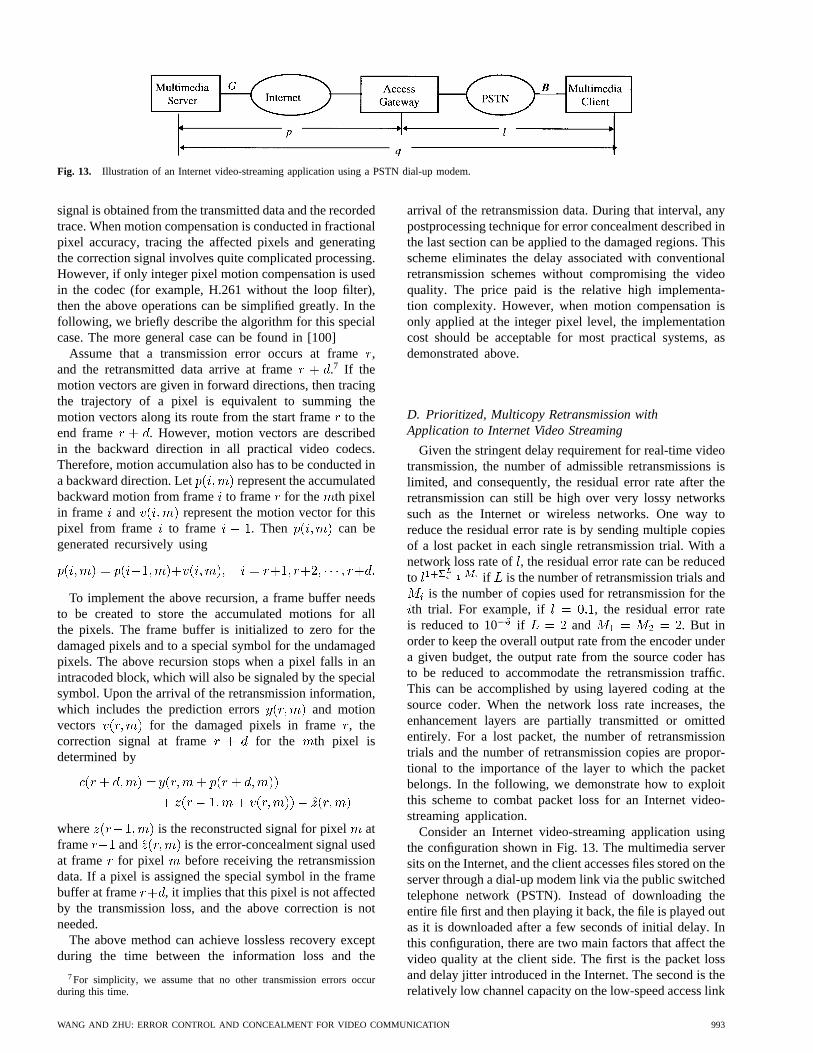
Fig. 13. Illustration of an Internet video-streaming application using a PSTN dial-up modem.
signal is obtained from the transmitted data and the recordedtrace. When motion compensation is conducted in fractionalpixel accuracy, tracing the affected pixels and generatingthe correction signal involves quite complicated processing.However, if only integer pixel motion compensation is usedin the codec (for example, H.261 without the loop filter),then the above operations can be simplified greatly. In thefollowing, we briefly describe the algorithm for this specialcase. The more general case can be found in [100]
Assume that a transmission error occurs at frame,and the retransmitted data arrive at frame .7 If themotion vectors are given in forward directions, then tracingthe trajectory of a pixel is equivalent to summing themotion vectors along its route from the start frameto theend frame . However, motion vectors are describedin the backward direction in all practical video codecs.Therefore, motion accumulation also has to be conducted ina backward direction. Let represent the accumulatedbackward motion from frameto frame for the th pixelin frame and represent the motion vector for thispixel from frame to frame . Then can begenerated recursively using
To implement the above recursion, a frame buffer needsto be created to store the accumulated motions for allthe pixels. The frame buffer is initialized to zero for thedamaged pixels and to a special symbol for the undamagedpixels. The above recursion stops when a pixel falls in anintracoded block, which will also be signaled by the specialsymbol. Upon the arrival of the retransmission information,which includes the prediction errors and motionvectors for the damaged pixels in frame, thecorrection signal at frame for the th pixel isdetermined by
where is the reconstructed signal for pixel atframe and is the error-concealment signal usedat frame for pixel before receiving the retransmissiondata. If a pixel is assigned the special symbol in the framebuffer at frame , it implies that this pixel is not affectedby the transmission loss, and the above correction is notneeded.
The above method can achieve lossless recovery exceptduring the time between the information loss and the
7For simplicity, we assume that no other transmission errors occurduring this time.
arrival of the retransmission data. During that interval, anypostprocessing technique for error concealment described inthe last section can be applied to the damaged regions. Thisscheme eliminates the delay associated with conventionalretransmission schemes without compromising the videoquality. The price paid is the relative high implementa-tion complexity. However, when motion compensation isonly applied at the integer pixel level, the implementationcost should be acceptable for most practical systems, asdemonstrated above.
D. Prioritized, Multicopy Retransmission withApplication to Internet Video Streaming
Given the stringent delay requirement for real-time videotransmission, the number of admissible retransmissions islimited, and consequently, the residual error rate after theretransmission can still be high over very lossy networkssuch as the Internet or wireless networks. One way toreduce the residual error rate is by sending multiple copiesof a lost packet in each single retransmission trial. With anetwork loss rate of, the residual error rate can be reducedto if is the number of retransmission trials and
is the number of copies used for retransmission for theth trial. For example, if , the residual error rate
is reduced to 10 if and . But inorder to keep the overall output rate from the encoder undera given budget, the output rate from the source coder hasto be reduced to accommodate the retransmission traffic.This can be accomplished by using layered coding at thesource coder. When the network loss rate increases, theenhancement layers are partially transmitted or omittedentirely. For a lost packet, the number of retransmissiontrials and the number of retransmission copies are propor-tional to the importance of the layer to which the packetbelongs. In the following, we demonstrate how to exploitthis scheme to combat packet loss for an Internet video-streaming application.
Consider an Internet video-streaming application usingthe configuration shown in Fig. 13. The multimedia serversits on the Internet, and the client accesses files stored on theserver through a dial-up modem link via the public switchedtelephone network (PSTN). Instead of downloading theentire file first and then playing it back, the file is played outas it is downloaded after a few seconds of initial delay. Inthis configuration, there are two main factors that affect thevideo quality at the client side. The first is the packet lossand delay jitter introduced in the Internet. The second is therelatively low channel capacity on the low-speed access link
WANG AND ZHU: ERROR CONTROL AND CONCEALMENT FOR VIDEO COMMUNICATION 993

Table 4 Summary of Interactive Error-Concealment Techniques
from the client to the access gateway. In general, the lossrate in the PSTN is much lower than that in the Internet.
To cope with the high loss rate in the network, layeredcoding and multicopy retransmission are used. For a lostpacket, more than one copy of retransmission is applied toboth increase the probability of successful retransmissionand reduce the number of retransmission trials, thus reduc-ing delay. The number of retransmission copies for eachlayer is dependent on its importance to the reconstructedvideo quality. To avoid packet discarding at the accessgateway, traffic arriving at the gateway cannot be greaterthan the access link capacity. In addition, the combined dataoutput from the server (which consists of the streaming dataand retransmission data) should be smaller than a certainvalue so as not to jam the Internet.
Let be the number of layers used in coding the originalmultimedia data, where , and let be the originaldata rate for layer. Further, let represent the number ofretransmission copies for layerin the th retransmissionattempt and the maximum retransmission trials allowed.Because of retransmission, the streaming rate for eachlayer , which is defined as the data rate excluding theretransmission data, may be different from the originalcoded data rate . Hence, the combined data output fromthe server has to satisfy the following relationship:
where is the end-to-end packet-loss rate,is the max-imum data rate allowed by the server, is the channelcapacity of the access link, andis the packet-loss rate inthe Internet. In the above equation, the left side representsthe combined traffic output from the server, with the firstterm accounting for the streaming rate and the second termfor the retransmission rate. In general,is unknown at boththe server and the client. Butcan be measured at either theclient or the server, and the packet-loss rate in the accesslink can also be obtained from the underlying physicallayer or link layer. Then can be derived according to
.To obtain the best video quality, the parameters
and have to be chosen jointly. The maximum number ofretransmissions is typically determined by the acceptableinitial playout delay and the round-trip delay. For the more
important base layers, should be bigger than that forthe enhancement layers. In addition, as the number ofretransmission trials increases, and hence the remainingretransmission window narrows down, should increasefor the base layer and decrease for the enhancement layersto yield more bandwidth for the base layer. For example,assume kb/s,kb/s, kb/s, kb/s, and kb/s.With chosen as , we canachieve streaming rates of kb/s, kb/s, and
kb/s, with the residual error rates for the threelayers being 10 , 10 , and 10 , respectively.
Because of the characteristics of the current Internet,sophisticated transport mechanisms such as the one pre-sented in this section have to be applied to obtain anacceptable service quality. The permissible delay allowedby the video-streaming application makes it possible to useseveral retransmission trials so that a very low residual errorrate can be achieved for the base layer. Like the schemepresented in the previous section, the improvement in theservice quality is accomplished at the expense of an addedimplementation complexity. The sever and client have tonot only support the prioritized multicopy retransmissionprotocol but also implement the layered coder structure.
E. Summary
In this section, we reviewed several techniques in thearea of interactive error concealment. For applications thathave a backward channel available from the decoder tothe encoder, this class of methods should give the bestperformance because the redundancy is added only whenan error occurs. This is especially important for channelsthat have bursty error characteristics. Table 4 summarizesthe techniques we presented in this section. Note that thesetechniques can be used in conjunction with methods inthe other two categories. In fact, the prioritized multicopyretransmission scheme is a combination of retransmissionand layered coding.
VII. CONCLUDING REMARKS
In this paper, various techniques have been described forperforming error concealment in real-time video commu-nication. Depending on channel error characteristics andsystem configuration and requirements, some techniques aremore effective than others. The burstiness of transmission
994 PROCEEDINGS OF THE IEEE, VOL. 86, NO. 5, MAY 1998

errors has a significant impact on the choice of algorithms.For a channel with bursty errors, forward error-concealmenttechniques may not be appropriate. This is because the over-head introduced by forward error concealment is wastedwhen the channel is error free, and such overhead is notvery helpful when a burst error occurs. Retransmissionmay be more suitable since it only introduces the overheadwhen needed. The existence of a backward channel fromthe decoder to the encoder also affects the deployment ofsome schemes. In applications such as broadcast, wherethere is no backward channel, none of the interactive error-concealment techniques can be applied. The postprocessingtechniques can be applied in any circumstances. However,the effectiveness of such techniques is limited by the avail-able information. Also, some techniques may be either toocomplicated for cost-effective implementation or introduceunacceptable processing delay for real-time applications.Aside from the delay and complexity issues, one importantcriterion for comparing different schemes is the requiredconcealment redundancy in source and/or channel codersto achieve the same degree of error protection. A faircomparison is difficult to obtain, however, because thesetechniques are usually developed for very different transportenvironments.
For future research, although more effective error-concealment approaches are still called for, more emphasisshould be placed at the system-level design and optimiza-tion where the encoding algorithm, transport protocol,and postprocessing method should be designed jointly tominimize the combined distortion due to both compressionand transmission. In addition, an optimal system shouldadapt its source-coding algorithm and transport-controlmechanism to the network conditions so that the bestend-to-end service quality is achieved. For example,a recently established transport protocol for mobilemultimedia communication can provide several levels oferror-resilience performance [102]. The system can hopbetween difference levels adaptively based on the errorcharacteristics of the channel. However, there is very littleinteraction between the source coder and transport layerin terms of error concealment. An optimal system shouldallocate the concealment redundancy between the sourcecoder and transport layers adaptively based on the channelenvironment so as to optimize the reconstructed videoquality for a given decoder error-concealment capability.This remains a challenging task for future research andstandardization efforts.
ACKNOWLEDGMENT
The authors wish to thank Dr. A. Reibman, AT&T Labs-Research, for carefully reading through the manuscript andproviding many useful suggestions and critiques, as well asfor her generous help in generating the images in Fig. 1.The authors also appreciate the constructive comments andsuggestions from the anonymous reviewers, which havegreatly improved the presentation of the paper.
REFERENCES
[1] “Video codec for audiovisual services at 64 kbits,” Interna-tional Telecommunications Union, Geneva, Switzerland, ITU-TRecommendation H.261, 1993.
[2] “Video coding for low bitrate communication,” InternationalTelecommunications Union, Geneva, Switzerland, ITU-T Rec-ommendation H.263, 1998.
[3] “Information technology—Generic coding of moving picturesand associated audio information—Part 2: Video,” ISO/IEC DIS13818-2, 1994.
[4] “Frame structure for a 64 to 1920 kbit/s channel in audio-visual teleservices,” International Telecommunications Union,Geneva, Switzerland, ITU-T Recommendation H.221, 1993.
[5] “Narrow-band visual telephone systems and terminal equip-ment,” International Telecommunications Union, Geneva,Switzerland, ITU-T Recommendation H.320, 1993.
[6] “Multiplexing protocol for low bitrate multimedia commu-nication,” International Telecommunications Union, Geneva,Switzerland, ITU-T Recommendation H.223, 1995.
[7] “Terminal for low bitrate multimedia communication,” Interna-tional Telecommunications Union, Geneva, Switzerland, ITU-TDraft Recommendation H.324, Dec. 1997.
[8] “Media stream packetization and synchronization on non-guaranteed quality of services LANs,” International Telecom-munications Union, Geneva, Switzerland, ITU-T Recommen-dation H.225.0, 1996.
[9] “Telephone systems and equipment for local area networkswhich provide a non-guaranteed quality of service,” Interna-tional Telecommunications Union, Geneva, Switzerland, ITU-TRecommendation H.323, Visual 1996.
[10] N. Ohta,Packet Video: Modeling and Signal Processing. Nor-wood, MA: Artech House, 1994.
[11] S. Lin and D. J. Costello,Error Control Coding: Fundamentalsand Applications Englewood Cliffs, NJ: Prentice-Hall, 1983.
[12] K. N. Ngan and R. Stelle, “Enhancement of PCM and DPCMimages corrupted by transmission errors,”IEEE Trans. Com-mun., vol. COM-30, pp. 257–265, Jan. 1982.
[13] K. M. Rose and A. Heiman, “Enhancement of one-dimensionalvariable-length DPCM images corrupted by transmission er-rors,” IEEE Trans. Commun., vol. 37, pp. 373–379, Apr. 1989.
[14] O. R. Mitchell and A. J. Tabatabai, “Channel error recovery fortransform image coding,”IEEE Trans. Commun., vol. COM-29,pp. 1754–1762, Dec. 1981.
[15] W.-M. Lam and A. Reibman, “An error concealment algorithmfor images subject to channel errors,”IEEE Trans. ImageProcessing, vol. 4, May 1995, pp. 533–542.
[16] C. E. Shannon, “A mathematical theory of communication,”Bell Syst. Tech. J., vol. 27, pp. 379–423, 623–656, 1948.
[17] S. Vembu, S. Verdu, and Y. Steinberg, “The source-channelseparation theorem revisited,”IEEE Trans. Inform Theory, vol.41, pp. 44–54, Jan. 1995.
[18] M. Ghanbari, “Two-layer coding of video signals for VBRnetworks,”IEEE J. Select. Areas Commun., vol. 7, pp. 801–806,June 1989.
[19] Q.-F. Zhu, Y. Wang, and L. Shaw, “Coding and cell lossrecovery for DCT-based packet video,”IEEE Trans. CircuitsSyst. Video Technol., vol. 3, pp. 248–258, June 1993.
[20] K. Ramchandran, A. Ortega, and K. M. Uz, “Multiresolutionbroadcast for digital HDTV using joint source channel coding,”IEEE J. Select. Areas Commun., vol. 11, pp. 6–23, Jan. 1993.
[21] Y.-Q. Zhang, Y. J. Liu, and R. L. Pickholtz, “Layered imagetransmission over cellular radio channels,”IEEE Trans. Veh.Technol., vol. 43, pp. 786–796, Aug. 1994.
[22] M. Khansari and M. Vetterli, “Layered transmission of signalsover power-constrained wireless channels,” inProc. ICIP-95,Washington, DC, Oct. 1995, vol. III, pp. 380–383.
[23] M. Kansari et al., “Low bit rate video transmission over fad-ing channels for wireless microcellular systems,”IEEE Trans.Circuits Syst. Video Technol., vol. 6, pp. 1–11, Feb. 1996.
[24] R. Aravind, M. R. Civanlar, and A. R. Reibman, “Packet lossresilience of MPEG-2 scalable video coding algorithms,”IEEETrans. Circuits Syst. Video Technol., vol. 6, pp. 426–435, Oct.1996.
[25] J. K. Wolf, A. Wyner, and J. Ziv, “Source coding for multipledescriptions,”Bell Syst. Tech. J., vol. 59, pp. 1417–1426, Oct.1980.
[26] L. Ozarow, “On a source coding problem with two channels andthree receivers,”Bell Syst. Tech. J., vol. 59, p. 1921, Dec. 1980.
WANG AND ZHU: ERROR CONTROL AND CONCEALMENT FOR VIDEO COMMUNICATION 995

[27] A. A. El-Gamal and T. M. Cover, “Achievable rats for multipledescriptions,” IEEE Trans. Inform. Theory, vol. IT-28, pp.851–857, Nov. 1982.
[28] Y. Wang and D. Chung, “Non-hierarchical signal decompositionand maximally smooth reconstruction for wireless video trans-mission,” inMobile Multimedia Communications, D. Goodmanand D. Raychaudhuri, Eds. New York: Plenum, to be pub-lished.
[29] A. S. Tom, C. L. Yeh, and F. Chu, “Packet video for cellloss protection using deinterleaving and scrambling,” inProc.ICASSP’91, Toronto, Canada, Apr. 1991, pp. 2857–2850.
[30] V. A. Vaishampayan, “Design of multiple description scalarquantizers,”IEEE Trans. Inform. Theory, vol. 39, pp. 821–834,May 1993.
[31] V. A. Vaishampayan and J. Domaszewicz, “Design of entropyconstrained multiple description scalar quantizers,”IEEE Trans.Inform. Theory, vol. 40, pp. 245–251, Jan. 1994.
[32] V. A. Vaishampayan, “Application of multiple description codesto image and video transmission over lossy networks,” inProc.7th Int. Workshop Packet Video, Brisbane, Australia, Mar. 1996,pp. 55–60.
[33] J.-C. Batllo and V. A. Vaishampayan, “Asymptotic performanceof multiple description transform codes,”IEEE Trans. Inform.Theory,vol. 43, pp. 703–707, Mar. 1997.
[34] Y. Wang, M. T. Orchard, and A. R. Reibman, “Multiple de-scription image coding for noisy channels by pairing transformcoefficients,” in Proc. 1997 IEEE 1st Workshop MultimediaSignal Processing, Princeton, NJ, June 1997, pp. 419–424.
[35] M. T. Orchard, Y. Wang, V. Vaishampayan, and A. R. Reibman,“Redundancy rate-distortion analysis of multiple descriptioncoding using pairwise correlating transforms,” inProc. IEEEInt. Conf. Image Process (ICIP97), Santa Barbara, CA, Oct1997, vol. I, pp. 608–611.
[36] S. S. Hemami, “Reconstruction-optimized lapped orthogonaltransforms for robust image transmission,”IEEE Trans. CircuitsSyst. Video Technol., vol. 6, pp. 168–181, Apr. 1996.
[37] D. Chung and Y. Wang, “Multiple description image codingusing signal decomposition and reconstruction based on lappedorthogonal transforms,” unpublished.
[38] H. S. Malvar and D. H. Staelin, “The LOT: Transform codingwithout blocking effects,”IEEE Trans. Acoust., Speech, SignalProcessing, vol. 38, pp. 553–559, Apr. 1989.
[39] M. T. Orchard, Y. Wang, A. R. Reibman, and V. Vaishampayan,“Multiple description coding by pairing transform coefficients,”unpublished.
[40] J. J. Spilker, Jr.,Digital Communications By Satellite. Engle-wood Cliffs, NJ: Prentice-Hall, 1977.
[41] J. Kurtenbach and P. A. Wintz, “Quantizing for noisy channels,”IEEE Trans. Commun. Technol., vol. CT-17, pp. 291–302, Apr.1969.
[42] N. Farvardin and V. Vaishampayan, “Optimal quantizer designfor noisy channels: an approach to combined source-channelcoding,” IEEE Trans. Inform. Theory, vol. IT-38, pp. 827–838,Nov. 1987.
[43] J. W. Modestino and D. G. Daut, “Combined source-channelcoding of images,”IEEE Trans. Commun., vol. COM-7, pp.1644–1659, Nov. 1979.
[44] J. W. Modestino, D. G. Daut, and A. L. Vickers, “Combinedsource-channel coding of images using the block cosine trans-form,” IEEE Trans. Commun., vol. COM-29, pp. 1261–1273,Sept. 1981.
[45] V. A. Vaishampayan and N. Farvardin, “Optimal block co-sine transform image coding for noisy channels,”IEEE Trans.Commun., vol. 38, pp. 327–336, Mar. 1990.
[46] S. S. Hemami and R. M. Gray, “Image reconstruction usingvector quantized linear interpolation,” inProc. ICASSP’94,Australia, May 1994, pp. V-629–632.
[47] S. Wenger, “Video redundancy coding in H.263” in Proc.AVSPN, Aberdeen, U.K., Sept. 1997.
[48] J. C. Maxted and J. P. Robinson, “Error recovery for variablelength codes,”IEEE Trans. Inform. Theory, vol. IT-31, pp.794–801, 1985.
[49] T. J. Ferguson and J. H. Ranowitz, “Self-synchronizingHuffman codes,” IEEE Trans. Inform. Theory, vol. IT-30,pp. 687–693, July 1984.
[50] P. G. Neumann, “Self-synchronizing sequential coding with lowredundancy,”Bell Syst. Tech. J., vol. 50, pp. 951–981, Mar.1971.
[51] S.-M. Lei and M.-T Sun, “An entropy coding system for digitalHDTV applications,”IEEE Trans. Circuits Syst. Video Technol.,vol. 1, pp. 147–154, Mar. 1991.
[52] W.-M. Lam and A. R. Reibman, “Self-synchronizing variable-length codecs for image transmission,” inProc. ICASSP’92, SanFrancisco, CA, Mar. 1992, pp. III477–480.
[53] R. Koenen, “Overview of the MPEG-4 standard,” ISO/IECJTC1/SC29/WG11 N1730, July 1997.
[54] T. Ebrahimi, “MPEG-4 video verification model version 8.0,”ISO/IEC JTC1/SC29/WG11 N1796, July 1997.
[55] N. T. Cheng and N. G. Kingsbury, “The EREC: An efficienterror resilient technique for encoding positional information onsparse data,”IEEE Trans. Commun., vol. 40, pp. 140–148, Jan.1992.
[56] D. W. Redmill and N. G. Kingsbury, “The EREC: An errorresilient technique for coding variable-length blocks of data,”IEEE Trans. Image Processing, vol. 5, pp. 565–574, Apr. 1996.
[57] R. Swann and N. G. Kingsbury, “Transcoding of MPEG-II forenhanced resilience to transmission errors,” inProc. ICIP96,Lausanne, Switzerland, vol. 2, pp. 813–816, Nov. 1996.
[58] T. Kawahara and S. Adachi, “Video transmission technologywith effective error protection and tough synchronization forwireless channels,” inProc. ICIP96, Lausanne, Switzerland,Nov. 1996, pp. 101–104.
[59] S. H. Lee, P. J. Lee, and R. Ansari, “Cell loss detection andrecovery in variable rate video,” inProc. 3rd Int. WorkshopPacket Video, Morriston, Mar. 1990.
[60] K. Challapali, X. Lebegue, J. S. Lim, W. H. Paik, R. SaintGirons, E. Petajan, V. Sathe, P. A. Snopko, and J. Zdepski,“The grand alliance system for US HDTV,”Proc. IEEE, vol.83, pp. 158–174, Feb. 1995.
[61] T. Kinoshita, T. Nakahashi, and M. Maruyama, “Variable bitrate HDTV CODEC with ATM cell loss compensation,”IEEETrans. Circuits Syst. Video Technol., vol. 3, pp. 230–237, June1993.
[62] V. Parthasarathy, J. W. Modestino, and K. S. Vastola, “Designof a transport coding scheme for high quality video over ATMnetworks,” IEEE Trans. Circuits Syst. Video Technol., vol. 7,no. 2, pp. 358–376, Apr. 1997.
[63] J.-Y. Cochennec, “Method for the correction of cell losses forlow bit-rate signals transport with the AAL type 1,” ITU-TSG15 Doc. AVC-538, July 1993.
[64] E. Ayanoglu, R. Pancha, and A. R. Reibman, and S. Talwar,“Forward error control for MPEG-2 video transport in a wirelessATM LAN,” ACM/Baltzer Mobile Networks Applicat., vol. 1,no. 3, pp. 245–258, Dec. 1996.
[65] T. Turletti and C. Huitema, “RTP payload format for H.261video streams,” IETF RFC 2032, Oct. 1996.
[66] C. Zhu, “RTP payload format for H.263 video streams,” IETFdraft, Mar. 1997.
[67] H. Sun and J. Zdepski, “Error concealment strategy for picture-header loss in MPEG compressed video,” inProc. SPIE Conf.High-Speed Networking and Multimedia Computing, San Jose,CA, Feb. 1994, pp. 145–152.
[68] M. R. Civanlar and G. L. Cash, “A practical system for MPEG-2 based video-on-demand over ATM packet networks,”SignalProcess., vol. 8, pp. 221–227, Apr. 1996.
[69] M. Ghanbari, “Cell-loss concealment in ATM video codes,”IEEE Trans. Circuits Syst. Video Technol., vol. 3, pp. 238–247,June 1993.
[70] L. H. Kieu and K. N. Ngan, “Cell-loss concealment techniquesfor layered video codecs in an ATM network,”IEEE Trans.Image Processing, vol. 3, pp. 666–677, Sept. 1994.
[71] Y. Wang, Q.-F. Zhu, and L. Shaw, “Maximally smooth imagerecovery in transform coding,”IEEE Trans. Commun., vol. 41,pp. 1544–1551, Oct. 1993.
[72] W. Kwok and H. Sun, “Multi-directional interpolation forspatial error concealment,”IEEE Trans. Consumer Electron.,vol. 39, pp. 455–460, Aug. 1993.
[73] W. Zhu and Y. Wang, “A comparison of smoothness measuresfor error concealment in transform coding,” inProc. SPIE Conf.Visual Communication and Image Processing, Taipei, Taiwan,1995, vol. II, pp. 1205–1214.
[74] H. Sun and W. Kwok, “Concealment of damaged block trans-form coded images using projections onto convex sets,”IEEETrans. Image Processing, vol. 4, pp. 470–477, Apr. 1995.
[75] S. S. Hemami and T. H.-Y. Meng, “Transform coded imagereconstruction exploiting interblock correlation,”IEEE Trans.
996 PROCEEDINGS OF THE IEEE, VOL. 86, NO. 5, MAY 1998

Image Processing, vol. 4, pp. 1023–1027, July 1995.[76] S. Aign and K. Fazel, “Temporal & spatial error concealment
techniques for hierarchical MPEG-2 video codec,” inProc.Globecom’95, pp. 1778–1783.
[77] H. Sun, K. Challapali, and J. Zdepski, “Error concealment indigital simulcast AD-HDTV decoder,”IEEE Trans. ConsumerElectron., vol. 38, pp. 108–117, Aug. 1992.
[78] W. B. Pennebaker and J. L. Mitchell,JPEG Still Image DataCompression Standard. New York: Van Nostrand, 1992.
[79] P. Haskell and D. Messerschmitt, “Resynchronization of mo-tion compensated video affected by ATM cell loss,” inProc.ICASSP’92, San Francisco, CA, Mar. 1992, pp. III545–548.
[80] A. Narula and J. S. Lim, “Error concealment techniques foran all-digital high-definition television system,” inProc. SPIEConf. Visual Communication Image Processing, Cambridge,MA, 1993, pp. 304–315.
[81] W.-M. Lam, A. R. Reibman, and B. Liu, “Recovery of lostor erroneously received motion vectors,” inProc. ICASSP’93,Minneapolis, Apr. 1993, pp. V417–V420.
[82] Y. Wang and V. Ramamoorthy, “Image reconstruction fromspatial subband images and its applications in packet videotransmission,”Signal Process., vol. 3, nos. 2–3, pp. 197–229,June 1991.
[83] S. S. Hemami and R. M. Gray, “Subband-coded image re-construction for lossy packet networks,”IEEE Trans. ImageProcessing, vol. 6, pp. 523–539, Apr. 1997.
[84] G. Gonzalez-Rosiles, S. D. Cabrera, and S. W. Wu, “Recoverywith lost subband data in overcomplete image coding,” inProc.ICASSP’95, Detroit, MI, 1995, vol. II, pp. 1476–1479.
[85] K. H. Tzou, “Post filtering for cell loss concealment in packetvideo,” in Proc. SPIE Visual Communication Image Processing,Philadelphia, PA, Nov. 1989, pp. 1620–1627.
[86] P. Haskell and D. Messerschmitt, “Reconstructing lost videodata in a lapped orthogonal transform based coder,” inProc.ICASSP’88, Albuquerque, NM, Apr. 1990, pp. 1985–1988.
[87] W. C. Wong and R. Steele, “Partial correction of transmissionerrors in Walsh transform image coding without recourse to er-ror correction coding,”Electron. Lett., May 1978, pp. 298–300.
[88] X. Lee, Y.-Q. Zhang, and A. Leon-Garcia, “Information lossrecovery for block-based image coding techniques—A fuzzylogic approach,”IEEE Trans. Image Processing, vol. 4, pp.259–273, Mar. 1995.
[89] K. Sayood and J. C. Borkenhagen, “Use of residual redundancyin the design of joint source/channel coders,”IEEE Trans.Commun., vol. 39, pp. 838–846, June 1991.
[90] H. Yasuda, H. Kuroda, H. Kawanishi, F. Kanaya, and H.Hashimoto, “Transmitting 4 MHz TV signals by combinationaldifference coding,”IEEE Trans. Commun., vol. COM-25, pp.508–516, May 1977.
[91] N. Mukawa, H. Kuroda, and T. Matuoka, “An interframecoding system for video teleconferencing signal transmissionat a 1.5 Mbit/s rate,”IEEE Trans. Commun., vol. COM-32, pp.280–287, Mar. 1984.
[92] W. Wada, “Selective recovery of video packet loss using errorconcealment,”IEEE J. Select. Areas Commun., vol. 7, pp.807–814, June 1989.
[93] C. Horne and A. R. Reibman, “Adaptation to cell loss in a 2-layer video codec for ATM networks,” inProc. 1993 PictureCoding Symp., Mar. 1993.
[94] G. Ramamurthy and D. Raychaudhuri, “Performance of packetvideo with combined error recovery and concealment,” inProc.IEEE Infocomm’95, pp. 753–761.
[95] D. Sanghi, A. K. Agrawala, O. Gudmundsson, and B. N. Jain,“Experimental assessment of end-to-end behavior on Internet,”in Proc. IEEE Infocomm’93, vol. 2, pp. 867–874.
[96] R. Marasli, P. D. Amer, and P. T. Conrad, “Retransmission-based partially reliable transport service: an analytic model,”in Proc. IEEE Infocomm’96, San Francisco, CA, 1996, pp.621–628.
[97] B. C. Smith,Implementation Techniques for Continuous MediaSystems and Applications, Ph.D. dissertation, Univ. of Califor-nia, Berkeley, 1994.
[98] S. Cen, C. Pu, R. Staehli, C. Cowan, and J. Walpole, “A dis-tributed real-time MPEG video audio player,” inProc. 5th Int.Workshop Network and Operating System Support for DigitalAudio and Video, Durham, NH, Apr 1995, pp. 151–162.
[99] Z. Chen, S.-M. Tan, R. H. Campbell, and Y. Li, “Real timevideo and audio in the world wide web,” inProc. 4th WorldWide Web Conf., 1995.
[100] Q.-F. Zhu, “Device and method of signal loss recovery for real-time and/or interactive communications,” U.S. Patent 5 550 847,Aug. 1996.
[101] M. Ghanbari, “Postprocessing of late cells for packet video,”IEEE Trans. Circuits Syst. Video Technol., vol. 6, pp. 669–678,Dec. 1996.
[102] “Multiplexing protocol for low bitrate mobile multimediacommunications,” International Telecommunications Union,Geneva, Switzerland, ITU-T Recommendation H.223/AnnexA–Annex C, 1998.
Yao Wang (Member, IEEE) was born in Zhe-jiang, China, in 1962. She received the B.S.and M.S. degrees in electrical engineering fromTsinghua University, Beijing, China, in 1983and 1985, respectively, and the Ph.D. degreein electrical engineering from the University ofCalifornia at Santa Barbara in 1990.
Since 1990, she has been a Member of theFaculty of Polytechnic University, Brooklyn,NY, where she currently is an Associate Pro-fessor of electrical engineering. From 1992 to
1996, she was a part-time consultant with AT&T Bell Laboratories,Holmdel, NJ. Since 1997, she has been a part-time Consultant withAT&T Labs-Research, Red Bank, NJ. Since 1995, she has been anAssociate Editor for theJournal of Visual Communications and ImageRepresentation. She has been on the organizing/technical committees ofseveral international conferences and workshops. Her current researchinterests include image and video compression for unreliable networks,motion estimation and object-oriented video coding, signal processingusing multimodal information, and inverse scattering for medical imaging.
Dr. Wang is a member of the Technical Committee on MultimediaSignal Processing of the IEEE Signal Processing Society and the TechnicalCommittee on Visual Signal Processing and Communications of the IEEECircuits and Systems Society. Since 1995, she has been an AssociateEditor for IEEE TRANSACTIONS ON CIRCUITS AND SYSTEMS FOR VIDEO
TECHNOLOGY.
Qin-Fan Zhu (Member, IEEE) was born inSichuan, China, in January 1964. He receivedthe B.E. degree from Northwestern PolytechnicUniversity, Xian, China, the M.E. degree fromthe University of Electronic Science and Tech-nology of China (UESTC), Chengdu, China,and the M.S. and Ph.D. degrees from Polytech-nic University, Brooklyn, NY, all in electricalengineering, in 1983, 1986, 1990, and 1993,respectively.
He was a Teaching and Research Fellowduring 1983–1988 at UESTC and during 1990–1993 at PolytechnicUniversity. From 1993 to 1996, he was with Motorola InformationSystems Group, Mansfield, MA, as a Staff Engineer, where he wasinvolved in research and development of various video-communicationsprojects, including video transmission over asynchronous transfer modenetworks, H.261/H.263-based software codecs, and Internet multime-dia streaming. He participated in the International TelecommunicationsUnion—Telecommunications Sector H.324 and H.323 standardizationactivities. In 1996, he joined MultiLink, Inc., Andover, MA, as a PrincipleEngineer, where he led the development of a continuous-presence video-processing system for an H.320-based multipoint control unit. Since1997, he has been with PictureTel Corp., Andover, MA, which acquiredMultilink. He currently is a Technical Manager leading the research,development, and architecture of digital video-processing systems for itsserver products. His research interests include video compression andtransmission, multimedia system architecture, and implementation. He hasreceived three patents with four more pending.
WANG AND ZHU: ERROR CONTROL AND CONCEALMENT FOR VIDEO COMMUNICATION 997