erp - apen group
TRANSCRIPT

1 code HG0130.03GB ed.C-1804PRH-PCH
ErP2018Compliant EU/2016/2281ErP
2021Compliant EU/2016/2281
HG0130.00 A 001b
GB Installation and user guide for warm air heater modules PRH (2-stage) and PCH (modulating and condensing)
Thi
s m
anua
l can
not b
e co
pied
in p
art o
r in
full
for
disc
losu
re to
third
par
ties
with
out t
he p
rior
writ
ten
cons
ent b
y A
pen
Gro
up s
.p.a
.

PRH and PCH Warm Air Heater Module
APEN GROUP SPA reserves the right to make changes deemed to be required to its products or documentation
2code HG0130.03GB ed.C-1804 PRH-PCH 3 code HG0130.03GB ed.C-1804PRH-PCH
VER. 00.00.2017
CODE SERIAL NUMBER
Dichiarazione di Conformità Statement of Compliance
APEN GROUP S.p.A. 20060 Pessano con Bornago (MI) Via Isonzo, 1 Tel +39.02.9596931 r.a. Fax +39.02.95742758 Internet: http://www.apengroup.com Il presente documento dichiara che la macchina: With this document we declare that the unit: Modello: Model:
Generatore d’aria calda: a due stadi PRH e modulante a condensazione PCHWarm Air Heater: PRH two stages and PCH modulating and condensing
è stata progettata e costruita in conformità con le disposizioni delle Direttive Comunitarie: has been designed and manufactured in compliance with the prescriptions of the following EC Directives:
Regolamento Apparecchi a Gas 2016/426/CE Gas Appliance Regulation 2016/426/CE
Direttiva compatibilità elettromagnetica 2014/30/UE Electromagnetic Compatibility Directive 2014/30/UE
Direttiva Bassa Tensione 2014/35/UE Low Voltage Directive 2014/35/UE
Regolamento ErP 2016/2281/UE ErP Regulation 2016/2281/UE
è stata progettata e costruita in conformità con le norme: has been designed and manufactured in compliance with the standards:
EN1020:2009 EN 1196:2011 (only PCH) EN60335‐1 EN60335‐2‐102 EN60730‐1 (only PCH) EN 60068‐2‐1 (only PCH)
EN 60068‐2‐2 (only PCH) EN55014‐1 EN55014‐2 EN61000‐3‐2 EN61000‐3‐3
Organismo Notificato:
Notified body: Kiwa Cermet Italia S.p.A 0476 PIN 0476CQ0451
La presente dichiarazione di conformità è rilasciata sotto la responsabilità esclusiva del fabbricante This declaration of conformity is issued under the sole responsibility of the manufacturer Pessano con Bornago 05/02/2018
Apen Group S.p.A. Un Amministratore

APEN GROUP SPA reserves the right to make changes deemed to be required to its products or documentation
2code HG0130.03GB ed.C-1804 PRH-PCH 3 code HG0130.03GB ed.C-1804PRH-PCH
PRH and PCH Warm Air Heater Module
INDEX
SECTION 1. GENERAL CAUTIONS ................................................................. 4SECTION 2. SAFETY-RELATED WARNINGS .............................................. 4 2.1 Fuel ............................................................................................................ 4 2.2 Gas leaks ................................................................................................... 4 2.3 Power Supply ............................................................................................ 4 2.4 Operation .................................................................................................. 5 2.5 Maintenance .............................................................................................. 5 2.6 Transport and Handling ............................................................................. 5
2.7 Installation ................................................................................................. 5
SECTION 3. TECHNICAL FEATURES ............................................................. 6 3.1 Technical Data ........................................................................................... 7 3.2 Dimensions ................................................................................................ 15 3.3 Supply of PRH/PCH modules .................................................................... 18
SECTION 4. INSTALLATION INSTRUCTIONS ................................................. 21 4.1 Installing the Module Inside the Units ........................................................ 21 4.2 Assembling the Module ............................................................................. 22 4.3 Bypass Calculation .................................................................................... 23
4.4 Installing Single or Multiple Modules ......................................................... 25 4.5 Connections to the Flue ............................................................................. 27 4.6 PCH Condensate Drain ............................................................................. 33 4.7 Electrical Connections ............................................................................... 34 4.8 Interface Panel .......................................................................................... 44 4.9 GAS Connection ........................................................................................ 45
SECTION 5. PACKAGING ................................................................................. 54
PRH and PCH Warm Air Heater Module
APEN GROUP SPA reserves the right to make changes deemed to be required to its products or documentation
4code HG0130.03GB ed.C-1804 PRH-PCH 5 code HG0130.03GB ed.C-1804PRH-PCH
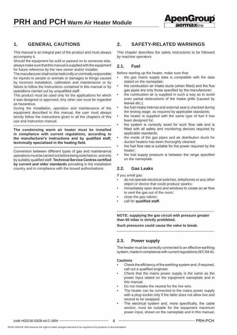
1. GENERAL CAUTIONS
This manual is an integral part of the product and must always accompany it. Should the equipment be sold or passed on to someone else, always make sure that this manual is supplied with the equipment for future reference by the new owner and/or installer.The manufacturer shall not be held civilly or criminally responsible for injuries to people or animals or damages to things caused by incorrect installation, calibration and maintenance or by failure to follow the instructions contained in this manual or by operations carried out by unqualified staff.This product must be used only for the applications for which it was designed or approved. Any other use must be regarded as hazardous.During the installation, operation and maintenance of the equipment described in this manual, the user must always strictly follow the instructions given in all the chapters of this use and instruction manual.----------------------------------------------------------------------------------The condensing warm air heater must be installed in compliance with current regulations, according to the manufacturer's instructions and by qualified staff, technically specialised in the heating field.----------------------------------------------------------------------------------Conversion between different types of gas and maintenance operations must be carried out before being switched on, and only by suitably qualified staff. Technical Service Centres certified by current and older standards prevailing in the installation country and in compliance with the issued authorisations.
2. SAFETY-RELATED WARNINGS
This chapter describes the safety instructions to be followed by machine operators
2.1. Fuel
Before starting up the heater, make sure that:• the gas mains supply data is compatible with the data
stated on the nameplate;• the combustion air intake ducts (when fitted) and the flue
gas pipes are only those specified by the manufacturer;• the combustion air is supplied in such a way as to avoid
even partial obstructions of the intake grille (caused by leaves etc.);
• the fuel intake internal and external seal is checked during the testing stage, as required by applicable standards;
• the heater is supplied with the same type of fuel it has been designed for;
• the system is correctly sized for such flow rate and is fitted with all safety and monitoring devices required by applicable standards;
• the inside of the gas pipes and air distribution ducts for ducted heaters has been thoroughly cleaned;
• the fuel flow rate is suitable for the power required by the heater;
• the fuel supply pressure is between the range specified on the nameplate.
2.2. Gas Leaks
If you smell gas:• do not operate electrical switches, telephones or any other
object or device that could produce sparks;• immediately open doors and windows to create an air flow
to vent the gas out of the room;• close the gas valves;• call for qualified staff.
------------------------------------------------------------------------- NOTE: supplying the gas circuit with pressure greater than 60 mbar is strictly prohibited.
Such pressures could cause the valve to break.
-------------------------------------------------------------------------
2.3. Power supply
The heater must be correctly connected to an effective earthing system, made in compliance with current regulations (IEC 64-8).
Cautions• Check the efficiency of the earthing system and, if required,
call out a qualified engineer.• Check that the mains power supply is the same as the
power input stated on the equipment nameplate and in this manual.
• Do not mistake the neutral for the live wire.• The heater can be connected to the mains power supply
with a plug-socket only if the latter does not allow live and neutral to be swapped.
• The electrical system and, more specifically, the cable section, must be suitable for the equipment maximum power input, shown on the nameplate and in this manual.

APEN GROUP SPA reserves the right to make changes deemed to be required to its products or documentation
4code HG0130.03GB ed.C-1804 PRH-PCH 5 code HG0130.03GB ed.C-1804PRH-PCH
PRH and PCH Warm Air Heater Module
HG0030 IM 001
Do not pull electric cables and keep them away from heat sources.---------------------------------------------------------------------------------NOTE: It is compulsory to install, upstream of the power cable, a fused multi-pole switch with contact opening wider than 3mm.The switch must be visible, accessible and less than 3m away from the control board.All electrical operations (installation and maintenance) must be carried out by qualified staff.---------------------------------------------------------------------------------
2.4. Use
Do not allow children or inexperienced people to use any electrically powered equipment.The following instructions must be followed:• do not touch the equipment with wet or damp parts of your
body and/or with bare feet;• do not leave the equipment exposed to the elements (rain,
sun etc...) unless it is adequately protected;• do not use the gas pipes to earth electrical equipment;• do not touch the hot parts of the heater, such as the flue
gas duct;• do not wet the heater with water or other fluids;• do not place any object over the equipment;• do not touch the moving parts of the heater.
2.5. Maintenance
---------------------------------------------------------------------------------Maintenance operations and combustion inspections must be carried out in compliance with current standards.---------------------------------------------------------------------------------Before carrying out any cleaning and maintenance operations, isolate the unit from the mains power supply using the switch located on the electrical system and/or on the shut-off devices.If the heater is faulty and/or incorrectly operating, switch it off and do not attempt to repair it yourself, but contact our local Technical Service Centre. All repairs must be carried out by using genuine spare parts. Failure to comply with the above instructions could compromise the safety of the equipment and invalidate the warranty.If the equipment is not used for long periods, shut the gas supply off through the gas stopcock and disconnect it from the power supply.If the heater is to be put out of service, in addition to the above operations, potential sources of hazard on the unit must be disabled.It is strictly forbidden to obstruct the Venturi pipe inlet, located on the burner-fan unit, with your hands or with any other objects. Any obstruction could cause a backfire from the premixed burner.
2.6. Transport and Handling
The heater is delivered fastened to a pallet and covered with a suitably secured cardboard box.Unload the heater from the truck and move it to the site of installation by using means of transport suitable for the shape of the load and for the weight.If the unit is stored at the customer’s premises, make sure a suitable place is selected, sheltered from rain and from excessive
humidity, for the shortest possible time.Any lifting and transport operations must be carried out by skilled staff, adequately trained and informed on the working procedures and safety regulations.Once the equipment is moved to the correct position, the unpacking operation can be started.The unpacking operation must be carried out by using suitable tools or safety devices where required.Recovered packaging materials must be separated and disposed of according to applicable regulations in the country of use.While unpacking the unit, check that the unit and all its parts have not been damaged during transport and match the order.If damages have occurred or parts are found to be missing, immediately contact the supplier.The manufacturer is not liable for any damages occurred during transport, handling or unloading.
2.7. Installation
The PRH and PCH heat exchanger must be used in the following conditions:The fuel used must have a sulphur content according to the European standard, namely: maximum peak, for short periods, 150 mg/m3, annual average lower than 30 mg/m3;• Combustion air must not contain chlorine, ammonia or alkalis; installation near swimming pools or laundries exposes the boiler to the effects of such agents.
DO NOT COVER IT WITH YOUR HAND OR OTHER OBJECTS!

PRH and PCH Warm Air Heater Module
APEN GROUP SPA reserves the right to make changes deemed to be required to its products or documentation
6code HG0130.03GB ed.C-1804 PRH-PCH 7 code HG0130.03GB ed.C-1804PRH-PCH
HG0130.00 A 002
3. TECHNICAL FEATURES
The PRH two-stage series and the PCH modulating condensing series warm air heaters have been designed to be built into air handling units and process dryers as heating units.
The premixing and modulating technology allows the heater to achieve efficiency of up to 109% of the L.C.V. (lower calorific value). The unit can be used on all machines requiring air to be heated during their operation (such as dryers, ventilation systems etc.).
The unit can operate independently. To start up the unit, simply connect it to the mains power supply and to the gas mains.
The unit thermal power output ranges from 5 to 97 kW. For greater output levels, multiple PRH/PCH heaters must be combined. They can be assembled in parallel to reach great heat output (up to 400 kW).
The units can be controlled in three ways:• proportionally, with a 0-10 Vdc external control;• with ON-OFF control;• with cascaded operation, when more units are installed.
The PRH/PCH module can be installed with the front panel supplied as an accessory, positioned directly on the outside, with no additional guard.The air is heated through its passage on combustion chamber and exchanger pipe surfaces.
The heat exchanger complies with construction requirements set by standard EN1196 for equipment where combustion gases produce condensate.
The combustion chamber and the surfaces in contact with condensation (such as the pipe bundle and exhaust hood), are made of AISI 441, in order to provide high resistance to condensation. The following table shows the conversion of stainless steels used:USA-AIS EN-No. COMPOSITIONAISI 430 1.4016 X6 Cr17AISI 441 1.4509 X2 CrTiNb 18
The innovative design and large surface of the combustion chamber and heat exchanger pipes ensure optimum efficiency and durability.The burner is made entirely of stainless steel with special mechanical solutions to ensure optimal reliability and performance levels, as well as high thermal and mechanical resistance.The control located inside the burner housing allows the service centre to check and view the working phases and identify any faults that may have occurred.
The PCH heater has a modulating mode of operation; the thermal output and, therefore, the heat output (fuel consumption) vary according to the heat demand. When the heat demand from the environment reduces, the heater uses less gas and increases its efficiency - up to 109% (a Net caloric value).
Inherent SafetyThe efficiency increase at minimum power is achieved by using a sophisticated air/gas mixing technique and by regulating at the same time the combustion air flow and the fuel gas flow.This technology increases the heater safety as the gas valve supplies the fuel according to the air flow. Unlike atmospheric burners, the CO2 content remains constant throughout the heater operating range, allowing the heater to increase its efficiency when the heat output reduces.If there is no combustion air, the valve will not supply gas; if the combustion air flow reduces, the valve will automatically reduce the gas flow yet will keep its combustion parameters at optimal levels.
Low emissionsThe premixed burner, in combination with the air/gas valve, ensures "clean" efficient combustion having low emissions.
Electrical control panel
Example of installation of a PRH/PCH heater with door
PCH series display

APEN GROUP SPA reserves the right to make changes deemed to be required to its products or documentation
6code HG0130.03GB ed.C-1804 PRH-PCH 7 code HG0130.03GB ed.C-1804PRH-PCH
PRH and PCH Warm Air Heater Module
Model PRH015 PRH024 PRH034 PRH042 PRH052 PRH072 PRH102
Type of equipment B23P - B53P - C13 - C43 - C53 - C63 - C83
CE approval PIN. 0476CQ0451
NOx class [EN1020:2009] Val 5 4
Heater Performance
min max min max min max min max min max min max min max
Burner heat output (Hi) kW 13.0 16.5 21.8 27.0 27.5 34.8 35.5 44.0 42.4 52.2 60 73.5 81.8 100.0
Useful Heat Output [Pmin, Prated]* kW 12.1 15.0 20.4 24.6 25.8 31.9 33.1 40.2 39.6 47.9 56.2 67.5 76.8 92.3
Hi Efficiency (N.C.V.) [ƞpl, ƞnom]* % 93.2 90.7 93.7 91.2 93.7 91.8 93.2 91.3 93.2 91.3 93.7 91.8 93.9 92.3
Hs efficiency (G.C.V.) [ƞpl, ƞnom]* % 83.8 81.6 84.3 81.2 84.3 82.6 83.8 82.2 84.7 83.0 84.3 82.6 84.5 83.1
Flue losses with burner on (Hi) % 6.8 9.3 6.3 8.8 6.3 8.2 6.8 8.7 6.6 8.2 6.3 8.2 6.1 7.7
Flue losses with burner off (Hi) % <0.1 <0.1 <0.1 <0.1 <0.1 <0.1 <0.1
Envelope loss factor [Fenv]* (1) % 0% 0% 0% 0% 0% 0% 0%
Seasonal space heating energy efficiency [Reg.EU/2281/2016] [ƞs,h]*
% 73,6 72,9 72,3 72,5 72,2 73,4 72,4
Emission efficiency [Reg.EU/2281/2016] [ƞsflow]* % 93,8 91,2 91,3 92,0 90,7 92,6 91,1
Flue gas emissions
Carbon monoxide - CO - (0% of O2) (2) ppm <5 <5 <5 <5 <5 <5 <5
Emissions of nitrogen oxides - NOx*(0% of O2) (Hi) (3)
44 mg/kWh - 25 ppm
30 mg/kWh - 17 ppm
30 mg/kWh - 17 ppm
44 mg/kWh - 25 ppm
44 mg/kWh - 25 ppm
43 mg/kWh - 24 ppm
58 mg/kWh - 33 ppm
Emissions of nitrogen oxides - NOx*(0% of O2) (Hs) (4)
40 mg/kWh - 22 ppm
27 mg/kWh - 15 ppm
27 mg/kWh - 15 ppm
40 mg/kWh - 22 ppm
42 mg/kWh - 24 ppm
39 mg/kWh - 23 ppm
52 mg/kWh - 30 ppm
Pressure available at the flue Pa 80 100 120 120 130 140 140
Flue gas temperature, CO2 content and flue gas mass flow rate: see gas tables on page 50 and on the following pages
Electrical Characteristics
Supply voltage V 230 Vac - 50 Hz single-phase
Rated electricity consumption [elmin - elmax ]* kW 0.037 0.063 0.033 0.058 0.045 0.074 0.037 0.071 0.056 0.101 0.061 0.112 0.080 0.121
Power input in stand-by [elsb]* kW 0.005
Protection Rating IP IP X5D
Operating Temperatures °C from -15°C to +40°C - for lower temperatures, a burner housing heating kit is required
Connections
Ø gas connection UNI/ISO 228/1-G 3/4"
UNI/ISO 228/1-G 3/4"
UNI/ISO 228/1-G 3/4"
UNI/ISO 228/1-G 3/4"
UNI/ISO 228/1-G 3/4"
UNI/ISO 228/1-G 3/4"
UNI/ISO 228/1- G 3/4 ''
Intake/exhaust pipes Ø mm 80/80 80/80 80/80 80/80 80/80 80/80 80/80
Air flow rate
Air flow rate (15° C)(5) m3/h 2000 2700 3100 4300 4500 7800 9000
Minimum air flow rate (6) m3/h 1300 2120 2750 3480 4140 5880 7960
Maximum air flow rate m3/h See diagram "Air flow rates - pressure drops"
Heat exchanger pressure drop Pa See diagram "Air flow rates - pressure drops"
Max. applicable pressure Pa 1200 1200 1200 1200 1200 1200 1200
Weight
Net Weight kg 39 39 48 48 58 72 98
3.1. Technical Data
There are 3 configurations of PRH/PCH, listed below:• A Single module (A System);• B Horizontally combined modules (B System);• C Vertically combined modules (C System).
A - PRH single modules (A System)They consist of a single heat exchanger; the range includes six models, i.e.: PRH 015, 024, 034, 042, 052, 072 and 102. The heat output ranges from 12.1 to 92.3 kW produced.The modules can be installed both horizontally and vertically, according to the air flow direction, regardless of the heater positioning.
NOTES:* Symbol of conformity with Reg.EU/2281/2016.(1) The losses from the enclosure must be regarded as zero as the machine is installed in an air handling/roof top unit.(2) Value referred to cat. H (G20).(3) Weighted value to EN1020:2009 ref. to cat. H (G20), referred to net calorific value (Hi, N.C.V).(4) Weighted value to EN1020:2009 ref. to cat. H (G20), referred to gross calorific value (Hs, G.C.V).(5) Reference air flow rate for the calculation of yields and season energy efficiencies and emissions listed in the table(6) The minimum air flow rate has been calculated for a ∆ of 35°C. For process systems or special applications using a ∆t > 40°C, please contact Apen Group.(7) Max. condensation produced acquired from testing at 30%Qn.

PRH and PCH Warm Air Heater Module
APEN GROUP SPA reserves the right to make changes deemed to be required to its products or documentation
8code HG0130.03GB ed.C-1804 PRH-PCH 9 code HG0130.03GB ed.C-1804PRH-PCH
Model PCH020 PCH034 PCH045 PCH065 PCH080 PCH105
Type of equipment B23P - B53P - C13 - C43 - C53 - C63 - C83
CE approval PIN. 0476CQ0451
NOx class [EN1020:2009] Val 5
Heater Performance
min max min max min max min max min max min max
Burner heat output (Hi) kW 4.75 19.00 7.60 34.85 8.50 42.00 12.40 65.00 16.40 82.00 21.00 100.00
Useful Heat Output [Pmin, Prated]* kW 4.97 18.18 8.13 33.56 8.97 40.45 13.40 62.93 17.77 80.03 22.77 97.15
Hi Efficiency (N.C.V.) [ƞpl, ƞnom]* % 104.63 95.68 106.97 96.30 105.50 96.30 108.06 96.82 108.35 97.60 108.40 97.15
Hs efficiency (G.C.V.) [ƞpl, ƞnom]* % 94.26 86.20 96.37 86.76 95.07 86.76 97.36 87.22 97.62 87.93 97.68 87.52
Flue losses with burner on (Hi) % 0.4 4.3 0.6 3.7 0.5 3.7 0.2 3.2 0.3 2.4 0.2 2.8
Flue losses with burner off (Hi) % <0.1 <0.1 <0.1 <0.1 <0.1 <0.1
Envelope loss factor [Fenv]* (1) % 0% 0% 0% 0% 0% 0%
Seasonal space heating energy efficiency [Reg.EU/2281/2016] [ƞs,h]*
% 90.5 92.1 90.8 93.2 93.2 93.1
Emission efficiency [Reg.EU/2281/2016] [ƞsflow]* % 97.5 97.3 97.0 97.4 97.1 97.0
Max. condensation (7) l/h 0.4 0.9 1.1 2.1 3.3 2.7
Flue gas emissions
Carbon monoxide - CO - (0% of O2) (2) ppm < 5 < 5 < 5 < 5 < 5 < 5
Emissions of nitrogen oxides - NOx*(0% of O2) (Hi) (3)
38 mg/kWh - 22 ppm
42 mg/kWh - 24 ppm
33 mg/kWh - 19 ppm
39 mg/kWh - 22 ppm
41 mg/kWh - 23 ppm
39 mg/kWh - 22 ppm
Emissions of nitrogen oxides - NOx*(0% of O2) (Hs) (4)
34 mg/kWh - 20 ppm
38 mg/kWh - 22 ppm
30 mg/kWh - 17 ppm
35 mg/kWh - 20 ppm
37 mg/kWh - 21 ppm
35 mg/kWh - 20 ppm
Pressure available at the flue Pa 80 90 100 120 120 120
Flue gas temperature, CO2 content and flue gas mass flow rate: see gas tables on page 50 and on the following pages
Electrical Characteristics
Supply voltage V 230 Vac - 50 Hz single-phase
Rated electricity consumption [elmin - elmax ]* kW 0.011 0.045 0.011 0.074 0.024 0.082 0.015 0.097 0.020 0.123 0.020 0.130
Power input in stand-by [elsb]* kW 0.005
Protection Rating IP IP X5D
Operating Temperatures °C from -15°C to +40°C - for lower temperatures, a burner housing heating kit is required
Connections
Ø gas connectionUNI/ISO 228/1-
G 3/4"
UNI/ISO 228/1- G 3/4"
UNI/ISO 228/1- G 3/4"
UNI/ISO 228/1- G 3/4"
UNI/ISO 228/1- G 3/4"
UNI/ISO 228/1- G 3/4"
Intake/exhaust pipes Ø mm 80/80 80/80 80/80 80/80 80/80 80/80
Air flow rate
Air flow rate (15° C)(5) m3/h 2700 4300 4500 7800 9000 11100
Minimum air flow rate (6) m3/h 1490 2750 3330 5160 6560 7960
Maximum air flow rate m3/h See diagram "Air flow rates - pressure drops"
Heat exchanger pressure drop Pa See diagram "Air flow rates - pressure drops"
Max. applicable pressure Pa 1200 1200 1200 1200 1200 1200
Weight
Net Weight kg 39 48 58 72 98 118
A - PCH single modules (A System)They consist of a single heat exchanger; the range includes six models, i.e.: PCH020, 034, 045, 065, 080 and 105. The heat output ranges from 5 to 97.2 kW produced.The modules can be installed both horizontally and vertically, according to the air flow direction. If the installation requires a vertical air flow, the customer must ask APEN GROUP to provide a PCH heater with a code ending with -00V0 (for more information, see paragraph 4.4 Installing single or multiple modules).
APEN GROUP SPA reserves the right to make changes deemed to be required to its products or documentation
8code HG0130.03GB ed.C-1804 PRH-PCH 9 code HG0130.03GB ed.C-1804PRH-PCH
PRH and PCH Warm Air Heater Module
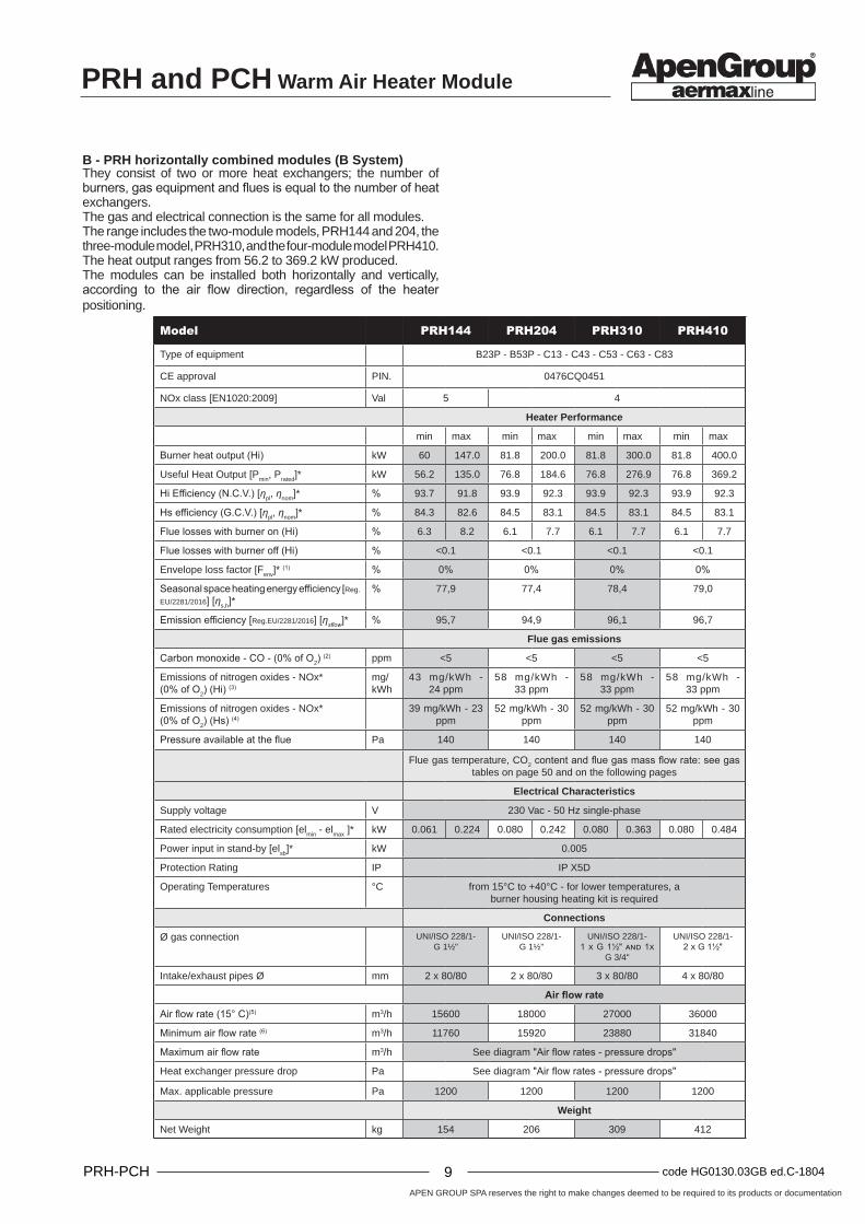
Model PRH144 PRH204 PRH310 PRH410
Type of equipment B23P - B53P - C13 - C43 - C53 - C63 - C83
CE approval PIN. 0476CQ0451
NOx class [EN1020:2009] Val 5 4
Heater Performance
min max min max min max min max
Burner heat output (Hi) kW 60 147.0 81.8 200.0 81.8 300.0 81.8 400.0
Useful Heat Output [Pmin, Prated]* kW 56.2 135.0 76.8 184.6 76.8 276.9 76.8 369.2
Hi Efficiency (N.C.V.) [ƞpl, ƞnom]* % 93.7 91.8 93.9 92.3 93.9 92.3 93.9 92.3
Hs efficiency (G.C.V.) [ƞpl, ƞnom]* % 84.3 82.6 84.5 83.1 84.5 83.1 84.5 83.1
Flue losses with burner on (Hi) % 6.3 8.2 6.1 7.7 6.1 7.7 6.1 7.7
Flue losses with burner off (Hi) % <0.1 <0.1 <0.1 <0.1
Envelope loss factor [Fenv]* (1) % 0% 0% 0% 0%
Seasonal space heating energy efficiency [Reg.
EU/2281/2016] [ƞs,h]*% 77,9 77,4 78,4 79,0
Emission efficiency [Reg.EU/2281/2016] [ƞsflow]* % 95,7 94,9 96,1 96,7
Flue gas emissions
Carbon monoxide - CO - (0% of O2) (2) ppm <5 <5 <5 <5
Emissions of nitrogen oxides - NOx*(0% of O2) (Hi) (3)
mg/kWh
43 mg/kWh - 24 ppm
58 mg/kWh - 33 ppm
58 mg/kWh - 33 ppm
58 mg/kWh - 33 ppm
Emissions of nitrogen oxides - NOx*(0% of O2) (Hs) (4)
39 mg/kWh - 23 ppm
52 mg/kWh - 30 ppm
52 mg/kWh - 30 ppm
52 mg/kWh - 30 ppm
Pressure available at the flue Pa 140 140 140 140
Flue gas temperature, CO2 content and flue gas mass flow rate: see gas tables on page 50 and on the following pages
Electrical Characteristics
Supply voltage V 230 Vac - 50 Hz single-phase
Rated electricity consumption [elmin - elmax ]* kW 0.061 0.224 0.080 0.242 0.080 0.363 0.080 0.484
Power input in stand-by [elsb]* kW 0.005
Protection Rating IP IP X5D
Operating Temperatures °C from 15°C to +40°C - for lower temperatures, a burner housing heating kit is required
Connections
Ø gas connection UNI/ISO 228/1- G 1½"
UNI/ISO 228/1- G 1½"
UNI/ISO 228/1- 1 x G 1½" and 1x
G 3/4"
UNI/ISO 228/1- 2 x G 1½"
Intake/exhaust pipes Ø mm 2 x 80/80 2 x 80/80 3 x 80/80 4 x 80/80
Air flow rate
Air flow rate (15° C)(5) m3/h 15600 18000 27000 36000
Minimum air flow rate (6) m3/h 11760 15920 23880 31840
Maximum air flow rate m3/h See diagram "Air flow rates - pressure drops"
Heat exchanger pressure drop Pa See diagram "Air flow rates - pressure drops"
Max. applicable pressure Pa 1200 1200 1200 1200
Weight
Net Weight kg 154 206 309 412
B - PRH horizontally combined modules (B System)They consist of two or more heat exchangers; the number of burners, gas equipment and flues is equal to the number of heat exchangers.The gas and electrical connection is the same for all modules.The range includes the two-module models, PRH144 and 204, the three-module model, PRH310, and the four-module model PRH410.The heat output ranges from 56.2 to 369.2 kW produced.The modules can be installed both horizontally and vertically, according to the air flow direction, regardless of the heater positioning.

PRH and PCH Warm Air Heater Module
APEN GROUP SPA reserves the right to make changes deemed to be required to its products or documentation
10code HG0130.03GB ed.C-1804 PRH-PCH 11 code HG0130.03GB ed.C-1804PRH-PCH
Model PCH130 PCH160 PCH210 PCH320 PCH420
Type of equipment B23P - B53P - C13 - C43 - C53 - C63 - C83
CE approval PIN. 0476CQ0451
NOx class [EN1020:2009] Val 5
Heater Performance
min max min max min max min max min max
Burner heat output (Hi) kW 12.40 130.00 16.40 164.00 21.00 200.00 21.00 300.00 21.00 400.00
Useful Heat Output [Pmin, Prated]* kW 13.40 125.86 17.77 160.06 22.77 194.30 22.77 291.45 22.77 388.60
Hi Efficiency (N.C.V.) [ƞpl, ƞnom]* % 108.06 96.82 108.35 97.60 108.40 97.15 108.40 97.15 108.40 97.15
Hs efficiency (G.C.V.) [ƞpl, ƞnom]* % 97.36 87.22 97.62 87.93 97.68 87.52 97.68 87.52 97.68 87.52
Flue losses with burner on (Hi) % 0.2 3.2 0.3 2.4 0.2 2.8 0.2 2.8 0.2 2.8
Flue losses with burner off (Hi) % <0.1 <0.1 <0.1 <0.1 <0.1
Envelope loss factor [Fenv]* (1) % 0% 0% 0% 0% 0%
Seasonal space heating energy efficiency [Reg.EU/2281/2016] [ƞs,h]*
% 93.9 94.0 94.0 94.2 94.4
Emission efficiency [Reg.EU/2281/2016] [ƞsflow]* % 98.1 97.9 97.9 98.1 98.3
Max. condensation (7) l/h 4.2 6.6 5.4 8.1 10.8
Flue gas emissions
Carbon monoxide - CO - (0% of O2) (2) ppm < 5 < 5 < 5 < 5 < 5
Emissions of nitrogen oxides - NOx*(0% of O2) (Hi) (3)
39 mg/kWh - 22 ppm
41 mg/kWh - 23 ppm
39 mg/kWh - 22 ppm
39 mg/kWh - 22 ppm
39 mg/kWh - 22 ppm
Emissions of nitrogen oxides - NOx*(0% of O2) (Hs) (4)
35 mg/kWh - 20 ppm
37 mg/kWh - 21 ppm
35 mg/kWh - 20 ppm
35 mg/kWh - 20 ppm
35 mg/kWh - 20 ppm
Pressure available at the flue Pa 120 120 120 120 120
Flue gas temperature, CO2 content and flue gas mass flow rate: see gas tables on page 50 and on the following pages
Electrical Characteristics
Supply voltage V 230 Vac - 50 Hz single-phase
Rated electricity consumption [elmin - elmax ]* kW 0.015 0.194 0.020 0.246 0.020 0.260 0.020 0.390 0.020 0.520
Power input in stand-by [elsb]* kW 0.005
Protection Rating IP IP X5D
Operating Temperatures °C from 15°C to +40°C - for lower temperatures, a burner housing heating kit is required
Connections
Ø gas connection UNI/ISO 228/1- G 1½"
UNI/ISO 228/1- G 1½"
UNI/ISO 228/1- G 1½"
UNI/ISO 228/1- 1 x G 1½" e 1 x G 3/4"
UNI/ISO 228/1- 2 x G 1½"
Intake/exhaust pipes Ø mm 2 x 80/80 2 x 80/80 2 x 80/80 3 x 80/80 4 x 80/80
Air flow rate
Air flow rate (15° C)(5) m3/h 15600 18000 22200 33300 44400
Minimum air flow rate (6) m3/h 10320 13120 15920 23880 31840
Maximum air flow rate m3/h See diagram "Air flow rates - pressure drops"
Heat exchanger pressure drop Pa See diagram "Air flow rates - pressure drops"
Max. applicable pressure Pa 1200 1200 1200 1200 1200
Weight
Net Weight kg 154 206 250 375 500
B - PCH Horizontally combined modules (B System)They consist of two or more heat exchangers; the number of burners, gas equipment and flues is equal to the number of heat exchangers.The gas and electrical connection is the same for all modules.The range includes two module models, PCH130, 160 and 210, the three module model, PCH320, and four module model PCH420.The heat output ranges from 13.4 to 388.8 kW produced.
Module operation is cascaded by means of 0/10 Vdc signal and/or ON/OFF signal taken to the single module.The modules can be installed both horizontally and vertically, according to the air flow direction, regardless of the heater positioning. If the installation requires a vertical air flow, the customer must ask APEN GROUP to provide a PCH heater with a code ending with -00V0 (for more information, see paragraph 4.4 Installing single or multiple modules).

APEN GROUP SPA reserves the right to make changes deemed to be required to its products or documentation
10code HG0130.03GB ed.C-1804 PRH-PCH 11 code HG0130.03GB ed.C-1804PRH-PCH
PRH and PCH Warm Air Heater Module
Model PRH152 PRH202
Type of equipment B23P - B53P - C13 - C43 - C53 - C63 - C83
CE approval PIN. 0476CQ0451
NOx class [EN1020:2009] Val 5 4
Heater Performance
min max min max
Burner heat output (Hi) kW 60 147.0 81.8 200.0
Useful Heat Output [Pmin, Prated]* kW 56.2 135.0 76.8 184.6
Hi Efficiency (N.C.V.) [ƞpl, ƞnom]* % 93.7 91.8 93.9 92.3
Hs efficiency (G.C.V.) [ƞpl, ƞnom]* % 84.3 82.6 84.5 83.1
Flue losses with burner on (Hi) % 6.3 8.2 6.1 7.7
Flue losses with burner off (Hi) % <0.1 <0.1
Envelope loss factor [Fenv]* (1) % 0% 0%
Seasonal space heating energy efficiency [Reg.EU/2281/2016] [ƞs,h]*
% 77,9 77,4
Emission efficiency [Reg.EU/2281/2016] [ƞsflow]* % 95,7 94,9
Flue gas -Polluting emissions
Carbon monoxide - CO - (0% of O2) (2) ppm <5 <5
Emissions of nitrogen oxides - NOx*(0% of O2) (Hi) (3)
mg/kWh
4 3 m g / k W h - 24 ppm
5 8 m g / k W h - 33 ppm
Emissions of nitrogen oxides - NOx*(0% of O2) (Hs) (4)
39 mg/kWh - 23 ppm 52 mg/kWh - 30 ppm
Pressure available at the flue Pa 140 140
Flue gas temperature, CO2 content and flue gas mass flow rate: see gas tables on page 50 and
on the following pages
Electrical Characteristics
Supply voltage V 230 Vac - 50 Hz single-phase
Rated electricity consumption [elmin - elmax ]* kW 0.061 0.224 0.080 0.242
Power input in stand-by [elsb]* kW 0.005
Protection Rating IP IP X5D
Operating Temperatures °C from -15°C to +40°C - for lower temperatures, a burner housing heating kit is required
Connections
Ø gas connection UNI/ISO 228/1- G 1½"
UNI/ISO 228/1- G 1½"
Intake/exhaust pipes Ø mm 2 x 80/80 2 x 80/80
Air flow rate
Air flow rate (15° C)(5) m3/h 15600 18000
Minimum air flow rate (6) m3/h 11760 15920
Maximum air flow rate m3/h See diagram "Air flow rates - pressure drops"
Heat exchanger pressure drop Pa See diagram "Air flow rates - pressure drops"
Max. applicable pressure Pa 1200 1200
Weight
Net Weight kg 148 200
C- PRH Vertically combined modules (C System)They consist of two heat exchangers; the number of burners, gas equipment and flues is equal to the number of heat exchangers.The gas and electrical connection is the same for all modules.These modules have a reduced width and low pressure drops when air goes through.The range includes two-module models PRH152 and 202.The heat output ranges from 56.2 to 184.6 kW produced.
The modules can be installed with horizontal air flow direction only. Heaters with vertical air flow cannot be installed.

PRH and PCH Warm Air Heater Module
APEN GROUP SPA reserves the right to make changes deemed to be required to its products or documentation
12code HG0130.03GB ed.C-1804 PRH-PCH 13 code HG0130.03GB ed.C-1804PRH-PCH
Model PCH132 PCH162 PCH212
Type of equipment B23P - B53P - C13 - C43 - C53 - C63 - C83
CE approval PIN. 0476CQ0451
NOx class [EN1020:2009] Val 5
Heater Performance
min max min max min max
Burner heat output (Hi) kW 12.40 130.00 16.40 164.00 21.00 200.00
Useful Heat Output [Pmin, Prated]* kW 13.40 125.86 17.77 160.06 22.77 194.30
Hi Efficiency (N.C.V.) [ƞpl, ƞnom]* % 108.06 96.82 108.35 97.60 108.40 97.15
Hs efficiency (G.C.V.) [ƞpl, ƞnom]* % 97.36 87.22 97.62 87.93 97.68 87.52
Flue losses with burner on (Hi) % 0.2 3.2 0.3 2.4 0.2 2.8
Flue losses with burner off (Hi) % <0.1 <0.1 <0.1
Envelope loss factor [Fenv]* (1) % 0% 0% 0%
Seasonal space heating energy efficiency [Reg.EU/2281/2016] [ƞs,h]*
% 93.9 94.0 94.0
Emission efficiency [Reg.EU/2281/2016] [ƞsflow]* % 98.1 97.9 97.9
Max. condensation (7) l/h 4.2 6.6 5.4
Flue gas emissions
Carbon monoxide - CO - (0% of O2) (2) ppm < 5 < 5 < 5
Emissions of nitrogen oxides - NOx*(0% of O2) (Hi) (3)
39 mg/kWh - 22 ppm
41 mg/kWh - 23 ppm
39 mg/kWh - 22 ppm
Emissions of nitrogen oxides - NOx*(0% of O2) (Hs) (4)
35 mg/kWh - 20 ppm
37 mg/kWh - 21 ppm
35 mg/kWh - 20 ppm
Pressure available at the flue Pa 120 120 120
Flue gas temperature, CO2 content and flue gas mass flow rate: see gas tables on page 50 and on the following pages
Electrical Characteristics
Supply voltage V 230 Vac - 50 Hz single-phase
Rated electricity consumption [elmin - elmax ]* kW 0.015 0.194 0.020 0.246 0.020 0.260
Power input in stand-by [elsb]* kW 0.005
Protection Rating IP IP X5D
Operating Temperatures °C from -15°C to +40°C - for lower temperatures, a burner housing heating kit is required
Connections
Ø gas connection UNI/ISO 228/1- G 1½"
UNI/ISO 228/1- G 1½"
UNI/ISO 228/1- G 1½"
Intake/exhaust pipes Ø mm 2 x 80/80 2 x 80/80 2 x 80/80
Air flow rate
Air flow rate (15° C)(5) m3/h 15600 18000 22200
Minimum air flow rate (6) m3/h 10320 13120 15920
Maximum air flow rate m3/h See diagram "Air flow rates - pressure drops"
Heat exchanger pressure drop Pa See diagram "Air flow rates - pressure drops"
Max. applicable pressure Pa 1200 1200 1200
Weight
Net Weight kg 148 200 240
C- PCH Vertically combined modules (C System)They consist of two heat exchangers; the number of burners, gas equipment and flues is equal to the number of heat exchangers.The gas and electrical connection is the same for all modules.These modules have a reduced width and low pressure drops when air goes through.The range includes two-module models, PCH132, 162 and 212.
The heat output ranges from 13.4 to 194.4 kW produced.Module operation is cascaded by means of 0/10 Vdc signal and/or ON/OFF signal taken to the single module.The modules can be installed with horizontal air flow direction only. Heaters with vertical air flow cannot be installed.

APEN GROUP SPA reserves the right to make changes deemed to be required to its products or documentation
12code HG0130.03GB ed.C-1804 PRH-PCH 13 code HG0130.03GB ed.C-1804PRH-PCH
PRH and PCH Warm Air Heater Module
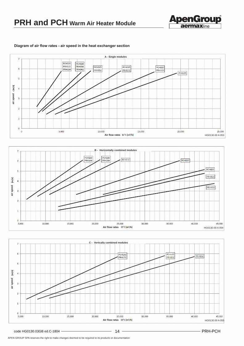
Air flow - pressure drop diagram
A - Single modules
B - Horizontally combined modules
C - Vertically combined modules
Air flow rate at 15°C [m3/h]
Air flow rate at 15°C [m3/h]
Air flow rate at 15°C [m3/h]
PRH and PCH Warm Air Heater Module
APEN GROUP SPA reserves the right to make changes deemed to be required to its products or documentation
14code HG0130.03GB ed.C-1804 PRH-PCH 15 code HG0130.03GB ed.C-1804PRH-PCH
HG0130.00 A 053
HG0130.00 A 054
HG0130.00 A 055Air flow rates
C - Vertically combined modules
Diagram of air flow rates - air speed in the heat exchanger section
air
spee
d
air
spee
d
air
spee
d
A - Single modules
Air flow rates
Air flow rates
B - Horizontally combined modules

APEN GROUP SPA reserves the right to make changes deemed to be required to its products or documentation
14code HG0130.03GB ed.C-1804 PRH-PCH 15 code HG0130.03GB ed.C-1804PRH-PCH
PRH and PCH Warm Air Heater Module
HG0130.00 A 003c
Mod.PCH
Overall dimensions
B H L H1 H2 H3 L1 L2 L3 E G* A S C*
PCH020
450
660710
534
63 -
450
230 472X
Ø21G
3/4'' Ø 80 Ø 80 G ½''
PCH034950 690
PCH045730 604
PCH065 1250 990
PCH080815
1440689
1180
PCH105 1670 1410
Mod. PRH
Overall dimensions
B H L H1 H2 H3 L1 L2 L3 E G* A S
PRH015PRH024
450
660710
534
63 -
450
230 472X
Ø21G
3/4'' Ø 80 Ø 80
PRH034PRH042 950 690PRH052
730 604PRH072 1250 990
PRH102 815 1440 689 1180
3.2. Dimensions
A - Single modules (A System)
KEY:E electrical connections;G gas connection;A intake;S flue gas drainage;C condensate drainage (for PCH models only);* reference ISO 228/1.

PRH and PCH Warm Air Heater Module
APEN GROUP SPA reserves the right to make changes deemed to be required to its products or documentation
16code HG0130.03GB ed.C-1804 PRH-PCH 17 code HG0130.03GB ed.C-1804PRH-PCH
HG0130.00 A 004c
Mod.PCH
Overall dimensions
B H L H1 H2 H3 L1 L2 L3 E G* A S C* D
PCH130 740
1050
1260
418 53 108
1000
230 472X
Ø21
G 1½''
2X Ø 80
2X Ø 80
1 X G ½''
Ø 21
PCH160
825
1450 1190
PCH210
1680 1420PCH320 1575
1XG 1½''
+ 1xG 3/4''
3X Ø 80
3X Ø 80
PCH420 21002XG 1½''
4X Ø 80
4X Ø 80
Mod.PRH
Overall dimensions
B H L H1 H2 H3 L1 L2 L3 E G* A S
PRH144 7401050
1260
418 53 108
1000
230 472X
Ø21
G 1½''
2X Ø 80
2X Ø 80PRH204
825 1450 1190PRH310 1575
1XG 1½''
+ 1xG 3/4''
3X Ø 80
3X Ø 80
PRH410 21002XG 1½''
4X Ø 80
4X Ø 80
B - Horizontally combined modules (B System)
KEY:E electrical connections;G gas connection;A intake;S flue gas drainage;C condensate drainage (for PCH models only);D condensate vent;* reference ISO 228/1.

APEN GROUP SPA reserves the right to make changes deemed to be required to its products or documentation
16code HG0130.03GB ed.C-1804 PRH-PCH 17 code HG0130.03GB ed.C-1804PRH-PCH
PRH and PCH Warm Air Heater Module
HG0130.00 A 005a
Mod.PCH
Overall dimensions
B H L H1 H2 H3 L1 L2 L3 E G* A S C* D
PCH132
450
1460 1250 604
63 126
990
230 472X
Ø21G
1 ½''2X Ø
802X Ø
801 X
G ½''Ø 18PCH162
16301440
6891180
PCH212 1670 1410
Mod.PRH
Overall dimensions
B H L H1 H2 H3 L1 L2 L3 E G* A S
PRH152
450
1460 1250 604
63 126
990
230 472X
Ø21G
1 ½''2X Ø
802X Ø
80PRH202 1630 1440 689 1180
C- Vertically combined modules (C System)
KEY:E electrical connections;G gas connection;A intake;S flue gas drainage;C condensate drainage (for PCH models only);D condensate vent;* reference ISO 228/1.
PRH and PCH Warm Air Heater Module
APEN GROUP SPA reserves the right to make changes deemed to be required to its products or documentation
18code HG0130.03GB ed.C-1804 PRH-PCH 19 code HG0130.03GB ed.C-1804PRH-PCH
HG0130.00 A 009
HG0130.00 A 007
HG0130.00 A 006
HG0130.00 A 008
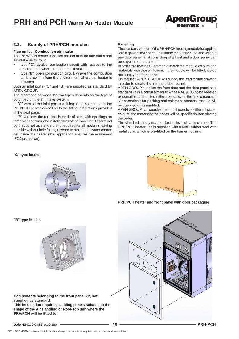
3.3. Supply of PRH/PCH modules
Flue outlet - Combustion air intakeThe PRH/PCH heater modules are certified for flue outlet and air intake as follows:• type "C": sealed combustion circuit with respect to the
environment where the heater is installed;• type "B": open combustion circuit, where the combustion
air is drawn in from the environment where the heater is installed.
Both air inlet ports ("C" and "B") are supplied as standard by APEN GROUP.The difference between the two types depends on the type of port fitted on the air intake system.In "C" version the inlet port is a fitting to be connected to the PRH/PCH heater according to the fitting instructions provided in the next page.In "B" versions the terminal is made of steel with openings on three sides and must be installed by slotting it over the "C" terminal port (supplied as standard and required for all models), leaving the side without hole facing upward to make sure water cannot get inside the heater (this application ensures the equipment IPX5 protection).
PanellingThe standard version of the PRH/PCH heating module is supplied with a galvanised sheet, unsuitable for outdoor use and without any door panel; a kit consisting of a front and a door panel can be supplied on request.In order to allow the Customer to match the module colours and materials with those into which the module will be fitted, we do not supply the front panel.On request, APEN GROUP will supply the .cad format drawing in order to create the front and door panel.APEN GROUP supplies the front door and the door panel as a standard kit in a colour similar to white RAL 9003, to be ordered by using the codes listed in the table shown in the next paragraph "Accessories"; for packing and shipment reasons, the kits will be supplied unassembled.APEN GROUP can supply on request panels of different sizes, colours and materials; the prices will be specified when placing the order. The standard supply includes fast locks and cable clamps. The PRH/PCH heater unit is supplied with a NBR rubber seal with metal core, which is pre-fitted on the burner housing.
"C" type intake
"B" type intake
Components belonging to the front panel kit, not supplied as standard. This installation requires cladding panels suitable to the shape of the Air Handling or Roof-Top unit where the PRH/PCH will be fitted to.
PRH/PCH heater and front panel with door packaging

APEN GROUP SPA reserves the right to make changes deemed to be required to its products or documentation
18code HG0130.03GB ed.C-1804 PRH-PCH 19 code HG0130.03GB ed.C-1804PRH-PCH
PRH and PCH Warm Air Heater Module
HG0130.00 A 010
ModelPCH
Front panel kit
Code
PCH020G28881
PCH034
PCH045G28882
PCH065
PCH080G28883
PCH105
PCH130 G28884
PCH160G28885
PCH210
PCH320 G28886
PCH420 G28887
PCH132 G28888
PCH162G28889
PCH212
ModelPRH
Front panel kit
Code
PRH015
G28881PRH024
PRH034
PRH042
PRH052G28882
PRH072
PRH102 G28883
PRH144 G28884
PRH204 G28885
PRH310 G28876
PRH410 G28877
PRH152 G28888
PRH202 G28889
AccessoriesThe front panel kit, as an accessory, must be ordered to APEN GROUP by using the following codes:
To assemble the unit, proceed as follows:• apply, along the perimeter of the PRH/PCH housing
galvanised panel, a silicone bead to make the PRH/PCH heater outer panel watertight, as shown in the figure (this application is compulsory to ensure IPX5 protection for the equipment);
• fix the front panel to the unit, using the M6 x 16 front screws;• secure the gas pipe to the front panel by using the seal
and the locknut;• fit the electrical cable clamps to the front or side panel,
according to the configuration of the machine;• fit the air intake fitting by inserting the black O-ring seal
between the front panel and the fitting; use the 8 self-tapping M4 x 16 screws;
• fit the locks on the door panel.
"B" type heater with combustion circuit open to the environment in which it is installedFit the accessories for the air intake and flue (see the picture on the next page) which must reach a suitable external location.
"C" type heater with combustion circuit sealed from the environment in which it is installedFit the combustion air inlet and the flue outlet accessories (see the picture on the next page) which must reach a suitable external location.
The front panel kit includes the closing panel and the door to be applied to the closing panel.
For installation in environments where the air temperature drops below -15°C, we recommend to request the housing heating kit:• G28560 for PRH models;• G28510 for PCH models.Kit installation, connection and adjustment modes inside the warm air heater module are described in the installation manual.
Standard supplyEach PRH/PCH heater is supplied with some accessories, essential to ensure correct installation:• 1 intake terminal;• 1 intake terminal for "B23" application;• 1 flue outlet terminal;• 2 black EPDM seals for flue;• 8 three-lobe M4 x 16 screws;• 6 M6 x 16 screws;• 6 washers;• 6 red silicone rubber seals;• 2 PG13.5 cable clamps;• 1 green klin/sil seal (for gas locknut);• 1 locknut for gas pipe;• 4 1/4 slotted head locks.
Fitting the front panel and the door
NBR rubber seal, supplied with PRH/PCH heater
Seal to be fitted on site with silicone.Follow the profile shown in the picture
PRH and PCH Warm Air Heater Module
APEN GROUP SPA reserves the right to make changes deemed to be required to its products or documentation
20code HG0130.03GB ed.C-1804 PRH-PCH 21 code HG0130.03GB ed.C-1804PRH-PCH
HG0130.00 A 013
HG0130.00 A 012
HG0130.00 A 011
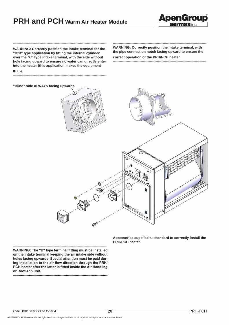
---------------------------------------------------------------------------------WARNING: The "B" type terminal fitting must be installed on the intake terminal keeping the air intake side without holes facing upwards. Special attention must be paid dur-ing installation to the air flow direction through the PRH/PCH heater after the latter is fitted inside the Air Handling or Roof-Top unit.------------------------------------------------------------------------------------
---------------------------------------------------------------------------------WARNING: Correctly position the intake terminal, with the pipe connection notch facing upward to ensure the
correct operation of the PRH/PCH heater.---------------------------------------------------------------------------------
Accessories supplied as standard to correctly install the PRH/PCH heater.
---------------------------------------------------------------------------------
WARNING: Correctly position the intake terminal for the "B23" type application by fitting the internal cylinder over the "C" type intake terminal, with the side without hole facing upward to ensure no water can directly enter into the heater (this application makes the equipment
IPX5).---------------------------------------------------------------------------------
"Blind" side ALWAYS facing upwards

APEN GROUP SPA reserves the right to make changes deemed to be required to its products or documentation
20code HG0130.03GB ed.C-1804 PRH-PCH 21 code HG0130.03GB ed.C-1804PRH-PCH
PRH and PCH Warm Air Heater Module
HG0130.00 A 014
HG0130.00 A 015
4. INSTALLATION INSTRUCTIONS
Instructions for installing and setting the heater are intended for suitably qualified personnel only. We recommend the installer to read safety warnings.Installation instructions for units including a PRH/PCH module are the same as those applying to air heater installation because, from the regulatory point of view, PRH/PCH modules are warm air generators.
4.1. Installing the module inside the units
The PRH/PCH module can be fitted to Air Handling or Roof Top units in two different ways:OUTDOOR installation: the module outer panel is outside the unit.INDOOR installation: the module outer panel is fitted inside the unit, creating a gap between the module and the outer panel of the unit.
OUTDOOR InstallationEither “C” type (sealed combustion chamber) and “B” type (open combustion chamber) can be used for the OUTDOOR installation. If the heater is installed outdoor, pay attention to correctly install the seal on the door; make sure preventive measures are taken to prevent water from entering the burner casing (see the picture showing the position of the seals in the previous pages).In order to install a “C” type module with watertight combustion chamber, connect an air intake pipe and associated terminal to the air port.If a “B” type installation is required (with open combustion chamber), fit to the air intake the stainless steel terminal supplied by APEN GROUP as standard.The OUTDOOR installation must be carried out by using the front panel kit (see paragraph 3.3 "Supply of PCH modules") or by fitting a special panel to be made in compliance with the drawings (in .cad format) that APEN GROUP can supply on request.
INDOOR InstallationBoth “C” type (sealed combustion chamber) and “B” type (open combustion chamber) can be used for the INDOOR installation.
"B" type heater with combustion circuit open to the environment in which it is installedIn this case further precautions must be taken in addition to those required to prevent water from entering the burner housing. For example, the compartment where the heater will be connected to the gas supply will need to be ventilated by making some vents on the outer panel equal to 2% of the larger internal section. These vents must be equally split between the top and the bottom of the panel (EN525) and the gap must be airtight with respect to the air treatment passage. For this type of heater, the combustion air can be drawn directly from the gap; therefore great care must be taken to completely seal the such gap, in particular in installations where the unit fan is located downstream of the PRH/PCH heater.---------------------------------------------------------------------------------NOTE: Under no circumstances should supply air be extracted from the compartment of the air handling unit or the roof-top unit by the supply-air fan as this would cause, when the burner is switched off, very hot air from the heat exchanger to pass through the burner, causing irreparable damages to the burner fan.----------------------------------------------------------------------------------
Outdoor installation example Indoor installation example (with gap vent opening)
PRH and PCH Warm Air Heater Module
APEN GROUP SPA reserves the right to make changes deemed to be required to its products or documentation
22code HG0130.03GB ed.C-1804 PRH-PCH 23 code HG0130.03GB ed.C-1804PRH-PCH
HG0130.00 A 017
HG0130.00 A 016
4.2. Installing the Module
In order to install a PRH/PCH module into an air handling or roof-top unit, we recommend to prepare four support guides similar to those shown in the adjacent picture, or to make sure that the heater, located inside the housing, is placed and locked safely in place to prevent its movement or damage during the transport.These guides/supports can also be totally or partially closed to reduce pressure drops, depending on air flow.With high air flow rates, in order to avoid great pressure drops, the system designer must provide the system with a bypass section. THIS section can be calculated by following the instructions provided in paragraph 4.3 "Bypass calculation" or by using a calculation software supplied on request by APEN GROUP.
Precautions to be taken for surrounding areasAn STB safety thermostat is fitted in the PRH/PCH heater, together with a temperature control probe, installed in the heat exchanger centreline.The thermostat may be accessed from the outside through the burner housing during maintenance and/or replacement operations.
All components belonging to the air handling unit or the roof-top unit where the PRH/PCH heater will be located (fans, filters, drop separators etc.),• if made of plastic, they must be installed at a distance of
least 1 m, with an access grille between them ----------------------------------------------------------------------------------NOTE: The plastic used must be of V0 UL94 type (flame retardant)--------------------------------------------------------------------------------• if made of metal, they must be fitted at a distance of at least
500 mm without grille.The distance is required to protect the filter in the event of a power failure, and therefore ventilation when the heat exchanger is hot.
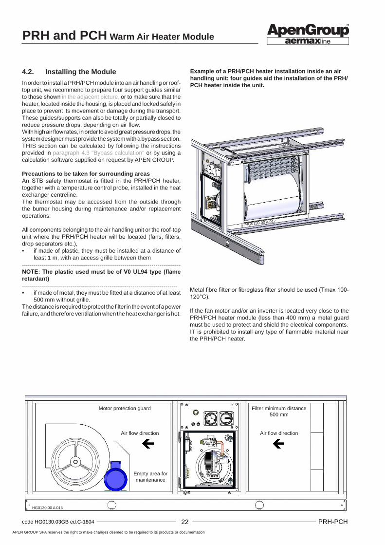
Metal fibre filter or fibreglass filter should be used (Tmax 100-120°C).
If the fan motor and/or an inverter is located very close to the PRH/PCH heater module (less than 400 mm) a metal guard must be used to protect and shield the electrical components.IT is prohibited to install any type of flammable material near the PRH/PCH heater.
Example of a PRH/PCH heater installation inside an air handling unit: four guides aid the installation of the PRH/PCH heater inside the unit.
Filter minimum distance500 mm
Air flow directionAir flow direction
Empty area for maintenance
Motor protection guard

APEN GROUP SPA reserves the right to make changes deemed to be required to its products or documentation
22code HG0130.03GB ed.C-1804 PRH-PCH 23 code HG0130.03GB ed.C-1804PRH-PCH
PRH and PCH Warm Air Heater Module
PCH065PCH020 PCH034 PCH045 PCH080 PCH105
0
1
2
3
4
5
6
7
0 5.000 10.000 15.000 20.000 25.000
Velo
cità
[m/s
]
Portata Aria a 15°C [m3/h]
A -Moduli singoli
VPCH
QPCH
0
20
40
60
80
100
120
140
160
180
1500 3500 5500 7500 9500 11500 13500 15500 17500 19500
∆P [P
a]
Portata Aria a 15°C [m3/h]
A -Moduli singoli
PCH034 PCH045 PCH065PCH020
PCH105
PCH080
QPCH
PPCH
4.3. Bypass Calculation
------------------------------------------------------------------------------------------------------------------------------------------------------------------------IMPORTANT: APEN GROUP can supply on request a programme able to automatically calculate the flow rate and the size of the bypass required for the different types of installation.------------------------------------------------------------------------------------------------------------------------------------------------------------------------
The bypass flow rate calculation can be performed by following the instructions below. As an example, the calculation procedure shown assumes that a PCH heater has been applied. The same procedure can be used for the PRH heater:
A. By using a default pressure drop (for example about 120 Pa) [PPCH] through the PCH section, find out the PCH flow rate [QPCH] going through the PCH by using the AIR FLOW RATES-PRESSURE DROPS diagram;
B. From the FLOW RATE-SPEED diagram, find out, by entering the current flow rate [QPCH], the air flow through the PCH section [VPCH];
C. Calculate the bypass air flow rate [QBYPASS] by subtracting from the air handling or roof-top unit [QTOT] the total air flow rate going through the PCH [QPCH]:
QBYPASS [m3/h] = QTOT - QPCH
D. Calculate the speed of the air going through the bypass section [VBYPASS] using the dynamic pressure formula, considering the air density [ρAIR] as a constant equal to 1.2 kg/m3:
VBYPASS [m/s] = (2*PPCH/ ρARIA)1/2
E. Calculate the bypass section area [ABYPASS] by applying to the bypass section air flow rate the speed of the air going through the bypass [VBYPASS]:
ABYPASS [m2] = QBYPASS [m3/h] / VBYPASS [m/s] /3600 [s/h]

PRH and PCH Warm Air Heater Module
APEN GROUP SPA reserves the right to make changes deemed to be required to its products or documentation
24code HG0130.03GB ed.C-1804 PRH-PCH 25 code HG0130.03GB ed.C-1804PRH-PCH
L
HG0130.00 A 018
H
HG0130.00 A 019
F. After calculating the bypass areas, it is possible to obtain the height required for the bypass if a top bypass is provided or the width of the bypass if it is provided sideways:
TOP BYPASS: x = ABYPASS / L
SIDE BYPASS: y = ABYPASS / H
The bypass area, according to installation requirements, can be provided in the top section and/or in the side section.
-------------------------------------------------------------------------------------------------------------------------------------------------------------------------NOTE: It is advisable to install some manually adjustable shutters or movable grilles where the bypass section is located in order to ensure correct calibration of the equipment during installation.------------------------------------------------------------------------------------------------------------------------------------------------------------------------

APEN GROUP SPA reserves the right to make changes deemed to be required to its products or documentation
24code HG0130.03GB ed.C-1804 PRH-PCH 25 code HG0130.03GB ed.C-1804PRH-PCH
PRH and PCH Warm Air Heater Module
PCHXXX-00V0
HG0130.00 A022
PRHXXXPCHXX0
HG0130.00 A023
HG0130.00 A022
HG0130.00 A020
HG0130.00 A021
4.4. Installing single or multiple modules
MULTIPLE PRH/PCH modules can be assembled in a single Air Handling or Roof-Top unit, in order to achieve greater heat output.The modules can be assembled in parallel; ventilation can be provided on the right or on the left because the PRH/PCH heater uses a single safety device against air overtemperature, which works both for the right and the left air flow. When multiple heaters are installed, safety is always ensured by the thermostat provided on each module.
----------------------------------------------------------------------------------
NOTE: Horizontal or vertical positioning refers to the air flow direction-----------------------------------------------------------------------------------
Fitting a single heater (A System)In standard installations with a single heater, the air flow is horizontal and can have both a right or left direction. The fan can be fitted upstream or downstream of the heat exchanger.
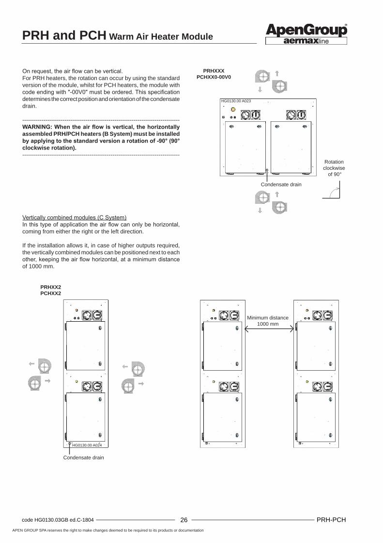
On request, the air flow can be vertical.For PRH heaters, the rotation can occur by using the standard version of the module, whilst for PCH heaters, the module with code ending with "-00V0" must be ordered. This specification determines the correct position and orientation of the condensate drain.----------------------------------------------------------------------------------WARNING: When the air flow is vertical, it can be made horizontal in the PRH/PCH by applying to the standard vertical heat exchanger a rotation of -90° (90° anticlockwise rotation), as shown in the picture; it is not possible to apply a rotation in the opposite direction (90° clockwise rotation).----------------------------------------------------------------------------------
Fitting multiple heaters in parallel (B System and C System)When high heat outputs are generated, a solution with two or more heat exchangers must be used. In this type of installation, it is essential to check that the air flow on the heat exchanger is balanced.
Horizontally combined modules (B System)In the standard configuration, the air flow going through the heat exchanger is horizontal, coming either from the right or from the left.
Condensate drain
PRHXXXPCHXXX
Condensate drain
Rotation anticlockwise
of 90°
Condensate drain
PRH and PCH Warm Air Heater Module
APEN GROUP SPA reserves the right to make changes deemed to be required to its products or documentation
26code HG0130.03GB ed.C-1804 PRH-PCH 27 code HG0130.03GB ed.C-1804PRH-PCH
PRHXXXPCHXX0-00V0
HG0130.00 A023
PRHXX2PCHXX2
HG0130.00 A024
On request, the air flow can be vertical.For PRH heaters, the rotation can occur by using the standard version of the module, whilst for PCH heaters, the module with code ending with "-00V0" must be ordered. This specification determines the correct position and orientation of the condensate drain.
----------------------------------------------------------------------------------WARNING: When the air flow is vertical, the horizontally assembled PRH/PCH heaters (B System) must be installed by applying to the standard version a rotation of -90° (90° clockwise rotation).----------------------------------------------------------------------------------
Vertically combined modules (C System)In this type of application the air flow can only be horizontal, coming from either the right or the left direction.
If the installation allows it, in case of higher outputs required, the vertically combined modules can be positioned next to each other, keeping the air flow horizontal, at a minimum distance of 1000 mm.
Condensate drain
Rotation clockwise
of 90°
Condensate drain
Minimum distance1000 mm
APEN GROUP SPA reserves the right to make changes deemed to be required to its products or documentation
26code HG0130.03GB ed.C-1804 PRH-PCH 27 code HG0130.03GB ed.C-1804PRH-PCH
PRH and PCH Warm Air Heater Module
PRHXXXPCHXX0-00V0
HG0130.00 A 028b
PRHXXXPCHXXX-00V0
HG0130.00 A 026b
PRHXXXPCHXXX
HG0130.00 A 025b
PRHXXXPCHXX0
HG0130.00 A 027b
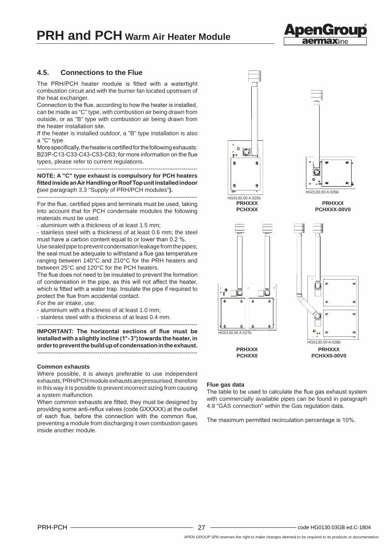
4.5. Connections to the Flue
The PRH/PCH heater module is fitted with a watertight combustion circuit and with the burner fan located upstream of the heat exchanger. Connection to the flue, according to how the heater is installed, can be made as "C" type, with combustion air being drawn from outside, or as "B" type with combustion air being drawn from the heater installation site.If the heater is installed outdoor, a "B" type installation is also a "C" type.More specifically, the heater is certified for the following exhausts: B23P-C13-C33-C43-C53-C63; for more information on the flue types, please refer to current regulations.----------------------------------------------------------------------------------NOTE: A "C" type exhaust is compulsory for PCH heaters fitted inside an Air Handling or Roof Top unit installed indoor (see paragraph 3.3 "Supply of PRH/PCH modules").----------------------------------------------------------------------------------For the flue, certified pipes and terminals must be used, taking into account that for PCH condensate modules the following materials must be used:- aluminium with a thickness of at least 1.5 mm;- stainless steel with a thickness of at least 0.6 mm; the steel must have a carbon content equal to or lower than 0.2 %.Use sealed pipe to prevent condensation leakage from the pipes; the seal must be adequate to withstand a flue gas temperature ranging between 140°C and 210°C for the PRH heaters and between 25°C and 120°C for the PCH heaters.The flue does not need to be insulated to prevent the formation of condensation in the pipe, as this will not affect the heater, which is fitted with a water trap. Insulate the pipe if required to protect the flue from accidental contact. For the air intake, use:- aluminium with a thickness of at least 1.0 mm;- stainless steel with a thickness of at least 0.4 mm.----------------------------------------------------------------------------------IMPORTANT: The horizontal sections of flue must be installed with a slightly incline (1°- 3°) towards the heater, in order to prevent the build up of condensation in the exhaust.----------------------------------------------------------------------------------
Common exhaustsWhere possible, it is always preferable to use independent exhausts; PRH/PCH module exhausts are pressurised, therefore in this way it is possible to prevent incorrect sizing from causing a system malfunction.When common exhausts are fitted, they must be designed by providing some anti-reflux valves (code GXXXXX) at the outlet of each flue, before the connection with the common flue, preventing a module from discharging it own combustion gases inside another module.
Flue gas dataThe table to be used to calculate the flue gas exhaust system with commercially available pipes can be found in paragraph 4.9 "GAS connection" within the Gas regulation data.
The maximum permitted recirculation percentage is 10%.
PRH and PCH Warm Air Heater Module
APEN GROUP SPA reserves the right to make changes deemed to be required to its products or documentation
28code HG0130.03GB ed.C-1804 PRH-PCH 29 code HG0130.03GB ed.C-1804PRH-PCH
PRHXX2PCHXX2
HG0130.00 A 029b
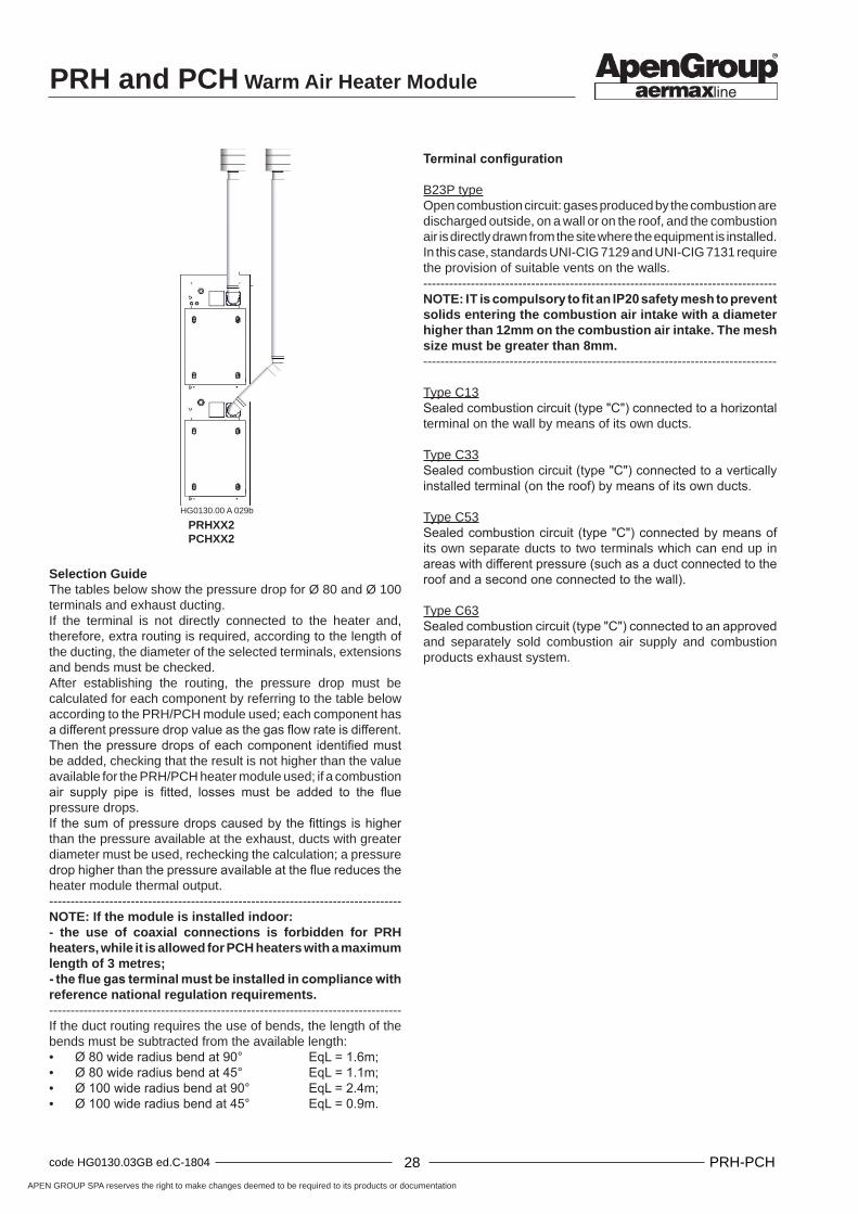
Selection GuideThe tables below show the pressure drop for Ø 80 and Ø 100 terminals and exhaust ducting.If the terminal is not directly connected to the heater and, therefore, extra routing is required, according to the length of the ducting, the diameter of the selected terminals, extensions and bends must be checked.After establishing the routing, the pressure drop must be calculated for each component by referring to the table below according to the PRH/PCH module used; each component has a different pressure drop value as the gas flow rate is different.Then the pressure drops of each component identified must be added, checking that the result is not higher than the value available for the PRH/PCH heater module used; if a combustion air supply pipe is fitted, losses must be added to the flue pressure drops.If the sum of pressure drops caused by the fittings is higher than the pressure available at the exhaust, ducts with greater diameter must be used, rechecking the calculation; a pressure drop higher than the pressure available at the flue reduces the heater module thermal output.----------------------------------------------------------------------------------NOTE: If the module is installed indoor:- the use of coaxial connections is forbidden for PRH heaters, while it is allowed for PCH heaters with a maximum length of 3 metres;- the flue gas terminal must be installed in compliance with reference national regulation requirements.----------------------------------------------------------------------------------If the duct routing requires the use of bends, the length of the bends must be subtracted from the available length:• Ø 80 wide radius bend at 90° EqL = 1.6m;• Ø 80 wide radius bend at 45° EqL = 1.1m;• Ø 100 wide radius bend at 90° EqL = 2.4m;• Ø 100 wide radius bend at 45° EqL = 0.9m.
Terminal configuration
B23P typeOpen combustion circuit: gases produced by the combustion are discharged outside, on a wall or on the roof, and the combustion air is directly drawn from the site where the equipment is installed.In this case, standards UNI-CIG 7129 and UNI-CIG 7131 require the provision of suitable vents on the walls.----------------------------------------------------------------------------------NOTE: IT is compulsory to fit an IP20 safety mesh to prevent solids entering the combustion air intake with a diameter higher than 12mm on the combustion air intake. The mesh size must be greater than 8mm.----------------------------------------------------------------------------------
Type C13Sealed combustion circuit (type "C") connected to a horizontal terminal on the wall by means of its own ducts.
Type C33Sealed combustion circuit (type "C") connected to a vertically installed terminal (on the roof) by means of its own ducts.
Type C53Sealed combustion circuit (type "C") connected by means of its own separate ducts to two terminals which can end up in areas with different pressure (such as a duct connected to the roof and a second one connected to the wall).
Type C63Sealed combustion circuit (type "C") connected to an approved and separately sold combustion air supply and combustion products exhaust system.

APEN GROUP SPA reserves the right to make changes deemed to be required to its products or documentation
28code HG0130.03GB ed.C-1804 PRH-PCH 29 code HG0130.03GB ed.C-1804PRH-PCH
PRH and PCH Warm Air Heater Module
PCH model 020 034 045 065 080 105
Pressure available at the exhaust 80 90 100 120 120 120 [Pa]
Component Pressure drop [Pa] Code
SMOOTH Ø130 PIPE [l=1m] 0.1 0.2 0.3 0.5 0.9 1.3 G15820-13-XXX
Ø130 WALL MOUNTED TERMINAL FROM SEPARATE TO COAX
3.1 4.6 6.3 12.7 20.5 31.1 TC13-13-HC5
Ø130 ROOF MOUNTED TERMINAL FROM SEPARATE TO COAX
1.4 4.4 6.9 14.7 23.0 34.0 TC33-13-VC5K
Ø130 ROOF MOUNTED TERMINAL, WINDPROOF EXHAUST ONLY - 0.3 0.6 2.0 3.7 5.9 TB23-13-VSW
Ø100 SMOOTH PIPE [l=1m] 0.2 0.6 0.9 2.0 3.1 4.7 G15820-10-XXX
BEND Ø100 WIDE RADIUS 90° 0.4 1.3 2.1 4.6 7.4 11.1 G15810-10-90
BEND Ø100 WIDE RADIUS 45° 0.2 0.6 0.9 2.0 3.2 4.8 G15810-10-45
Ø100 WALL MOUNTED TERMINAL FROM SEPARATE TO COAX
4.7 14.1 21.9 46.5 73.1 107.9 TC13-10-HC2
Ø100 ROOF MOUNTED TERMINAL FROM SEPARATE TO COAX
3.8 12.2 19.4 42.5 67.7 101.1 TC33-10-VC2
Ø100 ROOF MOUNTED TERMINAL, WINDPROOF EXHAUST ONLY - 0.3 0.6 2.0 3.7 5.9 TB23-10-VSW
Ø80 SMOOTH PIPE [l=1m] 0.6 2.1 3.3 7.3 11.7 17.5 G15820-08-XXX
BEND Ø80 WIDE RADIUS 90° 1.1 3.4 5.4 11.9 19.0 28.4 G15810-08-90
BEND Ø80 WIDE RADIUS 45° 0.6 1.7 2.7 5.9 9.4 14.1 G15810-08-45
Ø80 WALL MOUNTED TERMINAL FROM SEPARATE TO COAX
9.0 25.4 37.0 70.2 103.4 - TC13-08-HC1
Ø80 ROOF MOUNTED TERMINAL FROM SEPARATE TO COAX
9.2 29.6 45.9 95.9 - - TC33-08-VC1
Ø80 ROOF MOUNTED TERMINAL, WINDPROOF EXHAUST ONLY - 0.1 0.4 1.4 2.7 4.4 TB23-08-VSW
ADAPTOR Ø80/100 0.2 0.7 1.2 2.6 4.1 6.2 G15815-08-10
ADAPTOR Ø100/80 0.2 0.7 1.2 2.6 4.1 6.2 G15815-10-08
ADAPTOR Ø100/130 0.2 0.6 0.9 2.0 3.2 4.8 G15815-10-13
ADAPTOR Ø130/100 0.1 0.4 0.6 1.2 2.0 3.0 G15815-13-10
COMBUSTION AIR UPTAKE ONLY
Ø80 HORIZONTAL AIR UPTAKE ONLY 0.6 2.5 4.1 9.2 14.8 22.2 TB23-08-HS0
Ø100 HORIZONTAL AIR UPTAKE ONLY 0.4 1.3 2.0 4.3 6.8 10.0 TB23-10-HS0
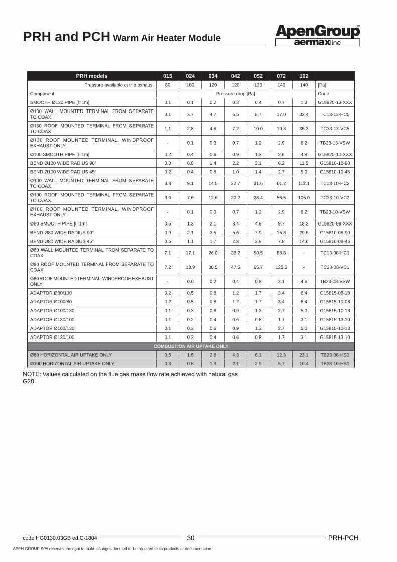
NOTE: Values calculated on the flue gas mass flow rate achieved with natural gas G20.
PRH and PCH Warm Air Heater Module
APEN GROUP SPA reserves the right to make changes deemed to be required to its products or documentation
30code HG0130.03GB ed.C-1804 PRH-PCH 31 code HG0130.03GB ed.C-1804PRH-PCH
PRH models 015 024 034 042 052 072 102
Pressure available at the exhaust 80 100 120 120 130 140 140 [Pa]
Component Pressure drop [Pa] Code
SMOOTH Ø130 PIPE [l=1m] 0.1 0.1 0.2 0.3 0.4 0.7 1.3 G15820-13-XXX
Ø130 WALL MOUNTED TERMINAL FROM SEPARATE TO COAX
3.1 3.7 4.7 6.5 8.7 17.0 32.4 TC13-13-HC5
Ø130 ROOF MOUNTED TERMINAL FROM SEPARATE TO COAX
1.1 2.8 4.6 7.2 10.0 19.3 35.3 TC33-13-VC5
Ø130 ROOF MOUNTED TERMINAL, WINDPROOF EXHAUST ONLY - 0.1 0.3 0.7 1.2 2.9 6.2 TB23-13-VSW
Ø100 SMOOTH PIPE [l=1m] 0.2 0.4 0.6 0.9 1.3 2.6 4.8 G15820-10-XXX
BEND Ø100 WIDE RADIUS 90° 0.3 0.8 1.4 2.2 3.1 6.2 11.5 G15810-10-90
BEND Ø100 WIDE RADIUS 45° 0.2 0.4 0.6 1.0 1.4 2.7 5.0 G15810-10-45
Ø100 WALL MOUNTED TERMINAL FROM SEPARATE TO COAX
3.8 9.1 14.5 22.7 31.6 61.2 112.1 TC13-10-HC2
Ø100 ROOF MOUNTED TERMINAL FROM SEPARATE TO COAX
3.0 7.6 12.6 20.2 28.4 56.5 105.0 TC33-10-VC2
Ø100 ROOF MOUNTED TERMINAL, WINDPROOF EXHAUST ONLY - 0.1 0.3 0.7 1.2 2.9 6.2 TB23-10-VSW
Ø80 SMOOTH PIPE [l=1m] 0.5 1.3 2.1 3.4 4.9 9.7 18.2 G15820-08-XXX
BEND Ø80 WIDE RADIUS 90° 0.9 2.1 3.5 5.6 7.9 15.8 29.5 G15810-08-90
BEND Ø80 WIDE RADIUS 45° 0.5 1.1 1.7 2.8 3.9 7.8 14.6 G15810-08-45
Ø80 WALL MOUNTED TERMINAL FROM SEPARATE TO COAX
7.1 17.1 26.0 38.2 50.5 88.8 - TC13-08-HC1
Ø80 ROOF MOUNTED TERMINAL FROM SEPARATE TO COAX
7.2 18.9 30.5 47.5 65.7 125.5 - TC33-08-VC1
Ø80 ROOF MOUNTED TERMINAL, WINDPROOF EXHAUST ONLY - 0.0 0.2 0.4 0.8 2.1 4.6 TB23-08-VSW
ADAPTOR Ø80/100 0.2 0.5 0.8 1.2 1.7 3.4 6.4 G15815-08-10
ADAPTOR Ø100/80 0.2 0.5 0.8 1.2 1.7 3.4 6.4 G15815-10-08
ADAPTOR Ø100/130 0.1 0.3 0.6 0.9 1.3 2.7 5.0 G15815-10-13
ADAPTOR Ø130/100 0.1 0.2 0.4 0.6 0.8 1.7 3.1 G15815-13-10
ADAPTOR Ø100/130 0.1 0.3 0.6 0.9 1.3 2.7 5.0 G15815-10-13
ADAPTOR Ø130/100 0.1 0.2 0.4 0.6 0.8 1.7 3.1 G15815-13-10
COMBUSTION AIR UPTAKE ONLY
Ø80 HORIZONTAL AIR UPTAKE ONLY 0.5 1.5 2.6 4.3 6.1 12.3 23.1 TB23-08-HS0
Ø100 HORIZONTAL AIR UPTAKE ONLY 0.3 0.8 1.3 2.1 2.9 5.7 10.4 TB23-10-HS0
NOTE: Values calculated on the flue gas mass flow rate achieved with natural gas G20.

APEN GROUP SPA reserves the right to make changes deemed to be required to its products or documentation
30code HG0130.03GB ed.C-1804 PRH-PCH 31 code HG0130.03GB ed.C-1804PRH-PCH
PRH and PCH Warm Air Heater Module
Lmax
HG0130.00 A 058
Vertical B23 terminalOpen combustion circuit, combustion air intake from the room and exhaust to the outdoor.
Lmax of the pipe routing made with the Ø shown, excluding the terminal.The terminal consists of:• Adaptor from PCH or PRH outlet to exhaust Ø (where
necessary);• Wide radius 90° bend;• Roof-mounted terminal, only windproof exhaust.
Ø80 pipes and bends: TB23-08-VSW + G15810-08-90
Mod. PCH
020 034 045 065 080 105
Lmax [m] 30 30 25 14 - -
Mod. PRH
015 024 034 042 052 072 102
Lmax [m] 30 30 30 30 25 10 -
Ø100 pipes and bends: TB23-10-VSW + G15810-10-90 + G15815-08-10
Mod. PCH
020 034 045 065 080 105
Lmax [m] - - - 30 30 20
Mod. PRH
015 024 034 042 052 072 102
Lmax [m] - - - - 30 30 25

PRH and PCH Warm Air Heater Module
APEN GROUP SPA reserves the right to make changes deemed to be required to its products or documentation
32code HG0130.03GB ed.C-1804 PRH-PCH 33 code HG0130.03GB ed.C-1804PRH-PCH
L1maxL2max
HG0130.00 A 059
C33 type coaxial roof-mounted terminalCombustion circuit watertight to the environment. The ducts are connected to the outside with a coaxial terminal.
Lmax of the pipe routing made with the Ø shown, excluding the terminal.The terminal consists of:• Adaptor from PCH or PRH outlet to exhaust Ø (where
necessary);• Adaptor from PCH/PRH outlet to intake Ø (where necessary);• Wide radius 90° bend on the exhaust;• Wide radius 90° bend on the intake;• Roof mounted terminal from separated to coaxial.
----------------------------------------------------------------------------------NOTE: The maximum length available has been split in equal parts between the exhaust (L1max) and the intake (L2max); the lengths between intake and exhaust can also be split differently without exceeding the sum shown.----------------------------------------------------------------------------------
Ø80 pipes and bends: TC33-08-VC1 + 2xG15810-08-90
Mod. PCH
020 034 045 065 080 105
Lmax [m] 30+30 13+13 6+6 - - -
Mod. PRH
015 024 034 042 052 072 102
Lmax [m] 30+30 30+30 20+20 8+8 5+5 - -
Ø100 pipes and bends: TC33-10-VC2 + 2xG15835-08-10 + 2xG15810-10-90
Mod. PCH
020 034 045 065 080 105
Lmax [m] - 30+30 30+30 15+15 5+5 -
Mod. PRH
015 024 034 042 052 072 102
Lmax [m] - - 30+30 30+30 30+30 10+10 -
Ø130 pipes and bends: TC33-13-VC5K + 2xG15815-10-13 + 2xG15810-10-90 + 2xG15810-13-45
Mod. PCH
020 034 045 065 080 105
Lmax [m] - - - - 30+30 20+20
TC33-13-VC5 + 2xG15815-10-13 + 2xG15810-10-90 + 2xG15810-13-45
Mod. PRH
015 024 034 042 052 072 102
Lmax [m] - - - - - - 30+30

APEN GROUP SPA reserves the right to make changes deemed to be required to its products or documentation
32code HG0130.03GB ed.C-1804 PRH-PCH 33 code HG0130.03GB ed.C-1804PRH-PCH
PRH and PCH Warm Air Heater Module
HG0130.00 A 030
HG
0130
_IM
_001
4.6. PCH Condensate Drain
Special attention must be paid to the condensate drain; an incorrectly installed drain, in fact, could jeopardize the correct operation of the equipment.The factors to be taken into account are:• risk of condensation build-up inside the heat exchanger;• risk of condensation water freezing in the pipes;• risk of flue gas discharged from the condensate drain.
Build up of condensation in the heat exchangerDuring normal operation, condensate must not be allowed to accumulate within the heat exchanger.A sensor fitted in the PCH heater internal trap checks and stops the burner operation before the condensate reaches a potentially dangerous level inside the flue gas collection hood. Whilst installing the module inside a unit and, later on, when positioning the unit on the floor, it is essential to make sure that the module, and therefore the heat exchanger, are perfectly level to maintain the typical incline of the tube bundle.
Free drainageIf the unit is installed outdoors, unless the temperatures never drops below freezing, the water could be drained directly outside, without any connections to other pipes. It is essential to check that the condensate flows away from the unit.If the drainage needs to be ducted, it is necessary to install an open type connection (socket pipe), similar to the one in picture below, to prevent ice forming in the pipe from blocking condensate drainage, resulting in water accumulation in the exchanger. If the drain pipe is installed in an outdoor site, it may need to be heated by means of a heating cable.
Connection to the condensate drainThe PCH modules are supplied with a condensate drain on the module outer panel.According to the applications, APEN GROUP can supply a condensate neutraliser kit (code G14303).
According to the type of installation, the module can drain the condensate in the following ways:• free drainage;• drainage to water pipes;• drainage inside the unit (water trap).
Multiple PCH heaters are provided with a single condensate drainage that collects the single internal module exhausts and a lower trap air vent pipe, placed on the front panel near the lower module.
PrecautionsMaterials to be used for the condensation drainage system:• aluminium, stainless steel, silicone or Viton pipe or EPDM
for hot pipes that allow the flue gas to go through;• for cold pipes (water pipes), PVC and any materials suitable
for hot pipes.Do not use copper or galvanised iron pipes.
Drainage into water coursesTaking the condensation drain inside the room to be heated is a good solution in order to avoid the formation of ice; condensation can be drained into water courses or can be collected and treated with alkaline solutions (condensate neutraliser kit, code G14303). The pipe must be routed inside the unit (in warm conditions) up to the point where it enters the site, avoiding external routing.
Drainage inside the unitThis solution is also a good protection against any icing on the water trap; the internal connection between PCH module and water trap can be made using a silicone pipe available at APEN GROUP. For this method of installation it is essential to check that the materials of the water trap of the Air Handling or Roof Top unit where the PCH heater is installed are suitable for the relevant use (e.g.: no galvanised metal sheet).
----------------------------------------------------------------------------------WARNING: Not all countries allow the types of condensation drains described here. Please refer to the requirements specified by local legislation.-------------------------------------------------------------------------------
Condensate drain
Inclined pipe bundle
Socketconnection
Vent pipe

PRH and PCH Warm Air Heater Module
APEN GROUP SPA reserves the right to make changes deemed to be required to its products or documentation
34code HG0130.03GB ed.C-1804 PRH-PCH 35 code HG0130.03GB ed.C-1804PRH-PCH
HG0103_C2 021
HG106_C2 024
4.7. Electrical Connections
Power supplyThe heater must be correctly connected to an effective earthing system, fitted in compliance with current legislation.---------------------------------------------------------------------------------IMPORTANT: Single phase 230 Vac power supply with neutral. Do not mistake the neutral for the live wire.---------------------------------------------------------------------------------For safety reasons, if the live and neutral wires are swapped, the flame control prevents operation by signalling Bloc F10.If power is supplied from a 400V three-phase line, an insulating transformer must be used, connecting a pole to earth and using this pole as neutral. The electrical system and, more specifically, the cable section, must be suitable for the equipment maximum power consumption (see table to the side).Keep power cables away from heat sources.---------------------------------------------------------------------------------NOTE: It is compulsory to fit a multipolar disconnector with suitable electrical protection upstream of the PCH module.------------------------------------------------------------------------------------------------------------------------------------------------------------------IMPORTANT: Powering off the unit before completing the cooling cycle and with machine set to ON is strictly prohibited. Failure to follow these instructions shall invalidate the warranty and cause early deterioration of the heat exchanger.----------------------------------------------------------------------------------
Electrical cable section
Connection must be made using flexible, flame retardant, double-insulated cables. The size of the cable section must be suitable for the equipment power consumption and the distance between the heater and the connection point.
Model
Rat
ed C
ur-
rent
[A]
Inru
sh c
ur-
ren
t Is
/In
[-] Cab
le s
ecti
on
[m
m2 ]
Safe
ty tr
ip [A
]
PRH015 - PRH024PCH020
0.2 2.2 (2+1)x1.5 4
PRH034 - PRH042PCH034
0.3 2.2 (2+1)x1.5 4
PRH052PCH045
0.4 2.2 (2+1)x1.5 4
PRH072PCH065
0.5 2.2 (2+1)x1.5 4
PRH102PCH080
0.6 2.2 (2+1)x1.5 4
PCH105 0.6 2.2 (2+1)x1.5 4
PRH144 - PRH152PCH130 - PCH132
0.9 2.2 (2+1)x1.5 6
PRH204 - PRH202PCH160 - PCH162
1.2 2.2 (2+1)x1.5 6
PCH210 - PCH212 1.2 2.2 (2+1)x1.5 6
PRH310 1.9 2.2 (2+1)x1.5 6
PRH410 2.5 2.2 (2+1)x1.5 6
PCH320 1.9 2.2 (2+1)x1.5 6
PCH420 2.5 2.2 (2+1)x1.5 6
230 V connection 400 V connection with 400/230 V transformer
Remote control connection cable
Power supply cable
Pipe or conduit
High voltage (230 V) and low voltage cables can be housed in the same conduit by using double-insulated cables.
NO! YES

APEN GROUP SPA reserves the right to make changes deemed to be required to its products or documentation
34code HG0130.03GB ed.C-1804 PRH-PCH 35 code HG0130.03GB ed.C-1804PRH-PCH
PRH and PCH Warm Air Heater Module
TITOLO:
DATA:
PROGETTO: FOGLIO
19/07/2014
JG0270.00IT
JG0270.00IT_A
01CLIENTE: APEN
www.apengroup.comDATA FIRMAREV. MODIFICA
DI 01
DIS.: Cduranti
COMMESSA: SCHEMA ELETTRICO PRH015-102
0 1 2 3 4 5 6 7 8 9
A
B
C
D
E
F
G
H
I
J
BW
BL
RD
GY
ACC
IONO
GR
GR
P1
230 VAC
Apparecchiatura controllo fiamma G28800
Ventilatore Bruciatore
BW
BL
PRH015-072
PRH102
BW
BL
BW
BK
BL
RD
GR
OR
BL
RD
GR
BL
BW
BL
WH
BK
YL
RD
Reset e segnalazione allarme remote
TRASFORMATOREACC
24V
230V
VA
G
FN
PEF
PEN
230V
mod. 148
mod. 118-128
54
32
1
24V
HALL
PWM
0V
1 0 2
EVP
EV1
EV2
C1-N
C1-L
C1-PE
N
PE4
F
1314
2324-E/0/I
9 10 11 12 14 15 16 1787
IONO
65
43
21
4241
39 38 37 36 35 34 33 32 31 30 29 28 27 25 2426 23 22 21 20 19 18
-T. W
.1
T.A
ON
/OFF
1314
X1
X2
1314-RS1
X1
X2
-LR1
X1
X2
-LV1
-STB
1
-Y1
PRH Electrical Connections
Single PRH wiring diagram:PRH015 - PRH102code JG0270.00_A
Burner fan
Connections• Line: to terminals L, N, PE.• ON/OFF: to terminals 34-35. Power supply 230V 1~ 50Hz.• High/low flame (Hi-Low): to terminals 16-17. Power supply
24V 1~ 50Hz. (In the absence of Hi/Low, make a jumper between terminals 16 and 17).
• Reset and alarm signalling: to terminals 31-32-33. Power supply 230V 1~ 50Hz, 0.5 A max.
Each PRH module can be set in two ways:• By using only the ON/OFF terminals (34 and 35) and by
making a jumper between Hi-Low terminals (16 and 17).
ON/OFF Hi/Low %modulation
Open Close 0%
Close Close 100%
• By using both the ON/OFF terminals (34 and 35) and the Hi-Low terminals (16 and 17).
ON/OFF Hi/Low %modulation
Open Close 0%
Close Close 100%
Open Open 0%
Close Open 80%
Reset and remote alarm signalling
KEY
P1 connection plug/socketSTB1 safety thermostatEV1 first GAS solenoid valveEV2 main GAS solenoid valveEVP pilot GAS valveIONO flame detection electrodeACC start-up electrodeVAG burner fanTW1 on-off thermostat inside the equipmentRS1 release buttonLR1 lockout indicator lampLV1 power supply indicator lampE/O/I main switch

PRH and PCH Warm Air Heater Module
APEN GROUP SPA reserves the right to make changes deemed to be required to its products or documentation
36code HG0130.03GB ed.C-1804 PRH-PCH 37 code HG0130.03GB ed.C-1804PRH-PCH
PRH Electrical connections of multiple modules
For double PRH modules, the 230Vac connection plug is only one: power supply is connected to the two modules by Apen Group during production.Double PRH modules can be adjusted as described below:• ON-OFF contact: 230Vac terminals 34 and 35 switch each
module on and off; with two clean contacts, the double PRH module operation can be controlled according to a percentage operation of 0%, 50% or 100%.
Module 1 Module 2 Adjustment
ON/OFF Hi/Low ON/OFF Hi/Low %modulation
Close Close Open Close 50%
Close Close Close Close 100%
Open Close Open Close 0%
Open Close Close Close 50%
• ON/OFF contact (terminals 34 at 35 at 230Vac) and high low flame contact (terminals 16 and 17 at 24Vac): with 4 clean contacts, the operation of double PRH modules can be controlled as follows: 0%, 40%, 50%, 80%, 90% or 100%.
Module 1 Module 2 Adjustment
ON/OFF Hi/Low ON/OFF Hi/Low %modulation
Open Open Open Open 0%
Open Open Open Close 0%
Open Open Close Open 40%
Open Open Close Close 50%
Close Close Open Open 50%
Close Close Open Close 50%
Close Close Close Open 90%
Close Close Close Close 100%
Open Close Open Close 0%
Open Close Close Open 40%
Close Open Open Close 40%
Close Open Close Open 80%
Open Close Open Open 0%
Open Close Close Close 50%
Close Open Open Open 40%
Close Open Close Close 90%

APEN GROUP SPA reserves the right to make changes deemed to be required to its products or documentation
36code HG0130.03GB ed.C-1804 PRH-PCH 37 code HG0130.03GB ed.C-1804PRH-PCH
PRH and PCH Warm Air Heater Module
HG0130.00 A 032
HG0130.00 A 033.01
PCH Electrical ConnectionsIf the PCH heater is supplied with a built-in CPU-SMART modulating PCB. The electrical connection to the PCH heater, both single and multiple, is performed via a terminal box located inside the housing. This terminal box contains the connections to the pre-wired module(s) and interfaces with the final user by means of the following connections:
power supply Power to 230 Vac - see table for power absorptions
ON/OFF control Powered at 230 Vac ~ 50Hz - Connect dry contact
common alarm Dry contact - Power to max. 24V (Ac or Dc) 0.5 A
0-10 Vdc modulating signal Dry contact - Power with 0-10 Vdc
ModBus ModBus connection
Interface terminal box
ModBus0/10 Vdc
AlarmON/OFF
230 Vac
1st PCH
2nd PCH
3rd PCH
4th PCH
INLET SIDE
PCH SIDE
Interface terminal box wiring diagram
PCH 4
PCH 1
PCH 2
PCH 3

PRH and PCH Warm Air Heater Module
APEN GROUP SPA reserves the right to make changes deemed to be required to its products or documentation
38code HG0130.03GB ed.C-1804 PRH-PCH 39 code HG0130.03GB ed.C-1804PRH-PCH
H51 = 1
HG0130.00 A 034
PCH ON/OFF ControlThe ON/OFF control (ON/OFF terminals) protects the Air Handling or Roof Top unit operation by stopping the burner(s) when required.The ON/OFF control provides the OK signal applied to ALL PCH heater modules to which it is connected.All the other safety devices must be connected in series to this control (fire dampers, fan control, temperature alarms...) to protect the system operation by stopping the burner. Acting as a monitoring device for the heater, this control must always be closed.---------------------------------------------------------------------------------IMPORTANT: • Do not use jumpers on the terminals to which the ON/
OFF control is connected; connect the safety devices to the ON/OFF terminals;
• The control has priority over the adjustment signals;• The ON/OFF control is 230 V supplied.----------------------------------------------------------------------------------
PCH AdjustmentThe PCH heater allows three power adjustment modes:• 0-10 Vdc;• ModBus;• NTC1 temperature probe.
To correctly set the adjustment parameters, d0 parameter must be programmed, which identifies the type of adjustment associated with the PCH heater.
Function Equipment PCH heater
Flame modulation
d0=2 NTC1
d0=5 0-10Vdc
d0=7 Modbus
PCH 0-10 Vdc modulating signalTHE PCH heater operation can be adjusted with a 0-10 Vdc power modulating signal by connecting to 0Vdc and +10Vdc terminals.The module is preset for 0-10Vdc operation.
This type of adjustment can be carried out directly from the CPU-SMART PCB through the interface panel by setting parameter d0=5 (default value set).
Modulating function and ON/OFFThe default operation type is shown in the diagram below.
The burner linearly modulates the output percentage between VON and 10Vdc, but:• as input voltage decreases: if it is lower than VON the burner
will run at minimum power until its value is higher than VOFF and if it drops below VOFF, the burner will be switched off;
• as the input voltage increases: if it is lower than VON the burner remains off; when it exceeds VON value, it switches on and starts modulating.
Through parameters H52 and H53, VOFF and VON values can be changed.
Modulation operation and ON/OFF

APEN GROUP SPA reserves the right to make changes deemed to be required to its products or documentation
38code HG0130.03GB ed.C-1804 PRH-PCH 39 code HG0130.03GB ed.C-1804PRH-PCH
PRH and PCH Warm Air Heater Module
HG01063 C2 059
H51 = 0
HG0130.00 A 035
Controlling the cascading operation of multiple modulesWhen multiple modules are installed, the signal 0-10 Vdc can be used to switch on and off the single modules in cascade.The 0-10 Vdc signal will be connected in parallel to the modules, whose operation can be cascaded by expanding the PCH module modulation field.The modules are configured according to the following diagram:
Par. Module 1 Module 2 Module 3 Module 4
H52 0.5 1.5 2.5 3.5
H53 0.5 1.0 1.5 1.5
Switches on at
1.0 V 2.5 V 4.0 V 5.0 V
Switches off at 0.5 V 1.5 V 2.5 V 3.5 V
The PCH modules total power consumption must be checked to make sure that it does not exceed the current value available from the regulator output.
The operation type is shown in the diagram below:
EXAMPLE: VOFF = H52 VON = H52 + H53 = VOFF + H53
The default parameters are: H52 = 0.5 V H53 = 0.5 VTherefore VOFF = 0.5 V VON = 1.0 V
This means that the burner will stay on when the input voltage is higher than 1.0 V and will switch off when the input voltage is lower than 0.5 V.
Other two parameters (H54 and H55) determine how long the above described conditions will be kept (the default time set is 10 s.)
Modulation function onlyIT is possible to change modulation behaviour by changing parameter H51:• H51=1 - default value that allows to carry out modulation
and ON/OFF functions;• H51=0 - allows modulation only.
By setting H51=0 the burner linearly modulates the power percentage between VON and 10 Vdc, as shown in the diagram below.
If the input voltage is lower than VON the burner will run at minimum power. To switch the burner off, the ON/OFF contact must be opened.
Modulation only operation
Cascading operation
Heater 1
Heater 2
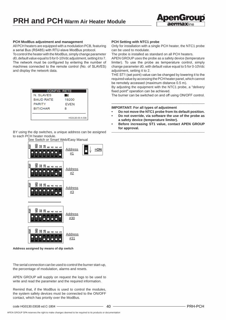
PRH and PCH Warm Air Heater Module
APEN GROUP SPA reserves the right to make changes deemed to be required to its products or documentation
40code HG0130.03GB ed.C-1804 PRH-PCH 41 code HG0130.03GB ed.C-1804PRH-PCH
12481632MD
RS
P
Address #1
12481632MD
RS
P
Address #2
12481632MD
RS
P
Address #3
.............................
12481632MD
RS
P
Address #31
12481632MD
RS
P
Address #30
=ON
EVEN
HG0130.00 A 036
PCH ModBus adjustment and managementAll PCH heaters are equipped with a modulation PCB, featuring a serial Bus (RS485) with RTU-slave ModBus protocol.To control the heater with the ModBus, simply change parameter d0, default value equal to 5 for 0-10Vdc adjustment, setting it to 7.The network must be configured by entering the number of machines connected to the remote control (No. of SLAVES) and display the network data.
BY using the dip switches, a unique address can be assigned to each PCH heater module.
PCH Setting with NTC1 probeOnly for installation with a single PCH heater, the NTC1 probe can be used to modulate.The probe is installed as standard on all PCH heaters. APEN GROUP uses the probe as a safety device (temperature limiter). To use the probe as temperature control, simply change parameter d0, with default value equal to 5 for 0-10Vdc adjustment, setting it to 2.THE ST1 (set point) value can be changed by lowering it to the required value by accessing the PCH heater panel, which cannot be remotely accessed (maximum distance 0.5 m).By adjusting the equipment with the NTC1 probe, a "delivery fixed point" operation can be achieved.The burner can be switched on and off using ON/OFF control.
-----------------------------------------------------------------------------------IMPORTANT: For all types of adjustment• Do not move the NTC1 probe from its default position.• Do not override, via software the use of the probe as
a safety device (temperature limiter).• Before increasing ST1 value, contact APEN GROUP
for approval.----------------------------------------------------------------------------------
The serial connection can be used to control the burner start-up, the percentage of modulation, alarms and resets.
APEN GROUP will supply on request the logs to be used to write and read the parameter and the required information.
Remind that, if the ModBus is used to control the modules, the system safety devices must be connected to the ON/OFF contact, which has priority over the ModBus.
See Switch or Smart Web/Easy Manual
Address assigned by means of dip switch

APEN GROUP SPA reserves the right to make changes deemed to be required to its products or documentation
40code HG0130.03GB ed.C-1804 PRH-PCH 41 code HG0130.03GB ed.C-1804PRH-PCH
PRH and PCH Warm Air Heater Module
M1
M2
4321
+VIN GND A+ B-
M1
CPU-SMART # 1
CPU-SMART # 2
CPU-SMART # n
D-D+GND+12VD-D+GND+12V D-D+GND+12V
109
87
65
43
21ID1
GN
DID
2G
ND
NT
C1
AG
ND
NT
C2
AG
ND
AN
3/N
TC
3A
GN
D
M2
PCH Switching the Controls to remote mode (Smart Web/Easy)The PCH heater controls can be operated remotely with the Smart Web or Easy chronothermostat (OPTIONAL code G23700 - Web, G23500 - Easy), that uses the ModBus protocol and can
When the Smart Web/Easy panel is used as a supervisor/display, an electrical resistance must be connected instead of the ambient probe to leave the Smart Control always demanding heating and address the modules.
When the Smart Web/Easy panel is used to control the setting, you must:• index the PCH heater modules from 1 to 4 by entering the
address of each module through the dip switch;• connect one to three NTC probes to the Smart Web/Easy;• set the adjustment parameters both on the PCB and the
Smart Web/Easy.The NTC probe which can be connected must be of 10 KΩ, β 3435 type.The probe must be connected to the terminals 5/6, 7/8 or 9/10 and can be placed locally or elsewhere, according to the settings required.----------------------------------------------------------------------------------NOTE: This probe is not the NTC1 probe, but an optional external probe (code G07202).---------------------------------------------------------------------------------.The Smart Web/Easy is powered through 24 Vdc voltage.To enable the demand for heat, close the Smart Web/Easy ID1 input.
control up to 32 heaters.To use the Smart Web/Easy as a temperature control, simply change the d0 parameter on each PCH heater with a default value of 5 set for 0-10Vdc range, setting it to 7 (ModBus control).The Smart Web/Easy can be used:• as a supervisor/display;• as a supervisor/display and controller (active adjustment
part).
See Manual or Smart Web/Easy Diagram
Smart Web/Easy electric connections
ID2 digital input(NOT implemented)
Remote ON/OFF contact
NTC1 external probe - optional (code G07202)
NTC2 external probe - optional (code G07202)
NTC3 external probe - optional (code G07202)
Contacts jumperID2-IDC2
Setting switchHeater address
MOD-BUS connection
Power supply connection
PRH and PCH Warm Air Heater Module
APEN GROUP SPA reserves the right to make changes deemed to be required to its products or documentation
42code HG0130.03GB ed.C-1804 PRH-PCH 43 code HG0130.03GB ed.C-1804PRH-PCH
The Smart Web/Easy displays the following information: burner on/off, percentage of modulation, alarms and resets.
The Smart Web or Easy requires you to:• specify that the probe is external (remote);• change the number of slaves according to requirements;• set cascaded adjustment (setting: "cascade") and the
relevant PID values. • set the heating mode (operation: "heating") and the desired
set point value, locally or remotely.• set the xd cascade differential value.
For more information on how to remotely operate the controls with the Smart Web/Easy, please refer to the manual HG0060.00W "Use, installation and programming Manual of theCHRONOTHERMOSTAT of the SMART WEB / SMART EASY series".
Cascading operationThe Smart Web/Easy, through its PID setting, calculates the modulation percentage and compares the calculated value with the operation percentage of each module:
PCH on % = 100% / no. of modulesand switches on the required modules accordingly.The xd cascading differential is applied when the module is switched on and off to avoid continuous module activations and deactivations.The modulation percentage sent to the modules is always the same.
EXAMPLE:With two modules:
PCH on % = 100% / 2 = 50%If xd = 10% the second module is switched on at 60% and off at 40%.

APEN GROUP SPA reserves the right to make changes deemed to be required to its products or documentation
42code HG0130.03GB ed.C-1804 PRH-PCH 43 code HG0130.03GB ed.C-1804PRH-PCH
PRH and PCH Warm Air Heater Module
TIT
OLO
:
DA
TA
:
PR
OG
ET
TO
:F
OG
LIO
09
/07/2
015
JG
038
5.0
1IT
00
CLI
EN
TE
:A
PE
N
ww
w.a
pengro
up.c
om
DA
TA
FIR
MA
RE
V.
MO
DIF
ICA
DI
01
DIS
.:C
dura
nti
CO
MM
ES
SA
:S
CH
EM
A E
LET
TR
ICO
PC
H0
15-1
02
01
23
45
67
89
ABCDEFGHIJ
BW
OR
BL
BK
BW
BL
RE
D
GY
AC
C
ION
O
GR
GR
230VAC
ACF-G10900
PCBOARD-G16800.XX
BURNERFAN
PCH0
20-0
65
PCH0
80-1
05B
W
BL
YG
YG
BL
BW
BW
BK
BL
BL
BW
GR
YL
RD
WT
GY
PK
D+
D-
0V
10V
ALA
RM
ALA
RM
ON
/OF
F
ON
/OF
F
BL
YG
BW
NTC1
N PE L1
KO
ND
GY
321678 5 4 3 2 1
SONDANTC
24V
230V
54321
24V
HALL
PW
M
0V
VAG
FNPEFPEN230V
mod
. 148
mod
. 118
-128
1
R 20
F9
R 56
C2
6
Q1
R 8
CN15R104
R2
2
R 87
C 49
F5
D6
C50
C3
2
R39
U15
C41
Q2
CN11
R 48
U1
CN12
C2
8
R 61
R2
4
U8
C 21
F3
R 3
R5
0
R2
7
F4
U2
R 16
R1
U4
R2
9
CN
04
C42
R 44
R 66
F6
R 52
TP1
R8
3
R4
R 73
R101
C54
C55
C18
R 17
U9
R 65
R2
R9
1
C3
5
R 97
C 6 OP1
L1
DZ1
C 1
T2
D11 D1
6
C1
2
R9
0
C3
4
R103
F1
D7
R 37
R 7
R 18
R 74
CN
13
D1
7
R5
C3
7
R9
9
C3
1
C 2
SW
1
R9
4
C52
R3
4
U3
F8
C56
R8
9
C 14
R 25
F2
R106
R7
7
R4
3
C 27
R4
9
R 10
R 58
C4
0
C 20
C 8
Q5
R 45
R 62
RL2
C 22
R 64
D3
C 23
CN
01
LC1
R32
RL1
C51
U11
LC6
C1
1
R7
0
R4
1
R40
D9 D
1
R3
5
R110
R 42
R31
R5
9
R9
6
TS1
R3
8
D5
D20
Q3
R23
D2
R 55
R 26
CN
02
D1
0
C2
9
R100
C1
5
C3
3
D13
R 19
R7
8R
108
R1
02
R7
6
R7
9
D8
C 43
TS2
C 5
C 10
R 9
U14
LC5LC2
C3
8
C 17
Q6
VR1
CN08
C 3
R 71
R9
5
R 72
R 12
T1
C3
6
C53
R107
U5
D4
R8
2
XT
1
C 48
F7
R 88
C3
0
R 28
R 14
C3
9
R6
3
R5
4
R 11
U13
R 53
C4
6
RR
1
C1
6
C45
R109
R 13
C 44
CN
06
LC3
J1
U10
R3
0
R 57
R 15
R21
R3
6
CN14
R 98
R8
6
R 60C 9
D14
D19
D12
R 69
CN
07
R8
4
C 7
D1
5
D21
R9
3
RD
1
C47
R105
R 81
LC4
R 47
R 67
R9
2
R5
1
R 68
Q4
R8
5
R7
5
CN05
C 25
U12
CN
03
C 13
R6
R 80
R3
3
C 4
D18
RE
SB
EVP
EV2
EV1
-JP
1
RE
SE
T - O
PZ
13 14
N
L1
LFN
N
N
NC
IDC1
ID1
LBW
GND
B1
GND
+5V
B3
GND
B2
+5V
NTC
3
NTC
3
NTC
2
NTC
2
NTC
1
NTC
1
D-
D+
GN
D
+12V
+28V
HALL
GND
PWM
ID2
IDC2
ID3
IDC4
ID4
IDC5
ID5
IDC6
ID6
N.O.
N.C.
COM
Q2
GND
Y1
Y2
+28VN
24V
dc L
GN
D
7Vdc
24V
ac
CLK
DA
T
ION
O
AC
C
PE
NL
GN
D
7Vdc
CLK
24V
ac
DA
T
24V
dc
STB
STB VG
1
VG
P
VG
P
VG
2
VG
2
VG
1
-TS
-Y1
M1
M2
PCH Wiring diagramsSingle PCH wiring diagram: PCH020 - PCH105(code JG0385.01_A)
Connection details are described in paragraph 4.7 "Electrical connections".
Con
nect
ions
Line
: te
rmin
als
L1, N
, PE
Pow
er to
230
Vac
- s
ee ta
ble
for
pow
er a
bsor
ptio
ns
On/
Off:
te
rmin
als
7-8
Pow
ered
at 2
30 V
ac ~
50H
z -
Con
nect
dry
con
tact
Ala
rm:
term
inal
s 5-
6 D
ry c
onta
ct -
Pow
er to
max
. 24
V (A
C o
r DC
) 0.5
A
0-10
V:
term
inal
s 3-
4 D
ry c
onta
ct -
Pow
er w
ith 0
-10
Vdc
Mod
Bus
: te
rmin
als
1-2
KE
Y
TS
sa
fety
ther
mos
tat
EV1
first
GAS
sol
enoi
d va
lve
EV
2 m
ain
GA
S s
olen
oid
valv
eE
VP
pi
lot G
AS
val
veK
ON
D
cond
ensa
tion
dete
ctio
n el
ectr
ode
ION
O
flam
e de
tect
ion
elec
trode
AC
C
star
t-up
ele
ctro
deAC
F fla
me
mon
itorin
g eq
uipm
ent
VA
G
burn
er fa
nN
TC
1 te
mpe
ratu
re p
robe
CAB
LE C
OLO
UR
KEY
WT
w
hite
OR
or
ange
RD
re
dP
K
pink
BL
blue
GR
gr
een
YG
ye
llow
-gre
enB
W
brow
nG
Y
grey
BK
bl
ack
YL
yello
w

PRH and PCH Warm Air Heater Module
APEN GROUP SPA reserves the right to make changes deemed to be required to its products or documentation
44code HG0130.03GB ed.C-1804 PRH-PCH 45 code HG0130.03GB ed.C-1804PRH-PCH
HG0130.00 A 057
4.8. Interface panel
PRHThe heater housing features an interface panel consisting of two buttons provided to reset the equipment block and for summer/winter switching and by two lamps provided for block signalling and voltage presence check.In the event of a block, the PRH heater can be manually unblocked directly from the machine by pressing the proper button for more than 1 second. Make sure to leave the switch on winter side, otherwise the heater appears to be switched off.
PCHThe PCH heater is fitted as standard with a multifunction LCD panel located inside the burner housing, and is used to control, configure and diagnose all operating parameters of the equipment.The instrument panel is fitted with a red 3-digit LCD display and with four function keys: ↑ , ↓ , ESC and ENTER; the display allows the user to display the heater operating mode and its Faults.It also allows the service centre to change the main operating parameters.Changing parameters requires a password.
The machine status is shown on the display by the following
wordings:rdy the machine is on without burner flame, it is waiting for the ON control and/or the heat demand from the thermostat
On the machine is on with burner flame on;OFF the machine has been switched off through the LCD control; any heat demands will be ignored. To switch the PCH heater on, the LCD display must show "operation ON";Fxx Fault detected.During normal operation, the display will show the wording On if the burner is on; rdy when the boiler is being switched off or the room temperature has been reached.If the address is different from 0, the writing Axx will appear, alternated with On and rdy.
In the event of communication problems between CPU-SMART PCB and LCD panel, the word CPU will flash on the display if the problem is caused by the CPU; three flashing dots will be displayed if the problem is caused by the display PCB. If needs be, check that the display and the PCB are correctly connected and that the small cable RJ11 is securely held in the connector.
Parameters and faults are described in the manuals:• HG0131.00IT "PCH condensing warm air heater module
maintenance and service manual".• HG0161.00IT "PRH warm air heater module maintenance
and service manual".
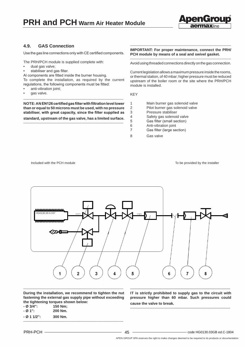
APEN GROUP SPA reserves the right to make changes deemed to be required to its products or documentation
44code HG0130.03GB ed.C-1804 PRH-PCH 45 code HG0130.03GB ed.C-1804PRH-PCH
PRH and PCH Warm Air Heater Module
HG0130.00 A 037
4.9. GAS Connection
Use the gas line connections only with CE certified components.
The PRH/PCH module is supplied complete with:• dual gas valve;• stabiliser and gas filter.Al components are fitted inside the burner housing.To complete the installation, as required by the current regulations, the following components must be fitted:• anti-vibration joint;• gas valve.
---------------------------------------------------------------------------------NOTE: AN EN126 certified gas filter with filtration level lower than or equal to 50 microns must be used, with no pressure stabiliser, with great capacity, since the filter supplied as standard, upstream of the gas valve, has a limited surface.---------------------------------------------------------------------------------
----------------------------------------------------------------------------------IMPORTANT: For proper maintenance, connect the PRH/PCH module by means of a seal and swivel gasket.----------------------------------------------------------------------------------Avoid using threaded connections directly on the gas connection.
Current legislation allows a maximum pressure inside the rooms, or thermal station, of 40 mbar; higher pressure must be reduced upstream of the boiler room or the site where the PRH/PCH module is installed.
KEY
1 Main burner gas solenoid valve2 Pilot burner gas solenoid valve3 Pressure stabiliser4 Safety gas solenoid valve5 Gas filter (small section)6 Anti-vibration joint7 Gas filter (large section)8 Gas valve
To be provided by the installerIncluded with the PCH module
---------------------------------------------------------------------------------IT is strictly prohibited to supply gas to the circuit with pressure higher than 60 mbar. Such pressures could
cause the valve to break.---------------------------------------------------------------------------------
---------------------------------------------------------------------------------During the installation, we recommend to tighten the nut fastening the external gas supply pipe without exceeding the tightening torques shown below:- Ø 3/4'': 150 Nm;- Ø 1'': 200 Nm.
- Ø 1 1/2'': 300 Nm.---------------------------------------------------------------------------------

PRH and PCH Warm Air Heater Module
APEN GROUP SPA reserves the right to make changes deemed to be required to its products or documentation
46code HG0130.03GB ed.C-1804 PRH-PCH 47 code HG0130.03GB ed.C-1804PRH-PCH
HG0130.00 A 039HG0130.00 A 038
10mHG0130.00 A 040
Gas pipe installationSpecial attention must be paid when fitting the gas supply pipes to allow the burner housing door to open, as shown in the figures below.
---------------------------------------------------------------------------------If pressure is higher than 60mbar, a pressure reducer must be installed at a distance of at least 10m and no pressure stabiliser must be fitted between the pressure reducer and the heater, but leaving the gas filter.---------------------------------------------------------------------------------
NO YES
Pressure reducer↑ Max 60 mbar

APEN GROUP SPA reserves the right to make changes deemed to be required to its products or documentation
46code HG0130.03GB ed.C-1804 PRH-PCH 47 code HG0130.03GB ed.C-1804PRH-PCH
PRH and PCH Warm Air Heater Module
Country Table - Gas Category
Country Category Gas Pressure Gas Pressure
AT, CH II2H3B/P G20 20 mbar G30/G31 50 mbarBE <70kW I2E(S)B, I3P G20/G25 20/25 mbar G31 37 mbarBE >70kW I2E(R)B, I3P G20/G25 20/25 mbar G31 37 mbarDE II2ELL3B/P G20/G25 20 mbar G30/G31 50 mbarDK, FI, GR, SE, NO, IT, CZ, EE, LT, SI, AL, MK, BG, RO, HR, TR
II2H3B/P G20 20 mbar G30/G31 30 mbar
ES, GB, IE, PT, SK II2H3P G20 20 mbar G31 37 mbarFR II2Esi3P G20/G25 20/25 mbar G31 37 mbarLU II2E3P G20/G25 20 mbar G31 37/50 mbarNL (up to 31/12/2017) II2L3B/P G25 25 mbar G30/G31 50 mbarNL (from 01/01/2018) II2EK3B/P G20/G25.3 20/25 mbar G30/G31 30 mbarHU II2HS3B/P G20/G25.1 25 mbar G30/G31 30 mbarCY, MT I3B/P G30/G31 30 mbarLV I2H G20 20 mbarIS I3P G31 37 mbar
PL II2ELwLs-3B/P
G20/G27/G2.350 20/13 mbar G30/G31 37 mbar
RU II2H3B/P G20 20 mbar G30/G31 30 mbar
The following information is clearly printed on the equipment packaging: country of destination, gas category and equipment code.The code allows finding out the factory settings.
NOTE: In compliance with standards EN1020, EN 437 and ISO3166, GB refers to the United Kingdom.
Codes with no extension:• PCH020IT if there is no extension, it means that the equipment has been tested and set to run with natural gas
[G20]
Codes with extension:The fourth letter indicates the type of gas the equipment has been set up for:• PCH020FR-xxx0 0 indicates that the equipment has been tested and set up for natural gas [G20];• PCH020MT-xxx1 1 indicates that the equipment has been tested and set up for LPG [G31];• PCH020NL-xxx2 2 indicates that the equipment has been tested and set up for 'L' natural gas [G25], or ‘K’ [G25.3];• PCH020HU-xxx3 3 indicates that the equipment has been tested and set up for natural gas [G25.1];• PCH020PL-xxx4 4 indicates that the equipment has been tested and set up for gas [G2.350].
Another adhesive label, located near the fuel connection of the equipment, specifically indicates the type of gas and the supply pressure for which the equipment has been set up and tested.
Suitable for the G+ Gas [Only for Holland]“The appliance was configured for the appliance category K (I2K) and is suitable for the use of G and G+ distribution gases according to the specifications as included in the NTA 8837:2012 Annex D with a Wobbe index of 43.46 – 45.3 MJ/m3 (dry, 0 °C, upper value) or 41.23 – 42.98 (dry, 15 °C, lower value).This appliance can moreover be converted and/or be calibrated for the appliance category E (I2E). This therefore implies that the appliance “is suitable for G+ gas and H gas or is demonstrably suitable for G+ gas and can demonstrably be made suitable for H gas” within the meaning of the “Dutch Decree of 10 May 2016 regarding amendment of the Dutch Gas Appliances Decree and the Dutch Commodities (Administrative Fines) Act in connection with the changing composition of gas in the Netherlands as well as technical amendment of some other decrees”.

PRH and PCH Warm Air Heater Module
APEN GROUP SPA reserves the right to make changes deemed to be required to its products or documentation
48code HG0130.03GB ed.C-1804 PRH-PCH 49 code HG0130.03GB ed.C-1804PRH-PCH
PRH Gas Settings Table
TYPE OF GAS G20 - Cat. E-HTYPE OF MACHINE PRH015 PRH024 PRH034 PRH042 PRH052 PRH072 PRH102
min max min max min max min max min max min max min maxCATEGORY according to the country of destination - see reference tableSUPPLY PRESSURE [mbar] 20 [min 15-max 25] *PILOT NOZZLE Ø [mm] 0.7GAS CONSUMPTION (15°C-1013mbar) [m3/h] 1.38 1.75 2.31 2.86 2.91 3.68 3.76 4.66 4.49 5.52 6.35 7.78 8.66 10.58
CARBON DIOXIDE -CO2 CONTENT
[%] 8.7 8.8 8.7 8.8 8.7 8.8 8.7 8.8 8.7 8.8 8.7 8.8 8.7 8.8
FLUE GAS TEMPERATURE [°C] 155 204 145 191 143 182 155 194 152 187 146 184 142 188FLUE GAS MASS FLOW RATE (MAX.) [kg/h] 27.7 45.3 58.4 73.9 87.7 123.4 168.0
GAS ORIFICE PLATE [mm] 3.9 5.7 6.4 7.7 9.4 9.6 11.2
AIR ORIFICE PLATE [mm] 15.5 Not required
Not required
Not required
Not required
Not required
Not required
* For Hungary, supply pressure is 25 mbar
TYPE OF GAS G25 - Cat. L-LLTYPE OF MACHINE PRH015 PRH024 PRH034 PRH042 PRH052 PRH072 PRH102
min max min max min max min max min max min max min maxCATEGORY according to the country of destination - see reference tableSUPPLY PRESSURE [mbar] 25 [min 18-max 30] *PILOT NOZZLE Ø [mm] 0.7GAS CONSUMPTION (15°C-1013mbar) [m3/h] 1.60 2.03 2.68 3.32 3.38 4.28 4.37 5.41 5.22 6.42 7.38 9.04 10.06 12.30
CARBON DIOXIDE -CO2 CONTENT
[%] 8.6 8.7 8.8 8.9 8.8 8.9 8.9 9.0 8.7 8.8 8.7 8.8 8.7 8.8
FLUE GAS TEMPERATURE [°C] 155 204 145 191 143 182 155 194 152 187 146 184 142 188
GAS ORIFICE PLATE [mm] 4.7 6.8 7.7 9.0 8,3 Not required
Not required
AIR ORIFICE PLATE [mm] 15.5 Not required
Not required
Not required
Not required
Not required
Not required
* For Germany, supply pressure is 20 mbar
TYPE OF GAS G25.3 - Cat. K (Only Netherlands - from 01/01/2018)TYPE OF MACHINE PRH015 PRH024 PRH034 PRH042 PRH052 PRH072 PRH102
min max min max min max min max min max min max min maxCATEGORY according to the country of destination - see reference tableSUPPLY PRESSURE [mbar] 25 [min 20-max 30] *PILOT NOZZLE Ø [mm] 0.7GAS CONSUMPTION (15°C-1013mbar) [m3/h] 1,56 1,99 2,62 3,25 3,31 4,19 4,27 5,29 5,10 6,28 7,22 8,84 9,84 12,03
CARBON DIOXIDE -CO2 CONTENT
[%] 8,7 8,9 8,7 8,9 8,8 8,9 8,8 8,9 8,8 8,9 8,8 8,9 8,7 9
FLUE GAS TEMPERATURE [°C] 155 204 145 191 140 170 155 194 158 165 146 184 142 188
GAS ORIFICE PLATE [mm] 4.7 6.8 7.7 9.0 8,3 Not required
Not required
AIR ORIFICE PLATE [mm] 15.5 Not required
Not required
Not required
Not required
Not required
Not required
* For Germany, supply pressure is 20 mbar

APEN GROUP SPA reserves the right to make changes deemed to be required to its products or documentation
48code HG0130.03GB ed.C-1804 PRH-PCH 49 code HG0130.03GB ed.C-1804PRH-PCH
PRH and PCH Warm Air Heater Module
TYPE OF GAS G2.350 - Cat. Ls (Only for PL-Poland)TYPE OF MACHINE PRH015 PRH024 PRH034 PRH042 PRH052 PRH072*
min max min max min max min max min max min maxCATEGORY according to the country of destination - see reference tableSUPPLY PRESSURE [mbar] 13 [min 10-max 16] PILOT NOZZLE Ø [mm] 0.75GAS CONSUMPTION (15°C-1013mbar) [m3/h] 1.93 2.44 3.23 4.00 4.07 5.16 5.26 6.52 6.28 7.73 8.89 10.89
CARBON DIOXIDE -CO2 CONTENT
[%] 8.5 8.8 8.7 8.8 8.8 8.9 8.7 8.8 8.7 8.8 8.6 8.7
FLUE GAS TEMPERATURE [°C] 155 204 145 191 143 182 155 194 152 187 120 152
GAS ORIFICE PLATE [mm] 5.8 11.0 Not required
Not required
Not required
Not required
AIR ORIFICE PLATE [mm] 15.5 Not required
Not required
Not required
Not required 29
* Maximum nominal power output 63.0 kW / minimum 51.0 kW
TYPE OF GAS G25.1 - Cat. S (Only for HU-Hungary)TYPE OF MACHINE PRH015 PRH024 PRH034 PRH042* PRH052 PRH072
min max min max min max min max min max min maxCATEGORY according to the country of destination - see reference tableSUPPLY PRESSURE [mbar] 25 [min 20-max 33]PILOT NOZZLE Ø [mm] 0.70GAS CONSUMPTION (15°C-1013mbar) [m3/h] 1.60 2.03 2.68 3.32 3.38 4.28 4.36 5.41 5.21 6.41 7.37 9.03
CARBON DIOXIDE -CO2 CONTENT
[%] 8.9 9.0 9.1 9.2 8.8 8.9 8.9 9.5 9.5 9.6 9.5 9.6
FLUE GAS TEMPERATURE [°C] 155 204 145 191 143 182 146 194 152 187 146 184
GAS ORIFICE PLATE [mm] 4.7 6.8 7.7 9.0 Not required
Not required
AIR ORIFICE PLATE [mm] 15.5 Not required
Not required
Not required
Not required
Not required
* Maximum nominal heat output 42.0 kW
TYPE OF GAS G27 - Cat. Lw [former GZ41.5] (Only for PL-Poland)TYPE OF MACHINE PRH015 PRH024 PRH034 PRH042 PRH052 PRH072
min max min max min max min max min max min maxCATEGORY according to the country of destination - see reference tableSUPPLY PRESSURE [mbar] 20 [min 16-max 23]PILOT NOZZLE Ø [mm] 0.70GAS CONSUMPTION (15°C-1013mbar) [m3/h] 1.55 1.96 2.60 3.21 3.27 4.14 4.23 5.24 5.05 6.21 7.14 8.75
CARBON DIOXIDE -CO2 CONTENT
[%] 8.9 9 8.8 8.9 8.8 8.9 8.8 8.9 8.8 8.9 8.7 8.8
FLUE GAS TEMPERATURE [°C] 155 204 145 191 143 182 146 194 152 187 146 184
GAS ORIFICE PLATE [mm] 4.9 7.2 8.5 9.8 Not required
Not required
AIR ORIFICE PLATE [mm] 15.5 Not required
Not required
Not required
Not required
Not required

PRH and PCH Warm Air Heater Module
APEN GROUP SPA reserves the right to make changes deemed to be required to its products or documentation
50code HG0130.03GB ed.C-1804 PRH-PCH 51 code HG0130.03GB ed.C-1804PRH-PCH
TYPE OF GAS G30 - Cat. 3B-PTYPE OF MACHINE PRH015 PRH024 PRH034 PRH042 PRH052 PRH072 PRH102
min max min max min max min max min max min max min* max**CATEGORY according to the country of destination - see reference tableSUPPLY PRESSURE [mbar] 30 [min 25-max 35] - 50 [min 42.5-max 57.5] PILOT NOZZLE Ø [mm] 0.51GAS CONSUMPTION (15°C-1013mbar) [kg/h] 1.08 1.37 1.81 2.24 2.28 2.89 2.76 3.65 3.30 4.33 4.98 6.10 6.97 8.63
CARBON DIOXIDE -CO2 CONTENT
[%] 9.9 10.0 9.9 10.0 9.9 10.0 9.7 9.8 9.7 9.9 10.2 10.3 10.3 10.4
FLUE GAS TEMPERATURE [°C] 155 204 145 191 143 182 155 194 152 187 146 184 142 188GAS ORIFICE PLATE [mm] 2.8 4.0 4.5 5.6 6.1 6.9 7.8
AIR ORIFICE PLATE [mm] 15.5 Not required
Not required
Not required
Not required
Not required
Not required
* Minimum rated heat output 84.0 kW * Maximum rated heat output 104.0 kW
TYPE OF GAS G31 - Cat. 3PTYPE OF MACHINE PRH015 PRH024 PRH034 PRH042 PRH052 PRH072 PRH102
min max min max min max min max min max min max min maxCATEGORY according to the country of destination - see reference tableSUPPLY PRESSURE [mbar] 30 [min 25-max 35] - 37 [min 25-max 45] - 50 [min 42.5-max 57.5] PILOT NOZZLE Ø [mm] 0.51GAS CONSUMPTION (15°C-1013mbar) [kg/h] 1.06 1.35 1.78 2.21 2.25 2.85 2.90 3.60 3.47 4.27 4.91 6.01 6.69 8.18
CARBON DIOXIDE -CO2 CONTENT
[%] 9.7 9.8 9.7 9.8 9.6 9.7 9.6 9.7 9.7 9.8 9.7 9.8 9.7 9.8
FLUE GAS TEMPERATURE [°C] 154 206 150 195 145 185 155 194 149 187 145 186 150 188FLUE GAS MASS FLOW RATE (MAX.) [kg/h] 21.2 34.7 45.0 56.9 67.1 94.4 128.5
GAS ORIFICE PLATE [mm] 2.8 4.0 4.5 5.6 6.1 6.9 7.8
AIR ORIFICE PLATE [mm] 15.5 Not required
Not required
Not required
Not required
Not required
Not required
NOTE: For PRH144 and PRH152 gas consumption and mass flow rate values are twice the PRH072 values.For PRH202 and PRH204 gas consumption and mass flow rate values are twice the PRH102 values.For PRH310 gas consumption and mass flow rates are three times higher than the PRH102.For PRH410 gas consumption and mass flow rates are four times higher than the PRH102.

APEN GROUP SPA reserves the right to make changes deemed to be required to its products or documentation
50code HG0130.03GB ed.C-1804 PRH-PCH 51 code HG0130.03GB ed.C-1804PRH-PCH
PRH and PCH Warm Air Heater Module
PCH Gas settings table
TYPE OF GAS G20 - Cat. E-HTYPE OF MACHINE PCH020 PCH034 PCH045 PCH065 PCH080 PCH105Output min max min max min max min max min max min maxCATEGORY according to the country of destination - see reference tableSUPPLY PRESSURE [mbar] 20 [min 17-max 25] *PILOT NOZZLE Ø [mm] 0.7GAS CONSUMPTION (15°C-1013mbar) [m3/h] 0.51 2.01 0.80 3.69 0.90 4.44 1.31 6.88 1.74 8.68 2.22 10.58
CARBON DIOXIDE -CO2 CONTENT
[%] 8.8 9.1 8.7 9.1 8.7 9.1 8.7 9.1 8.7 9.1 8.5 9.1
FLUE GAS TEMPERATURE [°C] 39 113 31 94 30 94 31 86 26 70 28 80FLUE GAS MASS FLOW RATE (MAX.) [kg/h] 31 57 72 107 135 165
GAS ORIFICE PLATE [mm] 5.8 7.4 7.5 11 12.2 15.8
AIR ORIFICE PLATE [mm] Not required
Not required
Not required
Not required
Not required
Not required
* For Hungary, supply pressure is 25 mbar
TYPE OF GAS G25 - Cat. L-LLTYPE OF MACHINE PCH020 PCH034 PCH045 PCH065 PCH080 PCH105Output min max min max min max min max min max min maxCATEGORY according to the country of destination - see reference tableSUPPLY PRESSURE [mbar] 25 [min 17-max 30] *PILOT NOZZLE Ø [mm] 0.7GAS CONSUMPTION (15°C-1013mbar) [m3/h] 0.59 2.34 0.93 4.29 1.05 5.17 1.53 8.00 2.02 10.1 2.21 12.30
CARBON DIOXIDE -CO2 CONTENT
[%] 8.8 9 8.6 9 8.8 8.9 8.8 9.2 8.6 9.1 8.8 9
FLUE GAS TEMPERATURE [°C] 39 113 31 94 30 94 31 86 26 70 28 80
GAS ORIFICE PLATE [mm] 7.4 8.9 8.9 Not required
Not required
Not required
AIR ORIFICE PLATE [mm] Not required
Not required
Not required
Not required
Not required
Not required
* For Germany, supply pressure is 20 mbar
TYPE OF GAS G25.3 - Cat. K (Only Netherlands - from 01/01/2018)TYPE OF MACHINE PCH020 PCH034 PCH045 PCH065 PCH080 PCH105Output min max min max min max min max min max min maxCATEGORY according to the country of destination - see reference tableSUPPLY PRESSURE [mbar] 25 [min 20-max 30] *PILOT NOZZLE Ø [mm] 0.7GAS CONSUMPTION (15°C-1013mbar) [m3/h] 0.57 2.29 0.91 4.19 1.02 5.05 1.49 7.82 1.97 9.87 2.53 12.03
CARBON DIOXIDE -CO2 CONTENT
[%] 8.7 9.1 8.8 9 8.8 9.1 8.9 9.1 8.7 9.1 8.8 9.4
FLUE GAS TEMPERATURE [°C] 39 113 31 94 30 94 31 86 26 70 28 80
GAS ORIFICE PLATE [mm] 5.4 7.7 8.9 Not required
Not required
Not required
AIR ORIFICE PLATE [mm] Not required
Not required
Not required
Not required
Not required
Not required
* For Germany, supply pressure is 20 mbar

PRH and PCH Warm Air Heater Module
APEN GROUP SPA reserves the right to make changes deemed to be required to its products or documentation
52code HG0130.03GB ed.C-1804 PRH-PCH 53 code HG0130.03GB ed.C-1804PRH-PCH
TYPE OF GAS G2.350 - Cat. Ls (Only for PL-Poland)TYPE OF MACHINE PCH020 PCH034 PCH045 PCH065*Output min max min max min max min max
CATEGORYaccording to the country of destination - see refer-
ence tableSUPPLY PRESSURE [mbar] 13 [min 10-max 16] PILOT NOZZLE Ø [mm] 0.75GAS CONSUMPTION (15°C-1013mbar) [m3/h] 0.71 2.81 1.13 5.17 1.26 6.22 1.84 9.63
CARBON DIOXIDE -CO2 CONTENT
[%] 8.4 9 8.4 9 8.6 9 7.3 7.9
FLUE GAS TEMPERATURE [°C] 39 113 31 94 30 94 31 86
GAS ORIFICE PLATE [mm] Not required
Not required
Not required
Not required
AIR ORIFICE PLATE [mm] Not required
Not required
Not required 30.5
* Maximum nominal heat output 57.0 kW
NOTE: The minimum and maximum heat outputs of models PCH065, PCH130 and PCH132 are lower with respect to the operation with G20. Models PCH080, PCH105, PCH160, PCH162, PCH210, PCH212, PCH320, PCH420 are not suitable for operation with gas G2.350.The conversion kit for G2.350 is only supplied on request.
TYPE OF GAS G25.1 - Cat. S (Only for HU-Hungary)TYPE OF MACHINE PCH020 PCH034 PCH045 PCH065 PCH080 PCH105*Output min max min max min max min max min max min maxCATEGORY according to the country of destination - see reference tableSUPPLY PRESSURE [mbar] 25 [min 20-max 33]PILOT NOZZLE Ø [mm] 0.70GAS CONSUMPTION (15°C-1013mbar) [m3/h] 0.59 2.33 0.93 4.29 1.04 5.16 1.52 7.99 2.01 10.1 2.21 12.29
CARBON DIOXIDE -CO2 CONTENT
[%] 9.3 9.5 9.1 9.6 9.4 9.6 9.3 9.7 9.8 10.3 9.4 9.6
FLUE GAS TEMPERATURE [°C] 39 113 31 94 30 94 31 86 26 70 28 80
GAS ORIFICE PLATE [mm] 7.4 8.9 8.9 Not required
Not required
Not required
AIR ORIFICE PLATE [mm] Not required
Not required
Not required
Not required
Not required
Not required
* Maximum nominal heat output 94.0 kW
TYPE OF GAS G27 - Cat. Lw [former GZ41.5] (Only for PL-Poland)TYPE OF MACHINE PCH020 PCH034 PCH045 PCH065* PCH080** PCH105***Output min max min max min max min max min max min maxCATEGORY according to the country of destination - see reference tableSUPPLY PRESSURE [mbar] 20 [min 16-max 23]PILOT NOZZLE Ø [mm] 0.70GAS CONSUMPTION (15°C-1013mbar) [m3/h] 0.57 2.26 0.90 4.15 1.01 5.00 1.48 7.74 1.95 9.76 2.50 11.90
CARBON DIOXIDE -CO2 CONTENT
[%] 8.7 9.2 8.7 9.1 8.6 9.1 8.6 8.8 8.7 9.1 8.5 8.7
FLUE GAS TEMPERATURE [°C] 38 111 31 94 30 93 31 77 26 67 28 74
GAS ORIFICE PLATE [mm] 8.3 11.4 10.3 Not required
Not required
Not required
AIR ORIFICE PLATE [mm] Not required
Not required
Not required
Not required
30.5Not
required
* Maximum rated heat output 57 kW** Maximum rated heat output 75 kW*** Maximum rated heat output 94 kW

APEN GROUP SPA reserves the right to make changes deemed to be required to its products or documentation
52code HG0130.03GB ed.C-1804 PRH-PCH 53 code HG0130.03GB ed.C-1804PRH-PCH
PRH and PCH Warm Air Heater Module
TYPE OF GAS G30 - Cat. 3B-PTYPE OF MACHINE PCH020 PCH034 PCH045 PCH065 PCH080* PCH105**Output min max min max min max min max min max min maxCATEGORY according to the country of destination - see reference tableSUPPLY PRESSURE [mbar] 30 [min 25-max 35] - 50 [min 42.5-max 57.5] PILOT NOZZLE Ø [mm] 0.51GAS CONSUMPTION (15°C-1013mbar) [kg/h] 0.40 1.58 0.63 2.90 0.71 3.49 1.03 5.39 1.49 6.80 1.70 8.30
CARBON DIOXIDE -CO2 CONTENT
[%] 10.8 11.4 10.8 11.5 10.8 10.9 10.7 11.3 10.1 10.3 10.4 10.6
FLUE GAS TEMPERATURE [°C] 39 113 31 94 30 94 31 86 26.5 70 28 80GAS ORIFICE PLATE [mm] 3.7 5.0 5.2 6.5 7.0 9.3
AIR ORIFICE PLATE [mm] Not required
Not required
Not required
Not required
Not required
Not required
* Minimum rated heat output 18 kW** Minimum rated heat output 24 kW
TYPE OF GAS G31 - Cat. 3PTYPE OF MACHINE PCH020 PCH034 PCH045 PCH065 PCH080 PCH105Output min max min max min max min max min max min maxCATEGORY according to the country of destination - see reference tableSUPPLY PRESSURE [mbar] 30 [min 25-max 35] - 37 [min 25-max 45] - 50 [min 42.5-max 57.5] PILOT NOZZLE Ø [mm] 0.51GAS CONSUMPTION (15°C-1013mbar) [kg/h] 0.39 1.55 0.62 2.85 0.70 3.43 1.01 5.31 1.34 6.70 1.47 8.18
CARBON DIOXIDE -CO2 CONTENT
[%] 9.3 9.8 9.2 9.7 9.3 9.4 9.4 9.6 9.3 9.6 9.5 9.8
FLUE GAS TEMPERATURE [°C] 39 113 31 94 30 94 31 86 26.5 70 28 80FLUE GAS MASS FLOW RATE (MAX.) [kg/h] 24 45 58 84 107 130
GAS ORIFICE PLATE [mm] 3.7 5.0 5.2 6.5 7.0 9.3
AIR ORIFICE PLATE [mm] Not required
Not required
Not required
Not required
Not required
Not required
NOTE: For PCH130 and PCH132 gas consumption and mass flow rate values are twice the PCH065 values.For PCH 160 and PCH162 gas consumption and mass flow rate values are twice the PCH080 values.For PCH 210 and PCH212 gas consumption and mass flow rate values are twice the PCH105 values.For PCH320 gas consumption and mass flow rates are three times higher than the PCH105.For PCH420 gas consumption and mass flow rates are four times higher than the PCH105.

PRH and PCH Warm Air Heater Module
APEN GROUP SPA reserves the right to make changes deemed to be required to its products or documentation
54code HG0130.03GB ed.C-1804 PRH-PCH 55 code HG0130.03GB ed.C-1804PRH-PCH
BL
Hb
H
HG0130.00 A 041
Model PACKAGING SIZE
Base - B [mm]
Depth - D [mm]
Height - H [mm]
Base height- Bh
[mm]
Gross weight [kg]
PRH015 PRH024PCH020 470 800 800 123 64
PRH034 PRH042PCH034 470 1040 800 123 74
PRH052PCH045
470 1040 870 123 74
PRH072PCH065
470 1340 870 123 84
PRH102PCH080
470 1530 955 123 106
PCH105 470 1760 955 123 116
PRH144PCH130
760 1350 1190 123 195
PRH204PCH160
845 1540 1190 123 254
PRH310 845 1540 1190 123 364
PRH410 845 1540 1190 123 508
PCH210 845 1770 1190 123 274
PCH320 845 1770 1715 123 400
PCH420 845 1770 2240 123 520
PRH152PCH132
760 1350 1600 123 154
PRH202PCH162
845 1540 1770 123 205
PCH212 845 1770 1770 123 244
5. PACKAGING
PCH heaters will be transported on wooden pallets and packaged with cardboard or polystyrene and bubble wrap.

APEN GROUP SPA reserves the right to make changes deemed to be required to its products or documentation
54code HG0130.03GB ed.C-1804 PRH-PCH 55 code HG0130.03GB ed.C-1804PRH-PCH
PRH and PCH Warm Air Heater Module
Note _________________________________________________________________________________________
_________________________________________________________________________________________
_________________________________________________________________________________________
_________________________________________________________________________________________
_________________________________________________________________________________________
_________________________________________________________________________________________
_________________________________________________________________________________________
_________________________________________________________________________________________
_________________________________________________________________________________________
_________________________________________________________________________________________
_________________________________________________________________________________________
_________________________________________________________________________________________
_________________________________________________________________________________________
_________________________________________________________________________________________
_________________________________________________________________________________________
_________________________________________________________________________________________
_________________________________________________________________________________________
_________________________________________________________________________________________
_________________________________________________________________________________________
_________________________________________________________________________________________
_________________________________________________________________________________________
_________________________________________________________________________________________
_________________________________________________________________________________________
_________________________________________________________________________________________

PRH and PCH Warm Air Heater Module
APEN GROUP SPA reserves the right to make changes deemed to be required to its products or documentation
56code HG0130.03GB ed.C-1804 PRH-PCH TM code HG0130.03GB ed.C-1804PRH-PCH