ero modeling and analysis of tungsten erosion and
TRANSCRIPT

PAPER
ERO modeling and analysis of tungsten erosion and migration from atoroidally symmetric source in the DIII-D divertorTo cite this article: J. Guterl et al 2020 Nucl. Fusion 60 016018
View the article online for updates and enhancements.
This content was downloaded from IP address 198.129.107.250 on 08/11/2019 at 19:54

1 © 2019 IAEA, Vienna Printed in the UK
1. Introduction
Plasma-facing components (PFCs) in ITER and future fusion reactors will face significant particle and heat fluxes during long plasma operations. These fluxes may reduce the lifetime
of PFCs, and limit core plasma performance due to contami-nation by high-Z impurities. Low-Z and high-Z impurities produced by PFCs erosion flow through the scrape-off layer (SOL) plasma, and may either penetrate the core plasma or induce further erosion of PFCs. Understanding impurity
Nuclear Fusion
ERO modeling and analysis of tungsten erosion and migration from a toroidally symmetric source in the DIII-D divertor
J. Guterl1 , T. Abrams1, C.A. Johnson2, A. Jaervinen3, H.Q. Wang1, A.G. McLean3, D. Rudakov4 , W.R. Wampler5 , H.Y. Guo1 and P. Snyder1
1 General Atomics, San Diego, CA, United States of America2 Auburn University, Auburn, AL, United States of America3 Lawrence Livermore National Laboratory, Livermore, CA, United States of America4 University of California San Diego, La Jolla, CA, United States of America5 Sandia National Laboratories, Albuquerque, NM, United States of America
E-mail: [email protected]
Received 13 June 2019, revised 3 October 2019Accepted for publication 9 October 2019Published 7 November 2019
AbstractA toroidally symmetric tungsten ring inserted in the lower outer divertor of DIII-D was exposed to 25 repeated, attached L-mode shots in reverse-Bt configuration. Radial profiles of the W gross erosion flux inferred in situ from spectroscopic measurements of the WI line (400.9 nm) during these experiments are well reproduced by ERO-D3D simulations of carbon and tungsten impurity erosion, transport and redeposition in the outer divertor region. Tungsten gross erosion is mainly induced by physical sputtering of tungsten by carbon impurities. The outward radial transport of carbon impurities in the outer divertor is shown to be mainly governed by E × B drifts in the sheath region. In addition, the erosion and redeposition of carbon on tungsten, induced by the implantation of carbon into tungsten modeled with the homogeneous mixed material model, increases the effective flux of carbon impurities onto the tungsten ring (carbon recycling on tungsten). The dynamics of carbon implantation in tungsten is shown to be consistent with the plasma shot duration in DIII-D. Moreover, it is shown that the localized deposition of tungsten measured experimentally in the outboard region away from the tungsten ring is caused by the long-range radial transport of tungsten impurities in the outer divertor region induced by the interplay between poloidal and radial E × B drifts. Such experimental measurements might provide direct quantitative estimations of tungsten net erosion. The modeling and analysis of carbon and tungsten erosion and redeposition presented in this paper demonstrates that various physical mechanisms and their synergistic effects need to be taken into account to accurately describe erosion, transport and redeposition of impurities in tokamak divertors.
Keywords: tungsten, erosion, transport, divertor
(Some figures may appear in colour only in the online journal)
J. Guterl et al
ERO modeling and analysis of tungsten erosion and migration from a toroidally symmetric source in the DIII-D divertor
Printed in the UK
016018
NUFUAU
© 2019 IAEA, Vienna
60
Nucl. Fusion
NF
10.1088/1741-4326/ab4c54
Paper
1
Nuclear Fusion
IOP
International Atomic Energy Agency
2020
1741-4326
1741-4326/ 20 /016018+16$33.00
https://doi.org/10.1088/1741-4326/ab4c54Nucl. Fusion 60 (2020) 016018 (16pp)

J. Guterl et al
2
production and transport in SOL and divertor plasmas is therefore crucial for long-pulse plasma operations in ITER and beyond.
Tungsten is currently the material of choice for divertor PFC in future tokamaks, e.g. ITER [1]. Consequently, tung-sten erosion by impinging plasma particles and tungsten impurity transport in the SOL plasma must be well enough understood to guarantee the sustainability of divertor PFC and plasma operations. Tungsten erosion refers implicitly to the net erosion of tungsten, as distinct from tungsten gross ero-sion. The net erosion of tungsten can be defined as sputtered tungsten particles, i.e. tungsten gross erosion, which migrate away from material surface and are not locally redeposited because of impurities transport in plasma. In attached plasma conditions, the prompt redeposition of high-Z impurities such as tungsten is usually large due to their fast ionization near the divertor PFCs surface [2]. Therefore, net erosion of high-Z impurities, i.e. the effective source of high-Z impurities in SOL plasma, may be significantly lower than gross erosion fluxes of high-Z impurities. Accurately predicting tungsten impurity source in SOL plasma for future fusion devices like ITER thus require to estimate tungsten net erosion in divertor.
Tungsten erosion and redeposition has been exper imentally investigated in tokamaks with various plasma conditions and different low-Z impurities [3–8]. Tungsten gross erosion can be experimentally measured in situ during plasma experi-ments via spectroscopic measurements [9–11]. For instance, recent modeling of tungsten gross erosion experiments suc-cessfully reproduced the tungsten gross erosion flux exper-imentally measured from a toroidally localized tungsten source in DIII-D [11, 12]. On the other hand, no experimental estimation of tungsten content in divertor and SOL plasma is generally available in tokamaks because of the lack of meas-urable spectral lines for high charge state tungsten impurities, typically 5+ <Z < 15+. Experimental estimations of tung-sten transport and net erosion are thus generally only inferred from post-mortem analysis of tungsten erosion and deposi-tion on tungsten PFCs [4, 13–15]. The interpretation of impu-rity deposition measurements might be however challenging, since those measurements do not provide direct insights into the location and the magnitude of tungsten sources, especially when post-mortem measurements can only be performed after an integrated plasma campaign.
To address the lack of direct experimental observations of tungsten net erosion and transport in plasma, two 5 cm wide toroidally symmetric tungsten rings were inserted in the lower divertor of DIII-D (see figure 1) [16]. These two tung-sten rings provide two very localized tungsten sources, which strongly contrast with the surrounding graphite PFCs in the DIII-D vessel. Well designed plasma experiments can then take advantage of the localized nature of the tungsten source to discriminate between local and non-local impurity erosion and redeposition. Such discrimination is usually difficult to achieve in tokamaks with full tungsten divertor.
In absence of carbon source at the radial location of the tungsten ring, erosion of tungsten is induced by carbon impu-rity radially migrating from the vicinity of the tungsten ring or flowing from upstream location in the SOL toward the divertor
region and by impurities re-eroded from tungsten surface. The migration of low-Z and high-Z impurities in the divertor region is governed by similar processes: friction with plasma particles, thermal forces resulting from spatial asymmetry in collisions of impurities with plasma particles, electric fields and associated E × B drifts. An accurate description of the migration of low-Z impurities then provides crucial informa-tion on processes governing high-Z impurity migration, which are mainly determined by plasma background conditions. Conversely, valuable information on low-Z impurity transport in divertor and SOL plasma can be inferred from the obser-vation of tungsten gross erosion, since tungsten sputtering is mostly induced by low-Z impurities in those experiments.
This paper presents a continuation of the modeling of low-Z and high-Z impurity erosion and redeposition with the introduction of a toroidally symmetric tungsten source in place of a toroidally localized source in the DIII-D lower divertor. Modeling of such experiments requires to reproduce carbon and tungsten impurity radial transport, and erosion and redeposition on carbon and tungsten PFCs. Although the two tungsten rings were exposed to various plasma conditions, for instance H-mode plasma conditions, we focus solely in this work on the modeling of 25 repeated attached L-mode shots in reverse-Bt configuration with the strike point on the outboard tungsten ring. In reverse-Bt configuration, E × B drifts carry plasma particles away from the separatrix in the common flux region and from the inner divertor to the outer divertor through the private flux region [18, 19]. The choice of investi-gating tungsten erosion, transport and redeposition in L-mode plasma conditions rather than in H-mode plasma conditions was motivated by the reduction of experimental and modeling uncertainties associated with ELMs. The modeling of tung-sten erosion and redeposition in H-mode plasma conditions is extensively discussed elsewhere [17, 27].
We show in this work that experimental radial profile of tungsten gross erosion flux can be well reproduced using the ERO model [20, 21] to model erosion, migration and redepo-sition of carbon and tungsten impurities in the outer divertor
Figure 1. Sketch of the lower divertor in DIII-D with tungsten ring (a) and pictures of tungsten rings in DIII-D lower divertor (b). Only the outboard tungsten ring is sketched in (a). The blue dotted line in (b) represents the position of the outer strike point during DIII-D experiments considered in this paper.
Nucl. Fusion 60 (2020) 016018
J. Guterl et al
3
region only. Tungsten gross erosion is mainly induced by physical sputtering of tungsten by carbon impurities impinging onto tungsten. Noticing that carbon erosion/redeposition on tungsten occurs in a net erosion regime [22], effects of carbon implantation in tungsten are modeled using the homogeneous mixed material [23]. Radial migration of carbon impurities in the outer divertor across the tungsten ring is shown to be mainly governed by E × B drifts in the sheath.
Due to the impurity transport pattern in the divertor region caused by E × B drifts outside of the sheath, carbon source from the inner divertor and main chamber wall can be independently modeled from the carbon source in the outer divertor. The influx7 of carbon impurity produced and trans-ported from the main chamber wall and the inner divertor to the outer divertor and flowing onto tungsten is then modeled with the 2D transport fluid model UEDGE [24] including E × B drifts. However, plasma background conditions used in ERO simulations of carbon and tungsten erosion, redeposition and transport in the outer divertor region are reconstructed using a standard onion-skin model constrained with electron temperature and density measured in the plasma and at the target [25]. Reconstructing plasma conditions near the divertor target based on direct experimental measurements of plasma temperature and density, instead of using a 2D fluid model in the entire SOL, allows us to quantitatively compare numerical estimations of impurity erosion and content against exper-imental measurements. We demonstrate further that the ERO model coupled with the homogeneous mixed material model is robust against uncertainties in carbon source from the main chamber wall and the inner divertor. This resolves the ambi-guity raised from the the use of plasma background conditions simulated with different plasma models and parameters.
It is also shown that the time evolution of carbon erosion and redeposition on tungsten is consistent with the duration of plasma shots in DIII-D, and suggests a net deposition of carbon on tungsten in the private flux region near the separatrix. Such carbon deposition is observed experimentally through post-mortem analysis of the tungsten rings. Furthermore, meas-urements of tungsten deposition in the outboard region away from the tungsten ring were also obtained between plasma shots [26]. A very localized tungsten deposition (4 mm wide) was observed at 3.5 cm outboard from the tungsten source in the radial direction. Such tungsten outboard deposition is qualitatively reproduced with the ERO model, and is caused by the long-range outward radial transport of tungsten by E × B drifts outside of the sheath.
This paper is structured as follows. Tungsten ring experi-ments in DIII-D, plasma conditions, and experimental measurements of tungsten gross erosion and deposition are described in the second section. The ERO model describing carbon and tungsten erosion, transport and redeposition is reviewed in the third section, as well as the modeling of the carbon source from the inner divertor and the main chamber wall. The modeling and analysis of tungsten gross erosion is then presented in the fourth section. Next, long-range radial
transport of tungsten impurities and the radially localized out-board tungsten deposition on carbon of tungsten impurities are analyzed in the fifth section. Finally, the main outcomes of the present work are summarized in the sixth section.
2. Tungsten ring experiments with attached L-mode plasma in reverse-Bt configuration
Two toroidally symmetric tungsten rings of 5 cm width were inserted in the lower divertor of DIII-D (figure 1(b)). We focus in this paper on the exposure of the outboard tungsten ring located at the radial location R = 140.5 cm–145.5 cm to 25 repeated attached deuterium L-mode shots8 with the outer strike point (OSP) positioned near the center of the tungsten ring at ROSP = 142.2 cm in reverse-Bt configuration (figure 1). During those L-mode plasma, the toroidal magnetic field was set up in the so-called reverse-Bt configuration, in which the toroidal field �Bt is positive (Bt > 0) in the positively oriented system of coordinates (R,φ, Z). In this configuration, the ion ∇�B × �B drift is pointing in the upward direction in the lower divertor of DIII-D, and a vertical electric field pointing toward the divertor plate induces an outward radial E × B drift.
Plasma conditions at divertor targets were measured using Langmuir probes (LP), and electron temperature and den-sity in the outer divertor plasma were obtained from divertor Thomson scattering (DTS) measurements [28] (figure 1). Radial profiles of the plasma electron temperature Te, electron density ne and flux ΓD were obtained by sweeping the outer strike point across the divertor target during 1s at the end of the first four plasma shots. The radial profiles of ΓD and Te measured at the outer divertor target with LP are shown in the figures 2(a) and (b), and the radial profiles of Te and ne obtained from DTS measurement at the nearest location from the outer divertor target are shown in the figures 2(b) and (c). It should be noticed that the reliability of LP measurements of low temperature plasma Te � 10 eV in DIII-D lower divertor is very uncertain, such that LP measurements in the far SOL (R � 151 cm) should not be consider as representative of plasma conditions.
Average values of Te measured with LP and DTS in the outer divertor are in good agreement, and indicate a peak electron temperature about Te ∼ 30 eV (figure 2(b)) corre-sponding to well attached plasma conditions in the outer divertor. In contrast, LP measurements of Te in the inner divertor (not shown here) seem to indicate that plasma near the separatrix in the inner divertor may be partially detached. The pronounced radial extension of both temperature and ion flux profiles, as well as the radial location of the peak value of ne away from the separatrix are typical of divertor plasma operated in reverse-Bt configuration in DIII-D, and are due to the E × B drifts transport of plasma particles in the outward radial direction [18, 19].
The electron density nDTSe measured by the first DTS chord
slightly above the target (≈1 cm) is larger by a factor 2 to 3
than the electron density nLPe ≈ ΓD
cs measured with Langmuir
7 Influx refers in this work to the flux of impurity flowing into the divertor region toward the divertor plate. 8 Plasma shots #167194 to #167219 in DIII-D database.
Nucl. Fusion 60 (2020) 016018

J. Guterl et al
4
probes, assuming a Mach number equal to 1 at the divertor target (Bohm condition) and equal electron and ion temper-atures at the target. The plasma velocity at the target can be thus estimated by cs ≈
√2TLP
e /mD , where mD is the deute-rium ion mass. This discrepancy cannot be explained solely by uncertainties in ion temperature or in the expression of the sound speed, but may arise from the location of DTS meas-urements at 1cm away from the surface. DTS measurements may for instance include interactions of recycled fuel neutrals with incoming plasma particles not measured with LP at the divertor target surface.
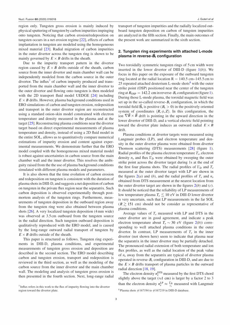
Radial profiles of tungsten gross erosion flux were inferred during plasma shots from the measurement of WI emission
at 400.9 nm, and converted into a tungsten neutral flux (gross erosion flux) using SXB coefficients [11]. The measured tung-sten gross erosion flux Γerosion
W is about 0.1% of the incoming flux of main plasma ions ΓD at the outer divertor target (figure 3(a)). It is noticeable that tungsten gross erosion remains significant even at large distance R − Rsep > 3 cm from the separatrix. Uncertainties in estimations of the tungsten neutral (gross erosion) flux displayed in figure 3(a) include effects of the discrepancy of plasma densities measured with LP and DTS. Such effects are however limited because of the ioniz-ation of sputtered tungsten neutrals within the sheath region, where the plasma density strongly varies.
Tungsten deposition was measured between plasma shots in the outboard region adjacent to the tungsten ring using the DiMES system [29], sketched in figure 1. Radial pro-files of W deposition into carbon layer were measured from samples exposed to various numbers of plasma shots, i.e. during various cumulative durations of plasma exposure [26] (figure 3(a)). The tungsten deposited flux inferred from these measurements is about Γdep
W ≈ 5 × 1013 cm−1 s−1, which corresponds to around 1% of the W gross erosion flux measured on the tungsten ring. The W deposition is remarkably localized in the outboard region of DiMES at R > RDiMES ≈ 149 cm, which is at 3.5 cm from the outer edge of the W ring.
Localized carbon deposition on the tungsten ring has been observed near the location of the outer strike point imme-diately after the first plasma shot #167194 of the series of DIII-D plasma shots considered in this paper. A dark carbon deposition stripe remained visible on tungsten tiles during the rest of the experimental campaign (figure 3(c)), while tungsten rings were exposed to several L-mode and H-mode plasma with different outer strike point locations. Figure 3(b) shows the areal density of carbon versus radial location on the tungsten ring. The coverage of carbon was determined from the yield of protons from D(3He,p)4He and 12C(3He,p)14N nuclear reactions, relative to the yield from reference samples with known coverage, using 2.5 MeV 3He [30]. The spatial resolution, determined by the 3He analysis beam spot size, was 1 mm. The location of the peak near 1.4 cm from the inboard edge, at R = 141.9 cm, corresponds to the visible narrow carbon stripe on the tungsten ring.
3. Modeling of carbon and tungsten erosion, transport and redeposition with ERO-D3D
3.1. Reconstruction of plasma conditions
Impurity erosion, transport and redeposition in the outer divertor are modeled with the ERO model [20, 31]. Numerical simulations are performed with ERO-D3D, which is an enhanced high performance computing version of the original ERO code. Effects of anomalous transport on impurity trans-port are negligible in this work, and only collisions of impu-rity with the main plasma ions (D) are taken into account. Impurity-impurity collisions are neglected here, considering the low concentration of tungsten impurities and of carbon
Figure 2. Plasma conditions in the outer divertor measured with LP (light blue circle) and lowest DTS chord (dark blue diamond): (a) ion flux ΓD (b) electron temperature Te and (c) electron density ne. The blue solid lines represent the average values. The light blue line in (c) corresponds to nLP
e described in section 2. The radial locations of the W ring (red) and DiMES (gray) are indicated. It should be noticed that the reliability of LP measurements for low temperature plasma Te <� 10 eV in DIII-D lower divertor is very uncertain, such that LP measurements in the far SOL (R � 151 cm) should not be consider as viable measurements of plasma conditions.
Nucl. Fusion 60 (2020) 016018
J. Guterl et al
5
impurities, in charge states Z � 4+, in the outer divertor region. Ionization and recombination rates for impurities are taken from the ADAS database [32].
Plasma background conditions in the outer divertor used in ERO-D3D are reconstructed with the standard onion skin model embedded in OEDGE [25] within the trace impurity approximation using LP data at the divertor surface and DTS data in plasma. Plasma conditions reconstructed with the onion skin model are used in ERO-D3D for the purpose of quanti-tative comparison with experiments. In particular, impurity processes investigated in this paper take place near the outer divertor target, where the accuracy of the plasma reconstruc-tion with an onion skin model is acceptable compared to usual experimental uncertainties, in contrast with fluid transport models which are constrained by upstream plasma conditions and usually do not match plasma conditions at the divertor targets.
Furthermore, the poloidal and radial electric fields are obtained by estimating the parallel electric field using the electron momentum balance equation, and assuming that the effects of the parallel plasma current are negligible. This assumption is supported by the measurement of the radial pro-file of the ground current jground with the Langmuir probes, which provides an estimate of the parallel current profile at the
target j‖ ≈ jground
sinα, where α = 1.5◦ is the angle of incidence of the magnetic field lines intersecting the outer divertor target. For instance, the peak of the ground current experimentally measured is about jground ≈ 5 × 10⁴ A m−2, whereas the par-allel electric field at the same location numerically calculated when neglecting j‖ in the electron momentum balance equa-tion is about E‖ ≈ 450 V m−1. Using the Spitzer resistivity to estimate the plasma resistivity η (Te ∼ 30 eV), it can be shown that the contribution of the parallel current to the par-allel electric field is negligible (ηj‖ � E‖).
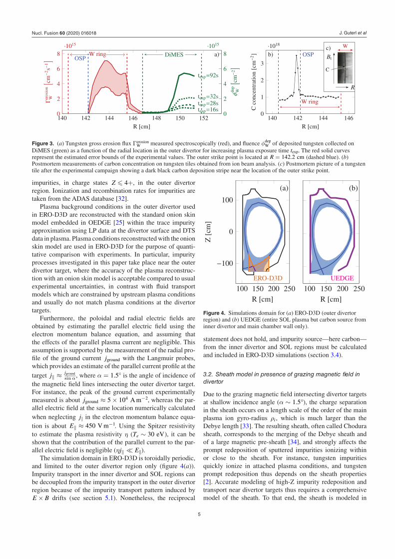
The simulation domain in ERO-D3D is toroidally periodic, and limited to the outer divertor region only (figure 4(a)). Impurity transport in the inner divertor and SOL regions can be decoupled from the impurity transport in the outer divertor region because of the impurity transport pattern induced by E × B drifts (see section 5.1). Nonetheless, the reciprocal
statement does not hold, and impurity source—here carbon—from the inner divertor and SOL regions must be calculated and included in ERO-D3D simulations (section 3.4).
3.2. Sheath model in presence of grazing magnetic field in divertor
Due to the grazing magnetic field intersecting divertor targets at shallow incidence angle (α ∼ 1.5◦), the charge separation in the sheath occurs on a length scale of the order of the main plasma ion gyro-radius ρi , which is much larger than the Debye length [33]. The resulting sheath, often called Chodura sheath, corresponds to the merging of the Debye sheath and of a large magnetic pre-sheath [34], and strongly affects the prompt redeposition of sputtered impurities ionizing within or close to the sheath. For instance, tungsten impurities quickly ionize in attached plasma conditions, and tungsten prompt redeposition thus depends on the sheath properties [2]. Accurate modeling of high-Z impurity redeposition and transport near divertor targets thus requires a comprehensive model of the sheath. To that end, the sheath is modeled in
Figure 3. (a) Tungsten gross erosion flux ΓerosionW measured spectroscopically (red), and fluence φdep
W of deposited tungsten collected on DiMES (green) as a function of the radial location in the outer divertor for increasing plasma exposure time texp. The red solid curves represent the estimated error bounds of the experimental values. The outer strike point is located at R = 142.2 cm (dashed blue). (b) Postmortem measurements of carbon concentration on tungsten tiles obtained from ion beam analysis. (c) Postmortem picture of a tungsten tile after the experimental campaign showing a dark black carbon deposition stripe near the location of the outer strike point.
Figure 4. Simulations domain for (a) ERO-D3D (outer divertor region) and (b) UEDGE (entire SOL plasma but carbon source from inner divertor and main chamber wall only).
Nucl. Fusion 60 (2020) 016018
J. Guterl et al
6
ERO-D3D using the profile of the sheath electric potential ϕ
calculated by Coulette [34] at a magnetic field incidence of 2◦.
This profile is well approximated by ϕ(z) = ∆ϕe−βsheathz
λsheath , where λsheath ≈ 5ρi is the sheath length scale and βsheath = 4. z is the vertical distance from the divertor surface located at z = 0. The variation of the electric potential in the sheath is assumed to be about ∆ϕ ≈ 3Te. The Boltzmann constant is omitted in this paper.
3.3. Homogeneous mixed material model
Interactions between material and plasma particles are described in ERO-D3D with the homogeneous mixed mat-erial (HMM) model [23, 35], which accounts for the effect of impurity mixture in material substrate on sputtering and reflection on material surface. In the HMM model, the impu-rity concentration in PFCs material is assumed to be uniform in a implantation layer of fixed depth. The sputtering yields and the reflection coefficients of species in the implantation layer, e.g. tungsten and carbon in this work, are assumed to be proportional to the concentration of species in the implant-ation layer. The HMM model was shown to well describe the implantation of carbon in tungsten in controlled experiments in linear devices [23]. In the framework of the experiments examined in this paper, carbon and tungsten erosion and rede-position occur mainly in a carbon net erosion regime [22], in which the HMM model is valid. In contrast, the applicability of the HMM model is limited for net deposition of carbon on tungsten [35, 36]. Effects of tungsten surface roughness on impurity erosion and redeposition are ignored in this work, although effects of surface roughness on tungsten sputtering remains unclear in carbon net erosion regime [37].
3.4. Carbon source from inner divertor and main chamber wall
Impurity transport in the inner divertor and SOL regions can be decoupled from the impurity transport in the outer divertor region due to the impurity transport pattern caused by E × B drifts outside of the sheath (see section 5.1). The flux of carbon impurities impinging on the outer divertor target and originating from the inner divertor and from the main chamber wall are calculated using the 2D fluid code UEDGE [24], which uses a fluid model for both neutral and impurity parti-cles. As sketched in the figure 4(b), UEDGE simulations were performed assuming no carbon sputtering in the outer divertor region. Transport coefficients were adjusted in UEDGE to match the ion flux and electron temperature profiles measured with Langmuir probes at the outer divertor target. The use of a 2D plasma fluid model provides a consistent plasma solution in the private flux region (PFR), and allows modeling partially detached plasma in the inner divertor.
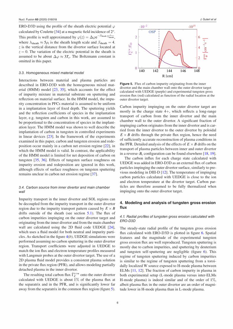
The resulting total carbon flux Γ̂i+wC onto the outer divertor
calculated with UEDGE is about 1% of the plasma flux at the separatrix and in the PFR, and is significantly lower far away from the separatrix in the common flux region (figure 5).
Carbon impurity impinging on the outer divertor target are mostly in the charge state 4+, which reflects a long-range transport of carbon from the inner divertor and the main chamber wall to the outer divertor. A significant fraction of impinging carbon originates from the inner divertor and is car-ried from the inner divertor to the outer divertor by poloidal E × B drifts through the private flux region, hence the need of sufficiently accurate reconstruction of plasma conditions in the PFR. Detailed analysis of the effects of E × B drifts on the transport of plasma particles between inner and outer divertor in a reverse-Bt configuration can be found elsewhere [18, 19].
The carbon influx for each charge state calculated with UEDGE was added in ERO-D3D as an external flux of carbon particles impinging the outer divertor surface, similarly to pre-vious modeling in DIII-D [12]. The temperature of impinging carbon particles calculated with UEDGE is close to the ion and electron temperature at the divertor target. Carbon par-ticles are therefore assumed to be fully thermalized when impinging onto the outer divertor target.
4. Modeling and analysis of tungsten gross erosion flux
4.1. Radial profiles of tungsten gross erosion calculated with ERO-D3D
The steady-state radial profile of the tungsten gross erosion flux calculated with ERO-D3D is plotted in figure 6. Spatial features and the magnitude of the experimental tungsten gross erosion flux are well reproduced. Tungsten sputtering is mostly due to carbon impurities, and sputtering by deuterium and tungsten self-sputtering are negligible (figure 6). This regime of tungsten sputtering induced by carbon impurities is similar to the regime of tungsten sputtering from a toroi-dally localized W source exposed to H-mode plasma between ELMs [11, 12]. The fraction of carbon impurity in plasma in both experimental setup (L-mode plasma versus inter-ELMs H-mode plasma) is indeed similar and of the order of 1%, albeit plasma flux in the outer divertor are an order of magni-tude lower in H-mode plasma than in L-mode plasma.
Figure 5. Flux of carbon impurity originating from the inner divertor and the main chamber wall onto the outer divertor target calculated with UEDGE (purple) and experimental tungsten gross erosion flux (red) calculated as function of the radial location at the outer divertor target.
Nucl. Fusion 60 (2020) 016018

J. Guterl et al
7
The magnitude of the W gross erosion flux remains remark-ably significant far away from the separatrix at R � 143 cm. The flux of carbon impurities from the inner divertor and the main chamber wall is however significantly lower at this radial location (Γ̂i+w
C � 0.1%). This suggests that carbon impurities inducing tungsten sputtering in the common flux region are radially transported in the outer divertor across the tungsten ring, as described in the next section. Because of the radial migration of carbon impurities across the tungsten surface toward the far-SOL, which drive carbon content away from the tungsten ring, effects of the initial carbon concentration in tungsten on the steady flux of carbon impurities onto tungsten are negligible. Therefore, no carbon was assumed to be ini-tially present in tungsten, although the tungsten ring was pre-viously exposed to two plasma shots comparable to the ones examined in this paper.
4.2. Radial carbon transport across tungsten near divertor targets
The flux of carbon impurity eroded and redeposited in the outer divertor region is plotted as a function of the radial location in figure 7(a). The radial asymmetry in the outward direction represents the effective radial transport of carbon impurities across the outer divertor (figure 7(a)). This effec-tive radial transport is characterized by a radial migration scale length of the order of 8 millimeters in the CFR near the separatrix, and strongly contrasts with the very weak radial transport of tungsten (figure 7(b)).
The outboard radial transport of carbon shown in figure 7(a) is mainly caused by E × B drifts in the sheath electric field. In the common flux region above the tungsten ring, the ioniz-ation of neutral carbon is slow, and neutral carbon sputtered or reflected are thus ionized far away from the surface (figure 8(a)), i.e. ziz
ρC> 1, where ziz is the vertical neutral carbon ioniz-
ation mean free path and ρC is the carbon impurity gyro-radius Therefore, carbon ions do not promptly redeposit, and flow
either away or toward the surface along the magnetic field lines depending on their initial toroidal velocity and on col-lisions with plasma ions. Carbon impurities flowing away from the surface are usually ionized into higher charge states 2+ and 3+ due to larger residency time in plasma, before redepositing onto surface due to friction with plasma ions. As a result, sputtered carbon impurities enter the sheath and redeposit on the surface in charge states 1+, 2+ and 3+ (figure 8(b)).
In presence of magnetic field lines at grazing incidence, trajectories of charged impurities within the sheath can be either hyperbolic (open orbits) or elliptic (closed orbits) due to the varying electric field in the sheath,. The nature
Figure 6. W gross erosion flux calculated with ERO-D3D (blue) and measured in experiments (red), and contributions of carbon (green), deuterium (purple) and self-sputtering (gray) to tungsten sputtering calculated with ERO-D3D.
Figure 7. Erosion and redeposition flux of carbon impurities (a) and tungsten impurities (b) in the radial direction in ERO-D3D simulations. The deposition of carbon corresponds to carbon impurities redeposited and effectively implanted in material, and does not include carbon influx from the inner divertor and main chamber wall. The tungsten ring location is indicated by the red lines and the separatrix location by the dashed blue line. The dashed black lines are drawn to guide the eyes.
Figure 8. (a) Average vertical ionization mean-free path ziz over impurity gyro-radius ρC for carbon impurities in ERO-D3D simulations. (b) Stacked plot of carbon influx per charge state on divertor surface emitted and redeposited in the outer divertor region in ERO-D3D simulations. (c) Values of σ for carbon and tungsten impurities as a function of the impurity charge Z.
Nucl. Fusion 60 (2020) 016018

J. Guterl et al
8
of the trajectories of impurities of charge Z and mass M are
determined by the value of σ = ∆ϕ12
MZ λ2
sheathω2c (see appendix),
where ∆ϕ ≈ 3Te is the variation of the electric potential in the sheath and ωc is the impurity cyclotron frequency. The probability that impurities are deflected away from the sur-face within the sheath increases as σ decreases, and therefore the residency time of impurities within the sheath increases as σ decreases (see appendix). The magnitude of the radial E × B drift transport of impurities in the sheath region is proportional to the residency time of these particles in this region. Impurities residing longer in the sheath thus experi-ence stronger radial E × B drift transport within the sheath. This radial E × B drift transport thus increases as σ decreases. In the magnetic configuration considered in this paper where Bt > 0 (figure 1), radial E × B drift induced by the sheath electric field are oriented in the outboard radial direction, as the sheath electric field is pointing toward the divertor surface. When the toroidal magnetic field is reversed, carbon impuri-ties are radially transported inward by the radial E × B drift in the sheath (figure 9(c)).
To emphasize the role of the radial E × B drift in the sheath region on radial carbon impurity transport, simplified ERO-D3D simulations were performed assuming no electric field out of the sheath, no impurity cross-field transport, no impurity reflection on surface and no radial magnetic field. The radial carbon impurity transport resulting from these simulations is plotted in figure 9(a), showing that the radial transport of carbon impurities is localized and of the order of 8 mm. The carbon radial transport is dramatically reduced when the sheath width λsheath is significantly decreased (figure 9(b)), as the impurity residency time in the sheath region diminishes as the sheath is thinner. Whereas the role of the Chodura sheath in redeposition of high-Z impurities is well documented [2, 38–40], the strong dependency of the radial low-Z impurity transport on λsheath indicates that accurate estimations of λsheath must be also considered when mod-eling low-Z impurity radial transport near divertor targets, as noticed previously by Ding et al [12].
Values of σ for carbon impurities are plotted in figure 8(c), showing that σ < 1 for carbon impurities in high charge states Z � 2+, whereas σ > 1 singly charged carbon impurities. It should be noticed that σ does not depend on Te when Ti = Te, and is thus uniform across the tungsten ring. As a consequence, radial impurity transport due to radial E × B drift in the sheath region is more pronounced for C2+ and C3+ than for C+1. The radial transport of carbon impurities is thus reduced when the charge state of carbon impurities is limited to a single charge figure 9(d). In contrast, the radial transport of carbon impuri-ties is only weakly affected when the charge state of carbon impurities is limited to 2+ (figure 9(e)), due to weaker varia-tions of σ as the charge state increases (σ ∼ Z−1). Likewise, the very weak radial transport of tungsten impurities (figure 7(b)) results from the large values of σ for tungsten impurities (figure 8(c)), which mostly redeposit in charge states below 6+ in the considered plasma conditions due to the fast ioniz-ation of tungsten impurities in attached plasma conditions.
Radial carbon impurity transport is broadened and its aniso tropy is reduced when radially isotropic processes such as cross-field transport and reflection are included in simula-tions, as underlined by the differences between radial carbon transport from complete ERO-D3D simulations (figure 7(a)) and from simplified ERO-D3D simulations (figure 9(a)). The importance of the sheath electric field in carbon radial impu-rity transport near divertor target and the reduction of the radial transport anisotropy by cross-field transport have been previously observed when modeling redeposition of puffed methane molecules in similar plasma conditions [12]. As the mass and charge of methane and methyl ions are comparable to carbon mass and charge, and thus have similar values of σ, effects of radial E × B drift within the sheath region on radial impurity transport are expected to be comparable for injected methane and for redeposited carbon.
Poloidal and radial electric fields outside of the sheath region are included in ERO-D3D simulations but are sig-nificantly lower than the sheath electric field (section 5.1). Effects of radial and poloidal E × B drifts outside of the sheath on radial carbon impurities transport near divertor
Figure 9. Erosion and redeposition flux of carbon impurities in the radial direction obtained with simplified ERO-D3D simulations with no electric field out of the sheath, no impurity cross-field transport, no impurity reflection on surface and no radial magnetic field (a). Erosion and redeposition flux of carbon from similar simulations are also plotted when assuming a reduced sheath width (b), an opposite orientation of the toroidal magnetic field (c), and a maximum charge state of carbon impurities limited to 1+ (d) and 2+ (e). The deposition of carbon corresponds to carbon impurities redeposited and effectively implanted in material, and does not include carbon flux from the inner divertor and main chamber wall. The tungsten ring location is indicated by the red lines and the separatrix location by the dashed blue lines. The color map in this figure differs from the color map in figures 7 and 10 to enhance the color contrast.
Nucl. Fusion 60 (2020) 016018

J. Guterl et al
9
targets is therefore small compared to the effects of radial E × B drift in the sheath, as illustrated in figures 10(c)–(e). These figures show the carbon radial transport obtained from ERO-D3D simulations with and without radial and poloidal E × B drifts and using a shorter Chodura sheath.
4.3. Enhancement of effective carbon radial transport due to carbon recycling on tungsten
Carbon impurities are carried across the tungsten ring by radial E × B drift in the sheath region from the separatrix region, where the carbon influx from the inner divertor and main chamber wall is maximum, toward the far-SOL region. The flux of redeposited carbon impurity is noticeably larger near the tungsten ring outer edge than the flux of redeposited impurities at the separatrix (figure 7(a)). Moreover, no other carbon source from the outer divertor region provides a suf-ficiently large carbon influx to induce significant tungsten ero-sion (figure 10(a)). Carbon impurities are thus accumulated onto the tungsten surface.
This accumulation is caused by the implantation of carbon impurity in the tungsten substrate. Schematically, the net flux of carbon impurities impinging on tungsten surface Γinflux
C is the sum of the flux of carbon impurities onto tungsten surface coming from the inner divertor and the main chamber wall Γi+w
C and of the flux of carbon eroding and redepositing in the outer divertor Γredep
C ≈ fredepΓerosionC , where fredep is the fraction
of carbon locally redeposited on tungsten (0 < fredep < 1).
ΓinfluxC = Γredep
C + Γi+wC . (1)
Note that effects of carbon reflection on tungsten are not included in the expression 1 for simplicity, and are discussed thereafter. When the carbon concentration in tungsten reaches its equilibrium, Γinflux
C ≈ ΓerosionC , and therefore
ΓinfluxC ≈
Γi+wC
1 − fredep> Γi+w
C . (2)
The relationship (2) shows that the net influx of carbon on tungsten can be larger than the source of carbon eroded elsewhere than from tungsten surface and transported onto tungsten because of the erosion and redeposition of carbon on tungsten ( fredep > 0). This process of carbon accumulation on tungsten due to erosion and redeposition of carbon impuri-ties on tungsten can be interpreted as the recycling of carbon on tungsten, by analogy with the recycling of main plasma ions on PFCs. The implantation and re-erosion of carbon in tungsten allows the recycling of carbon on tungsten, and thus a large effective carbon influx onto tungsten and significant tungsten erosion. The carbon influx from main chamber wall and inner divertor on tungsten is indeed too small to induce significant tungsten erosion (figure 10(b)).
Nevertheless, the implantation of carbon in tungsten also reduces the sputtering of tungsten. In the HMM model, this effect is modeled assuming that tungsten sputtering is propor-tional to the fraction of tungsten particles in the implantation layer. The two competing effects of carbon implantation in tungsten and of the influx of carbon impinging on tungsten on the sputtering of tungsten result in a weak dependency of the tungsten gross erosion flux on the carbon source. This relationship is illustrated by the slow variation of the tung-sten gross erosion flux as a function of the carbon influx from inner divertor and main chamber wall, which was uniformly rescaled in ERO-D3D simulations (figure 11(a)).
The weak dependency of the tungsten gross erosion flux on the influx from main chamber wall and inner divertor on tung-sten can be roughly reproduced by a semi-analytical expres-sion derived from the HMM model assuming equilibrium of the carbon concentration in tungsten and including reflection of carbon on tungsten:
Figure 10. Radial profiles of the tungsten gross erosion flux (upper plots) and carbon erosion and redeposition flux (lower plots) simulated with ERO-D3D assuming (a) no carbon source from inner divertor and main chamber wall, (b) no carbon implantation in tungsten, (c) no electric fields outside of the sheath, (d) reduced sheath width and (e) reduced sheath width and no electric fields outside of the sheath. Green lines representing tungsten gross erosion fluxes in the top plots correspond to erosion and redeposition fluxes in the bottom plots. Blue lines and red areas in the top plots correspond to simulated and experimental tungsten gross erosion fluxes reported in figures 3(a) and 6 .
Nucl. Fusion 60 (2020) 016018

J. Guterl et al
10
⟨Γ̂erosion
w
⟩≈
YC→W(1 − fC)(
fredepYD→CfC +⟨Γ̂i+w
C
⟩)
1 − fredep(RC→W
(1 − fC
)+YC→CfC
) (3)
⟨Γ̂erosion
W
⟩ and
⟨Γ̂i+w
C
⟩ are the tungsten gross flux and the
carbon influx from inner divertor and main chamber wall normalized by the plasma flux ΓD and averaged across the tungsten ring in respectively the common flux region and near the separatrix. The fraction fredep of eroded carbon impuri-ties redepositing on tungsten in equation (3) is numerically estimated from ERO-D3D simulations. Values of the average sputtering yields Yi→j and of the reflection coefficient RC→W of carbon on tungsten are estimated using the ERO-D3D sput-tering yield and reflection database. The derivation of a self-consistent expression for the fraction fC of carbon implanted in tungsten is possible but cumbersome [22], and average values of fC in the common flux region are inferred from ERO-D3D simulations for simplicity. fC increases monotoni-cally as Γi+w
C increases (figure 11(a)), thus reducing tungsten erosion (blue term in equation (3)). Meanwhile, the increase of Γi+w
C leads to higher carbon influx on tungsten due to recy-cling (green terms in equation (3)), thus increasing tungsten erosion.
4.4. Experimental measurements of carbon plasma content above tungsten
The carbon content above the tungsten ring was measured during the experiments in DIII-D via spectroscopic mea-surements in the UV range [41]. The field of view of the UV spectro meter covered only the tungsten ring. CII line at 388.8nm was identified, and CII emissions calculated with ERO-D3D using the ADAS database are in good agreement with experimental observations (figure 12).
In the attached plasma conditions considered in this work, the CII line emission is mainly produced by the flux of carbon neutrals recycled on W ring. Considering the toroidally sym-metric nature of the W ring and thus the absence of carbon source at the radial location of the tungsten ring, the good reproduction of the CII emission with ERO-D3D indicates that carbon erosion, transport and redeposition on tungsten is well enough reproduced within the modeling framework described in this paper.
4.5. Effects of impurity reflection on tungsten erosion
In attached plasma conditions considered in this work, reflection of carbon impurity on tungsten is large (RC→W ∼ 0.7 − 0.8). Carbon impurities reflected onto the tungsten surface collide with material particles in the near-surface, and thus induce sputtering of tungsten and carbon implanted in tungsten. Because reflected carbon impurities are not implanted in the material, carbon reflection on tungsten can be viewed as equivalent to the deposition of carbon parti-cles in tungsten followed by the immediate re-erosion of those particles. Carbon reflection on tungsten thus constitutes a very efficient way to erode tungsten material, as reflected carbon impurities carry the same kinetic energy than carbon impuri-ties implanted in tungsten but without diluting the tungsten content beneath the surface. The effect of carbon reflection on tungsten on tungsten erosion are shown in figure 11(b), where the gross erosion flux of tungsten increases with the reflection
Figure 11. (a) Average tungsten gross flux on the W ring in the common flux region as a function of the average influx of carbon from the inner divertor and the main chamber wall onto the outer divertor target near the separatrix calculated with ERO-D3D (blue marks) and with the semi-analytic expression (3) (red line). Fluxes are normalized by the plasma flux. The evolution of the concentration of carbon in tungsten fC is also shown (green dots). (b)
⟨Γ̄erosion
W
⟩ as a function of the average reflection coefficient
〈RC→W〉 of carbon on tungsten in the common flux region calculated with ERO-D3D. Dashed lines indicate ERO-D3D results with nominal values of Γi+w
C and RC→W.
Figure 12. CII emission at 388.8 nm calculated with ERO-D3D, and corresponding experimental spectroscopic measurements (square mark). CII emission are collected within a cylindrical field of view of diameter 3.3 cm vertically centered at R = 1.4275 cm (blue rectangle).
Nucl. Fusion 60 (2020) 016018

J. Guterl et al
11
coefficient of carbon on tungsten. Tungsten gross erosion is noticeably reduced by a factor of two in absence of carbon reflection on tungsten.
4.6. Dynamics of carbon radial transport in the outer divertor
The implantation and erosion of carbon into tungsten material is a dynamics process described by the homogeneous mixed material model [23]. The time evolution of the tungsten gross erosion flux and of carbon erosion and deposition is displayed in figure 13(a). Due to the interplay between carbon recycling on tungsten and the radial outboard transport of carbon impu-rities, carbon is progressively accumulated across the tungsten ring, as indicated by the evolution of the radial profile of the fraction of carbon implanted in tungsten (figure 13(b)). In the HMM model, the time scale τimp of the dynamical impurity implantation process depends on the depth of the implantation layer ∆ (τimp ∼ ∆) [22]. ∆ = 2 nm is chosen in this work, in reasonable agreement with the implantation depth of carbon in tungsten calculated with the binary-collision approximation code SDTRIM.SP [42] in similar plasma conditions. Within this assumption, the tungsten gross erosion flux is close to its steady-state value after t = 1 s (figure 13), which is less than the duration of a plasma shot in DIII-D (t ≈ 5 s).
The increase of the tungsten gross erosion flux in time is faster than the increase of the concentration fC of carbon in tungsten because of the non-linear dependency of the tung-sten gross erosion on fC (equation (3)) resulting from the competing effects on tungsten erosion of carbon implant-ation and of carbon recycling. The experimental observation of the evolution in time of the tungsten erosion flux is virtu-ally impossible due to the ramping-up and ramping down of
plasma, which occur in DIII-D on a time scale comparable to τimp ∼ 1 s.
The steady-state radial profile of carbon concentration in tungsten simulated with ERO-D3D plotted in figure 13(b) suggests a net deposition of carbon on tungsten in the private flux region ( fC(R < 142cm) ∼ 1), and may correspond to the net deposition of carbon on tungsten experimentally observed near the separatrix. However, the carbon deposition exper-imentally observed is localized within a ∼4 mm wide stripe. Such discrepancy is expected since the HMM model used in this work is only applicable to model net erosion regime of carbon implantation in tungsten [35, 36], and is only valid to describe the evolution of the carbon concentration in tungsten while fC < 0.9. The peak of the transient radial profile of the carbon concentration in tungsten near the separatrix location (black lines in figure 13(b)) however suggests a localized accumulation of carbon near the separatrix, where the flux of carbon from the inner divertor and the main chamber wall is large (figure 5).
4.7. Robustness of the W gross erosion estimations
Uncertainties in the modeling of erosion, transport and rede-position of impurity in the divertor can be separated between uncertainties in processes related to material physics (sput-tering and implantation), processes related to impurity inter-acting with plasma (ionization, transport and sheath) and plasma conditions. For instance, empirical or numerical models for sputtering yields and implantation can be rela-tively well constrained with dedicated experiments, e.g. in linear machines [23, 43]. In contrast, information on plasma conditions and impurities in plasma are sparse, as plasma and
Figure 13. Dynamic evolution of radial profiles of the tungsten gross erosion flux (a), of the carbon concentration in tungsten (b), and of carbon erosion and redeposition across the tungsten ring (c) simulated with ERO-D3D. The blue and black lines in (a) and (b) correspond to steady-state and transient profiles, respectively.
Nucl. Fusion 60 (2020) 016018

J. Guterl et al
12
impurity diagnostics available in tokamak SOL are limited. For example, the content of carbon in charge state 4+ and higher is not diagnosed in the divertor region in DIII-D, and only emission of carbon in lower charges state are usually mea-sured. Carbon in lower charge states are however essentially carbon sputtered from the nearby divertor target, and virtually no information is available about higher charge state carbon (Z � 4+) flowing from the SOL into the divertor region.
Plasma conditions near the outer divertor target can be nev-ertheless sufficiently well diagnosed via LP and DTS measure-ments. Accordingly, the source of carbon coming from the inner divertor and the main chamber wall and flowing onto the outer divertor target remains the larger uncertainty in the present modeling of carbon erosion and redeposition. Effects of uncer-tainties in carbon source on tungsten gross erosion are how-ever mitigated due to the interplay between the increase of the tungsten sputtering with the carbon influx on tungsten, and the reduction of tungsten sputtering due to the increase of the frac-tion of carbon implanted in tungsten discussed in section 4.3. This feature is intrinsic to the implantation of low-Z impurity in tungsten, and therefore explains why modeling of tung-sten gross erosion in tokamak divertor usually provides good agreement with experimental measurements in various plasma conditions [8, 11, 44], despite large uncertainties on low-Z impurity source. The modeling of tungsten erosion presented in this paper therefore appears very robust against uncertainties in carbon source from inner divertor and main chamber wall.
5. Long-range migration of impurities in the outer divertor due to E × B drifts
5.1. Impurity radial transport due to interplay between radial and poloidal E × B drifts
In the reverse-Bt configuration, a strong poloidal E × B drift is pointing upward in the common flux region and
downward in the private flux region, and radial E × B drifts are pointing in the outward direction in the common and private flux regions (figure 14(a)). The radial and poloidal electric fields Erad and Epol outside of the sheath are nevertheless much smaller than the sheath electric field Esheath ∼ 3Te
λsheath∼ 105 V m−1. Consequently, the carbon radial
transport near the outer divertor surface due to E × B drifts outside of the sheath is small compared to the radial transport induced by radial E × B drift within the sheath region (figures 10(c)–(e)). Carbon radial transport due to E × B drifts outside of the sheath in the outer divertor region has therefore limited effects on tungsten gross erosion, as illustrated in figure 10(c).
E × B drifts outside of the sheath have nevertheless sig-nificant effects on long-range impurity radial transport in the outer divertor region. Particles poloidally drifting upward are simultaneously drifting radially in the outward direction due to the radial E × B drift, and redeposit on material due to friction with main plasma ions. Such effects of E × B drifts outside of the sheath on long-range radial carbon transport are illustrated by carbon trajectories plotted in figures 14(b) and (c). The radial E × B drift of particles is enhanced by the interplay with the poloidal E × B drift, as the poloidal E × B drift extends the flying time of impurities in plasma by car-rying them away from the surface. Effects of long-range radial carbon transport due to E × B drifts outside of the sheath on tungsten gross erosion are illustrated by the slight reduction of the tungsten gross erosion near the outer edge of the tungsten ring when Erad = Epol = 0. The decrease of the tungsten gross erosion is due to the increase of the carbon influx on tungsten induced by the reduction of the radial transport outside of the sheath.
As a result of the long-range transport of carbon impurities in the outer divertor region induced by E × B drifts outside of the sheath, virtually no carbon impurity flows outside of the outer divertor region into the SOL or the inner divertor region. This long-range impurity transport pattern in the outer divertor
Figure 14. (a) Radial and poloidal electric fields in the outer divertor region. (b), (c) Trajectories of carbon (black) and tungsten (red) particles eroded from the tungsten ring and normalized erosion and deposition flux of tungsten particles as a function of the radial location in the outer divertor target calculated with ERO-D3D with E × B drifts outside the sheath (b) and without E × B drifts outside the sheath (c). DiMES edges are indicated by the green lines and tungsten ring edges by the red lines.
Nucl. Fusion 60 (2020) 016018

J. Guterl et al
13
region therefore allows modeling of the carbon source in the main wall chamber and inner divertor independently from the carbon source in the outer divertor region.
5.2. Radial migration and deposition of tungsten on carbon in the outer divertor
As described in section 2, the tungsten deposition flux exper-imentally estimated by collecting deposited tungsten par-ticles on DiMES (146.5 cm < R < 151.5 cm) corresponds to only a small fraction (∼1%) of the tungsten gross erosion flux from the tungsten ring (140.5 cm < R < 145.5 cm). Additionally, the measured tungsten deposition is very local-ized at R > 149 cm, 3.5 cm away from the outer edge of the tungsten ring. The localized nature of the tungsten deposition can be well reproduced with ERO-D3D using plasma back-ground conditions calculated with UEDGE (section 3.4), as illustrated in figure 14(b). Estimations of the radial electric field and of the resulting poloidal E × B drift with the onion skin model are indeed very sensitive to any variations in the radial profile of experimental temperature and density mea-sured at the divertor target. Because of inherent fluctuations of LP and DTS measurements, uncertainties in quantitative esti-mations of the radial electric field with the onion skin model are large. In contrast, radial electric fields calculated with UEDGE exhibit much smoother radial variations.
The long-range radial transport of impurities in the outer divertor region induced by E × B drifts outside of the sheath is similar for tungsten and carbon impurities, since E × B drift velocities do not depend on the impurity mass. Similarly to the long-range transport of carbon impurities in the outer divertor, tungsten particles are carried away from the tungsten surface along the magnetic field lines by the poloidal E × B drift, and simultaneously transported in the radial outward direction across the magnetic field lines by the radial E × B drift. As the magnitude of the E × B drifts diminish away from the separatrix, tungsten particles are then transported along the magnetic field lines toward the divertor target due to the friction with the main plasma ions, as illustrated by trajecto-ries of tungsten impurities plotted in figure 14(b). Differences in trajectories of carbon and tungsten impurities are due the larger inertia of tungsten impurities, which flow further away from the surface. The long-range impurity transport in the outer divertor region induced by E × B drifts outside of the sheath modeled and analyzed in this paper is consistent with experimental observations and modeling of impurity transport in other tokamaks [5, 44–46].
As indicated by the tungsten erosion and redeposition pattern in figure 14(b), almost all tungsten particles which do not redeposit locally are redeposited in the outboard region at R > 149 cm. In contrast, tungsten impurities only redeposit in the vicinity of their sputtering location when Erad = Epol = 0 (figure 14(c)). This non-local transport pat-tern of tungsten impurities in the outer divertor region exper-imentally observed and predicted with ERO-D3D suggests that the experimental setup described in this paper may pro-vide direct experimental insights into tungsten net erosion and
mechanisms governing it, e.g. tungsten prompt redeposition within and near the sheath region.
It should be noticed that tungsten source and deposition fluxes in figure 14(b) are normalized to unity, and that the tungsten deposited flux in the outer region away from the tungsten ring is about 10% of the tungsten erosion flux, which is an order of magnitude higher than the tungsten deposition flux inferred from experimental measurements (figure 3(b)). This discrepancy is not surprising considering that tungsten neutrals are mainly ionized within the sheath or close to the entrance of the sheath. Consequently, uncertainties in the small fraction of tungsten impurities which do not promptly redeposit and are actually transported into the plasma beyond the sheath region are therefore large, considering uncertain-ties in tungsten ionization rates, sheath and plasma divertor conditions.
Because of those numerous uncertainties, modeling tung-sten net erosion can be significantly more complex than mod-eling tungsten gross erosion, although tungsten net erosion is far more important for future fusion reactors. Although sim-ulations reproducing a fraction of 1% of tungsten migrating from the tungsten ring to the outer region can be performed by adjusting plasma and sheath parameters, such simulations are of little interest here. Contrariwise, other measurements of tungsten deposition with similar plasma settings but dif-ferent values of plasma density and temperature in the divertor region may allow to quantitatively examine sheath and plasma processes governing tungsten net erosion.
6. Conclusions and outlook
Two tungsten rings were inserted in the lower divertor of DIII-D, and 25 repeated attached L-mode plasma shots in the reverse-Bt configuration were performed with the outer strike point located on the outboard tungsten ring. The modeling and analysis of these experiments were conducted using the ERO model [20, 31], and numerical simulations were per-formed with ERO-D3D. Plasma conditions and E × B drifts used in ERO-D3D were reconstructed with a standard onion-skin model using experimental measurements of plasma con-ditions from LP and DTS [25]. The 2D fluid code UEDGE [24] was also used to model plasma conditions and carbon impurities from the inner divertor and the main chamber wall and flowing onto the outer divertor target. This carbon source was then introduced in ERO-D3D as a carbon impurity flux external to the outer divertor region. The effects of carbon implantation in tungsten were modeled with the homogeneous mixed material model [23, 31].
The radial profile of the tungsten gross erosion flux exper-imentally inferred in situ from spectroscopic measurements of the WI line (400.9 nm) can be well reproduced with ERO-D3D. Tungsten gross erosion is mainly induced by carbon impurity impinging onto tungsten with very little contrib ution from tungsten self-sputtering and tungsten sputtering by main plasma ion (deuterium). Radial impurity transport of carbon impurities in the outer divertor near the divertor surface is shown to be mainly governed by radial E × B drift in the
Nucl. Fusion 60 (2020) 016018

J. Guterl et al
14
sheath, and to depend on the carbon charge state. Impurity radial transport due to radial E × B drift in the sheath is a consequence of the large width of the Chodura sheath, formed by the Debye sheath and a large magnetic pre-sheath, due to grazing magnetic fields at the divertor target.
The effective flux of carbon radially transported is enhanced by the large amount of carbon impurity implanted and re-eroded in tungsten. Erosion and redeposition of carbon in tungsten can be described as a carbon recycling process, by analogy with the well-known recycling of main plasma ions on PFCs. The recycling of carbon on tungsten increases the effective flux of carbon impinging on tungsten, and therefore enhances tungsten sputtering. The large reflection of carbon impurities on tungsten increases carbon recycling and thus tungsten erosion. Besides, the gross erosion flux of tungsten is shown to weakly depend on the magnitude of the carbon source from inner divertor and main chamber wall because of competing effects of carbon implantation in tungsten which reduces tungsten erosion and carbon recycling which increases tungsten erosion. The dynamics of carbon implant-ation in tungsten is shown to be compatible with the plasma shot duration in DIII-D
Carbon impurities are carried away from the divertor target along the magnetic field line due to poloidal E × B drift out-side of the sheath, which increases the flying time of impurity in the plasma and thus enhances the effects of radial E × B drift outside of the sheath on long-range radial transport of impurities. In comparison with carbon radial transport due to radial E × B drift in the sheath, long-rang radial transport of carbon due to E × B drifts outside of the sheath is small, and weakly affects tungsten gross erosion.
The analysis and modeling of tungsten deposition observed in the far-SOL on DiMES during DIII-D experiments suggest that tungsten radial migration is mainly induced by E × B drifts outside of the sheath, similarly to long-range carbon radial transport in the outer divertor. Most of tungsten parti-cles which do not locally redeposit migrate and redeposit in the far-SOL region. The experimental framework described in this paper—a toroidally symmetric localized source of tungsten surrounded by graphite PFCs in the outer divertor of DIII-D in the reverse-Bt configuration—may be used to obtain physics insights into tungsten net erosion in divertor.
The modeling and analysis of tungsten gross erosion pre-sented in this paper illustrates the variety of physics processes (ionization, sheath, E × B drifts, impurity collisions with plasma particles, mixed-material effects, reflection of impu-rity on material) and their synergistic effects, e.g. carbon recy-cling, which must be taken into account to accurately model erosion, transport and redeposition of impurities in tokamak divertor. Results presented here also highlight the necessity of consistently modeling plasma conditions, electric fields and resulting E × B drifts inside and outside the sheath to accurately predict impurity transport and subsequent material erosion. Moreover, this work underlines the importance of a comprehensive sheath model in integrated modeling of impu-rity erosion, transport and redeposition [47] to account for the radial transport of low-Z impurities near divertor surface due
to radial E × B drift in the sheath, and to accurately predict tungsten erosion, e.g. in ITER divertor.
Finally, the present work illustrates how the introduction of toroidally symmetric tungsten sources radially localized in the outer divertor, which strongly contrast with the sur-rounding sources of low-Z impurities (here carbon), allows the discrimination between local and non-local impurity ero-sion and redeposition, and thus the experimental characteriza-tion of impurity transport pattern in tokamak divertor. Such an experimental setup might be used to characterize impurity production and transport in divertor plasma configurations relevant for future fusion reactors, for instance partially or fully detached plasma, for which impurity transport driven by E × B drifts may play an important role [19].
Acknowledgments
This material is based upon work supported by the U.S. Department of Energy, Office of Science, Office of Fusion Energy Sciences, using the DIII-D National Fusion Facility, a DOE Office of Science user facility, under Awards DE-FC02-04ER54698 and DE-SC0018423. DIII-D data shown in this paper can be obtained in digital format by following the links at https://fusion.gat.com/global/D3D_DMP.
Disclaimer
This report was prepared as an account of work sponsored by an agency of the United States Government. Neither the United States Government nor any agency thereof, nor any of their employees, makes any warranty, express or implied, or assumes any legal liability or responsibility for the acc-uracy, completeness, or usefulness of any information, appa-ratus, product, or process disclosed, or represents that its use would not infringe privately owned rights. Reference herein to any specific commercial product, process, or service by trade name, trademark, manufacturer, or otherwise does not neces-sarily constitute or imply its endorsement, recommendation, or favoring by the United States Government or any agency thereof. The views and opinions of authors expressed herein do not necessarily state or reflect those of the United States Government or any agency thereof.
Appendix
As noted by Cohen and Ryutov in their analysis of charged particles trajectories in a Chodura sheath formed by the Debye sheath and a large magnetic pre-sheath [48], the vertical motion of the guiding center of the particles is slow due to the grazing incidence of the magnetic field lines. Two types of par-
ticle trajectories can be identified depending on σ = ∆ϕ12
MZ λ2
sheathω2c.
∆ϕ ≈ 3Te is the variation of the electric potential in the sheath.
Z, M and ωc are the mass, the charge and the cyclotron fre-quency of the particle, and λsheath is the sheath length scale. σ does not depend on Te when Ti = Te.
Although the equations of motion of a charged particle in a Chodura sheath are fully integrable, no analytic solution is
Nucl. Fusion 60 (2020) 016018

J. Guterl et al
15
available when considering a non-linear sheath electric field. Nevertheless, the effective potential energy of a charged par-ticle derived by Cohen and Ryutov [48] can be used to deter-mine whether a particle, which enters the sheath at z = λsheath, will be deflected away from the surface as a function of the normalized cross-field velocity of the particle v̂⊥ = v⊥
ωcλsheath
and of the angle of the incidence of the particle velocity
θin = sin−1(
v̂Rv̂⊥
), where v̂R is the radial velocity of the par-
ticle. The minimum values θminin of θin at which particle must
penetrate the sheath to be deflected away from the surface are plotted in figure A1 as a function of ̂v⊥ for various values of σ corresponding to C1+ , C2+ and C3+ .
The cross-field kinetic energy E⊥ of carbon sputtered in the common flux region is of the order of E⊥ ∼ Eb, where Eb ≈ 7.4eV is the binding energy of carbon on graphite sur-face, and of the order of E⊥ ∼ Te once carbon impurities are thermalized, with Te ∼ 30eV in the common flux region (figure 2). The cross-field velocity of carbon impurities above the tungsten ring in the common flux region is thus of the order of v̂⊥ ∼ 0.25 − 0.6. Values of θmin
in corresponding to this range of velocity are displayed in figure A1, showing that C1+ impurities complete a smaller number of partial gyration orbits in the sheath before hitting the material surface than C2+ and C3+ impurities. The residency time of C1+ impurities in the sheath is thus lower than the residency time of C2+ and C3+ impurities in the sheath. The radial transport of carbon impurities due to radial E × B drift within the sheath region is consequently stronger for C2+ and C3+ impurities than for C1+ impurities, as illustrated in figures 9(d) and (e).
ORCID iDs
J. Guterl https://orcid.org/0000-0002-1049-3094D. Rudakov https://orcid.org/0000-0002-5266-4269W.R. Wampler https://orcid.org/0000-0002-4263-252XP. Snyder https://orcid.org/0000-0002-0613-4232
References
[1] Pitts R. et al 2013 A full tungsten divertor for ITER: physics issues and design status J. Nucl. Mater. 438 S48–56
[2] Brooks J.N. 1990 Near-surface sputtered particle transport for an oblique incidence magnetic field plasma Phys. Fluids 2 1858–63
[3] Neu R. 1996 The tungsten divertor experiment at ASDEX upgrade Plasma Phys. Control. Fusion 38 165–79
[4] Krieger K., Roth J., Annen A., Jacob W., Pitcher C.S., Schneider W., Thoma A. and Weinlich M. 1997 Study of gross and net erosion in the ASDEX upgrade divertor J. Nucl. Mater. 241–243 684–9
[5] Ueda Y. et al 2009 Localized tungsten deposition in divertor region in JT-60U Nucl. Fusion 49 065027
[6] Mayer M., Likonen J., Coad J.P., Maier H., Balden M., Lindig S., Vainonen-Ahlgren E. and Philipps V. 2007 Tungsten erosion in the outer divertor of JET J. Nucl. Mater. 363–365 101–6
[7] Brezinsek S. 2015 Plasma-surface interaction in the Be/W environment: conclusions drawn from the JET-ILW for ITER J. Nucl. Mater. 463 11–21
[8] Xie H., Ding R., Kirschner A., Chen J.L., Ding F., Mao H.M., Feng W., Borodin D. and Wang L. 2017 ERO modelling of tungsten erosion and re-deposition in EAST L mode discharges Phys. Plasmas 24 092512
[9] Thoma A., Asmussen K., Dux R., Krieger K., Herrmann A., Napiontek B., Neu R., Steinbrink J., Weinlich M., Wenzel U. and The ASDEX Upgrade Team 1997 Spectroscopic measurements of tungsten erosion in the ASDEX upgrade divertor Plasma Phys. Control. Fusion 39 1487–99
[10] Laengner M., Brezinsek S., Coenen J.W., Pospieszczyk A., Kondratyev D., Borodin D., Stoschus H., Schmitz O., Philipps V. and Samm U. 2013 Penetration depths of injected/sputtered tungsten in the plasma edge layer of TEXTOR J. Nucl. Mater. 438 865–70
[11] Abrams T. et al 2017 The inter-ELM tungsten erosion profile in DIII-D H-mode discharges and benchmarking with ERO+OEDGE modeling Nucl. Fusion 57 056034
[12] Ding R. et al 2017 Advances in understanding of high-Z material erosion and re-deposition in low-Z wall environment in DIII-D Nucl. Fusion 57 056016
[13] Rudakov D.L. et al 2014 Net versus gross erosion of high-Z materials in the divertor of DIII-D Phys. Scr. T 159 014030
[14] Mayer M., Rohde V., Ramos G., Vainonen-Ahlgren E., Likonen J. and Chen J.L. 2007 Erosion of tungsten and carbon markers in the outer divertor of ASDEX-Upgrade Phys. Scr. T 128 106–10
[15] Hakola A. et al 2014 Long-term erosion of plasma-facing materials with different surface roughness in ASDEX Upgrade Phys. Scr. T 159 014027
[16] Holtrop K., Buchenauer D., Chrobak C., Murphy C., Nygren R., Unterberg E. and Zach M. 2017 The design and use of tungsten coated TZM molybdenum tile inserts in the DIII-D tokamak divertor Fusion Sci. Technol. 72 634–9
[17] Xu G., Guterl J., Abrams T., Wang H., Zhang P., Elder J., Unterberg E., Thomas D., Guo H. and Ye M. 2019 Study of DIII-D tungsten erosion processes by using a carbon–tungsten mixed material model Nucl. Mater. Energy 18 141–6
[18] Boedo J.A., Schaffer M.J., Maingi R. and Lasnier C.J. 2000 Electric field-induced plasma convection in tokamak divertors Phys. Plasmas 7 1075–8
[19] Jaervinen A.E. et al 2017 Interpretations of the impact of cross-field drifts on divertor flows in DIII-D with UEDGE Nucl. Mater. Energy 12 1136–40
[20] Kögler U. and Winter J. 1997 ERO-TEXTOR: 3D Monte-Carlo code for local impurity modeling in the scrape-off layer of TEXTOR Technical Report Julich Report
[21] Kirschner A., Philipps V., Winter J. and Kögler U. 2000 Simulation of the plasma-wall interaction in a tokamak
Figure A1. Minimal angle of incidence θminin at which charged
particles must enter the sheath to be deflected away from the surface as a function of the cross-field particle velocity v̂⊥.
Nucl. Fusion 60 (2020) 016018
J. Guterl et al
16
with the Monte Carlo code ERO-TEXTOR Nucl. Fusion 40 989–1001
[22] Guterl J., Abrams T., Ding R., Guo H.Y., Rudakov D. and Wampler W. 2017 Dynamic control of low-Z material deposition and tungsten erosion by strike point sweeping on DIII-D Nucl. Mater. Energy 12 392–8
[23] Krieger K. and Roth J. 2001 Synergistic effects by simultaneous bombardment of tungsten with hydrogen and carbon J. Nucl. Mater. 290–3 107–11
[24] Rognlien T.D. et al 2000 User Manual for the UEDGE edge-plasma transport code Technical Report Lawrence Livermore National Laboratory
[25] Stangeby P.C. et al 2003 Interpretive modeling of simple-as-possible-plasma discharges on DIII-D using the OEDGE code J. Nucl. Mater. 313–316 883–7
[26] Wampler W.R., Rudakov D.L., Watkins J.G., McLean A.G., Unterberg E.A. and Stangeby P.C. 2017 Measurements of tungsten migration in the DIII-D divertor Phys. Scr. T 170 014041
[27] Xu G., Guterl J., Abrams T., Wang H.Q., Elder J.D., Unterberg E., Thomas D.M., Stangeby P.C., Guo H. and Ye M. 2019 Modeling of inter- and intra-ELM tungsten erosion during DIII-D H-mode discharges Nucl. Fusion 59 126018
[28] Carlstrom T.N. et al 1992 Design and operation of the multipulse Thomson scattering diagnostic on DIII-D Rev. Sci. Instrum. 63 4901–6
[29] Wong C., Whyte D., Bastasz R., Brooks J., West W. and Wampler W. 1998 Divertor materials evaluation system (DiMES) J. Nucl. Mater. 258–63 433–9
[30] Tesmer J.R. and Nastasi M. 1995 Handbook of Modern Ion Beam Materials Analysis (Pittsburgh, PA: Materials Research Society)
[31] Kirschner A., Tskhakaya D., Kawamura G., Borodin D., Brezinsek S., Ding R., Linsmeier C. and Romazanov J. 2016 Modelling of impurity transport and plasma-wall interaction in fusion devices with the ERO code: basics of the code and examples of application Contrib. Plasma Phys. 56 622–7
[32] Summers H.P. 2004 The ADAS User Manual version 2.6 (www.adas.ac.uk/manual.php)
[33] Chodura R. 1982 Plasma-wall transition in an oblique magnetic field Phys. Fluids 25 1628
[34] Coulette D. and Manfredi G. 2016 Kinetic simulations of the Chodura and Debye sheaths for magnetic fields with grazing incidence Plasma Phys. Control. Fusion 58 025008
[35] Droste S., Kirschner A., Borodin D., Kreter A., Brezinsek S., Philipps V., Samm U. and Schmitz O. 2007 Modelling of
13CH4 injection experiments with graphite and tungsten test limiters in TEXTOR using the coupled code ERO-SDTrimSP Plasma Phys. Control. Fusion 50 015006
[36] Kirschner A., Borodin D., Philipps V., Samm U., Ding R., Schmid K., Roth J., Kukushkin A., Federici G. and Loarte A. 2009 Estimations of erosion fluxes, material deposition and tritium retention in the divertor of ITER J. Nucl. Mater. 390–1 152–5
[37] Kreter A. et al 2008 Effect of surface roughness and substrate material on carbon erosion and deposition in the TEXTOR tokamak Plasma Phys. Control. Fusion 50 095008
[38] Chankin A.V., Coster D. and Dux R. 2014 Monte Carlo simulations of tungsten redeposition at the divertor target Plasma Phys. Control. Fusion 56 025003
[39] Ding R. et al 2015 Simulation of gross and net erosion of high-Zmaterials in the DIII-D divertor Nucl. Fusion 56 016021
[40] Tskhakaya D. and Groth M. 2015 Modelling of tungsten re-deposition coefficient J. Nucl. Mater. 463 624–8
[41] Johnson C.A. et al 2019 Advances in neutral tungsten ultraviolet spectroscopy for the potential benefit to erosion diagnosis Plasma Phys. Control. Fusion 61 095006
[42] Eckstein W. 2013 Computer Simulation of Ion-Solid Interactions vol 10 (Berlin: Springer)
[43] Behrisch R. and Eckstein W. 2007 Sputtering by Particle Bombardment and Computer Calculations from Threshold to MeV Energies vol 110 (Berlin: Springer)
[44] Hakola A., Airila M.I., Mellet N., Groth M., Karhunen J., Kurki-Suonio T., Makkonen T., Sillanpää H., Meisl G. and Oberkofler M. 2017 ERO and PIC simulations of gross and net erosion of tungsten in the outer strike-point region of ASDEX upgrade Nucl. Mater. Energy 12 423–8
[45] Aho-Mantila L. et al 2011 Effect of E × B driven transport on the deposition of carbon in the outer divertor of ASDEX upgrade J. Nucl. Mater. 415 231–4
[46]Weckmann A., Petersson P., Rubel M., Wienhold P., Brezinsek S., Coenen J.W., Kirschner A., Kreter A. and Pospieszczyk A. 2016 Local migration studies of high-Z metals in the TEXTOR tokamak Phys. Scr. T 167 014058
[47] Lasa A. et al Integrated plasma material modeling of the evolution of tungsten divertor surfaces during He-only and burning plasma discharges in ITER Nucl. Fusion submitted
[48] Cohen R.H. and Ryutov D.D. 1998 Particle trajectories in a sheath in a strongly tilted magnetic field Phys. Plasmas 5 808–17
Nucl. Fusion 60 (2020) 016018