ernest 0. lawrence radiation laboratory147057/datastream... · oscillator-anode supply voltage in...
TRANSCRIPT

IDRL 37.01-Rev. :) cy 2
Cy~ l
University of California
Ernest 0. Radiation
Lawrence laboratory
TWO-WEEK LOAN COPY
This is a library Circulating Copy which may be borrowed for two weeks. For a personal retention copy. call Tech. Info. Diuision, Ext. 5545
Berkeley, California

DISCLAIMER
This document was prepared as an account of work sponsored by the United States Government. While this document is believed to contain correct information, neither the United States Government nor any agency thereof, nor the Regents of the University of California, nor any of their employees, makes any warranty, express or implied, or assumes any legal responsibility for the accuracy, completeness, or usefulness of any information, apparatus, product, or process disclosed, or represents that its use would not infringe privately owned rights. Reference herein to any specific commercial product, process, or service by its trade name, trademark, manufacturer, or otherwise, does not necessarily constitute or imply its endorsement, recommendation, or favoring by the United States Government or any agency thereof, or the Regents of the University of California. The views and opinions of authors expressed herein do not necessarily state or reflect those of the United States Government or any agency thereof or the Regents of the University of California.

{!· I ... ·. J· .···
.[iool
UNIVERSITY OF CALIFORNIA
· Radiation Laboratory Berkeley, California
·contract No. W -7405-eng-48
UCRL-3701 Rev:
THE FAULT DIVERTER-A PROTECTIVE DEVICE FOR HIGH-POWER ELECTRON TUBES
Bob H. Smith
August, 1957
\._
I /
Printed for the U.S. Atomic Energy Commission

..
'-i
-2- UCRL-3701 Rev
THE FAULT DIVERTER-A PROTECTIVE DEVICE FOR HIGH-POWER ELECTRON TUBES
Bob H. Smith
Radiation Laboratory University of California
Berkeley, California
August, 1957
ABSTRACT
Fault diverters, or crowbars, have proven to be very effective protection against transient-induced power arcs within accelerator oscillator tubes. This device short circuits the oscillator-plate power supply in the event of an over-current, thus removing the power flow from the fault within a few microseconds. · Ignitrons, thyratrons, and triggered spark gaps are used for this purpose. The power supply is protected from the short circ'uit either by a current-limiting device or a high- speed contactor which removes the system from the power lines within a few milliseconds. The paper describes the fault diverters, and associated circuitry, used on several of the accelerators in Berkeley and Livermore.

-·
-3:- UCRL-3701 R~v
THE FAULT DIVERTER-A PROTECTIVE DEVICE FOR HIGH-POWER ELECTRON TUBES
Bob H. Smith
Radiation Laboratory University of California
Berkeley, California
August, 1957
INTRODUCTION
Vacuum tubes used to excite the resonators of particle accelerators are subjected to severe high-voltage transient ini~iated by resonator sparks. These transients produce power arcs which may have magnitudes of hundreds of ampere and, if allowed to persist, are capable of destroying the oscillator tube.
The protective device that is employed on aq of the UCRL afcelerators is the fault directer (crowbar) first developed by M. V. Hoover. This consists of an ignitron, thyratron, or spark gap that short-circuits the oscillator-anode supply voltage in the event of an over current, thus transferring the fault.from the delicate oscillator tube to the rugged crowbar. The time interval between the initial fault and its diversion to the crowbar is sufficiently short (a few microseconds) to present ~ppreciable energy trans-
,'fer to the oscillator tube.
EQUIPMENT AND OPERATION
A typical power supply with ignitron crowbar is $hown in Fig. 1. Threephase 60-cycle power is fed through an ignitron contactor to the plate trans-
> former and rectifier and hence through a filter to the load. In the event of a fault condition in the loag, the ignitron crowbar is fired, short- circuiting the power supply and preventing further power flow into the load. A second signal from the fault-detector is sent to open the ignitron cont~ctor before sufficient power flows into the power supply to do any damage. The time required to fire the crowbar a:fter detection of a fault is between one and ten microseconds- -the former a rather fast crowbar and the latter, rather slow. The time required to open the ignitron contactor is always le$s than eight milliseconds--the time to the next current zero in the power lines.
The basic components of an ignitron crowbar are shown in Fig. 2. The purpose of the 2-ohm resistor in the anode circuit is to provide sufficient anode potential on the crowbar to permit firing under short- circuit load conditions. The resistance value assumes that this crowbar is intended to fire at about 50 amperes, which provides 100 vat the anode. The 0.25-henry choke limits the power supply current after the crowbar has been
1 . M.V. Hoover, U.S~ Patent 2, 615, 147, Oct. 21, 1952.

3¢ ··r· <DO rv
POWER
-4- UCRL- 370 l Rev.
LOAD
FAULT DETECTOR ~------J
TYPICAL POWER5UPPLY WITH FAULT DIVERTER (CROWBAR)
MU -1.3940
Fig. 1. Typical power supply with fault diverter (crowbar).

•
-5- UCRL-370,1 Rev.
--'lf .2.5 H
TO I G N I T E f< TO !="IRING' CONTACTOR
CIRCUITRY
BASIC IGNITRON FAULT DIVERTER (CRO\N'BAR)
TO
LOAD
MU -13941
Fig. 2. Basic components of a fault diverter .

'··::.·
-6- UCRL-3701 Rev
fired until the contactor can be opened. The holding anode may be used to prevent the arc from being extinguished in the event the positive buss should ring, as is.often the case. Overlooking this condition is one of the most frequent errors in crowbar design. lt is possible to' omit the holding .. anode by locating the 1-mfd capacitor and 25-ohm resistor near the anode so as to minimize the inductance in this circuit. This capacitor and re sistor also speed up the anode arc. The current transformer in the cathode of the crowbar opens the contactor in the event that the crowbar itself sparks over.
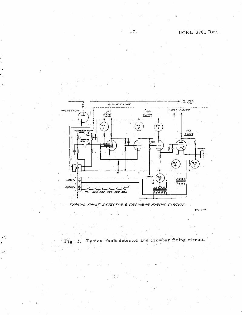
Fi,gure 3 shows a typical fault detector. An overcurrent is detected by means of the magnetron- -typically a G. E. type 2B23. The coil in the d. c. high-voltage line usually consists of about 5 turns and surrounds the magnetron. The coil is designed so that excessive current provides sufficient magnetic field to cut off the electron flow in the magnetron, permitting the grid of V- 1 to rise to positive' 300 v. This trips the Schmit trigger consisting of V-1 and the first half of V-2 which fires the thy.rati'-ori, V-3, 'discharging the capacitor into the ignitor of the crowbar, The current trip adjustment typically provides about a five-to-one range of currents required to cut off the magnitron.
The relays are employed to provide a fail- safe feature. Each cathode in V -1 and V- 2 must be emitting in order to close the interlock chain and keep the machine in operation. A pentagrid tube is used for the first half of the Schmit trigger which is normally not conducting. Because grid number one is maintaine
1d at zero bias, current flows through the number 2
screengrid but not thr~ough number 4, the current normally being cut-off by the control gird number 3. Relay number 4 insures that the filament of the thyratron is continuous, Re 5 insures that it has plate voltage, and Re 6 insures that there are no cathode-to-filament shorts. We have found that the use of 1500 von the thyratron speeds up the firing of the crowbar.
The power supply for the 90-in. cyclotron at Livermore (Fig. 4) consists of an ignitron crowbar, surge network, lOOo/o buck-or-boost induCtion regulator, and two three-phase full-wave rectifiers connected in series. to produce 20 kv. Because one power transformer is connected delta-delta while the other is co'nnected delta-wye, the ripple is 12-phase rather than 6-phase. The reason that we prefer two stacked 10-kv rectifiers is that we have found type-857 rectifiers to be somewhat marginal when operated at 20-kv.
The transformers connected between the 2400-v line and the ignitron pu!se chassis are potential transformers used for phasing the ignitors. The chassis employs an electronic gate which interrupts the ignitor firing upon receiving a signal from the fault detector.
The surge network is a rather large unit and prevents the snap-out current (about 3 amp) of the ignitrons from producing a transient by means of the magnetizing inductance of the induction regulator. The snap- out current drops to zero within -one fJ.Sec. Further transient protection is provided by the Westinghouse autovalves and the thyrite connected across the powertransformer secondaries. Control of transients is the key to satisfactory
· ignitron performance and should be carefully considered.
•
-7- UCRL-3701 Rev.
u L>.c; #.Y,/../N£
MU-1394l
Fig .. 3. Typical fault detector and crowbar firl.ng circuit.
-·'

-8- UCRL-3701 Rev.
r• fjKAt. A•Uhilt A-~
')o~v
'l6A c:w.
M\l-1:19·13
Fig. 4. 500-KW power supply and crowbar of 90-inch cyclotron at Livermore.

• ""·•'
··.<" .....
-9- UCRL-3701 Rev
Figure 5 shows the surge-network cabinet, the induction regulator, and the two 300-kva plate transformers of the power supply of the 90-in~ cyclotron.
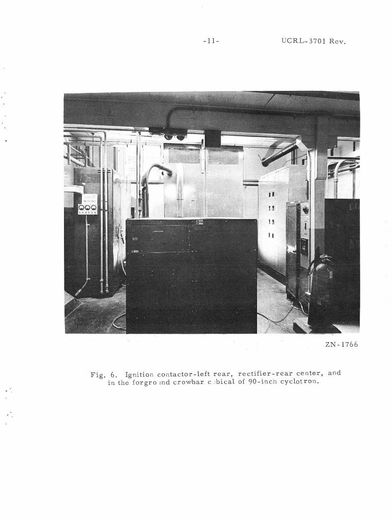
The rectifier room of this machine is shown in Fig. 6. To the left is the ignitron contactor cabinet, rear center is the rectifier cab~net, and in the foreground is the filter and crowbar cabinet. The type GL 5779 .is used as the crowbar. While this tube is only rated at 350 v in rectifier service·, it operates'a,t 20 kv in crowbar service without the slightest difficulty. In each crowbar oper'ation the energy 'dissipated is only 83 w- sec. When the hig}fvoltage buss is shortci:rcuited with a ground hook only a slight "click" is heard- -about equal to the discharge of a 10 rhfd; capacitor charged t'o 300 v --because most of the current is discharged through the crowbar.
Figure·. 7 shows one phase of the ignitron contactor of the 90-in. cyclotron. A pai.r of type 5555 ignitrons are used in each line.
Figure 8 shows the 9-,M W power supply of the A- 48 linear accelerator at Livermore which is fed by a 110-kv to 13.8-kv line transfqrmer (Fig. 9). A motor-generato"t" set (.,Vic~ 10) is used to isolate the oower supply frbm the line. This ac::celerator sometimes operates·:Under pulsed conditions nec:i.r' 18_ MW with a duty factor of 50%, and the m.,.g set filters the pulse from the main pow-er Line.
This power supply does not use an ignitron contactor but uses an ignitron rectifier. The two- plate transformer.s are shown in Figure 11. ·After a crowbar operation, the firing of the' ignitors is stopped. Probably the choice of the ·large _ignitrons .as· c:rowba:r s on this power supply was governed by the desirability Of maintaining only one type of spare rather than by power considerations. ·
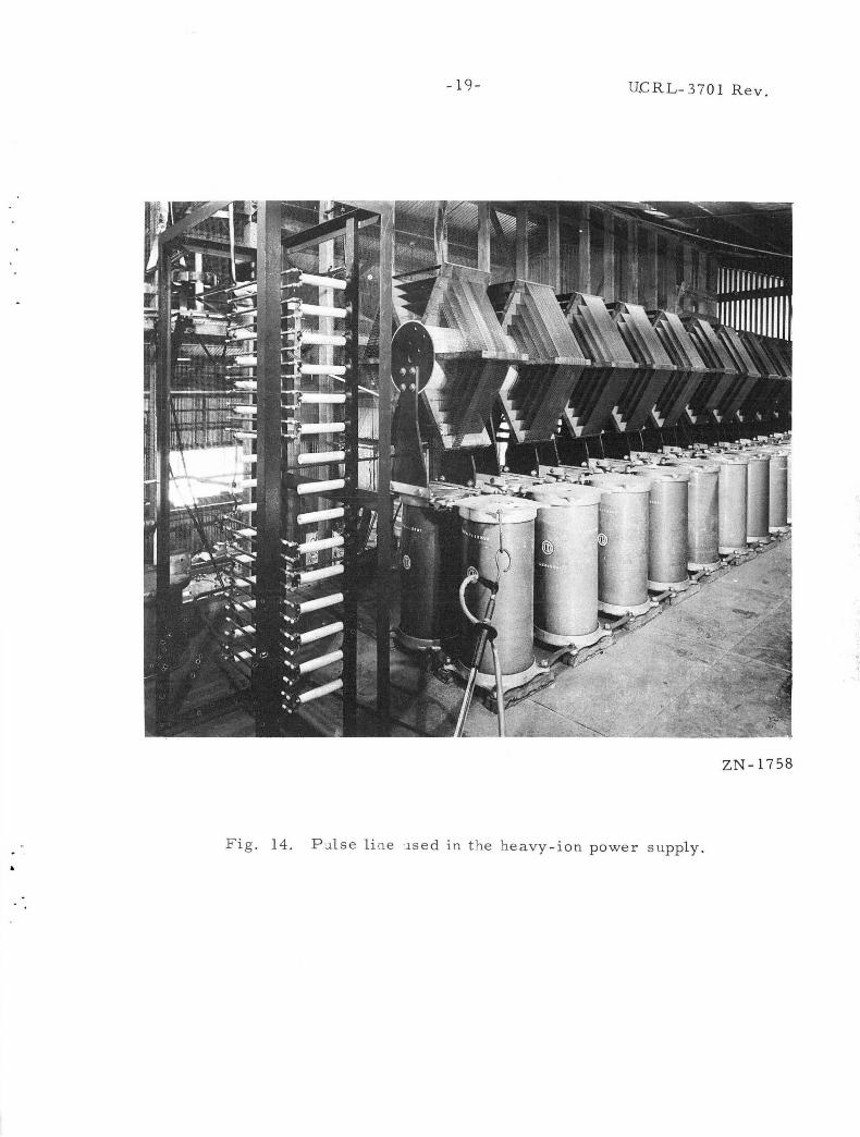
The power supply of the heavy-ion accelerator at Berkeley is shown. in Fig. 12. It was chose!! to illustrate a pulsed system. Figure 13 shows the power transformers and 56 2 rectifiers of the heavy ion mach:j.ne. Type 56 2 tubes are used in an emission-limited arrangement to charge the pulse line (Fig. 14) to 40 kv. The pulse line is discharged into the oscillator by means of a triggered spark gap (Fig. 15). In the event of a fault a secbnd gap serves as a crowbar to divert the remaining energy in the pulse line. Because the inductances in series with the spark gaps saturate at a relatively low current they are effectively removed during the main pulse of current. During the initial firing of the gap, howevyr, they permit the cathode end of the gap to be depressed to about -100 kv by the trigger to insure the firing of the gap. Because the oscillator approximately p)atches the line, it receives only about half of the voltage to which the line was charged. The spark gaps probably will be replaced with ignitrons in the near future as ignitrons are regarded as being more reliable.
Figure 16 shows the crowbar installation of the Bevatron. ground is the current-limiting c:Qoke, spark gap, and thyrite. back and to the right, the 5779 crowbar can be seen.
In the foreFurther

-10- UCRL-3701 Rev.
Fig. 5. Pla t e transformers and i nd ·-1ction r e g ulator of t h e 90-inch cyclotron power s ·.1pply .
ZN-1767

•
-9- UCRL-3701 Rev
Figure 5 shows the surge- network cabinet, the induction regulator, and the two 300-kva plate transformers of the power supply of the 90-in. cyclotron.
The rectifier room of this machine is shown in Fig . 6 . To the left is the ignitron contactor cabinet, rear center is the rectifier cab~net, and in the foreground is the filter and crowbar cabinet. The type GL 5779 is used as the crowbar . While this tube is only rated at 350 v in rectifier service, it operates at 20 kv in crowbar service without the slightest difficulty . In each crowbar operation the energy dissipated is only 83 w- sec . When the highvoltage buss is shortcircuited with a ground hook only a slight "click" is heard- -about equal to the discharge of a 10 mfd . capacitor charged t'o 300 v --because most of the current is discharged through the crowbar .
Figure 7 shows one phase of the ignitron contactor of the 90-in. cyclotron . A pair of type 5555 ignitrons are used in each line.
Figure 8 shows the 9-MW power supply of the A-48 linear accelerator at Livermore which is fed by a 1l0-kv to 13 .8-kv line transfQrmer (Fig. 9) . A motor-generator set (_f'iP' . 10) is used to isolate the oower supply from the line. This accelerator sometimes operates under pulsed conditions near· 18, MW with a duty factor of 50o/o, and the m-g set filters the pulse from the main power line.
This power supply does not use an ignitron contactor but uses an ignitron rectifier. The two- plate trap.sformer.s are shown in Figure 11 . After a crowbar operation, the firing of the ignitors is stopped. Probably the choice of the large ignitrons as crowbars on this power supply was governed by the desirability of maintaining only one type of spare rather than by power considerations.
The power supply of the heavy-ion accelerator at Berkeley is shown in Fig. 12. It was chosen to illustrate a pulsed system. Figure 13 shows the power transformers and 562 rectifiers of the heavy ion mach:j.ne. Type 562 tubes are used in an emission-limited arrangement to charge the pulse line (Fig . 14) to 40 kv. The pulse line is discharged into the oscillator by means of a triggered spark gap (Fig . 15 ). In the event of a fault a second gap serves as a crowbar to divert the remaining energy in the pulse line. Because the inductances in series with the spark gaps saturate at a relatively low current they are effectively removed during the main pulse of current. During the initial firing of the gap, however, they permit the cathode end of the gap to be depressed to about -100 kv by the trigger to insure the firing of the gap . Because the oscillator approximately matches the line, it receives only about half of the voltage to which the line was charged. The spark gaps probably will be replaced with ignitrons in the near future as ignitrons are regarded as being more reliable .
Figure 16 shows the crowbar installation of the Bevatron. In the foreground is the current-limiting choke, spark gap, and thyrite. Further back and to the right, the 5779 crowbar can be seen.
- ll- UCRL-3701 R ev.
ZN-1766
Fig. 6. Ignitio n co ntactor-left rear, rectifier-rear center, and i n the forgro md crowbar c ,bical of 90-incn cyclotron.

-12-UCRL-3701 Rev.
ZN-1765
Fig. 7. Construction details of one phase of ignition contactor of 90-inch cyclotron.

9MEE.AWATT POWER SUPPLY OF A~8 LIHEAR ACCELERATOR
AI LIVEII.MORE
-13-
R(tl l " '£ R lVP( SOC.
IC.N ITA Ot-1$ -~. fl'r-i··A
,..,,
C 10'0 W ij4U
,V Pf '0"
UCRL- 3 70 l R ev.
· ···~ --\.Wu ___ --+
20ICV
cw
MU - 1.3 94 ·1
Fig. 8. 9-MW power supply of A-43 linear accelerator at Livermore.

-14- UCRL-3701 Rev.
ZN-1762
Fig. 9. 110-KV to 13.8-KV transformer of A-48 linear accelerator.
'v

-15- UCRL-37 01 Rev.
ZN-1764
Fig. 10. Motor - generator set of A-48 linear accelerator.

-16- UCRL-3701 Rev.
ZN-1763
Fig. 11. Plate transformers of A-48 linear accelerator.

-1 7 -
I /t:l SEC. + _z- S EC.
TYPE 5~Z ~---.
UCRL- 37 0 1 R~v .
7R/66EREO 5/"',t~,e~ tMP
+
7't7 ? ?IL.S/ IY'.r CM?-CVIT /CJ tJ5c.
2C.t:V
'-------v--·--1
T,/?/ 6-6-E.e'ED :5P~A!K 6-AP
@ / 50 ,1.
,?t/L.SE L INE /33 .JL A"E?. R/ITE -= /t7/5~C-
/ t7 C£'t7WLUe
/-/R//11'6- £/RCt//T
8 45/C ? /£CI'I/ CJF A!YCJL.J~ /1JWE.e. .SVr>?L Y I C:ZtJW-:5.-fe.. v/'-· /lt!'.4VY ./CJ/1/ ~C<.t' /c- ~/9/ 'C:Jk:.
MU -13945
Fig. 12. Anode power supply a nd crowbar of h e avy ion line ar accelerator in Berkeley.

-18- UCRL-3701 Rev.
ZN-1760 " I.·
F . 13 Plate transformer of heavy-ion linear accelerator. lg. .
-19- U!::RL-3701 Rev.
ZN-1758
Fig. 14. P ulse li ne ·~se d in t he he avy-ion power supply.

-20- UCRL- 3701 Rev.
Fig. 15. Spark-gap type crowbar for the heavy-ion linear
accelerator.
ZN -1759

-21- UCRL- 3701 R e v .
ZN- 176 1
.. ',
Fig. 16. Bevatron crowbar a n d associated circuitry.

I
I I
This report was prepared as an account of Government sponsored work. Neither the United States, nor the CommiSSion, nor any person acting on behalf of the Commission:
A. Makes any warranty or representation, expressed or implied, with respect to the accuracy, completeness, or usefulness of the information contained in this report, or that the use of any information, apparatus, method, or process disclosed in this report may not infringe privately owned rights; or
B. Assumes any liabilities with respect to the use of, or for damages resulting from the use of any information, apparatus, method, or process disclosed in this report.
As used in the above, "person acting on behalf of the Commission" includes any employee or contractor of the Commission, or employee of such contractor, to the extent that such employee or contractor of the Commission, or employee of such contractor prepares, disseminates, or provides access to, any information pursuant to his employment or contract with the Commission, or his employment with such contractor.
