ericsson 2g optimization crash course
DESCRIPTION
Guideline for Network optimisation in 2G RAN EricssonTRANSCRIPT

RF Optimization Crash Course (Knowledge Sharing)
Prepared by:
Christopher L. Dela Cruz
November 2006

Agenda
Daily Optimization Flow Chart Dropped Calls Handover Performance SDCCH Congestion TCH Congestion DHA and DYMA Features DHA and DYMA Dimensioning Process TRA Pool Dimensioning due to DHA
Reconfiguration Paging Analysis

Daily Optimization Flow ChartCheck BSC KPI Trend
Identify Worst Performing Cells per KPI
Check Cell Level Trend of the Identified Worst Cells
Is the problem global?
Check for BSC/MSC/TRC/
Transmission Level activities or problems
Yes
No
Investigate on possible causes or reason of
degradation
Schedule MRR Recording
ConsistencyCheck of Cell Level
Parameters
Check TRX/TS with high CONERRCNT:
RXMFP
Change the incorrect parameters
Analyze MRR Results and associate them with KPI trends.
Block and De-block TRX with high CONERRCNT.
Escalate the problem to BTS Engineer for on-site
troubleshooting: TRX Swap, VSWR check, Feeder, Antenna
and Connectors check.
Conduct Drivetest if MRR Data is insufficient to identify the
problem. Check for BTS/TRX alarms: ALLIP, RXASP, RXMFP
Clear the Alarm or Escalate the Problem to OMC/BTS Engineers.
Verify the results through Statistics
Problem Solved? ENDYes
No
Escalate the problem to concerned department
Check for any activity on the site such as Upgrades, Antenna Replacements, etc.
Revert the activity or troubleshoot.

Dropped Calls

Dropped calls show the number of abnormal disconnections during call setup or during conversation. From a subscriber point of view, the most serious dropped calls are those that interrupts an ongoing conversation, i.e. a call dropped on the TCH.
There are different counters for dropped calls, i.e. dropped calls due to low signal strength, bad quality, too high timing advance and miscellaneous that will give us indication of the reason for possible bad performance. The mechanisms behind dropped calls on TCH and SDCCH are described below:
1. Radio Link Time-OutEvery time a SACCH message can not be decoded the radio link time-out counter is decreased by 1. If the message can be decoded the counter is incremented by 2. However, the value can not exceed the initial value. The initial value is set by the parameter RLINKT for radio link time-out in the mobile station and by RLINKUP for time-out in the BSC. If the mobile moves out of coverage and no measurement reports are received in the BSC, there will be a radio link time-out and the message Channel Release (cause: abnormal release, unspecified) is sent to the mobile station and the SACCH is deactivated in the BTS. A Clear Request message is sent to the MSC. To be sure that the mobile has stopped transmitting, the BSC now waits RLINKT SACCH periods before the timeslot is released and a new call can be established on the channel.
Dropped Calls (1)

2. Layer 2 Time-OutIf the BTS never get an acknowledge on a Layer 2 message after the time T200XN200, the BTS will send Error Indication (cause: T200 expired) to the BSC, which will send Channel Release (cause: abnormal release, timer expired) to the mobile station and a Clear Request to the MSC. The SACCH is deactivated and the BSC waits RLINKT SACCH periods before the timeslot is released and a new call can use the channel. This is only valid if the call is in steady state, i.e. not during handover or assignment.
3. Release IndicationWhen the BTS received a layer 2 DISC frame from the mobile it replies with a Layer 2 UA frame to the mobile station and a Release Indication to the BSC. The system does only react on Release Indication if it is received during a normal disconnection situation. If such a message is received unexpectedly this will usually cause radio link time-out or timer T200 expiration as the mobile station stops the transmitting of measurement reports. It is also possible that the release will be normal depending on when the Release Indication is received.
Dropped Calls (2)

4. MSC Time-Out
Normal Release:
If the MSC never received a response on a message (e.g. Identity Request) and there is no radio link time-out or layer 2 time-out, the MSC will send a Clear Command to the BSC. The time-out is depending on the message. When receiving Clear Command, the BSC will send a Channel Release (cause: normal release) and then deactivates the SACCH.
Reject (only SDCCH):
If the MSC never receives a response on the first message after Establish Indication, the MSC will send a reject message. If the connection was a Location Update it will be a Location Update Reject (cause: network failure) and if the connection was a mobile originating call (CM Service Request) a CM Service Reject (cause: network failure) will be sent. The MSC will then send a Clear Command to the BSC and the call is cleared by Channel Release (cause: normal release).
5. Assignment to TCHBefore sending an Assignment Command from the BSC at TCH assignment, the following two criterion have to be fulfilled:a. There must be a TCH channel available, i.e. no congestion b. The locating algorithm must have received at least one valid measurement report. If either of the criterion is not fulfilled, Assignment Command will not be sent and a Channel Release (cause: abnormal release, unspecified) will be sent to the mobile station and a Clear Request to the MSC.
Dropped Calls (3)

CONERRCNT is one counter of object type MOTS, which indicates abnormally terminated connections on one time slot and is incremented for TCH and SDCCH when a connection is dropped. The counter CONERRCNT should be used to identify problem device and interference on a certain channel. The counter will identify a TS that have more dropped calls than the average TS.
BADQDLBADQUL
LOWSSDLLOWSSUL
TALIM

Drop Call Rate Analysis

The classification of TCH Drop Reasons are arranged in the order of priority:1.Excessive Timing Advance2.Low Signal Strength3.Bad Quality4.Sudden Loss of Connection5.Other Reasons
Excessive Timing AdvanceThe TCH Drop counters due to Excessive Timing Advance will pegged when the during the time of disconnection, the last Timing Advance value recorded was higher than the TALIM Parameter. This drop reason is commonly apparent to isolated or island sites with a wide coverage area.
Action: Check if the cell parameter TALIM is < 63. Check if the co-channel cells are overshooting.
Solution: Set TALIM to a value close to 63. Tilt antenna/reduce antenna height/output power, etc. for co-channel cells.
TCH Drop Reasons (1)

Low Signal Strength on Down or Uplink or Both LinksThe drops counters due to Low Signal Strength will be pegged when the Signal Strength during the last Measurement Report before the call dropped is below the LOWSSDL and/or LOWSSUL Thresholds. LOWSSDL and LOWSSUL are BSC Exchange Property parameters which is used only for statistics purposes and does not affect the behavior of calls. If both UL and DL Signal Strength are below the thresholds, only Drop due to Low SS BL will pegged.
Normally a call is dropped at the border of large rural cell with insufficient coverage. Bad tunnel coverage cause many dropped calls as well as so called coverage holes. Bad indoor coverage will result in dropped calls. Building shadowing could be another reason.
Action: Check coverage plots. Check output power. Check power balance and link budget. Check if Omni site. Check antenna configuration & type. Check antenna installation.Perform drive tests & site survey.Check TRX/TS with high CONERRCNT. Solution:Add a repeater to increase coverage in for example a tunnel.Change to a better antenna (with higher gain) for the base station.Add a new base station if there are large coverage holes.Block/Deblock TRX
TCH Drop Reasons (2)


Poor Quality on Down or Uplink or Both LinksThe drops counters due to Bad Quality will be pegged when the Signal Strength during the last Measurement Report before the call dropped is above the BADQDL and/or BADQUL Thresholds. BADQDL and BADQUL (expressed in DTQU) are BSC Exchange Property parameters which is used only for statistics purposes and does not affect the behavior of calls. If both UL and DL Quality are above the thresholds, only Drop due to BAD Quality BL will pegged.
Problem on Bad Quality is usually associated with Co-channel Interference on BCCH or TCH. Faulty MAIO assignment can cause frequency collisions on co-sited cells especially on 1x1 Reuse. External interference is also one possible cause of problem on quality.
Action: Check C/I and C/A plots. Check Frequency Plan (Co-BCCH or Co-BSIC Problem).Check MAIO, HOP, HSN parameters.Check FHOP if correctly configured (BB or SY).Check for External Interference.Perform drive tests.Solution: Change BCCH frequency.Change BSIC.Change MAIO, HOP, HSN.Change FHOP.Record RIR or on-site Frequency Scanning to identify source of interference.Use available radio features.
TCH Drop Reasons (3)

Sudden Loss of ConnectionDrops due to Sudden Loss are drops that have not been registered as low signal strength, excessive timing advance, bad quality or hardware (other) reasons, and the locating procedure indicates missing measurement results from the MS.
There are some common scenarios that could lead to Sudden Loss of connections such as very sudden and severe drops in signal strength, such as when subscribers enter into buildings, elevators, parking garages, etc., very sudden and severe occurrence of interference, MS runs out of battery during conversation, Handover Lost, BTS HW faults, Synchronization or A-bis link fault (transmission faults), and MS Faults.
Action: Check BTS Error Logs, Alarms and Fault Codes.Check CONERRCNT per TRX and TS.Check Transmission Link (A-bis).Check for DIP Slips.Check LAPD Congestion.Correlate Handover Lost to Drops due to Sudden LossSolution: Fix Hardware Faults and Alarms.Reset TRX with high CONERRCNT.Ensure that Synchronization and A-bis Link are stable.Change RBLT with high DIP Slips.Change CONFACT or increase Transmission CapacityInvestigate HO Lost Problem
TCH Drop Reasons (4)

TCH Drops due to Other ReasonsTCH drops due to Other Reasons are computed by subtracting the sum of drops due to Excessive TA, Low SS, Bad Quality and Sudden Loss from the Total TCH Drop Counts. Drops due to Other Reasons are generally associated with hardware problems, transmission link problems on A-bis, Ater or A-interfaces, and sometimes Handover Lost.
Action: Check BTS Error Logs.Check Alarms and Fault Codes.Check CONERRCNT per TRX and TS.Check Transmission Link (A-bis).Check for DIP Slips.Correlate Handover Lost to Drops due to Other Reasons
Solution: Fix Hardware Faults and Alarms.Reset TRX with high CONERRCNT.Ensure that Synchronization and A-bis Link are stable.Change RBLT with high DIP Slips.Investigate HO Lost Problem
TCH Drop Reasons (5)

Low Signal Strength on Down or Uplink The reason for poor coverage could be too few sites, wrong output power, shadowing, no indoor coverage or network equipment failure.Action: Check coverage plots.Check output power. Perform drive tests. Check BTS error logSolution: Add new sites. Increase output power. Repair faulty equipment.
Poor Quality on Down or UplinkAction: Check C/I and C/A plots. Check frequency plan. Perform drive tests.Solution: Change frequency. Use available radio features.
Too High Timing AdvanceAction: Check if the cell parameter TALIM is < 63. Check if the co-channel cells are over-heard.Solution: Set TALIM to a value close to 63. Tilt antenna/reduce antenna height/output power, etc. for co-channel cells.
Mobile ErrorSome old mobiles may cause dropped calls if certain radio network features are used. Another reason is that the MS is damaged and not working properly.Action: .Check MS fleet.Solution: Inform operator.
Probable Reasons of Drops on SDCCH (1)

Subscriber BehaviorPoorly educated subscribers could use their handsets incorrectly by not raising antennas, choosing ill-advised locations to attempt calls, etc.Action: Check customer complaints and their MS.
Battery FlawWhen a subscriber runs out of battery during a conversation, the call will be registered as dropped call due to low signal strength or others.Action: Check if MS power regulation is used. Check if DTX uplink is used.
Congestion on TCHThe SDCCH is dropped when congestion on TCH.Action: Check TCH congestionSolution: Increase capacity on TCH or using features like Assignment to another cell, Cell Load Sharing, HCS, Dynamic Half-Rate Allocation and FR-HR Mode Adaptation etc.
Probable Reasons of Drops on SDCCH (2)

Handover Performance

Handover Performance
Handover is a key function in a GSM network. If the handover performance is poor the subscriber will perceive the quality of the network as bad.
Handover performance statistics should preferably be measured on 24 hour data or longer.
The following checks should be performed:
1. Check for handover relations with low traffic (e.g. less than 10% of average number of handovers per relation).2. Check for unbalanced handover relations (e.g. relations which have not approximate the same number of handovers in either direction. Remark: Unbalanced handovers relation indicate problem if measured on whole days, assuming that the same number of people go in and out of the cell coverage area.3. Check if the reason for unbalanced handover is congestion.

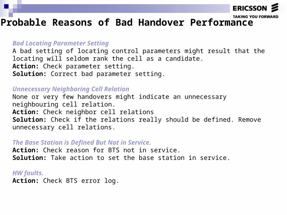
Bad Locating Parameter SettingA bad setting of locating control parameters might result that the locating will seldom rank the cell as a candidate.Action: Check parameter setting.Solution: Correct bad parameter setting.
Unnecessary Neighboring Cell RelationNone or very few handovers might indicate an unnecessary neighbouring cell relation.Action: Check neighbor cell relationsSolution: Check if the relations really should be defined. Remove unnecessary cell relations.
The Base Station is Defined But Not in Service.Action: Check reason for BTS not in service.Solution: Take action to set the base station in service.
HW faults.Action: Check BTS error log.
Probable Reasons of Bad Handover Performance

Missed measurement frequencies in BA-listThis will cause no handover decisions to the target cell.Action: Check measurement frequencies list.Solution: Add missed frequencies.
Permitted Network Color Code problemIf NCCPERM doesn’t include neighboring cell’s NCC, there will be no handovers.Action: Check NCCPERM.Solution: Add NCC of neighbors to NCCPERM.
Wrong Use of HCSAction: Check HCS related parametersSolution: Change to normal value.
Poor inter-MSC/BSC handover performanceIf the cell is at the border of inter-BSC or inter-MSC, poor inter-MSC/BSC handover performance will cause few or no handover attempts.Action: Check inter-MSC/BSC handover performance
Probable Reasons of Bad Handover Performance

Unsuccessful Handovers
There can be two reasons why an attempt is counted as unsuccessful: either the mobile station was lost or the call was reverted to the old cell and channel.Unsuccessful handover may lead to a dropped call. Investigate if there is any difference between incoming and outgoing handovers. This can give further reasons of the problem area.
The lost handovers are registered at outgoing handover. Note that also dropped call counters are stepped.

CongestionA high congestion might lead to dragged calls (handover performed at a not intended location) and a lot of unsuccessful handovers.Action: Check TCH congestion.Solution: Add more TCH capacity. Activate DHA or DYMA.
Timer Expire After MS is LostThe MS never answers the base station.Action: Check coverage. Check interference.
Link Connection or HW FailureAction: Check BTS error log. Perform site visit. Perform link performance measurements.Solution: Repair faulty equipment.
Bad Antenna Installation Action: Perform site survey and check antenna installation. Check antenna cabling.Solution: Adjust antenna installation, antenna type or cabling.
Antennas Connected to Wrong Feeder Action: Perform site survey and check antenna installation. Check antenna cabling.Solution: Correct the antenna to the right sector.
Incorrect Down Tilt Action: Perform site survey and check antenna installation.Solution: Correct antenna tilting.
Probable Reasons of Bad Handover Performance

The MS Measures Signal Strength of Another Co- or Adjacent than Presumed. Action: Check frequency plan..Perform drive tests.Solution: Decrease interference. .
Wrong Neighboring Cell is DefinedThis can happen when a new site is added and old definitions are not undefined and new relations are not inserted.Action: Check parameter setting. Run Undefined Neighboring Cell Recording.Solution: Define or remove neighboring cells.
Missing Handover RelationsMissing handover relations will act as coverage holes. Suddenly the MS can not perform handover to the best server (i.e. not in the BA-list), instead a handover is performed to the second best candidate.Action: Check existing handover relations. Check with actual site positions and coverage plots if more relations need to be added. Run Undefined Neighboring Cell Recording.Solution: Add missing handover relations.
Wrong Output Power due to Faulty Transceiver Action: Check output power setting. Check BTS error log
Wrong Locating Parameter SettingAction: Check locating parameters Solution: Correct parameter setting.
Probable Reasons of Bad Handover Performance

Poor Inter-MSC/BSC Handover PerformanceFor outer or external cell, wrong definitions in either MSC or BSC may be reason for the problem.Action: Check inter-MSC/BSC handover performance.
Many Neighbors Defined Many defined measurement frequencies defined (>16) will decrease the accuracy of the mobile measurements to locate the best six servers. Many measurement frequencies mean few samples per frequency and problem formobiles to decode the BSIC.Action: Check number of definitions.Solution: Remove unnecessary definitions.
Too Many Measurement Channels DefinedAction: Check number of measurement channelsSolution: Remove unnecessary measurement channels.
Bad Use of Radio Network FeaturesIncorrect use of radio features such as Dynamic Power Control, Locating, Intra-Cell Handover, Frequency Hopping, etc.Action: Check Feature parameter setting.Solution: Correct strange and erroneous parameter setting.
Delayed Handover DecisionA delayed handover decision can be due to congestion in the target cell.Action: Check handover parameters.
Probable Reasons of Bad Handover Performance

Bad Radio CoverageAction: Check coverage plots.
High Interference, Co-Channel or AdjacentThe potential handover candidate is disturbed by interference. Outgoing handover due to bad uplink quality may indicate interference from co-channel another MS. On the border, the quality may be rather bad and the signal strength low. Bad downlink quality may indicate interference from another co-channel base station.Action: Check interference. Check if many handovers are performed due to downlink or uplink bad quality.Solution: Change frequency plan.
Lower Output Power on TCH than on the BCCH in the Target Cell Action: Check output power. Check BSTXPWR and BSPWR definition
Not good neighboring cell relation Action:. Delete the relation if not necessary.
Receiver Antenna Problem or RBS HW problems (in candidate cell) Action: . Check antenna installation. Check RBS HW and Error log of the target cell
Probable Reasons of Bad Handover Performance

SDCCH Congestion

SDCCH Congestion

Low AvailabilityAction: Check SDCCH Availability. Check if the channels are manual, control or automatic blocked.Solution: Change and repair faulty equipment. Review the O&M procedures.
Increasing Traffic Demand The high traffic could be related to an occasional event or due to a long term growth.Action: Check if short term traffic growth. Make trend comparisons. Check if combined SDCCH is used.Check SDCCH dimensioning.Solution: Increase the number of SDCCH channels. Note, that an increase may lead to the need for new transceivers. If combined SDCCH is used, non-combined channel configuration should be introduced.
Bad use of Adaptive configuration of Logical ChannelsBy using the Adaptive configuration of logical channels feature, the basic SDCCH configuration in a cell will be under-dimensioned. If this feature is not used correctly, it will cause SDCCH congestion.Action: Check if ACSTATE is on. Check parameters related to Adaptive configuration of logical channelsSolution: If ACSTATE is off, it is suggested to switch on.
Long Mean Holding Time If the mean holding time is long, this generates a higher traffic load.Action: Check SDCCH Mean Holding Time
Too Frequent Periodic RegistrationAction: Check Random Access Distribution. Check the timer T3212 in the BSC and the parametersBTDM and GTDM in the MSCSolution: Decrease the periodic registration.
Probable Reasons of SDCCH Congestion

Location Area Border CellIf the cell is situated on a misplaced Location Area border, this means that unnecessary many normal LUs are performed.Action: Check site position and location area border. Check Location Update Performance. Check parameter CRH etc.Solution: If the site is located close to major road or railway, consider to move the Location Area border. Increase the hysteresis CRH. The CRH is the hysteresis value used when the MS in idle mode crosses a LA border. The default value for this parameter is 4. If a high number of Location Updatings occurs in a Location Area border cell, a higher CRH can be set in order to reduce the number of LUs.
Extensive SMS UsageExtensive SMS usage increases the SDCCH traffic and could cause congestion if badly dimensioned SDCCH channels.Action: Check SMS activity.Solution: Re-dimension the SDCCH channels with consideration taken to SMS usage.
Cell Broadcast UsedAction: Check if Cell Broadcast is active. .If active, check if it is used by the operator.Solution: Remove Cell Broadcast if not used.
IMSI Attach/Detach in Use. An introduction of IMSI attach/detach will increase the traffic on SDCCH. However, the benefits are that the paging success rate will increase. The recommendation is to use Attach/Detach.
Cell Software File Congestion Action: Check SAE setting. High Ratio of Random AccessesAction: Check Random Access performance
Probable Reasons of SDCCH Congestion

Congestion on TCH Action: Check TCH Congestion Solution: Increase the TCH capacity.
Congestion on Signaling RoutesAction: Check signaling performance & transmission capacity.Solution: Add more transmission capacity or re-route traffic if possible.
False AccessesNo response from MS after Channel Request. The system waits about 5 seconds before performing a disconnection and the channel is available again.Action: Check frequency plan. Check interference.Solution: Improve frequency plan and reduce interference.
Faulty TransceiverAction: Check BTS error log.Solution: Change & repair faulty equipment
Probable Reasons of SDCCH Congestion due to Long Mean Holding Time

TCH Congestion

Increasing Traffic Demand The high traffic could be related to an occasional event or due to a long term growth.Action:.Check if short term traffic growth. Make trend comparisons..Check TCH dimensioning.Check the use of congestion relieving features such as Assignment to Worse cell, Cell Load Sharing and HCS.Solution: Increase the number of transceivers. This may lead to problems with floor space, antenna installations, CDU type, expansion cabinets and combiner type. If not used, introduce Assignment to Worse cell and Cell Load Sharing. Note that the interference level will increase if Assignment to Worse cell is used as some mobiles will be closer to a co-channel cell than was intended in the frequency plan. The feature will be more effective if the neighbors are not congested. In a tight network with a high reuse and congestion in a larger area, the feature might only make the situation worse.
Bad DimensioningBad allocation of TCH in a system may cause unnecessary congestion. Investigate if possible to move transceivers from non-congested areas to congested areas. Of course, the base station type, CDU-type, current number of transceivers, floor space, combiner type, etc., should be considered before a recommendation to move transceiver could be made.Action: Check TCH traffic and dimensioning.Solution: Re-dimension the TCH.
Hardware Fault & Installation Fault Faulty equipment will lead to that all time slots could not be used for handling traffic causing congestion. Low availability can happen if the channels have been manually or automatically blocked and taken out of service.Action: Check TCH Availability. Check TCH blocking.Solution: Change and repair faulty equipment. Review the O&M procedures.
Probable Reasons of TCH Congestion

High Antenna Position A high antenna position could mean a too large service area. Also antennas placed on hilltops will cover large areas. A large coverage area might mean that the cell takes a lot of traffic.Action: Check antenna height. Check antenna type. Check antenna tiltSolution: Lower antenna if there is no risk for loss of coverage (no coverage at all). Tilting of the antenna or changing antenna type may also decrease the coverage area.
Wrong Use of Hierarchical Cell Structure If the cell is incorrectly defined as higher priority level of Hierarchical Cell Structure or HCS parameters are not being used properly, it will draw in more traffic than other cells.Action: Check HCS related parameters.Solution: Change to normal value.
Low Handover Activity A low handover activity may lead to congestion if the MS is forced to stay on a cell longer than necessary.Action: Check if congestion in neighboring cell. Check handover performance. Check neighboring cell definitions. Missing relationscould cause handover problems.Solution: Correct handover parameters such as too high or too low hysteresisvalues, missing neighbor relations, one-way handovers.Congestion in neighboring cell need to be decreased.
Low Congestion in Surrounding Cells Action: Check congestion in neighboring cells. Review neighbor cell list. New relation could relieve the congestion. Check if Assignment to Worse cell is used. If assignment handover to worse cell is used (directed retry). Check the setting of the parameter AWOFFSET.Solution: Add new neighbor cells if appropriate.
Probable Reasons of TCH Congestion

DHA and DYMA

Two Radio Network Features Involved
Dynamic Half Rate Allocation (DHA) – the feature used for new connections at TCH allocation that allows the possibility to direct traffic towards FR or HR connections resulting in a better flexibility to control traffic resources. The end user will experience less congestion and hence increased accessibility to the network.
Dynamic Mode Adaptation (DYMA) – the feature used for ongoing TCH connection, and yet still allows to downgrade a user from FR to HR or to upgrade a user from HR to FR based on the connection quality estimates. This ensures higher probability of good service quality and advantage in capacity.

Dynamic Half Rate Allocation
The feature is invoked if the parameter DHA is ON. At high traffic load TCH/HR have precedence and at low traffic load TCH/FR have precedence.
If the MS and the cell support AMR HR and the number of idle FR TCH divided by the total number of de-blocked FR TCH is equal or above DTHAMR FR TCH will have precedence over HR TCH. If the number of idle FR TCH divided by the total number of de-blocked FR TCH is less than DTHAMR HR TCH will have precedence over FR TCH.
If the MS or the cell do not support AMR HR and the number of idle FR TCH divided by the total number of de-blocked FR TCH is equal or above DTHNAMR FR TCH will have precedence over HR TCH. If the number of idle FR TCH divided by the total number of de-blocked FR TCH is less than DTHNAMR HR TCH will have precedence over FR TCH.

DHA Algorithm

Dynamic FR/HR Mode Adaptation
DYMA is enabled by setting the parameter DMSUPP to ON. If the number of idle TCH/FR divided by the total number of de-
blocked TCH/FR is below the maximum of DMTHAMR and DMTHNAMR, the system looks for partly allocated BPC. If there are at least two partly allocated BPC the traffic case "Intra Cell Handover due to HR packing" is initiated for one TCH/HR connection. A search is performed for an idle TCH/HR belonging to a partly allocated TCH, in the same GSM band as the one presently used.

Dynamic FR/HR Mode Adaptation and the Packing Process

Quality Based FR/HR Mode Change
If the parameter DMQG is ON the system checks if the filtered quality estimates rxqual_dl and rxqual_ul are below the threshold DMQGAMR/DMQBNAMR. The first found MS satisfying the quality criteria will be subjected to mode switching to HR.
If both the parameters DMSUPP and DMQB are ON, and the quality of an existing connection falls below a defined threshold specified by DMQBAMR/DMQBNAMR, the traffic case “Intra-cell handover due to channel rate change" could be initiated to change the connection from HR to FR.
If either of the filtered quality estimates rxqual_dl and rxqual_ul is above the threshold set by the parameter DMQBAMR/DMQBNAMR for an MS occupying a HR channel and there is an idle FR channel or an idle channel can be released the MS shall change to a FR channel.

Quality Based Change from HR to FR
Main Controlling Parameters
DHA is used to turn the feature Dynamic Half Rate Allocation ON or OFF. The parameter is set per cell.
DTHAMR is the threshold parameter for AMR HR capable MS:s at channel allocation below which an AMR MS will be allocated on a HR channel. The parameter expresses the ratio between idle and de-blocked TCH:s in percent and is set per cell.
DTHNAMR is the threshold parameter for non AMR HR but DR capable MS:s at channel allocation below which a DR capable MS will be allocated on a HR channel. The parameter expresses the ratio between idle and de-blocked TCH:s in percent and is set per cell.

Main Controlling Parameters
DMSUPP is the parameter controlling the activation of DYMA. It is set per cell.
DMTHAMR is the HR packing threshold parameter for AMR HR capable MS:s. Above this value FR channels will have precedence over HR channels in the allocation and below this value HR channels will have precedence over FR channels. The parameter expresses the ratio between idle and de-blocked TCH:s in percent and is set per cell.
DMTHNAMR is the HR packing threshold parameter for non AMR but DR capable MS:s. Above this value FR channels will have precedence over HR channels in the allocation and below this value HR channels will have precedence over FR channels. The parameter expresses the ratio between idle and de-blocked TCH:s in percent and is set per cell.

Main Controlling Parameters
DMQB is used to switch ON or OFF the quality based channel rate switching from HR to FR. The parameter is set per cell.
DMQBAMR is the threshold triggering a switch from a HR channel to a FR if the filtered value of either rxqual_dl or rxqual_ul expressed in dtqu units for an AMR MS is exceeding this threshold.
DMQBNAMR is the threshold triggering a switch from a HR channel to a FR if the filtered value of either rxqual_dl or rxqual_ul expressed in dtqu units for a non AMR DR capable MS is exceeding this threshold.

Main Controlling Parameters
DMQG is used to switch the quality based channel rate switching from FR to HR channels ON or OFF. The parameter is set per cell.
DMQGAMR is the threshold triggering a switch from a FR channel to a HR channel if the filtered value of either rxqual_dl or rxqual_ul expressed in dtqu units for an AMR MS is less than this threshold.
DMQGNAMR is the threshold triggering a switch from a FR channel to a HR if the filtered value of either rxqual_dl or rxqual_ul expressed in dtqu units for a non AMR DR capable MS is less than this threshold.

DHA and DYMA Dimensioning Process
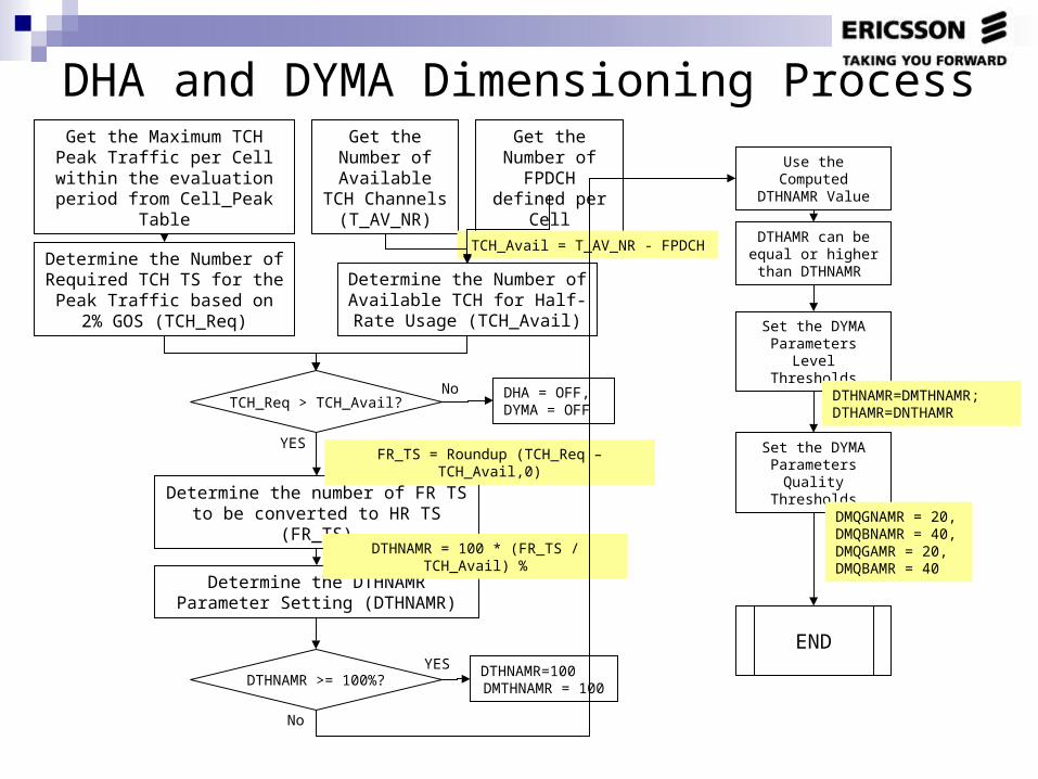
DHA and DYMA Dimensioning ProcessGet the Maximum TCH Peak
Traffic per Cell within the evaluation period from
Cell_Peak Table
Get the Number of Available
TCH Channels (T_AV_NR)
Get the Number of FPDCH
defined per Cell
Determine the Number of Required TCH TS for the Peak
Traffic based on 2% GOS (TCH_Req)
TCH_Req > TCH_Avail?
Determine the Number of Available TCH for Half-Rate
Usage (TCH_Avail)
TCH_Avail = T_AV_NR - FPDCH
DHA = OFF, DYMA = OFF
No
Determine the number of FR TS to be converted to HR TS (FR_TS)
FR_TS = Roundup (TCH_Req – TCH_Avail,0)
Determine the DTHNAMR Parameter Setting (DTHNAMR)
DTHNAMR = 100 * (FR_TS / TCH_Avail) %
DTHNAMR >= 100%?DTHNAMR=100DMTHNAMR = 100
YES
YES
Use the Computed DTHNAMR Value
No
DTHAMR can be equal or higher than
DTHNAMR
Set the DYMA Parameters Level
Thresholds
DTHNAMR=DMTHNAMR; DTHAMR=DNTHAMR
Set the DYMA Parameters Quality
Thresholds
DMQGNAMR = 20,DMQBNAMR = 40,DMQGAMR = 20,DMQBAMR = 40
END

TRA Pool Dimensioning due to DHA Reconfiguration

TRA Pool Dimensioning due to DHA Reconfiguration (1)
From the Transcoder Statistics, get the Date and
Hour of the highest number of active TRA Pool TS
(TRA_ACT_CNT_Max) within the Evaluation Period
From the Cell_Hour Table, get the TCH Traffic of all the cells within TRC on the specified
Date and Hour above.
Determine the Number of Required TCH TS for the TCH
Traffic based on 2% GOS (TCH_Req)
Get the Number of Available
TCH Channels (T_AV_NR)
Get the Number of FPDCH
defined per Cell
Determine the Number of Available TCH for Half-Rate
Usage (TCH_Avail)
TCH_Avail = T_AV_NR - FPDCH
Get the DTHNAMR
Setting
Number of Occupied FR TS before using HR
(FR_TS_THR)
FR_TS_THR = (100-DTHNAMR) * TCH_Avail
TCH_Req < FR_TS_THR?
FR_TS is equal to the TCH_Req ( HR_TS =0)
Determine the Number of FR TS used per cell
FR_TS_1 = TCH_Req
No
YES
FR_TS_2 = FR_TS_THR
Determine the Number of HR TS used per cell
HR_TS = 2 * (TCH_Req - FR_TS_THR)
A B
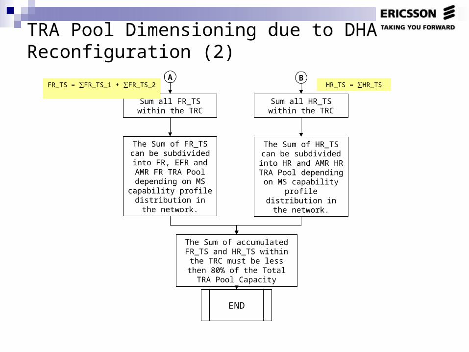
TRA Pool Dimensioning due to DHA Reconfiguration (2)
A B
Sum all FR_TS within the TRC
Sum all HR_TS within the TRC
FR_TS = ∑FR_TS_1 + ∑FR_TS_2 HR_TS = ∑HR_TS
The Sum of FR_TS can be subdivided into FR, EFR and AMR FR TRA Pool depending on MS
capability profile distribution in the
network.
The Sum of HR_TS can be subdivided into HR
and AMR HR TRA Pool depending on MS capability profile distribution in the
network.
The Sum of accumulated FR_TS and HR_TS within the TRC must be less then 80% of the Total TRA Pool Capacity
END

Paging Analysis

Background
Experiences from networks with only CS traffic show that the share of CCCH resources used for AGCH is very low and that it typically can be disregarded when dimensioning an LA. However in LA border cells or networks with a high level of GPRS traffic, the AGCH load can be so high that it affects the paging capacity. Paging performance on each cell can be expressed by the Rate of Discarded Paging.
In Ericsson System, Paging Messages sent from MSC to BSC are counted (TOTPAG), as well as discarded paging on BSC Level (TOTCONGPAG). But in the case when more than one LAC belong to one BSC, Paging Messages per LAC can be estimated based on Random Access as Answer to Paging.

Rate of Discarded Paging per Cell (1)
Statistics shall be collected on the hour with the most number of Paging Messages received by the BSC.
Formula for the Rate of Discarded Paging per Cell (One LAC per BSC)

Rate of Discarded Paging per Cell (2)
Formula for the Rate of Discarded Paging per Cell (More than one LAC per BSC)

Counter Descriptions (1)
TOTPAG - Number of paging messages received from the MSC. Object Type BSC.
TOTCONGPAG - Number of Paging messages discarded due to congestion at the BSC. Object Type BSC.
PAGCSBSC - Cumulative number of PAGING CS messages received from SGSN with paging area set to the BSC or LA. Object Type BSCGPRS.
PAGPSBSC - Cumulative number of PAGING PS messages received from SGSN with paging area set to the BSC or LA. Object Type BSCGPRS.

Counter Descriptions (2)
PAGTOOOLD - Number of discarded paging messages sent out on the PCH due to old paging messages. Object Type CELLPAG.
PAGPCHCONG - Number of discarded paging messages sent out on the PCH due to full paging queue. Object Type CELLPAG.
RAANPAG - Number of random accesses, answer to paging. Object Type RANDOMACC.
RAAPAG1 - Number of random accesses, answer to paging and the channel required is a TCH/F with dual rate mobile capability. Object Type RNDACCEXT.
RAAPAG2 Number of random accesses, answer to paging and the channel required is a TCH/F or TCH/H with dual rate mobile capability. Object Type RNDACCEXT.

Example of 3 LAC’s in one BSC
LAC 01:SUMRAAPAG = 34,400
LAC 02:
BSC A:TOTPAG+PAGCSBSC+PAGPSBSC = 130,000
LAC 03:SUMRAAPAG = 30,100
SUMRAAPAG = 25,600 SUMRAAPAG = 26,900
BSC B:TOTPAG+PAGCSBSC+PAGPSBSC = 120,000

Percentage Distribution of Random Access Answer to Paging per LAC
LA_1_dist =34,400
34,400 + 25,600= 0.5733
BSC A:
BSC B:
LA_2_distA =25,600
34,400 + 25,600= 0.4267
LA_2_distB =25,900
25,900 + 30,100= 0.4719
LA_3_dist =30,100
25,900 + 30,100= 0.5281

Estimation of Paging per LAC
Paging on LAC 01 = 130,000 * 0.5733 = 74,533
Paging on LAC 02 = Max (130,000 * 0.4267, 120,000* 0.4719) = 56,632
Paging on LAC 03 = 120,000 * 0.5281 = 63,368
