erasure correcting codes for use in near-earth and deep ... · erasure correcting codes for use in...
TRANSCRIPT
Research and Development for Space Data System Standards
ERASURE CORRECTING CODES FOR USE IN NEAR-EARTH AND DEEP-SPACE
COMMUNICATIONS
EXPERIMENTAL SPECIFICATION
CCSDS 131.5-O-1
ORANGE BOOK November 2014

Research and Development for Space Data System Standards
ERASURE CORRECTING CODES FOR USE IN NEAR-EARTH AND DEEP-SPACE
COMMUNICATIONS
EXPERIMENTAL SPECIFICATION
CCSDS 131.5-O-1
ORANGE BOOK November 2014

ERASURE CORRECTING CODES FOR USE IN NEAR-EARTH AND DEEP-SPACE COMMUNICATIONS
CCSDS 131.5-O-1 Page i November 2014
AUTHORITY
Issue: Orange Book, Issue 1
Date: November 2014
Location: Washington, DC, USA
This document has been approved for publication by the Consultative Committee for Space Data Systems (CCSDS). The procedure for review and authorization of CCSDS documents is detailed in Organization and Processes for the Consultative Committee for Space Data Systems (CCSDS A02.1-Y-4).
This document is published and maintained by:
CCSDS Secretariat National Aeronautics and Space Administration Washington, DC, USA E-mail: [email protected]
ERASURE CORRECTING CODES FOR USE IN NEAR-EARTH AND DEEP-SPACE COMMUNICATIONS
CCSDS 131.5-O-1 Page ii November 2014
FOREWORD
Through the process of normal evolution, it is expected that expansion, deletion, or modification of this document may occur. This Recommended Standard is therefore subject to CCSDS document management and change control procedures, which are defined in the Organization and Processes for the Consultative Committee for Space Data Systems (CCSDS A02.1-Y-4). Current versions of CCSDS documents are maintained at the CCSDS Web site:
http://www.ccsds.org/
Questions relating to the contents or status of this document should be sent to the CCSDS Secretariat at the e-mail address indicated on page i.
ERASURE CORRECTING CODES FOR USE IN NEAR-EARTH AND DEEP-SPACE COMMUNICATIONS
CCSDS 131.5-O-1 Page iii November 2014
At time of publication, the active Member and Observer Agencies of the CCSDS were: Member Agencies
– Agenzia Spaziale Italiana (ASI)/Italy. – Canadian Space Agency (CSA)/Canada. – Centre National d’Etudes Spatiales (CNES)/France. – China National Space Administration (CNSA)/People’s Republic of China. – Deutsches Zentrum für Luft- und Raumfahrt (DLR)/Germany. – European Space Agency (ESA)/Europe. – Federal Space Agency (FSA)/Russian Federation. – Instituto Nacional de Pesquisas Espaciais (INPE)/Brazil. – Japan Aerospace Exploration Agency (JAXA)/Japan. – National Aeronautics and Space Administration (NASA)/USA. – UK Space Agency/United Kingdom.
Observer Agencies – Austrian Space Agency (ASA)/Austria. – Belgian Federal Science Policy Office (BFSPO)/Belgium. – Central Research Institute of Machine Building (TsNIIMash)/Russian Federation. – China Satellite Launch and Tracking Control General, Beijing Institute of Tracking
and Telecommunications Technology (CLTC/BITTT)/China. – Chinese Academy of Sciences (CAS)/China. – Chinese Academy of Space Technology (CAST)/China. – Commonwealth Scientific and Industrial Research Organization (CSIRO)/Australia. – Danish National Space Center (DNSC)/Denmark. – Departamento de Ciência e Tecnologia Aeroespacial (DCTA)/Brazil. – European Organization for the Exploitation of Meteorological Satellites
(EUMETSAT)/Europe. – European Telecommunications Satellite Organization (EUTELSAT)/Europe. – Geo-Informatics and Space Technology Development Agency (GISTDA)/Thailand. – Hellenic National Space Committee (HNSC)/Greece. – Indian Space Research Organization (ISRO)/India. – Institute of Space Research (IKI)/Russian Federation. – KFKI Research Institute for Particle & Nuclear Physics (KFKI)/Hungary. – Korea Aerospace Research Institute (KARI)/Korea. – Ministry of Communications (MOC)/Israel. – National Institute of Information and Communications Technology (NICT)/Japan. – National Oceanic and Atmospheric Administration (NOAA)/USA. – National Space Agency of the Republic of Kazakhstan (NSARK)/Kazakhstan. – National Space Organization (NSPO)/Chinese Taipei. – Naval Center for Space Technology (NCST)/USA. – Scientific and Technological Research Council of Turkey (TUBITAK)/Turkey. – South African National Space Agency (SANSA)/Republic of South Africa. – Space and Upper Atmosphere Research Commission (SUPARCO)/Pakistan. – Swedish Space Corporation (SSC)/Sweden. – Swiss Space Office (SSO)/Switzerland. – United States Geological Survey (USGS)/USA.

ERASURE CORRECTING CODES FOR USE IN NEAR-EARTH AND DEEP-SPACE COMMUNICATIONS
CCSDS 131.5-O-1 Page iv November 2014
DOCUMENT CONTROL
Document Title Date Status
CCSDS 131.5-O-1
Erasure Correcting Codes for Use in Near-Earth and Deep-Space Communications, Issue 1
November 2014
Original issue

ERASURE CORRECTING CODES FOR USE IN NEAR-EARTH AND DEEP-SPACE COMMUNICATIONS
CCSDS 131.5-O-1 Page v November 2014
CONTENTS
Section Page
1 INTRODUCTION .......................................................................................................... 1-1 1.1 PURPOSE ............................................................................................................... 1-1 1.2 SCOPE .................................................................................................................... 1-1 1.3 RATIONALE .......................................................................................................... 1-1 1.4 APPLICABILITY ................................................................................................... 1-3 1.5 ORGANIZATION OF THE DOCUMENT ............................................................ 1-3 1.6 NOMENCLATURE ............................................................................................... 1-4 1.7 DEFINITIONS AND CONVENTIONS................................................................. 1-4 1.8 PATENTED TECHNOLOGIES ............................................................................ 1-9 1.9 REFERENCES ....................................................................................................... 1-9
2 OVERVIEW ................................................................................................................... 2-1
2.1 APPLICATION SCENARIOS ............................................................................... 2-1 2.2 CODING FOR ERASURE CHANNELS ............................................................... 2-4 2.3 PROTOCOL ARCHITECTURE ............................................................................ 2-9
3 ONLINE CODE DESIGN ............................................................................................. 3-1
3.1 BACKGROUND .................................................................................................... 3-1 3.2 CODE SPECIFICATION ....................................................................................... 3-1 3.3 ENCODING ............................................................................................................ 3-5 3.4 DISCUSSION—DECODING ................................................................................ 3-5
4 AD-HOC CODE DESIGN ............................................................................................ 4-1
4.1 BACKGROUND .................................................................................................... 4-1 4.2 ENCODING ............................................................................................................ 4-1
5 ERASURE CODING PROTOCOL ............................................................................. 5-1
5.1 OVERVIEW ........................................................................................................... 5-1 5.2 ARCHITECTURAL ELEMENTS ......................................................................... 5-3 5.3 EC SERVICE DEFINITION .................................................................................. 5-4 5.4 PROTOCOL SPECIFICATION ............................................................................. 5-9
ANNEX A PROTOCOL IMPLEMENTATION CONFORMANCE STATEMENT
PROFORMA (NORMATIVE) .................................................................... A-1 ANNEX B SECURITY AND PATENTS CONSIDERATIONS
(INFORMATIVE) ..........................................................................................B-1

ERASURE CORRECTING CODES FOR USE IN NEAR-EARTH AND DEEP-SPACE COMMUNICATIONS
CCSDS 131.5-O-1 Page vi November 2014
CONTENTS (continued)
Section Page
ANNEX C ANNEX TO SECTION 5, LDPC CODES PROTOTYPE IMPLEMENTATION (INFORMATIVE) ................................................. C-1
ANNEX D KIODO PROJECT MEASUREMENTS (INFORMATIVE) ................... D-1 ANNEX E PERFORMANCE ANALYSIS (INFORMATIVE) ....................................E-1 ANNEX F ABBREVIATIONS AND ACRONYMS (INFORMATIVE) ..................... F-1 ANNEX G INFORMATIVE REFERENCES (INFORMATIVE) .............................. G-1
Figure
1-1 Bit Numbering Convention ........................................................................................... 1-8 2-1 Typical Pattern Fading in Optical LEO-Downlinks ..................................................... 2-2 2-2 Encoding of Systematic IRA Codes ............................................................................. 2-6 2-3 Matrix HK after Triangulation (Left) and after Nullification (Right) ........................... 2-7 2-4 CER Versus Erasure Probability ε on the Packet Erasure Channel for
Two Codes from the Ensemble (λ3(x), ρ3(x)) ............................................................... 2-9 2-5 CCSDS Protocol Stack for Future DTN-Enabled Space Missions ............................ 2-10 2-6 CCSDS Protocol Stack with Erasure Coding Functions for Future
DTN-Enabled Space Missions .................................................................................... 2-13 5-1 Layered Approach for Implementing Erasure Codes ................................................... 5-2 5-2 Diagram of the Erasure Coding Protocol Entity ........................................................... 5-4 5-3 Erasure Coding Process Description .......................................................................... 5-11 D-1 Normalized Power for an Example Downlink ............................................................. D-1 D-2 Fade Frequency for an Example Downlink ................................................................. D-2 D-3 Fractional Fade Time Over Elevation for an Example Downlink ............................... D-2 D-4 Mean Fade Time Over Elevation for an Example Downlink ...................................... D-3 D-5 Fifty Percent Atmospheric Correlation Time Over Elevation for
an Example Downlink ................................................................................................. D-3 E-1 CERs for a Family of Rate-Compatible Flexible IRA Codes with
Block Lengths n = 512, 379, 314 and Constant k=246 ................................................. E-2 E-2 CERs for a Family of Flexible IRA Codes with Block Lengths n =
{1024, 2048, 4096, 8192} and Inner Code-Rate Ri=1/2 .............................................. E-3 E-3 CERs for Three IRA Codes with Information Length k=512 and Block
Lengths n = {576, 640, 768} Together with the Respective Singleton Bounds ........... E-4 E-4 CERs for Three IRA Codes with Information Length k=2048 and Block
Lengths n = {2304, 2560, 3072} Together with the Respective Singleton Bounds ..... E-5 E-5 CERs for Three IRA Codes with Information Length k=16384 and Block Lengths
n = {18432, 20480, 24576} Together with the Respective Singleton Bounds ............. E-6
ERASURE CORRECTING CODES FOR USE IN NEAR-EARTH AND DEEP-SPACE COMMUNICATIONS
CCSDS 131.5-O-1 Page vii November 2014
CONTENTS (continued)
Table Page
4-1 Parameters for Proposed IRA Code Family ................................................................. 4-1 4-2 Accumulator Indices for Code C1 ................................................................................. 4-3 4-3 Accumulator Indices for Code C2 ................................................................................. 4-3 4-4 Accumulator Indices for Code C3 ................................................................................. 4-4 4-5 Accumulator Indices for Code C4 ................................................................................. 4-5 4-6 Accumulator Indices for Code C5 ................................................................................. 4-6 4-7 Accumulator Indices for Code C6 ................................................................................. 4-7 4-8 Accumulator indices for code C7 .................................................................................. 4-9 4-9 Accumulator Indices for Code C8 ............................................................................... 4-11 4-10 Accumulator Indices for Code C9 ............................................................................... 4-13 5-1 EC Header Specification ............................................................................................... 5-9 5-2 Header Extensions Specification ................................................................................ 5-10 5-3 Coding Parameters Specification ................................................................................ 5-10 A-1 PICS Notation .............................................................................................................. A-2 A-2 PICS Conditional Status Notation ............................................................................... A-2 A-3 Symbols for PICS ‘Protocol Feature’ Column ............................................................ A-3 A-4 Symbols for PICS ‘Support’ Column .......................................................................... A-3

ERASURE CORRECTING CODES FOR USE IN NEAR-EARTH AND DEEP-SPACE COMMUNICATIONS
CCSDS 131.5-O-1 Page 1-1 November 2014
1 INTRODUCTION
1.1 PURPOSE
The purpose of this Experimental Specification is to define efficient erasure coding and decoding strategies for future space missions. The main target is given by high data rate telemetry applications, i.e., Earth Exploration Satellite Service (EESS) telemetry payload, and deep-space missions where stringent requirements in terms of communication reliability and delivery latency are in place. In particular, the adoption of the techniques described in this Experimental Specification can help to fulfill the requirements imposed by future missions, including those that adopt the Solar System Internetworking (SSI) architecture.
1.2 SCOPE
This Experimental Specification describes mechanisms for possible use by any class of space mission. The benefits of such application can be mostly exploited in those cases where implementation of ARQ schemes is either problematic or impossible because of specific service delay constraints.
In more detail, this book defines erasure correcting codes in the following terms:
– specification of erasure encoding techniques;
– definition of the shim-layer where the encoding (decoding) procedures will be implemented from a protocol layering perspective;
– specification of the erasure coding protocol defined to support the erasure coding procedures and allow the exchange of required signaling between the involved peers.
It does not specify:
– individual implementations or products;
– the management activities required to configure and control the service.
1.3 RATIONALE
New generations of space missions require telecommand and telemetry capabilities beyond current technologies to interconnect a spacecraft with its ground support system, or with another spacecraft. These new needs include higher data rates and better link performances, together with lower cost, mass, and power, and higher security. The wide environment range (space-Earth or space-space, near-Earth congested bands, and deep-space link operations in extreme conditions of Signal-to-Noise Ratio (SNR), links dependent on atmospheric conditions in the new high frequency bands, optical links) requires coding systems with different levels of power and bandwidth efficiency, or different levels of link reliability or delivered data quality.

ERASURE CORRECTING CODES FOR USE IN NEAR-EARTH AND DEEP-SPACE COMMUNICATIONS
CCSDS 131.5-O-1 Page 1-2 November 2014
Among the techniques that have been used in the past to guarantee reliable communications even at low signal-to-noise ratio regimes, channel coding represents a key mission-enabling technology. Nevertheless, conventional channel coding (applied at bit-level to protect transfer frames from noise) can fail to provide down/up-link reliability in many scenarios, conveniently classified as part of either optical or Radio-Frequency (RF) communications and summarized in the following:
– Optical communications.
• Fade events due to turbulence of the propagation medium and due to mispointing errors can take place. Such fade events, which can span over tens of milliseconds, can jeopardize the reception of hundreds or even thousands of transfer frames. In this context, bit-level channel coding is not sufficient.
– RF communications.
• Sync losses at the Physical Layer receiver. A similar effect can be observed for RF links, whenever the synchronization is lost at the ground-based receiver. In this case, before the correct synchronization is re-acquired, several transfer frames can be lost.
• Packet losses due to reduced link margins (e.g., due to weather-induced events). In this case, a reduction of the link margin due to atmospheric effects can lead to high transfer Frame Error Rates (FERs) lasting for relatively long time intervals, such that specific mission reliability requirements cannot be met. The correlation in the signal-to-noise values in time can represent an issue that a conventional bit-level code cannot overcome.
• Finally, in the case of file-based transmissions, even moderate-to-low FER (e.g., on the order of 10-3) could compromise the correct reception of the complete file.
The aforementioned scenarios, especially when Automatic Repeat Queuing (ARQ) strategies are not feasible (because of large propagation delays or lack of a forward or return link), require the adoption of novel countermeasures gathered from the field of the so-called erasure correcting codes.
Erasure correcting codes apply the same philosophy of bit-level channel coding, by working on information packets (e.g., transfer frames, CFDP PDUs, etc.) rather than bits or symbols. In more words, redundancy packets are generated out of a design-specific number of information packets. Information packets are treated as any PDUs generated by protocols running above the CCSDS Encapsulation Service and not including the Space Packet Protocol (SPP). The redundancy packets, which are transmitted together with the information ones, can be exploited at the receiver side to recover packet losses. Hence they provide an additional level of protection to that already available at the Physical Layer in terms of the conventional bit-level channel coding. More precisely, bit-level codes can correct errors caused by noise or fast fading effects, whereas erasure correcting codes can be implemented at the higher layer of the protocol stack to recover the data packets lost because of slow fading events. This way they should provide sufficient time diversity to cope with moderate-
ERASURE CORRECTING CODES FOR USE IN NEAR-EARTH AND DEEP-SPACE COMMUNICATIONS
CCSDS 131.5-O-1 Page 1-3 November 2014
length signal outages. In this sense, they represent a natural complement to channel coding techniques for application over optical and RF downlink communications.
1.4 APPLICABILITY
This Experimental Specification applies to cross-support situations for near-Earth Exploration Satellite Services and deep-space payload and telemetry. It includes comprehensive specification of the data formats and procedures for inter-Agency cross support. It is neither a specification of, nor a design for, real systems that may be implemented for existing or future missions.
This Experimental Specification is applicable to those missions for which cross support based on capabilities described in this document is anticipated. Where mandatory capabilities are clearly indicated in sections of this Experimental Recommendation, it is mandatory to implement them when this document is used as a basis for cross support. Where options are allowed or implied, implementation of these options is subject to specific agreements between the parties involved.
1.5 ORGANIZATION OF THE DOCUMENT
This document is structured as follows:
– Section 2 contains a description of the application scenarios and an overview of the erasure coding schemes developed next in terms of encoding, decoding, and protocol implementation issues.
– Section 3 contains the specification of online LDPC codes for erasure recovery along with the description of the encoding algorithms recommended for application in the considered scenarios.
– Section 4 contains the specification of ad-hoc LDPC-based erasure codes in case no flexibility requirements are to be met, in contrast to the design given in section 3.
– Section 5 contains the specification of the erasure coding protocol and the related CCSDS protocol extensions where necessary.
– Annex A contains the Protocol Implementation Conformance Statement (PICS) Proforma.
– Annex B contains the observations about security issues and licenses for patent use.
– Annex C contains a note about the LDPC codes prototype implementation.
– Annex D contains the details related to the Kirari Optical Satellite Downlinks to Oberpfaffenhofen (KIODO) measurement campaigns used to introduce optical link propagation issues.
ERASURE CORRECTING CODES FOR USE IN NEAR-EARTH AND DEEP-SPACE COMMUNICATIONS
CCSDS 131.5-O-1 Page 1-4 November 2014
– Annex E contains the performance figures related to codes designed and presented in sections 3 and 4, respectively.
– Annex F contains the list of acronyms.
– Annex G contains the informative references.
1.6 NOMENCLATURE
1.6.1 NORMATIVE TEXT
The following conventions apply for the normative specifications in this Recommended Standard:
a) the words ‘shall’ and ‘must’ imply a binding and verifiable specification;
b) the word ‘should’ implies an optional, but desirable, specification;
c) the word ‘may’ implies an optional specification;
d) the words ‘is’, ‘are’, and ‘will’ imply statements of fact.
NOTE – These conventions do not imply constraints on diction in text that is clearly informative in nature.
1.6.2 INFORMATIVE TEXT
In the normative sections of this document, informative text is set off from the normative specifications either in notes or under one of the following subsection headings:
– Overview;
– Background;
– Rationale;
– Discussion.
1.7 DEFINITIONS AND CONVENTIONS
1.7.1 DEFINITIONS
1.7.1.1 Definitions from OSI Basic Reference Model
This Experimental Specification makes use of a number of terms defined in reference [1]. The use of those terms in this Experimental Specification is to be understood in a generic sense, i.e., in the sense that those terms are generally applicable to any of a variety of

ERASURE CORRECTING CODES FOR USE IN NEAR-EARTH AND DEEP-SPACE COMMUNICATIONS
CCSDS 131.5-O-1 Page 1-5 November 2014
technologies that provide for the exchange of information between real systems. Those terms are:
a) entity;
b) service;
c) service-access-point, SAP;
d) service-data-unit, SDU;
e) protocol-data-unit, PDU;
f) service user;
g) service provider.
1.7.1.2 Definitions from OSI Service Definition Conventions
This Experimental Specification makes use of a number of terms defined in reference [2]. The use of those terms in this Experimental Specification is to be understood in a generic sense, i.e., in the sense that those terms are generally applicable to any of a variety of technologies that provide for the exchange of information between real systems. Those terms are:
– indication;
– primitive;
– request;
– response.
1.7.1.3 Definitions from RFC 5050 (BP)
This Experimental Specification makes use of a number of terms defined in reference [G1].
– bundle: A PDU of the DTN Bundle Protocol.
– bundle node (also simply ‘node’): Any entity that can send and/or receive bundles.
– bundle protocol agent, BPA: Node component that offers the BP services and executes the procedures of the Bundle Protocol.
– convergence layer adapter, CLA: Adapter that sends and receives bundles on behalf of the BPA.

ERASURE CORRECTING CODES FOR USE IN NEAR-EARTH AND DEEP-SPACE COMMUNICATIONS
CCSDS 131.5-O-1 Page 1-6 November 2014
1.7.1.4 Definitions from RFC 5326 (LTP)
This Experimental Specification makes use of a number of terms defined in reference [G2]. Some of the definitions needed for section 5 of this document are reproduced here for convenience and the sake of clarity.
– block: An array of contiguous octets of application data handed down by the upper layer protocol (typically Bundle Protocol) to be transmitted from one LTP client service instance to another.
Any subset of a block comprising contiguous octets beginning at the start of the block is termed a ‘block prefix’, and any such subset of the block ending with the end of the block is termed a ‘block suffix’.
– red-part: The block prefix that is to be transmitted reliably, i.e., subject to acknowledgment and retransmission.
– green-part: The block suffix that is to be transmitted unreliably, i.e., not subject to acknowledgments or retransmissions. If present, the green-part of a block begins at the octet following the end of the red-part.
– sender: The data sending peer of a session.
– receiver: The data receiving peer of a session.
– segment: The unit of LTP data transmission activity. It is the data structure transmitted from one LTP engine to another in the course of a session. Each LTP segment is of one of the following types: Data Segment (DS), Report Segment (RS), Report-Acknowledgment (RA) segment, cancel segment, cancel-acknowledgment segment.
1.7.1.5 Definition from CCSDS 130.2-G-2
This Experimental Specification makes use of the following term adapted from reference [G3]:
– transfer frame: Protocol Data Unit of the Space Data Link Protocols.
1.7.1.6 Terms Defined in This Experimental Specification
– application data unit, ADU: A length-delimited information bit-vector input and output of the erasure coding and decoding protocol entities, respectively.
– data packet (also simply ‘packet’): An arbitrary integer number of octets.
– information packet: Any (data) packet generated by CCSDS protocols and possible input of erasure coding.
– redundancy packet: Any (data) packet generated by erasure coding.

ERASURE CORRECTING CODES FOR USE IN NEAR-EARTH AND DEEP-SPACE COMMUNICATIONS
CCSDS 131.5-O-1 Page 1-7 November 2014
– encoding matrix: The matrix where each input ADU is copied for erasure encoding functions. A matrix dimension depends on the specific erasure correcting code being used.
– LEC word, LW: Each single row of the encoding matrix.
– LEC symbol, LS: A length-delimited information bit-vector output and input of the encoding and decoding engines, respectively.
– data redundancy unit, DRU: A length-delimited information bit-vector generated by the encoding engine, which applies an encoding process to the LWs defined by the encoding matrix.
– erasure coding data unit, ECDU: A length-delimited information bit-vector composed of Erasure Coding (EC) Payload and EC Header.
– erasure coding header, EC header: Header appended to LSes, carrying information about the characteristics of the encoding process, needed at the receiver side to correctly process the incoming ECDUs and start the decoding process.
– erasure coding payload, EC Payload: One LS data unit.
– erasure coding protocol entity: The protocol entity implemented on the sender peer responsible for performing erasure coding on the incoming ADUs, generating the corresponding LSes, and eventually generating the ECDUs. It is composed of the encoding matrix, the encoding engine, and the protocol engine.
– encoding engine: The functional block responsible for performing the encoding functions on the encoding matrix, based on the specific design of the erasure correcting code being adopted.
– encoding process: The set of encoding functions carried out by the encoding engine.
– erasure decoding protocol entity: The protocol entity implemented on the receiver peer responsible for performing erasure decoding on the incoming ECDUs and reconstructing the corresponding ADUs in case the decoding process performed by the decoding engine is successful.
– decoding engine: The functional block responsible for performing the decoding functions on the relevant LSes transported in ECDUs.
– decoding process: The set of decoding functions carried out by the decoding engine.
– protocol engine: The functional block responsible for fetching the LSes coming from erasure engine and perform the packetization service.
– coding parameters, CP: The set of parameters used to by the encoding engine to configure and run the encoding process.
– forward link: That portion of a space link in which the caller transmits and the responder receives (typically a telecommand link).

ERASURE CORRECTING CODES FOR USE IN NEAR-EARTH AND DEEP-SPACE COMMUNICATIONS
CCSDS 131.5-O-1 Page 1-8 November 2014
– return link: That portion of a space link in which the responder transmits and the caller receives (typically a telemetry link).
– erasure coding shim layer, EC shim layer: The protocol layer responsible for erasure encoding and decoding operations, implemented as part of the erasure coding protocol.
– erasure coding protocol, EC protocol: The set of functions and formats (semantic and syntactic) used to define:
• the erasure coding and decoding operations of the Erasure Coding and Decoding Protocol Entities.
• the description of the state machines within the Erasure Coding and Decoding Protocol Entities.
• the PDUs that are exchanged between these entities.
– packetization service: Service performed by the protocol engine in order to format LSes by appending a header and a trailer, thus generating ECDUs.
1.7.2 CONVENTIONS
In this document, the following convention is used to identify each bit in an N-bit field. The first bit in the field to be transmitted (i.e., the most left justified when drawing a figure) is defined to be ‘Bit 0’, the following bit is defined to be ‘Bit 1’, and so on up to ‘Bit N-1’. When the field is used to express a binary value (such as a counter), the Most Significant Bit (MSB) is the first transmitted bit of the field, i.e., ‘Bit 0’ (see figure 1-1).
BIT 0 BIT N–1
N-BIT DATA FIELD
FIRST BIT TRANSFERRED = MSB
Figure 1-1: Bit Numbering Convention
In accordance with standard data-communications practice, data fields are often grouped into 8-bit ‘words’ which conform to the above convention. Throughout this Specification, such an 8-bit word is called an ‘octet’.
The numbering for octets within a data structure starts with ‘0’.
The convention for matrices differs from that for bit fields. Matrices are indexed beginning with the number ‘1’.

ERASURE CORRECTING CODES FOR USE IN NEAR-EARTH AND DEEP-SPACE COMMUNICATIONS
CCSDS 131.5-O-1 Page 1-9 November 2014
1.8 PATENTED TECHNOLOGIES
The CCSDS draws attention to the fact that it is claimed that compliance with this document may involve the use of patents. The CCSDS takes no position concerning the evidence, validity, and scope of these patent rights. The holders of these patent rights have assured the CCSDS that they are willing to negotiate licenses under reasonable and non-discriminatory terms and conditions with applicants throughout the world. In this respect, the statements of the holders of these patent rights are registered with CCSDS. Information can be obtained from the CCSDS Secretariat at the address indicated on page i. Contact information for the holders of these patent rights is provided in annex B.
Attention is drawn to the possibility that some of the elements of this document may be the subject of patent rights other than those identified above. The CCSDS shall not be held responsible for identifying any or all such patent rights.
1.9 REFERENCES
The following documents contain provisions which, through reference in this text, constitute provisions of this Experimental Specification. At the time of publication, the editions indicated were valid. All documents are subject to revision, and users of this Experimental Specification are encouraged to investigate the possibility of applying the most recent editions of the documents indicated below. The CCSDS Secretariat maintains a register of currently valid CCSDS documents.
[1] Information Technology—Open Systems Interconnection—Basic Reference Model: The Basic Model. 2nd ed. International Standard, ISO/IEC 7498-1:1994. Geneva: ISO, 1994.
[2] Information Technology—Open Systems Interconnection—Basic Reference Model—Conventions for the Definition of OSI Services. International Standard, ISO/IEC 10731:1994. Geneva: ISO, 1994.
[3] Encapsulation Service. Issue 2. Recommendation for Space Data System Standards (Blue Book), CCSDS 133.1-B-2. Washington, D.C.: CCSDS, October 2009.
[4] “Protocol Identifier for Encapsulation Service.” Space Assigned Numbers Authority. http://sanaregistry.org/r/protocol_id/.
[5] W. Eddy and E. Davies. Using Self-Delimiting Numeric Values in Protocols. RFC 6256. Reston, Virginia: ISOC, May 2011.
[6] Proximity-1 Space Link Protocol—Coding and Synchronization Sublayer. Issue 2. Recommendation for Space Data System Standards (Blue Book), CCSDS 211.2-B-2. Washington, D.C.: CCSDS, December 2013.
ERASURE CORRECTING CODES FOR USE IN NEAR-EARTH AND DEEP-SPACE COMMUNICATIONS
CCSDS 131.5-O-1 Page 1-10 November 2014
[7] Digital Video Broadcasting (DVB); Second generation framing structure, channel coding and modulation systems for Broadcasting, Interactive Services, News Gathering and other broadband satellite applications (DVB-S2). ETSI EN 302 307 V1.3.1 (2013-03). Sophia-Antipolis: ETSI, 2013.
NOTE – Annex G contains Informative References.

ERASURE CORRECTING CODES FOR USE IN NEAR-EARTH AND DEEP-SPACE COMMUNICATIONS
CCSDS 131.5-O-1 Page 2-1 November 2014
2 OVERVIEW
2.1 APPLICATION SCENARIOS
2.1.1 GENERAL
According to the studies performed in the framework of space communications, two main scenarios are identified and are detailed next:
– optical near-Earth and deep-space communications;
– RF near-Earth and deep-space communications.
2.1.2 OPTICAL NEAR-EARTH AND DEEP-SPACE COMMUNICATIONS
2.1.2.1 Signal Fading in Downlink
Optical communications carried out over deep-space and near-Earth links can be affected by signal degradations because of channel fading introduced by several sources:
– atmospheric perturbations due to optical turbulence (random refractive-index variations) in cases of links established at large zenith angles can cause symbol synchronization and data losses;
– cloud coverage can cause signal blockage, requiring the implementation of a ground station network.
The use of larger telescope apertures leads to weaker and slower scintillation events. The corresponding fading events’ duration is on the order of 1-10 ms. Adaptive optics can be used to reduce the receiver’s field of view; however, telescopes have to be dimensioned with proper resolution and bandwidth to avoid additional fading. On the other hand, bandwidth of the tracking control loop is on the order of KHz, thus potentially leading to fading events of duration comparable to that caused by turbulence.
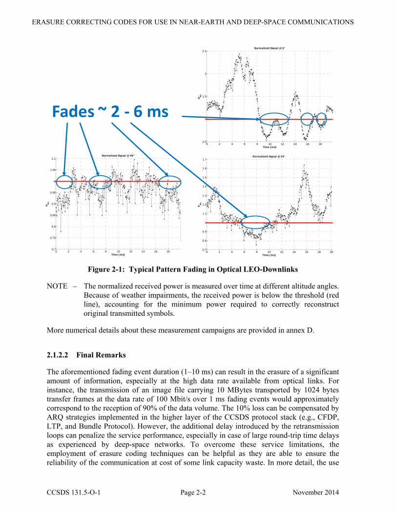
Numerical evidence of the aforementioned phenomena was obtained during measurement campaigns carried out in the framework of the KIODO project, where DLR, JAXA, and NICT were involved. The measurements revealed fluctuations of the received power, giving rise to fading events causing the degradation of the optical link performance. In particular, fading durations ranging between 2 and 6 ms were recorded. Figure 2-1 illustrates an example of such measurements.
ERASURE CORRECTING CODES FOR USE IN NEAR-EARTH AND DEEP-SPACE COMMUNICATIONS
CCSDS 131.5-O-1 Page 2-2 November 2014
Fades ~ 2 ‐ 6 ms
0 2 4 6 8 10 12 14 16 180.5
1
1.5
2
2.5Normalized Signal @ 5°
Time (ms)
PR
x
0 2 4 6 8 10 12 14 16 18 200.7
0.8
0.9
1
1.1
1.2
1.3
1.4
1.5
1.6
1.7Normalized Signal @ 25°
Time (ms)
PR
x
0 2 4 6 8 10 12 14 16 180.7
0.75
0.8
0.85
0.9
0.95
1
1.05
1.1Normalized Signal @ 46°
Time (ms)
PR
x
Figure 2-1: Typical Pattern Fading in Optical LEO-Downlinks
NOTE – The normalized received power is measured over time at different altitude angles. Because of weather impairments, the received power is below the threshold (red line), accounting for the minimum power required to correctly reconstruct original transmitted symbols.
More numerical details about these measurement campaigns are provided in annex D.
2.1.2.2 Final Remarks
The aforementioned fading event duration (1–10 ms) can result in the erasure of a significant amount of information, especially at the high data rate available from optical links. For instance, the transmission of an image file carrying 10 MBytes transported by 1024 bytes transfer frames at the data rate of 100 Mbit/s over 1 ms fading events would approximately correspond to the reception of 90% of the data volume. The 10% loss can be compensated by ARQ strategies implemented in the higher layer of the CCSDS protocol stack (e.g., CFDP, LTP, and Bundle Protocol). However, the additional delay introduced by the retransmission loops can penalize the service performance, especially in case of large round-trip time delays as experienced by deep-space networks. To overcome these service limitations, the employment of erasure coding techniques can be helpful as they are able to ensure the reliability of the communication at cost of some link capacity waste. In more detail, the use
ERASURE CORRECTING CODES FOR USE IN NEAR-EARTH AND DEEP-SPACE COMMUNICATIONS
CCSDS 131.5-O-1 Page 2-3 November 2014
of erasure coding techniques implemented with code-rate ranging from 0.9 to 0.99 is able to achieve data communication reliability with negligible capacity underutilization (1-10%) and affordable on-board storage requirements for the encoding functions.
2.1.3 RF NEAR-EARTH AND DEEP-SPACE COMMUNICATIONS
2.1.3.1 Downlink Signal Degradation
RF deep-space communications can be hampered by a number a factors, which eventually lead to the degradation of the overall performance in spite of link budget margin and channel coding techniques implemented at the Data Link and Physical Layers. In particular, it is worth considering:
– Adverse weather conditions. Effects of weather on the received signal can last from a fraction of an hour to several hours. This causes the received data to be unreliable over such duration and effectively generates very long erasures in the received data, as observed in the Ka-band measurements done at Goldstone, Madrid, and Canberra DSN complexes.
– Pointing errors. Because of antenna pointing errors, the receiver needs to reacquire the signal. During such time the data is lost or unreliable, resulting in one or a few transfer frame erasures.
– Out-of-sync receiver (loss of sync or delay in acquisition). Erasures in digital transmission of data can be due to initial acquisition of sync and occasional loss of sync. In these circumstances, data is lost while the receiver is resynchronizing. This is particularly noticeable in the case of Sun interference, depending on the relative position between Sun and spacecraft. The events, though predictable, can give rise to erasures of up to 50 transfer frames.
Actually, adverse weather conditions, though definitely penalizing Ka-band space missions, can be hardly compensated by use of erasure codes, since the long duration of such events (hours) would require the implementation of very large storage units, which is an option not currently feasible on spacecraft.
The case of the out-of-sync receiver is instead particularly promising for the application of erasure codes in order to compensate the loss of tens of transfer frames. Further, the capability of predict such events also allows use of erasure codes during these events and therefore limits the link bandwidth waste (due to erasure coding overhead) as much as possible.
2.1.3.2 Final Remarks
Among all the aforementioned erasure sources, the case of out-of-sync event turns out to be the hardest to counteract because of the significant number of erased transfer frames (as high as 50 in some measurements) that may occur. In this respect, the implementation of erasure

ERASURE CORRECTING CODES FOR USE IN NEAR-EARTH AND DEEP-SPACE COMMUNICATIONS
CCSDS 131.5-O-1 Page 2-4 November 2014
codes can mitigate the detrimental effects of synchronization losses with a very limited bandwidth waste (code-rate assumed between 0.9 and 0.99). Alternatively it is also possible to think about combining erasure codes with enhanced Physical Layer design in order to distribute the complexity between different layers of the protocol stack.
2.2 CODING FOR ERASURE CHANNELS
2.2.1 INTRODUCTION
Erasure codes are typically employed in the upper layers of communication systems to counteract packet losses. Hence, it is assumed that lower layers implement an entity detecting transfer frames as either correct or wrong (in this case transfer frame are actually erased), depending on whether the codewords composing each transfer frame are decoded correctly or not. Erasure codes are particularly appealing in scenarios where the data integrity plays a crucial role (as complement to lower layer coding schemes), in scenarios where long delays make ARQ schemes impractical, or when complexity limitations prevent the use of long Physical Layer codes.
Low-Density Parity-Check (LDPC) codes (reference [G7]) for recovering packet erasures were for instance considered in reference [G13]. Through the use of a (nearly) ideal decoding algorithm and an optimized code design, performances close to theoretical limits may be achieved, while decoding complexity is kept low. This is mainly due to the sparse nature of the proposed codes. The solution of reference [G13] has been already tested in the framework of Digital Video Broadcasting—Satellite Services to Handhelds (DVB-SH) standardization activities. The tests were performed by broadcasting an encoded video stream in S-band through the ETS-VIII geostationary satellite. At the receiver, after Physical Layer decoding and error detection, the packet stream was decoded in real-time on an 800 MHz ultra-portable PC performing decoding in software. On a commercial personal computer data rates around 1.5 Gb/s were demonstrated.
2.2.2 ESSENTIALS
In the following, a binary linear block code is designated by ( , )C n k where n is the codeword (or block) length and k the information length (or code dimension). The resulting code rate is given by /R k n= . LDPC codes, i.e., a class of linear block codes having sparse parity-check matrices, are considered here. The ( )m n× parity-check matrix H fully defines the LDPC code, where in the following only the case where m n k= − is taken into account.
An LDPC code may also be represented via a bipartite Tanner graph, i.e., a graph with two types of nodes, Variable Nodes (VNs) and Check Nodes (CNs), such that each edge connects two different types of nodes. While the VNs correspond to the code symbols (associated with the columns of H) the CNs correspond to the constraints on the code symbols (i.e., the rows of H). Whenever a VN Vi is connected to a CN Cj the corresponding entry hj,i of the parity-check matrix H is different from zero.
ERASURE CORRECTING CODES FOR USE IN NEAR-EARTH AND DEEP-SPACE COMMUNICATIONS
CCSDS 131.5-O-1 Page 2-5 November 2014
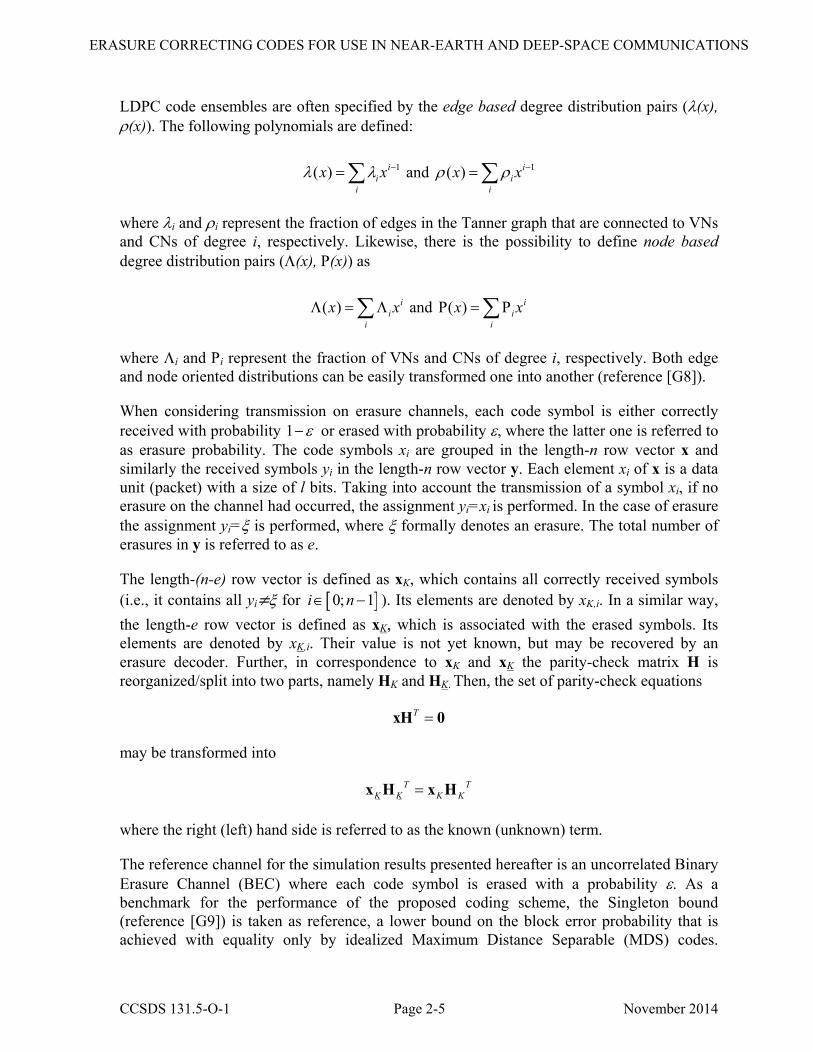
LDPC code ensembles are often specified by the edge based degree distribution pairs (λ(x), ρ(x)). The following polynomials are defined:
1( ) ii
ix xλ λ −=∑ and 1( ) i
ii
x xρ ρ −=∑
where λi and ρi represent the fraction of edges in the Tanner graph that are connected to VNs and CNs of degree i, respectively. Likewise, there is the possibility to define node based degree distribution pairs (Λ(x), Ρ(x)) as
( ) ii
ix xΛ = Λ∑ and ( ) i
ii
x xΡ = Ρ∑
where Λi and Ρi represent the fraction of VNs and CNs of degree i, respectively. Both edge and node oriented distributions can be easily transformed one into another (reference [G8]).
When considering transmission on erasure channels, each code symbol is either correctly received with probability 1 ε− or erased with probability ε, where the latter one is referred to as erasure probability. The code symbols xi are grouped in the length-n row vector x and similarly the received symbols yi in the length-n row vector y. Each element xi of x is a data unit (packet) with a size of l bits. Taking into account the transmission of a symbol xi, if no erasure on the channel had occurred, the assignment yi=xi is performed. In the case of erasure the assignment yi=ξ is performed, where ξ formally denotes an erasure. The total number of erasures in y is referred to as e.
The length-(n-e) row vector is defined as xK, which contains all correctly received symbols (i.e., it contains all yi ξ for [ ]0; 1i n∈ − ). Its elements are denoted by xK,i. In a similar way, the length-e row vector is defined as xK, which is associated with the erased symbols. Its elements are denoted by xK,i. Their value is not yet known, but may be recovered by an erasure decoder. Further, in correspondence to xK and xK the parity-check matrix H is reorganized/split into two parts, namely HK and HK. Then, the set of parity-check equations
T =xH 0
may be transformed into
T TK K K K=x H x H
where the right (left) hand side is referred to as the known (unknown) term.
The reference channel for the simulation results presented hereafter is an uncorrelated Binary Erasure Channel (BEC) where each code symbol is erased with a probability ε. As a benchmark for the performance of the proposed coding scheme, the Singleton bound (reference [G9]) is taken as reference, a lower bound on the block error probability that is achieved with equality only by idealized Maximum Distance Separable (MDS) codes.

ERASURE CORRECTING CODES FOR USE IN NEAR-EARTH AND DEEP-SPACE COMMUNICATIONS
CCSDS 131.5-O-1 Page 2-6 November 2014
Idealized means that MDS codes may not exist for certain code parameters and finite field orders. Additionally, it is necessary to resort to the Berlekamp bound (reference [G10]), being an upper bound on the block error probability of the (n,k) random code ensemble.
2.2.3 ENCODING
Encoding consists of generating n code symbols out of the k information symbols at the encoder output. Only systematic codes are considered, i.e., codes for which the information symbols are also transmitted and are thus part of the codeword. Hence the length-n codeword can be formally split into a part that corresponds to the k information symbols and a part that is made up by the m parity symbols. By noting that each of the m parity symbols can be expressed as a linear combination of the k information symbols, encoding may be generally described follows:
a) The m parity symbols are considered as erasures, i.e., a received vector y that contains all the k information symbols and m erasures corresponding to the parity symbols is assumed.
b) The Maximum-Likelihood Pivoting (ML-P) decoder is used to recover the erasures by solving T T
K K K K=x H x H .
Above, encoding of LDPC codes is turned into a pure decoding problem, where the decoder works only with the parity-check matrix H of the code. A detailed discussion on the ML-P decoder follows in the next subsection.
For some classes of LDPC codes, such as Irregular-Repeat-Accumulate (IRA) LDPC codes, encoding can be further simplified (reference [G11]). The parity-parity check matrix H may be formally expressed as [ | ]u p=H H H , where for the IRA codes under consideration uH is a sparse (unstructured) matrix corresponding to the information symbols and pH is a double diagonal matrix corresponding to the parity symbols. As a result of the double diagonal structure of pH , each parity symbol is a sum of a set of information symbols and another, already known parity symbol (reference [G11]). This is visualized in figure 2-2, where the upper branch stands for the information symbols and the lower branch for the parity symbols. The double diagonal matrix pH corresponds to an accumulator with transfer function 1/ (1 )D+ . Encoding is performed with linear complexity in the block length. The code construction in the code design (3.2) also embeds this (double) diagonal structure.
H Tu
11+D
Figure 2-2: Encoding of Systematic IRA Codes

ERASURE CORRECTING CODES FOR USE IN NEAR-EARTH AND DEEP-SPACE COMMUNICATIONS
CCSDS 131.5-O-1 Page 2-7 November 2014
2.2.4 DECODING
The ML-P decoding of LDPC codes (reference [G13]) is considered. ML-P decoding is a reduced complexity decoding algorithm that attempts to solve most of the erasures by applying light ITerative (IT) decoding, whereas only a small number of erasures α (referred to as pivots) is resolved by more complex Maximum-Likelihood (ML) decoding if necessary. On erasure channels, ML decoding may be well implemented by Gauss-Jordan elimination. The performance of the algorithm ranges from that of IT decoding to that of ML decoding, depending on the computational capabilities of the decoding platform. More specifically, the algorithm performance can be adjusted by properly setting the parameter αmax, i.e., the maximum number of pivots and hence the dimension of the system on which Gauss-Jordan elimination shall be applied. If αmax=0 only IT decoding is performed, while for αmax=m decoding is done.
T R
RC
−
−−
(−
)
T R
RC
−
−−
(−
)
Figure 2-3: Matrix HK after Triangulation (Left) and after Nullification (Right)
In more detail, the ML-P decoding algorithm attempts to recover the values for xK by solving T T
K K K K=x H x H . The algorithm can be summarized as follows:
a) Approximate lower triangulation procedure. The matrix HK is transformed into an approximate triangular matrix, as depicted in figure 2-3 (left), by row and column permutations only. Accordingly permutations of xK and T
K Kx H are also required. The obtained matrix is composed of a lower triangular matrix T and of the three sparse matrices C, RU, and RL. In the process, some of the columns blocking the triangulation of HK are moved to the right-most part of HK and hence form RU, and RL at the end of the procedure. The α unknowns associated with such columns are called reference variables or pivots. The choice of the pivots can be made in different

ERASURE CORRECTING CODES FOR USE IN NEAR-EARTH AND DEEP-SPACE COMMUNICATIONS
CCSDS 131.5-O-1 Page 2-8 November 2014
ways. In the sequel, the Maximum Column Weight (MCW) pivoting algorithm from reference [G13] is used.
b) Nullification procedure. T is transformed into an identity matrix by row additions. Moreover, C is made equal to the zero matrix by row additions, leading to the matrix depicted in figure 2-3 (right). It should be noted that, because of the row additions, both RU, and RL may not be sparse any more. Corresponding row additions on the known term are also required.
c) Gaussian elimination procedure. Gauss-Jordan elimination is applied to RL to recover the α reference variables. Corresponding manipulations on the known term are also required.
d) Final IT decoding step. The remaining e α− unknowns are solved by simple IT decoding.
2.2.5 PERFORMANCE
To illustrate the capabilities of LDPC codes under ML-P decoding on erasure channels, two codes from the ensemble (λ3(x), ρ3(x)) given as follows are taken as reference:
2 17 343
143
( ) 0.064286 x + 0.402172 x + 0.047459 x3 + 0.051081 x7+0.115661 x + 0.319342x
( ) x .
x
x
λ
ρ
=
=
Both example codes have rate R=2/3, and parameters of (1536,1024) and (12288,8192), respectively. The Codeword Error Rate (CER) versus the channel erasure probability for both codes is depicted in figure 2-4. As a reference the Singleton bound is depicted. The results show a negligibly small gap of the two codes with respect to the theoretical bound. It should be noted that, despite the excellent code performance, high decoding speeds are achieved (cf. reference [G13] where throughputs on the order of Gb/s were measured).

ERASURE CORRECTING CODES FOR USE IN NEAR-EARTH AND DEEP-SPACE COMMUNICATIONS
CCSDS 131.5-O-1 Page 2-9 November 2014
Figure 2-4: CER Versus Erasure Probability ε on the Packet Erasure Channel for Two Codes from the Ensemble (λ3(x), ρ3(x))
2.3 PROTOCOL ARCHITECTURE
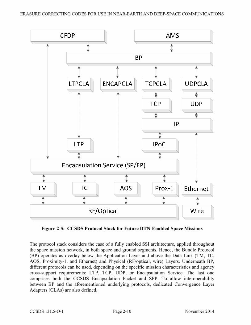
The advantages offered by erasure codes, pointed out in the previous subsection, support the idea of implementing an erasure coding strategy within the CCSDS protocol stack (reference [G5]). The CCSDS protocol architecture envisioned for future deep-space links follows the layering concept of the ISO/OSI protocol stack: Physical, Data Link, Network, Transport, and Application Layer. The description provided in reference [G14] provides some more details about the space communication protocols belonging to each layer and the architecture solutions for space missions. Further, reference [G15] shows the possible extensions of the CCSDS architecture in terms of the DTN protocol architecture for its potential in future space missions. Merging the architectural considerations drawn in references [G14] and [G15], it is possible to have a more precise and comprehensive view of the CCSDS protocol for future space missions, as depicted in figure 2-5.
ERASURE CORRECTING CODES FOR USE IN NEAR-EARTH AND DEEP-SPACE COMMUNICATIONS
CCSDS 131.5-O-1 Page 2-10 November 2014
Figure 2-5: CCSDS Protocol Stack for Future DTN-Enabled Space Missions
The protocol stack considers the case of a fully enabled SSI architecture, applied throughout the space mission network, in both space and ground segments. Hence, the Bundle Protocol (BP) operates as overlay below the Application Layer and above the Data Link (TM, TC, AOS, Proximity-1, and Ethernet) and Physical (RF/optical, wire) Layers. Underneath BP, different protocols can be used, depending on the specific mission characteristics and agency cross-support requirements: LTP, TCP, UDP, or Encapsulation Service. The last one comprises both the CCSDS Encapsulation Packet and SPP. To allow interoperability between BP and the aforementioned underlying protocols, dedicated Convergence Layer Adapters (CLAs) are also defined.
ERASURE CORRECTING CODES FOR USE IN NEAR-EARTH AND DEEP-SPACE COMMUNICATIONS
CCSDS 131.5-O-1 Page 2-11 November 2014
From this architectural retrospective, it is possible to see that erasure coding can be in principle applied at any layer of the sketched CCSDS protocol architecture, where the concept of ‘packet’ can be defined.
– Application Layer: Erasure coding can be applied either online or offline. In the former case, coding strategies can be tailored to specific content being generated by the application. In the latter, pre-coding of content is carried out offline; the application is exclusively in charge of forwarding the encoded content to the underlying protocol stack.
– Transport Layer: Erasure Coding is applied on end-to-end basis: the coding strategy can be configured according to the content carried by data packets and to the error protection they may need. This approach allows keeping the underlying protocol stack unmodified, offering several advantages in terms of flexibility and modularity of the whole deep-space communication system design. This approach has, however, the limitation of applying the coding strategy according to the characteristics of the link most prone to link errors.
– Network Layer (reference [G6]): Erasure coding works on a point-to-point basis, thus allowing efficient contrasting of packet erasures experienced with different loss patterns in a multi-hop environment. The main drawback is represented by the necessity to modify the different Network Layer protocol specifications that may be present on the network segments, depending on the space missions. This can betoo burdensome from an implementation point of view.
– Data Link Layer: Similarly to the case when erasure coding is applied to the Network Layer, the strategy is applied on a point-to-point basis, so as to match the characteristics of each transmission link. Also in this case, the application of erasure codes may result in the modification of a large number of devices, thus introducing additional costs during the mission planning phase.
It is recommended that erasure codes be implemented as close as possible to the Physical Layer in order to minimize the propagation of transfer frame erasures, which can lead to larger information losses perceived at the higher layers in case of information packet aggregation. On the other hand, end-to-end solutions are more convenient over point-to-point solutions because of complexity costs’ reductions, but are certainly less efficient as they imply a non-negligible capacity waste.
In general, it possible to consider four possible coding strategies (reference [G4]):
a) Pure FEC;
b) Type-I Hybrid ARQ;
c) Type-II Hybrid ARQ;
d) Weather Genie.

ERASURE CORRECTING CODES FOR USE IN NEAR-EARTH AND DEEP-SPACE COMMUNICATIONS
CCSDS 131.5-O-1 Page 2-12 November 2014
The first one consists in the generation and transmission of information and redundancy units over the forward link. Solutions b) and c) combine advantages of FEC and ARQ strategies: Type-I Hybrid ARQ allows retransmitting the information symbols that could not be recovered at the destination through erasure decoding; Type-II Hybrid ARQ consists in sending additional redundancy symbols upon notification of failed erasure decoding at the receiver side. Weather Genie approach exploits the availability of a forward link (established between the ground station and the spacecraft) to acquire information about the channel state and to adapt the coding strategy accordingly.
Weather Genie is the least appropriate as its implementation introduces additional complexity on the encoder side and requires the interaction with the receiver to acquire information about the channel status. On the other hand, Pure FEC is the simplest strategy to be implemented as it does not require additional functionalities at the transmitter or receive side. The hybrid ARQ (Type I and II) strategies are particularly attractive to improve the robustness of the data communication against dynamic fading events in an adaptive way. However, to keep the implementation complexity low, it is advisable not to incorporate retransmission functions within the erasure coding core, but to rely on the upper layer to perform such operations. For instance, CFDP in acknowledged mode and LTP transmitting red-part blocks can perform retransmissions, which could be transparently handled by the erasure coding applying a Pure FEC strategy. As such, it is recommended that strategies a), b), and c) be consider to be applicable to space communications.
In conclusion, it is advised to implement erasure codes on top of the CCSDS Encapsulation Service of the CCSDS protocol stack, in order to efficiently recover possible transfer frame losses and operate transparently with respect to the protocol layers running above. This actually allows implementing erasure codes according to any of options a) -c) discussed before, provided that retransmission functions are implemented in the upper layer protocols.
The erasure coding/decoding functionalities is part of a dedicated erasure coding protocol implemented in a shim layer (EC shim layer) whose specification and overall description is provided in section 5. Hence, an option for the CCSDS protocol architecture incorporating a protocol layer implementing erasure coding functions is sketched in figure 2-6.
Applicability of erasure coding is considered in this book for LTP, BP, IPoC, and CFDP as examples. Extension to other protocols is straightforward, under the requirement that they operate on top of the CCSDS Encapsulation Service.

ERASURE CORRECTING CODES FOR USE IN NEAR-EARTH AND DEEP-SPACE COMMUNICATIONS
CCSDS 131.5-O-1 Page 2-13 November 2014
Figure 2-6: CCSDS Protocol Stack with Erasure Coding Functions for Future DTN-Enabled Space Missions
ERASURE CORRECTING CODES FOR USE IN NEAR-EARTH AND DEEP-SPACE COMMUNICATIONS
CCSDS 131.5-O-1 Page 3-1 November 2014
3 ONLINE CODE DESIGN
3.1 BACKGROUND
When applying channel coding schemes in a communication system, a certain flexibility on the code parameters (n,k) is desirable. Depending on the channel characteristics, hardware constraints or the content to be delivered the choice of the parameters may notably vary. The code design techniques of reference [G13] permit the design of close to optimal codes for different predefined scenarios. The design process lacks some flexibility, however, to adapt to changed requirements in the sense that the codes cannot be generated on the fly, and thus only a set of predesigned codes can be used in the communication system.
In the next subsections, an online algorithmic construction of the LDPC code parity-check matrix is specified: it allows the largest possible flexibility in the choice of the code dimension and rate (reference [G12]). In fact, in many applications the data unit (e.g., the file) to be transmitted has a variable size, resulting in a variable number of packets to be encoded. The proposed codes do no only show performance close to the Singleton bound, but can also be encoded efficiently (i.e., low complexity).
3.2 CODE SPECIFICATION
3.2.1 OVERVIEW
The proposed scheme is a concatenation of two codes:
– the outer code: a short random code;
– the inner code: an IRA LDPC code obtained by a random permutation-based construction (see reference [G12]).
The overall code is referred to as Flexible IRA (F-IRA) code. Both component codes are discussed in detail in the following subsections.
3.2.2 OUTER CODE
3.2.2.1 General
The outer code is specified by the (( ) )o o on k n− × parity-check matrix , ,[ | ]o o u o p=H H H , where
– ko is the information length;
– no the block length of the outer code;
– ,o uH is a random matrix of size (( ) )o o on k k− × , whose elements are set to zero or one with uniform probability;
ERASURE CORRECTING CODES FOR USE IN NEAR-EARTH AND DEEP-SPACE COMMUNICATIONS
CCSDS 131.5-O-1 Page 3-2 November 2014
– ,o pH is the (( ) ( ))o o o on k n k− × − identity matrix.
NOTES
1 Because of this structure, encoding is straightforward.
2 The outer code rate is defined as /o o oR k n= .
3 In general very high code rates for the outer code are recommended (i.e., 0.95oR ≈ ).
4 The purpose of the outer code is to ensure low error floors as detailed in reference [G12].
5 Because of the random nature of the outer code, its parity-check matrix may be generated on-the-fly for various ok and on .
3.2.2.2 Uniform Random Number Generator
To generate the entries of the matrix ,o uH the following Linear Congruential Generator (LCG) may be used:
1 ( ) modt tx ax c h+ = +
where
– tx is a pseudorandom number and the next pseudorandom number is denoted as 1tx + ;
– 311103515245, 12345, 2a c h= = = ;
– 0x is called the seed of the pseudorandom number generator and shall be set such that
00 x h≤ < ;
– an entry of the matrix ,o uH is obtained by generating a pseudorandom number using the LCG and by performing the operation mod 2tx .
3.2.3 INNER CODE
3.2.3.1 General
The inner code is specified by the (( ) )i i in k n− × parity-check matrix , ,[ | ]i i u i p=H H H , where
– ki is the information length;
– ni the block length of the outer code;

ERASURE CORRECTING CODES FOR USE IN NEAR-EARTH AND DEEP-SPACE COMMUNICATIONS
CCSDS 131.5-O-1 Page 3-3 November 2014
– ,i pH is the (( ) ( ))i i i in k n k− × − dual diagonal matrix that ensures low-complexity encoding (see 2.2.3):
,
1 0 0 0 01 1 0 0 00 1 1 0 0
0 0 0 1 00 0 0 1 1
i p
⎡ ⎤⎢ ⎥⎢ ⎥⎢ ⎥
= ⎢ ⎥⎢ ⎥⎢ ⎥⎢ ⎥⎣ ⎦
H
………
……
;
– the matrix (( ) ( ))i i in k k− × ,i uH is the binary matrix obtained by random-permutation-based construction of reference [G12].
The parity-check matrix ,i uH is generated as follows:
a) Inner code-rate /i i iR k n= , as well as the code dimension ik (and thus in ) are selected.
b) The node-based degree distribution for the VNs of the inner code Λ(x) is computed (for instance, based on the code design guidelines in reference [G13]).
c) The node oriented VN degree distribution for ,i uH is denoted by Φ(x) and is related to Λ(x) as:
2( ) ( ) (1 )i ix x R x RΛ = Φ + − .
NOTE – In the derivation the presence of a weigh-1 column in ,i pH is neglected.
d) A vector 0 1 1( , ,..., )iku u u −=u containing the ki column weights of ,i uH is generated
from Φ(x).
e) A vector (1,2,..., 1)iv m= − , with i i im n k= − is defined and randomly permuted in the permutation vector 0 1 1( , ,..., )
imπ π π −=π .
f) The lu non-zero indices of the generic l-th column of ,i uH are denoted as
0 1 1, ,...,luq q q − . The zeroth column of ,i uH j jq π= is assigned for 00,..., 1j u= − ; i.e.,
the non-zero entries of the zeroth column are determined from the random permutations.
g) The columns of the matrix ,i uH shall be constructed as follows:
1) For the first column: 0j j uq π += for 10,..., 1j u= − .
ERASURE CORRECTING CODES FOR USE IN NEAR-EARTH AND DEEP-SPACE COMMUNICATIONS
CCSDS 131.5-O-1 Page 3-4 November 2014
2) For the second column: 0 1j j u uq π + += is obtained for 20,..., 1j u= − , etc.
3) The process continues l steps until the number of remaining elements π is less than the column weight under consideration. When this happens, a new permutation vector is generated, and the above described procedure restarts from the l-th column.
4) The procedure is iterated until the last column of ,i uH has been filled with ones.
5) The result of the procedure is ,i uH , which possesses nearly constant row weights.
h) Finally, the inner code parity-check matrix is obtained by concatenation with a double diagonal matrix , ,[ | ]i i u i p=H H H .
3.2.3.2 Generation of the Permutation Vector
The random permutation vector 0 1 1( , ,..., )imπ π π −=π may be generated according to the
following rule:
a) The counter 0j = is set and π is initialized as an all-zero vector.
b) A uniform random number [0, ]p j∈ is generated. The LCG defined in 3.2.2.2 shall be used to yield tx . Hence, mod( 1)tp x j= + .
c) j pπ π= is set.
d) p jπ = is set;
e) Steps b)-d) are repeated as long as ij m≤ .
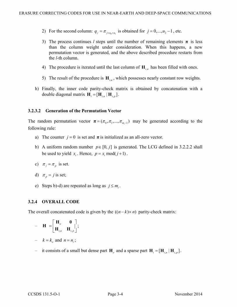
3.2.4 OVERALL CODE
The overall concatenated code is given by the (( ) )n k n− × parity-check matrix:
– , ,
o
i u i p
⎡ ⎤= ⎢ ⎥⎣ ⎦
H 0H
H H;
– ok k= and in n= ;
– it consists of a small but dense part oH and a sparse part , ,[ | ]i i u i p=H H H .
ERASURE CORRECTING CODES FOR USE IN NEAR-EARTH AND DEEP-SPACE COMMUNICATIONS
CCSDS 131.5-O-1 Page 3-5 November 2014
NOTES
1 The proposed F-IRA codes have the advantage that both outer and inner code parity-check matrices can be generated on the fly for various information and block lengths, where merely the inner code VN degree distribution Φ(x) has to be known.
2 To ensure flexibility also in the code rate, either different Φ(x) or different puncturing patterns have to be stored. In the latter case, periodic puncturing of the inner parity VNs; i.e., the VNs corresponding to the columns of ,i pH may be performed.
3.3 ENCODING
Encoding can be split up as follows:
a) The parity symbols associated with ,o pH are obtained simply as sum of the corresponding VNs in ,o uH .
NOTE – The complexity scales with ( )o o ok n k− . However, for high oR the number of parity checks ( )o on k− is kept low.
b) The parity symbols associated with ,i pH are obtained from the VNs associated with
,i uH based on the accumulator construction in (reference [G11]).
c) Each parity symbol associated with ,i pH is the sum of the VNs as defined by ,i uH plus another already-computed parity symbol of ,i pH .
NOTE – Because of the sparse nature of ,i uH , encoding is linear in ( )i in k− .
3.4 DISCUSSION—DECODING
Decoding of the concatenated scheme is done jointly by applying ML-P decoding on the
parity-check matrix of the concatenated code ,
, ,
,o
i u i p
⎡ ⎤= ⎢ ⎥⎣ ⎦
H 0H
H H. As described previously,
decoding consists of solving T =xH 0 , where some elements of x are affected by erasures after transmission over the channel. Although decoding complexity asymptotically scales with the cube of the block length, the sparse structure of H allows recovery of most of the unknowns iteratively.

ERASURE CORRECTING CODES FOR USE IN NEAR-EARTH AND DEEP-SPACE COMMUNICATIONS
CCSDS 131.5-O-1 Page 4-1 November 2014
4 AD-HOC CODE DESIGN
4.1 BACKGROUND
The F-IRA code design has the advantage of large flexibility in the choice of code parameters with minor performance losses with respect to the Singleton bound. In case such flexibility is not required or there is the possibility to store a number of predesigned parity-check matrices, the code performance may be further improved.
Therefore a new family of IRA codes has been designed: it is based on circulant permutation matrices for the ML-P decoder with different rates and block lengths. The code parameters for the different codes iC are summarized in table 4-1, where q is the circulant size and
/a m q= .
Table 4-1: Parameters for Proposed IRA Code Family
1
2
3
4
5
6
7
8
9
768 512 256 2 / 3 32 83072 2048 1024 2 / 3 128 824576 16384 8192 2 / 3 256 32640 512 128 4 / 5 16 82560 2048 512 4 / 5 64 8
20480 16384 4096 4 / 5 256 16576 512 64 8 / 9 8 82304 2048 256 8 / 9 32 8
18432 16384 2048 8 / 9 128 16
n k m R q aCCCCCCCCC
4.2 ENCODING
4.2.1 GENERAL
Encoding shall be performed in compliance with the DVB-S2 standard (reference [7]):
a) The encoder maps the information word 0 1 1[ , ,..., ]ku u u −=u of size k onto a codeword 0 1 1[ , ,..., ]nc c c −=c of size n , where the code is systematic; i.e., c is made up of the information symbols u and the parity symbols 0 1 1[ , ,..., ]mp p p −=p as
[ ]=c u | p .
b) Vector p can be calculated in an IRA-like fashion, by obtaining p from u as follows:
1) p is initialized as 0 1 1[ , ,..., ] [0,0,...,0]mp p p p −= = .

ERASURE CORRECTING CODES FOR USE IN NEAR-EARTH AND DEEP-SPACE COMMUNICATIONS
CCSDS 131.5-O-1 Page 4-2 November 2014
2) The first information bits are accumulated in u , i.e., 0u at parity bit addresses specified in the first row of the tables in 4.2.2.
NOTE – As an example, taking table 4-2 as reference, the following equations are obtained:
41 41 0
60 60 0
72 72 0
222 222 0
...
p p u
p p u
p p u
p p u
= ⊕
= ⊕
= ⊕
= ⊕
3) For the next 1q − information bits at the parity bits { }, 1,..., 1xu x q∈ − , xu are
accumulated at the parity bit addresses ( )mod mod , ,y x q a m+ ⋅⎡ ⎤⎣ ⎦ , where y denotes the address of the parity bit of the accumulator corresponding rows of the tables in 4.2.2. The parameter a has been defined previously in 4.1.
NOTE – To continue with the previous example and considering again table 4-2, for 1u the formula above yields:
49 49 1
68 68 1
80 80 1
230 230 1
...
p p u
p p u
p p u
p p u
= ⊕
= ⊕
= ⊕
= ⊕
4) In general, for the ( 1)z q− ⋅ -th information bit, the addresses of the parity bit accumulators are given in the z -th row of the tables in 4.2.2. The addresses of the parity bit accumulators for the following 1q − information bits
{ }, ( 1) 1,..., 1xg x z q z q∈ − ⋅ + ⋅ − are obtained using the formula
( )mod mod , ,y x q a m+ ⋅⎡ ⎤⎣ ⎦ as before.
5) After all information bits have been processed, the additions 1x x xp p p−= ⊕ are performed, where { }1,..., 1x m∈ − .

ERASURE CORRECTING CODES FOR USE IN NEAR-EARTH AND DEEP-SPACE COMMUNICATIONS
CCSDS 131.5-O-1 Page 4-3 November 2014
4.2.2 ACCUMULATOR INDICES
Table 4-2: Accumulator Indices for Code C1
41 60 72 98 222 33 112 163 197 255 2 46 67 116 248 90 117 129 151 243 156 162 198 208 213 15 113 155 196 245 55 68 86 136 234 33 46 149 203 231 2 76 120 225 254 95 112 133 179 185 54 76 146 232 251 107 159 177 245 250 116 146 157 198 240 28 93 113 159 195 15 144 186 188 246 15 27 41 69 150
NOTE – The z th row states that the ( 1)z q− ⋅ th bit in u contributes to the parity bits yp , with y being the indices in the table.
Table 4-3: Accumulator Indices for Code C2
33 204 222 645 730 760 80 243 481 541 639 900 251 464 697 710 754 980 43 229 288 505 671 100259 162 582 744 67 738 935 961 36 146 310 736 211 413 609 1023 6 124 666 768 91 121 565 943 506 576 812 902 385 495 619 645 368 468 498 870 59 253 737 1023 810 832 860 934 129 339 447 613
NOTE – The z th row states that the ( 1)z q− ⋅ th bit in u contributes to the parity bits yp , with y being the indices in the table.
ERASURE CORRECTING CODES FOR USE IN NEAR-EARTH AND DEEP-SPACE COMMUNICATIONS
CCSDS 131.5-O-1 Page 4-4 November 2014
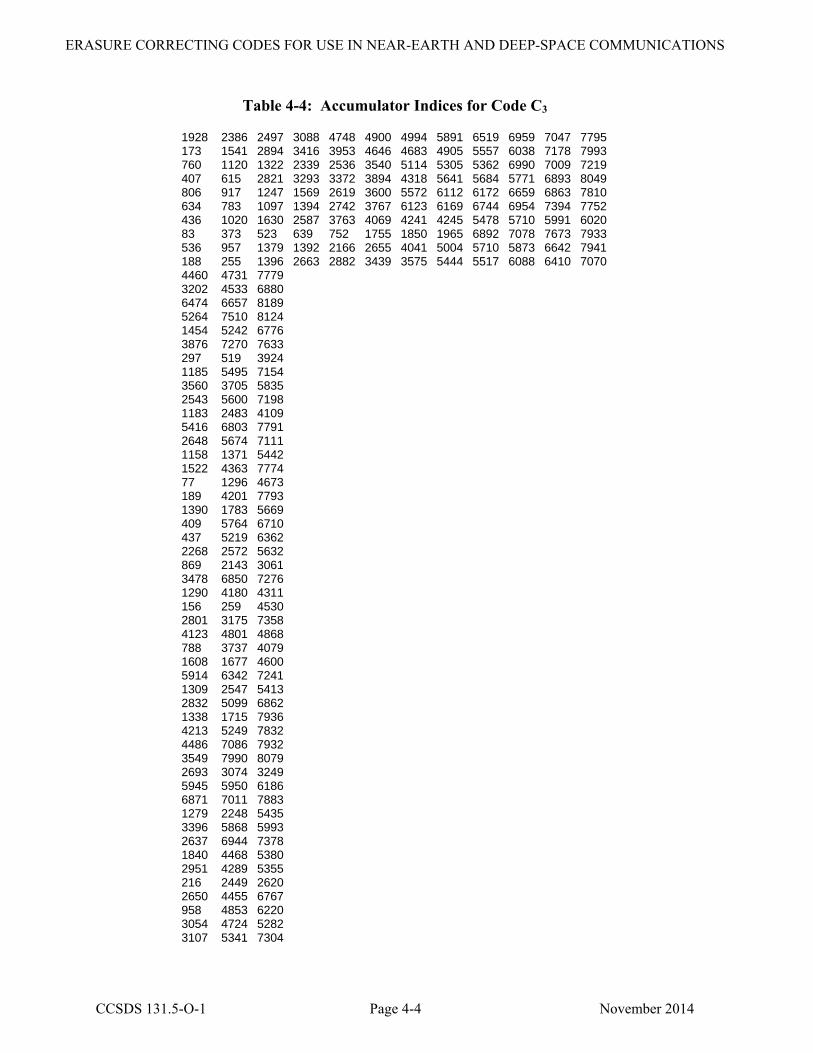
Table 4-4: Accumulator Indices for Code C3
1928 2386 2497 3088 4748 4900 4994 5891 6519 6959 7047 7795 173 1541 2894 3416 3953 4646 4683 4905 5557 6038 7178 7993 760 1120 1322 2339 2536 3540 5114 5305 5362 6990 7009 7219 407 615 2821 3293 3372 3894 4318 5641 5684 5771 6893 8049 806 917 1247 1569 2619 3600 5572 6112 6172 6659 6863 7810 634 783 1097 1394 2742 3767 6123 6169 6744 6954 7394 7752 436 1020 1630 2587 3763 4069 4241 4245 5478 5710 5991 6020 83 373 523 639 752 1755 1850 1965 6892 7078 7673 7933 536 957 1379 1392 2166 2655 4041 5004 5710 5873 6642 7941 188 255 1396 2663 2882 3439 3575 5444 5517 6088 6410 7070 4460 4731 7779 3202 4533 6880 6474 6657 8189 5264 7510 8124 1454 5242 6776 3876 7270 7633 297 519 3924 1185 5495 7154 3560 3705 5835 2543 5600 7198 1183 2483 4109 5416 6803 7791 2648 5674 7111 1158 1371 5442 1522 4363 7774 77 1296 4673 189 4201 7793 1390 1783 5669 409 5764 6710 437 5219 6362 2268 2572 5632 869 2143 3061 3478 6850 7276 1290 4180 4311 156 259 4530 2801 3175 7358 4123 4801 4868 788 3737 4079 1608 1677 4600 5914 6342 7241 1309 2547 5413 2832 5099 6862 1338 1715 7936 4213 5249 7832 4486 7086 7932 3549 7990 8079 2693 3074 3249 5945 5950 6186 6871 7011 7883 1279 2248 5435 3396 5868 5993 2637 6944 7378 1840 4468 5380 2951 4289 5355 216 2449 2620 2650 4455 6767 958 4853 6220 3054 4724 5282 3107 5341 7304
ERASURE CORRECTING CODES FOR USE IN NEAR-EARTH AND DEEP-SPACE COMMUNICATIONS
CCSDS 131.5-O-1 Page 4-5 November 2014
4934 6102 7602 266 3475 4379 2445 4025 5285 1312 4329 4791 4064 5919 6192
NOTE – The z th row states that the ( 1)z q− ⋅ th bit in u contributes to the parity bits yp , with y being the indices in the table.
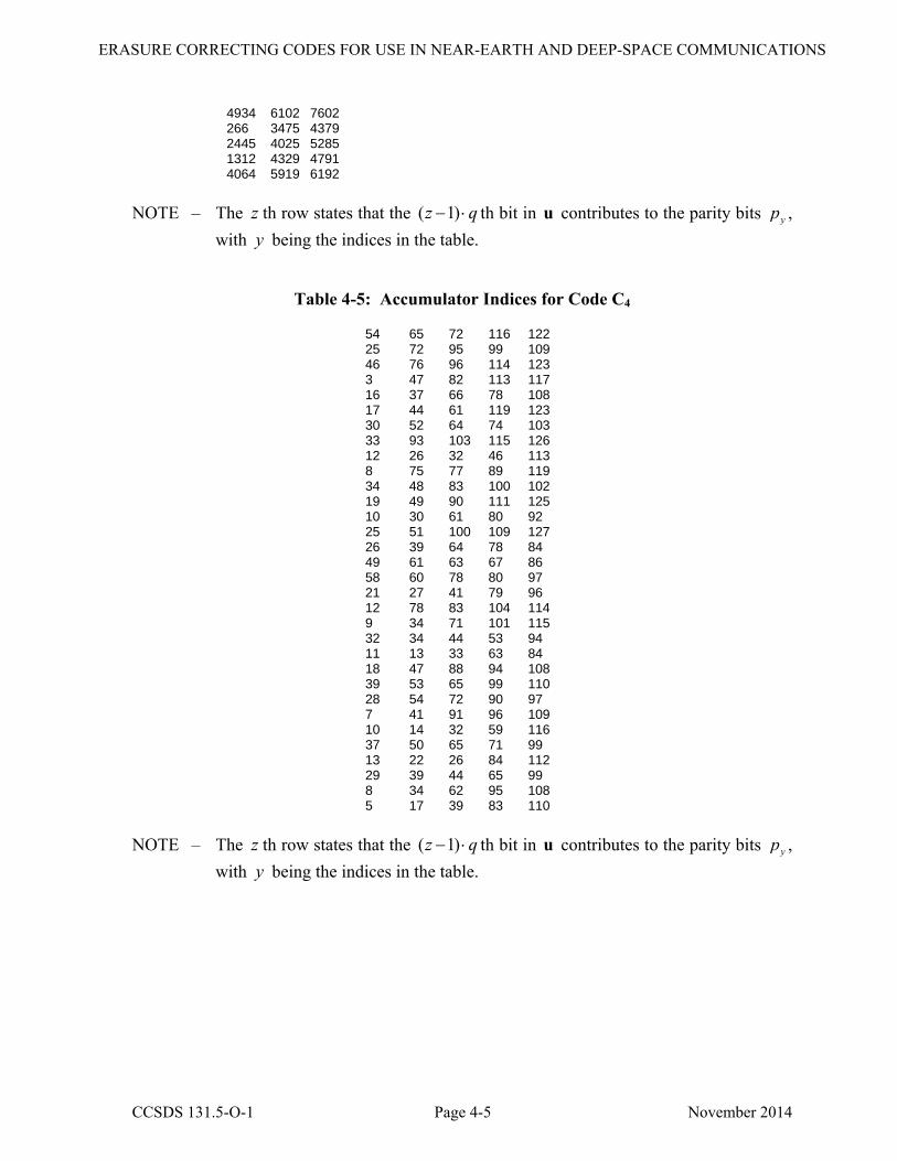
Table 4-5: Accumulator Indices for Code C4
54 65 72 116 122 25 72 95 99 109 46 76 96 114 123 3 47 82 113 117 16 37 66 78 108 17 44 61 119 123 30 52 64 74 103 33 93 103 115 126 12 26 32 46 113 8 75 77 89 119 34 48 83 100 102 19 49 90 111 125 10 30 61 80 92 25 51 100 109 127 26 39 64 78 84 49 61 63 67 86 58 60 78 80 97 21 27 41 79 96 12 78 83 104 114 9 34 71 101 115 32 34 44 53 94 11 13 33 63 84 18 47 88 94 108 39 53 65 99 110 28 54 72 90 97 7 41 91 96 109 10 14 32 59 116 37 50 65 71 99 13 22 26 84 112 29 39 44 65 99 8 34 62 95 108 5 17 39 83 110
NOTE – The z th row states that the ( 1)z q− ⋅ th bit in u contributes to the parity bits yp , with y being the indices in the table.
ERASURE CORRECTING CODES FOR USE IN NEAR-EARTH AND DEEP-SPACE COMMUNICATIONS
CCSDS 131.5-O-1 Page 4-6 November 2014
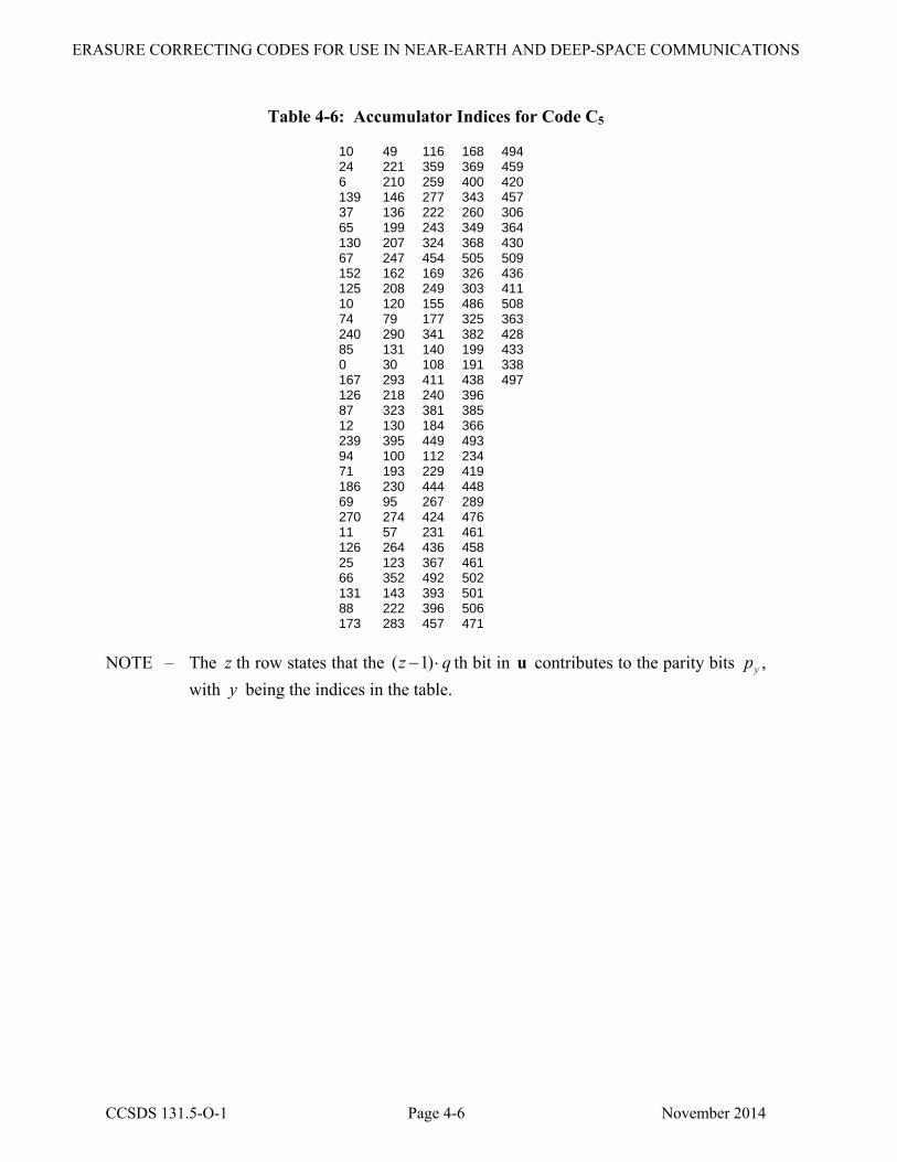
Table 4-6: Accumulator Indices for Code C5
10 49 116 168 494 24 221 359 369 459 6 210 259 400 420 139 146 277 343 457 37 136 222 260 306 65 199 243 349 364 130 207 324 368 430 67 247 454 505 509 152 162 169 326 436 125 208 249 303 411 10 120 155 486 508 74 79 177 325 363 240 290 341 382 428 85 131 140 199 433 0 30 108 191 338 167 293 411 438 497 126 218 240 396 87 323 381 385 12 130 184 366 239 395 449 493 94 100 112 234 71 193 229 419 186 230 444 448 69 95 267 289 270 274 424 476 11 57 231 461 126 264 436 458 25 123 367 461 66 352 492 502 131 143 393 501 88 222 396 506 173 283 457 471
NOTE – The z th row states that the ( 1)z q− ⋅ th bit in u contributes to the parity bits yp , with y being the indices in the table.

ERASURE CORRECTING CODES FOR USE IN NEAR-EARTH AND DEEP-SPACE COMMUNICATIONS
CCSDS 131.5-O-1 Page 4-7 November 2014
Table 4-7: Accumulator Indices for Code C6
726 752 850 1111 1173 1507 2299 2463 2474 2493 3020 3368 3518 3857 3972 405743 194 228 458 725 918 1311 1534 2903 3005 3219 3424 3692 3777 3945 396049 125 170 309 795 1135 1779 1938 2088 2684 2944 2996 3127 3350 3449 351872 490 533 589 1102 1428 1795 1929 2236 2559 2779 2880 3329 3538 3735 4086262 298 503 734 1488 1524 2060 2521 2783 3141 3227 3331 3506 3825 3912 3917179 406 889 994 1037 1217 1899 1903 2308 2421 2472 2698 3020 3216 3374 400743 84 263 670 777 908 1075 1152 2070 2077 2202 2450 2577 3029 3151 317628 79 101 126 809 1181 1234 1734 1745 2248 2260 2307 2554 2640 3639 4043164 888 992 3580 1 697 1565 1957 102 618 1118 1154 1095 1507 1999 3451 80 1772 2964 3832 201 1245 1361 3765 486 906 2706 3566 1571 1783 3023 4027 1900 3368 3812 661 2633 3581 862 1654 1738 619 1311 3975 272 1212 2264 1245 3833 3857 674 2762 3518 99 2283 3743 468 476 2416 301 1045 1105 998 1262 2322 1023 1463 3811 820 2304 3528 1337 2097 2389 586 3798 4066 7 707 3755 2052 3416 3436 405 521 717 778 1014 1054 455 479 2555 760 2348 4048 161 2185 2941 1042 3070 3226 387 1019 2159 1476 2172 3472 3069 3361 3605 114 358 2462 1203 1607 3423 660 1720 2944 949 3241 3713 66 470 778 931 1131 2951 392 2020 2444 2217 2725 2925 54 1966 3530 7 111 395 976 1612 2536 1469 3057 3465
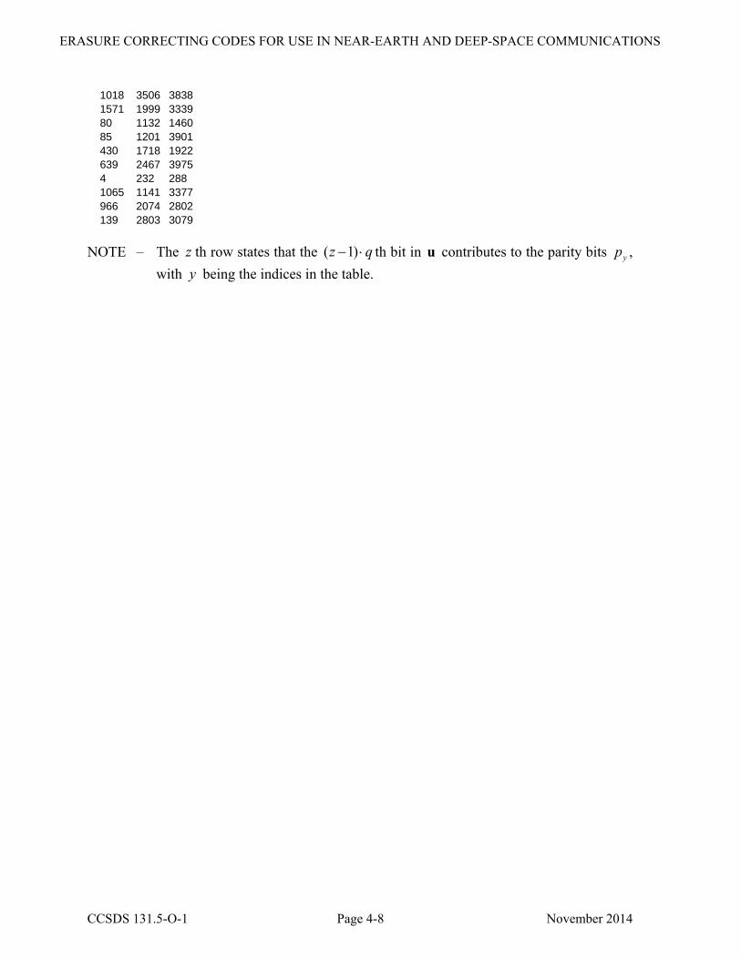
ERASURE CORRECTING CODES FOR USE IN NEAR-EARTH AND DEEP-SPACE COMMUNICATIONS
CCSDS 131.5-O-1 Page 4-8 November 2014
1018 3506 3838 1571 1999 3339 80 1132 1460 85 1201 3901 430 1718 1922 639 2467 3975 4 232 288 1065 1141 3377 966 2074 2802 139 2803 3079
NOTE – The z th row states that the ( 1)z q− ⋅ th bit in u contributes to the parity bits yp , with y being the indices in the table.
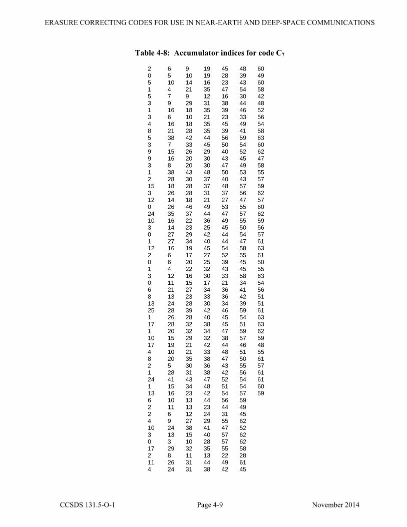
ERASURE CORRECTING CODES FOR USE IN NEAR-EARTH AND DEEP-SPACE COMMUNICATIONS
CCSDS 131.5-O-1 Page 4-9 November 2014
Table 4-8: Accumulator indices for code C7
2 6 9 19 45 48 60 0 5 10 19 28 39 49 5 10 14 16 23 43 60 1 4 21 35 47 54 58 5 7 9 12 16 30 42 3 9 29 31 38 44 48 1 16 18 35 39 46 52 3 6 10 21 23 33 56 4 16 18 35 45 49 54 8 21 28 35 39 41 58 5 38 42 44 56 59 63 3 7 33 45 50 54 60 9 15 26 29 40 52 62 9 16 20 30 43 45 47 3 8 20 30 47 49 58 1 38 43 48 50 53 55 2 28 30 37 40 43 57 15 18 28 37 48 57 59 3 26 28 31 37 56 62 12 14 18 21 27 47 57 0 26 46 49 53 55 60 24 35 37 44 47 57 62 10 16 22 36 49 55 59 3 14 23 25 45 50 56 0 27 29 42 44 54 57 1 27 34 40 44 47 61 12 16 19 45 54 58 63 2 6 17 27 52 55 61 0 6 20 25 39 45 50 1 4 22 32 43 45 55 3 12 16 30 33 58 63 0 11 15 17 21 34 54 6 21 27 34 36 41 56 8 13 23 33 36 42 51 13 24 28 30 34 39 51 25 28 39 42 46 59 61 1 26 28 40 45 54 63 17 28 32 38 45 51 63 1 20 32 34 47 59 62 10 15 29 32 38 57 59 17 19 21 42 44 46 48 4 10 21 33 48 51 55 8 20 35 38 47 50 61 2 5 30 36 43 55 57 1 28 31 38 42 56 61 24 41 43 47 52 54 61 1 15 34 48 51 54 60 13 16 23 42 54 57 59 6 10 13 44 56 59 2 11 13 23 44 49 2 6 12 24 31 45 4 9 27 29 55 62 10 24 38 41 47 52 3 13 15 40 57 62 0 3 10 28 57 62 17 29 32 35 55 58 2 8 11 13 22 28 11 26 31 44 49 61 4 24 31 38 42 45

ERASURE CORRECTING CODES FOR USE IN NEAR-EARTH AND DEEP-SPACE COMMUNICATIONS
CCSDS 131.5-O-1 Page 4-10 November 2014
9 19 44 46 53 63 16 20 39 49 58 62 25 40 46 59 61 63 1 40 43 50 60 62 2 23 29 33 48 59
NOTE – The z th row states that the ( 1)z q− ⋅ th bit in u contributes to the parity bits yp , with y being the indices in the table.
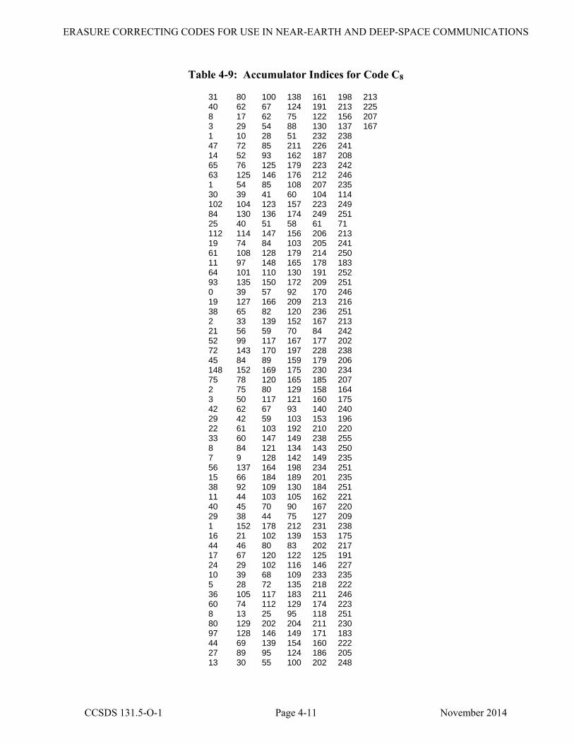
ERASURE CORRECTING CODES FOR USE IN NEAR-EARTH AND DEEP-SPACE COMMUNICATIONS
CCSDS 131.5-O-1 Page 4-11 November 2014
Table 4-9: Accumulator Indices for Code C8
31 80 100 138 161 198 213 40 62 67 124 191 213 225 8 17 62 75 122 156 207 3 29 54 88 130 137 167 1 10 28 51 232 238 47 72 85 211 226 241 14 52 93 162 187 208 65 76 125 179 223 242 63 125 146 176 212 246 1 54 85 108 207 235 30 39 41 60 104 114 102 104 123 157 223 249 84 130 136 174 249 251 25 40 51 58 61 71 112 114 147 156 206 213 19 74 84 103 205 241 61 108 128 179 214 250 11 97 148 165 178 183 64 101 110 130 191 252 93 135 150 172 209 251 0 39 57 92 170 246 19 127 166 209 213 216 38 65 82 120 236 251 2 33 139 152 167 213 21 56 59 70 84 242 52 99 117 167 177 202 72 143 170 197 228 238 45 84 89 159 179 206 148 152 169 175 230 234 75 78 120 165 185 207 2 75 80 129 158 164 3 50 117 121 160 175 42 62 67 93 140 240 29 42 59 103 153 196 22 61 103 192 210 220 33 60 147 149 238 255 8 84 121 134 143 250 7 9 128 142 149 235 56 137 164 198 234 251 15 66 184 189 201 235 38 92 109 130 184 251 11 44 103 105 162 221 40 45 70 90 167 220 29 38 44 75 127 209 1 152 178 212 231 238 16 21 102 139 153 175 44 46 80 83 202 217 17 67 120 122 125 191 24 29 102 116 146 227 10 39 68 109 233 235 5 28 72 135 218 222 36 105 117 183 211 246 60 74 112 129 174 223 8 13 25 95 118 251 80 129 202 204 211 230 97 128 146 149 171 183 44 69 139 154 160 222 27 89 95 124 186 205 13 30 55 100 202 248

ERASURE CORRECTING CODES FOR USE IN NEAR-EARTH AND DEEP-SPACE COMMUNICATIONS
CCSDS 131.5-O-1 Page 4-12 November 2014
68 71 118 121 243 253 23 25 146 150 180 200 0 9 83 135 174 189 104 156 210 233 235 246
NOTE – The z th row states that the ( 1)z q− ⋅ th bit in u contributes to the parity bits yp , with y being the indices in the table.

ERASURE CORRECTING CODES FOR USE IN NEAR-EARTH AND DEEP-SPACE COMMUNICATIONS
CCSDS 131.5-O-1 Page 4-13 November 2014
Table 4-10: Accumulator Indices for Code C9
893 1429 1578 174459 1318 1854 1873231 1263 1378 191235 137 716 182814 105 192 743 58 545 1471 1524101 700 715 1346179 422 429 904 639 1697 1815 19781236 1243 1324 165061 117 1160 1507318 544 665 678 270 311 1321 1442602 1103 1443 1556597 1052 1168 1851374 577 728 1853615 1370 1757 1888161 324 510 1707719 728 1090 1541889 1142 1555 186822 963 1244 18651258 1632 1927 2029990 1137 1931 1972130 447 1573 1912527 1191 1506 1642444 835 964 1979208 477 808 139738 1073 1118 1849891 1075 1116 189280 1416 1485 1733646 1489 1545 1742226 247 495 1018518 717 1153 1544295 553 798 1394303 308 1187 1626837 939 1388 1872548 652 777 1827522 1341 1733 1744219 286 422 833 775 786 840 111973 368 1022 165597 1039 1210 1460108 181 306 603 38 845 1096 1907140 357 1035 193640 657 1430 1597377 914 1623 1646147 879 906 1076187 812 978 1493358 1283 1832 1949617 775 800 1246271 340 1578 180963 1297 1494 1513876 914 1351 1546612 845 1155 1819869 920 1486 1856796 1059 1350 2043104 461 1472 19431012 1017 1489 1694

ERASURE CORRECTING CODES FOR USE IN NEAR-EARTH AND DEEP-SPACE COMMUNICATIONS
CCSDS 131.5-O-1 Page 4-14 November 2014
626 1002 1045 1455661 1485 1635 184822 608 1454 176997 631 1343 1786290 444 788 157944 810 1573 184277 374 379 435 896 1160 1463 16781167 1489 1572 1737504 1265 1271 1789478 916 1337 1570307 698 767 12851195 1280 1388 1926751 1908 1929 200153 106 370 1116342 1053 1235 1371263 270 768 1656265 406 1087 1571151 224 268 842 100 145 251 1917130 872 1477 1758469 720 938 105386 161 270 1131383 568 823 1346188 281 291 11241247 1377 1402 1415780 1323 1458 1684152 445 659 165394 294 633 1920305 621 699 1142584 926 962 1479457 1348 1427 1631140 1018 1141 148829 406 1339 1521350 408 1271 1954175 249 1620 1795133 240 300 1882138 669 704 791 734 1339 1585 1972543 869 872 1266550 636 1331 18651518 1792 1863 2040297 1055 1825 2004426 604 1170 1205219 310 717 1347351 614 713 963 759 1036 1056 1786305 308 1181 138788 418 814 1301838 1197 1523 1899158 727 1136 1496225 665 1135 142812 746 1138 120544 52 579 1497426 1341 1685 1760699 1158 1582 1985354 1112 1527 1887919 1312 1354 140520 427 862 1345610 735 936 1365153 355 796 12068 383 1491 1926

ERASURE CORRECTING CODES FOR USE IN NEAR-EARTH AND DEEP-SPACE COMMUNICATIONS
CCSDS 131.5-O-1 Page 4-15 November 2014
172 480 663 1833202 337 1556 1997482 939 1445 151813 165 1427 1770336 715 958 1078159 1080 1105 1367377 564 860 1010
NOTE – The z th row states that the ( 1)z q− ⋅ th bit in u contributes to the parity bits yp , with y being the indices in the table.
ERASURE CORRECTING CODES FOR USE IN NEAR-EARTH AND DEEP-SPACE COMMUNICATIONS
CCSDS 131.5-O-1 Page 5-1 November 2014
5 ERASURE CODING PROTOCOL
5.1 OVERVIEW
The erasure coding schemes detailed in sections 3 and 4 are to be implemented as part of a dedicated erasure coding protocol. The protocol is to be implemented within a shim layer positioned above the CCSDS Encapsulation Service (see also figure 2-6), so as to improve the transmission robustness of LTP segments and bundles. This choice is determined by the necessity to implement erasure codes as close as possible to CCSDS Space Data Link Protocol (SDLP) layers, where actually transfer frame erasures originate and are detected. Further, such a positioning allows avoiding or at least limiting (depending on erasure decoding success/failure) the propagation of information erasures upwards in the CCSDS protocol stack and, in general, throughout the rest of the space network.
For LTP segments containing red-parts, the use of erasure codes complements the ARQ mechanisms used by the LTP protocol entity to recover the missing LTP segments by retransmission. For LTP segments containing green-parts, the use of erasure codes provides a higher reliability at a cost of limited increases in delivery time and bandwidth.
Similar considerations apply to the case where BP is configured with the custody transfer option enabled: the ARQ strategy implemented by the BP layer is complemented by the erasure coding functions implemented in the shim layer.
The SDU of the EC Service is the ADU received from the upper protocol layer, such as LTP, BP, IPoC, or CFDP: an LTP segment, a bundle, an IP datagram, or CFDP PDU respectively.
The PDU of the EC Service is the ECDU generated during the erasure coding process at the sender side and submitted to the erasure decoding process at the receiver side.
The interaction of the EC Service with the other adjacent layers of the CCSDS protocol stack is depicted in figure 5-1.

ERASURE CORRECTING CODES FOR USE IN NEAR-EARTH AND DEEP-SPACE COMMUNICATIONS
CCSDS 131.5-O-1 Page 5-2 November 2014
Figure 5-1: Layered Approach for Implementing Erasure Codes
Implementation of the EC shim layer on top of the CCSDS Encapsulation Service (reference [3]) introduces some requirements on the SAP defined between the shim layer and the CCSDS Encapsulation Packet or SPP.
In order for the Encapsulation Service to multiplex SDUs originating from different protocols, specific identifiers are defined in the Encapsulation Packet header:
– Packet Version Number (‘001’ for Space Packets and ‘111’ for Encapsulation Packet);
– Encapsulation Protocol Identifier:
• Application Process IDentifier (APID) (0-2043 available) in case of encapsulation of Space Packets;
• Protocol Identifiers (100 and 101 available) in case of encapsulation of non-Space Packets;
• Extended Protocol Identifiers (0000 through 1111 still available) in case of encapsulation of non-Space Packets when the Protocol Identifier is set to ‘110’.
As a consequence, the ECDUs generated by the EC shim layer need to be properly encapsulated in Space or Encapsulation Packets.
According to the experimental nature of this CCSDS Specification, space agencies are invited to use as Managed Parameters:

ERASURE CORRECTING CODES FOR USE IN NEAR-EARTH AND DEEP-SPACE COMMUNICATIONS
CCSDS 131.5-O-1 Page 5-3 November 2014
– Protocol Identifier ‘111’ (Arbitrary Aggregation of Octets) when Encapsulation Packet is applicable; and
– a value of the Application Process Identifier (APID) in the range 0–2039 (i.e., values not reserved by CCSDS) when SPP is applicable.
5.2 ARCHITECTURAL ELEMENTS
5.2.1 The erasure coding and decoding functionalities shall be implemented in the erasure coding protocol entity with respect to:
– the sender peer shall get the ADUs (LTP segments or bundles) from the upper layer as input and generate the ECDUs (according to encoding algorithms documented in sections 3 and 4);
– the receiver peer shall reconstruct by means of erasure decoding algorithms the ADUs that were erased during the transmission over the space links.
5.2.2 The encoding (decoding) protocol entity shall comprise the following elements:
– encoding matrix;
– encoding (decoding) engine, which carries out the encoding (decoding) processes, according to the algorithms and the parity check matrices defined in sections 3 and 4 above;
NOTE – The encoding process takes as input the ADUs, which are copied in the encoding matrix for the consequent generation of redundancy symbols, referred to as data redundancy units.
– protocol engine, which processes the native ADUs and the generated DRUs and performs the packetization service consisting in the composition of ECDUs, to be forwarded to the CCSDS Encapsulation Service.
NOTES
1 Description of the protocol procedures for both sending and receiving sides is provided in 5.4.2.
2 The overall protocol architecture is depicted in figure 5-2.

ERASURE CORRECTING CODES FOR USE IN NEAR-EARTH AND DEEP-SPACE COMMUNICATIONS
CCSDS 131.5-O-1 Page 5-4 November 2014
Figure 5-2: Diagram of the Erasure Coding Protocol Entity
5.3 EC SERVICE DEFINITION
5.3.1 OVERVIEW
This subsection provides the definition of the erasure coding in the form of primitives, which present an abstract model of the logical exchange of data and control information between the service provider and the service user. The definitions of primitives are independent of specific implementation approaches.
The parameters of the primitives are specified in an abstract sense and specify the information to be made available to the user of the primitive. The way in which a specific implementation makes this information available is not constrained by this specification. In addition to the parameters specified in this subsection, an implementation may provide other parameters to the service user (e.g., parameters for controlling the service, monitoring performance, facilitating diagnosis, and so on).

ERASURE CORRECTING CODES FOR USE IN NEAR-EARTH AND DEEP-SPACE COMMUNICATIONS
CCSDS 131.5-O-1 Page 5-5 November 2014
5.3.2 SERVICE INTERFACES
5.3.2.1 The erasure coding protocol shim layer shall implement two interfaces:
– upward to the LTP and Bundle Protocol CLAs. The upward interface exchanges ADUs with the layer above:
• in the case of the sender peer, the ADUs correspond to LTP segments generated by the corresponding LTP client instance, or to bundles;
• in the case of the receiver peer, the ADUs correspond to LTP segments (recovered or possibly partly erased in case of unsuccessful decoding) or the bundles, to be forwarded to the LTP server instance, or to the BP CLA respectively;
– downward to the CCSDS Encapsulation Service. The downward interface exchanges ECDUs with the layer below:
• in the case of the sender peer, the ECDUs are the output of the erasure coding protocol entity and are forwarded to the lower layer for further transport in Encapsulation or Space Packets.
• in the case of the receiver peer, ECDUs (some possibly erased in part) are forwarded from the CCSDS Encapsulation Service to the EC shim layer for eventual processing, to be carried out by the protocol engine.
5.3.2.2 There exist two SAPs corresponding to the interfaces defined in 5.3.2.1:
– the SAP between the EC shim layer and the layer above shall provide the primitives detailed in 5.3.5 to enable the exchange of data between the two layers;
– the SAP between the EC shim layer and the layer below shall use the request and indication primitives defined by the CCSDS Encapsulation Service and the SPP:
• CCSDS Encapsulation Service:
ENCAPSULATION.request (Data Unit, SDLP_CHANNEL, PVN, EPI)
ENCAPSULATION.indication (Data Unit, SDLP_CHANNEL, PVN, EPI, Data Unit Loss Flag (optional));
• SPP:
PACKET.request (Space Packet, APID, APID Qualifier (optional), QoS Requirement (optional))
PACKET.indication (Space Packet, APID, APID Qualifier (optional)).

ERASURE CORRECTING CODES FOR USE IN NEAR-EARTH AND DEEP-SPACE COMMUNICATIONS
CCSDS 131.5-O-1 Page 5-6 November 2014
5.3.3 SUMMARY OF PRIMITIVES
The EC Service shall provide the following primitives:
– EC_Send.request. The EC_Send.request primitive shall be passed from the EC Service user at the sending end to the service provider to request the EC function and transfer to the SDLP via the suited Encapsulation Service.
– EC_Receive.indication. The EC_Receive.indication shall be passed from the service provider to the EC Service user at the receiving end in order to deliver an ADU as soon as the erasure decoding process is successfully completed.
5.3.4 SUMMARY OF PARAMETERS
The data unit parameter is the SDU transferred by the EC Service:
– it shall contain a delimited, octet-aligned ADU;
– the maximum length of an ADU accommodated by this service shall be constrained by the maximum SDU size of the underlying layer (Encapsulation Packet or SPP) minus the size of the EC Header used by this service.
NOTE – Although the maximum length of a data unit that can be accommodated in an encapsulating packet is 65,536 octets (if the Space Packet is used) or 4,294,967,287 octets (if the Encapsulation Packet is used), individual project organizations may establish the maximum and minimum sizes for the encapsulated data unit.
The SAP_Address parameter shall indicate the EC SAP at which the service primitive is enacted and shall contain the following fields in the following order:
– SDLP_Channel is part of the SAP address of the Encapsulation Service. It uniquely identifies the channel of the underlying SDLP through which the Data Unit is to be transferred. Reference [3] describes the SDLP_Channel semantics; the exact semantics depend on the underlying SDLP services;
– PVN is part of the SAP address of the Encapsulation Service and is the Packet Version Number (of the Encapsulation Service, either Encapsulation or CCSDS Packet);
– EPI is part of the SAP address of the Encapsulation Service; depending on the protocol used to implement the Encapsulation Service, the EPI is either an APID or the Protocol Identifier.

ERASURE CORRECTING CODES FOR USE IN NEAR-EARTH AND DEEP-SPACE COMMUNICATIONS
CCSDS 131.5-O-1 Page 5-7 November 2014
5.3.5 SERVICE PRIMITIVES
5.3.5.1 EC_Send.request
5.3.5.1.1 Function
The EC_Send.request primitive shall be the service request primitive for the EC Service.
5.3.5.1.2 Semantics
EC_Send.request shall provide parameters as follows:
EC_Send.request (Unit Data, SAP_address)
5.3.5.1.3 When Generated
The EC_Send.request primitive shall be passed to the service provider to request it to perform erasure coding on the Data Unit.
5.3.5.1.4 Effect on Reception
Receipt of the EC_Send.request primitive shall cause the service provider to perform erasure coding functions and transfer the Data Unit.
5.3.5.1.5 Additional Comments
None.

ERASURE CORRECTING CODES FOR USE IN NEAR-EARTH AND DEEP-SPACE COMMUNICATIONS
CCSDS 131.5-O-1 Page 5-8 November 2014
5.3.5.2 EC_Receive.indication
5.3.5.2.1 Function
The EC_Receive.indication primitive shall be the service indication primitive for the EC Service.
5.3.5.2.2 Semantics
EC_Receive.indication shall provide parameters as follows:
EC_Receive.indication (Unit Data, SAP_address)
5.3.5.2.3 When Generated
The EC_Receive.indication primitive shall be passed from the service provider to the EC Service user at the receiving end in order to deliver a Data Unit once the erasure decoding is performed successfully.
5.3.5.2.4 Effect On Receipt
The effect on receipt of the EC_Receive.indication primitive by the EC Service user is undefined.
5.3.5.2.5 Additional Comments
None.

ERASURE CORRECTING CODES FOR USE IN NEAR-EARTH AND DEEP-SPACE COMMUNICATIONS
CCSDS 131.5-O-1 Page 5-9 November 2014
5.4 PROTOCOL SPECIFICATION
5.4.1 PROTOCOL-DATA-UNIT
5.4.1.1 The ECDU is the fundamental PDU of the erasure coding layer. It shall encompass the major fields, positioned contiguously, in the following sequence:
– EC Header. The header of the ECDU, which shall encompass the major fields, positioned contiguously, in the following sequence:
• Version. Version of the erasure coding protocol;
• Protocol ID. Identifier of the protocol working on top of the erasure coding protocol layer;
• Reserved;
• Extensions count. Counter of the number of extensions that follow the header;
• LW Counter (LWC). Identifier of the LW corresponding to the encoding matrix row;
• LS Counter (LSC). Identifier of the encoding block to which each generated LS belongs;
• Extension header. Header defining a specific extension;
NOTE – A succession of multiple extensions header is possible, depending on the value of the extension count field.
– LS. The data units forwarded by the encoding engine;
– CRC-32 code. A CRC-32 validation code computed over the two previous fields (EC Header and LS) according to reference [6].
5.4.1.2 The lengths and values of the EC Header fields are specified in table 5-1.
Table 5-1: EC Header Specification
Field Length (bits) Values Comment Version 4 0 reserved 1 is the current version Protocol ID 3 - Identifier according to reference [4] Reserved 1 0 Extension Count 8 0 and 256 are reserved, 1-255 are
available Number of possible extensions that follow at the end of the header
LW Counter 16 0 and 65535 are reserved Identifies the encoding matrix LS Counter 16 0 and 65535 are reserved Identifies the position within the
encoding matrix Header Extensions variable - (See next table.)
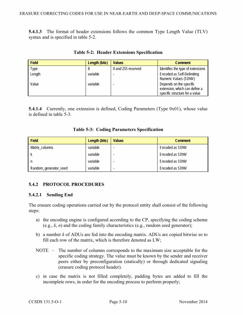
ERASURE CORRECTING CODES FOR USE IN NEAR-EARTH AND DEEP-SPACE COMMUNICATIONS
CCSDS 131.5-O-1 Page 5-10 November 2014
5.4.1.3 The format of header extensions follows the common Type Length Value (TLV) syntax and is specified in table 5-2.
Table 5-2: Header Extensions Specification
Field Length (bits) Values Comment Type 8 0 and 255 reserved Identifies the type of extensions Length variable - Encoded as Self-Delimiting
Numeric Values (SDNV) Value variable - Depends on the specific
extension, which can define a specific structure for a value
5.4.1.4 Currently, one extension is defined, Coding Parameters (Type 0x01), whose value is defined in table 5-3.
Table 5-3: Coding Parameters Specification
Field Length (bits) Values Comment Matrix_columns variable - Encoded as SDNV k variable - Encoded as SDNV n variable - Encoded as SDNV Random_generator_seed variable - Encoded as SDNV
5.4.2 PROTOCOL PROCEDURES
5.4.2.1 Sending End
The erasure coding operations carried out by the protocol entity shall consist of the following steps:
a) the encoding engine is configured according to the CP, specifying the coding scheme (e.g., k, n) and the coding family characteristics (e.g., random seed generator);
b) a number k of ADUs are fed into the encoding matrix. ADUs are copied bitwise so to fill each row of the matrix, which is therefore denoted as LW;
NOTE – The number of columns corresponds to the maximum size acceptable for the specific coding strategy. The value must be known by the sender and receiver peers either by preconfiguration (statically) or through dedicated signaling (erasure coding protocol header).
c) in case the matrix is not filled completely, padding bytes are added to fill the incomplete rows, in order for the encoding process to perform properly;

ERASURE CORRECTING CODES FOR USE IN NEAR-EARTH AND DEEP-SPACE COMMUNICATIONS
CCSDS 131.5-O-1 Page 5-11 November 2014
d) each LW is given a dedicated counter, LWC to be used afterwards for signaling purposes;
e) a number n-k DRUs are generated according to the selected coding strategy applied to the data stored in the encoding matrix;
f) the native k ADUs and the generated n-k DRUs, generally termed LSes, are assigned a common counter that uniquely identifies the set of LSes generated during that specific encoding round;
g) LSes are forwarded to the protocol engine, which appends to each of them the EC Header, carrying the information necessary (e.g., LWC, LSC, CP) to the receiver peer decoding engine to correctly perform the decoding process;
h) a CRC-32 code is computed on each data unit constructed at step 6, composed of EC Header and LS, and eventually appended as trailer;
i) the newly generated data units constructed at step 8 are termed erasure coding data units and are forwarded to the underlying layer.
NOTE – Overall protocol procedures at the sending side are depicted in figure 5-3.
ADU 1 ADU 2 ... ADU k
ADU 1 ADU 2 ...ADU k
DRU 1
DRU 2 DRU n‐k...
ADU 1H CRC ADU 2H CRC ADU kH CRC... H CRC DRU 2H CRC
DRU 1
DRU n‐kH CRC...
ECDU 1 ECDU 2 ECDU k ECDU k+1 ECDU k+2 ECDU n......
EC Service User
EC Service Provider
Erasure CodingProcess
Packetization
ADU fetching
NOTE – ‘H’ stands for EC Header and ‘CRC’ refers to CRC-32.
Figure 5-3: Erasure Coding Process Description
5.4.2.2 Receiving End
The erasure decoding operations carried out by the protocol entity shall consist of the following steps:
a) a number t of ECDUs are received by the erasure decoding protocol entity;
b) the protocol engine processes the EC Header and forwards the information therein contained to the decoding engine in order to eventually start the decoding procedure;
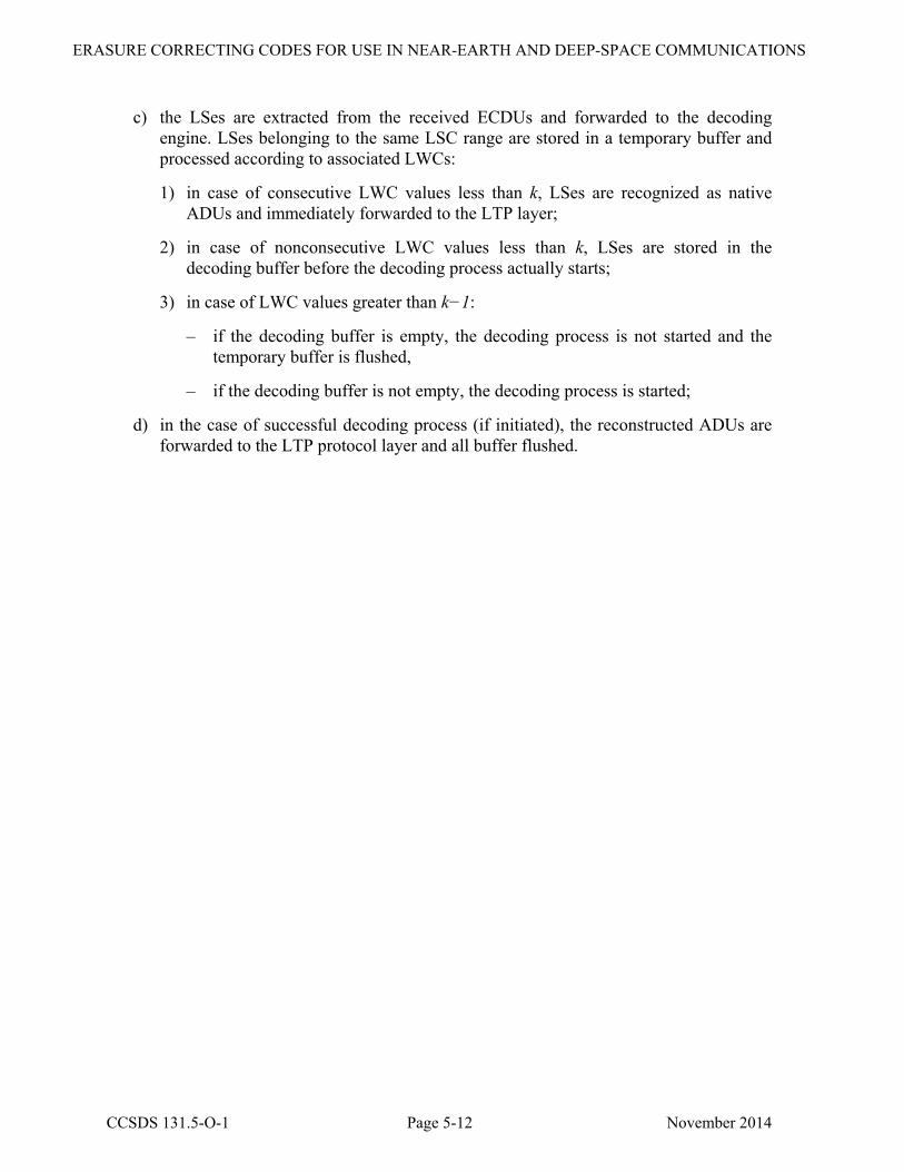
ERASURE CORRECTING CODES FOR USE IN NEAR-EARTH AND DEEP-SPACE COMMUNICATIONS
CCSDS 131.5-O-1 Page 5-12 November 2014
c) the LSes are extracted from the received ECDUs and forwarded to the decoding engine. LSes belonging to the same LSC range are stored in a temporary buffer and processed according to associated LWCs:
1) in case of consecutive LWC values less than k, LSes are recognized as native ADUs and immediately forwarded to the LTP layer;
2) in case of nonconsecutive LWC values less than k, LSes are stored in the decoding buffer before the decoding process actually starts;
3) in case of LWC values greater than k−1:
– if the decoding buffer is empty, the decoding process is not started and the temporary buffer is flushed,
– if the decoding buffer is not empty, the decoding process is started;
d) in the case of successful decoding process (if initiated), the reconstructed ADUs are forwarded to the LTP protocol layer and all buffer flushed.

ERASURE CORRECTING CODES FOR USE IN NEAR-EARTH AND DEEP-SPACE COMMUNICATIONS
CCSDS 131.5-O-1 Page A-1 November 2014
ANNEX A
PROTOCOL IMPLEMENTATION CONFORMANCE STATEMENT PROFORMA
(NORMATIVE)
A1 OVERVIEW
This annex provides the Protocol Implementation Conformance Statement (PICS) Requirements List (RL) for CCSDS-compliant implementations of the encoding protocol recommended in this document. The PICS for an implementation is generated by completing the RL in accordance with the instructions below. An implementation shall satisfy the mandatory conformance requirements of the base standards referenced in the RL.
An implementation’s completed RL is called the PICS. The PICS states which capabilities and options of the protocol have been implemented. The following can use the PICS:
a) the protocol implementer, as a checklist to reduce the risk of failure to conform to the specification through oversight;
b) the supplier and acquirer or potential acquirer of the implementation, as a detailed indication of the capabilities of the implementation, stated relative to the common basis for understanding provided by the standard PICS proforma;
c) the user or potential user of the implementation, as a basis for initially checking the possibility of interworking with another implementation (it should be noted that, while interworking can never be guaranteed, failure to interwork can often be predicted from incompatible PICSes);
d) a protocol tester, as the basis for selecting appropriate tests against which to assess the claim for conformance of the implementation.
A2 INSTRUCTIONS FOR COMPLETING THE RL
An implementer shows the extent of compliance to the protocol by completing the RL; that is, compliance to all mandatory requirements and the options that are not supported are shown. The resulting completed RL is called a PICS. In the Support column, each response shall be selected either from the indicated set of responses, or it shall comprise one or more parameter values as requested. If a conditional requirement is inapplicable, N/A should be used. If a mandatory requirement is not satisfied, exception information must be supplied by entering a reference Xi, where i is a unique identifier, to an accompanying rationale for the noncompliance. When the requirement is expressed as a two-character combination (as defined below), the response shall address each element of the requirement; e.g., for the requirement ‘MO’, the possible compliant responses are ‘YY’ or ‘YN’.

ERASURE CORRECTING CODES FOR USE IN NEAR-EARTH AND DEEP-SPACE COMMUNICATIONS
CCSDS 131.5-O-1 Page A-2 November 2014
A3 NOTATION
A3.1 The following symbols are used in the RL to indicate the status of features:
Table A-1: PICS Notation
Symbol Meaning M Mandatory
M.<n> Support of every item of the group labeled by the same number <n> required, but only one is active at a time
O Optional O.<n> Optional, but support of at least one of the group of options labeled by the
same numeral <n> is required C Conditional -- Non-applicable field/function (i.e., logically impossible in the scope of the
RL) I Out of scope of the RL (left as an implementation choice) X Excluded or prohibited
A3.2 Two-character combinations may be used for dynamic conformance requirements. In this case, the first character refers to the static (implementation) status, and the second refers to the dynamic (use) status; thus ‘MO’ means ‘mandatory to be implemented, optional to be used’.
A3.3 The following notations for conditional status shall be used:
Table A-2: PICS Conditional Status Notation
Symbol Meaning
<predicate>::
This notation introduces a group of items, all of which are conditional on <predicate>.
<predicate>: This notation introduces a single item which is conditional on <predicate>.
<index>: This notation indicates that the status following it applies only when the PICS states that the features identified by the index are supported. In the simplest
case, <index> is the identifying tag of a single RL item. The symbol <index> also may be a Boolean expression composed of several indices.
<index>:: This notation indicates that the associated clause should be completed.
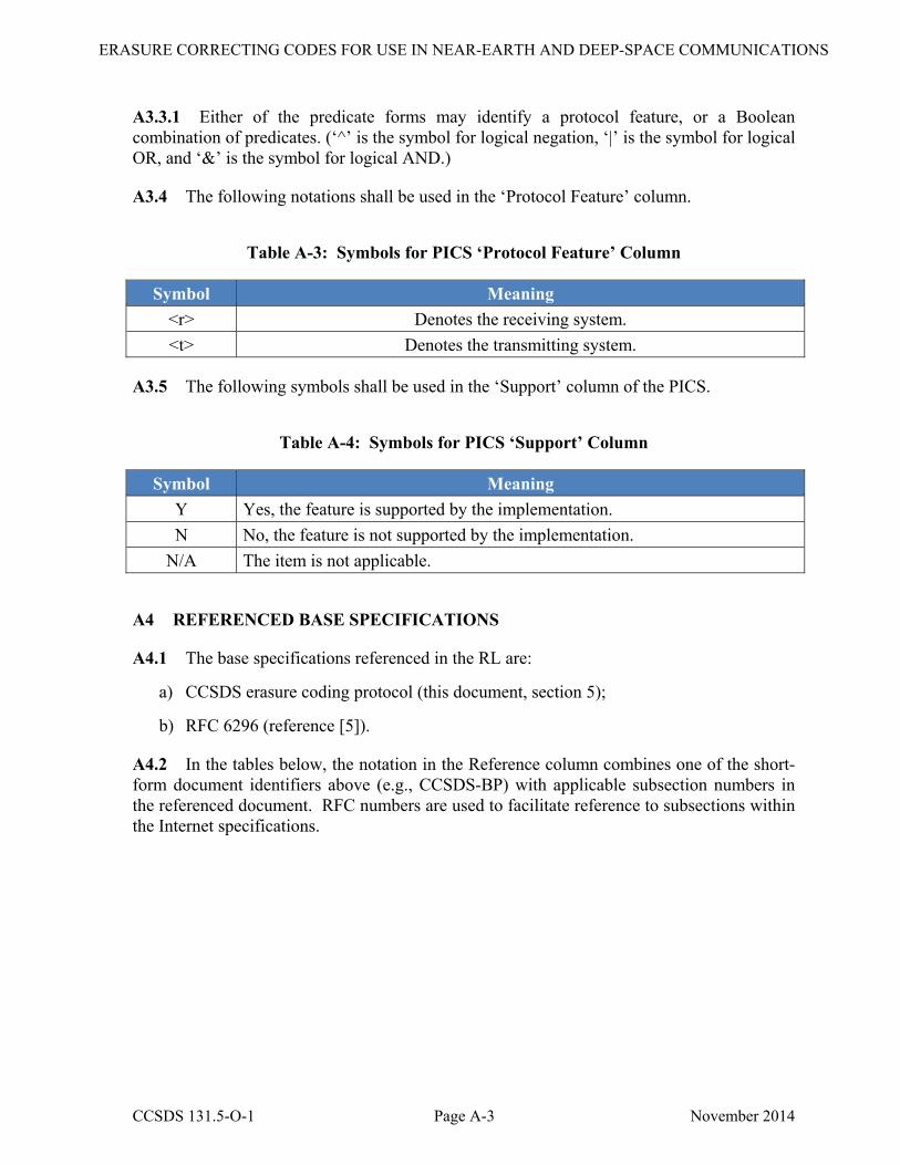
ERASURE CORRECTING CODES FOR USE IN NEAR-EARTH AND DEEP-SPACE COMMUNICATIONS
CCSDS 131.5-O-1 Page A-3 November 2014
A3.3.1 Either of the predicate forms may identify a protocol feature, or a Boolean combination of predicates. (‘^’ is the symbol for logical negation, ‘|’ is the symbol for logical OR, and ‘&’ is the symbol for logical AND.)
A3.4 The following notations shall be used in the ‘Protocol Feature’ column.
Table A-3: Symbols for PICS ‘Protocol Feature’ Column
Symbol Meaning <r> Denotes the receiving system. <t> Denotes the transmitting system.
A3.5 The following symbols shall be used in the ‘Support’ column of the PICS.
Table A-4: Symbols for PICS ‘Support’ Column
Symbol Meaning Y Yes, the feature is supported by the implementation. N No, the feature is not supported by the implementation.
N/A The item is not applicable.
A4 REFERENCED BASE SPECIFICATIONS
A4.1 The base specifications referenced in the RL are:
a) CCSDS erasure coding protocol (this document, section 5);
b) RFC 6296 (reference [5]).
A4.2 In the tables below, the notation in the Reference column combines one of the short-form document identifiers above (e.g., CCSDS-BP) with applicable subsection numbers in the referenced document. RFC numbers are used to facilitate reference to subsections within the Internet specifications.

ERASURE CORRECTING CODES FOR USE IN NEAR-EARTH AND DEEP-SPACE COMMUNICATIONS
CCSDS 131.5-O-1 Page A-4 November 2014
A5 GENERAL INFORMATION
A5.1 IDENTIFICATION OF PICS
Ref Question Response 1 Date of Statement (DD/MM/YYYY) 2 PICS serial number 3 System conformance statement cross-
reference
A5.2 IDENTIFICATION OF IMPLEMENTATION UNDER TEST (IUT)
Ref Question Response 1 Implementation name 2 Implementation version 3 Name of hardware (machine) used in
test
4 Version of hardware (machine) used in test
5 Name of operating system used during test
6 Version of operating system used during test
7 Additional configuration information pertinent to the test
8 Other information
A5.3 IDENTIFICATION
Ref Question Response 1 Supplier 2 Point of contact for queries 3 Implementation name(s) and version(s) 4 Other information necessary for full
identification (e.g., name(s) and version(s) for machines and/or operating systems

ERASURE CORRECTING CODES FOR USE IN NEAR-EARTH AND DEEP-SPACE COMMUNICATIONS
CCSDS 131.5-O-1 Page A-5 November 2014
A5.4 PROTOCOL SUMMARY
Ref Question Response 1 Protocol version 2 Addenda implemented 3 Amendments implemented 4 Have any exceptions been required?
NOTE – A YES answer means that the implementation does not conform to the protocol. Non-supported mandatory capabilities are to be identified in the PICS, with an explanation of why the implementation is non-conforming.
a) Yes b) No
5 Date of statement (DD/MM/YYYY)
A6 BASIC REQUIREMENTS
Item Protocol Feature Reference Status Support
SDNV SDNV Section 2 of reference [5] M EC Header This document: 5.4.1 M
Header Extensions This document: 5.4.1 M
Coding Parameters This document: 5.4.1 M

ERASURE CORRECTING CODES FOR USE IN NEAR-EARTH AND DEEP-SPACE COMMUNICATIONS
CCSDS 131.5-O-1 Page B-1 November 2014
ANNEX B
SECURITY AND PATENTS CONSIDERATIONS
(INFORMATIVE)
B1 INTRODUCTION
Security issues can indirectly affect the effectiveness of the long erasure codes implementation. Because long erasure codes are implemented in a separated shim layer, located beneath the LTP protocol layer, which is responsible only for encoding and decoding functions, security functions have to be implemented within the CCSDS protocols, (e.g., SDLP, LTP and BP).
B2 SECURITY CONCERNS WITH RESPECT TO THE CCSDS DOCUMENT
B2.1 DATA PRIVACY
This specification does not provide any mechanism to ensure data privacy. Any such mechanisms, if they are needed by missions, must be applied at other layers of the stack.
B2.2 DATA INTEGRITY
Data integrity is insured by dedicated CRC implemented within the shim layer.
B2.3 AUTHENTICATION OF COMMUNICATING ENTITIES
This specification does not provide any mechanism to ensure authentication of communication entities. Any such mechanisms, if they are needed by missions, must be applied at other layers of the stack.
NOTE – LTP-for-CCSDS allows the use of the LTP authentication mechanisms defined in RFC 5327.
B2.4 CONTROL OF ACCESS TO RESOURCES
This document assumes that control of access to resources is managed by the systems executing the protocol. No provisions are made by the protocol described in this document to limit or control access to resources (e.g., CPU, storage, or bandwidth) used by the protocol.
ERASURE CORRECTING CODES FOR USE IN NEAR-EARTH AND DEEP-SPACE COMMUNICATIONS
CCSDS 131.5-O-1 Page B-2 November 2014
B2.5 AVAILABILITY OF RESOURCES
If sufficient resources are not available to carry out encoding functions, the long erasure codes engine is bypassed, and data units are passed directly to the underlying layer.
B2.6 AUDITING OF RESOURCE USAGE
No mechanisms are defined in this specification to audit or assist with the auditing of resource usage by the protocol.
B2.7 POTENTIAL THREATS AND ATTACK SCENARIOS
Potential threats and attack scenarios are the same as those outlined for the LTP protocol. Additional risks include the corruption of some of the LS fields, which can imply an incorrect decoding of received LS units, thus meaning their loss. However, this risk is very much limited by the insertion of CRC that at least allows controlling the integrity of the received LS units.
B2.8 CONSEQUENCES OF NOT APPLYING SECURITY TO THE TECHNOLOGY
Application of security mechanisms available from LTP is recommended to reduce the risk of threats.
B3 PATENT CONSIDERATIONS
B3.1 ENCODING
Implementers should be aware that the flexible encoding strategy is covered by German Patent DE102011103564B3. Potential user agencies should direct their requests for licenses to:
Deutsches Zentrum für Luft- und Raumfahrt e.V. (DLR)
Dr. Sandro Scalise, Institute of Communications and Navigation, Department of Satellite Networks
Münchner Straße 20, 82234 Oberpfaffenhofen-Wessling Tel.: +49 8153 28-2856 E-Mail: [email protected]
Dr. Rainer Tritz-Flossdorf , DLR Technology Marketing
Linder Höhe, 51147 Köln-Porz
Tel.:+49 2203 601-3663 E-Mail: [email protected]

ERASURE CORRECTING CODES FOR USE IN NEAR-EARTH AND DEEP-SPACE COMMUNICATIONS
CCSDS 131.5-O-1 Page B-3 November 2014
B3.2 DECODING
Implementers should be aware that the hybrid ML/IT decoding strategy is covered by Patents WO002012025457A1, US020090292966A1, and DE102009017540A1. Potential user agencies should direct their requests for licenses to:
Deutsches Zentrum für Luft- und Raumfahrt e.V. (DLR)
Dr. Sandro Scalise, Institute of Communications and Navigation, Department of Satellite Networks
Münchner Straße 20, 82234 Oberpfaffenhofen-Wessling Tel.: +49 8153 28-2856 E-Mail: [email protected]
Dr. Rainer Tritz-Flossdorf , DLR Technology Marketing
Linder Höhe, 51147 Köln-Porz
Tel.:+49 2203 601-3663 E-Mail: [email protected]

ERASURE CORRECTING CODES FOR USE IN NEAR-EARTH AND DEEP-SPACE COMMUNICATIONS
CCSDS 131.5-O-1 Page C-1 November 2014
ANNEX C
ANNEX TO SECTION 5, LDPC CODES PROTOTYPE IMPLEMENTATION
(INFORMATIVE)
C1 PROTOTYPE IMPLEMENTATION
Implementation of erasure codes strategies proposed in this document has been carried out by taking as reference the DTN/LTP encapsulation available in the Interplanetary Overlay Network (ION) software package, actually implementing AMS and CFDP protocols too. Integration of erasure codes into the CCSDS protocol stack has been done by implementing a shim layer positioned between the LTP layer and CCSDS Encapsulation Service as specified in this Experimental Specification. In order for the integrated system to be transparent to evolutions of the overall DTN/LTP protocol stack and the related software implementation, the erasure codes (both encoding and decoding protocol entities) have been implemented as separated modules (libraries), to be possibly linked to the ION core module at compiling time. Finally, since ION does not implement the CCSDS Encapsulation Service but only interfaces to make LTP working over UDP protocol, the overall integration has been carried out by considering the case where the PDUs output of the shim layer are encapsulated into UDP datagrams. It can be observed, however, that this deviation with respect to the description provided in the document is only useful for demonstration and performance assessment purposes. The resulting implementation can work over a real CCSDS Encapsulation Service implementation, provided that the module interfaces are adapted accordingly. Details about the implementation of the interface between the shim layer and underlying layer is omitted here.
The interface between the shim layer and the LTP protocol entity is defined so as to allow coding families, other than those proposed in this document, to be used. In line with the philosophy of the ION software package, configuration of coding family is done offline and stored in the ION configuration file.
For the sake of generality, LTP is provided with two output interfaces: 1) towards UDP (udplso) and 2) towards the erasure coding shim layer (eclso). In fact, only the second interface was used during the test phase to verify the correctness of the implementation and assess the performance of erasure codes in the proposed scenarios.
The introduced shim layer for erasure codes can be used in the case LTP blocks contain both red and green parts. When red parts are transported, some additional LTP configuration tuning is required. In particular, the retransmission timers implemented within LTP have to be carefully tuned in order to take into account the encoding/decoding delay introduced by the shim layer and therefore avoid spurious retransmissions. Additionally, the size of each LTP segments has to be set by taking into consideration the overhead introduced by the erasure coding protocol.
ERASURE CORRECTING CODES FOR USE IN NEAR-EARTH AND DEEP-SPACE COMMUNICATIONS
CCSDS 131.5-O-1 Page C-2 November 2014
C2 COMPLEXITY
The software complexity of the module is very limited and does not affect the overall functionalities of ION, especially those related to BP and LTP protocol. In testing, particular attention was devoted to the encoding/decoding speed and the overall latencies introduced by the implemented module.
The encoding/decoding speed of the erasure coding module (at the sender and receiver sides) when running as standalone (i.e., not integrated in ION) is on the order of 1.5 Gbit/s, which can be even improved by properly optimizing the software code.
When the erasure code module is integrated in the ION software package, the measured speeds (for both encoding and decoding) are reduced because of inter-processing functions to send and receive segments to the UDP and from the LTP protocol interfaces, respectively.
C3 PERFORMANCE ANALYSIS
The performance analysis has been carried out by considering an optical link scenario, with different subcases in order to take into account near-Earth and deep-space environments. The main difference between these subcases is essentially in terms of propagation delay, link data rate and duration of contact time, whereas the peculiarities of the optical channel can be considered the same.1
The overall analysis of obtained results showed the capability of erasure codes to allow error-free delivery of information, thus making ‘best-effort’ services (i.e., transported in LTP green parts) more reliable and ‘priority’ services (i.e., transported in LTP red parts) less time-demanding in terms of information delivery latency, since ARQ schemes implemented in LTP are not invoked when losses are recovered by erasure codes.
1 Actually, receivers for the two-cases are expected to be different, but the effect on the observed erasures can be considered negligible because the fade duration depends only on scintillation and turbulence, which are in any case exhibited in both scenarios.
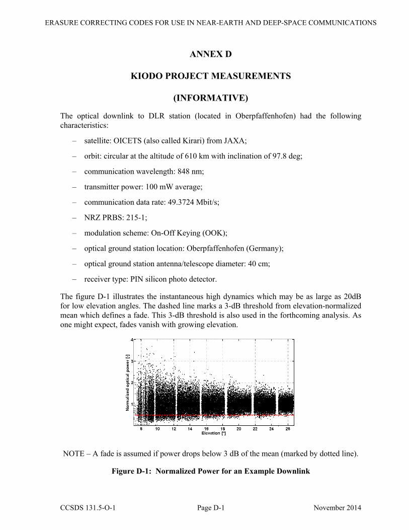
ERASURE CORRECTING CODES FOR USE IN NEAR-EARTH AND DEEP-SPACE COMMUNICATIONS
CCSDS 131.5-O-1 Page D-1 November 2014
ANNEX D
KIODO PROJECT MEASUREMENTS
(INFORMATIVE)
The optical downlink to DLR station (located in Oberpfaffenhofen) had the following characteristics:
– satellite: OICETS (also called Kirari) from JAXA;
– orbit: circular at the altitude of 610 km with inclination of 97.8 deg;
– communication wavelength: 848 nm;
– transmitter power: 100 mW average;
– communication data rate: 49.3724 Mbit/s;
– NRZ PRBS: 215-1;
– modulation scheme: On-Off Keying (OOK);
– optical ground station location: Oberpfaffenhofen (Germany);
– optical ground station antenna/telescope diameter: 40 cm;
– receiver type: PIN silicon photo detector.
The figure D-1 illustrates the instantaneous high dynamics which may be as large as 20dB for low elevation angles. The dashed line marks a 3-dB threshold from elevation-normalized mean which defines a fade. This 3-dB threshold is also used in the forthcoming analysis. As one might expect, fades vanish with growing elevation.
NOTE – A fade is assumed if power drops below 3 dB of the mean (marked by dotted line).
Figure D-1: Normalized Power for an Example Downlink
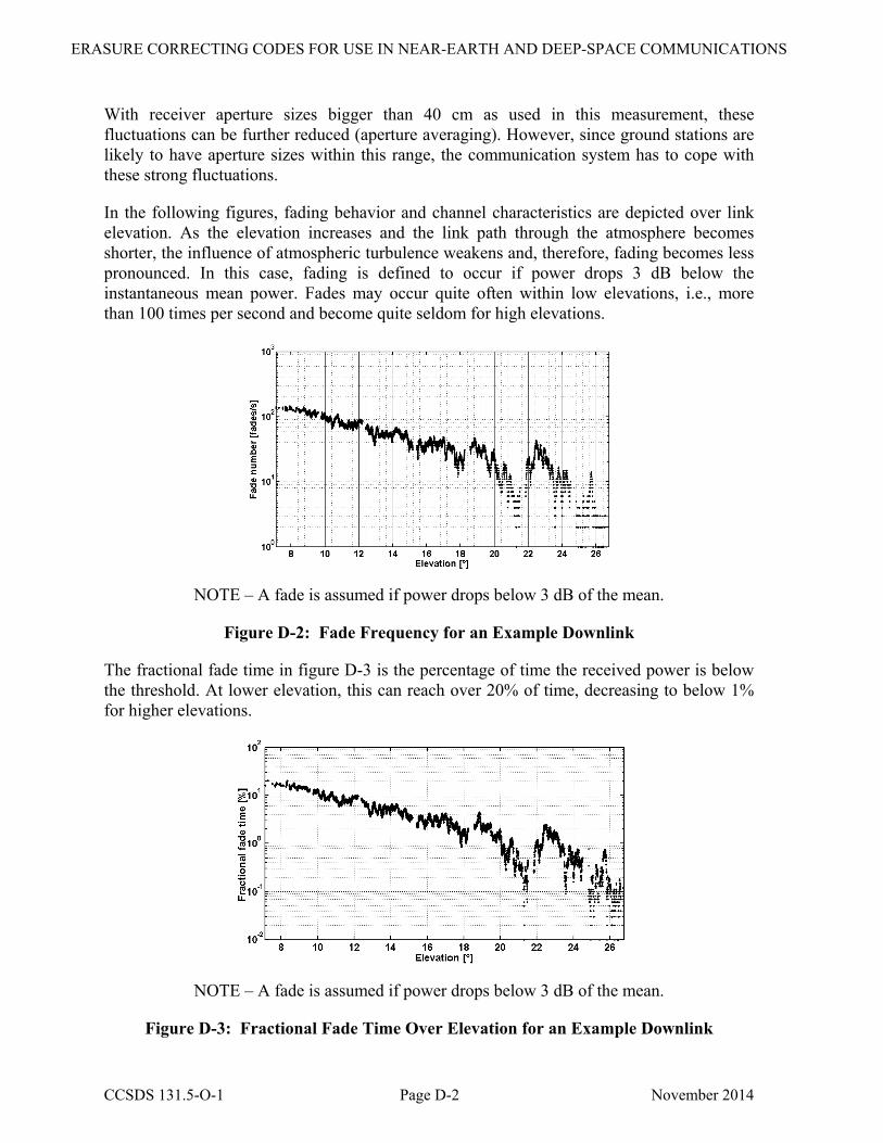
ERASURE CORRECTING CODES FOR USE IN NEAR-EARTH AND DEEP-SPACE COMMUNICATIONS
CCSDS 131.5-O-1 Page D-2 November 2014
With receiver aperture sizes bigger than 40 cm as used in this measurement, these fluctuations can be further reduced (aperture averaging). However, since ground stations are likely to have aperture sizes within this range, the communication system has to cope with these strong fluctuations.
In the following figures, fading behavior and channel characteristics are depicted over link elevation. As the elevation increases and the link path through the atmosphere becomes shorter, the influence of atmospheric turbulence weakens and, therefore, fading becomes less pronounced. In this case, fading is defined to occur if power drops 3 dB below the instantaneous mean power. Fades may occur quite often within low elevations, i.e., more than 100 times per second and become quite seldom for high elevations.
NOTE – A fade is assumed if power drops below 3 dB of the mean.
Figure D-2: Fade Frequency for an Example Downlink
The fractional fade time in figure D-3 is the percentage of time the received power is below the threshold. At lower elevation, this can reach over 20% of time, decreasing to below 1% for higher elevations.
NOTE – A fade is assumed if power drops below 3 dB of the mean.
Figure D-3: Fractional Fade Time Over Elevation for an Example Downlink

ERASURE CORRECTING CODES FOR USE IN NEAR-EARTH AND DEEP-SPACE COMMUNICATIONS
CCSDS 131.5-O-1 Page D-3 November 2014
The mean fade duration is important to estimate the number of data packets within a fade and is depicted in figure D-4. Depending on link elevation, the mean fade time lies between 0.2 ms and 1.6 ms.
NOTE – A fade is assumed if power drops below 3 dB of the mean.
Figure D-4: Mean Fade Time Over Elevation for an Example Downlink
The mean fade time has the same order of magnitude as the received power Auto-Correlation Time (ACT) as illustrated in figure D-5. In this case, the correlation time is defined as the 3-dB roll-off point in the concerned normalized auto-covariance function. Therefore it is the function’s half width at half maximum. However, the qualitative behavior of the ACT is different to those of the mean fade time. Whereas the later decreases monotonically, the ACT first increases up to a certain maximum and then decreases. The explanation is in the contraposition of two different phenomena. The first consists in the fact that turbulence is stronger with longer link paths and therefore the correlation time becomes shorter. The second is due to the slew rate of the satellite, which is quite small at low elevation angles and relatively large at high elevations. These two effects work against each other whereas during link time, the first dominates at low elevations and the second at higher.
Figure D-5: Fifty Percent Atmospheric Correlation Time Over Elevation for an Example Downlink

ERASURE CORRECTING CODES FOR USE IN NEAR-EARTH AND DEEP-SPACE COMMUNICATIONS
CCSDS 131.5-O-1 Page D-4 November 2014
These measurements were performed at wavelength of 847 nm; in case they have to be translated to other wavelengths the use of appropriate models is necessary. In reference [D1], the intensity correlation width is found to behave approximately proportionally to wavelength in the case of weak turbulence, i.e., link elevations over 10°. Furthermore, Taylor’s frozen turbulence theory, which gives the possibility to relate spatial to temporal statistics, can be applied. If those models are assumed to be valid, the correlation time is found to scale linearly with wavelength. Hence, the time dimensions in figure D-5 can be converted to other wavelengths. For instance, the correlation time being between 0.65 ms and 1.4 ms for 847 nm could lie in the range 1.2-2.6 ms for 1550 nm.

ERASURE CORRECTING CODES FOR USE IN NEAR-EARTH AND DEEP-SPACE COMMUNICATIONS
CCSDS 131.5-O-1 Page E-1 November 2014
ANNEX E
PERFORMANCE ANALYSIS
(INFORMATIVE)
E1 ONLINE CODE DESIGN
A rate ½ inner IRA LDPC code with a node oriented VN degree distribution is considered for ,i uH , 3 4 5 6 7 8 9 10
1( ) 0.543 0.102 0.008 0.020 0.008 0.008 0.047 0.266x x x x x x x x xΦ = + + + + + + + , which has been obtained by using the code design techniques of reference [G13]. The configuration 512in n= = is chosen along with an outer random code with parameters (256,246) . Based on the flexible construction technique described in 3.2, the parity-check matrix of the concatenated scheme is constructed with parameters (512, 246). By puncturing the parity symbols of the inner code (i.e., symbols associated with the columns of the double diagonal matrix ,i pH ) two other codes with parameters (379, 246) and (314, 246), respectively, are obtained. No particular optimization of the puncturing pattern has been performed. The CER performance of the three different codes on the BEC is depicted in figure E-1. It can be observed that in all cases the codes nearly coincide with the Berlekamp bound, while a merely minimal gap to the Singleton bound is visible. This is remarkable, since no girth optimization or optimization of the puncturing patterns has been performed.
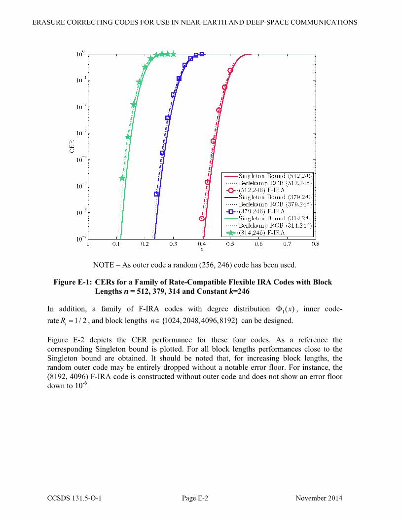
ERASURE CORRECTING CODES FOR USE IN NEAR-EARTH AND DEEP-SPACE COMMUNICATIONS
CCSDS 131.5-O-1 Page E-2 November 2014
NOTE – As outer code a random (256, 246) code has been used.
Figure E-1: CERs for a Family of Rate-Compatible Flexible IRA Codes with Block Lengths n = 512, 379, 314 and Constant k=246
In addition, a family of F-IRA codes with degree distribution 1( )xΦ , inner code-rate 1/ 2iR = , and block lengths {1024,2048,4096,8192}n∈ can be designed.
Figure E-2 depicts the CER performance for these four codes. As a reference the corresponding Singleton bound is plotted. For all block lengths performances close to the Singleton bound are obtained. It should be noted that, for increasing block lengths, the random outer code may be entirely dropped without a notable error floor. For instance, the (8192, 4096) F-IRA code is constructed without outer code and does not show an error floor down to 10-6.

ERASURE CORRECTING CODES FOR USE IN NEAR-EARTH AND DEEP-SPACE COMMUNICATIONS
CCSDS 131.5-O-1 Page E-3 November 2014
NOTE – Different outer codes have been used.
Figure E-2: CERs for a Family of Flexible IRA Codes with Block Lengths n = {1024, 2048, 4096, 8192} and Inner Code-Rate Ri=1/2
E2 AD-HOC CODE DESIGN
The CER performance of the 9 different codes from table 4-1 on the uncorrelated BEC is depicted in figures E-3, E-4, and E-5. All results were obtained by applying ML-P decoding as described in 2.2.4. In all cases performances close to the Singleton bounds are achieved.
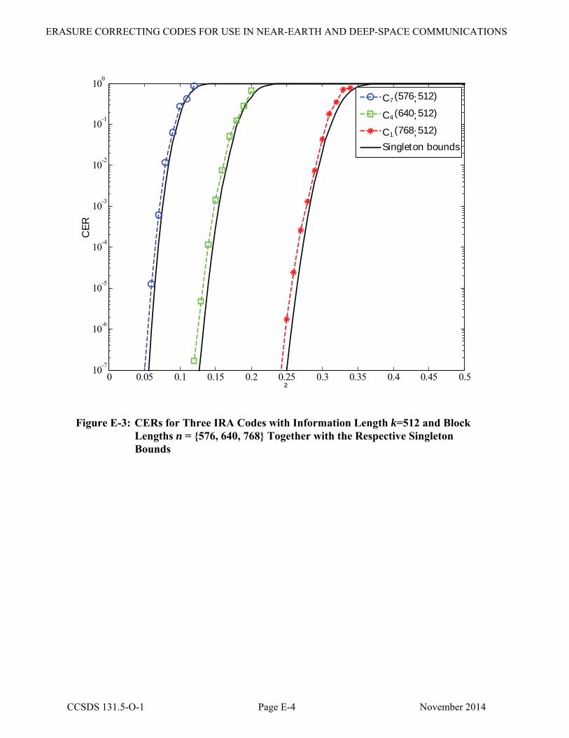
ERASURE CORRECTING CODES FOR USE IN NEAR-EARTH AND DEEP-SPACE COMMUNICATIONS
CCSDS 131.5-O-1 Page E-4 November 2014
0 0.05 0.1 0.15 0.2 0.25 0.3 0.35 0.4 0.45 0.510-7
10-6
10-5
10-4
10-3
10-2
10-1
100
²
CER
C7 (576;512)
C4(640;512)
C1(768;512)Singleton bounds
Figure E-3: CERs for Three IRA Codes with Information Length k=512 and Block Lengths n = {576, 640, 768} Together with the Respective Singleton Bounds

ERASURE CORRECTING CODES FOR USE IN NEAR-EARTH AND DEEP-SPACE COMMUNICATIONS
CCSDS 131.5-O-1 Page E-5 November 2014
0 0.05 0.1 0.15 0.2 0.25 0.3 0.35 0.4 0.45 0.510-7
10-6
10-5
10-4
10-3
10-2
10-1
100
²
CER
C8 (2304;2048)
C5(2560;2048)
C2(3072;2048)Singleton bounds
Figure E-4: CERs for Three IRA Codes with Information Length k=2048 and Block Lengths n = {2304, 2560, 3072} Together with the Respective Singleton Bounds

ERASURE CORRECTING CODES FOR USE IN NEAR-EARTH AND DEEP-SPACE COMMUNICATIONS
CCSDS 131.5-O-1 Page E-6 November 2014
0 0.05 0.1 0.15 0.2 0.25 0.3 0.35 0.4 0.45 0.510-7
10-6
10-5
10-4
10-3
10-2
10-1
100
²
CER
C9 (18432;16384)
C6(20480;16384)
C3(24576;16384)Singleton bounds
Figure E-5: CERs for Three IRA Codes with Information Length k=16384 and Block Lengths n = {18432, 20480, 24576} Together with the Respective Singleton Bounds
ERASURE CORRECTING CODES FOR USE IN NEAR-EARTH AND DEEP-SPACE COMMUNICATIONS
CCSDS 131.5-O-1 Page F-1 November 2014
ANNEX F
ABBREVIATIONS AND ACRONYMS
(INFORMATIVE)
ACT auto-correlation time
ADU application data unit
AMS Asynchronous Message Service
AOS Advanced Orbiting Systems
APID application process identifier
ARQ automatic repeat queuing
AWGN additive white Gaussian noise
BEC binary erasure channel
BP Bundle Protocol
BPA bundle protocol agent
BSP Bundle Security Protocol
CER codeword error rate
CFDP CCSDS File Delivery Protocol
CLA convergence layer adapter
CN check node
CP coding parameters
CPU central processing unit
CRC cyclic redundancy check
DRU data redundancy unit
DSN Deep Space Network
DTN Delay Tolerant Network
DVB-SH Digital Video Broadcasting—Satellite Services to Handhelds
EC erasure coding
ECDU erasure coding data unit

ERASURE CORRECTING CODES FOR USE IN NEAR-EARTH AND DEEP-SPACE COMMUNICATIONS
CCSDS 131.5-O-1 Page F-2 November 2014
EESS Earth Exploration Satellite Service
ESB extension security block
F- IRA flexible IRA
FEC forward error correction
FER frame error rate
F-IRA flexible IRA
GeIRA generalized IRA
IETF Internet Engineering Task Force
ION Interplanetary Overlay Network
IP Internet Protocol
IRA irregular-repeat-accumulate
IRTF Internet Task Research Task Force
KIODO Kirari optical satellite downlinks to Oberpfaffenhofen
LCG linear congruential generator
LDPC low-density parity-check
LEC long erasure code
LS long erasure code symbol
LSC LS counter
LTP Licklider Transmission Protocol
LW long erasure code word
LWC LW counter
MCW maximum column weight
MDS maximum distance separable
ML maximum-likelihood
ML-P maximum-likelihood pivoting
MSB most significant bit
NRZ non-return-to-zero
OICETS Optical Inter-Orbit Communications Engineering Test Satellite

ERASURE CORRECTING CODES FOR USE IN NEAR-EARTH AND DEEP-SPACE COMMUNICATIONS
CCSDS 131.5-O-1 Page F-3 November 2014
OOK on-off keying
OSI Open Systems Interconnection
PDU protocol-data-unit
PEC packet erasure channel
PIB payload integrity block
PICS protocol implementation conformance statement
PRBS pseudorandom binary sequence
RF radio frequency
RFC Request for Comment
RFI radio frequency interference
RL requirements list
RS Reed-Solomon
SAP service-access-point
SDLP space data link protocol
SDNV self-delimiting numeric values
SDU service-data-unit
SNR signal-to-noise ratio
SPP Space Packet Protocol
TBD to be determined
TBR to be required
TC telecommand
TLV type length value
TM telemetry
UDP User Datagram Protocol
VN variable node

ERASURE CORRECTING CODES FOR USE IN NEAR-EARTH AND DEEP-SPACE COMMUNICATIONS
CCSDS 131.5-O-1 Page G-1 November 2014
ANNEX G
INFORMATIVE REFERENCES
(INFORMATIVE)
[G1] K. Scott and S. Burleigh. Bundle Protocol Specification. RFC 5050. Reston, Virginia: ISOC, November 2007.
[G2] M. Ramadas, S. Burleigh, and S. Farrell. Licklider Transmission Protocol—Specification. RFC 5326. Reston, Virginia: ISOC, September 2008.
[G3] Space Data Link Protocols—Summary of Concept and Rationale. Issue 2. Report Concerning Space Data System Standards (Green Book), CCSDS 130.2-G-2. Washington, D.C.: CCSDS, November 2012.
[G4] Larry C. Andrews, Ronald L. Phillips, and Cynthia Young Hopen. “Scintillation Model for a Satellite Communication Link at Large Zenith Angles.” Optical Engineering 39, no. 12 (Dec. 1, 2000): 3272–3280.
[G5] T. De Cola, et al. “Reliability Options for Data Communications in the Future Deep-Space Missions.” Proceedings of the IEEE 99, no. 11 (Nov. 2011): 2056–2074.
[G6] E. Paolini, et al. “Recovering from Packet Losses in CCSDS Links.” In Proceedings of the 4th Advanced Satellite Mobile Systems Conference (26–28 Aug. 2008, Bologna, Italy). 283–288. New York: IEEE, 2008.
[G7] R. G. Gallager. Low Density Parity Check Codes. Monograph. Cambridge, Massachusetts: MIT Press, 1963.
[G8] William Ryan and Shu Lin. Channel Codes: Classical and Modern. New York: Cambridge UP, 2009.
[G9] Richard C. Singleton. “Maximum Distance q-nary Codes.” IEEE Transactions on Information Theory 10, no. 2 (Apr. 1964): 116–118.
[G10] E. Berlekamp. “The Technology of Error-Correcting Codes.” Proceedings of the IEEE 68, no. 5 (May 1980): 564–593.
[G11] H. Jin, A. Khandekar, and R. McEliece. “Irregular Repeat-Accumulate Codes.” In Proceedings of the 2nd International Symposium on Turbo Codes and Related Topics (Sep. 2000, Brest, France). 1–8.
[G12] G. Liva, P. Pulini, and M. Chiani. “On-Line Construction of Irregular Repeat Accumulate Codes for Packet Erasure Channels.” IEEE Transactions on Wireless Communications 12, no. 2 (Feb. 2013): 680–689.

ERASURE CORRECTING CODES FOR USE IN NEAR-EARTH AND DEEP-SPACE COMMUNICATIONS
CCSDS 131.5-O-1 Page G-2 November 2014
[G13] E. Paolini, et al. “Maximum Likelihood Erasure Decoding of LDPC Codes: Pivoting Algorithms and Code Design.” IEEE Transactions on Communications 60, no. 11 (Nov. 2012 ): 3209–3220.
[G14] Overview of Space Communications Protocols. Issue 3. Report Concerning Space Data System Standards (Green Book), CCSDS 130.0-G-3. Washington, D.C.: CCSDS, July 2014.
[G15] Rationale, Scenarios, and Requirements for DTN in Space. Issue 1. Report Concerning Space Data System Standards (Green Book), CCSDS 734.0-G-1. Washington, D.C.: CCSDS, August 2010.
[G16] Organization and Processes for the Consultative Committee for Space Data Systems. Issue 4. CCSDS Record (Yellow Book), CCSDS A02.1-Y-4. Washington, D.C.: CCSDS, April 2014.
[G17] S. Farrell, M. Ramadas, and S. Burleigh. Licklider Transmission Protocol—Security Extensions. RFC 5327. Reston, Virginia: ISOC, September 2008.
[G18] CCSDS File Delivery Protocol (CFDP). Issue 4. Recommendation for Space Data System Standards (Blue Book), CCSDS 727.0-B-4. Washington, D.C.: CCSDS, January 2007.
[G19] T. de Cola and Mario Marchese. “Reliable Data Delivery over Deep Space Networks: Benefits of Long Erasure Codes over ARQ Strategies.” IEEE Wireless Communications 17, no. 2 (2010): 57–65.
[G20] M. Chiani, G. Liva, and E. Paolini. “Long Erasure Correcting Codes: A New Appealing Chance for Space Applications Protocols?” Presented at CCSDS Coding and Synchronization Working Group meeting (May 2004, Montreal, Canada).
[G21] G. Liva, et al. “A Decoding Algorithm for LDPC Codes over Erasure Channels with Sporadic Errors.” In Proceedings of the 48th Annual Allerton Conference on Communication, Control, and Computing (Sept. 29 2010–Oct. 1 2010, Allerton, Illinois). 458–465. New York: IEEE, 2010.
[G22] G. Liva, E. Paolini, and M. Chiani. “Simple Reconfigurable Low-Density Parity-Check Codes.” IEEE Communications Letters 9, no. 3 (Mar. 2005): 258–260.