erasmus + iesres innovative european studies on renewable
TRANSCRIPT

Study of a Three-Phase Synchronous Generator With Claw Poles, by Finite Element Method Used in Automobiles
Erasmus + IESRES
Innovative European Studies on Renewable Energy Systems
Programme of Teaching/Learning Activity
08th – 12th ay 2017, Klaipėda, Lithuania
Phd. STOICA CONSTANTINUniversity of Pitesti
Romania

1.INTRODUCTION
1.1 Electricity production on board cars.
1.2 Increasing electricity consumption on board cars.
1.3 Choosing the electric generator in the used car.
1.4 Dual Power Supply Systems (14V-48V) or 48V Simple.
1. 5 Construction types of alternators.

1.1 Electricity production on board cars. The first three-phase synchronous generator generates electricity claw-
pole in 1891, flowing through the three-phase electric line from Lauffen to Frankfurt of Main in Germany.
Electricity generation in the car is done with a three-phase synchronous generator, equipped with a rectifier bridge, with the name alternator.
The need for electric power on board the car is set by: Consumption of electrical loads for a particular working regime Battery charging status.
The electrical generator used in the car is the claw-poles alternator with: advantage
Simple construction The single excitation coil.High reliability. Low cost price

Disadvantages: Low yield of (55-60)% determined by the high dispersion magnetic flux
High values for friction and ventilation Losses, when the rotor speed is 10.000 to 15.000 rpm
The car industry is making major changes harm will also have an effect on electric generators on the car because:
Increasing the number of electric motors installed on the car
Increase in Electric Power Consumed on board the car.
Today specialists involved in the production of electric generators are studying:
Improving the performance of existing electric generators
Better adaptation of different control strategies.

1.2 Increasing electricity consumption on board cars.
Increasing levels of comfort and safety on board, as well as pollution rules, lead to the emergence of new types of electric consumers such as:
Electric cooling
Variable distribution with electromagnetic actuated valves
Active suspension
Hybrid technology

The time evolution of the maximum consumption, determined by the loads installed on the vehicle Considering the working voltage of 14 V

1.3 Choosing the electric generator in the used car.
In choosing and using the alternator, the maximum power required for all consumers on the car, which can be:
• Permanent
• Intermittent
• Variables (battery)
• Day or night
• The rotor speed at which the rated voltage flows
• The training report
• The regulated voltage

Checking the correct selection is made by the alternator current characteristic I = f (n), represented for two unfavorable limit cycles:

1. Urban driving cycle with low travel speeds, and stops stationary driving (eg Urban Driving Cycle ECE 15)
2. Electric load cycle in the worst case (eg City Cycle During the winter with many consumers and speed reduced).

1.4 Dual Power Supply Systems (14V-48V) or 48V simple.In the case of cars with high power consumption on board, it was
decided to gradually shift from the supply voltage from 14 V to 48 V due to the advantages:
Lower circuit currents and reduced section conductors
Centralized distribution voltage
Low fuse fuses
Standardized power system: (5V-14V-48V)

1. 5 Construction types of alternators.
1.5.1 The claw poles alternator compact cooled with air biflux advantage
An increased efficiency due to the maximum engine speed higher training.
Reduced aerodynamic noise due to the use of small diameter ventilator.
Increased winding longevity

1.5.2 The alternator with poles apparently, cooled by water; P> 3kW.
advantages• Low interpolar dispersion flux
• Long axial length
disadvantages• Low maximum speeds
• Cooling with water
• More excitation coils
• Power relay connected to
• exterior

1.5.3 The alternator with glass rotor and non-magnetic ring, without ring collector, cooled by water
• advantage• The absence of air movement noise
• Full encapsulation and high sealing
• Possible use at high temperatures in the
engine compartment.
• Assembly in the engine block.
• disadvantages• Two air gap
• higher volume and weight

1.5.4 Alternator with excitation with permanent magnets
• advantages• Excitation winding replaced by permanent magnets
• Lack of rings and brushes
• Low cost price
• disadvantages• Requires converter to adjust voltage to U = 14V
• Mechanical requests due to vibrations
• Demagnetizing thermal applications

THE NUMERICAL MODEL INTEGRATION OF 3D USING THE FINITE ELEMENT METHOD FOR THE
CALCULATION OF THE MAGNETIC FIELD IN ALTERNATOR WITH CLAW POLES
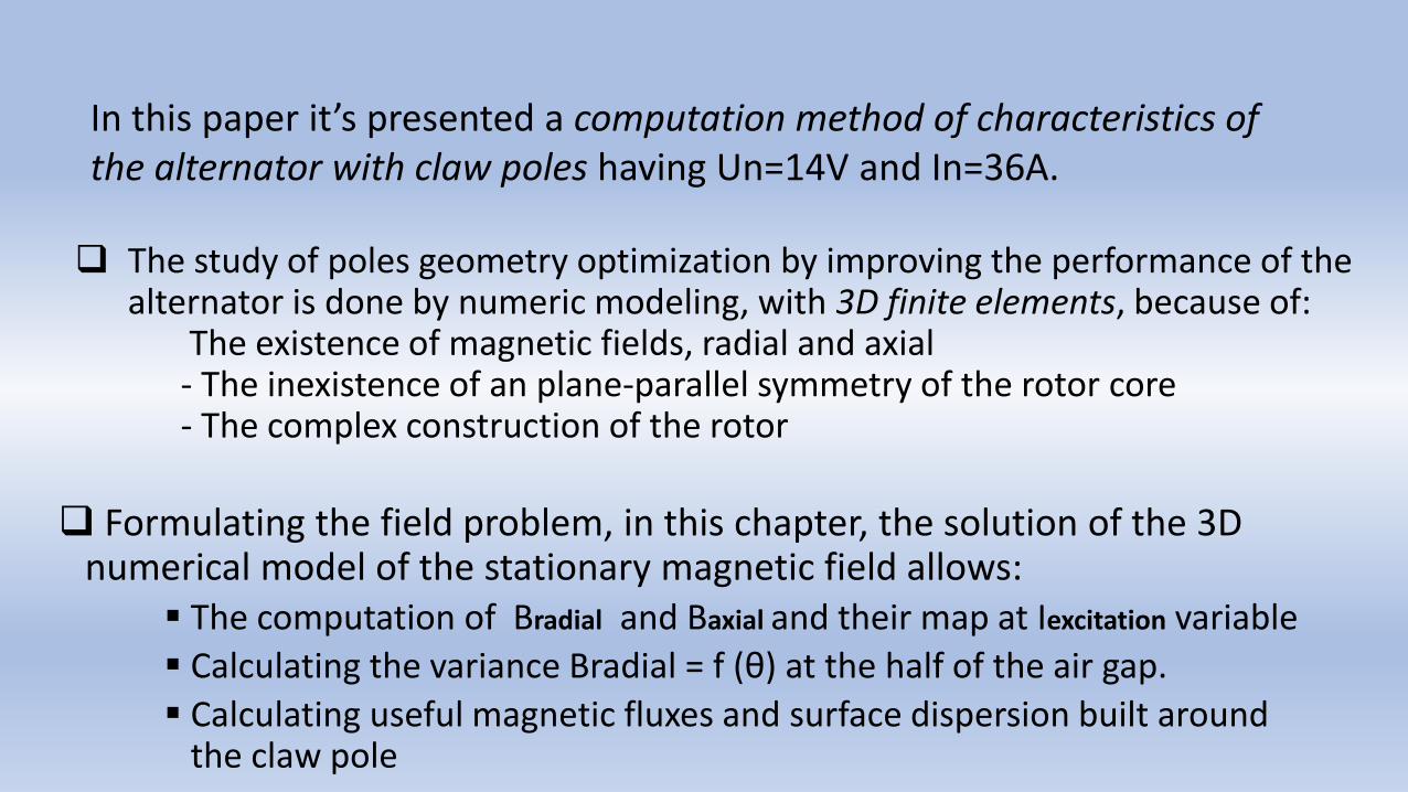
The study of poles geometry optimization by improving the performance of the alternator is done by numeric modeling, with 3D finite elements, because of:
The existence of magnetic fields, radial and axial - The inexistence of an plane-parallel symmetry of the rotor core- The complex construction of the rotor
Formulating the field problem, in this chapter, the solution of the 3D numerical model of the stationary magnetic field allows:
The computation of Bradial and Baxial and their map at Iexcitation variable
Calculating the variance Bradial = f (θ) at the half of the air gap.
Calculating useful magnetic fluxes and surface dispersion built around the claw pole
In this paper it’s presented a computation method of characteristics of the alternator with claw poles having Un=14V and In=36A.

Choosing the computing field and the coordinate system is made considering:- Plans of constructive symmetry common to the two magnetic cores ( stator and rotor)- The conditions of periodicity on the frontiers
The chosen computing field corresponds to one pair of poles, being the sixth part of the magnetic volume of the alternator
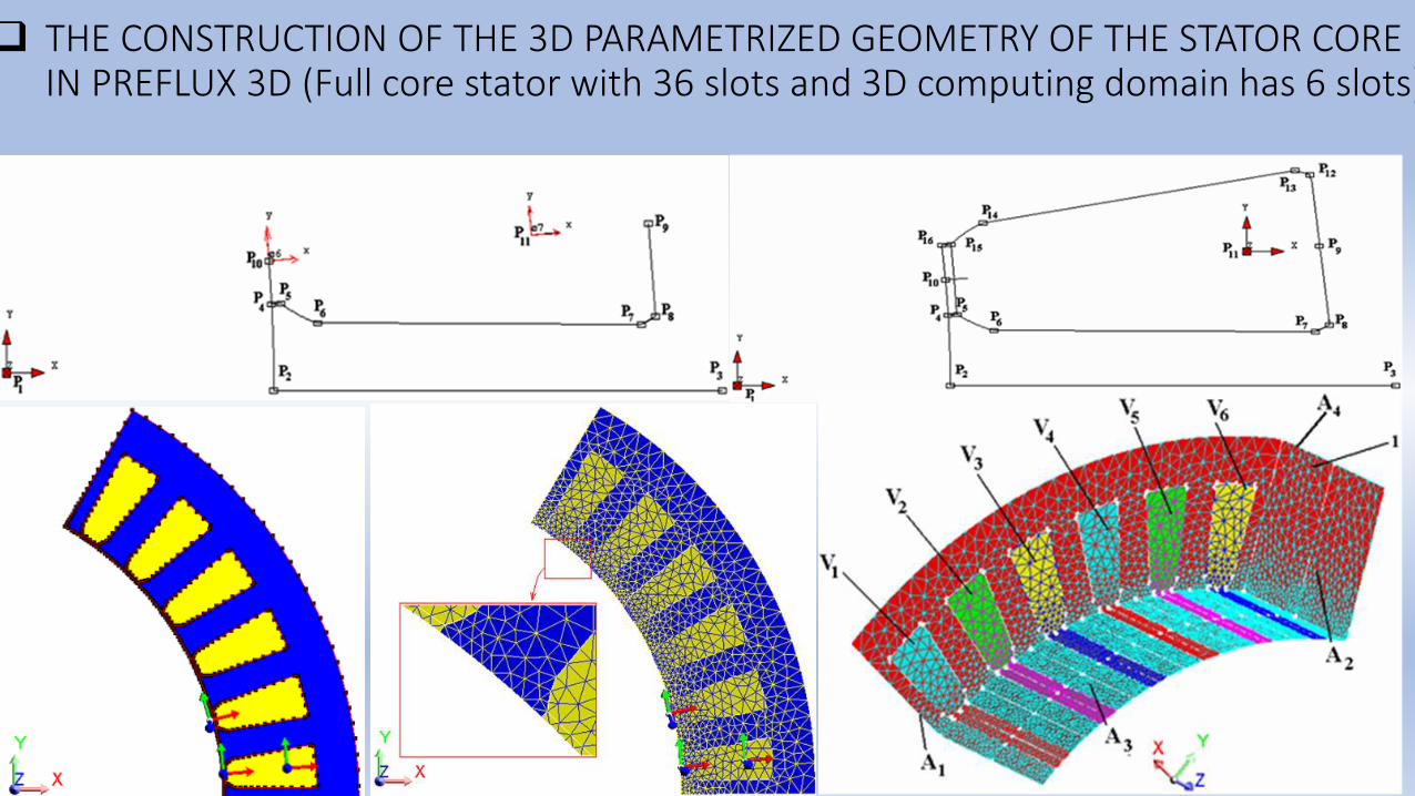
THE CONSTRUCTION OF THE 3D PARAMETRIZED GEOMETRY OF THE STATOR CORE IN PREFLUX 3D (Full core stator with 36 slots and 3D computing domain has 6 slots)

THE CONSTRUCTION OF THE 3D PARAMETRIZED GEOMETRY OF THE ROTOR CORE IN CATIA V5 R 17 (Full core rotor with 12-poles and the 3D computing domain has a pair of poles

THE DEFINITION OF THE 3D PARAMETERIZED DOMAIN OF CALCULATION OF THE ALTERNATOR (STATOR AND ROTOR) AND FINITE ELEMENT NETWORK
54 368 nodes, 339 689 first order volume elements 53,93% of excellent quality36,59% of good quality8,68% of satisfactory quality0,79% of low quality

Magnetic properties of the cores
MATHEMATIC MODEL OF THE STATIONARY MAGNETIC REGIM
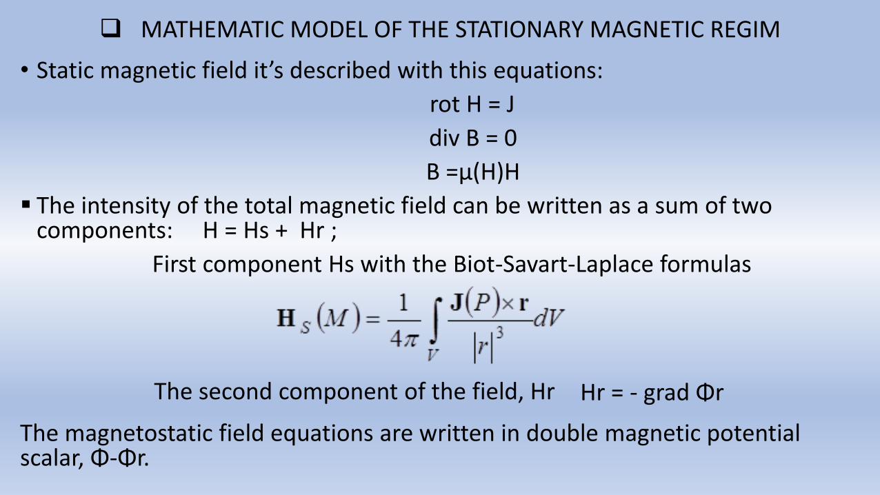
• Static magnetic field it’s described with this equations:
rot H = J
div B = 0
B =µ(H)H
The intensity of the total magnetic field can be written as a sum of two components: H = Hs + Hr ;
First component Hs with the Biot-Savart-Laplace formulas
The magnetostatic field equations are written in double magnetic potential scalar, Φ-Φr.
The second component of the field, Hr Hr = - grad Φr

THE RESULTS OF NUMERICAL CALCULATION 3D IN THE STATIONARY MAGNETIC REGIM ( Magnetic radial induction )

The arcing circle for the purpose of calculating Br(θ),the Iexcitation = 2A.Evolution radial component of the magnetic induction depending on the angle θ, considering R and z = constant
CONCLUSIONS
• Car claw pole alternators have a standard number of 12 poles to all producers in the world.
The 3D numeric model allows
• Improve performance are determined by the geometry optimization claw pole.
• Computation waveform induced electromotive force was necessary to resolve a number of problems for 120 successive positions of the rotor relative to the stator in the range of two polar steps.
• Differences between induced electromotive voltage calculated by FEM and the measured geometric approximations can be explained by poles shape but also by the magnetization characteristics of the materials used.