equivalent load concept
TRANSCRIPT

The slope of the cable at each end is 0 = 3eo/L, and the forces a.pplied to each endof the beam consist of a horizontal component P and a vertical component PO(assuming small angles as before). At each end, the horizontal ~entroidal forcecausing axial compression in the concrete is thus P and the vertical downwardforce at each end is PO= 3Peo/L (Figs 6.9 (b) and (cl).
At a kink the change in direction of the cable requires a force F to be applied tothe cable by the concrete (Fig 6.9 (d», where F = PO, i.e. F = 3PeJL. Strictly, Factsat an inclination of Oj2 to the vertical, but this is very close to being vertical. Thereactive force exerted by the cable on the concrete is thus F = 3Pe/L and isassumed to be vertical, as shown in Fig 6.9 (e).
At each third point, there is thus an upward equivalent load F acting on the concrete. The two forces F and the forces applied at the ends of the beam are theequivalent loads. Since the cable, considered as a free body, must be in equilib-
t 3PecJLt3PecJLFigure6.9 Equivalentloads-draped cable
~ 3PecJL 3PecJL tIe) .e..._F---------------------~ .;»
(e)(d)(e)(b)
F
J_
I.) E-- -- -- -- -:10- -- -- -- --jI: L/3 ·1 L I. L/3 :1
~L~IL
6.3.2 DrapedcablesPretensioned beams usually have tendons that are either straight throughout thelength of the beam, or draped, i.e. consisting of straight segments connected bykinks. A kink in the tendon produces a concentrated force on the concrete.
The beam shown in Fig 6.9 is prestressed by a draped cable which has kinks atthe third points of the span. The eccentricity of the cable is zero at each end, ande in the middle third region. The cable thus exerts forces on the concrete beam atthe ends and at the third points of the span where the two kinks occur, To simplify the discussion, we assume that the cable force is constant throughout thelength of the beam.
Chapter 6 Fie xu rei n be a m s wit h pre s t res s 123
If the anchorage is located at an eccentricity e away from the centroidal axis, theequivalent load may be shown in any of the ways indicated in Fig 6.8 (d), (e) or(f). It is usually convenient to use the equivalent force system at the centroidalaxis as shown in Fig 6.8 (f).
(f) equivalent systemat centroidral axis
(e)components(d)equivalent load -eccentricanchorage
Figure6.8 Equivalentloadsat anchorage
._I't:..._u:-\_-~--
(c)for small angles(b) components(a)equivalent load
rotEP- .--:_tt=ine- --------Peose
6.3.1 Forcesat anchoragesAt its anchorage a prestressing cable exerts on the concrete an equivalent loadwhose magnitude is that of the prestressing force and whose direction is that ofthe cable at the anchorage. If the anchorage is located at the centroid of the beamcross-section, the equivalent load may be shown either directly as in Fig 6.8 (a) orusing horizontal and vertical components as in Fig 6.8 (b). However it is normalto use the small angle approximations sinO = (J, cose = 1, and express the components as shown in Fig 6.8 (c).
In the equivalent load method, all the forces exerted on the concrete member bythe prestressing tendon are determined and used to determine the effects of prestress on the beam. These forces are termed equivalent loads and occur at theanchorages and wherever the cable changes direction. We consider the commoncases in turn ..
Equation 6.1can be used to determine the stresses due to prestress in any desiredsection in a statically determinate beam. An alternative procedure, called theequivalent load method, can be used to evaluate the effects of prestress. Thisapproach provides the basis for a design technique called [ami. haumcin..g., which ispar~sula.rJy tl,~ful J!l. th£,.Rreliminary_<iep'jgD~QLE.~~§.~d c~ncrete structuresand will be used frequently in later: cha:eters of this book. The equivalent load--_. ~-,,~-"»~~~-"~~~-"~,.,~.-_.__.----......~-.-.~".•,-. ."'-'~~concept provides an insight into the effect of prestress on both statically determi-nate and statically indeterminate beams. However, in introducing the concepthere we concentrate attention on simply supported beams.
Equivalent load concept6.3
122 Beams in bending Part 2

(6.14)
The slope at the left end is thus 4hiL,and at the other end the slope is -4hfL. The curvature, or rate of changeof slope of the cable,isobtained by a second differentiation:
(6.13)tJJL = e = 4~(1- 2~)dx L L
The slope of the cable is obtained by differentiation:
(6.12)
The parabola shown in Figure 6.12 has length L and at its mid-length has an offset, relative to the line joining its ends, ofh.This offset is referred to as the sag ofthe parabola. ______...,.--,,-"--"-:~ . -_,--_.,.,....-IThe general equation of a parabola is:y = ax2 + bx + c. For the symmetrical parabola shown in Fig 6.12, we can readily determine the values of the constants a, band c from the boundary conditions (x = 0, y = 0; x = L/2, Y = h; x = L, Y = 0). Theequation of the parabola becomes:
Figure 6.12 Paraboliccableprofile
L
Post-tensioning cables usually have parabolic profiles. Because the paraboliccablehas constant curvature it exerts a uniformly distributed equivalent load onthe concrete.
6.3.3.1 Paraboliccables
Wp = PI( (6.11)
where x is the curvature (change in slope per unit length) of the cable at the pointconsidered; wp is the force per unit length exerted by the concrete on the cable,which is of course equal and opposite to the force the cable exerts on the concrete.It acts radially, but for small angles can be considered to act vertically with negligible error.
The force per unit length, wP' is therefore:
L1F = 2PSinL12f} = PL18 (for small angles)
Chapter 6 Flexure in beams with prestress 125
Figure 6.11 Segmentof curvedprestressingcable
6.3.3 Cableswith curved profilesMost post-tensioned beams have tendons with curved profiles. Figure 6.11 showsa free body diagram of a small segment of a curved cable which carries prestressing forceP. Over the length Lix, the change in slope of the cable is .£le.
Equilibrium requires that the cable must be acted upon by radial forces with aresultant L1F as shown. From the triangle of forces in the figure, it can readily bededuced that the magnitude of the resultant, for cable length Lix, is:
4 pre! + e2)L
Figure 6.10 Equivalentloads-draped cablewith eccentricanchorages
(6.10)
rium, it follows that the full set of equivalent loads acting on the concrete member, shown in Fig 6.9 (f), must be self-equilibrating.
The concretemember can now be analysed for the effectsof the equivalent loads.From Fig 6.9 (f), these loads cause a constant moment in the middle third regionof the span equal to M = -(3Peo/ L) x (L/3) = -Pe.; This is of course the samemoment which is obtained by considering the prestressing force in the sectionand its eccentricity,i.e. hlp = Pe.;
Figure 6.10 shows a further example of a beam in which the cable has a singlekink at mid-span, with the end anchorages located eccentrically above the centroid by an amount el' The mid-span eccentricity is e2' The equivalent load atmid-span is 4P(el + e~fL and downward forces of 2P(el+ e~fL act at each end. Atthe ends the applied moment is + Pel' The resultant moment due to prestress atmid-span is:
124 Beams in bending Part 2

Cnaptz-r fj Flexure in beams with prestress 127
In Fig 6.13, the prestressing tendon has end eccentricitieseo above the centroidalaxis at each end of the beam, and downward eccentricity el at mid-span. For usein Eq 6.15,sag h = eo+ el' The equivalent loads at the ends of the beam consist offorce P acting at the cable position and in the cable direction, i.e. at slope 4h/L tothe horizontal. This is resolved into horizontal component P and vertical component pe = 4Ph/L, together with end moment Pel acting at the centroid, as shownin Fig 6.13.
Iilij'11i!\,! I'
!JI!:I:I 1·'
II i;!i
,iI)11! i< I
Figure 6.13 Equivalentloads-parabolic cable
i .·1: '
The negative sign indicates that w acts upwards when the sag h is downwards.The equivalent load for any parabolic cable segment can be obtained fromEq 6.15,provided that the mid-span sag h is measured from the straight line joining the two ends of the segment.
(6.15)W = PI( = _(8Ph)P L2
It follows that if a prestressing cable has the parabolic profile shown in Fig 6.12,and carries a prestressing force P, the equivalent load exerted by the cable on theconcrete is a uniformly distributed load:
126 Beams in bending Part 2

6.4
One of the most important uses of prestress in the design of concrete structures isto improve structural behaviour under service load conditions. The concept ofload balancing, which is a simple development from the equivalent load methodof analysis discussed in the previous section, provides a useful means for determining the appropriate prestress details for many design situations.
Load balancing
(c) stressdistributions
Figure 6.18 Prestressed beam with varying centroida! axis
V--rJ------O---------------17--i~------- -------- ,
-- BB CC ~ :AA DD
(b) variation in eccentricity
x..L(a)beamwith varying centroidal axis
A
straightcable
A B E C F D G
----- 1_______--- ------
7.~~ Ic 0
7.hB
Inthe case of a member with a non-straight centroidal axis, care must be taken toevaluate correctly the eccentricity of the longitudinal force due to prestress. InFig 6.18 (a) the depth of the centroidal axis varies linearly in region AE, as theresult of the haunch; it is constant in the constant-section region EF, but makes ajump at section F and then remains constant in region FG. The cable is straightand therefore the only equivalent loads are horizontal forces at the ends of thebeam. However, the eccentricity is variable (Fig 6.18 (b)); typical stress distributions are shown in Fig 6.18 (c).
(6.18)
the position of the cable and the straight line joining BC, at the cantilever midspan point. It is however simpler to use the parabola obtained by including themirror image of segment BC beyond C (shown dashed in the figure), so that:
Cnanter 6 Flexure in beams with prestress 129
For the.cantilever span BC, the equivalent load may be obtained by using Eq 6.15directly, i.e. wp = 8Ph/a2, provided that sag h is measured as the distance between
(6.17)4h eB8A = --- radL L
::. ~
The end slope of the parabola may be calculated in two steps. The angle betweenthe parabola at A and the chord AB is 4h/L. Chord AB has slope eB/L. The slope ofthe parabola at A, used in calculating the vertical component of the equivalentload at the anchorage, is therefore:
(6.16)8PhW = -- =P L2
The equivalent load for span AB is:
Figure 6.17 Equivalent loads, beam with cantilever
~~L~~L:::~i=~ r1 L/2 I. L/2 .1. a ,I
Figure 6.17 shows a post-tensioned beam with span L and cantilever span a. Inspan AB, the cable is parabolic with zero eccentricity at A, eccentricity eM belowthe axis at the mid-span point M, and eccentricity eB above the axis at support B.In the cantilever span, the cable is parabolic and has zero eccentricity and zeroslope at end C.
1 :
128 Be am sin ben din 9 Part 2
'I" '!.f '.;. l '.

(b) cable shown as treebody
i Figure 6.19 Load balancing
Consider for example the beam of Example 6.2 when subjected to a distributedapplied load, including self-weight, of 24kN/m. It can be seen in Fig 6.19(a) thatat every section along the beam the bending moment and shear force producedby the external load are equal and opposite to those produced by the equivalentloads due to prestress. The concrete is thus in a state of uniform axial compression under the prestressing forceP = 1200 kN. Themagnitude of the compressivestress is (1'" PIAg = 3.75MPa. The beam undergoes only axial contraction: there isno bending moment and no deflection.
In the balanced load condition, the cable may be thought of as carrying (or balancing) the external load, while the concrete, in axial compression, provides thehorizontal reactive forces required at each end of the cable (Fig6.19(bl).
By choosing an appropriate design load to balance, the. designer can determinethe cable force and cable profile to be used in a flexural member. The balancedload may be the self-weight of the structure, the self-weight plus the permanentload, or even the total permanent load plus a proportion of the live load. The serviceability requirements for design are automatically satisfied for the balancedload condition since there is no cracking and no deflection.After the prestressingdetails have been determined by load. balancing, serviceability conditions attransfer and under full working load must be checked. .
In the discussion of equivalent loads up to this point, we have made the simplifying, but inaccurate, assumption that the prestressing force P is constant throughout the length of the beam. In reality,as discussed in detail in Chapter 10, frictionlosses occur throughout the length of a curved cable, so that P decreases with distance from the anchorage.
1200kN I I 1200kNT I 24kN/m l
~ ~-t~..t_...t._-1+____:tL-.!--~---t _._
120kN 120kN
(a) two equal and opposite load systems acting on concrete
24kN/m~ ~ t t ~ + ~ + t t
1200kN~
1 24~N/mt 1~~i~tt120 kN
t120 kNt,20 kN
The term load balancing refers to the introduction of a system of prestressing into amember such that the internal equivalent loads are equal and opposite to asystem of externally applied design loads. The external load system is then saidto be 'balanced' by the prestress.
130 Beams in bending Part 2

The designer also needs to consider time-dependent prestress losses, which arediscussed in Chapter 10. Since the long-term state of the beam is normally ofmost interest, load balancing design calculations are based on the effective prestress, after all prestress losses have occurred. However, calculations of conditions immediately after transfer must of course be based on the initial prestress.These considerations are illustrated in the following example. I ~); La SSe S
j ~.Y\._Q
~
It is common to use the magnitude of P at mid-span in load balancing calculations, e.g. in Eq 6.15.This is normally adequate for practical design, and shouldensure that the deflection at the balanced load is very small- although it may notbe zero. If greater accuracy is required, a segmental analysis may be undertaken.
Chaoter 6 Flexure in beams with prestress 131
ifIi
1!'I'
Iiil
j ~I!Ii.~:I!
i:1:1
133
Figure 6.21 Strains in section with prestress
.18 D F Q
•1
8eel
a good ind~hamollUlD.de];_shotMerm-lQadiRgq The procedure is comparable with the linear elastic analysis for a reinforced section (Section5.3)but itis somewhat more complex because the neutral axis progressively rises withincreasingmoment.
The difference in behaviour is caused by the presence of prestress in the section..Correspondingly, the elastic analysis for a prestressed section differs from that fora reinforced concrete section in one key step. This is the step in which the strain inthe prestressing steel is related to that in the adjacent concrete.
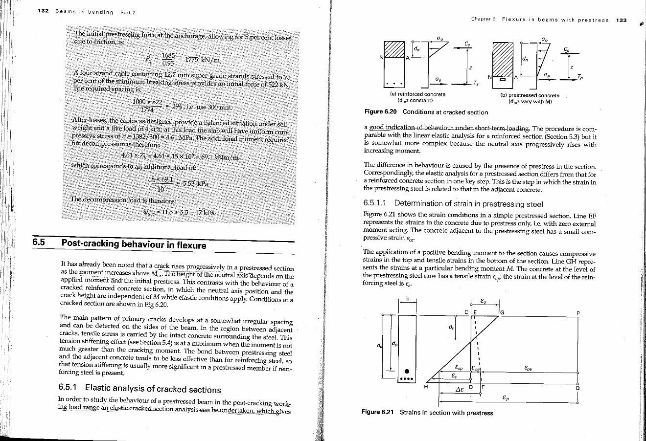
6:5.1.1 Determination of strain in prestressing steelFigure 6.21 shows the strain conditions in a simple prestressed section. Line EFrepresents the strains in the concrete due to prestress only, i.e. with zero externalmoment acting. The concrete adjacent to the prestressing steel has a small compressive strain eee'
The application of a positive bending moment to the section causes compressivestrains in the top and tensile strains in the bottom of the section. Line GH represents the strains at a particular bending moment M. The concrete at the level ofthe prestressing steel now has a tensile strain ecpi the strain at the level of the reinforcingsteel is es'
Figure 6.20 Conditions at cracked section
(b) prestressed concrete(dn,zvary with M)
(a) reinforced concrete(dn,zconstant)
Chapter 6 Flexure in beams with prestressIII
6.5.1 Elastic analysis of cracked sectionsIn order to study the behaviour of a prestressed beam in the post-cracking wm:k.:.ing load rang.ean~~on_analy-sis-ean.-be._~!taken, which gives
It has already been noted that a crack rises progressively in a prestressed sectionas_fu~",!!l:9.~~?tincreases aboveMcr.Tl1e height-of ihe-neutralaxis"aep-enm-()"ntheapplied momeiifand' the -initial'prestress, This contrasts with the behaviour of acracked reinforced concrete section, in which the neutral axis position and thecrackheight are independent ofM while elastic conditions apply. Conditions at acracked section are shown in Fig 6.20.
The main pattern of primary cracks develops at a somewhat irregular spacingand can be detected on the sides of the beam. In the region between adjacentcracks, tensile stress is carried by the intact concrete surrounding the steel. Thistension stiffening effect (seeSection5.4)is at a maximum when the moment is notmuch greater than the cracking moment. The bond between prestressing steeland the adjacent concrete tends to be less effective than for reinforcing steel, sothat tension stiffening is usually more significant in a prestressed member if reinforcing steel is present.
6.5 Post-cracking behaviour in flexure
132 Beams in bending Part 2
. ~ : i
t !