epx series power amplifiers - farnell element14 · epx series power amplifiers user manual power...
TRANSCRIPT
Order codes: AMP24 - EPX 300AMP25 - EPX 500AMP26 - EPX 800
AMP27 - EPX 1200AMP28 - EPX 2200
EPX Series Power Amplifiers
User Manual
POWER
PROTECT
I
O
CLIPCLIP
POWERCH A CH B
POWER
PROTECT
I
O
CLIPCLIP
POWERCH A CH B
POWER
PROTECT
I
O
CLIPCLIP
POWERCH A CH B
POWER
CLIPCLIP
POWERI
O
PROTECT
BR PRST
CH A CH B
POWER
CLIPCLIP
POWERI
O
PROTECT
BR PRST
CH A CH B

www.prolight.co.uk EPX Series Power Amplifiers User Manual 2
Safety advice
WARNINGFOR YOUR OWN SAFETY, PLEASE READ THIS USER MANUAL CAREFULLY BEFORE YOUR INITIAL START-UP!• Immediatelyuponreceivingthisproduct,carefullyunpackthecartonandcheckthecontents
toensurethatallthepartsarepresent.
• Beforeinitialstart-up,pleasemakesurethatthereisnodamagecausedduringtransportation.
• Shouldtherebeanydamage,consultyourdealeranddonotusetheequipment.
• Retainthecartonandallpackagingmaterials.
• Intheeventthattheequipmentmustbereturnedtothesupplier,itisimportantthattheequipmentisreturnedintheoriginalcartonandpackaging.
• Tomaintaintheequipmentingoodworkingconditionandtoensuresafeoperation,itisnecessaryfortheusertofollowthesafetyinstructionsandwarningnoteswritteninthismanual.
• Pleasenotethatdamagescausedbyusermodificationstothisequipmentarenotsubjecttowarranty.
IMPORTANT:The manufacturer will not accept liability for any resulting damages caused by the non-observance of this manual or any unauthorised modification to the equipment.
OPERATING DETERMINATIONSIfthisequipmentisoperatedinanyotherway,thanthosedescribedinthismanual,theproductmaysufferdamageandthewarrantybecomesvoid.Incorrectoperationmayleadtodangere.g:short-circuit,burnsandelectricshocksetc.
Incaseofmalfunctionthisunitshouldbereturnedforserviceorinspection.
Donotendangeryourownsafetyandthesafetyofothers!
Incorrectinstallationorusecancauseseriousdamagetopeopleand/orproperty.
• Neverletthepowercablecomeintocontactwithothercables.Handlethepowercableandallmainsvoltageconnectionswithcaution!
• Neverremovewarningorinformativelabelsfromtheequipment.
• Donotopenormodifytheequipment.
• Donotconnectthisequipmenttoadimmer-pack.
• Donotswitchtheequipmentonandoffinshortintervals,asthiswillreducethesystem’slife.
• Onlyusetheequipmentindoors.
• Donotexposetoflammablesources,liquidsorgases.
• Alwaysdisconnectthepowerfromthemainswhenequipmentisnotinuseorbeforecleaning!Onlyhandlethepowercablebytheplug.Neverpullouttheplugbypullingthepowercable.
• Makesurethattheavailablevoltageisbetween220V/240V.
• Makesurethatthepowercableisnevercrimpedordamaged.Checktheequipmentandthepowercableperiodically.
• Iftheequipmentisdroppedordamaged,disconnectthemainspowersupplyimmediately.Haveaqualifiedengineerinspecttheequipmentbeforeoperatingagain.
• Iftheequipmenthasbeenexposedtodrastictemperaturefluctuation(e.g.aftertransportation),donotswitchitonimmediately.Thearisingcondensationmightdamagetheequipment.Leavetheequipmentswitchedoffuntilithasreachedroomtemperature.
• Iftheproductfailstofunctioncorrectly,discontinueuseimmediately.Packsecurely(preferablyintheoriginalpackingmaterial),andreturntoyourdealerforservice.
• Onlyusefusesofsametypeandrating.
• Repairs,servicingandpowerconnectionmustonlybecarriedoutbyaqualifiedtechnician.THISUNITCONTAINSNOUSERSERVICEABLEPARTS.
• WARRANTY:Oneyearfromdateofpurchase.
CAUTION!KEEP THIS EQUIPMENT AWAY FROM MOISTURE, RAIN AND LIQUIDS, AND OUT OF DAMP/HUMID ENVIRONMENTS
CAUTION! TAKE CARE USING THIS EQUIPMENT!HIGH VOLTAGE-RISK OF ELECTRIC SHOCK!!

www.prolight.co.uk EPX Series Power Amplifiers User Manual 3
Product overview
Aprofessionalrangeofpoweramplifiersofferingsuperiorreliabilityandperformance,withafullrangeofpoweroptionsavailabletosuitavarietyofapplications.
•Shortcircuit,overloadandthermalprotection
•Fancooled
•Groundlift
EPX Series Power Amplifiers
Specifications EPX 300 EPX 500 EPX 800 EPX 1200 EPX 2200
Outputpower1kHz,THD+N≤0.5%
Stereo8Ω 2x90W 2x180W 2x270W 2x400W 2x850W
Stereo4Ω 2x150W 2x250W 2x400W 2x600W 2x1100W
Bridge8Ω - - - 1200W 2200W
Frequencyresponse 20Hzto20kHz±1.0dB
Inputsensitivity 0.775V/1.0V/1.44V
S/Nratio(a-weighted,RMS) >95dB>100dB
>70dBCrosstalkatratedpoweroutput(8Ωat1kHz)
>55dB >65dB
Dampingfactor(f=1kHz@8Ω) >60 >150dB >200
ProtectioncircuitsThermal,shortcircuit,overload,DCfaultprotection
&ACpowersupplyfuse
Softstart,limit,thermal,shortcircuit,overload,DCfaultprotection
&ACpowersupplyfuse
LEDindicators Power,protect&clip Power,protect,clip,stereo,parallel&bridge
ConnectorsInputs:2xphonosockets,2x1/4”jacksockets
Outputs:2xlockingspeakerconnectors,2xbindingposts
Inputs:2xXLRsockets,2x1/4”jacksocketsOutputs:2xlockingspeakerconnectors,2xbindingposts,1xlockingspeaker
bridgeconnector
Coolingsystem Low-noisecoolingfans,variablespeedfan
Powersupply AC240V/50Hz
Dimensions(HxWxD) 87x481x297mm 87x481x297mm 87x481x297mm 87x481x450mm 87x481x450mm
Weight 9.5kg 10kg 10.5kg 18kg 21kg
Ordercode AMP24 AMP25 AMP26 AMP27 AMP28
Inthebox:1 x power amplifier, 1 x power cable & 1 x user manual
POWER
PROTECT
I
O
CLIPCLIP
POWERCH A CH B
POWER
PROTECT
I
O
CLIPCLIP
POWERCH A CH B
POWER
PROTECT
I
O
CLIPCLIP
POWERCH A CH B
POWER
CLIPCLIP
POWERI
O
PROTECT
BR PRST
CH A CH B
POWER
CLIPCLIP
POWERI
O
PROTECT
BR PRST
CH A CH B
www.prolight.co.uk EPX Series Power Amplifiers User Manual 4
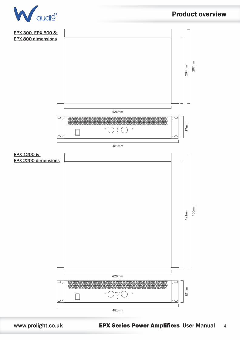
EPX 300, EPX 500 & EPX 800 dimensions
EPX 1200 & EPX 2200 dimensions
Product overview
481mm
87mm
264mm
297
mm
426mm
481mm
87mm
421
mm
450mm
426mm

www.prolight.co.uk EPX Series Power Amplifiers User Manual 5
EPX 300, EPX 500 & EPX 800 front panel
EPX 300, EPX 500 & EPX 800 rear panel
Technical specifications
01-ClipLEDs-TheseLEDsflashredtoindicatewhentheoutputoftheamplifierhasreachedthemaximum,andisrightontheedgeofclipping.Clippingisbadforspeakersandshouldbeavoided.ItisokayiftheLEDblinksoccasionally.Itmeansthatthetransientpeaksofthemusicarejusthittingthefulloutputoftheamplifier.
02-Gaincontrol-ThesetwoknobscontrolthelevelsofChannels1and2.Usually,thesecontrolsaresetallthewayup.Youmightturnthemdownslightlyifyouhavehigh-efficiencyspeakers.Also,youcouldusethemtocontrolthelevelofline-levelsourcessuchasaCDplayerconnecteddirectlytotheamplifierwithoutapre-amplifierormixer.Afteryouhavesetthelevels
forthemixer(orothersignalsource),adjustthelevelcontrolsontheamplifierasthefinaladjustmenttosettheoverallvolumeforthesystem.Instereoandmonomode,usebothlevelcontrolstocontrolthelevelsgoingtoeachspeaker.
03-PowerLED-ThisLEDilluminateswhentheamplifierisswitchedon
04-ProtectLED-IfthisLEDisilluminatedduringoperation,oneoftheprotectioncircuitsisactive.Pleasetaketheamplifieroutofoperationandhaveittested
05-Powerswitch-Pressthisswitchtostarttheoperation
POWER
PROTECT
I
O
CLIPCLIP
POWERCH A CH B
01 0205 02
0304
01
INPUTS
GROUNDLIFT
LIFT GNDB A
RIGHT LEFT
POWER AMPLIFIER
240V~50Hz
Serial no.
CAUTION!Remove the mains power before opening the unit. No user serviceable parts inside, refer to quali�ed service personnel. Protect the unit against moisture and heat. Operating temperature range 0-40°C. This product is not intended for use other than stated.
MAINS
T3.15 A
240V~50Hz
!
OUTPUTS(4Ω min.)
01-¼”jackinputs-Theseinputsallowyoutoconnect¼”unbalancedjackplugs
02-Phonoinputs-Theseinputsallowyoutoconnectunbalancedphonoplugs
03-Therearethreewaysofconnectingyourspeakers:Lockingspeakerconnectors,¼”jackorbindingposts.Theconnectorsarewiredinparallel.(e.g.Channel1bindingpost,jackandlockingspeakerconnectorsareinparallelandthesameforchannel2).
04-Powercablesocket-Thisiswhereyouconnectthedetachablepowercable.Connecttheotherendtoa240VACoutlet.
05-Groundliftswitch-Thisswitchallowsthesignalgroundorchassisgroundtobeseparatedincaseofagroundconflict.Forthehighestsafetyoftheequipment,itisrecommendedtokeepthe“groundliftswitch”intheGNDposition.IncaseofagroundconflictpleasesetthegroundliftswitchtoGNDLIFT.
0201 01 040305

www.prolight.co.uk EPX Series Power Amplifiers User Manual 6
Technical specifications
EPX 1200 & EPX 2200 front panel
01-ClipLEDs-TheseLEDsflashredtoindicatewhentheoutputoftheamplifierhasreachedthemaximum,andisrightontheedgeofclipping.Clippingisbadforspeakersandshouldbeavoided.ItisokayiftheLEDblinksoccasionally.Itmeansthatthetransientpeaksofthemusicarejusthittingthefulloutputoftheamplifier.
02-Gaincontrol-ThesetwoknobscontrolthelevelsofChannels1and2.Usually,thesecontrolsaresetallthewayup.Youmightturnthemdownslightlyifyouhavehigh-efficiencyspeakers.Also,youcouldusethemtocontrolthelevelofline-levelsourcessuchasaCDplayerconnecteddirectlytotheamplifierwithoutapre-amplifierormixer.Afteryouhavesetthelevelsforthemixer(orothersignalsource),adjusttheLevelcontrolsontheamplifierasthefinaladjustmenttosettheoverallvolumeforthesystem.Instereoandmonomode,usebothlevelcontrolstocontrolthelevelsgoingtoeachspeaker.Inbridgedmode,turnthechannel2levelcontroldown,andjustusethechannel1control.
03-PowerLED-ThisLEDilluminateswhentheamplifierisswitchedon
04-ProtectLED-IfthisLEDisilluminatedduringoperation,oneoftheprotectioncircuitsisactive.Pleasetaketheamplifieroutofoperationandhaveittested
05-StereoLED-Thisilluminatesinstereomode
06-BridgedLED-Thisilluminatesinbridgedmode
07-ParallelLED-ThisLEDilluminatesinparallelmode
08-Powerswitch-Pressthisswitchtostarttheoperation
POWER
CLIPCLIP
POWERI
O
PROTECT
BR PRST
CH A CH B
01 0208 02
0403
01
0605 07
www.prolight.co.uk EPX Series Power Amplifiers User Manual 7
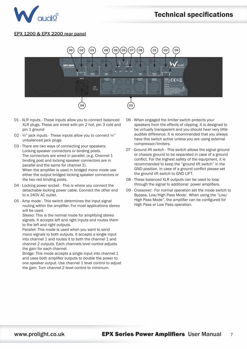
EPX 1200 & EPX 2200 rear panel
!
POWER AMPLIFIER
240V~50Hz
Serial no.
CAUTION!Remove the mains power before opening the unit. No user serviceable parts inside, refer to quali�ed service personnel. Protect the unit against moisture and heat. Operating temperature range 0-40°C. This product is not intended for use other than stated.
OUTPUTSCH-B
OUTPUTSCH-A
OUTPUTBRIDGE
T10.0 A
240V~50Hz
MAINS
GROUNDLIFT
LIFT GND
LIMITER
ON OFF
PR STBR
LOWHIGH BYPASS LOWHIGH BYPASSINPUTS
CH-BLINKCH-B
LINKCH-A
INPUTSCH-A
01-XLRinputs-TheseinputsallowyoutoconnectbalancedXLRplugs.Thesearewiredwithpin2hot,pin3coldandpin1ground
02-¼”jackinputs-Theseinputsallowyoutoconnect¼”unbalancedjackplugs
03-Therearetwowaysofconnectingyourspeakers:Lockingspeakerconnectorsorbindingposts.Theconnectorsarewiredinparallel.(e.g.Channel1bindingpostandlockingspeakerconnectorsareinparallelandthesameforchannel2).Whentheamplifierisusedinbridgedmonomodeuseeithertheoutputbridgedlockingspeakerconnectorsorthetworedbindingposts.
04-Lockingpowersocket-Thisiswhereyouconnectthedetachablelockingpowercable.Connecttheotherendtoa240VACoutlet.
05-Ampmode-Thisswitchdeterminestheinputsignalroutingwithintheamplifier.Formostapplicationsstereowillbeused.Stereo:Thisisthenormalmodeforamplifyingstereosignals.Itacceptsleftandrightinputsandroutesthemtotheleftandrightoutputs.Parallel:Thismodeisusedwhenyouwanttosendmonosignalstobothoutputs.Itacceptsasingleinputintochannel1androutesittoboththechannel1andchannel2outputs.Eachchannelslevelcontroladjuststhegainforeachchannel.Bridge:Thismodeacceptsasingleinputintochannel1andusesbothamplifieroutputstodoublethepowertoonespeakeroutput.Usechannel1levelcontroltoadjustthegain.Turnchannel2levelcontroltominimum.
06-Whenengagedthelimiterswitchprotectsyourspeakersfromtheeffectsofclipping.Itisdesignedtobevirtuallytransparentandyoushouldhearverylittleaudibledifference.Itisrecommendedthatyoualwayshavethisswitchactiveunlessyouareusingexternalcompressor/limiters.
07-Groundliftswitch-Thisswitchallowsthesignalgroundorchassisgroundtobeseparatedincaseofagroundconflict.Forthehighestsafetyoftheequipment,itisrecommendedtokeepthe“groundliftswitch”intheGNDposition.IncaseofagroundconflictpleasesetthegroundliftswitchtoGNDLIFT.
08-ThesebalancedXLRoutputscanbeusedtoloopthroughthesignaltoadditionalpoweramplifiers.
09-Crossover:FornormaloperationsetthemodeswitchtoBypass.Low/HighPassMode:Whenusingthe“Low/HighPassMode”,theamplifiercanbeconfiguredforHighPassorLowPassoperation.
04 03
02 0909 010808 0506 070102
Technical specifications
www.prolight.co.uk EPX Series Power Amplifiers User Manual 8
Operating instructions
Rack installation
TheEPSeriesisbuiltfor19”racks.Therackyouuseshouldbea‘doubledoorrack’whereyoucanopenthefrontandrearpanel.Whenmountingtheamplifierintotherack,pleasemakesurethatthereisenoughspacearoundtheamplifier.
Becarefulwhenmountingtheamplifierintotherack.Puttheheaviestproductsintothelowerpartoftherack.Beawarethatfasteningtheamplifierwithfourscrewsonthefrontpanelisnotenough.
Iftheracksarebeingtransportedorusedformobileuse,additionallyfastentheproductsby
connectingtherearbracketswiththesideorgroundbarsoftherack.Inthisway,theamplifier
cannotbepushedbackwards.Thefrontpanelisnotdesignedtoabsorbaccelerationforces
occuringduringtransportation.
Inputs
Shortcablesrunsimprovethesoundqualityremarkably.Inputcablesshouldbeshortanddirect,
sincehighfrequencieswillmostlybeabsorbedifthecablesareunnecessarilylong.Besidesthatalongercablemayleadtohummingandnoiseproblems.Ifthecablerunsareunavoidable,youshouldusebalancedcables.
Outputs
Thehighdampingfactorofyouramplifiersuppliesaclearsoundreproduction.
Unnecessarilylongandthincableswillinfluencethedampingfactorandthusthelowfrequenciesinanegativeway.Inordertosafeguardgoodsoundquality,thedampingfactorshouldliearound50.Thelongeracablehastobethethickeritshouldbe.
ConnectyourspeakersystemsviathelockingspeakerconnectorsortheBannana/Screwcombination(red+,black-)
Connection to the mains
Connecttheamplifieronlyafterhavingmadesurethatthecorrectvoltage(240V)issuppliedandthatthegroundcableisearthed.ThisproductfallsunderClass1.Donotdetachthegroundcable.
www.prolight.co.uk EPX Series Power Amplifiers User Manual 9
Operating instructions
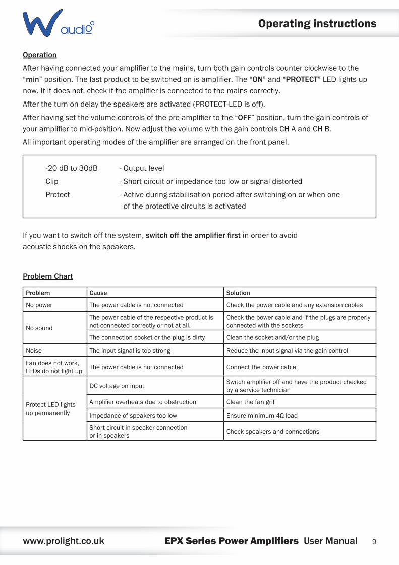
Operation
Afterhavingconnectedyouramplifiertothemains,turnbothgaincontrolscounterclockwisetothe“min”position.Thelastproducttobeswitchedonisamplifier.The“ON”and“PROTECT”LEDlightsupnow.Ifitdoesnot,checkiftheamplifierisconnectedtothemainscorrectly.
Aftertheturnondelaythespeakersareactivated(PROTECT-LEDisoff).
Afterhavingsetthevolumecontrolsofthepre-amplifiertothe“OFF”position,turnthegaincontrolsofyouramplifiertomid-position.NowadjustthevolumewiththegaincontrolsCHAandCHB.
Allimportantoperatingmodesoftheamplifierarearrangedonthefrontpanel.
Ifyouwanttoswitchoffthesystem,switch off the amplifier firstinordertoavoidacousticshocksonthespeakers.
Problem Chart
-20dBto30dB -Outputlevel
Clip -Shortcircuitorimpedancetooloworsignaldistorted
Protect -Activeduringstabilisationperiodafterswitchingonorwhenone oftheprotectivecircuitsisactivated
Problem Cause Solution
Nopower Thepowercableisnotconnected Checkthepowercableandanyextensioncables
Nosound
Thepowercableoftherespectiveproductisnotconnectedcorrectlyornotatall.
Checkthepowercableandiftheplugsareproperlyconnectedwiththesockets
Theconnectionsocketortheplugisdirty Cleanthesocketand/ortheplug
Noise Theinputsignalistoostrong Reducetheinputsignalviathegaincontrol
Fandoesnotwork,LEDsdonotlightup
Thepowercableisnotconnected Connectthepowercable
ProtectLEDlightsuppermanently
DCvoltageoninputSwitchamplifieroffandhavetheproductcheckedbyaservicetechnician
Amplifieroverheatsduetoobstruction Cleanthefangrill
Impedanceofspeakerstoolow Ensureminimum4Ωload
Shortcircuitinspeakerconnectionorinspeakers
Checkspeakersandconnections

www.prolight.co.uk EPX Series Power Amplifiers User Manual 10
Operating instructions
Cleaning and Maintenance
Werecommendafrequentcleaningoftheproduct.Pleaseuseasoftlintfreeandmoistenedcloth.Neverusealcoholorsolvents.
Therearenoserviceablepartsinsidetheproductexceptforthefuse.Maintenanceandservice
operationsareonlytobecarriedoutbyauthoriseddealers.
Replacing the fuse
Onlyreplacethefusewithafuseofthesametypeandrating.
Beforereplacingthefuse,unplugthemainscable.
Procedure:
Step 1:Openfuseholderontherearpanelwithascrewdriver.
Step 2:Removetheoldfusefromthefuseholder.
Step 3:Installthenewfuseinthefuseholder.
Step 4:Replacethefuseholderinthehousing.
Shouldyouneedanyspareparts,pleaseusegenuineparts.
Shouldyouhaveanyfurtherquestions,pleasecontactyourdealer.
CAUTION! - DANGER TO LIFEDISCONNECT FROM THE MAINS BEFORESTARTING MAINTENANCE OPERATION

www.prolight.co.uk EPX Series Power Amplifiers User Manual 11
WEEE notice
Correct Disposal of this Product (Waste Electrical & Electronic Equipment)
(Applicable in the European Union and other European countries with separate collection systems)
Thismarkingshownontheproductoritsliterature,indicatesthatitshouldnotbedisposedofwithotherhouseholdwastesattheendofitsworkinglife.Topreventpossibleharmtotheenvironmentorhumanhealthfromuncontrolledwastedisposal,pleaseseparatethisfromothertypesofwastesandrecycleitresponsiblytopromotethesustainablereuseofmaterialresources.
Householdusersshouldcontacteithertheretailerwheretheypurchasedthisproduct,ortheirlocalgovernmentoffice,fordetailsofwhereandhowtheycantakethisitemforenvironmentallysaferecycling.
Businessusersshouldcontacttheirsupplierandcheckthetermsandconditionsofthepurchasecontract.Thisproductshouldnotbemixedwithothercommercialwastesfordisposal.

www.prolight.co.uk EPX Series Power Amplifiers User Manual 12