epson rc+ 7.0 option plc function block rev
TRANSCRIPT

Rev.2 EM216S4673F
EPSON RC+ 7.0 Option
PLC Function Block

EPSON
RC
+ 7.0 Option PLC
Function Block Rev.2

EPSON RC+ 7.0 Option PLC Function Block Rev.2 i
EPSON RC+ 7.0 Option
PLC Function Block Rev.2
Copyright 2020-2021 SEIKO EPSON CORPORATION. All rights reserved.

ii EPSON RC+ 7.0 Option PLC Function Block Rev.2
FOREWORD Thank you for purchasing our robot products. This manual contains the information necessary for the correct use of the PLC Function Block. Please carefully read this manual and other related manuals before installing the robot system. Keep this manual handy for easy access at all times.
The robot system and its optional parts are shipped to our customers only after being subjected to the strictest quality controls, tests, and inspections to certify its compliance with our high performance standards. Please note that the basic performance of the product will not be exhibited if our robot system is used outside of the usage conditions and product specifications described in the manuals. This manual describes possible dangers and consequences that we can foresee. Be sure to comply with safety precautions on this manual to use our robot system safety and correctly.
TRADEMARKS Microsoft, Windows, and Windows logo are either registered trademarks or trademarks of Microsoft Corporation in the United States and/or other countries. Allen-Bradley and Studio 5000 are registered trademarks of Rockwell Automation, Inc.. CODESYS is registered trademark of CODESYS GmbH.. Other brand and product names are trademarks or registered trademarks of the respective holders.
TRADEMARK NOTATION IN THIS MANUAL Microsoft® Windows® 8 Operating system Microsoft® Windows® 10 Operating system Throughout this manual, Windows 8, and Windows 10 refer to above respective operating systems. In some cases, Windows refers generically to Windows 8, and Windows 10.
NOTICE No part of this manual may be copied or reproduced without authorization. The contents of this manual are subject to change without notice. Please notify us if you should find any errors in this manual or if you have any comments regarding its contents.
MANUFACTURER
CONTACT INFORMATION Contact information is described in “SUPPLIERS” in the first pages of the following manual:
Robot System Safety Manual Read this manual first

Table of Contents
EPSON RC+ 7.0 Option PLC Function Block Rev.2 iii
1. Introduction 1
2. Operation 1
2.1 Requirements ...........................................................................................1 2.2 Robot Controller Preparation ...................................................................1 2.3 PLC/IPC Project Preparation ...................................................................1
For Allen-Bradley ...................................................................................1 For CODESYS ......................................................................................2
2.4 Function Block Common Inputs and Outputs ..........................................2 For Allen-Bradley ...................................................................................2 For CODESYS ......................................................................................2
2.5 Function Block General Operation ..........................................................3
3. Configuring the Robot Controller 3
For Allen-Bradley ...................................................................................3 For CODESYS ......................................................................................4
4. Creating a PLC/IPC Project using Function Block 5
4.1 Creating a PLC Project using Allen-Bradley ............................................5 4.2 Creating a PLC Project using CODESYS ..............................................15
4.2.1 Procedure to Create a Project ..................................................15 4.2.2 Address to Use ..........................................................................29
5. Function Block Reference 30
5.1 Function Block for Allen-Bradley ............................................................30 SPEL_Above .......................................................................................30 SPEL_Accel ........................................................................................31 SPEL_AccelS ......................................................................................32 SPEL_Arc ............................................................................................33 SPEL_Arc3 ..........................................................................................34 SPEL_ArchGet ....................................................................................35 SPEL_ArchSet ....................................................................................36 SPEL_BaseGet ...................................................................................37 SPEL_BaseSet ....................................................................................38 SPEL_Below .......................................................................................39 SPEL_CPOff .......................................................................................40 SPEL_CPOn .......................................................................................41 SPEL_ExecCmd..................................................................................42 SPEL_FineGet ....................................................................................43 SPEL_FineSet .....................................................................................44 SPEL_Flip ...........................................................................................45 SPEL_Go ............................................................................................46 SPEL_In ..............................................................................................47
Table of Contents
iv EPSON RC+ 7.0 Option PLC Function Block Rev.2
SPEL_InertiaGet ................................................................................. 48 SPEL_InertiaSet ................................................................................. 49 SPEL_Init ............................................................................................ 50 SPEL_InW ........................................................................................... 52 SPEL_Jog ........................................................................................... 53 SPEL_Jump ........................................................................................ 54 SPEL_Jump3 ...................................................................................... 55 SPEL_Jump3CP ................................................................................. 56 SPEL_Lefty ......................................................................................... 57 SPEL_LimZ ......................................................................................... 58 SPEL_LocalGet .................................................................................. 59 SPEL_LocalSet ................................................................................... 60 SPEL_MemIn ...................................................................................... 61 SPEL_MemInW................................................................................... 62 SPEL_MemOff .................................................................................... 63 SPEL_MemOn .................................................................................... 64 SPEL_MemOut ................................................................................... 65 SPEL_MemOutW ................................................................................ 66 SPEL_MemSw .................................................................................... 67 SPEL_MotorOff ................................................................................... 68 SPEL_MotorOn ................................................................................... 69 SPEL_Move ........................................................................................ 70 SPEL_NoFlip ....................................................................................... 71 SPEL_Off ............................................................................................ 72 SPEL_On ............................................................................................ 73 SPEL_Out ........................................................................................... 74 SPEL_OutW ........................................................................................ 75 SPEL_PowerHigh ............................................................................... 76 SPEL_PowerLow ................................................................................ 77 SPEL_ResetError ............................................................................... 78 SPEL_Righty ....................................................................................... 79 SPEL_SavePoints ............................................................................... 80 SPEL_Speed ....................................................................................... 81 SPEL_SpeedS .................................................................................... 82 SPEL_Sw ............................................................................................ 83 SPEL_Teach ....................................................................................... 84 SPEL_ToolGet..................................................................................... 85 SPEL_ToolSet ..................................................................................... 86 SPEL_WeightGet ................................................................................ 87 SPEL_WeightSet ................................................................................ 88 SPEL_XYLimGet ................................................................................ 89 SPEL_XYLimSet ................................................................................. 90
5.2 Function Block for CODESYS ............................................................... 91 SPEL_Above ....................................................................................... 91

Table of Contents
EPSON RC+ 7.0 Option PLC Function Block Rev.2 v
SPEL_Accel ........................................................................................92 SPEL_AccelS ......................................................................................93 SPEL_Arc ............................................................................................94 SPEL_Arc3 ..........................................................................................95 SPEL_ArchGet ....................................................................................96 SPEL_ArchSet ....................................................................................97 SPEL_BaseGet ...................................................................................98 SPEL_BaseSet ....................................................................................99 SPEL_Below .................................................................................... 100 SPEL_CPOff .................................................................................... 101 SPEL_CPOn .................................................................................... 102 SPEL_ExecCmd............................................................................... 103 SPEL_FineGet ................................................................................. 104 SPEL_FineSet .................................................................................. 105 SPEL_Flip ........................................................................................ 106 SPEL_Go ......................................................................................... 107 SPEL_In ........................................................................................... 108 SPEL_InertiaGet .............................................................................. 109 SPEL_InertiaSet ................................................................................ 110 SPEL_Init .......................................................................................... 111 SPEL_InW ......................................................................................... 112 SPEL_Jog ......................................................................................... 113 SPEL_Jump ...................................................................................... 114 SPEL_Jump3 .................................................................................... 115 SPEL_Jump3CP ............................................................................... 116 SPEL_Lefty ....................................................................................... 117 SPEL_LimZ ....................................................................................... 118 SPEL_LocalGet ................................................................................. 119 SPEL_LocalSet ................................................................................ 120 SPEL_MemIn ................................................................................... 121 SPEL_MemInW ................................................................................ 122 SPEL_MemOff ................................................................................. 123 SPEL_MemOn ................................................................................. 124 SPEL_MemOut ................................................................................ 125 SPEL_MemOutW ............................................................................. 126 SPEL_MemSw ................................................................................. 127 SPEL_MotorOff ................................................................................ 128 SPEL_MotorOn ................................................................................ 129 SPEL_Move ..................................................................................... 130 SPEL_NoFlip .................................................................................... 131 SPEL_Off.......................................................................................... 132 SPEL_On ......................................................................................... 133 SPEL_Out ........................................................................................ 134 SPEL_OutW ..................................................................................... 135

Table of Contents
vi EPSON RC+ 7.0 Option PLC Function Block Rev.2
SPEL_PowerHigh ............................................................................. 136 SPEL_PowerLow .............................................................................. 137 SPEL_ResetError ............................................................................. 138 SPEL_Righty ..................................................................................... 139 SPEL_SavePoints ............................................................................. 140 SPEL_Speed ..................................................................................... 141 SPEL_SpeedS .................................................................................. 142 SPEL_Sw .......................................................................................... 143 SPEL_Teach ..................................................................................... 144 SPEL_ToolGet................................................................................... 145 SPEL_ToolSet ................................................................................... 146 SPEL_WeightGet .............................................................................. 147 SPEL_WeightSet .............................................................................. 148 SPEL_XYLimGet .............................................................................. 149 SPEL_XYLimSet ............................................................................... 150
6. Error Codes 151
1. Introduction
EPSON RC+ 7.0 Option PLC Function Block Rev.2 1
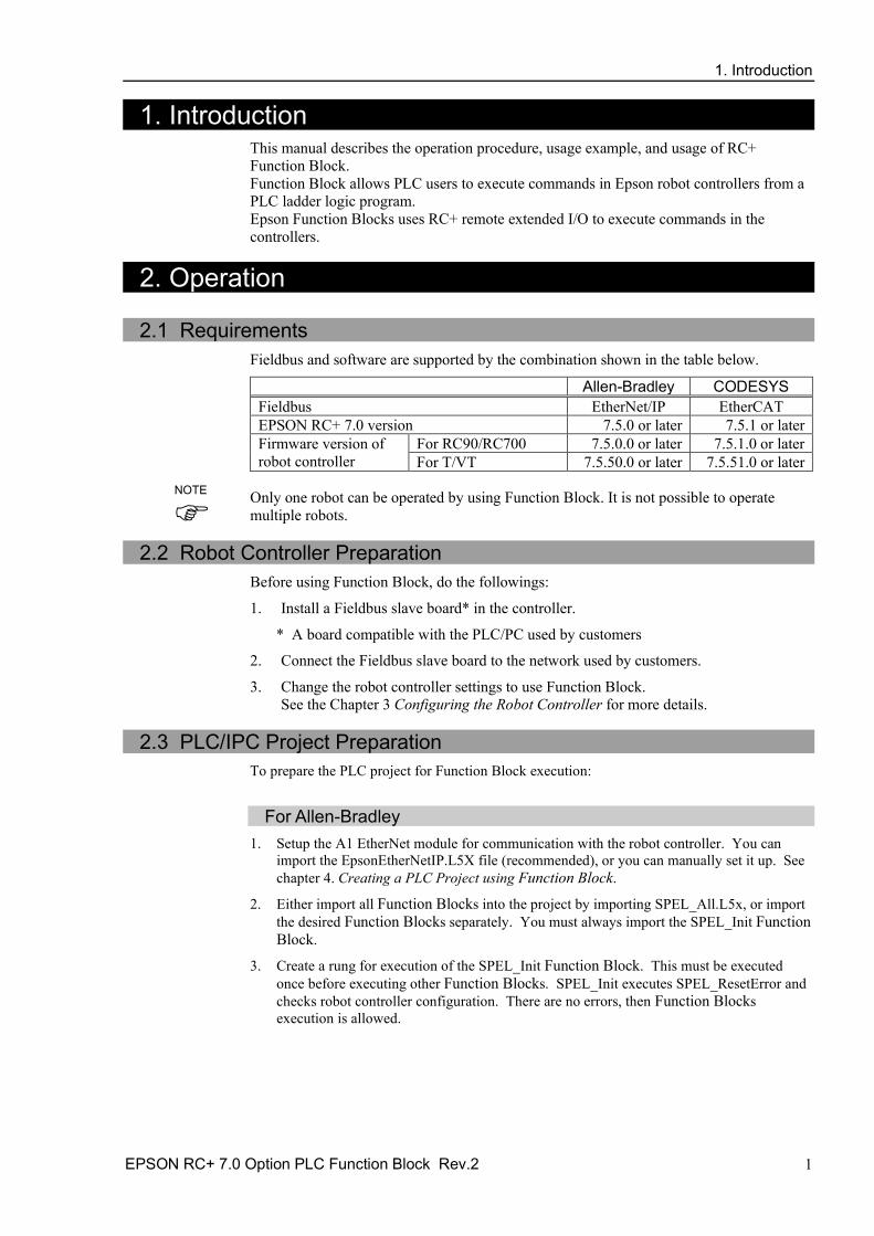
1. Introduction This manual describes the operation procedure, usage example, and usage of RC+ Function Block. Function Block allows PLC users to execute commands in Epson robot controllers from a PLC ladder logic program. Epson Function Blocks uses RC+ remote extended I/O to execute commands in the controllers.
2. Operation
2.1 Requirements Fieldbus and software are supported by the combination shown in the table below.
Allen-Bradley CODESYS Fieldbus EtherNet/IP EtherCAT EPSON RC+ 7.0 version 7.5.0 or later 7.5.1 or later Firmware version of robot controller
For RC90/RC700 7.5.0.0 or later 7.5.1.0 or later For T/VT 7.5.50.0 or later 7.5.51.0 or later
Only one robot can be operated by using Function Block. It is not possible to operate multiple robots.
2.2 Robot Controller Preparation
Before using Function Block, do the followings:
1. Install a Fieldbus slave board* in the controller.
* A board compatible with the PLC/PC used by customers
2. Connect the Fieldbus slave board to the network used by customers.
3. Change the robot controller settings to use Function Block. See the Chapter 3 Configuring the Robot Controller for more details.
2.3 PLC/IPC Project Preparation
To prepare the PLC project for Function Block execution:
For Allen-Bradley
1. Setup the A1 EtherNet module for communication with the robot controller. You can import the EpsonEtherNetIP.L5X file (recommended), or you can manually set it up. See chapter 4. Creating a PLC Project using Function Block.
2. Either import all Function Blocks into the project by importing SPEL_All.L5x, or import the desired Function Blocks separately. You must always import the SPEL_Init Function Block.
3. Create a rung for execution of the SPEL_Init Function Block. This must be executed once before executing other Function Blocks. SPEL_Init executes SPEL_ResetError and checks robot controller configuration. There are no errors, then Function Blocks execution is allowed.
NOTE

2. Operation
2 EPSON RC+ 7.0 Option PLC Function Block Rev.2
For CODESYS 1. Setup your IPC for communication with the controller.
2. Import SPEL_Library.library into the IPC program environment to use the function blocks. See the Chapter 4. Creating a PLC/IPC Project using Function Blocks for import methods.
3. You must execute SPEL_Init initially. SPEL_Init executes SPEL_ResetError and checks the controller configuration. There are no errors, then function block execution is allowed.
2.4 Function Block Common Inputs and Outputs
Each Function Block has the following common inputs and outputs:
For Allen-Bradley Inputs:
Name of Function Block
A local tag that references the name of the Function Block.
ExtInputs These are the input IO mapping. ExtOutputs These are the output IO mapping. Start This is the input that starts the Function Block.
Outputs:
InCycle BOOL output bit that indicates the status of execution of the Function Block . If this is high, then the Function Block is executing.
Done BOOL output bit that indicates the status of completion of the Function Block. If this is high, then the Function Block execution is complete.
Error BOOL output bit that indicates if an error occurred during execution.
ErrCode1 and ErrCode2
INT error codes from the robot controller. These should be 0 in normal operation, and one or both are greater than 0 when the Error bit is high.
Function Blocks have additional inputs and/or outputs. These are described separately for each Function Block in the chapter 5. Function Block Reference.
For CODESYS Inputs:
Start This is the input that starts the Function Block.
Outputs:
InCycle BOOL output bit that indicates the status of execution of the Function Block. If this is high, then the Function Block execution is complete.
Done BOOL output bit that indicates the status of completion of the Function Block. If this is high, then the Function Block execution is complete.
Error BOOL output bit that indicates if an error occurred during execution.
ErrCode1 and ErrCode2
UINT error codes from the robot controller. These should be 0 in normal operation, and one or both are greater than 0 when the Error bit is high.
Function Blocks have additional inputs and/or outputs. These are described separately for each Function Block in the chapter 5. Function Block Reference

3. Configuring the Robot Controller
EPSON RC+ 7.0 Option PLC Function Block Rev.2 3
2.5 Function Block General Operation General operation of all Function Blocks is as follows:
1. SPEL_Init must have been executed one time sucessfully before executing other function blocks.
2. Set the Start input from low to high to start execution.
3. During execution, the Done and Error output bits are set to low and the InCycle output bit is set to high.
4. After execution, the Done output bit is set to high and the InCycle output bit is set to low. If an error occurred during execution, the Error output bit is set to high, and the error code values ErrCode1 and ErrCode2 are set. See the chapter 6. Error Codes for more information.
5. If an error occurs, Function Block execution is prevented until the SPEL_ResetError Function Block is executed.
3. Configuring the Robot Controller In this chapter we will describe how to configure the robot controller Fieldbus slave to work with the PLC when using Function Blocks. Perform the following steps:
For Allen-Bradley
1. Start EPSON RC+ 7.0 on your PC. 2. Connect to the robot controller. You may need to configure a connection to the robot
controller in [Setup]-[PC to Controller Communications]. See the EPSON RC+ 7.0 User's Guide for instructions.
3. From the [Setup] menu, select [System Configuration].
4. Click [Controller]-[Inputs/Outputs]-[Fieldbus Slave]. Configure the number of input and
output bytes to 128 as shown below, then click <Apply>.
3. Configuring the Robot Controller
4 EPSON RC+ 7.0 Option PLC Function Block Rev.2
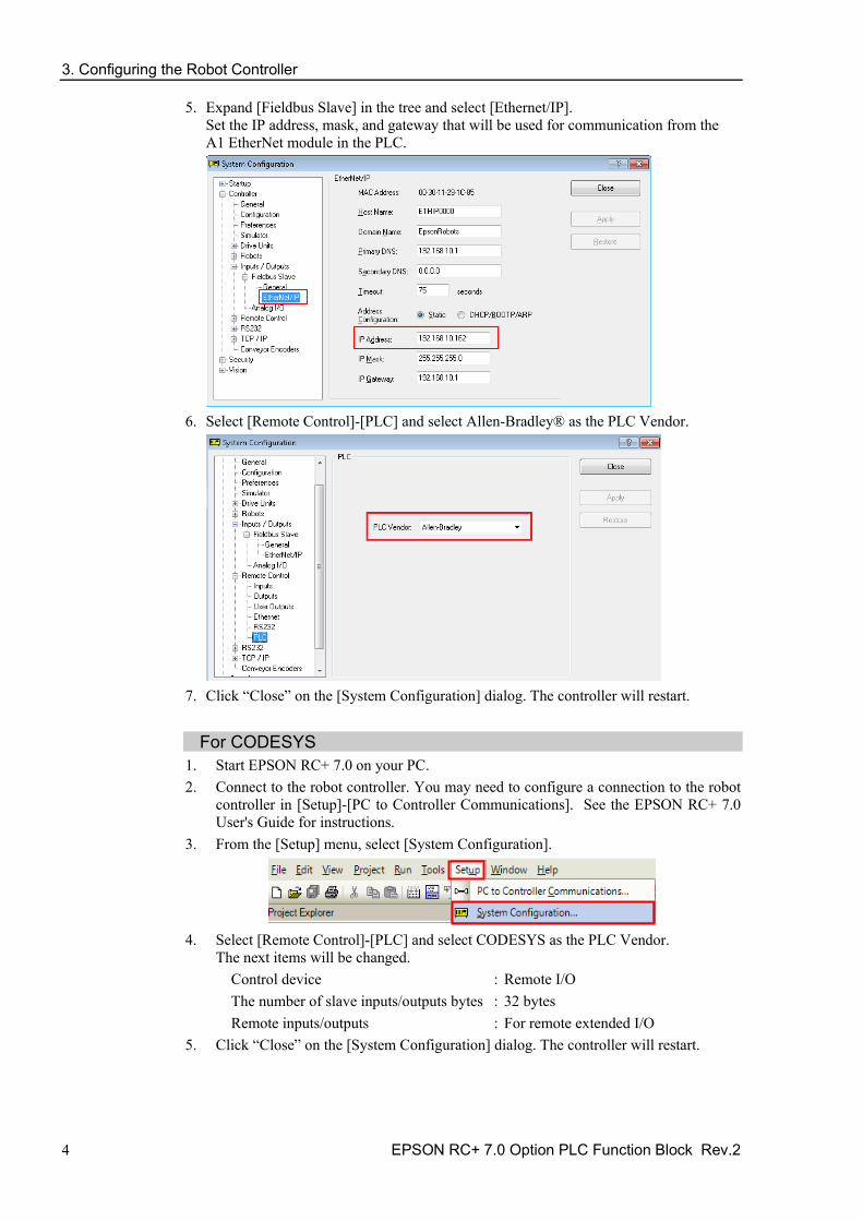
5. Expand [Fieldbus Slave] in the tree and select [Ethernet/IP]. Set the IP address, mask, and gateway that will be used for communication from the A1 EtherNet module in the PLC.
6. Select [Remote Control]-[PLC] and select Allen-Bradley® as the PLC Vendor.
7. Click “Close” on the [System Configuration] dialog. The controller will restart.
For CODESYS
1. Start EPSON RC+ 7.0 on your PC. 2. Connect to the robot controller. You may need to configure a connection to the robot
controller in [Setup]-[PC to Controller Communications]. See the EPSON RC+ 7.0 User's Guide for instructions.
3. From the [Setup] menu, select [System Configuration].
4. Select [Remote Control]-[PLC] and select CODESYS as the PLC Vendor.
The next items will be changed. Control device : Remote I/O The number of slave inputs/outputs bytes : 32 bytes Remote inputs/outputs : For remote extended I/O
5. Click “Close” on the [System Configuration] dialog. The controller will restart.
4. Creating a PLC/IPC Project using Function Block
EPSON RC+ 7.0 Option PLC Function Block Rev.2 5
4. Creating a PLC/IPC Project using Function Block
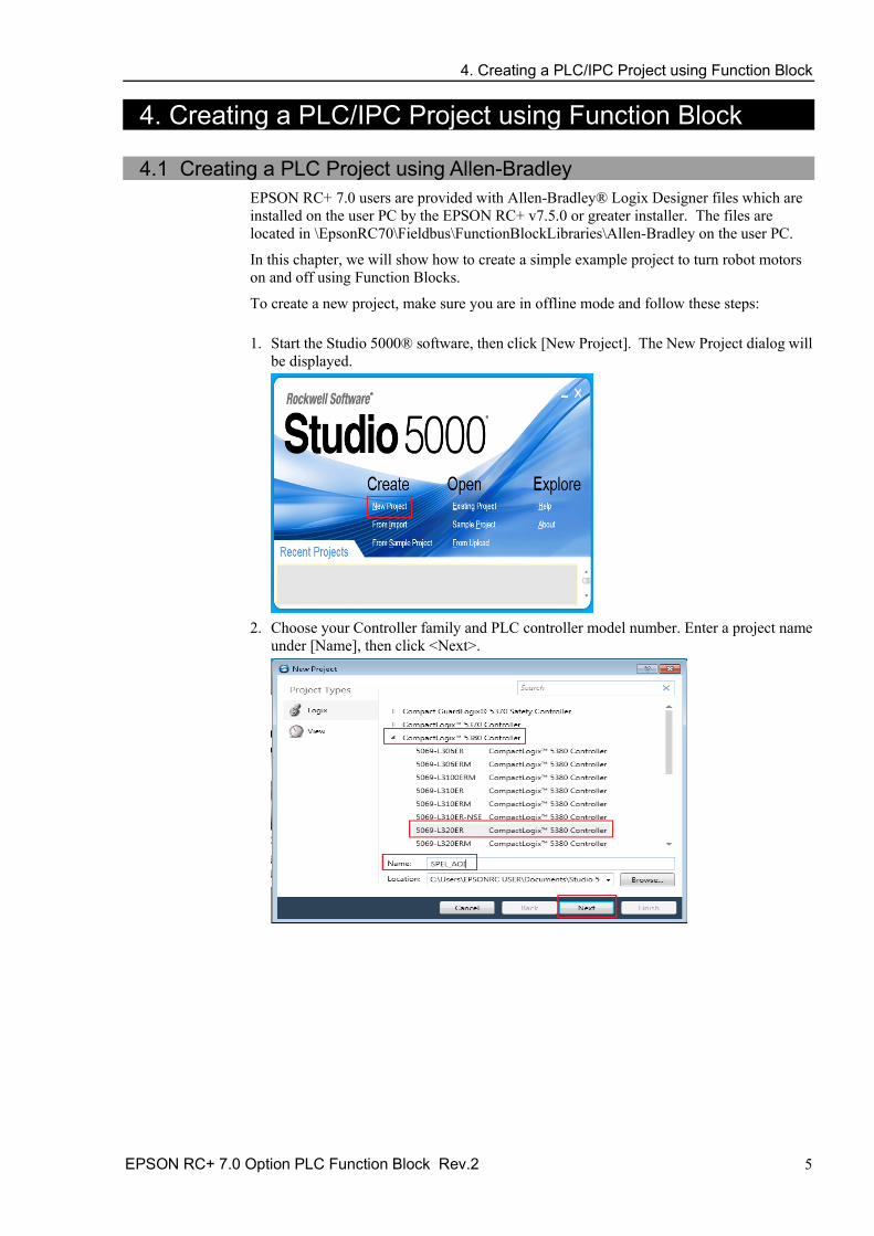
4.1 Creating a PLC Project using Allen-Bradley EPSON RC+ 7.0 users are provided with Allen-Bradley® Logix Designer files which are installed on the user PC by the EPSON RC+ v7.5.0 or greater installer. The files are located in \EpsonRC70\Fieldbus\FunctionBlockLibraries\Allen-Bradley on the user PC.
In this chapter, we will show how to create a simple example project to turn robot motors on and off using Function Blocks.
To create a new project, make sure you are in offline mode and follow these steps:
1. Start the Studio 5000® software, then click [New Project]. The New Project dialog will be displayed.
2. Choose your Controller family and PLC controller model number. Enter a project name
under [Name], then click <Next>.

4. Creating a PLC/IPC Project using Function Block
6 EPSON RC+ 7.0 Option PLC Function Block Rev.2
3. The dialog shown below will be displayed. Leave all choices as default, then click <Finish>.
4. You have just created a new empty PLC project
5. Now you need to add and configure the Ethernet module for communications with the
robot controller. There are two methods: Import the file EpsonEtherNetIP.L5X, or perform manual configuration.
4. Creating a PLC/IPC Project using Function Block
EPSON RC+ 7.0 Option PLC Function Block Rev.2 7
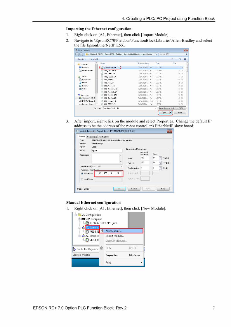
Importing the Ethernet configuration 1. Right click on [A1, Ethernet], then click [Import Module]. 2. Navigate to \EpsonRC70\Fieldbus\FunctionBlockLibraries\Allen-Bradley and select
the file EpsonEtherNetIP.L5X.
<< Windows7_OS(C:) ▸ EpsonRC70 ▸ Fieldbus ▸ FunctionBlockLibraries ▸ Allen-Bradley
3. After import, right-click on the module and select Properties. Change the default IP
address to be the address of the robot controller's EtherNetIP slave board.
Manual Ethernet configuration 1. Right click on [A1, Ethernet], then click [New Module].

4. Creating a PLC/IPC Project using Function Block
8 EPSON RC+ 7.0 Option PLC Function Block Rev.2
2. Type in “generic” in the search field. Click “ETHERNET MODULE” under catalog number, then click <Create>.
3. Enter the values as shown, and use the IP address of the robot controller EtherNet/IP
slave, then click <OK>.
4. Click <OK> on the next window.
Saving your project at this stage is a good idea. When creating a new Ethernet module, please note that connection parameter values should match your robot controller values.

4. Creating a PLC/IPC Project using Function Block
EPSON RC+ 7.0 Option PLC Function Block Rev.2 9
Import Function Blocks into the new project 1. Now you need to import Function Blocks in the new project. For this example, you
will import all Function Blocks. You can also import individual Function Blocks. To do this, right click on [Add-On Instructions] folder from [Controller Organizer], click [Import Add-On Instruction].
2. Navigate to \EpsonRC70\Fieldbus\FunctionBlockLibraries\Allen-Bradley, then
select “SPEL_All.L5X” file and click <Open>.
<< Windows7_OS(C:) ▸ EpsonRC70 ▸ Fieldbus ▸ FunctionBlockLibraries ▸ Alle n-Bradley
4. Creating a PLC/IPC Project using Function Block
10 EPSON RC+ 7.0 Option PLC Function Block Rev.2
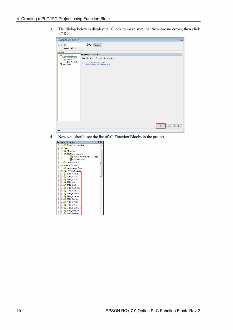
3. The dialog below is displayed. Check to make sure that there are no errors, then click <OK>.
4. Now you should see the list of all Function Blocks in the project.

4. Creating a PLC/IPC Project using Function Block
EPSON RC+ 7.0 Option PLC Function Block Rev.2 11
5. Now you can create a program. 5-1. Expand [MainProgram], then double click on [MainRoutine]. 5-2. Click [Favorites] tab, add 5 extra rungs. Then drag “Examine On” and “Output
Energize” to rung 0, 2 and 4. 5-3. Click [Add-On] tab, drag “SPEL_Init” to rung 1, “SPEL_MotorOn” to rung 3,
and “SPEL_MotorOff” to rung 5, like shown below.

4. Creating a PLC/IPC Project using Function Block
12 EPSON RC+ 7.0 Option PLC Function Block Rev.2
6. In rung 0, double click at [?] of “Examine On”, type in the name of the variable. In this case we will use “InitSwitch”.
7. Do the same step as above, in rung 0, double click on [?] of the “Output Energize”, and
type “InitCoil”. 8. Right click on [InitSwitch], click on [New “InitSwitch”], then click <Create>, as shown
below.
9. Create new variable “InitCoil” same method used in “InitSwitch”. 10. Do same steps in 6 for rung 2 and 4 to create new variables. Use variable name
“MotorOnSwitch”, “MotorOnCoil” for rung 2, and “MotorOffSwitch”, “MotorOffCoil” for rung 4.
11. Now we configure SPEL_Init Function Block inputs. 11-1. Inside “SPEL_Init” block, click [?] to the right of [SPE_Init], and type “Init”. 11-2. Right click on [Init], choose [New “Init”]. then click <Create>.
“Init” will be the name of the structure that holds all internal variable of “SPEL_Init” Function Block.
11-3. Click [?] next to “Start”, type “InitCoil”, you do not need to create a new variable.

4. Creating a PLC/IPC Project using Function Block
EPSON RC+ 7.0 Option PLC Function Block Rev.2 13
11-4. Click [?] next to [ExtInputs], type “Ep”, it will auto populate, press <Enter>.
11-5. Do same step to [ExtOutputs]. “SPEL_Init” is now configured and the rung lines
should change from red to blue. 11-6. Do the same steps as in 11-1 to 11-2 for rung 3 and 5. Choose “MotorOn” for
rung 3, “MotorOff” for rung 5. 11-7. Do the same steps as in 11-3 for rung 3 and 5. Use “MotorOnCoil” for rung 3,
“MotorOffCoil” for rung 5. 12. The program is now complete. Save the project. 13. Click the down arrow right to [Path] to choose communication path with controller.
In this example I am using USB to connect my PC to the PLC controller.
14. Double click on “USB” to close the window, then click <Download> in the next window to transfer program to PLC controller.
15. Click <Yes> in the next window if prompted to change PLC into “Remote Run” mode,
like shown below.
4. Creating a PLC/IPC Project using Function Block
14 EPSON RC+ 7.0 Option PLC Function Block Rev.2
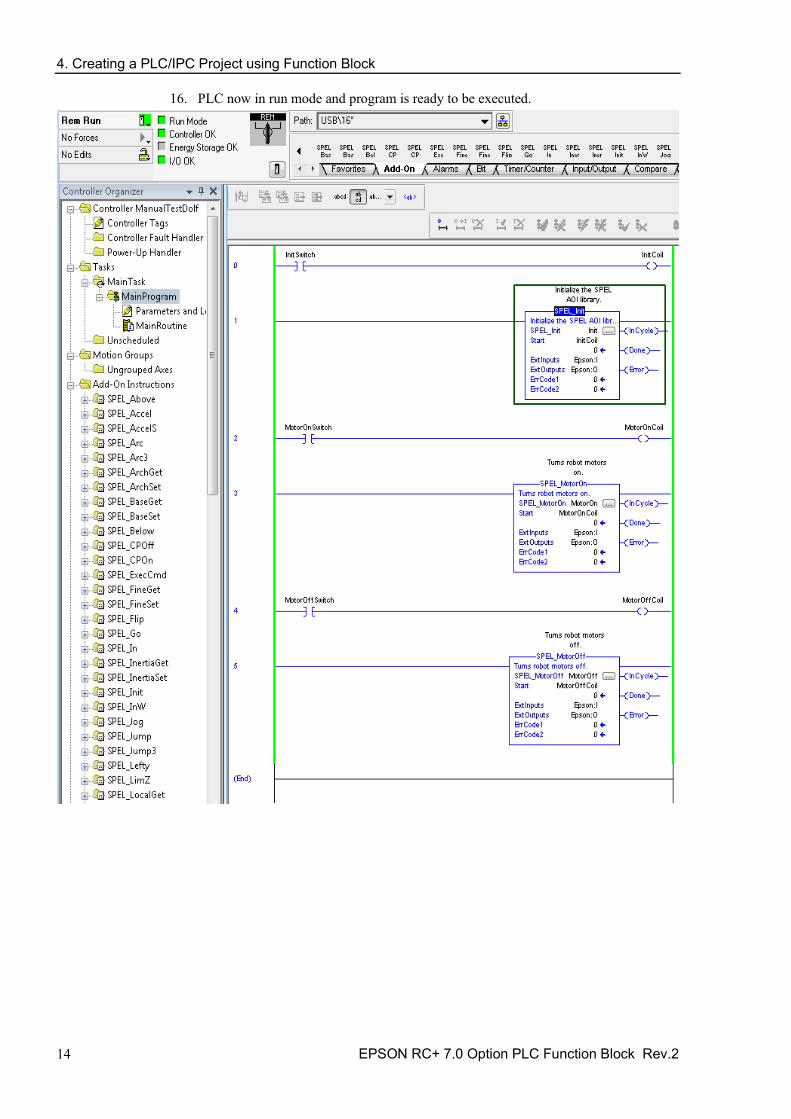
16. PLC now in run mode and program is ready to be executed.

4. Creating a PLC/IPC Project using Function Block
EPSON RC+ 7.0 Option PLC Function Block Rev.2 15
4.2 Creating a PLC Project using CODESYS 4.2.1 Procedure to Create a Project
In EPSON RC+ 7.0 Ver.7.5.1 or later, a CODESYS function block library is installed in the following folder:
\EpsonRC70\Fieldbus\FunctionBlockLibraries\CODESYS
In this section, we will show how to create a simple example program to turn robot motors on and off.
1. First, create a new project.
1-1. Start the CODESYS, then click [New Project].
1-2. Select [Projects]-[Standard project]. Enter a project name and save location, then click < OK>.
1-3. Select the appropriate device and [Ladder Logic Diagram] and click <OK>.

4. Creating a PLC/IPC Project using Function Block
16 EPSON RC+ 7.0 Option PLC Function Block Rev.2
1-4. You have just created a new empty project.
2. Now you need to import a CODESYS function block library in the new project. 2-1. Double click [Library Manager].
Then, click [Library Repository].
2-2. Click <Install>.

4. Creating a PLC/IPC Project using Function Block
EPSON RC+ 7.0 Option PLC Function Block Rev.2 17
2-3. Select the “SPEL_Library.compiled-library” file provided by EPSON and click <Open>. The file is in \EpsonRC70\Fieldbus\FunctionBlockLibraries\CODESYS folder.
2-4. Make sure that there is “SPEL Library” in [Miscellaneous].
2-5. Click [Add Library] in [Library Manager].

4. Creating a PLC/IPC Project using Function Block
18 EPSON RC+ 7.0 Option PLC Function Block Rev.2
2-6. Select [SPEL Library], then click <OK>.
2-7. Function Blocks are installed.

4. Creating a PLC/IPC Project using Function Block
EPSON RC+ 7.0 Option PLC Function Block Rev.2 19
3. Then, create a program. 3-1. Double click [PLC_PRG] to display the program screen.
Then, drag and drop three [Box] to the program screen.
3-2. Click [???] in Box. Then, click <...> next to [???].
3-3. Select [SPEL_Init] from the list of the function blocks, then click <OK>.
3-4. The name of the function block is displayed. Press the <Enter> key.
4. Creating a PLC/IPC Project using Function Block
20 EPSON RC+ 7.0 Option PLC Function Block Rev.2
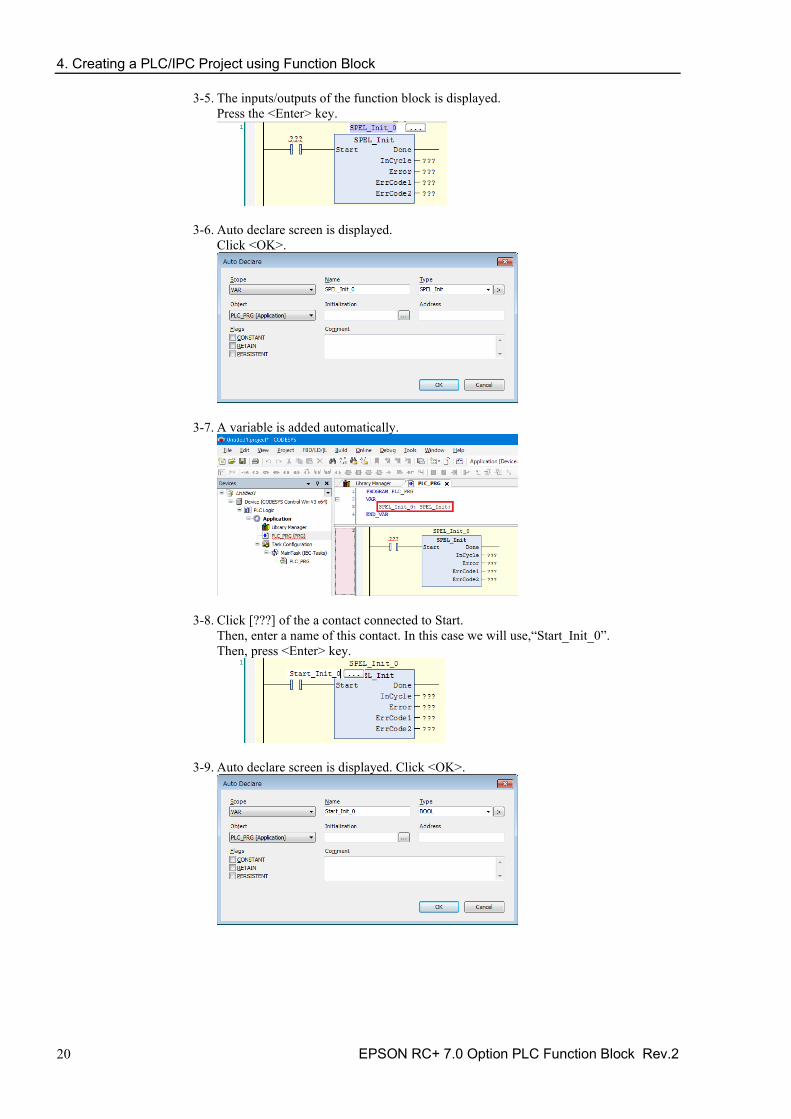
3-5. The inputs/outputs of the function block is displayed. Press the <Enter> key.
3-6. Auto declare screen is displayed. Click <OK>.
3-7. A variable is added automatically.
3-8. Click [???] of the a contact connected to Start. Then, enter a name of this contact. In this case we will use,“Start_Init_0”. Then, press <Enter> key.
3-9. Auto declare screen is displayed. Click <OK>.

4. Creating a PLC/IPC Project using Function Block
EPSON RC+ 7.0 Option PLC Function Block Rev.2 21
3-10. A variable is added automatically.
3-11. Follow the same procedure to change all [???] as follows.
4. Then, prepare to connect with a robot. 4.1 Right click [Device], then click [Add Device].
4. Creating a PLC/IPC Project using Function Block
22 EPSON RC+ 7.0 Option PLC Function Block Rev.2
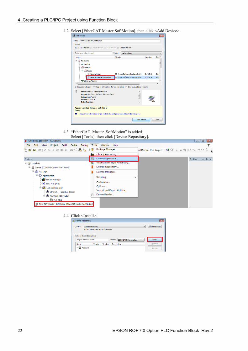
4.2 Select [EtherCAT Master SoftMotion], then click <Add Device>.
4.3 “EtherCAT_Master_SoftMotion” is added. Select [Tools], then click [Device Repository].
4.4 Click <Install>.

4. Creating a PLC/IPC Project using Function Block
EPSON RC+ 7.0 Option PLC Function Block Rev.2 23
4.5 Select the configuration file according to the robot to be used. The configuration file is in the following folder: \EpsonRC70\Fieldbus\EtherCAT In this case we will select “EPSN_TSERIES_ECT_V2.3_for_OMRON_rev2.xml”, then click <Open>.
4.6 The configuration file has been read and “TSERIES EtherCAT Slave” is displayed.
4. Creating a PLC/IPC Project using Function Block
24 EPSON RC+ 7.0 Option PLC Function Block Rev.2
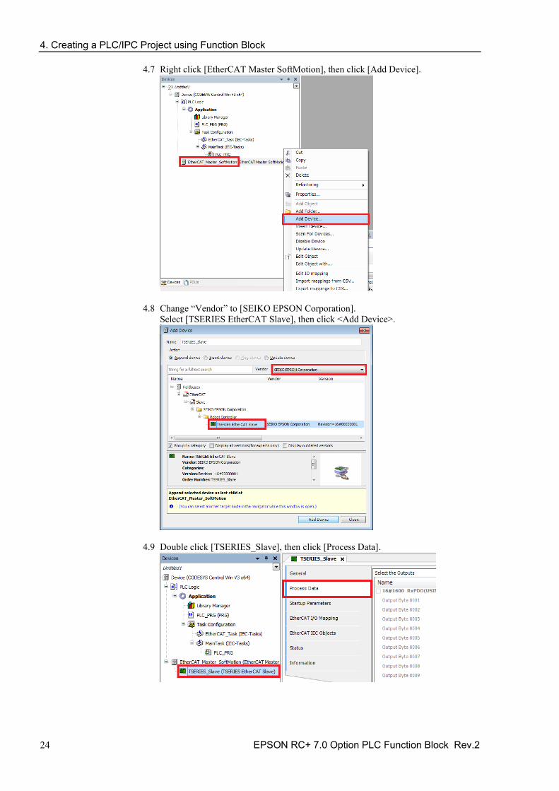
4.7 Right click [EtherCAT Master SoftMotion], then click [Add Device].
4.8 Change “Vendor” to [SEIKO EPSON Corporation]. Select [TSERIES EtherCAT Slave], then click <Add Device>.
4.9 Double click [TSERIES_Slave], then click [Process Data].

4. Creating a PLC/IPC Project using Function Block
EPSON RC+ 7.0 Option PLC Function Block Rev.2 25
4.10 Have the check boxes the same as the image below. Use “32byte” for the function blocks to communicate with controllers.
5. Execute function blocks. 5.1 Right click the PLC on the task bar or system tray, then click [Start PLC].
Check that the PLC display has changed.
5.2 Double click [Device], then click [Communication Settings] - [Scan Network].
4. Creating a PLC/IPC Project using Function Block
26 EPSON RC+ 7.0 Option PLC Function Block Rev.2
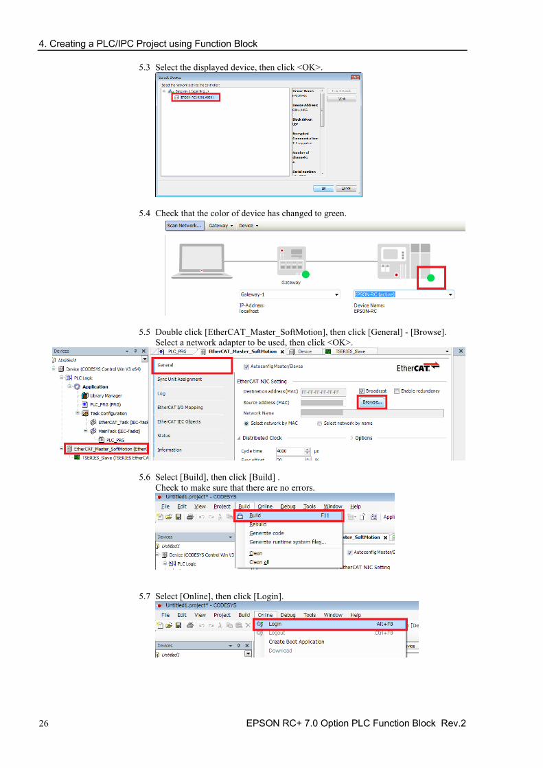
5.3 Select the displayed device, then click <OK>.
5.4 Check that the color of device has changed to green.
5.5 Double click [EtherCAT_Master_SoftMotion], then click [General] - [Browse]. Select a network adapter to be used, then click <OK>.
5.6 Select [Build], then click [Build] . Check to make sure that there are no errors.
5.7 Select [Online], then click [Login].

4. Creating a PLC/IPC Project using Function Block
EPSON RC+ 7.0 Option PLC Function Block Rev.2 27
5.8 Select [Debug], then click [Start].
5.9 Check that the green cycle is displayed on the left of “TSERIES_Slave”. Double click the a contact of SPEL_Init, then “<TRUE>” is displayed. Then, right click anywhere and click [Write All Values of ‘Device.Application’] to write values.
4. Creating a PLC/IPC Project using Function Block
28 EPSON RC+ 7.0 Option PLC Function Block Rev.2
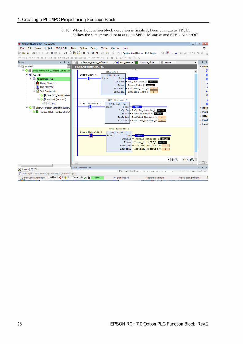
5.10 When the function block execution is finished, Done changes to TRUE. Follow the same procedure to execute SPEL_MotorOn and SPEL_MotorOff.

4. Creating a PLC/IPC Project using Function Block
EPSON RC+ 7.0 Option PLC Function Block Rev.2 29
4.2.2 Address to Use Use a “Static Address” in CODESYS Function Block. You cannot change the address. You cannot use the same address as other devices. Beware of “Duplicating Addresses” in a PLC project.
In Function Block, the following addresses are used. Input address: 0.0 ~ 31.7 Output address: 0.0 ~ 31.7
Name Address Allocation for robot In_ExtCmdGet %IX0.0 0th Bit of Byte0 In_ExtRespSet %IX0.1 1st Bit of Byte0 In_ExtCmdResult %IX0.2 2nd Bit of Byte0 In_ExtError %IX0.3 3rd Bit of Byte0 In_ExtResp_W0 %IW1 Byte2, Byte3 In_ExtResp_W1 %IW2 Byte4, Byte5 In_ExtResp_W2 %IW3 Byte6, Byte7 In_ExtResp_W3 %IW4 Byte8, Byte9 In_ExtResp_W4 %IW5 Byte10, Byte11 In_ExtResp_W5 %IW6 Byte12, Byte13 In_ExtResp_W6 %IW7 Byte14, Byte15 In_ExtResp_W7 %IW8 Byte16, Byte17 Out_ExtCmdSet %QX0.0 0th Bit of Byte0 Out_ExtRespGet %QX0.1 1st Bit of Byte0 Out_ExtCmdReset %QX0.2 2nd Bit of Byte0 Out_ExtCmd_W0 %QW1 Byte2, Byte3 Out_ExtCmd_W1 %QW2 Byte4, Byte5 Out_ExtCmd_W2 %QW3 Byte6, Byte7 Out_ExtCmd_W3 %QW4 Byte8, Byte9 Out_ExtCmd_W4 %QW5 Byte10, Byte11 Out_ExtCmd_W5 %QW6 Byte12, Byte13 Out_ExtCmd_W6 %QW7 Byte14, Byte15 Out_ExtCmd_W7 %QW8 Byte16, Byte17
NOTE
NOTE

5. Function Block Reference
30 EPSON RC+ 7.0 Option PLC Function Block Rev.2
5. Function Block Reference In this chapter each Function Block is described.
For Function Block operation in general, refer to section 2.5 Function Block General Operation.
For each Function Block in the Operation section, there is also a referal to the corresponding SPEL+ command in the SPEL+ Language Reference manual which has more details about the command.
Each Function Block has a simple example.
5.1 Function Block for Allen-Bradley
SPEL_Above
Description Sets the elbow orientation of the specified point to Above.
Common inputs and Outputs Refer to section 2.4 Function Block Common Inputs and Outputs.
Inputs Point INT point number to set its orientation to ABOVE.
Operation Refer to section 2.5 Function Block General Operation.
Refer to Elbow Statement in the SPEL+ Language Reference manual.
Example To set P0 orientation to Above, set [Point] to “0”, as shown below.

5. Function Block Reference
EPSON RC+ 7.0 Option PLC Function Block Rev.2 31
SPEL_Accel Description Sets the point to point acceleration and deceleration. Specifies the ratio (%) of the maximum acceleration/deceleration using an integer equals to or greater than 1.
Common inputs and Outputs Refer to section 2.4 Function Block Common Inputs and Outputs.
Inputs Accel INT value of acceleration as percentage. Decel INT value of deceleration as percentage.
Operation Refer to section 2.5 Function Block General Operation.
Refer to Accel Statement in the SPEL+ Language Reference manual.
Example To set acceleration to 50% and deceleration to 50%, set [Accel] to “50” and [Decel] to “50”, as shown below.
5. Function Block Reference
32 EPSON RC+ 7.0 Option PLC Function Block Rev.2
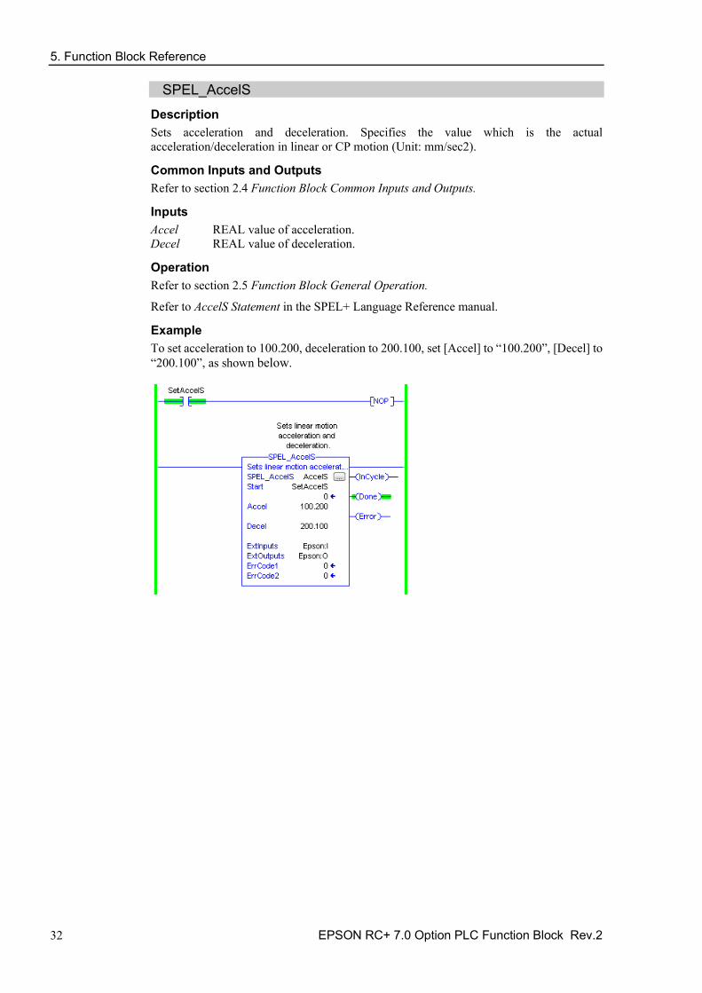
SPEL_AccelS Description Sets acceleration and deceleration. Specifies the value which is the actual acceleration/deceleration in linear or CP motion (Unit: mm/sec2).
Common Inputs and Outputs Refer to section 2.4 Function Block Common Inputs and Outputs.
Inputs Accel REAL value of acceleration. Decel REAL value of deceleration.
Operation Refer to section 2.5 Function Block General Operation.
Refer to AccelS Statement in the SPEL+ Language Reference manual.
Example To set acceleration to 100.200, deceleration to 200.100, set [Accel] to “100.200”, [Decel] to “200.100”, as shown below.

5. Function Block Reference
EPSON RC+ 7.0 Option PLC Function Block Rev.2 33
SPEL_Arc Description Moves the arm from the current position to the specified position in circular interpolation motion on XY plane face.
Common Inputs and Outputs Refer to section 2.4 Function Block Common Inputs and Outputs.
Inputs midPoint INT middle point in Arc command. endPoint INT end point in Arc command.
Operation Refer to section 2.5 Function Block General Operation.
Refer to Arc Statement in the SPEL+ Language Reference manual.
Example To move from current position passing through P2 and ending at P3, in a circular motion.

5. Function Block Reference
34 EPSON RC+ 7.0 Option PLC Function Block Rev.2
SPEL_Arc3 Description Moves the arm from the current position to the specified position in circular interpolation in 3 dimensions.
Common Inputs and Outputs Refer to section 2.4 Function Block Common Inputs and Outputs.
Inputs midPoint INT middle point in Arc3 command. endPoint INT end point in Arc3 command.
Operation Refer to section 2.5 Function Block General Operation.
Refer to Arc3 Statement in the SPEL+ Language Reference manual.
Example To move from current position passing through P1 and ending at P2, in a circular motion.
5. Function Block Reference
EPSON RC+ 7.0 Option PLC Function Block Rev.2 35
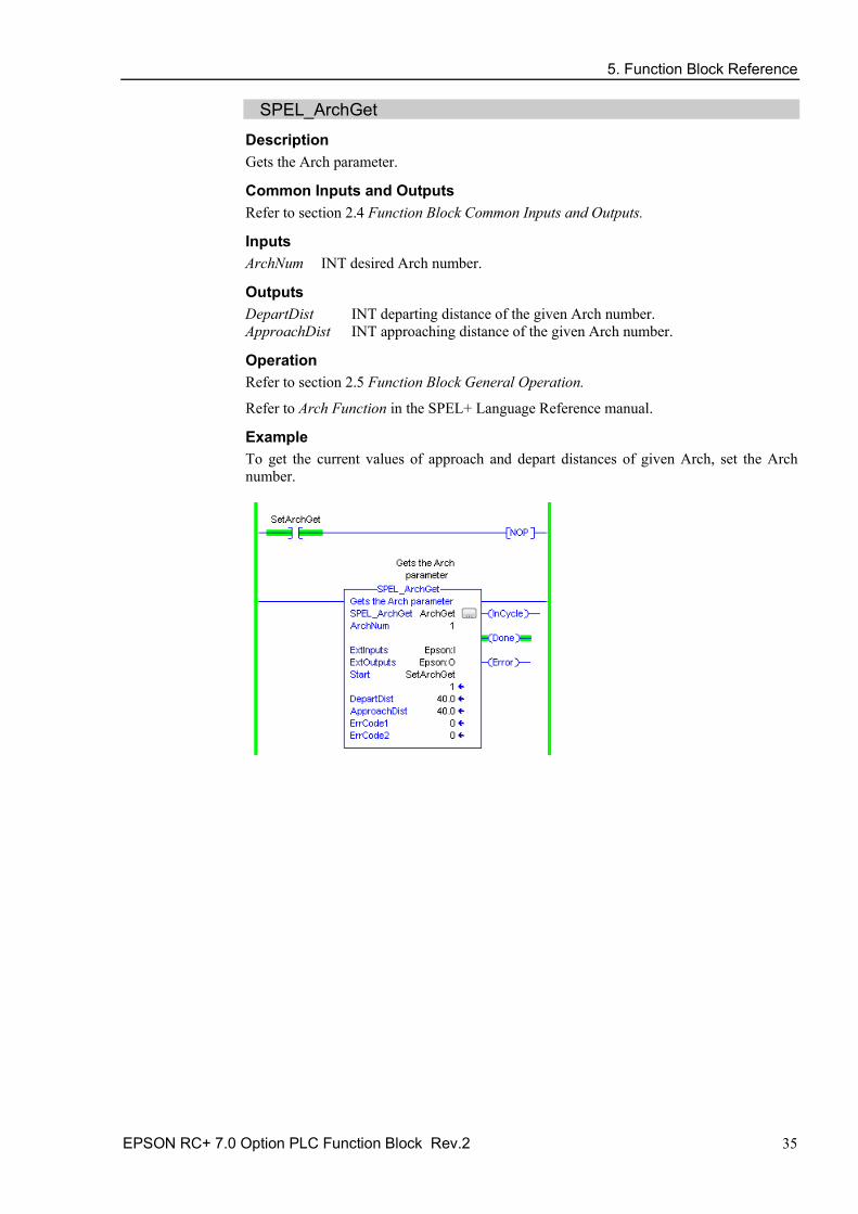
SPEL_ArchGet Description Gets the Arch parameter.
Common Inputs and Outputs Refer to section 2.4 Function Block Common Inputs and Outputs.
Inputs ArchNum INT desired Arch number.
Outputs DepartDist INT departing distance of the given Arch number. ApproachDist INT approaching distance of the given Arch number.
Operation Refer to section 2.5 Function Block General Operation.
Refer to Arch Function in the SPEL+ Language Reference manual.
Example To get the current values of approach and depart distances of given Arch, set the Arch number.

5. Function Block Reference
36 EPSON RC+ 7.0 Option PLC Function Block Rev.2
SPEL_ArchSet Description Sets the Arch parameter.
Common Inputs and Outputs Refer to section 2.4 Function Block Common Inputs and Outputs.
Inputs ArchNum INT desired Arch number. DepartDist REAL departing distance of the given Arch number. ApproachDist REAL approaching distance of the given Arch number.
Operation Refer to section 2.5 Function Block General Operation.
Refer to Arch Statement in the SPEL+ Language Reference manual.
Example To set 60.0, 60.0 as depart and approach distances respectively of Arch 2, see below.

5. Function Block Reference
EPSON RC+ 7.0 Option PLC Function Block Rev.2 37
SPEL_BaseGet Description Gets the base coordinate system.
Common Inputs and Outputs Refer to section 2.4 Function Block Common Inputs and Outputs.
Inputs NumAxes INT number of robot axes.
For a SCARA robot, use 4. For a 6-axis robot, use 6.
Outputs BaseX REAL base value of coordinate X. BaseY REAL base value of coordinate Y. BaseZ REAL base value of coordinate Z. BaseU REAL base value of coordinate U. BaseV REAL base value of coordinate V. BaseW REAL base value of coordinate W.
Operation Refer to section 2.5 Function Block General Operation.
Refer to Base Statement in the SPEL+ Language Reference manual.
Example To get the base values of X through W coordinates for SCARA robot, plug 4 for NumAxes. Base values will update as shown below.
5. Function Block Reference
38 EPSON RC+ 7.0 Option PLC Function Block Rev.2
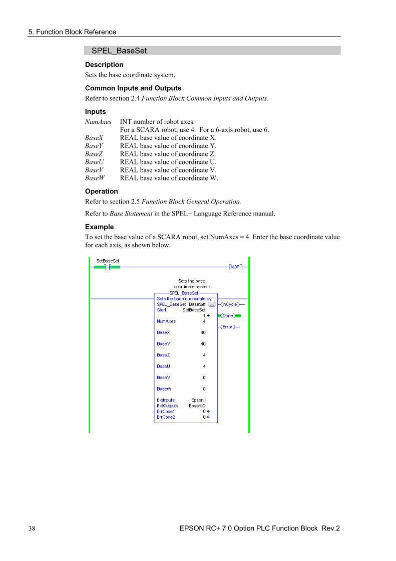
SPEL_BaseSet Description Sets the base coordinate system.
Common Inputs and Outputs Refer to section 2.4 Function Block Common Inputs and Outputs.
Inputs NumAxes INT number of robot axes.
For a SCARA robot, use 4. For a 6-axis robot, use 6. BaseX REAL base value of coordinate X. BaseY REAL base value of coordinate Y. BaseZ REAL base value of coordinate Z. BaseU REAL base value of coordinate U. BaseV REAL base value of coordinate V. BaseW REAL base value of coordinate W.
Operation Refer to section 2.5 Function Block General Operation.
Refer to Base Statement in the SPEL+ Language Reference manual.
Example To set the base value of a SCARA robot, set NumAxes = 4. Enter the base coordinate value for each axis, as shown below.

5. Function Block Reference
EPSON RC+ 7.0 Option PLC Function Block Rev.2 39
SPEL_Below Description Sets the elbow orientation of the specified point to Below.
Common Inputs and Outputs Refer to section 2.4 Function Block Common Inputs and Outputs.
Inputs Point INT desired point number.
Operation Refer to section 2.5 Function Block General Operation.
Refer to Elbow Statement in the SPEL+ Language Reference manual.
Example To set orientation of P2 to below, enter 2 as point. As shown below.

5. Function Block Reference
40 EPSON RC+ 7.0 Option PLC Function Block Rev.2
SPEL_CPOff Description Turns off Continuous Path parameter.
Common Inputs and Outputs Refer to section 2.4 Function Block Common Inputs and Outputs.
Operation Refer to section 2.5 Function Block General Operation.
Refer to CP Statement in the SPEL+ Language Reference manual.
Example To set CP to off, run the Function Block like as shown below.

5. Function Block Reference
EPSON RC+ 7.0 Option PLC Function Block Rev.2 41
SPEL_CPOn Description Turns on Continuous Path parameter.
Common Inputs and Outputs Refer to section 2.4 Function Block Common Inputs and Outputs.
Operation Refer to section 2.5 Function Block General Operation.
Refer to CP Statement in the SPEL+ Language Reference manual.
Example To set CP to On, run the Function Block as shown below.

5. Function Block Reference
42 EPSON RC+ 7.0 Option PLC Function Block Rev.2
SPEL_ExecCmd Description The SPEL_ExecCmd Function Block is used by other Function Blocks to execute a command in the robot controller.

5. Function Block Reference
EPSON RC+ 7.0 Option PLC Function Block Rev.2 43
SPEL_FineGet Description Gets the setting of positioning end judgement range for all joints.
Outputs Axis INT position accuracy for each joint in encoder pulses.
Operation Refer to section 2.5 Function Block General Operation.
Refer to Fine Function in the SPEL+ Language Reference manual.
Example To get the position accuracy for the robot, run the Function Block as shown below.

5. Function Block Reference
44 EPSON RC+ 7.0 Option PLC Function Block Rev.2
SPEL_FineSet Description Sets the positioning end judgement range for all joints.
Common Inputs and Outputs Refer to section 2.4 Function Block Common Inputs and Outputs.
Inputs Axis1..Axis6 INT position accuracy for each joint in encoder pulses.
Operation Refer to section 2.5 Function Block General Operation.
Refer to Fine Statement in the SPEL+ Language Reference manual.
Example To set the position accuracy for the robot, enter the Axis values and run the Function Block as shown below.

5. Function Block Reference
EPSON RC+ 7.0 Option PLC Function Block Rev.2 45
SPEL_Flip Description Sets the wrist orientation of the specified point to Flip.
Common Inputs and Outputs Refer to section 2.4 Function Block Common Inputs and Outputs.
Inputs Point INT desired point number.
Operation Refer to section 2.5 Function Block General Operation.
Refer to Wrist Statement in the SPEL+ Language Reference manual.
Example To set orientation of robot point P2 to flip, enter 2 as the point number and run the Function Block as shown below.

5. Function Block Reference
46 EPSON RC+ 7.0 Option PLC Function Block Rev.2
SPEL_Go Description Moves from the current position to the specified position in PTP motion.
Common Inputs and Outputs Refer to section 2.4 Function Block Common Inputs and Outputs.
Inputs Point INT desired point number.
Operation Refer to section 2.5 Function Block General Operation.
Refer to Go Statement in the SPEL+ Language Reference manual.
Example To move the robot to point 0 using PTP motion, enter “0” as the point and run the Function Block, as shown below.

5. Function Block Reference
EPSON RC+ 7.0 Option PLC Function Block Rev.2 47
SPEL_In Description Reads a byte of input.
Common Inputs and Outputs Refer to section 2.4 Function Block Common Inputs and Outputs.
Inputs PortNum INT desired input byte port number.
Outputs Value INT value of the desired input port.
Operation Refer to section 2.5 Function Block General Operation.
Refer to In Function in the SPEL+ Language Reference manual.
Example To read input port number 66, set [PortNum] to “66”.

5. Function Block Reference
48 EPSON RC+ 7.0 Option PLC Function Block Rev.2
SPEL_InertiaGet Description Gets the load inertia.
Common Inputs and Outputs Refer to section 2.4 Function Block Common Inputs and Outputs.
Outputs Inertia REAL acquired Inertia. Eccentricity REAL acquired Eccentricity.
Operation Refer to section 2.5 Function Block General Operation.
Refer to Inertia Function in the SPEL+ Language Reference manual.
Example To read load Inertia and Eccentricity, run the Function Block, as shown below.

5. Function Block Reference
EPSON RC+ 7.0 Option PLC Function Block Rev.2 49
SPEL_InertiaSet Description Sets the load inertia.
Common Inputs and Outputs Refer to section 2.4 Function Block Common Inputs and Outputs.
Inputs Inertia REAL desired Inertia. Eccentricity REAL desired Eccentricity.
Operation Refer to section 2.5 Function Block General Operation.
Refer to Inertia Statement in the SPEL+ Language Reference manual.
Example To set load Inertia and Eccentricity to 0.01, 0.01 respectively, enter the values and run the Function Block.

5. Function Block Reference
50 EPSON RC+ 7.0 Option PLC Function Block Rev.2
SPEL_Init Description Initializes the PLC program for Function Block execution. It is required to execute SPEL_Init before executing any other Function Blocks.
Note: If the controller has a system error, then it must be reset before SPEL_Init and other Function Blocks can execute successfully.
Common Inputs and Outputs Refer to section 2.4 Function Block Common Inputs and Outputs.
Operation Refer to section 2.5 Function Block General Operation.
Example As shown below, toggle [Init Switch] to high to start the Function Block.

5. Function Block Reference
EPSON RC+ 7.0 Option PLC Function Block Rev.2 51
5. Function Block Reference
52 EPSON RC+ 7.0 Option PLC Function Block Rev.2
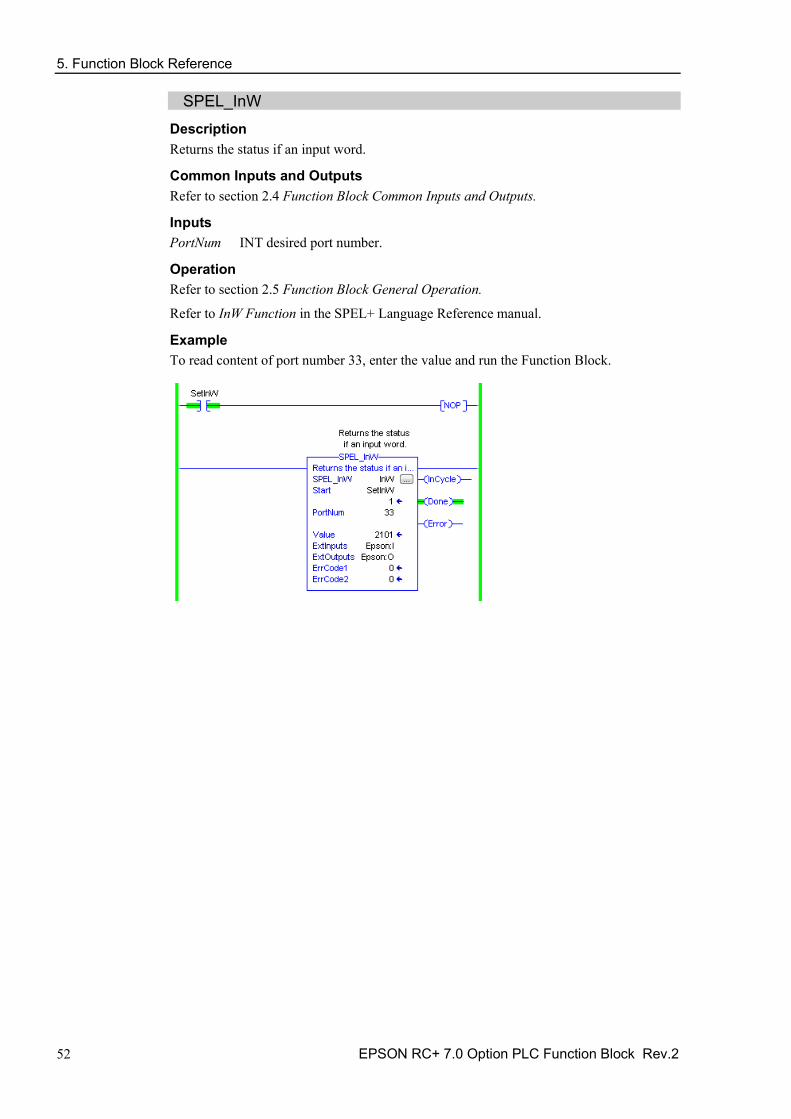
SPEL_InW Description Returns the status if an input word.
Common Inputs and Outputs Refer to section 2.4 Function Block Common Inputs and Outputs.
Inputs PortNum INT desired port number.
Operation Refer to section 2.5 Function Block General Operation.
Refer to InW Function in the SPEL+ Language Reference manual.
Example To read content of port number 33, enter the value and run the Function Block.

5. Function Block Reference
EPSON RC+ 7.0 Option PLC Function Block Rev.2 53
SPEL_Jog Description Jogs the robot.
Common Inputs and Outputs Refer to section 2.4 Function Block Common Inputs and Outputs.
Inputs JogMode INT desired mode. 0=World, 1=Joint. Axis INT desired axis. Distance REAL value:
World: X,Y,Z in mm. U,V,W in deg. Joint: J1-J6 in deg.
Operation Refer to section 2.5 Function Block General Operation.
Example To move robot in -Y direction for 40mm, enter values and run the Function Block as shown below.

5. Function Block Reference
54 EPSON RC+ 7.0 Option PLC Function Block Rev.2
SPEL_Jump Description Moves the arm using gate motion for a SCARA robot.
Common Inputs and Outputs Refer to section 2.4 Function Block Common Inputs and Outputs.
Inputs Point INT desired point.
Operation Refer to section 2.5 Function Block General Operation.
Refer to Jump Statement in the SPEL+ Language Reference manual.
Example To move the robot to point P2 using gate trajectory, enter the value for Point and run the Function Block as shown below.

5. Function Block Reference
EPSON RC+ 7.0 Option PLC Function Block Rev.2 55
SPEL_Jump3 Description Moves the arm with 3D gate motion for a 6-axis robot. This is a combination of two CP motion and one PTP motion.
Common Inputs and Outputs Refer to section 2.4 Function Block Common Inputs and Outputs.
Inputs DepartPoint INT desired depart point. ApproPoint INT desired approach point. DestPoint INT desired destination point.
Operation Refer to section 2.5 Function Block General Operation.
Refer to Jump3CP Statement in the SPEL+ Language Reference manual.
Example To move the robot to point P2 using gate trajectory, enter the values for the points and run the Function Block as shown below.

5. Function Block Reference
56 EPSON RC+ 7.0 Option PLC Function Block Rev.2
SPEL_Jump3CP Description Moves the arm with 3D gate motion for a 6-axis robot. This is a combination of three CP motions.
Common Inputs and Outputs Refer to section 2.4 Function Block Common Inputs and Outputs.
Inputs DepartPoint INT desired depart point. ApproPoint INT desired approach point. DestPoint INT desired destination point.
Operation Refer to section 2.5 Function Block General Operation.
Refer to Jump3CP Statement in the SPEL+ Language Reference manual.
Example To move the robot to point P2 using gate trajectory, enter the values for the points and run the Function Block as shown below.

5. Function Block Reference
EPSON RC+ 7.0 Option PLC Function Block Rev.2 57
SPEL_Lefty Description Sets the hand orientation of the specified point to Lefty.
Common Inputs and Outputs Refer to section 2.4 Function Block Common Inputs and Outputs.
Inputs Point INT desired point number.
Operation Refer to section 2.5 Function Block General Operation.
Refer to Hand Statement in the SPEL+ Language Reference manual.
Example To change P2’s hand orientation to Lefty, enter values and run the Function Block as shown below.

5. Function Block Reference
58 EPSON RC+ 7.0 Option PLC Function Block Rev.2
SPEL_LimZ Description Sets the initial Joint #3 height (Z coordinate value) in Jump command.
Common Inputs and Outputs Refer to section 2.4 Function Block Common Inputs and Outputs.
Inputs Height REAL desired Z limit in mm.
Operation Refer to section 2.5 Function Block General Operation.
Refer to LimZ Statement in the SPEL+ Language Reference manual.
Example To set LimZ value of 10mm, enter values and run the Function Block as shown below.

5. Function Block Reference
EPSON RC+ 7.0 Option PLC Function Block Rev.2 59
SPEL_LocalGet Description Gets data for a given local coordinate system.
Common Inputs and Outputs Refer to section 2.4 Function Block Common Inputs and Outputs.
Inputs NumAxes INT number of axes in the robot.
For SCARA, use 4, for Articulate robot, use 6. LocalNum INT desired local number you want to get.
Outputs LocalX REAL the coordinate value of that axis. LocalY REAL the coordinate value of that axis. LocalZ REAL the coordinate value of that axis. LocalU REAL the coordinate value of that axis. LocalV REAL the coordinate value of that axis. LocalW REAL the coordinate value of that axis.
Operation Refer to section 2.5 Function Block General Operation.
Refer to Local Statement in the SPEL+ Language Reference manual.
Example To get the coordinate values for local number 3 of a SCARA robot, enter values and run the Function Block as shown below.

5. Function Block Reference
60 EPSON RC+ 7.0 Option PLC Function Block Rev.2
SPEL_LocalSet Description Sets the local coordinate number.
Common Inputs and Outputs Refer to section 2.4 Function Block Common Inputs and Outputs.
Inputs NumAxes INT number of axes in the robot.
For SCARA, use 4, for Articulate robot, use 6. LocalNum INT desired local number you want to get. LocalX REAL the desired coordinate value of X axis. LocalY REAL the desired coordinate value of Y axis. LocalZ REAL the desired coordinate value of Z axis. LocalU REAL the desired coordinate value of U axis. LocalV REAL the desired coordinate value of V axis. LocalW REAL the desired coordinate value of W axis.
Operation Refer to section 2.5 Function Block General Operation.
Refer to Local Statement in the SPEL+ Language Reference manual.
Example To set the coordinate values for local number 3 of a SCARA robot, enter values and run the Function Block as shown below.

5. Function Block Reference
EPSON RC+ 7.0 Option PLC Function Block Rev.2 61
SPEL_MemIn Description Reads a byte of memory IO.
Common Inputs and Outputs Refer to section 2.4 Function Block Common Inputs and Outputs.
Inputs PortNum INT port number to be read. Port number refers to byte number.
Outputs Value INT value of the port.
Operation Refer to section 2.5 Function Block General Operation.
Refer to MemIn Function in the SPEL+ Language Reference manual.
Example To read port number 0 of memory I/O, run the Function Block as shown below.

5. Function Block Reference
62 EPSON RC+ 7.0 Option PLC Function Block Rev.2
SPEL_MemInW Description Reads a word of memory IO.
Common Inputs and Outputs Refer to section 2.4 Function Block Common Inputs and Outputs.
Inputs PortNum INT port number to be read.
Outputs Value INT value of the port.
Operation Refer to section 2.5 Function Block General Operation.
Refer to MemInW Function in the SPEL+ Language Reference manual.
Example To read port number 0 as word, run the Function Block as shown below.
5. Function Block Reference
EPSON RC+ 7.0 Option PLC Function Block Rev.2 63
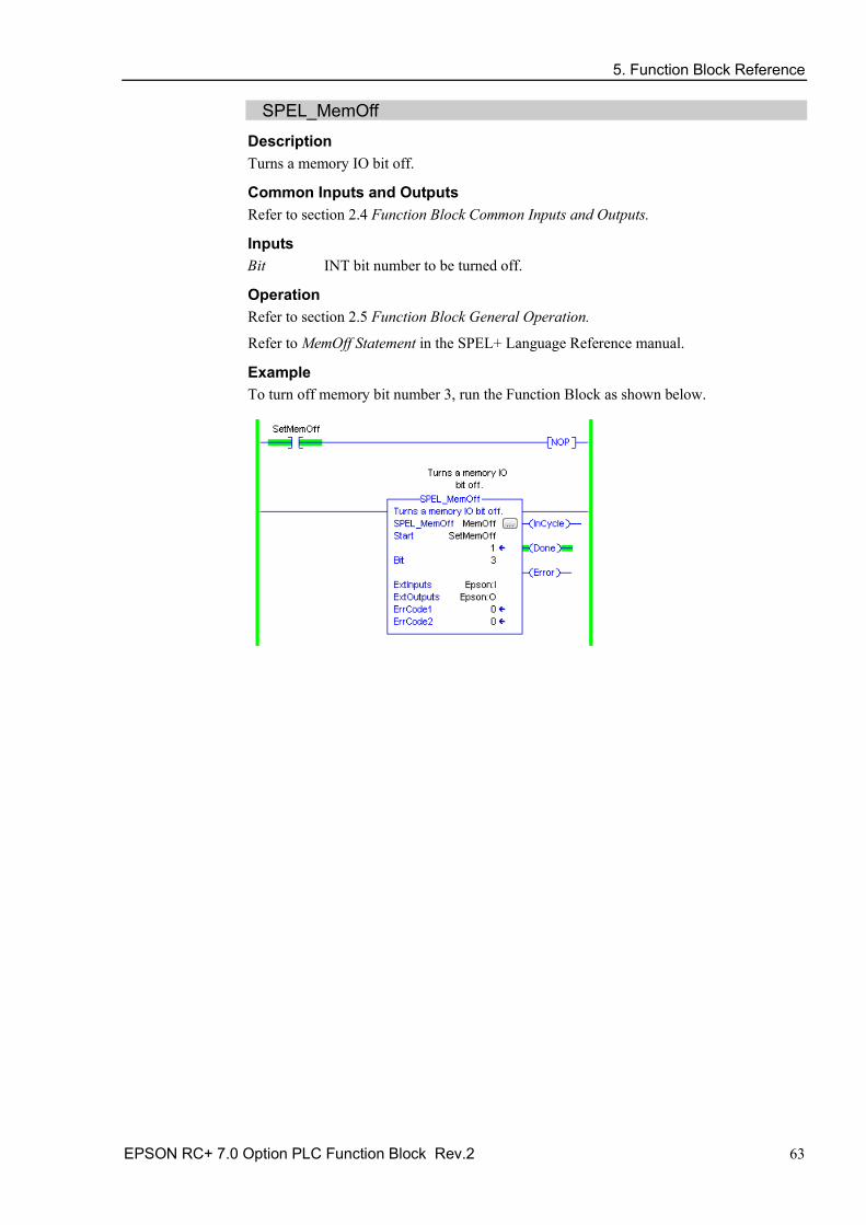
SPEL_MemOff Description Turns a memory IO bit off.
Common Inputs and Outputs Refer to section 2.4 Function Block Common Inputs and Outputs.
Inputs Bit INT bit number to be turned off.
Operation Refer to section 2.5 Function Block General Operation.
Refer to MemOff Statement in the SPEL+ Language Reference manual.
Example To turn off memory bit number 3, run the Function Block as shown below.

5. Function Block Reference
64 EPSON RC+ 7.0 Option PLC Function Block Rev.2
SPEL_MemOn Description Turns a memory IO bit on.
Common Inputs and Outputs Refer to section 2.4 Function Block Common Inputs and Outputs.
Inputs Bit INT bit number to be turned on.
Operation Refer to section 2.5 Function Block General Operation.
Refer to MemOn Statement in the SPEL+ Language Reference manual.
Example To turn on memory bit number 3, run the Function Block as shown below.

5. Function Block Reference
EPSON RC+ 7.0 Option PLC Function Block Rev.2 65
SPEL_MemOut Description Sets a byte of memory IO.
Common Inputs and Outputs Refer to section 2.4 Function Block Common Inputs and Outputs.
Inputs PortNum INT desired output port number. OutData INT value of the data to be sent to output port.
Operation Refer to section 2.5 Function Block General Operation.
Refer to MemOut Statement in the SPEL+ Language Reference manual.
Example To send 99 to port number 4, run the Function Block as shown below.
5. Function Block Reference
66 EPSON RC+ 7.0 Option PLC Function Block Rev.2
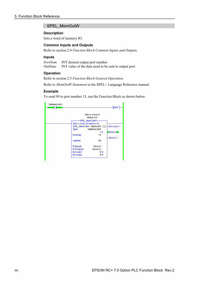
SPEL_MemOutW Description Sets a word of memory IO.
Common Inputs and Outputs Refer to section 2.4 Function Block Common Inputs and Outputs.
Inputs PortNum INT desired output port number. OutData INT value of the data need to be sent to output port.
Operation Refer to section 2.5 Function Block General Operation.
Refer to MemOutW Statement in the SPEL+ Language Reference manual.
Example To send 99 to port number 15, run the Function Block as shown below.

5. Function Block Reference
EPSON RC+ 7.0 Option PLC Function Block Rev.2 67
SPEL_MemSw Description Reads a single bit of memory IO.
Common Inputs and Outputs Refer to section 2.4 Function Block Common Inputs and Outputs.
Inputs Bit INT desired memory bit number.
Operation Refer to section 2.5 Function Block General Operation.
Refer to MemSw Function in the SPEL+ Language Reference manual.
Example To read memory bit number 5, run the Function Block as shown below.

5. Function Block Reference
68 EPSON RC+ 7.0 Option PLC Function Block Rev.2
SPEL_MotorOff Description Turns robot motors off.
Common Inputs and Outputs Refer to section 2.4 Function Block Common Inputs and Outputs.
Operation Refer to section 2.5 Function Block General Operation.
Refer to Motor Statement in the SPEL+ Language Reference manual.
Example To turn off motors, run the Function Block as shown below.

5. Function Block Reference
EPSON RC+ 7.0 Option PLC Function Block Rev.2 69
SPEL_MotorOn Description Turns robot motors on.
Common Inputs and Outputs Refer to section 2.4 Function Block Common Inputs and Outputs.
Operation Refer to section 2.5 Function Block General Operation.
Refer to Motor Statement in the SPEL+ Language Reference manual.
Example To turn on motors, run the Function Block as shown below.
5. Function Block Reference
70 EPSON RC+ 7.0 Option PLC Function Block Rev.2
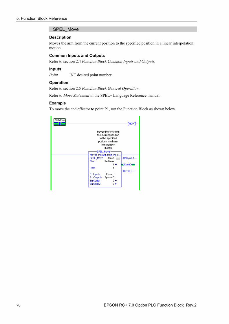
SPEL_Move Description Moves the arm from the current position to the specified position in a linear interpolation motion.
Common Inputs and Outputs Refer to section 2.4 Function Block Common Inputs and Outputs.
Inputs Point INT desired point number.
Operation Refer to section 2.5 Function Block General Operation.
Refer to Move Statement in the SPEL+ Language Reference manual.
Example To move the end effector to point P1, run the Function Block as shown below.

5. Function Block Reference
EPSON RC+ 7.0 Option PLC Function Block Rev.2 71
SPEL_NoFlip Description Sets the wrist orientation of the specified point to NOFLIP.
Common Inputs and Outputs Refer to section 2.4 Function Block Common Inputs and Outputs.
Inputs Point INT desired point number.
Operation Refer to section 2.5 Function Block General Operation.
Refer to Wrist Statement in the SPEL+ Language Reference manual
Example To set point P2 orientation to NoFlip, run the Function Block as shown below.
5. Function Block Reference
72 EPSON RC+ 7.0 Option PLC Function Block Rev.2
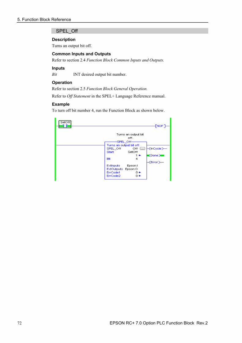
SPEL_Off Description Turns an output bit off.
Common Inputs and Outputs Refer to section 2.4 Function Block Common Inputs and Outputs.
Inputs Bit INT desired output bit number.
Operation Refer to section 2.5 Function Block General Operation.
Refer to Off Statement in the SPEL+ Language Reference manual.
Example To turn off bit number 4, run the Function Block as shown below.

5. Function Block Reference
EPSON RC+ 7.0 Option PLC Function Block Rev.2 73
SPEL_On Description Turns an output bit on.
Common Inputs and Outputs Refer to section 2.4 Function Block Common Inputs and Outputs.
Inputs Bit INT desired output bit number.
Operation Refer to section 2.5 Function Block General Operation.
Refer to On Statement in the SPEL+ Language Reference manual.
Example To turn on bit number 4, run the Function Block as shown below.
5. Function Block Reference
74 EPSON RC+ 7.0 Option PLC Function Block Rev.2
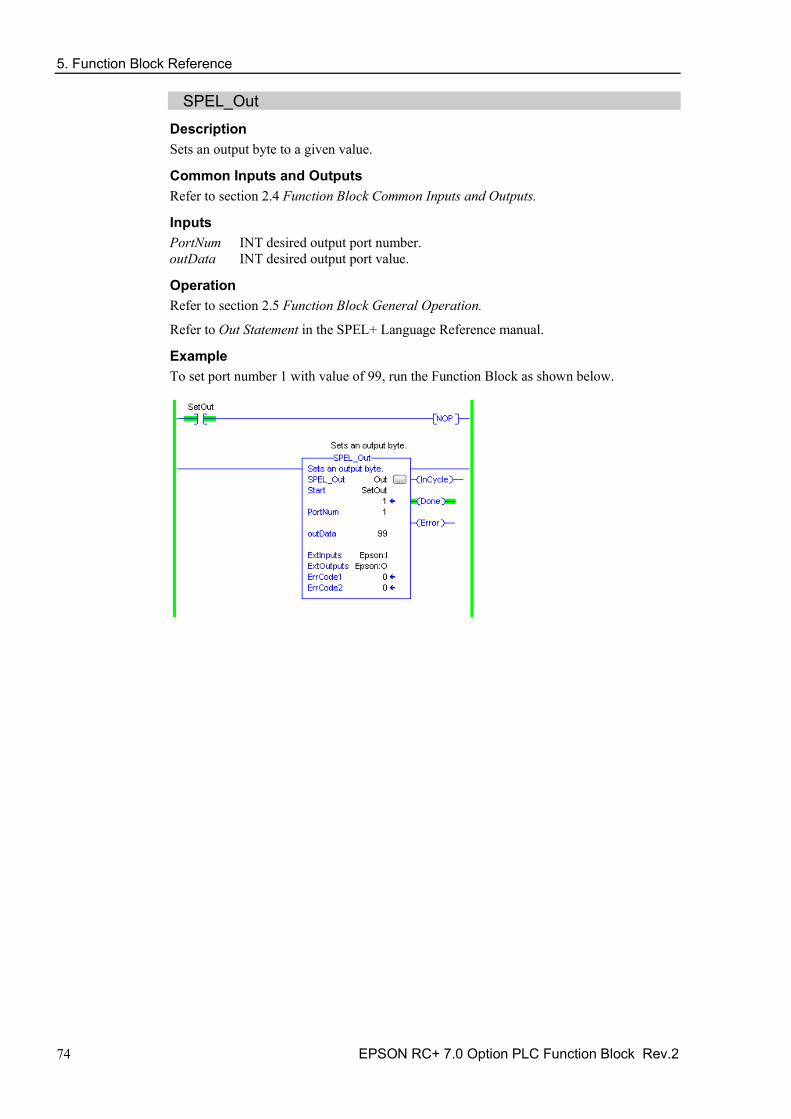
SPEL_Out Description Sets an output byte to a given value.
Common Inputs and Outputs Refer to section 2.4 Function Block Common Inputs and Outputs.
Inputs PortNum INT desired output port number. outData INT desired output port value.
Operation Refer to section 2.5 Function Block General Operation.
Refer to Out Statement in the SPEL+ Language Reference manual.
Example To set port number 1 with value of 99, run the Function Block as shown below.

5. Function Block Reference
EPSON RC+ 7.0 Option PLC Function Block Rev.2 75
SPEL_OutW Description Sets an output word to a given value.
Common Inputs and Outputs Refer to section 2.4 Function Block Common Inputs and Outputs.
Inputs PortNum INT desired output port number. outData INT desired output port value.
Operation Refer to section 2.5 Function Block General Operation.
Refer to OutWStatement in the SPEL+ Language Reference manual.
Example To set port number 0 with value of 99, run the Function Block as shown below.

5. Function Block Reference
76 EPSON RC+ 7.0 Option PLC Function Block Rev.2
SPEL_PowerHigh Description Sets the power level of robot to high.
Common Inputs and Outputs Refer to section 2.4 Function Block Common Inputs and Outputs.
Operation Refer to section 2.5 Function Block General Operation.
Refer to Power Statement in the SPEL+ Language Reference manual.
Example To set power high to the robot, run the Function Block as shown below.
5. Function Block Reference
EPSON RC+ 7.0 Option PLC Function Block Rev.2 77
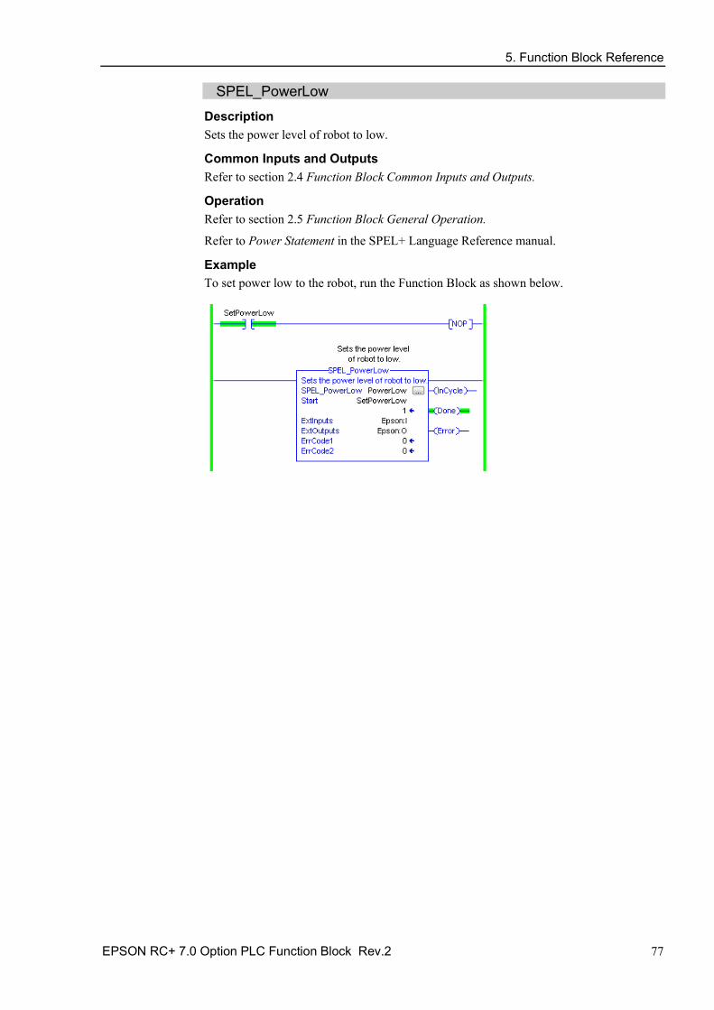
SPEL_PowerLow Description Sets the power level of robot to low.
Common Inputs and Outputs Refer to section 2.4 Function Block Common Inputs and Outputs.
Operation Refer to section 2.5 Function Block General Operation.
Refer to Power Statement in the SPEL+ Language Reference manual.
Example To set power low to the robot, run the Function Block as shown below.

5. Function Block Reference
78 EPSON RC+ 7.0 Option PLC Function Block Rev.2
SPEL_ResetError Description Reset the robot controller Function Block error state. After an error has occurred while executing a Function Block, you must execute SPEL_ResetError successfully before you can execute another Function Block.
Note: If the controller has a system error, then it must be reset before SPEL_Init and other Function Blocks can execute successfully.
Common Inputs and Outputs Refer to section 2.4 Function Block Common Inputs and Outputs.

5. Function Block Reference
EPSON RC+ 7.0 Option PLC Function Block Rev.2 79
SPEL_Righty Description Sets the hand orientation of the specified point to Righty.
Common Inputs and Outputs Refer to section 2.4 Function Block Common Inputs and Outputs.
Inputs Point INT desired point.
Operation Refer to section 2.5 Function Block General Operation.
Refer to Hand Statement in the SPEL+ Language Reference manual
Example To set orientation of P2 to Righty, run the Function Block as shown below.

5. Function Block Reference
80 EPSON RC+ 7.0 Option PLC Function Block Rev.2
SPEL_SavePoints Description Saves the current point data in robot controller memory to the default point file for robot 1 (robot1.pts) in the robot controller. To use this command, a valid RC+ project must exist in the controller. Typically, SavePoints is used to save points taught using the SPEL_Teach Function Block. When the controller starts up, it loads the project and the default point file, so the saved points are in memory.
Do not use a point file except for robot1.pts.
Common Inputs and Outputs Refer to section 2.4 Function Block Common Inputs and Outputs.
Operation Refer to section 2.5 Function Block General Operation.
Refer to SavePoints Statement in the SPEL+ Language Reference manual
Example To save all points in robot controller memory to the file robot1.pts in the robot controller, run the Function Block as shown below.

5. Function Block Reference
EPSON RC+ 7.0 Option PLC Function Block Rev.2 81
SPEL_Speed Description Sets the arm speed setting for PTP motion.
Common Inputs and Outputs Refer to section 2.4 Function Block Common Inputs and Outputs.
Inputs Speed INT desired speed. ApproSpeed INT desired approach speed, units are %. DepartSpeed INT desired depart speed, units are %.
Operation Refer to section 2.5 Function Block General Operation.
Refer to Speed Statement in the SPEL+ Language Reference manual.
Example To set Speed to 100%, Approach, Depart Speed to 50%, run the Function Block as shown below.

5. Function Block Reference
82 EPSON RC+ 7.0 Option PLC Function Block Rev.2
SPEL_SpeedS Description Sets the arm speed setting of CP motion. This will set the depart, and approach speed as well.
Common Inputs and Outputs Refer to section 2.4 Function Block Common Inputs and Outputs.
Inputs Speed INT desired speed. ApproSpeed INT desired approach speed. DepartSpeed INT desired depart speed.
Operation Refer to section 2.5 Function Block General Operation.
Refer to SpeedS Statement in the SPEL+ Language Reference manual.
Example To set Speed to 100, Approach, Depart Speed to 40, run the Function Block as shown below.

5. Function Block Reference
EPSON RC+ 7.0 Option PLC Function Block Rev.2 83
SPEL_Sw Description Reads the status of an input bit.
Common Inputs and Outputs Refer to section 2.4 Function Block Common Inputs and Outputs.
Inputs Bit INT desired input bit.
Outputs Value INT the value of the input bit.
Operation Refer to section 2.5 Function Block General Operation.
Refer to Sw Function in the SPEL+ Language Reference manual.
Example To read the value of input bit number 514, run the Function Block as shown below.

5. Function Block Reference
84 EPSON RC+ 7.0 Option PLC Function Block Rev.2
SPEL_Teach Description Teaches specified robot point in the robot controller to the current robot position.
Common Inputs and Outputs Refer to section 2.4 Function Block Common Inputs and Outputs.
Inputs Point INT desired point.
Operation Refer to section 2.5 Function Block General Operation.
Refer to Here Statement in the SPEL+ Language Reference manual.
Example To teach current robot position for robot point P5, run the Function Block as shown below.

5. Function Block Reference
EPSON RC+ 7.0 Option PLC Function Block Rev.2 85
SPEL_ToolGet Description Gets the tool selection status.
Common Inputs and Outputs Refer to section 2.4 Function Block Common Inputs and Outputs.
Outputs ToolNum INT the tool selected.
Operation Refer to section 2.5 Function Block General Operation.
Refer to Tool Function in the SPEL+ Language Reference manual.
Example To read the selected tool by the robot, run the Function Block as shown below.

5. Function Block Reference
86 EPSON RC+ 7.0 Option PLC Function Block Rev.2
SPEL_ToolSet Description Sets the tool.
Common Inputs and Outputs Refer to section 2.4 Function Block Common Inputs and Outputs.
Inputs ToolNum INT the tool to be set.
Operation Refer to section 2.5 Function Block General Operation.
Refer to Tool Statement in the SPEL+ Language Reference manual.
Example To set current tool to 3, run the Function Block as shown below.

5. Function Block Reference
EPSON RC+ 7.0 Option PLC Function Block Rev.2 87
SPEL_WeightGet Description Gets the hand weight and arm length parameters.
Common Inputs and Outputs Refer to section 2.4 Function Block Common Inputs and Outputs.
Inputs HandWeight REAL weight of the hand. ArmLength REAL length of the arm.
Operation Refer to section 2.5 Function Block General Operation.
Refer to Weight Function in the SPEL+ Language Reference manual.
Example To get the current hand weight and arm length, run the Function Block as shown below.

5. Function Block Reference
88 EPSON RC+ 7.0 Option PLC Function Block Rev.2
SPEL_WeightSet Description Sets the weight parameter.
Common Inputs and Outputs Refer to section 2.4 Function Block Common Inputs and Outputs.
Inputs HandWeight REAL weight of the hand. ArmLength REAL length of the arm.
Operation Refer to section 2.5 Function Block General Operation.
Refer to Wait Statement in the SPEL+ Language Reference manual.
Example To set the hand weight and arm length, run the Function Block as shown below.
5. Function Block Reference
EPSON RC+ 7.0 Option PLC Function Block Rev.2 89
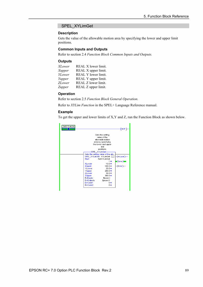
SPEL_XYLimGet Description Gets the value of the allowable motion area by specifying the lower and upper limit positions.
Common Inputs and Outputs Refer to section 2.4 Function Block Common Inputs and Outputs.
Outputs XLower REAL X lower limit. Xupper REAL X upper limit. YLower REAL Y lower limit. Yupper REAL Y upper limit. ZLower REAL Z lower limit. Zupper REAL Z upper limit.
Operation Refer to section 2.5 Function Block General Operation.
Refer to XYLim Function in the SPEL+ Language Reference manual.
Example To get the upper and lower limits of X,Y and Z, run the Function Block as shown below.
5. Function Block Reference
90 EPSON RC+ 7.0 Option PLC Function Block Rev.2
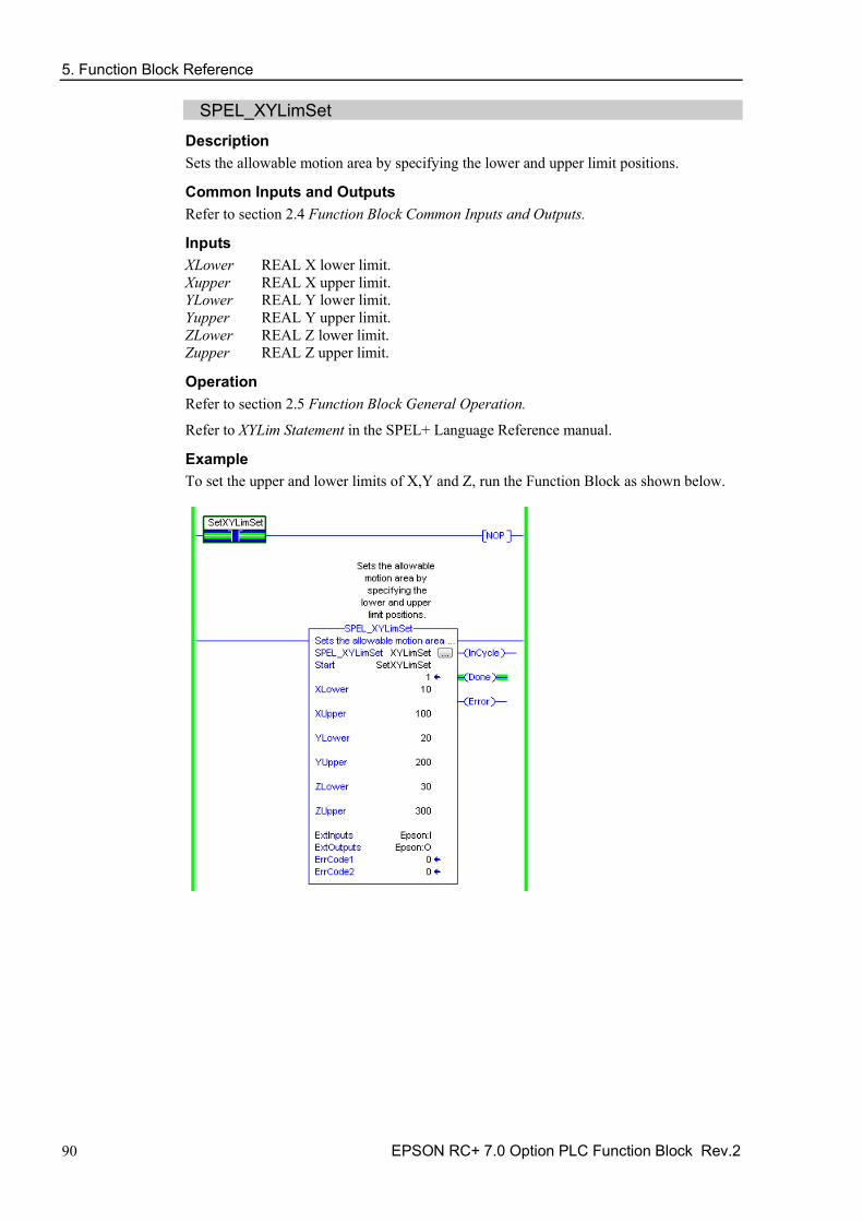
SPEL_XYLimSet Description Sets the allowable motion area by specifying the lower and upper limit positions.
Common Inputs and Outputs Refer to section 2.4 Function Block Common Inputs and Outputs.
Inputs XLower REAL X lower limit. Xupper REAL X upper limit. YLower REAL Y lower limit. Yupper REAL Y upper limit. ZLower REAL Z lower limit. Zupper REAL Z upper limit.
Operation Refer to section 2.5 Function Block General Operation.
Refer to XYLim Statement in the SPEL+ Language Reference manual.
Example To set the upper and lower limits of X,Y and Z, run the Function Block as shown below.
5. Function Block Reference
EPSON RC+ 7.0 Option PLC Function Block Rev.2 91
5.2 Function Block for CODESYS
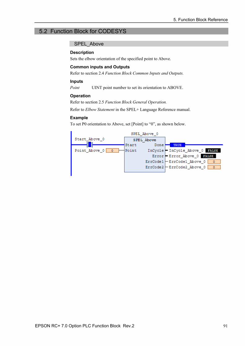
SPEL_Above Description Sets the elbow orientation of the specified point to Above.
Common inputs and Outputs Refer to section 2.4 Function Block Common Inputs and Outputs.
Inputs Point UINT point number to set its orientation to ABOVE.
Operation Refer to section 2.5 Function Block General Operation.
Refer to Elbow Statement in the SPEL+ Language Reference manual.
Example To set P0 orientation to Above, set [Point] to “0”, as shown below.

5. Function Block Reference
92 EPSON RC+ 7.0 Option PLC Function Block Rev.2
SPEL_Accel Description Sets the point to point acceleration and deceleration. Specifies the ratio (%) of the maximum acceleration/deceleration using an integer equals to or greater than 1.
Common inputs and Outputs Refer to section 2.4 Function Block Common Inputs and Outputs.
Inputs Accel UINT value of acceleration as percentage. Decel UINT value of deceleration as percentage.
Operation Refer to section 2.5 Function Block General Operation.
Refer to Accel Statement in the SPEL+ Language Reference manual.
Example To set acceleration to 50% and deceleration to 50%, set [Accel] to “50” and [Decel] to “50”, as shown below.

5. Function Block Reference
EPSON RC+ 7.0 Option PLC Function Block Rev.2 93
SPEL_AccelS Description Sets acceleration and deceleration. Specifies the value which is the actual acceleration/deceleration in linear or CP motion (Unit: mm/sec2).
Common Inputs and Outputs Refer to section 2.4 Function Block Common Inputs and Outputs.
Inputs Accel REAL value of acceleration. Decel REAL value of deceleration.
Operation Refer to section 2.5 Function Block General Operation.
Refer to AccelS Statement in the SPEL+ Language Reference manual.
Example To set acceleration to 100.200, deceleration to 200.100, set [Accel] to “100.200”, [Decel] to “200.100”, as shown below.

5. Function Block Reference
94 EPSON RC+ 7.0 Option PLC Function Block Rev.2
SPEL_Arc Description Moves the arm from the current position to the specified position in circular interpolation motion on XY plane face.
Common Inputs and Outputs Refer to section 2.4 Function Block Common Inputs and Outputs.
Inputs midPoint UINT middle point in Arc command. endPoint UINT end point in Arc command. MaxTime DINT Function Block execution is timeout.
Operation Refer to section 2.5 Function Block General Operation.
Refer to Arc Statement in the SPEL+ Language Reference manual.
Example To move from current position passing through P2 and ending at P3, in a circular motion.

5. Function Block Reference
EPSON RC+ 7.0 Option PLC Function Block Rev.2 95
SPEL_Arc3 Description Moves the arm from the current position to the specified position in circular interpolation in 3 dimensions.
Common Inputs and Outputs Refer to section 2.4 Function Block Common Inputs and Outputs.
Inputs midPoint UINT middle point in Arc3 command. endPoint UINT end point in Arc3 command. MaxTime DINT Function Block execution is timeout.
Operation Refer to section 2.5 Function Block General Operation.
Refer to Arc3 Statement in the SPEL+ Language Reference manual.
Example To move from current position passing through P1 and ending at P2, in a circular motion.

5. Function Block Reference
96 EPSON RC+ 7.0 Option PLC Function Block Rev.2
SPEL_ArchGet Description Gets the Arch parameter.
Common Inputs and Outputs Refer to section 2.4 Function Block Common Inputs and Outputs.
Inputs ArchNum UINT desired Arch number.
Outputs DepartDist REAL departing distance of the given Arch number. ApproachDist REAL approaching distance of the given Arch number.
Operation Refer to section 2.5 Function Block General Operation.
Refer to Arch Function in the SPEL+ Language Reference manual.
Example To get the current values of approach and depart distances of given Arch, set the Arch number.

5. Function Block Reference
EPSON RC+ 7.0 Option PLC Function Block Rev.2 97
SPEL_ArchSet Description Sets the Arch parameter.
Common Inputs and Outputs Refer to section 2.4 Function Block Common Inputs and Outputs.
Inputs ArchNum UINT desired Arch number. DepartDist REAL departing distance of the given Arch number. ApproachDist REAL approaching distance of the given Arch number.
Operation Refer to section 2.5 Function Block General Operation.
Refer to Arch Statement in the SPEL+ Language Reference manual.
Example To set 60.0, 60.0 as depart and approach distances respectively of Arch 2, see below.
5. Function Block Reference
98 EPSON RC+ 7.0 Option PLC Function Block Rev.2
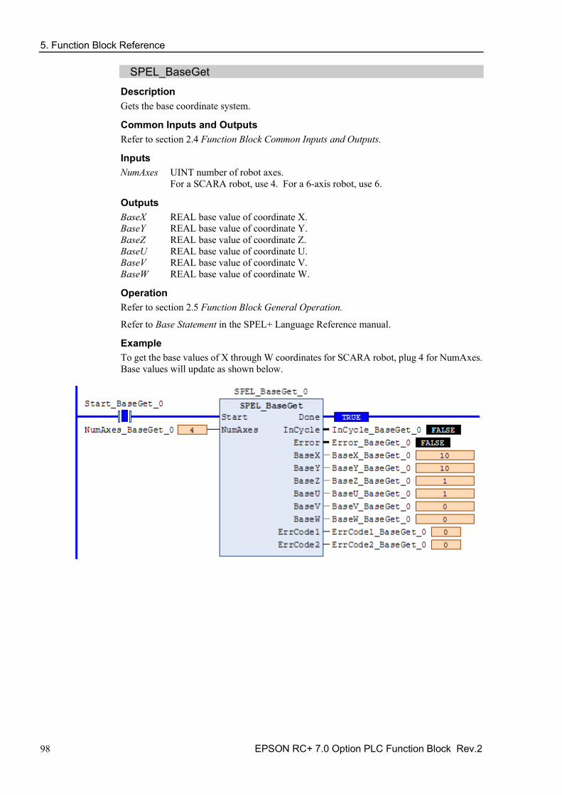
SPEL_BaseGet Description Gets the base coordinate system.
Common Inputs and Outputs Refer to section 2.4 Function Block Common Inputs and Outputs.
Inputs NumAxes UINT number of robot axes.
For a SCARA robot, use 4. For a 6-axis robot, use 6.
Outputs BaseX REAL base value of coordinate X. BaseY REAL base value of coordinate Y. BaseZ REAL base value of coordinate Z. BaseU REAL base value of coordinate U. BaseV REAL base value of coordinate V. BaseW REAL base value of coordinate W.
Operation Refer to section 2.5 Function Block General Operation.
Refer to Base Statement in the SPEL+ Language Reference manual.
Example To get the base values of X through W coordinates for SCARA robot, plug 4 for NumAxes. Base values will update as shown below.

5. Function Block Reference
EPSON RC+ 7.0 Option PLC Function Block Rev.2 99
SPEL_BaseSet Description Sets the base coordinate system.
Common Inputs and Outputs Refer to section 2.4 Function Block Common Inputs and Outputs.
Inputs NumAxes UINT number of robot axes.
For a SCARA robot, use 4. For a 6-axis robot, use 6. BaseX REAL base value of coordinate X. BaseY REAL base value of coordinate Y. BaseZ REAL base value of coordinate Z. BaseU REAL base value of coordinate U. BaseV REAL base value of coordinate V. BaseW REAL base value of coordinate W.
Operation Refer to section 2.5 Function Block General Operation.
Refer to Base Statement in the SPEL+ Language Reference manual.
Example To set the base value of a SCARA robot, set NumAxes = 4. Enter the base coordinate value for each axis, as shown below.

5. Function Block Reference
100 EPSON RC+ 7.0 Option PLC Function Block Rev.2
SPEL_Below Description Sets the elbow orientation of the specified point to Below.
Common Inputs and Outputs Refer to section 2.4 Function Block Common Inputs and Outputs.
Inputs Point UINT desired point number.
Operation Refer to section 2.5 Function Block General Operation.
Refer to Elbow Statement in the SPEL+ Language Reference manual.
Example To set orientation of P2 to below, enter 2 as point. As shown below.
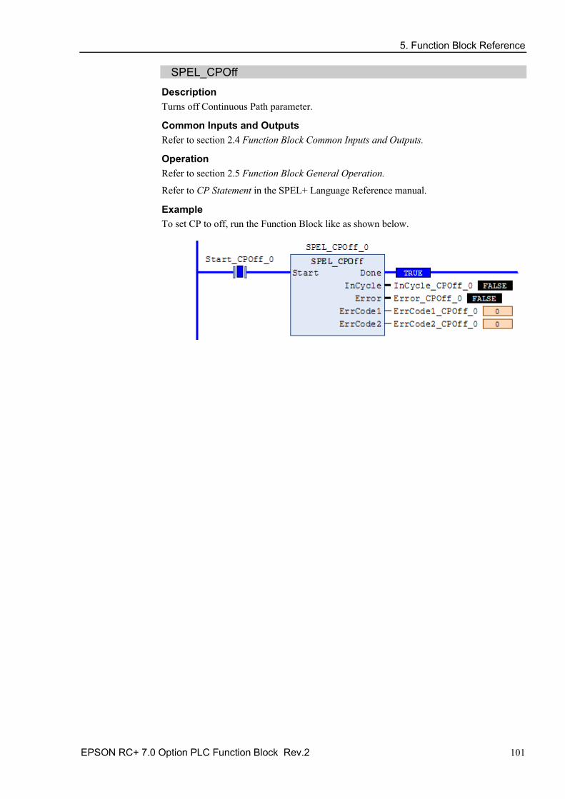
5. Function Block Reference
EPSON RC+ 7.0 Option PLC Function Block Rev.2 101
SPEL_CPOff Description Turns off Continuous Path parameter.
Common Inputs and Outputs Refer to section 2.4 Function Block Common Inputs and Outputs.
Operation Refer to section 2.5 Function Block General Operation.
Refer to CP Statement in the SPEL+ Language Reference manual.
Example To set CP to off, run the Function Block like as shown below.

5. Function Block Reference
102 EPSON RC+ 7.0 Option PLC Function Block Rev.2
SPEL_CPOn Description Turns on Continuous Path parameter.
Common Inputs and Outputs Refer to section 2.4 Function Block Common Inputs and Outputs.
Operation Refer to section 2.5 Function Block General Operation.
Refer to CP Statement in the SPEL+ Language Reference manual.
Example To set CP to On, run the Function Block as shown below.

5. Function Block Reference
EPSON RC+ 7.0 Option PLC Function Block Rev.2 103
SPEL_ExecCmd Description The SPEL_ExecCmd Function Block is used by other Function Blocks to execute a command in the robot controller.

5. Function Block Reference
104 EPSON RC+ 7.0 Option PLC Function Block Rev.2
SPEL_FineGet Description Gets the setting of positioning end judgement range for all joints.
Outputs Axis1..Axis6 UINT position accuracy for each joint in encoder pulses.
Operation Refer to section 2.5 Function Block General Operation.
Refer to Fine Function in the SPEL+ Language Reference manual.
Example To get the position accuracy for the robot, run the Function Block as shown below.

5. Function Block Reference
EPSON RC+ 7.0 Option PLC Function Block Rev.2 105
SPEL_FineSet Description Sets the positioning end judgement range for all joints.
Common Inputs and Outputs Refer to section 2.4 Function Block Common Inputs and Outputs.
Inputs Axis1..Axis6 UINT position accuracy for each joint in encoder pulses.
Operation Refer to section 2.5 Function Block General Operation.
Refer to Fine Statement in the SPEL+ Language Reference manual.
Example To set the position accuracy for the robot, enter the Axis values and run the Function Block as shown below.

5. Function Block Reference
106 EPSON RC+ 7.0 Option PLC Function Block Rev.2
SPEL_Flip Description Sets the wrist orientation of the specified point to Flip.
Common Inputs and Outputs Refer to section 2.4 Function Block Common Inputs and Outputs.
Inputs Point UINT desired point number.
Operation Refer to section 2.5 Function Block General Operation.
Refer to Wrist Statement in the SPEL+ Language Reference manual.
Example To set orientation of robot point P2 to flip, enter 2 as the point number and run the Function Block as shown below.

5. Function Block Reference
EPSON RC+ 7.0 Option PLC Function Block Rev.2 107
SPEL_Go Description Moves from the current position to the specified position in PTP motion.
Common Inputs and Outputs Refer to section 2.4 Function Block Common Inputs and Outputs.
Inputs Point UINT desired point number. MaxTime DINT Function Block execution is timeout.
Operation Refer to section 2.5 Function Block General Operation.
Refer to Go Statement in the SPEL+ Language Reference manual.
Example To move the robot to point 0 using PTP motion, enter “0” as the point and run the Function Block, as shown below.

5. Function Block Reference
108 EPSON RC+ 7.0 Option PLC Function Block Rev.2
SPEL_In Description Reads a byte of input.
Common Inputs and Outputs Refer to section 2.4 Function Block Common Inputs and Outputs.
Inputs PortNum UINT desired input byte port number.
Outputs Value BYTE value of the desired input port.
Operation Refer to section 2.5 Function Block General Operation.
Refer to In Function in the SPEL+ Language Reference manual.
Example To read input port number 66, set [PortNum] to “66”.

5. Function Block Reference
EPSON RC+ 7.0 Option PLC Function Block Rev.2 109
SPEL_InertiaGet Description Gets the load inertia.
Common Inputs and Outputs Refer to section 2.4 Function Block Common Inputs and Outputs.
Outputs Inertia REAL acquired Inertia. Eccentricity REAL acquired Eccentricity.
Operation Refer to section 2.5 Function Block General Operation.
Refer to Inertia Function in the SPEL+ Language Reference manual.
Example To read load Inertia and Eccentricity, run the Function Block, as shown below.

5. Function Block Reference
110 EPSON RC+ 7.0 Option PLC Function Block Rev.2
SPEL_InertiaSet Description Sets the load inertia.
Common Inputs and Outputs Refer to section 2.4 Function Block Common Inputs and Outputs.
Inputs Inertia REAL desired Inertia. Eccentricity REAL desired Eccentricity.
Operation Refer to section 2.5 Function Block General Operation.
Refer to Inertia Statement in the SPEL+ Language Reference manual.
Example To set load Inertia and Eccentricity to 0.01, 0.01 respectively, enter the values and run the Function Block.
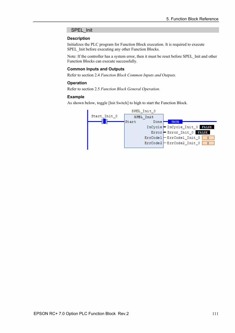
5. Function Block Reference
EPSON RC+ 7.0 Option PLC Function Block Rev.2 111
SPEL_Init Description Initializes the PLC program for Function Block execution. It is required to execute SPEL_Init before executing any other Function Blocks.
Note: If the controller has a system error, then it must be reset before SPEL_Init and other Function Blocks can execute successfully.
Common Inputs and Outputs Refer to section 2.4 Function Block Common Inputs and Outputs.
Operation Refer to section 2.5 Function Block General Operation.
Example As shown below, toggle [Init Switch] to high to start the Function Block.
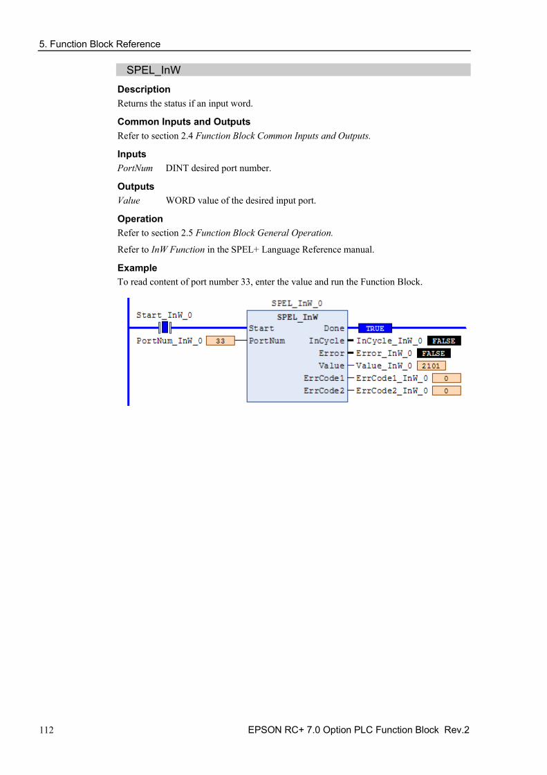
5. Function Block Reference
112 EPSON RC+ 7.0 Option PLC Function Block Rev.2
SPEL_InW Description Returns the status if an input word.
Common Inputs and Outputs Refer to section 2.4 Function Block Common Inputs and Outputs.
Inputs PortNum DINT desired port number.
Outputs Value WORD value of the desired input port.
Operation Refer to section 2.5 Function Block General Operation.
Refer to InW Function in the SPEL+ Language Reference manual.
Example To read content of port number 33, enter the value and run the Function Block.

5. Function Block Reference
EPSON RC+ 7.0 Option PLC Function Block Rev.2 113
SPEL_Jog Description Jogs the robot.
Common Inputs and Outputs Refer to section 2.4 Function Block Common Inputs and Outputs.
Inputs JogMode UINT desired mode. 0=World, 1=Joint. Axis UINT desired axis. Distance REAL value:
World: X,Y,Z in mm. U,V,W in deg. Joint: J1-J6 in deg.
MaxTime DINT Function Block execution is timeout.
Operation Refer to section 2.5 Function Block General Operation.
Example To move robot in -Y direction for 40mm, enter values and run the Function Block as shown below.
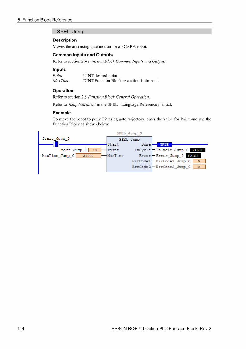
5. Function Block Reference
114 EPSON RC+ 7.0 Option PLC Function Block Rev.2
SPEL_Jump Description Moves the arm using gate motion for a SCARA robot.
Common Inputs and Outputs Refer to section 2.4 Function Block Common Inputs and Outputs.
Inputs Point UINT desired point. MaxTime DINT Function Block execution is timeout.
Operation Refer to section 2.5 Function Block General Operation.
Refer to Jump Statement in the SPEL+ Language Reference manual.
Example To move the robot to point P2 using gate trajectory, enter the value for Point and run the Function Block as shown below.

5. Function Block Reference
EPSON RC+ 7.0 Option PLC Function Block Rev.2 115
SPEL_Jump3 Description Moves the arm with 3D gate motion for a 6-axis robot. This is a combination of two CP motion and one PTP motion.
Common Inputs and Outputs Refer to section 2.4 Function Block Common Inputs and Outputs.
Inputs DepartPoint UINT desired depart point. ApproPoint UINT desired approach point. DestPoint UINT desired destination point. MaxTime DINT Function Block execution is timeout.
Operation Refer to section 2.5 Function Block General Operation.
Refer to Jump3CP Statement in the SPEL+ Language Reference manual.
Example To move the robot to point P2 using gate trajectory, enter the values for the points and run the Function Block as shown below.

5. Function Block Reference
116 EPSON RC+ 7.0 Option PLC Function Block Rev.2
SPEL_Jump3CP Description Moves the arm with 3D gate motion for a 6-axis robot. This is a combination of three CP motions.
Common Inputs and Outputs Refer to section 2.4 Function Block Common Inputs and Outputs.
Inputs DepartPoint UINT desired depart point. ApproPoint UINT desired approach point. DestPoint UINT desired destination point. MaxTime DINT Function Block execution is timeout.
Operation Refer to section 2.5 Function Block General Operation.
Refer to Jump3CP Statement in the SPEL+ Language Reference manual.
Example To move the robot to point P2 using gate trajectory, enter the values for the points and run the Function Block as shown below.

5. Function Block Reference
EPSON RC+ 7.0 Option PLC Function Block Rev.2 117
SPEL_Lefty Description Sets the hand orientation of the specified point to Lefty.
Common Inputs and Outputs Refer to section 2.4 Function Block Common Inputs and Outputs.
Inputs Point UINT desired point number.
Operation Refer to section 2.5 Function Block General Operation.
Refer to Hand Statement in the SPEL+ Language Reference manual.
Example To change P2’s hand orientation to Lefty, enter values and run the Function Block as shown below.

5. Function Block Reference
118 EPSON RC+ 7.0 Option PLC Function Block Rev.2
SPEL_LimZ Description Sets the initial Joint #3 height (Z coordinate value) in Jump command.
Common Inputs and Outputs Refer to section 2.4 Function Block Common Inputs and Outputs.
Inputs Height REAL desired Z limit in mm.
Operation Refer to section 2.5 Function Block General Operation.
Refer to LimZ Statement in the SPEL+ Language Reference manual.
Example To set LimZ value of 10mm, enter values and run the Function Block as shown below.

5. Function Block Reference
EPSON RC+ 7.0 Option PLC Function Block Rev.2 119
SPEL_LocalGet Description Gets data for a given local coordinate system.
Common Inputs and Outputs Refer to section 2.4 Function Block Common Inputs and Outputs.
Inputs NumAxes UINT number of axes in the robot.
For SCARA, use 4, for Articulate robot, use 6. LocalNum UINT desired local number you want to get.
Outputs LocalX REAL the coordinate value of that axis. LocalY REAL the coordinate value of that axis. LocalZ REAL the coordinate value of that axis. LocalU REAL the coordinate value of that axis. LocalV REAL the coordinate value of that axis. LocalW REAL the coordinate value of that axis.
Operation Refer to section 2.5 Function Block General Operation.
Refer to Local Statement in the SPEL+ Language Reference manual.
Example To get the coordinate values for local number 3 of a SCARA robot, enter values and run the Function Block as shown below.
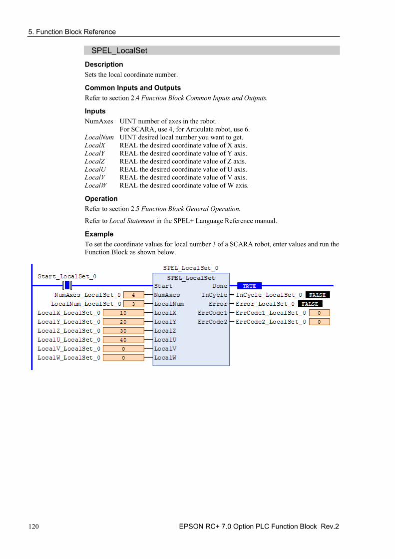
5. Function Block Reference
120 EPSON RC+ 7.0 Option PLC Function Block Rev.2
SPEL_LocalSet Description Sets the local coordinate number.
Common Inputs and Outputs Refer to section 2.4 Function Block Common Inputs and Outputs.
Inputs NumAxes UINT number of axes in the robot.
For SCARA, use 4, for Articulate robot, use 6. LocalNum UINT desired local number you want to get. LocalX REAL the desired coordinate value of X axis. LocalY REAL the desired coordinate value of Y axis. LocalZ REAL the desired coordinate value of Z axis. LocalU REAL the desired coordinate value of U axis. LocalV REAL the desired coordinate value of V axis. LocalW REAL the desired coordinate value of W axis.
Operation Refer to section 2.5 Function Block General Operation.
Refer to Local Statement in the SPEL+ Language Reference manual.
Example To set the coordinate values for local number 3 of a SCARA robot, enter values and run the Function Block as shown below.

5. Function Block Reference
EPSON RC+ 7.0 Option PLC Function Block Rev.2 121
SPEL_MemIn Description Reads a byte of memory IO.
Common Inputs and Outputs Refer to section 2.4 Function Block Common Inputs and Outputs.
Inputs PortNum UINT port number to be read. Port number refers to byte number.
Outputs Value BYTE value of the port.
Operation Refer to section 2.5 Function Block General Operation.
Refer to MemIn Function in the SPEL+ Language Reference manual.
Example To read port number 0 of memory I/O, run the Function Block as shown below.

5. Function Block Reference
122 EPSON RC+ 7.0 Option PLC Function Block Rev.2
SPEL_MemInW Description Reads a word of memory IO.
Common Inputs and Outputs Refer to section 2.4 Function Block Common Inputs and Outputs.
Inputs PortNum UINT port number to be read.
Outputs Value WORD value of the port.
Operation Refer to section 2.5 Function Block General Operation.
Refer to MemInW Function in the SPEL+ Language Reference manual.
Example To read port number 0 as word, run the Function Block as shown below.

5. Function Block Reference
EPSON RC+ 7.0 Option PLC Function Block Rev.2 123
SPEL_MemOff Description Turns a memory IO bit off.
Common Inputs and Outputs Refer to section 2.4 Function Block Common Inputs and Outputs.
Inputs BitNum UINT bit number to be turned off.
Operation Refer to section 2.5 Function Block General Operation.
Refer to MemOff Statement in the SPEL+ Language Reference manual.
Example To turn off memory bit number 3, run the Function Block as shown below.

5. Function Block Reference
124 EPSON RC+ 7.0 Option PLC Function Block Rev.2
SPEL_MemOn Description Turns a memory IO bit on.
Common Inputs and Outputs Refer to section 2.4 Function Block Common Inputs and Outputs.
Inputs BitNum UINT bit number to be turned on.
Operation Refer to section 2.5 Function Block General Operation.
Refer to MemOn Statement in the SPEL+ Language Reference manual.
Example To turn on memory bit number 3, run the Function Block as shown below.
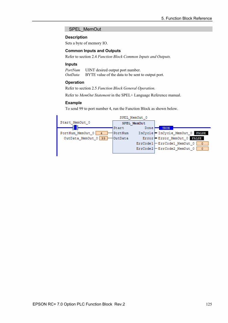
5. Function Block Reference
EPSON RC+ 7.0 Option PLC Function Block Rev.2 125
SPEL_MemOut Description Sets a byte of memory IO.
Common Inputs and Outputs Refer to section 2.4 Function Block Common Inputs and Outputs.
Inputs PortNum UINT desired output port number. OutData BYTE value of the data to be sent to output port.
Operation Refer to section 2.5 Function Block General Operation.
Refer to MemOut Statement in the SPEL+ Language Reference manual.
Example To send 99 to port number 4, run the Function Block as shown below.

5. Function Block Reference
126 EPSON RC+ 7.0 Option PLC Function Block Rev.2
SPEL_MemOutW Description Sets a word of memory IO.
Common Inputs and Outputs Refer to section 2.4 Function Block Common Inputs and Outputs.
Inputs PortNum UINT desired output port number. OutData WORD value of the data need to be sent to output port.
Operation Refer to section 2.5 Function Block General Operation.
Refer to MemOutW Statement in the SPEL+ Language Reference manual.
Example To send 99 to port number 15, run the Function Block as shown below.

5. Function Block Reference
EPSON RC+ 7.0 Option PLC Function Block Rev.2 127
SPEL_MemSw Description Reads a single bit of memory IO.
Common Inputs and Outputs Refer to section 2.4 Function Block Common Inputs and Outputs.
Inputs BitNum UINT desired memory bit number.
Operation Refer to section 2.5 Function Block General Operation.
Refer to MemSw Function in the SPEL+ Language Reference manual.
Example To read memory bit number 5, run the Function Block as shown below.

5. Function Block Reference
128 EPSON RC+ 7.0 Option PLC Function Block Rev.2
SPEL_MotorOff Description Turns robot motors off.
Common Inputs and Outputs Refer to section 2.4 Function Block Common Inputs and Outputs.
Operation Refer to section 2.5 Function Block General Operation.
Refer to Motor Statement in the SPEL+ Language Reference manual.
Example To turn off motors, run the Function Block as shown below.

5. Function Block Reference
EPSON RC+ 7.0 Option PLC Function Block Rev.2 129
SPEL_MotorOn Description Turns robot motors on.
Common Inputs and Outputs Refer to section 2.4 Function Block Common Inputs and Outputs.
Operation Refer to section 2.5 Function Block General Operation.
Refer to Motor Statement in the SPEL+ Language Reference manual.
Example To turn on motors, run the Function Block as shown below.

5. Function Block Reference
130 EPSON RC+ 7.0 Option PLC Function Block Rev.2
SPEL_Move Description Moves the arm from the current position to the specified position in a linear interpolation motion.
Common Inputs and Outputs Refer to section 2.4 Function Block Common Inputs and Outputs.
Inputs Point UINT desired point number. MaxTime DINT Function Block execution is timeout.
Operation Refer to section 2.5 Function Block General Operation.
Refer to Move Statement in the SPEL+ Language Reference manual.
Example To move the end effector to point P1, run the Function Block as shown below.

5. Function Block Reference
EPSON RC+ 7.0 Option PLC Function Block Rev.2 131
SPEL_NoFlip Description Sets the wrist orientation of the specified point to NOFLIP.
Common Inputs and Outputs Refer to section 2.4 Function Block Common Inputs and Outputs.
Inputs Point UINT desired point number.
Operation Refer to section 2.5 Function Block General Operation.
Refer to Wrist Statement in the SPEL+ Language Reference manual
Example To set point P2 orientation to NoFlip, run the Function Block as shown below.

5. Function Block Reference
132 EPSON RC+ 7.0 Option PLC Function Block Rev.2
SPEL_Off Description Turns an output bit off.
Common Inputs and Outputs Refer to section 2.4 Function Block Common Inputs and Outputs.
Inputs BitNum UINT desired output bit number.
Operation Refer to section 2.5 Function Block General Operation.
Refer to Off Statement in the SPEL+ Language Reference manual.
Example To turn off bit number 4, run the Function Block as shown below.

5. Function Block Reference
EPSON RC+ 7.0 Option PLC Function Block Rev.2 133
SPEL_On Description Turns an output bit on.
Common Inputs and Outputs Refer to section 2.4 Function Block Common Inputs and Outputs.
Inputs BitNum UINT desired output bit number.
Operation Refer to section 2.5 Function Block General Operation.
Refer to On Statement in the SPEL+ Language Reference manual.
Example To turn on bit number 4, run the Function Block as shown below.

5. Function Block Reference
134 EPSON RC+ 7.0 Option PLC Function Block Rev.2
SPEL_Out Description Sets an output byte to a given value.
Common Inputs and Outputs Refer to section 2.4 Function Block Common Inputs and Outputs.
Inputs PortNum UINT desired output port number. OutData BYTE desired output port value.
Operation Refer to section 2.5 Function Block General Operation.
Refer to Out Statement in the SPEL+ Language Reference manual.
Example To set port number 1 with value of 99, run the Function Block as shown below.

5. Function Block Reference
EPSON RC+ 7.0 Option PLC Function Block Rev.2 135
SPEL_OutW Description Sets an output word to a given value.
Common Inputs and Outputs Refer to section 2.4 Function Block Common Inputs and Outputs.
Inputs PortNum UINT desired output port number. OutData WORD desired output port value.
Operation Refer to section 2.5 Function Block General Operation.
Refer to OutWStatement in the SPEL+ Language Reference manual.
Example To set port number 0 with value of 99, run the Function Block as shown below.

5. Function Block Reference
136 EPSON RC+ 7.0 Option PLC Function Block Rev.2
SPEL_PowerHigh Description Sets the power level of robot to high.
Common Inputs and Outputs Refer to section 2.4 Function Block Common Inputs and Outputs.
Operation Refer to section 2.5 Function Block General Operation.
Refer to Power Statement in the SPEL+ Language Reference manual.
Example To set power high to the robot, run the Function Block as shown below.

5. Function Block Reference
EPSON RC+ 7.0 Option PLC Function Block Rev.2 137
SPEL_PowerLow Description Sets the power level of robot to low.
Common Inputs and Outputs Refer to section 2.4 Function Block Common Inputs and Outputs.
Operation Refer to section 2.5 Function Block General Operation.
Refer to Power Statement in the SPEL+ Language Reference manual.
Example To set power low to the robot, run the Function Block as shown below..

5. Function Block Reference
138 EPSON RC+ 7.0 Option PLC Function Block Rev.2
SPEL_ResetError Description Resets the robot controller error state. When an error has occurred while executing Function Block, you must execute SPEL_ResetError successfully before you execute another Function Block.
Note: If the controller has a system error, then it must be reset before SPEL_Init and other Function Blocks can execute successfully.
Common Inputs and Outputs Refer to section 2.4 Function Block Common Inputs and Outputs.
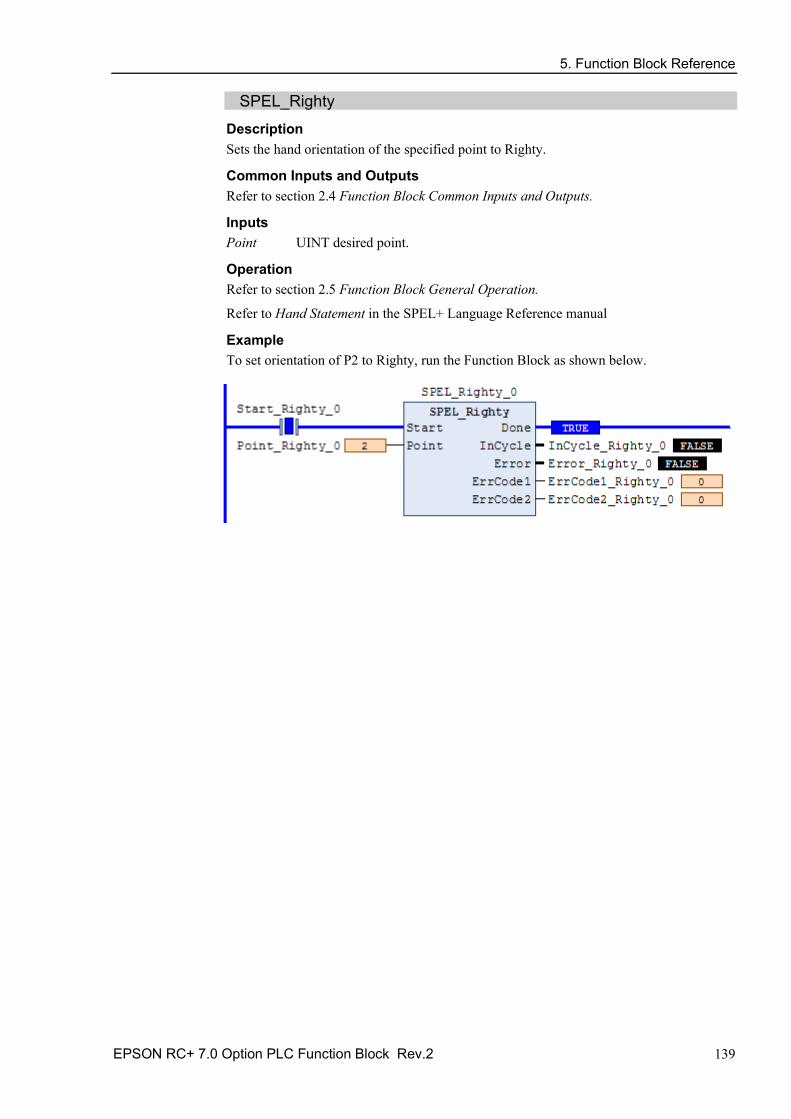
5. Function Block Reference
EPSON RC+ 7.0 Option PLC Function Block Rev.2 139
SPEL_Righty Description Sets the hand orientation of the specified point to Righty.
Common Inputs and Outputs Refer to section 2.4 Function Block Common Inputs and Outputs.
Inputs Point UINT desired point.
Operation Refer to section 2.5 Function Block General Operation.
Refer to Hand Statement in the SPEL+ Language Reference manual
Example To set orientation of P2 to Righty, run the Function Block as shown below.

5. Function Block Reference
140 EPSON RC+ 7.0 Option PLC Function Block Rev.2
SPEL_SavePoints Description Saves the current point data in robot controller memory to the default point file for robot 1 (robot1.pts) in the robot controller. To use this command, a valid RC+ project must exist in the controller. Typically, SavePoints is used to save points taught using the SPEL_Teach Function Block. When the controller starts up, it loads the project and the default point file, so the saved points are in memory.
Do not use a point file except for robot1.pts.
Common Inputs and Outputs Refer to section 2.4 Function Block Common Inputs and Outputs.
Operation Refer to section 2.5 Function Block General Operation.
Refer to SavePoints Statement in the SPEL+ Language Reference manual
Example To save all points in robot controller memory to the file robot1.pts in the robot controller, run the Function Block as shown below.

5. Function Block Reference
EPSON RC+ 7.0 Option PLC Function Block Rev.2 141
SPEL_Speed Description Sets the arm speed setting for PTP motion.
Common Inputs and Outputs Refer to section 2.4 Function Block Common Inputs and Outputs.
Inputs Speed UINT desired speed. ApproSpeed UINT desired approach speed, units are %. DepartSpeed UINT desired depart speed, units are %.
Operation Refer to section 2.5 Function Block General Operation.
Refer to Speed Statement in the SPEL+ Language Reference manual.
Example To set Speed to 100%, Approach, Depart Speed to 50%, run the Function Block as shown below.

5. Function Block Reference
142 EPSON RC+ 7.0 Option PLC Function Block Rev.2
SPEL_SpeedS Description Sets the arm speed setting of CP motion. This will set the depart, and approach speed as well.
Common Inputs and Outputs Refer to section 2.4 Function Block Common Inputs and Outputs.
Inputs Speed REAL desired speed. ApproSpeed REAL desired approach speed. DepartSpeed REAL desired depart speed.
Operation Refer to section 2.5 Function Block General Operation.
Refer to SpeedS Statement in the SPEL+ Language Reference manual.
Example To set Speed to 100, Approach, Depart Speed to 40, run the Function Block as shown below.

5. Function Block Reference
EPSON RC+ 7.0 Option PLC Function Block Rev.2 143
SPEL_Sw Description Reads the status of an input bit.
Common Inputs and Outputs Refer to section 2.4 Function Block Common Inputs and Outputs.
Inputs BitNum UINT desired input bit.
Outputs Status BOOL the value of the input bit.
Operation Refer to section 2.5 Function Block General Operation.
Refer to Sw Function in the SPEL+ Language Reference manual.
Example To read the value of input bit number 514, run the Function Block as shown below.

5. Function Block Reference
144 EPSON RC+ 7.0 Option PLC Function Block Rev.2
SPEL_Teach Description Teaches specified robot point in the robot controller to the current robot position.
Common Inputs and Outputs Refer to section 2.4 Function Block Common Inputs and Outputs.
Inputs Point UINT desired point.
Operation Refer to section 2.5 Function Block General Operation.
Refer to Here Statement in the SPEL+ Language Reference manual.
Example To teach current robot position for robot point P5, run the Function Block as shown below.

5. Function Block Reference
EPSON RC+ 7.0 Option PLC Function Block Rev.2 145
SPEL_ToolGet Description Gets the tool selection status.
Common Inputs and Outputs Refer to section 2.4 Function Block Common Inputs and Outputs.
Outputs ToolNum UINT the tool selected.
Operation Refer to section 2.5 Function Block General Operation.
Refer to Tool Function in the SPEL+ Language Reference manual.
Example To read the selected tool by the robot, run the Function Block as shown below.

5. Function Block Reference
146 EPSON RC+ 7.0 Option PLC Function Block Rev.2
SPEL_ToolSet Description Sets the tool.
Common Inputs and Outputs Refer to section 2.4 Function Block Common Inputs and Outputs.
Inputs ToolNum UINT the tool to be set.
Operation Refer to section 2.5 Function Block General Operation.
Refer to Tool Statement in the SPEL+ Language Reference manual.
Example To set current tool to 3, run the Function Block as shown below.

5. Function Block Reference
EPSON RC+ 7.0 Option PLC Function Block Rev.2 147
SPEL_WeightGet Description Gets the hand weight and arm length parameters.
Common Inputs and Outputs Refer to section 2.4 Function Block Common Inputs and Outputs.
Inputs HandWeight REAL weight of the hand. ArmLength REAL length of the arm.
Operation Refer to section 2.5 Function Block General Operation.
Refer to Weight Function in the SPEL+ Language Reference manual.
Example To get the current hand weight and arm length, run the Function Block as shown below.

5. Function Block Reference
148 EPSON RC+ 7.0 Option PLC Function Block Rev.2
SPEL_WeightSet Description Sets the weight parameter.
Common Inputs and Outputs Refer to section 2.4 Function Block Common Inputs and Outputs.
Inputs HandWeight REAL weight of the hand. ArmLength REAL length of the arm.
Operation Refer to section 2.5 Function Block General Operation.
Refer to Wait Statement in the SPEL+ Language Reference manual.
Example To set the hand weight and arm length, run the Function Block as shown below.
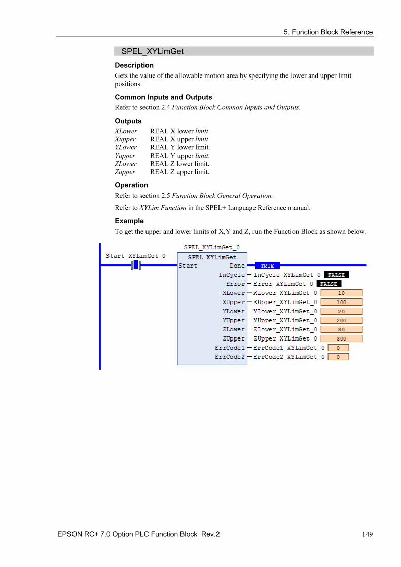
5. Function Block Reference
EPSON RC+ 7.0 Option PLC Function Block Rev.2 149
SPEL_XYLimGet Description Gets the value of the allowable motion area by specifying the lower and upper limit positions.
Common Inputs and Outputs Refer to section 2.4 Function Block Common Inputs and Outputs.
Outputs XLower REAL X lower limit. Xupper REAL X upper limit. YLower REAL Y lower limit. Yupper REAL Y upper limit. ZLower REAL Z lower limit. Zupper REAL Z upper limit.
Operation Refer to section 2.5 Function Block General Operation.
Refer to XYLim Function in the SPEL+ Language Reference manual.
Example To get the upper and lower limits of X,Y and Z, run the Function Block as shown below.

5. Function Block Reference
150 EPSON RC+ 7.0 Option PLC Function Block Rev.2
SPEL_XYLimSet Description Sets the allowable motion area by specifying the lower and upper limit positions.
Common Inputs and Outputs Refer to section 2.4 Function Block Common Inputs and Outputs.
Inputs XLower REAL X lower limit. Xupper REAL X upper limit. YLower REAL Y lower limit. Yupper REAL Y upper limit. ZLower REAL Z lower limit. Zupper REAL Z upper limit.
Operation Refer to section 2.5 Function Block General Operation.
Refer to XYLim Statement in the SPEL+ Language Reference manual.
Example To set the upper and lower limits of X,Y and Z, run the Function Block as shown below.

6. Error Codes
EPSON RC+ 7.0 Option PLC Function Block Rev.2 151
6. Error Codes Each Function Block has an Error output bit and two INT error codes: ErrCode1 and ErrCode2. The error output is set to high when an error has occurred, and ErrCode1, ErrCode2 indicate which error has occurred as described in the table below.
ErrCode1 ErrCode2 Description Cause/Remedy
0x200A (8202) 1 -9999 A robot controller error has occurred.
ErrCode2 is the robot controller error. See the Status Code / Error Code List.
0x200B (8203) 0
Command not accepted by the controller The controller is in a state where it cannot accept commands. Power cycle the controller.
0x3000 (12288)
0x280A (10250)
Function Block execution timeout Network communications was lost during command execution, or the command took too long to execute.
0x3000 (12288)
0x280B (10251)
Cannot execute instruction because of previous error or ExtReset input in the controller is low.
After any error has occurred, SPEL_ResetError must be executed.
0x3000 (12288)
0x280C (10252)
Cannot execute instruction because of invalid robot controller configuration.
Check that Remote I/O and PLC Vendor settings are correct in the robot controller.
0x3000 (12288) 1 -9999 A robot controller error has occurred.
ErrCode2 is the robot controller error. See the Status Code / Error Code List.

6. Error Codes
152 EPSON RC+ 7.0 Option PLC Function Block Rev.2