epson dfx-8500 service manual preface this manual describes functions, theory of electrical and...
TRANSCRIPT

EPSON
IMPACT SERIAL DOT MATRIX PRINTER
DFX-8500
SERVICE MANUAL
SEIKO EPSON CORPORATION
4009310

ii
NOTICE
��All rights reserved. Reproduction of any part of this manual in any form whatsoever
without SEIKO EPSON’s express written permission is forbidden.
��The contents of this manual are subjects to change without notice.
��All efforts have been made to ensure the accuracy of the contents of this manual.
However, should any errors be detected, SEIKO EPSON would greatly appreciate
being informed of them.
��The above notwithstanding SEIKO EPSON can assume no responsibility for any errors
in this manual or the consequences thereof.
EPSON is a registered trademark of SEIKO EPSON CORPORATION.
General Notice:
Other product names used herein are for identification purposes only and may be
trademarks or registered trademarks of their respective companies.
Copyright 1998 by SEIKO EPSON CORPORATION
Nagano, Japan

iii
PRECAUTIONS
Precautionary notations throughout the text are categorized relative to 1) personal injury and 2)
damage to equipment.
WARNING Signals a precaution which, if ignored, could result in serious or fatal personal injury.
Great caution should be exercised in performing procedures preceded by
WARNING Headings.
CAUTION Signals a precaution which, if ignored, could result in damage to equipment.
The precautionary measures itemized below should always be observed when performing
repair/maintenance procedures.
WARNING1. ALWAYS DISCONNECT THE PRODUCT FROM BOTH THE POWER SOURCE AND
PERIPHERAL DEVICES PERFORMING ANY MAINTENANCE OR REPAIR PROCEDURES.
2. NO WORK SHOULD BE PERFORMED ON THE UNIT BY PERSONS UNFAMILIAR WITH
BASIC SAFETY MEASURES AS DICTATED FOR ALL ELECTRONICS TECHNICIANS IN
THEIR LINE OF WORK.
3. WHEN PERFORMING TESTING AS DICTATED WITHIN THIS MANUAL. DO NOT
CONNECT THE UNIT TO A POWER SOURCE UNTIL INSTRUCTED TO DO SO. WHEN THE
POWER SUPPLY CABLE MUST BE CONNECTED, USE EXTREME CAUTION IN WORKING
ON POWER SUPPLY AND OTHER ELECTRONIC COMPONENTS.
CAUTION1. REPAIRS ON EPSON PRODUCT SHOULD BE PERFORMED ONLY BY EPSON CERTIFIED
REPAIR TECHNICIAN.
2. MAKE CERTAIN THAT THE SOURCE VOLTAGE IS THE SAME AS THE RATED VOLTAGE,
LISTED ON THE SERIAL NUMBER/RATING PLATE. IF THE EPSON PRODUCT HAS A
PRIMARY AC RATING DIFFERENT FROM AVAILABLE POWER SOURCE, DO NOT
CONNECT IT TO THE POWER SOURCE.
3. ALWAYS VERIFY THAT THE EPSON PRODUCT HAS BEEN DISCONNECTED FROM THE
POWER SOURCE BEFORE REMOVING OR REPLACING PRINTED CIRCUIT BOARDS
AND/OR INDIVIDUAL CHIPS.
4. IN ORDER TO PROTECT SENSITIVE MICROPROCESSORS AND CIRCUITRY, USE
STATIC DISCHARGE EQUIPMENT, SUCH AS ANTI-STATIC WRIST STRAPS, WHEN
ACCESSING INTERNAL COMPONENTS.
5. REPLACE MALFUNCTIONING COMPONENTS ONLY WITH THOSE COMPONENTS BY
THE MANUFACTURE; INTRODUCTION OF SECOND-SOURCE ICs OR OTHER
NONAPPROVED COMPONENTS MAY DAMAGE THE PRODUCT AND VOID ANY
APPLICABLE EPSON WARRANTY.

iv
PREFACE
This manual describes functions, theory of electrical and mechanical operations, maintenance, and
repair of DFX-8500.
The instructions and procedures included herein are intended for the experience repair technician,
and attention should be given to die precautions on the preceding page. The Chapters are
organized as follows:
CHAPTER 1. GENERAL DESCRIPTIONProvides a general product overview, lists specifications, and illustrates the main components of the
printer.
CHAPTER 2. OPERATING PRINCIPLESDescribes the theory of printer operation.
CHAPTER 3. DISASSEMBLY AND ASSEMBLYIncludes a step-by-step guide for product disassembly and assembly.
CHAPTER 4. ADJUSTMENTIncludes a step-by-step guide for adjustment.
CHAPTER 5. TROUBLESHOOTINGProvides EPSON-approved techniques for troubleshooting.
CHAPTER 6. MAINTENANCEDescribes preventive maintenance techniques and lists lubricants and adhesives required to
service the equipment.
APPENDIXDescribes connector pin assignments, circuit diagrams, circuit board component layout and
exploded diagram.
The contents of this manual are subject to change without notice.

v
REVISION SHEET
Revision Issued Data Contents
Rev. A May 18, 1998/ First issue
Rev. B June 25, 1998 Second issue due to minor correction on the
manual contents.
vi
TABLE OF CONTENTS
CHAPTER 1. GENERAL DESCRIPTIONCHAPTER 2. OPERATING PRINCIPLESCHAPTER 3. DISASSEMBLY AND ASSEMBLYCHAPTER 4. ADJUSTMENTCHAPTER 5. TROUBLESHOOTINGCHAPTER 6. MAINTENANCEAPPENDIX

CHAPTER 1 GENERAL DESCRIPTION
1.1 FEATURES.............................................................................................................1-1
1.2 SPECIFICATIONS..................................................................................................1-3 1.2.1 Printing Specification................................................................................................... .......... 1-3
1.2.2 Paper Feeding............................................................................................................ ............. 1-6
1.2.3 Electrical Specification ................................................................................................. ......... 1-6
1.2.4 Environmental Condition.................................................................................................. ..... 1-6
1.2.5 Reliability.............................................................................................................. ................... 1-6
1.2.6 Safety Approvals ......................................................................................................... ........... 1-7
1.2.7 CE Marking............................................................................................................... ............... 1-7
1.2.8 Acoustic Noise........................................................................................................... ............. 1-7
1.2.9 Ribbon Cartridge ......................................................................................................... ........... 1-7
1.2.10 Physical Specifications................................................................................................. ....... 1-7
1.2.11 Printable area .......................................................................................................... .............. 1-8
1.2.12 Paper and Media ......................................................................................................... ........ 1-12 1.2.12.1 Continuous paper (Single sheet and multi-part).................................................... 1-12 1.2.12.2 Labels .................................................................................................................... 1-14 1.2.12.3 Continuous Forms with Labels .............................................................................. 1-14 1.2.12.4 Overlapping Multi-part Form.................................................................................. 1-16 1.2.12.5 Perforation............................................................................................................. 1-16 1.2.12.6 Notes ..................................................................................................................... 1-16
1.3 INTERFACES.......................................................................................................1-19 1.3.1 Parallel Interface (Forward channel)................................................................................... 1- 19
1.3.2 Parallel Interface (Reverse channel)................................................................................... 1- 21
1.3.3 Serial Interface ......................................................................................................... ............. 1-22
1.3.4 Optional Interface ....................................................................................................... .......... 1-22
1.3.5 Interface Selection...................................................................................................... .......... 1-23
1.3.6 Prevention Hosts from Data Transfer Time-out................................................................. 1-23
1.4 OPERATING INSTRUCTIONS.............................................................................1-24 1.4.1 Control Panel ............................................................................................................ ............ 1-24
1.4.1.1 Switches .................................................................................................................. 1-25 1.4.1.2 Indicators................................................................................................................. 1-26
1.4.2 Errors and Buzzers....................................................................................................... ........ 1-27
1.4.3 DIP Switch Settings...................................................................................................... ........ 1-28
1.4.4 Functions ................................................................................................................ .............. 1-31 1.4.4.1 Usual operation ....................................................................................................... 1-31 1.4.4.2 Operation at Power On............................................................................................ 1-33 1.4.4.3 Built-in Detection ..................................................................................................... 1-34
1.4.5 Paper Memory Function.................................................................................................... ... 1-35
1.4.6 Initializations.......................................................................................................... ............... 1-36 1.4.6.1 Power-on Initialization ............................................................................................. 1-36 1.4.6.2 Software Initialization............................................................................................... 1-36 1.4.6.3 Panel Initialization.................................................................................................... 1-36
1.5 MAIN COMPONENT ...........................................................................................1-37 1.5.1 M-3I60 Printer Mechanism ................................................................................................. .. 1-38
1.5.2 Main Control Board (C204 MAIN Board)............................................................................. 1-39
1.5.3 C204 DRV Board ........................................................................................................... ........ 1-40

1.5.4 C204 DRV-B Board......................................................................................................... .......1-41
1.5.5 C204 SUB Board........................................................................................................... .........1-41
1.5.6 C204 PSB/PSE Board....................................................................................................... .....1-42
1.5.7 Control Panel............................................................................................................ .............1-43
1.5.8 Housing.................................................................................................................. ................1-43

GENERAL DESCRIPTION
Rev. B 1-1
1.1 FEATURESThe DFX-8500 is a 18-pin, serial, dot matrix printer with a maximum speed of 1120 characters per second(cps). It is designed for business use and provides high-speed, high-volume printing and continuous-sheethandling. The main features of the printer are:
�� Maximum printing speeds:�� 1120 cps (high-speed draft mode)�� 840 cps (draft mode)�� 210 cps (NLQ mode) at 10 cpi
�� Advanced paper handling:�� 10 inches per second (ips) paper feeding�� Paper jam detection�� Paper width detection�� Front and rear two-way push tractors�� Optional pull tractor�� Automatic paper back-out and loading from another paper path and paper park�� Automatic platen gap adjustment for paper thickness�� Automatic tear off�� Paper memory function�� Automatic paper path changing�� Auto cut mode enables the optional perforation cutter to cut the paper at the perforation.
�� Bi-directional parallel interface (IEEE-1284 nibble) and RS-232C serial interface standard�� EPSON ESC/P (upper compatible with DFX-8000) and IBM/LEXMARK 2381Plus emulation�� 35 character tables in the NLSP (National Language Support) version and 11 character tables in
the standard version�� 2 NLQ and 1 draft bit-map type faces and 8 barcode fonts are supported.�� Optional paper cutter and perforation cutter�� Upgraded data handling
�� 128 KB input buffer�� Automatic interface selection�� Type-B optional I/F cards
The figure below shows the DFX-8500.
Figure 1-1. DFX-8500 Exterior View

DFX-8500
Rev. B1-2
The following table shows options.
Table 1-1. OptionCode Name#8766 Ribbon cartridge#8767 Ribbon pack#8309 Pull tractor unitC81500X Paper cutterC81507X Perforation cutterC82305* Serial interface card (inch screw)C82306* Serial interface card (mm screw)C82307* 32-KB intelligent serial I/F card (inch screw)C82308* 32-KB intelligent serial I/F card (mm screw)C82310* 32-KB intelligent parallel I/F card (inch screw)C82311* 32-KB intelligent parallel I/F card (mm screw)C82312* Local Talk I/F cardC82313* 32KB IEEE-488 I/F cardC82314* Coax I/F cardC82315* Twinax I/F cardC82357* Ethernet I/F cardC82345* IEEE-1284 parallel I/F cardC82362 Ethernet I/F cardC82364 Ethernet I/F card

GENERAL DESCRIPTION
Rev. B 1-3
1.2 SPECIFICATIONSThis section describes the specifications for DFX-8500.
1.2.1 Printing Specification�� Print method : Impact dot matrix�� Number of pins : 18-pin (Refer to Figure 1-2.)�� Print pin arrangement : 9 x 2�� Print pin diameter : 0.0114 inches (0.29 mm)�� Color : Black�� Print direction : Bi-directional with logic seeking�� Print speed and printable columns: Refer to Table 1-2.
Table 1-2. Print Speed and Printable ColumnsPrint Mode Character Pitch Printable Columns Print Speed (cps)
Normal High DutyHigh speed draft 10 cpi 136 1120 1066Draft 10 cpi 136 840 800
12 cpi 163 1008 96015 cpi 204 630 630
Draft condensed 17 cpi 233 720 68520 cpi 272 840 800
Draft emphasized 10 cpi 136 420 400NLQ 10 cpi 136 210 200
12 cpi 163 252 24015 cpi 204 200 200
NLQ condensed 17 cpi 233 171 17120 cpi 272 200 200
Notes 1: The line including graphic B0h - FFh or download characters or bit image data will beprinted by “High duty" mode.
Notes 2: The line including special high duty download characters or bit image data will beprinted by one third speed of “High duty” mode.
Notes 3: When the print head temperature rises to the upper limit, the printer stops printing. Andwhen the print head temperature falls to the normal level, then the printer startsprinting again.
0.35 mm (1/72")
2.82 mm (8/72")
1.69 mm (1/15")
Figure 1-2. Printhead Pin Configuration

DFX-8500
Rev. B1-4
�� Resolution: Refer to Table 1-3.
Table 1-3. ResolutionPrint Mode Horizontal Density Vertical Density Adjacent Dot Print
High speed draft 90 dpi 72 dpi NoDraft 120 dpi 72 dpi NoDraft condensed 240 dpi 72 dpi NoDraft emphasized 120 dpi 72 dpi YesNLQ 240 dpi 144 dpi No
Bit image60, 72, 80, 90, 120 or 144
dpi72 dpi Yes
120 or 240 dpi 72 dpi No
�� Control code: ESC/P and IBM 2381 Plus emulation�� Character tables:
�� Standard version (11 character tables):Italic table PC437 (US, Standard Europe)PC850 (Multilingual) PC860 (Portuguese)PC861 (Icelandic) PC863 (Canadian-French)PC865 (Nordic) AbicompBRASCII Roman 8
� ISO Latin 1�� NLSP version (35 character tables):
Italic table PC437 (US, Standard Europe)PC850 (Multilingual) PC437 GreekPC852 (East Europe) PC853 (Turkish)PC855 (Cyrillic) PC857 (Turkish )PC866 (Russian) PC869 (Greek)MAZOIWA (Poland) Code MJK (CSFR)ISO 8859-7 (Latin / Greek) ISO Latin 1T (Turkish)Bulgaria (Bulgarian) Estonia (Estonia)PC 774 (LST 1283:1993) ISO 8859-2 (ISO Latin 2)PC 866 LAT. (Latvian) PC866 UKRPC 860 PC 861PC 865 PC APTECPC 708 PC 720PC AR864 PC 863(Canadian French) *Abicomp* BRASCII*Roman 8* ISO Latin 1*Hebrew 7* Hebrew 8*PC862*
Note: These tables can not be selected by DIP switch.
�� International character sets : 13 countriesUSA France GermanyU.K Denmark 1 Sweden
Italy Spain 1 Japan Norway Denmark 2 Spain 2
Latin AmericaNote : The international and legal characters are these 12 codes;
23h, 24h, 40h, 5Bh, 5Ch, 5Dh, 5Eh, 60h, 7Bh, 7Ch, 7Dh, 7Eh.
�� Typeface:�� Bit map font:
EPSON Draft 10 CPI, 12 CPI, 15 CPI EPSON Roman 10 CPI. 12 CPI, 15 CPI, Proportional EPSON Sans Serif 10 CPI, 12 CPI, 15 CPI, Proportional�� Bar code:
EAN-13 EAN-8 Interleaved 2 of 5 UPC-A UPC-E Code 39 Code 128 POSTNET

GENERAL DESCRIPTION
Rev. B 1-5
�� Character tables and type faces: Refer to Table 1-4.
Table 1-4. Character tables and type facesCharacter Table Bitmap Font
Standard version Italic Table EPSON DraftPC437 (US, Standard Europe) EPSON RomanPC850 (Multilingual) EPSON Sans SerifPC860 (Portuguese)PC861 (Icelandic)PC863 (Canadian French)PC865 (Nordic)AbicompBRASCIIRoman 8ISO Latin 1Italic table
NLSP version Italic Table EPSON DraftPC437 (US, Standard Europe) EPSON RomanPC850 (Multilingual) PC437 Greek EPSON Sans SerifPC852 (East Europe) PC853 (Turkish)PC855 (Cyrillic) PC857 (Turkish)PC866 (Russian) PC869 (Greek)MAZOWIA (Poland) Code MJK (CSFR)ISO 8859-7 (Latin / Greek) ISO Latin 1T (Turkish)Bulgaria (Bulgarian) Estonia (Estonia)PC 774(LST 1283:1993) ISO 8859-2 (ISO Latin 2)PC 866 LAT.( Latvian) PC 866 UKRPC 860 PC 861PC 865 PC APTECPC 708 PC 720PC AR864 PC 863*1
Abicomp*1 BRASCII*1
Roman 8*1 ISO Latin 1Hebrew 7*1 Hebrew 8*1
PC 862*1
*1) These tables can not be selected by DIP switches.Note : ESC R command is effective on all the character tables.
��Input data buffer: 0K byte or 128 K bytes (depend on DIP switch settings)

DFX-8500
Rev. B1-6
1.2.2 Paper Feeding�� Feeding method: Push tractor feed (front / rear)
Push and pull tractor feed (front / rear)�� Feeder: Front push tractor, rear push tractor, pull tractor (option)�� Paper insertion side alignment :� Left�� Paper path: Tractor (front in, rear in, top out)�� Line spacing: 1 / 6 inches or programmable in increments of 1 / 216 inches.�� Feed speed:
�� 1/ 6-inch feed: 26.5 ms�� Continuous feed: 0.251 mps (m/s).
9.9 ips (inch/sec)Note : The feeding speed will be reduced to 0.152 mps (6.0 ips) when the pull tractor is mounted.
1.2.3 Electrical Specification�� 120 V version:
�� Rated voltage : 120 V AC�� Input voltage range : 99 to 132 V AC�� Rated frequency range : 50 to 60 Hz�� Input frequency range : 49.5 to 60.5 Hz�� Rated current : 3.5 A (max.7.5 A)�� Power consumption : Approx.160 W (ISO/IEC10561 Letter pattern)
Energy Star compliant�� Insulation resistance : 10 M ohms min. (between AC line and chassis, 500 V DC)�� Dielectric strength : 1000 AC Vrms. 1 min. or
1200 AC Vrms. 1 sec. (between AC line and chassis)�� 220 - 240 V version:
�� Rated voltage : 220 to 240 V AC�� Input voltage range : 198 to 264 V AC�� Rated frequency range : 50 to 60 Hz�� Input frequency range : 49.5 to 60.5 Hz�� Rated current : 1.4 A (max.3.5 A)�� Power consumption : Approx.160 W (ISO/IEC10561 Letter pattern)
Energy Star compliant�� Insulation resistance : 10 M ohms min. (between AC line and chassis, 500 V DC)�� Dielectric strength : 1500 AC Vrms. 1 min. (between AC line and chassis)
1.2.4 Environmental Condition�� Temperature : 5 to 35 oC (operating)
-30 to 60 oC (non-operating)
�� Humidity : 10 to 80 % RH (operating) *1)5 to 85 % RH (non-operating) *1)
�� Resistance to shock : 1 G, within 1 ms (operating)2 G, within 2 ms (non-operating) *2)
�� Resistance to vibration : 0.25 G, 10 to 55 Hz (operating)0.50 G, 10 to 55 Hz (non-operating) *2)
*1: Without condensation*2: With shipment container
1.2.5 Reliability�� Total print volume : 26 million lines (except print head)�� MTBF : 10,000 POH (25 % duty)�� Print head life : 400 million characters at 14 dots/character�� Ribbon life : 15 characters at 14 dots /character

GENERAL DESCRIPTION
Rev. B 1-7
1.2.6 Safety Approvals�� 120 V version:
�� Safety standards : UL1950 with D3CSA C22.2 No.950 with D3
�� EMI : FCC part 15 subpart B class BCSA C108.8 class B
�� 230 V version:�� Safety standards : EN60950 (VDE, NEMKO)�� EMI : EN55022 (CISPR pub.22) class B
AS / NZS 3548 class B
1.2.7 CE Marking�� 230 V version:
�� Low Voltage Directive 73/23/EEC : EN60950�� EMC Directive 89/336/EEC : EN55022 class B� EN61000-3-2� EN61000-3-3� EN50082-1� IEC801-2� IEC801-3� IEC801-4
1.2.8 Acoustic Noise�� Level: 58 dB(A) (ISO 7779 pattern)
1.2.9 Ribbon Cartridge�� Type : Fabric�� Color : Black�� Ribbon life : 15 million characters (draft 10 cpi, 14 dots / character)�� Dimensions : 506.0 mm (W) x 123.5 mm (D) x 23.0 mm (H)
1.2.10 Physical Specifications�� Dimensions : 700 mm (W) x 382 mm (D) x 369 mm (H)�� Weight : APPROX. 29 Kg
DFX-8500
Rev. B1-8
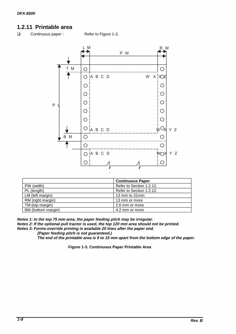
1.2.11 Printable area�� Continuous paper : Refer to Figure 1-3.
W X Y ZA B C D
A B C D W X Y Z
A B C D W X Y Z
L M R M
B M
T M
P L
P W
.
Continuous PaperPW (width) Refer to Section 1.2.12.PL (length) Refer to Section 1.2.12.LM (left margin) 13 mm to 31mmRM (right margin) 13 mm or moreTM (top margin) 2.6 mm or moreBM (bottom margin) 4.2 mm or more
Notes 1: In the top 75 mm area, the paper feeding pitch may be irregular.Notes 2: If the optional pull tractor is used, the top 120 mm area should not be printed.Notes 3: Forms-override printing is available 20 lines after the paper end.
(Paper feeding pitch is not guaranteed.) The end of the printable area is 9 to 15 mm apart from the bottom edge of the paper.
Figure 1-3. Continuous Paper Printable Area

GENERAL DESCRIPTION
Rev. B 1-9
�� Labels : Refer to Figure 1-4.
L M R M
B M
T M
P L
P W
L a b e l L a b e l
L a b e l L a b e l
.
Continuous PaperPW (width) Refer to Section 1.2.12.PL (length) Refer to Section 1.2.12.LM (left margin) 13 mm to 31mmRM (right margin) 13 mm or moreTM (top margin) 2.6 mm or moreBM (bottom margin) 4.2 mm or more
Notes 1: Feeding backward or paper (PATH) selection are prohibited.Notes 2: If In the top 75 mm area, the paper feeding pitch may be irregular.Notes 3: If the optional pull tractor is used, the top 120 mm area should not be printed..Notes 4: Forms-override printing is available 20 lines after the paper end.
(Paper feeding pitch is not guaranteed.) The end of the printable area is 9 to 15 mm apart from the bottom edge of the paper.
Figure 1-4. Label Printable Area

DFX-8500
Rev. B1-10
�� Continuous forms with labels : Refer to Figure 1-5.
A B C D W X Y Z
L M R M
B M
T M
P L
P W
P r i n t a b l e A r e a
L O L R O LL a b e l
B O L
T O L
L F L R F L
L a b e l
B F L
T F L
L a b e l
N o n P r i n t a b l e A r e a
Continuous PaperPW (width) Refer to Section 1.2.12.PL (length) Refer to Section 1.2.12.LM (left margin) 13 mm to 31mmRM (right margin) 13 mm or moreTM (top margin) 2.6 mm or moreBM (bottom margin) 4.2 mm or moreLFL (left margin from label) 65 mm or moreRFL (right margin from label) 65 mm or moreTFL (top margin from label) 12.5 mm or moreBFL (bottom margin from label) 12.5 mm or moreLOL (left margin on label) 5 mm or moreROL (right margin on label) 5 mm or moreTOL (top margin on label) 2 mm or moreBOL (bottom margin on label) 2 mm or more
Notes 1: Feeding backward or paper (PATH) selection are prohibited.Notes 2: If In the top 75 mm area, the paper feeding pitch may be irregular.Notes 3: If the optional pull tractor is used, the top 120 mm area should not be printed..Notes 4: Forms-override printing is available 20 lines after the paper end.
(Paper feeding pitch is not guaranteed.) The end of the printable area is 9 to 15 mm apart from the bottom edge of the paper.
Figure 1-5. Continuous Forms with Labels Printable Area

GENERAL DESCRIPTION
Rev. B 1-11
�� Overlapping multi-part forms : Refer to Figure 1-6.
L M
P e r f o r a t i o n s
C a r r i e r
P W
P L
N A
O L
B M
T M
R M
Continuous PaperPW (width) Refer to Section 1.2.12.PL (length) Refer to Section 1.2.12.LM (left margin) 19 mm to 31mmRM (right margin) 19 mm or moreTM (top margin) 21.2 mm or moreBM (bottom margin) 4.2 mm or moreOL (overlapping length) Less than 13.3 mmNA (non printable area) 25.4 mm or more
Notes 1: Feeding backward or paper (PATH) selection are prohibited.Notes 2: If In the top 75 mm area, the paper feeding pitch may be irregular.Notes 3: If the optional pull tractor is used, the top 120 mm area should not be printed..Notes 4: Forms-override printing is available 20 lines after the paper end.
(Paper feeding pitch is not guaranteed.) The end of the printable area is 9 to 15 mm apart from the bottom edge of the paper.
Figure 1-6. Overlapping Multi-part Form Printable Area

DFX-8500
Rev. B1-12
1.2.12 Paper and Media
1.2.12.1 Continuous paper (Single sheet and multi-part)
Table 1-5. Continuous PaperFront Entry Rear Entry
Minimum Maximum Minimum MaximumWidth (inch)
(mm)4.0101
16.0406
4.0101
16.0406
Length (inch)(mm)
4.0101
17.0431
4.0101
17.0431
Copies 1 original + 6 copies 1 original + 5 copiesTotal Thickness (inch)
(mm)0.00250.065
0.0210.53
0.00250.065
0.0180.46
Weight(not multi-part)
(g/m2)(lb)
52.614
82.722
52.614
82.722
Weight(one sheet of multi-part)
(g/m2)(lb)
41.411
56.415
41.411
56.415
Quality Plain paper, Reclaimed paper, Carbonless multi-part formsMulti-part binding • Rough bindings of multi-part paper cause paper jam.
• The each sheet of multi-part paper should normally be put together byspot-gluing, paper-stapling, tape stitching. Spot-gluing is recommendedfor the better printing quality.
• Spot-gluing must be applied on both sides of paper (Refer to Figure 1-7.).
• The spot-glued parts must be pressed flat. There must be no creases inthe paper.
• The paper-stapling must be applied from the front of paper and thepaper must be flat (Refer to Figure 1-8.).
• Paper-stapling must be applied for both feeding directions (Refer toFigure 1-9.).
• The paper-stapling should be flat (Refer to Figure 1-10.).• Never use metal staples.• The position of binding must be outside of printable area.• Multi-part paper should be bound firmly to each other and the binding
must not be too large.
Perforation Refer to Section 1.2.12.5.Notes Refer to Section 1.2.12.6.
Figure 1-7. Dotted Paste Positions

GENERAL DESCRIPTION
Rev. B 1-13
Figure 1-8. Paper-stapling Height
Figure 1-9. Paper-sta plin g Method 1
Figure 1-10. Paper -stapling Method 2

DFX-8500
Rev. B1-14
1.2.12.2 Labels
Table 1-6. LabelsFront Entry Rear Entry
Minimum Maximum Minimum MaximumLabel Size Refer to Figure 1-11. -Backing Sheet Width (inch)
(mm)4.0101
16.0406
- -
Backing Sheet Length (inch)(mm)
3.589
17.0431
- -
Label Thickness (inch)(mm)
0.00.0
0.00470.12
- -
Total Thickness (inch)(mm)
0.00250.065
0.00750.19
- -
Quality AVERY CONTINUOUS FORM LABELS,AVERY MINI-LINE LABELS, or thesame quality labels
-
Perforation Refer to section 1.2.12.5.Notes • The easy-cone-off label should not be used.
• Every label must be put on the carrier.• Each comer of those labels must be rounded.• Each label and backing sheet should not have any folds or creases.• Between each label, there should be the same sheet as those labels.• The backing sheet must be continuous paper.• Labels should be inserted from front entrance.
Refer to Section 1.2.12.6.
W
H
Width HeightInch mm Inch mm2.5 63.5 15/16 23.84.0 101 15/16 23.84.0 101 17/16 27.0
Figure 1-11. Label Size

GENERAL DESCRIPTION
Rev. B 1-15
1.2.12.3 Continuous Forms with Labels
Table 1-7. Continuous Forms with LabelsFront Entry Rear Entry
Minimum Maximum Minimum MaximumLabel Size Refer to Section 1.2.12.2. -Width (inch)
(mm)4.0101
16.0406
- -
Length (inch)(mm)
4.0101
17.0431
- -
Weight(not multi-part)
(g/m2)(lb)
52.614
82.722
- -
Weight(one sheet of multi-part)
(g/m2)(lb)
41.411
56.415
Label Thickness (inch)(mm)
0.00.0
0.00470.12
Total Thickness (inch)(mm)
0.00250.065
0.0210.53
- -
Quality (Multi-part forms) Plain paper, reclaimed paper, carbonlessmulti-part forms
Quality (Label) AVERY CONTINUOUS FORM LABELS,AVERY MNI-LINE LABELS, or the samequality labels
Multi-part binding • Rough bindings of multi-part paper cause paper jam.• The each sheet of multi-part paper should normally be put
together by spot-gluing, paper-stapling, tape stitching. Spot-gluingis recommended for the better printing quality.
• Spot-gluing must be applied on both sides of paper (Refer toFigure 1-7.).
• The spot-glued parts must be pressed flat. There must be nocreases in the paper.
• The paper-stapling must be applied from the front of paper and thepaper must be flat (Refer to Figure 1-8.).
• Paper-stapling must be applied for both feeding directions (Referto Figure 1-9.).
• The paper-stapling should be flat (Refer to Figure 1-10.).• Never use metal staples.• The position of binding must be outside of printable area.• Multi-part paper should be bound firmly to each other and the
binding must not be too large.Perforation Refer to Section 1.2.12.5.Notes • The easy-cone-off label should not be used.
• Every label must be put on the carrier.• Each comer of those labels must be rounded.• Each label and backing sheet should not have any folds or
creases.• Between each label, there should be the same sheet as those
labels.• The backing sheet must be continuous paper.• Continuous forms with labels should be inserted from front
entrance.
Refer to Section 1.2.12.6.

DFX-8500
Rev. B1-16
1.2.12.4 Overlapping Multi-part Form
Table 1-8. Overlapping Multi-part FormFront Entry Rear Entry
Minimum Maximum Minimum MaximumWidth (inch)
(mm)4.0101
16.0406
- -
Length (inch)(mm)
4.0101
17.0431
- -
Weight(not multi-part)
(g/m2)(lb)
52.614
82.722
- -
Weight(one sheet of multi-part)
(g/m2)(lb)
41.411
56.415
- -
Copies 1 original + 5 copies + 1 backingsheet
-
Total Thickness(print area)
(inch)(mm)
0.00250.065
0.0210.53
- -
Total Thickness(overlap area)
(inch)(mm)
0.0050.13
0.0280.70
- -
Overlapping Length (inch)(mm)
more than 0more than 0
0.3910
- -
Quality (multi-part forms) Plain paper, reclaimed paper,carbonless multi-part forms
-
Multi-part binding • Multi-part paper must be bound at the top side by spot-gluing (Figure 1-12.).
• The bindings must not be too hard. And there should not be any spiltglue.
• The position of binding must be outside of printable area.• Multi-part paper should be bound firmly to each other and the binding
must not be too large.Perforation Refer to Section 1.2.12.5.Notes • Overlapping multi-part form should be inserted from front entrance.
Refer to Section 1.2.12.6.
1.2.12.5 Perforation• Weak horizontal and vertical perforations cause paper jams.D• The length ratio of the cut part and uncut part of perforations must be more than 3 to 1 and less than 5
to 1 (Refer to Figure 1-13.).• Horizontal perforations must have an uncut part in each end of the paper (Refer to Figure 1-14.).• At the intersection of horizontal and vertical perforations, the cut part of the perforations must not cross
each other (Refer to Figure 1-15.).• The raised part at the perforation must be less than 1 mm when the bottom layer kept by force (Refer
to Figure 1-16.).
1.2.12.6 Notes• Clean paper (with no folds, creases, tears) should be used (Refer to Figure 1-17.).• The sprocket hole must be circular. The hole may have teeth (Refer to Figure 1-18.).• The sprocket hole of each layer must not be shifted (Refer to Figure 1-19.).• The litter of sprocket holes must be removed from the paper.• Paper should be fan-folded at horizontal perforations. Never use one that is not fan-folded property
(Refer to Figure 1-20.).• No hole is acceptable in the printable area.• Paper must be torn off accurately along perforations.

GENERAL DESCRIPTION
Rev. B 1-17
1 9 - 3 1
1 3 + 3Page Length
P a g e W i d t h S p o t - g l u e d p a r t
L o w e r e d g eS p o t - g l u e d p s r t
P e r f o r a t i o n o f b a s e s h e e t
4.2 or more
21.2 or more
S p o t - g l u e d p a r t
B a s e s h e e t
M u l t i - p a r t c u t s h e e t
21.2 or more
1 3 + 3
1 9 o r m o r e
U n i t : m m
Figure 1-12. Paper Width Overlapping Area
Figure 1-13. Perforations 1 Figure 1-14. Perforations 2

DFX-8500
Rev. B1-18
Figure 1-17. Unsuitable Paper
a) b) c)
Figure 1-15. Perforations 3
Figure 1-18. Sprocket Hole 1
Figure 1-19. Sprocket Hole 2
Figure 1-16. Raised Portion at a Perforation
Figure 1-20. Bad Folded Paper

GENERAL DESCRIPTION
Rev. B 1-19
1.3 INTERFACES The DFX-8500 is equipped with parallel interface, serial interface, and optional Type-B interface card.
This section presents the specifications for each interface type.
1.3.1 Parallel Interface (Forward channel)�� Data transmission mode: 8-bit parallel, IEEE-1284 compatibility mode�� Synchronization: /STROBE pulse�� Connector type: 57-30360 (AMPHENOL) 36-pin plug or equivalent�� Handshaking: BUSY and /ACK handshakingNotes 1: BUSY signal is set high before setting either /ERROR low or PE high and held high until
all these signals return to their inactive state. BUSY signal is at a high level in the followingcases.
��During data entry (see data transmission timing)��When input data buffer is full.��During /INIT signal is at a low level or during hardware initialization��During printer error (see /ERROR signal)��During test printing or during setting printing��During SelecType��When the parallel interface is not selected.
Notes 2: /ERROR signal is at a low level when the printer is in one of the following states.��Printer hardware error (fatal error)��Paper out error��Paper jam error��Cover open status��Incomplete paper change��Paper size error��Ribbon jam error
Notes 3: PE signal is at a high level during paper out error.
�� Data transmission timing: Refer to Figure 1-21.
Parameter Minimum Maximum Parameter Minimum Maximumt setup 500 ns --- t ack 500 ns 10 ust hold 500 ns --- t nbusy 0 ---t stb 500 ns --- t next 0 ---
t ready 0 --- tt-out* --- 120 nst busy --- 500 ns tt-in** --- 200 nst reply --- ---
Note: * Rise and fall time of output signals ** Rise and fall time of input signals.
Figure 1-21. Data Transmission Timing
D A T A
S T R O B E
B U S Y
A C K N L G
t s e t u p
t r e a d y
t b u s y
t s t b
t r e p l y t a c k t n b u s y
t n e x t
t h o l d
D A T A ( n ) D A T A ( n + 1 )

DFX-8500
Rev. B1-20
�� Signal Level: TTL-level compatible, IEEE-1284 level 1 deviceRefer to Table 1-9.
Table 1-9. Signal LevelParameter Minimum Maximum ConditionVOH* - 5.5 VVOL* -0.5 V -IOH* - 0.32 mA VOH = 2.4 VIOL* - 12 mA VOL = 0.4 VCO - 50 pFVIH - 2.0 VVIL 0.8 V -IIH - 0.32 mA VIH = 2.4 VIIL - 12 mA VIL = 0.8 VCI - 50 pF
Note: * A low logic level on the logical high signal is 2.0 V or less when the printer is powered off.And this signal is equal or exceeding 3. 0 V when the printer is powered on. The receivershall provide an impedance equivalent to 7.5 K ohms to ground.
��Connector pin assignments and signals: Refer to Table 1-10.
Table 1-10. Signal and Connector Pin Assignment (Forward channel)
Pin No. Signal Name Return GND pin In/Out* Functional Description1 /STROBE 19 In The strobe pulse. Read-in of data is performed
at the falling edge of this pulse.2-9 DATA 0-7 20-27 In The DATA0 through DATA7 signals represent
data bits 0 to 7, respectively. Each signal is athigh level when data is logical 1 and low levelwhen data is logical 0.
10 /ACKNLG 28 Out This signal is a negative pulse indicating thatthe printer can again accept data.
11 BUSY 29 Out A high signal indicates that the printer cannotreceive data.
12 PE 28 Out A high signal indicates paper-out error.13 SLCT 28 Out Always at high level when the printer is
powered on.14 /AFXT 30 In Not used.31 /INIT 30 In The falling edge of a negative pulse or a low
signal on this line causes the printer to initialize.Minimum 50 us pulse is necessary.
32 /ERROR 29 Out A low signal indicates printer error condition.36 /SLIN 30 In Not used.18 Logic H - Out Pulled up to +5V via 3.9K ohm resistor.35 +5V - Out Pulled up to +5V via 3.3K ohm resistor.17 Chassis GND - - Chassis GND.
16,33,19,30 GND - - Signal GND.15,34 NC - - Not connected.
Note: * In/Out refers to the direction of signal flow from the printer’s point of view.

GENERAL DESCRIPTION
Rev. B 1-21
1.3.2 Parallel Interface (Reverse channel)�� Data transmission mode: IEEE-1284 nibble mode�� Connector type: 57-30360 (AMPHENOL) 36-pin plug or equivalent�� Synchronization: No Info.�� Handshaking: No info.�� Data transmission timing: No info.�� Signal Level: TTL-level compatible, IEEE-1284 level 1 device�� Extensibility request : The printer responds to the extensibility request in the affirmative,
when the request is 00h or 04h, which mean:00h : Request nibble mode of reverse channel transfer04h : Request device ID in nibble mode of reverse channel transfer
�� Device ID :[00h][3Ah]MPG:EPSON;CMD:ESCP9,PRPII9,BDC;MDL:DFX-8500;CLS:PRINTER;
��Connector pin assignments: Refer to Table 1-11.
Table 1-11. Signal and Connector Pin Assignment (Reverse channel)
Pin No. Signal Name I/O* Description1 /STROBE IN HostCIk: This signal is a strobe pulse used to read extension
request values from the host computer during negotiation.2-9 DATA 1-8 IN The signals are data bits of extension request Values during
negotiation. This printer supports following values: 0000 0100: Request Device ID (by nibble mode sending) 0000 0000: Request nibble mode
10 /ACKNLG OUT PtrCIk: Printer data sending clock.11 BUSY OUT PtrBusy: Printer sending data bits 3 and 7 during data transfer to
the host computer12 PE OUT AckDataReq: Printer sending data bits 2 and 6 during data transfer
to the host computer13 SLCT OUT Xflag: Printer sending data bits 2 and 6 during data transfer to the
host computer.14 /AUTO-FEED IN HostBusy: This signal informs the printer of the host computer
state. When the signal is HIGH, the host computer cannot acceptdata.
15 NC - Not used.16 GND - Logic ground level17 CHASSISGND - Connected to the printer chassis. The printer chassis GND and the
signal GND are connected to each other.18 NC - Not connected.19-30 GND - Ground level for the twisted pair return signal.31 /INIT IN nlnit: High level fixed32 /ERROR OUT nDataAvaiI: Printer sending data bits 0 and 4 during data transfer to
the host computer.33 GND - Same as for ins19to30.34 NC - Not used.35 +5 - Pulled up to +5V through 1.0K ohm resistor.36 /SLCT IN IN 1284Active: If this signal is set to HIGH, this printer active
P1284(reverse mode).Note: * In/Out refers to the direction of signal flow from the printer’s point of view.

DFX-8500
Rev. B1-22
1.3.3 Serial Interface�� Synchronization : Asynchronous�� Signal level (ELA-232D) :
�� MARK (logical 1) : -3Vto-25V�� SPACE (logical 0) : +3Vto+25V
�� Word length :�� Start bit : 1 bit�� Data bit : 8 bit�� Parity bit : Odd, Even, Non, of Ignore�� Stop bit : 1 bit or more
�� Baud rate : 2400, 4800, 9600 or 19200 bps�� Handshaking : DTR signal or X-ON / X-OFF
�� DTR=MARK, X-OFF : Indicates that the printer cannot receive data.�� DTR=SPACE, X-ON : Indicates that the printer is ready to receive data.
Note: The DTR signal is MARK and X-OFF code (DC3, 13h) is transmitted when the rest of the input buffer becomes 256-byte. The DTR signal is SPACE and X-ON code (DC1, 11h) is transmitted when the rest of the input buffer is regained 256-byte.
�� Error handling : When parity error is detected, the received byte is changed to the� "*" character code. Overrun error and framing error are ignored.�� Connector : 25 pin sub-miniature D-shell connector (female)�� Connector pin assignment and signals : Refer to Table 1-12.
Table 1-12. Signal and Connector Pin Assignment (EIA-232D)
Pin No. Signal Name In / Out* Functional Description2 TXD Out Transmit data.20 DTR Out Indicates that the printer is ready to receive data or not.11 REV Out Connected directly to the DTR signal.4 RTS Out Request to send. always SPACE level when the printer is
powered on. Pulled up to +12 V via 4.7K-ohm resistor.3 RXD In Receive data7 Signal GND - Signal GND1 Chassis
GND- Chassis GND
Other NC - Not used. Not connected.Note: * In/Out refers to the direction of signal flow from the printer’s point of view.
1.3.4 Optional InterfaceType-B and Type-B level 2 optional interfaces are available (Refer to Table 1-1.).

GENERAL DESCRIPTION
Rev. B 1-23
1.3.5 Interface SelectionThe printer has three interfaces; the parallel interface, serial interface, and optional Type-B interface.These interfaces are selected manually by DIP SW or selected automatically.
�� Manual selection:� One of three interfaces can be selected by DIP SW setting.�
�� Automatic selection:The automatic interface selection is enabled by DIP SW setting. In this automatic interfaceselection mode, the printer is initialized to the idle state scanning which interface receives datawhen it is powered on. Then the interface that receives data first is selected. When the host stopsdata transfer and the printer is in stand-by state for the seconds specified by DIP SW setting, theprinter is returned to the idle state. As long as the host sends data or the printer interface is busystate, the selected interface is let as it is.
�� Interface state and interface selection:When the parallel interface is not selected, the interface got into a busy state. When the serialinterface is not selected, the interface sends X-OFF and sets the DTR signal MARK. When theoptional interface is not selected, the printer sends disable commands to the optional interface.When the printer is initialized or returned to the idle state, the parallel interface got into a readystate, the serial interface sends X-ON and sets the DTR SPACE and the printer sends enablecommands to the optional interface.Caution that the interrupt signal such as a /INIT signal on the parallel interface is not effectivewhile that interface is not selected.
1.3.6 Prevention Hosts from Data Transfer Time-outGenerally, hosts abandons data transfer to peripherals when a peripheral is in busy state for dozens ofseconds continuously. To prevent hosts from this kind of time-out, the printer receives data very slowly,several bytes per minute, even if the printer is in busy state. This slowdown is started when the rest of theinput buffer becomes several hundreds of bytes. At last, when the input buffer is full, the printer is in busystate continuously.

DFX-8500
Rev. B1-24
1.4 OPERATING INSTRUCTIONSThis section describes the functions performed through the control panel, such as test print, hexadecimaldump, and paper memory function.
1.4.1 Control PanelThe printer control panel gives you easy control over most common printer operations. The panel consistsof indicator lights and buttons.
P a p e r S e l e c t
P o w e rP a p e rO u t
R i b b o n
F o n t P i t c h C o p yT o p o fF o r m
T e a r O f f
L F / F FL o a d
P a u s e
R e s e t
3 s e c
T r a c t o r S e l e c t
P A P E R S E L E C T
F r o n t / R e a r
S p e r D r a f tD f a f tR o m a nS a n s s e r i f
1 0 c p i1 2 c p i1 5 c p i1 7 c p i2 0 c p iP S
M i c r oF e e d
L E D O f f L E D O n
Figure 1-22. Control Panel

GENERAL DESCRIPTION
Rev. B 1-25
1.4.1.1 SwitchesThe control panel contains eleven switches.
��Operation in normal mode:In normal mode, pressing panel switches executes following function. Refer to Table 1-13.
Table 1-13. Switch Function in Normal Mode
Switch FunctionFront / Rear Change the front and rear paper path alternately.Pause ��Alternates printing and no-printing status.
��Enables reset function, holding it down for three seconds.Micro Feed ↑ Executes micro feed forward.Micro Feed ↓ Executes micro feed backward.LF / FF Load ��Loads the paper when the paper is empty.
��Executes line feed, pressing it shortly.��Executes form feed, holding it down for a few seconds.
TOF (top of form) ��Set current point to top of form when the cover opens.��Enables loading position adjustment and tear off position adjustment
when the cover opens.Tear Off Advances continuous paper to the Tear off position adjustment.Copy Alternates copy mode or not.Pitch Selects pitch.Font Selects font.Paper Select Selects paper No.
��Operation at power on:Tuning the printer on while pressing panel switches executes the function shown in Table 1-14.
Table 1-14. Switch Function at Power On
Switch FunctionLF / FF Load Draft self testTear off NLQ self testTear off and LF / FF Data dumpPause DIP SW setting printLF / FF Load and Micro Feed ↓ and Pause*1) Clear EEPROM at area 2Pause and Front / Rear*2) Clear EEPROM at area 1Copy Clear driving line count for ribbon change timingPaper Select Paper memoryTear Off, Micro Feed ↑, and Front/Rear Mechanism adjustment (Refer to Chapter 4.)Tear Off, Micro Feed ↓, and Front/Rear Platen gap adjustment (Refer to Chapter 4.)Micro Feed ↑ and Micro Feed ↓ Measurement seeking (Refer to Chapter 4.)Notes1: All of mechanism adjustment values are cleared. Then it requires the printer mechanism
adjustment.Notes2: All of user setting value is replaced with the factory setting value.

DFX-8500
Rev. B1-26
1.4.1.2 IndicatorsThe control panel contains fifteen LEDs.
��Rear (2) (Green / Red) :��Green LED on when the rear paper path is selected with paper.��Red LED on when the rear paper path is selected without paper.��Off when the front paper path is selected.
��Front (2) (Green / Red) :��Green LED on when the front paper path is selected with paper.��Red LED on when the front paper path is selected without paper.��Off when the rear paper path is selected.
��Pause (Orange) :��The LED on when the printer is paused, and it is off when the printer is not paused.��The LED blinks when the printer is in the print head hot status.
��Top of Form (Green) :��The LED on when the top of form position is adjustable and tear off position is adjustable.
��Tear Off (Green) :��The LED on when the paper is in Tear off position and it is off when the paper is out of the Tear-off
position.��Copy (Green) :
��The LED is on at copy mode, and it is off at normal mode.��Pitch (Green) :
��The status of Pitch selection is displayed by three Pitch LEDs.� ❏ ❏ ■ : 10 cpi� ❏ ■ ❏ : 12 cpi� ❏ ■ ■ : 15 cpi� ■ ❏ ❏ : 17 cpi� ■ ❏ ■ : 20 cpi� ■ ■ ❏ : PS (❏ : LED off, ■ : LED on.)
��Font (Green) :��The status of Font selection is displayed by two Font LEDs.� ❏ ❏ : Super draft� ❏ ■ : Draft� ■ ❏ : Roman� ■ ■ : Sans Serif (❏: LED off, ■ : LED on.)
��Power (Green) :��The LED is on when the printer is powered on, and it is off when the printer is powered off.
��Paper Out (Red) :��The LED is on when the printer is in the paper out status, and it is off when the printer is out of this
status.��The LED blinks when the printer is in the paper jam status.
��Ribbon (Red) :��The LED blinks when the printer is in the ribbon jam status.
��Paper Select (Seven-segment, Green) :��The LED indicates selected paper No.

GENERAL DESCRIPTION
Rev. B 1-27
1.4.2 Errors and BuzzersErrors fall into 2 types; normal error/warning and fatal error. See the tables below for detailed information.
Table 1-15. Error/Warning Buzzer Information
Error/Warning PAUSE LED
Paper Out LED
Ribbon LED
Beeper *1) Description
On Line Off Off OffPause On Off OffHead hot Blinking Off OffHead Fan hot Blinking Off OffPaper out error On On Off . . . When the printer fails to load a
sheet, it goes paper out error.Cover open error ON Off Off . . . When the printer’s cover is
open, it goes cover open error.Incompletechanging paper
On Off Off . . . When the printer fails to changethe paper, it goes incompletechanging paper path error.
Incomplete back-feed paper
On Blinking Off . . .
Paper size error ON Off Off . . . When paper width of the settingdata and the current paper aredifferent, it goes Paper sizeerror.
Paper jam error ON Blinking Off - - - - - When the printer fails to eject asheet, it goes paper jam error.
Ribbon jam error On Off Blinking - - - - - When the ribbon is in a jamstatus, it goes ribbon jam error.
Measurementseeking error
On Blinking Blinking - - - - - When carriage breaking lengthis abnormal, it goesMeasurement seeking error.
Illegal paneloperation
- - - -
Note 1: The descriptions “.”and “-“ show how the beeper sounds.“.”: Beeper sounds 100 ms and interval is 100 ms.“-“ : Beeper sounds 500 ms and interval is 100 ms.
Table 1-15a. Fatal Error Information
Fatal Error 7-segment LEDIndication *1)
Beeper *2) Description *3)
CR motor circuit shortage error 1 - Auto power off after 12 secondsCutter error 2 - - Auto power off after 12 secondsPlaten gap error 3 - - - Auto power off after 12 secondsCarriage lock error 4 - - - - Auto power off after 12 secondsCarriage load measurementerror
6 - - - - - - Auto power off after 12 seconds
Head fan error 7 - - - - - - - Head power off immediatelyHead circuit shortage error 8 - - - - - - - - Head power off immediatelyRAM check error 9 - - - - - - - - - Auto power off after 12 secondsPaper memory setting error a - - - - - - - - - -EEPROM data compare error b - - - - - - - - - - -Tractor change error c - - - - - - - - - - - - Auto power off after 12 secondsWatch dog error d Auto power off after 12 secondsNote 1: The 7 segment LED indicates error No. and “E” alternately.Note 2: The descriptions “.”and “-“ show how the beeper sounds.
“.”: Beeper sounds 100 ms and interval is 100 ms.“-“ : Beeper sounds 500 ms and interval is 100 ms.
Note 3: Turn the printer power off while the 7 segment LED are on, or the printer shuts power down automatically. You can’t turn the printer back on for 5 minutes after the printer shuts power down automatically

DFX-8500
Rev. B1-28
1.4.3 DIP Switch SettingsThere are five DIP switches that are located at the front paper entrance of the printer. These DIP switchescan set the printer defaults.When power is applied or the printer is reset, the DIP switch selections are treated as the default setup. Ifthe setup is changed, the power should be cycled or the printer should be reset.Table 1-16 shows the DIP switch selections for this printer.
Table 1-16. DIP Switch Settings
Switch No. Function Off On Factory Setting1-1 to 1-6 Character table Refer to Tables 1-17 or 1-18. All Off1-7 Skip over perforation Inactive Active Off1-8 Print direction Bi-d. Uni-d. Off2-1 to 2-4 Page length for front tractor Refer to Table 1-19. All Off2-5 to 2-8 Page length for rear tractor Refer to Table 1-20. All Off3-1 Auto tear-off Inactive Active Off3-2 Zero slash Inactive Active Off3-3 Auto line feed Inactive Active Off3-4 Buzzer Active Inactive Off3-5 Auto CR (IBM 2381 Plus) Inactive Active Off3-6 IBM character table Table 2 Table 1 Off3-7 Auto cut mode Inactive Active Off3-8 Software ESC/P IBM 2381Plus Off4-1 Input buffer Active Inactive Off4-2 Auto I/F wait time 10 sec. 30 sec. Off4-3 to 4-4 I/F mode Refer to Table 1-21. All Off4-5 to 4-6 Serial I/F parity Refer to Table 1-22. All Off4-7 to 4-8 Serial I/F baud rate Refer to Table 1-23. All Off5-1 Overlapping multi-part forms Inactive Active Off5-2 Continuous forms with labels Inactive Active Off5-3 Skip over binding Inactive Active Off5-4 Paper memory Memory a Memory b Off5-5 to 5-8 (reserved) - - Off

GENERAL DESCRIPTION
Rev. B 1-29
Table 1-17. Character Table Setting (Standard)
SW 1-1 SW1-2 SW1-3 SW1-4 SW1-5 SW1-6 Character tableOff Off Off Off Off Off PC437 (US, standard Europe)Off Off Off Off Off On PC850 (Multilingual)Off Off Off Off On Off PC860 (Portuguese)Off Off Off Off On On PC861 (Icelandic)Off Off Off On Off Off PC863 (Canadian-French)Off Off Off On Off On PC865 (Nordic)Off Off Off On On Off AbicompOff Off Off On On On BRASCIIOff Off On Off Off Off Roman 8Off Off On Off Off On ISO Latin 1Off Off On Off On Off Italic USAOff Off On Off On On Italic FranceOff Off On On Off Off Italic GermanOff Off On On Off On Italic U.KOff Off On On On Off Italic DenmarkOff Off On On On On Italic SwedenOff On Off Off Off Off Italic ItalyOff On Off Off Off On Italic Spain
Others PC437
Table 1-18. Character Table Setting (NLSP)
SW 1-1 SW1-2 SW1-3 SW1-4 SW1-5 SW1-6 Character tableOff Off Off Off Off Off PC437 (US, standard Europe)Off Off Off Off Off On PC850 (Multilingual)Off Off Off Off On Off PC437 GreekOff Off Off Off On On PC852 East EuropeOff Off Off On Off Off PC853Off Off Off On Off On PC855 (Cyrillic)Off Off Off On On Off PC857 (Turkish)Off Off Off On On On PC866 (Russian)Off Off On Off Off Off PC869 (Greek)Off Off On Off Off On MAZOWIA (Poland)Off Off On Off On Off Code MJK (CSFR)Off Off On Off On On ISO 8859-7 (Latin/Greek)Off Off On On Off Off ISO Latin 1T (Turkish)Off Off On On Off On Bulgaria (Bulgarian)Off Off On On On Off Estonia (Estonia)Off Off On On On On PC774 (LST 1283:1993)Off On Off Off Off Off ISO8859-2Off On Off Off Off On PC866LAT (Latvian)Off On Off Off On Off PC866 UKROff On Off Off On On PCAPTECOff On Off On Off Off PC708Off On Off On Off On PC720Off On Off On On Off PC AR864Off On Off On On On PC860(Portuguese)Off On On Off Off Off PC861(Ielandic)Off On On Off Off On PC865(Nordic)Off On On Off On Off Italic USAOff On On Off On On Italic FranceOff On On On Off Off Italic GermanOff On On On Off On Italic U.KOff On On On On Off Italic DenmarkOff On On On On On Italic SwedenOn Off Off Off Off Off Italic ItalyOn Off Off Off Off On Italic Spain
Others PC437

DFX-8500
Rev. B1-30
Table 1-19. Front Tractor Page Length
SW2-1 SW2-2 SW2-3 SW2-4 Page length for front tractorOff Off Off Off 11 inchesOff Off Off On 3 inchesOff Off On Off 3.5 inchesOff Off On On 4 inchesOff On Off Off 5.5 inchesOff On Off On 6 inchesOff On On Off 7 inchesOff On On On 8 inchesOn Off Off Off 8.5 inchesOn Off Off On 70 / 6 inchesOn Off On Off 12 inchesOn Off On On 14 inchesOn On Off Off 17 inchesOn On Off On Others
Others 11 inches
Table 1-20. Rear Tractor Page Length
SW2-1 SW2-2 SW2-3 SW2-4 Page length for rear tractorOff Off Off Off 11 inchesOff Off Off On 3 inchesOff Off On Off 3.5 inchesOff Off On On 4 inchesOff On Off Off 5.5 inchesOff On Off On 6 inchesOff On On Off 7 inchesOff On On On 8 inchesOn Off Off Off 8.5 inchesOn Off Off On 70 / 6 inchesOn Off On Off 12 inchesOn Off On On 14 inchesOn On Off Off 17 inchesOn On Off On Others
Others 11 inches
Table 1-21. I/F Selection
SW4-3 SW4-4 I/F ModeOff Off AutoOff On Parallel I/FOn Off Serial I/FOn On Optional I/F
Table 1-22. Serial I/F Parity Setting
SW4-5 SW4-6 Serial parityOff Off NoneOff On OddOn Off EvenOn On Ignore
Table 1-23. Serial I/F Baud Rate Setting
SW4-7 SW4-8 Baud rateOff Off 19200Off On 9600On Off 4800On On 2400

GENERAL DESCRIPTION
Rev. B 1-31
1.4.4 Functions
1.4.4.1 Usual operation��Front / Rear:Changes the front and rear paper path alternately.
��Normal paper is set and the pull tractor is not used:The printer feeds the paper to the tear off position and cut the paper by the cutter, and feeds backward topaper park position. If the cutter is not used, it goes incomplete changing paper error. So cut the paper atthe top of paper and push Pause switch or Front/Rear switch, and the printer feeds the paper backward.After the paper is out, the printer loads the paper from another path’s tractor.
��Overlapping multi-part forms or continuous forms with labels is set or pull tractor is used:Incomplete changing paper error is occurred immediately. Cut the bottom of paper at current page andpush Pause switch or Front/Rear switch, and the printer feeds the paper forward. After the paper is out,the printer loads the paper from another path’s tractor.
��Pause:This switch alternates printer activity between printing and non-printing.Hold this switch down over 3 seconds, and the printer resets all data.Push this switch when incomplete changing paper is occurred, then go to the next step.
��Micro feed:Adjusts the paper position including “Top of Form" and “Tear off” positions. The ! switch advances thepaper forward by 1/216-inch step, and ↓ switch advances the paper backwards by 1/216-inch step.
��LF/FF Load:Pressing it loads continuous paper when the printer is out of paper.Pressing it shortly executes line feed.Holding it down for a few seconds executes form feed.
��Top of Form:Advances the paper so that the characters' base line can be adjusted at the mark of ribbon mask holder,and enters the “Top of form adjustment” mode. The “Top of Form” LED turns on and the TOF position isadjustable with the “Micro Feed” switches in this mode.When the “Top of Form” switch is pressed again, this mode is terminated. The adjustment position isstored as TOF, and the paper is fed back to the position before this mode.When TOF adjustment is executed just after loading, the adjusted position will be treated as the loadingposition.This switch is only available when the cover opens.
��Tear Off:Advances the paper until its perforation comes to the paper cutting part of the printer cover, and enters thetear off mode. The “Tear off” LED turns on and the Tear off position is adjustable with the “Micro Feed”switches in this mode.When the “Tear Off” switch is pressed again, this mode is terminated. The adjustment position is storedas the tear off position, and the paper is feed back to the position before this mode.This mode is terminated also by the data arrival from host computers.
��Copy:Pressing it select copy mode or normal mode.
��Pitch:Pressing it selects one of following pitches; 10 cpi, 12 cpi, 15 cpi, 17 cpi, 20 cpi and PS (proportional spacing).
��Font:Pressing it selects one of following fonts.Super Draft, Draft, Roman, Sans serif

DFX-8500
Rev. B1-32
��Paper Select:Pressing it selects one of the following paper Numbers. 1,2,3,4,5,6,7,8 : When the printer has the paper information. 0 : Alwaysa, b : When the printer has the paper memory data.
��Normal paper is set and the pull tractor is not used:The printer feeds the paper to the tear off position and cut the paper by the cutter, and feeds it backwardto the paper park position. If the cutter is not used, it goes incomplete changing paper error. So cut at thetop of paper and push Pause switch, then the printer feeds backward. After the paper is put, the printerloads selected paper. If incomplete changing paper error is occurred, set the selected paper and pushPause switch.
��Overlapping multi-part forms or continuous forms with labels is set, or pull tractor is used:Incomplete changing paper error is occurred immediately. Cut the bottom of paper at current page andpush Pause switch, then the printer feeds the paper forward. After the paper is out, the printer loads theselected paper. If incomplete changing paper error is occurred, set the selected paper and push Pauseswitch.
Current paper No. is a or b :The printer feeds the paper forward. If the printer can't aware out of paper status, it goes incompletechanging paper path error. If incomplete changing paper path error is occurred, please cut at the bottom of paper and push Pauseswitch, then the printer ejects the paper forward.
Current paper No. is not a or b :The printer feeds the paper to the tear-off position and cut the paper by cutter and feeds backward topaper park position. If cutter is not used or the printer fails to feed the paper to paper park position, it goesincomplete changing paper path error.If incomplete changing paper path error is occurred at the tear off position, please cut at the top of paperand push Pause switch, then the printer feeds the paper backward.

GENERAL DESCRIPTION
Rev. B 1-33
1.4.4.2 Operation at Power On
��Self test:Prints the self test pattern. To cancel it, make printer pause and turn off the power.
��DIP switch setting print:Starts the setting printing mode.
��Data dump:Starts the data dump mode, in which all the input data are printed as hexadecimal numbers andcorresponding characters.
��Clear EEPROM Area 1:Resets the printer to the standard factory setting, except mechanism data area. (i.e. This function is for emergency.)
��Clear EEPROM Area 2:Resets the printer to the standard factory setting, only mechanism data area. (i.e. This function is for emergency and service.)
��Clear Driving Line count for ribbon change timing:Resets the printer to the standard factory setting, only driving line count for ribbon change timing.
��Paper memory setting:This makes it possible to print properly on the forms which contain two areas having different thickness ina form and paper type.
��Mechanism adjustment:Starts the mechanism parameter adjustment mode. You can adjust Beta parameter, flight time parameter,and Bi-D parameter through this mode.
��Platen gap adjustment:Starts the platen gap parameter adjustment mode. You can input Alpha parameter and adjust Betaparameters through this mode.
��Measurement seeking:Starts the measurement seeking automatically The carriage stopping length is measured and saved in theEEPROM.

DFX-8500
Rev. B1-34
1.4.4.3 Built-in Detection��Cover open detection:When the cover is opened, the printer stops printing and enters the pause mode automatically afterseveral beeps. The printer stays at the state until the cover is closed and the “Pause” switch is pressed.Several printer settings loaded at each power-on can be changed in this operation.
��Paper width detection:The printer detects the right paper edge and determines the right end of printable area. The print patternswhich exceed that end won't be printed.
��Automatic paper thickness adjustment:This printer measures the paper thickness after every paper loading. The distance between print head andthe platen is automatically adjusted for proper printing according to the paper thickness.
��Skip over binding:This function is used to print on a multi-part form with the binding which scratches the print head duringpaper feeding.If this function is used, the print head parks apart from those bindings during paper feeding to avoid paperjam. This function can be selected by DIP switch and the through-put will be reduced at that time.
��Auto cut mode:The printer cuts the paper at the perforation position automatically while data is printing.This function is valid when the perforation cutter is used, selected by DIP SW 3-7, and the paper length ismore than 4-inch. The setting of the printer driver has priority over DIP SW 3-7.Do not use this mode for labels, continuous forms with labels, and overlapping multi-part forms.
��Automatic TOF position setting:When TOF position is different from loading position with the printer power on, the printer feeds the paperto the next TOF position automatically.

GENERAL DESCRIPTION
Rev. B 1-35
1.4.5 Paper Memory FunctionYou can get better printing quality when you print on overlapping multi-part forms or on continuous formswith labels by using the paper memory function.When you use this function, you have to write the information of paper thickness to the printer using DIPswitches and the control panel in advance.This function is available only with the front paper path.
��How to recall memories :You can recall paper memories which you have already written some information in advance when youselects paper No. a or No. b by paper select switch. No. a : recall the memory a No. b : recall the memory b
Notes: 1. 1-inch skip perforation area is automatically included for the overlapping multi-part forms.
2. ESC C, ESC (C, ESC (c is valid while the paper memory function is used.3. ESC N is valid while the paper memory function is used, but if the skip length is less
than 1-inch, the setting will be ignored when overlapping multi-part forms is used.. 4. ESC 0 is invalid while the paper memory function for overlapping multi-part forms is
used.5. The loading position must be adjusted for overlapping multi-part forms at every loading.6. If paper position doesn't correspond with TOF when turn on the printer, paper is
advanced to the top of the next page automatically.
��How to write the information of a paper except “Continuous forms with labels" :1) Make sure the printer is turns off.2) Select the memory you want to write the information (See DIP SW setting.).3) Select the page length (See DIP SW setting.).4) Select the paper type (See DIP SW setting.).5) Turn the printer on while both sides of Paper Select switch are depressed.6) The printer writes the information in the memory you selected, and beeps. ��How to write the information of "Continuous forms with labels” :1) Make sure the printer is turn off.2) Select the memory you want to write the information (See DIP SW setting.).3) Select the page length (See DIP SW setting.).4) Select the paper type (See DIP SW setting.). .5) Turn the printer on while both sides of Paper Select switch are depressed.6) Point the label position when you use the paper with a label. a) Open the printer cover. b) Move the pointer (Refer to Figure 1-23.) to one of the label's corner. up / down …Feed the paper by “Micro Feed” switches right / left … Move the printing head by manually. c) Press “Top of Form” switch. d) Move the pointer to the diagonal corner of the label. e) Press “Top of Form” switch. f) Close the printer cover.7) Confirm the writing sequence was done correctly by beep sounds. Once or twice: The information are written to the memory a or b correctly. 3 times : The sequence was not correct, and it was ignored.
Figure 1-23. Pointer

DFX-8500
Rev. B1-36
1.4.6 Initializations
1.4.6.1 Power-on InitializationThe initialization of this level is activated by power-on or /INIT signal (negative pulse) or cold-resetcommand (remote RS command). This initialization is:
• to initialize the printer mechanism.• to clear the all buffers of data.• to cancel the download character definition.• to make the printer stand-by state, if no errors occur.• to execute software initialization.
1.4.6.2 Software InitializationThe initialization of this level is activated by the control code ESC @ for ESC/P or ESC [K forIBM/LEXMARK2381 Plus. This initialization is:
• to make the printer setting to default.
1.4.6.3 Panel InitializationThe initialization performed by the control panel operation. This initialization is:
• to clear all data in the buffer.• to execute software initialization.

GENERAL DESCRIPTION
Rev. B 1-37
1.5 MAIN COMPONENTThe main components of the DFX-8500 are as follows:
�� Printer mechanism: M-3I60�� Main control board: C204 MAIN board�� Mechanism driver board: C204 DRV board�� ½ Printhead driver board: C204 DRV-B board�� DIP SW. board: C204 SUB board�� Power supply board: C204 PSB/PSE board unit�� Control Panel: Panel unit�� Housing:
C 2 0 4 M A I N B o a r d , C 2 0 4 D R V B o a r d ,C 2 0 4 D R V - B B o a r d , a n d C 2 0 4 S U B B o a r d
C 2 0 4 P S B / P S E B o a r d
P a n e l U n i tH e a d C a b l e B o a r d
C R C o n n e c t o r J u n c t i o n B o a r d
C o n n e c t o r J u n c t i o n B o a r d
Figure 1-24. Main Components

DFX-8500
Rev. B1-38
1.5.1 M-3I60 Printer MechanismThe M-3I60 printer mechanism is a 18-pin (9-pin two lows), serial impact dot matrix printer mechanismdeveloped for the DFX-8500. It is designed to provide high-speed, high-volume printing, and is especiallyheavy and durable when compared with existing terminal printer mechanisms, Its paper feedingmechanism uses several kinds of fan-fold paper, and an automatic mechanism is included to provideenhanced paper handling.
The structural differences between the DFX-8500 and the DFX-8000 are:
�� DFX-8500 includes a CR motor isolation resistance sensor.�� DFX-8500 includes a paper jam sensor.�� DFX-8500 includes a ribbon jam sensor.�� To prevent paper jams, the DFX-8500 includes a tractor wire at the front and rear tractors.�� The detection method of the carriage encoder sensor has been changed. In the DFX-8000, the
encoder plate was attached to the rotor of the CR motor, while the DFX-8500 uses a belt-type encoder.
�� DFX-8500 does not include a carriage home position sensor.
Figure 1-25. M-3I60 Printer Mechanism

GENERAL DESCRIPTION
Rev. B 1-39
1.5.2 Main Control Board (C204 MAIN Board)The C204 MAIN board is a main controller board. The board contains following ICs:
�� 16-bit CPU: TMP95C051A; 24.57 MHz (IC2)�� Gate array: E05B36 (IC1)�� PROM (including C.G.) : 2M-bit (IC5)�� RAM 4M-bit (IC14)�� ADM232L RS-232C level converter (IC9)�� RESET IC PST391D(IC13)�� EEPROM 93C66 (IC11)
There are two types of C204 MAIN board used as after service parts. The following Table showsdifferences between them.
Table 1-24. Color AttributeFor USA and Pacific For Europe
Serial I/F Hexagonal-head screw type Inch Metric
Figure 1-26. C204 MAIN Board

DFX-8500
Rev. B1-40
1.5.3 C204 DRV BoardThe C204 DRV board is the driver board specially for the printer mechanism. The ½ printhead, printheadfan, plunger, PF (paper feed) motor, CR (carriage) motor, CR fan, PG (platen gap) motor, and RF (ribbonfeed) motor drive circuits are located on the driver boards.Sensor signals from the printer mechanism are connected to the main board via these boards.Major ICs on the DRV are as follows:
�� CR motor drive IC: STK561 (IC1)�� PF motor drive IC: STK5713B (IC2)�� Comparator IC: uPC393C (IC3).
Figure 1-27. C204 DRV Board

GENERAL DESCRIPTION
Rev. B 1-41
1.5.4 C204 DRV-B BoardThe C204 DRV-B board is the ½ printhead driver board. The drive part is mainly consists of the discretebipolar FETs.
1.5.5 C204 SUB BoardThe C204 SUB board consists of five DIP switch units. It is located behind the front paper cover.
Figure 1-28. C204 DRV-B Board
Figure 1-29. C204 SUB Board Unit

DFX-8500
Rev. B1-42
1.5.6 C204 PSB/PSE BoardC204 PSB/PSE board is a power supply circuit board which generates the power for the control circuit(main control board) and printer mechanism drive circuit (driver board). It contains cooling fan on the top.The PSB board is a 100-120 V AC version, and the PSE board is for 220-240 VAC.
Figure 1-30. C204 PSB/PSE Board

GENERAL DESCRIPTION
Rev. B 1-43
1.5.7 Control PanelThe control panel for this printer consists of switches, LEDs, and buzzers (Refer to Figure 1-22 on page1-23.).
1.5.8 HousingThe housing used in the DFX-8500 consists of many more components than previous designs.The lower case is used as the main frame which holds the mechanism and circuits, and they are coveredby the upper case, bottom plate and side cover, each of which has various covers. The housing largeopenings in both the front and rear for paper entrance and exit. It also has a lid on the both plate to enablethe PROM on the main board to be easily replaced.
Figure 1-31. Housing


CHAPTER 2OPERATING PRINCIPLES
2.1 PRINTER MECHANISM OPERATION..................................................................2-1 2.1.1 Printhead Mechanism ..................................................................................................... ...... 2-4
2.1.2 Carriage Mechanism ...................................................................................................... ....... 2-5
2.1.3 Platen Gap Adjustment Mechanism .................................................................................... 2-6
2.1.4 Paper Feed Mechanism.................................................................................................... ..... 2-7 2.1.4.1 Tractor Wire Operation............................................................................................. 2-9
2.1.5 Ribbon Feed and Tractor Select Mechanisms.................................................................. 2-10
2.1.6 Plunger Mechanism....................................................................................................... ...... 2-12
2.2 POWER SUPPLY OPERATION ..........................................................................2-13 2.2.1 Power Supply Overview................................................................................................... ... 2-14
2.3 CONTROL CIRCUIT ...........................................................................................2-13 2.3.1 Control Circuit Operation Overview .................................................................................. 2-17
2.3.2 Reset Circuit........................................................................................................... .............. 2-21
2.3.3 Sensor Circuits ......................................................................................................... ........... 2-22
2.3.4 CR Motor Drive Circuit .................................................................................................. ...... 2-25
2.3.5 PF Motor Drive Circuit.................................................................................................. ....... 2-29
2.3.6 RF Motor Drive Circuit .................................................................................................. ...... 2-30
2.3.7 PG Motor Drive Circuit .................................................................................................. ...... 2-31
2.3.8 Plunger Drive Circuit ................................................................................................... ........ 2-32
2.3.9 Printhead Drive Circuit................................................................................................. ....... 2-33


OPERATING PRINCIPLES
Rev. B 2-1
2.1 PRINTER MECHANISM OPERATIONThis section describes the Model 3I60 printer mechanism and explains how the printer works. The Model3I60 printer mechanism features a 18-pin, impact dot printhead for serial printing. The printer mechanism isthe main component of the printer and is supported by the other components (the power supply and controlcircuits). Figure 2-1 shows the Model 3I60 printer mechanism.
The printer mechanism consists of the following main components: ��Printhead :The printhead is the component that actually prints characters (dot matrix patterns). Printing is performed bystriking the pins (arranged in a vertical line) against the surface of the paper and the ribbon. A character isprinted by repeating this printing operation in the horizontal direction (as the printhead moves). The printheadincludes a head fan and temperature sensor. The head fan also has a thermistor. When the printhead or fanis too hot, the printer stops printing until it cools. (Refer to Section 2.3.9 Printhead Drive Circuit.) ��Plunger mechanism :During printing, the paper bail assembly holds the paper under tension so that it is fed smoothly. When paperis loaded or ejected or when the tear off function is executed, the paper bail assembly needs to move up toprevent a paper jam. The plunger moves the paper bail assembly up.
Paper Bail Assembly
Printhead
Tractor Assembly (Front)
RF Motor
PG Motor`
ConnectorJunctionBoard
TIMING BELT, PF
Plunger
Figure 2-1. M-3I60 Printer Mechanism

DFX-8500
Rev. B2-2
��Carriage mechanism :The carriage mechanism moves the printhead in the horizontal direction. The CR motor drives the carriage,with the printhead on it. The CR encoder sensor detects the CR motor speed and carriage position. The CRmotor is closed-loop controlled. Because the CR motor is driven at a very high speed, it includes an isolationresistance sensor to detect abnormal resistance. The sensor detects an error if the resistance is less than2.2 K ohms. (Refer to Section 2.3.4 CR Motor Drive Circuit.) ��Interlock switch :Because the carriage moves at a very high speed, it would be dangerous if a hand or finger were insertedinside the printer mechanism during printing. Therefore, as a safety measure, when the top cover is opened,the interlock switch cuts the drive voltage to the CR motor to slow down the carriage speed and preventaccidents. A control circuit controls CR motor driver deceleration. (Refer to Section 2.3.4 CR Motor DriveCircuit.) Printing resumes when the top cover is closed. ��Auto platen gap adjustment mechanism :The printer mechanism has an automatic platen gap adjustment function that measures the thickness of thepaper and provides the appropriate gap between the platen and printhead. The platen gap is adjusted bymoving the carriage (and printhead) either forward or backward. Because the front and rear carriage guideshafts which hold the carriage are purposely mounted off-center, the carriage moves as the PG motor rotatesthe shafts. The PG sensor transmits the amount of movement (= gap) to the control circuit. ��Ribbon feed mechanism :The printer's ribbon cartridge contains an endless ribbon. The ribbon feed mechanism takes up the ribbon sothat the portion hit by the pins is constantly changing. The RF motor drives the ribbon feed mechanism.
PG Motor
SHAF, CR, GUIDE, REAR
Printhead
Interlock Switch CR Motor
Carriage Encoder Belt
DETECTOR, CR
TIMING BELT, CR
PG Home Position Sensor
RF Motor
Figure 2-2. Printer Mechanism Operation 1

OPERATING PRINCIPLES
Rev. B 2-3
��Paper feed mechanism :The CR motor controls printing in the horizontal direction, and the paper feed mechanism controls movementin the vertical direction (line feeding and form feeding). The paper feed mechanism feeds paper vertically.The PF motor drives the paper feed mechanism.The front, rear, and top PE sensors detect whether paper is present in the paper path, and stop the printerfrom printing when there is no paper. The printer is equipped with three PE sensors: the front PE sensor atthe front tractor, the rear PE sensor at the rear tractor, and the top PE sensor at the paper bail.The pull tractor sensor detects whether the optional pull tractor unit is installed.The printer is also equipped with a paper jam sensor. The control circuit reads the signals from the sensorsand indicates when an error occurs. ��Tractor select mechanism :The printer mechanism has two paper entrances: one at the front tractor and one at the rear tractor. Bycontrolling the RF motor, the tractor select mechanism chooses which tractor to use, and power from the PFmotor is conveyed via a series of gears. The tractor select sensor detects the selected tractor and signalsthat information to the control circuit.
Paper Bail Assembly
Printhead
Front PE Sensor
Front Tractor Sprocket
RF Motor
PF Motor
Rear Tractor Sprocket
Rear PE SensorTractor Select Sensor
Paper Jam Sensor
Top PE Sensor
Pull Tractor Sensor
Plunger
Pull Tractor UnitPaper
Figure 2-3. Printer Mechanism Operation 2

DFX-8500
Rev. B2-4
2.1.1 Printhead MechanismThe printhead is a charge-type, impact dot printhead. Figure 2-4 shows its operation. The dot wire is attachedto the actuating spring at point A. It is pulled back (left in the figure) by magnetic force when power is appliedand during standby. The magnetic force holds back the actuating spring. When current flows through the coil,a counter-magnetic field is induced in the coil. Then, the actuating spring ejects the dot wire forward againstthe ink ribbon, printing a dot on the paper.
Actuating Spring
Mask Holder (Cutting)Platen Assembly
Ribbon
Dot Wire
Printhead Drive Coil
Iron Core
GND
+35 VDC
Figure 2-4. Printhead Mechanism

OPERATING PRINCIPLES
Rev. B 2-5
2.1.2 Carriage MechanismFigure 2-5 shows the carriage mechanism. The front and rear carriage guide shafts support the carriage. Therotation of the CR motor is transmitted to the carriage timing belt through the carriage belt pulleys at the rightand left sides. The printhead is mounted on the carriage, which is attached to the carriage timing belt andmoves horizontally.The printer does not have a carriage home position sensor; the home position is detected using disorderedpulses of the CR motor and CR encoder sensor (linear, belt-type). The head dumpers are attached to the leftand right sides of the frame. These pads are used for the absorbs the carriage hit shock for both side. Thecontrol circuit monitors the CR motor's pulse; when it is disordered, the control circuit recognizes the carriagehome position.The encoder belt has equally pitched slits and is mounted under the timing belt. A photo interrupter (CRencoder) surrounds the encoder belt and converts the carriage movement into a pulse train.
T I M I N G B E L T , C RC R E n c o d e r B e l t
S H A F T , C R , G U I D E , F R O N T
C R B e l t P u l l e y
H e a d D u m p e r ( L e f t )
P r i n t h e a dR i b b o n M a s k H o l d e r
S H A F T , C R , G U I D E , R E A RC R M o t o r
C R E n c o d e r S e n s o r
P a p e r W i d t h S e n s o r
Figure 2-5. Carriage Mechanism

DFX-8500
Rev. B2-6
2.1.3 Platen Gap Adjustment MechanismFigure 2-6 shows the platen gap adjustment mechanism. The front and rear carriage guide shafts supportingthe carriage have a vertical section. The rotation of the PG motor is transmitted to the rear carriage guideshaft through the gears. Counterclockwise rotation of the motor expands the platen gap and clockwiserotation reduces it.The encoder plate with equally pitched slits is attached coaxially to the motor axis. When the motor rotates,the PC sensor detects it and outputs the pulses. Each pulse corresponds to detection of a 0.0025 mmresolution (horizontal distance). The system range is 0.35 to 0.84 mm.
P l a t e n A s s e m b l y
R i b b o n M a s k H o l d e r
P l a t e n R o l l e r G e a r
P l a t e n G a p M o t o r
P l a t e n G a p E n c o d e r P l a t e
P l a t e n G a p S e n s o r
P l a t e n R o l l e r T r a n s m i s s i o n G e a r
S H A F T , C R , G U I D E , R E A R
P r i n t h e a d
C WC C W
Figure 2-6. Platen Gap Adjustment Mechanism

OPERATING PRINCIPLES
Rev. B 2-7
2.1.4 Paper Feed MechanismFigures 2-7, 2-8, and 2-9 show the paper feed mechanism. After the printer loads the paper, it is fed by thetension roller, platen roller, and front or rear tractor assembly.
The PF motor rotates the tension roller and tractor select gear (Figures 2-8 and 2-9) and moves either thefront or rear tractor assembly. The rotation of the paper feed transmission gear rotates the tractor select gear,which can engage either tractor train. The tractor select mechanism alternates the engagement of the reartractor assembly gear train and front tractor assembly gear train. (Refer to Section 2.1.5 Ribbon Feed andTractor Select Mechanisms.)The front and rear PE sensors are incorporated in the tractor sprocket. When paper is loaded, the paperpushes the leaf spring and blocks the photo interrupter. When no paper is loaded, the photo interrupter is notblocked. The top PE sensor is attached to the upper paper guide and is used with the reflection plate on thepaper bail assembly. When there is no paper, the reflection plate reflects the beam; when paper is loaded,the beam is absorbed (not reflected). The Pull tractor sensor monitors whether the pull tractor is installed.
Paper Bail Lever
TIMING BELT, PF
Tractor Select Gear
PF MotorPinion Gear
Pull Tractor Sensor
Top PE Sensor
Tension Roller Platen Gear
Tension Pulley
Paper FeedTransmission Gear
Figure 2-7. Tension Roller and PF Roller Operation

DFX-8500
Rev. B2-8
Paper
Tension RollerPaper Bail
Front PE Sensor
Tractor Sprocket (Front)PF MotorPinion Gear
Tractor Select Gear
PF Transmission Gear
Figure 2-8. Front Tractor Assembly Operation
Paper
Tension Roller
Paper Bail
Tractor Select Gear
PF MotorPinion
Tractor Sprocket (Rear)
Rear PE Sensor
PF Transmission Gear
Figure 2-9. Rear Tractor Assembly Operation
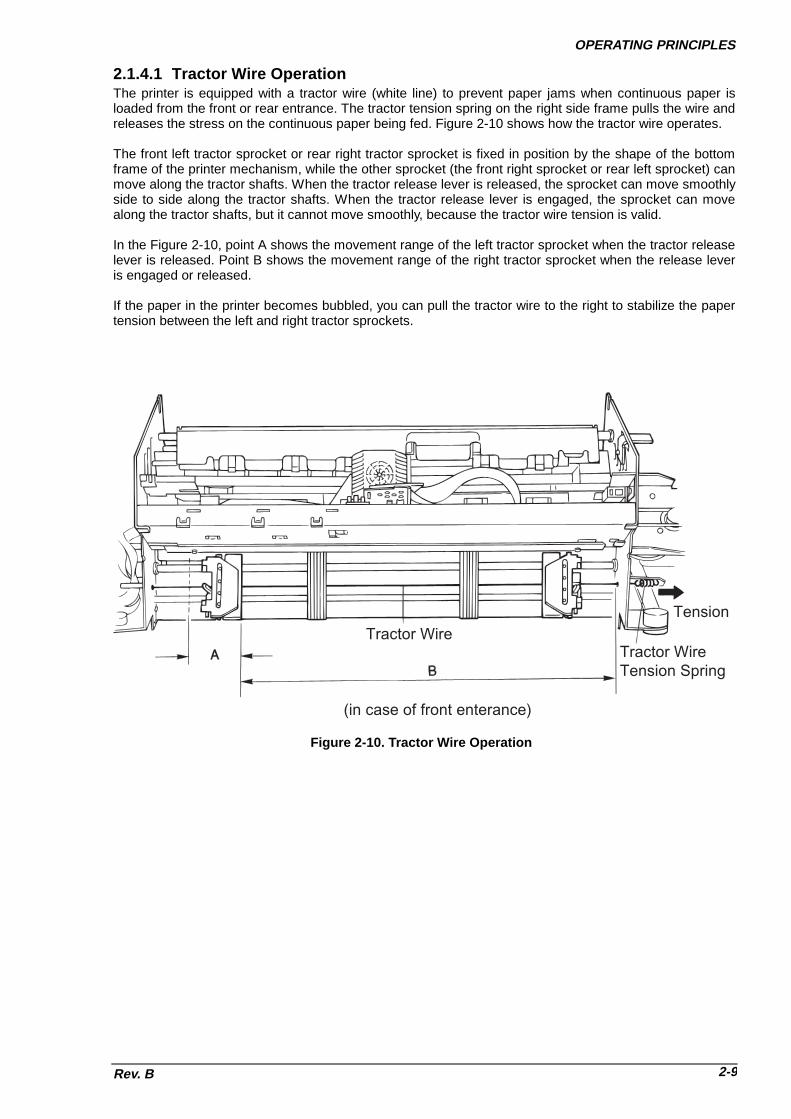
OPERATING PRINCIPLES
Rev. B 2-9
2.1.4.1 Tractor Wire OperationThe printer is equipped with a tractor wire (white line) to prevent paper jams when continuous paper isloaded from the front or rear entrance. The tractor tension spring on the right side frame pulls the wire andreleases the stress on the continuous paper being fed. Figure 2-10 shows how the tractor wire operates.
The front left tractor sprocket or rear right tractor sprocket is fixed in position by the shape of the bottomframe of the printer mechanism, while the other sprocket (the front right sprocket or rear left sprocket) canmove along the tractor shafts. When the tractor release lever is released, the sprocket can move smoothlyside to side along the tractor shafts. When the tractor release lever is engaged, the sprocket can movealong the tractor shafts, but it cannot move smoothly, because the tractor wire tension is valid.
In the Figure 2-10, point A shows the movement range of the left tractor sprocket when the tractor releaselever is released. Point B shows the movement range of the right tractor sprocket when the release leveris engaged or released.
If the paper in the printer becomes bubbled, you can pull the tractor wire to the right to stabilize the papertension between the left and right tractor sprockets.
(in case of front enterance)
Tractor WireTractor Wire Tension Spring
Tension
Figure 2-10. Tractor Wire Operation

DFX-8500
Rev. B2-10
2.1.5 Ribbon Feed and Tractor Select MechanismsThe RF motor supplies power to both the ribbon feed and tractor select mechanisms. The rotation of theRF motor pinion swings the ribbon feed select gear like a pendulum, using the lever axis as a supportpoint. The rotation of the RF motor is transmitted after the gears are engaged. When the RF motor piniongear rotates counterclockwise, the motor rotates the ribbon feed mechanism; when it rotates clockwise,the motor rotates the tractor select mechanism. ��Ribbon feed mechanism :Figure 2-11 shows the ribbon feed mechanism. The ribbon is fed in only one direction. Counterclockwiserotation of the RF motor is transmitted to the ribbon feed gear through the ribbon feed select gear andribbon feed transmission gear. The ribbon feed drive gear engages the winding roller on the ribboncartridge to feed the ribbon.
RF Select Gear RF Drive Gear
RF Transmission Gear
RF Motor
Ribbon Cartridge
Winding Roller
Figure 2-11. Ribbon Feed Mechanism

OPERATING PRINCIPLES
Rev. B 2-11
��Tractor select mechanism :Figure 2-12 shows the operation of the tractor select mechanism. Clockwise rotation of the RF motor istransmitted to the tractor select cam through the ribbon feed select gear and tractor select transmissiongear, and rotates the tractor select cam clockwise. The tractor select lever contacts the inside curve of thecam due to the spring force; when the cam rotates, the tractor select lever moves horizontally along thecurve.When the tractor select lever is set to the left, the tractor select gear engages the rear tractor assemblytrain, and the PF motor rotates the rear tractor assembly. When the tractor select lever is set to the right,the tractor select gear engages the front tractor assembly. The tractor Select sensor contacts the cam andcloses when it reaches the convex portion.The ribbon jam sensor is used to detect ribbon jam condition and to count ribbon life.
T r a c t o r D r i v e D e a r
T r a c t o r S e l e c t G e a rH o l d e r
T r a c t o r S e l e c t S e n s o r
R i b b o n F e e d S e l e c t G e a r
R F M o t o r
T r a c t o r S e l e c t C a m
T r a c t o r S e l e c t L e v e r U p p e r
T r a c t o r S e l e c t L e v e r L o w e r
T r a c t o r S e l e c t T r a n s m i s s i o n G e a r
T r a c t o r S e l e c tT r a n s m i s s i o n G e a r
C o n v e x
R i b b o n J a m S e n s o r R i b b o n F e e d G e a r
Figure 2-12. Tractor Select Mechanism

DFX-8500
Rev. B2-12
2.1.6 Plunger MechanismFigure 2-13 shows the plunger mechanism. The paper bail assembly is attached to the end of the plunger'siron core. The paper bail assembly axis is connected to the frame. When the plunger coil is energized, theforce of the paper bail spring returns the paper bail assembly to its original position.
Paper Bail ASSY. Lever
Plunger
Iron Core
Coil
Tension Spring
Figure 2-13. Plunger Mechanism

OPERATING PRINCIPLES
Rev. B 2-13
2.2 POWER SUPPLY OPERATIONThe printer can be powered by either of two power supply boards: the 120 V C204 PSB board or the 220/240V C204 PSE board. The only difference in the operation of these two boards is in the primary circuitry. Theysupply power to the printer in the same way. The power supply board outputs the DC current required to drivethe control circuits and printer drive mechanism. Table 2-1 shows the input voltages and fuse ratings of theboards and Table 2-2 shows the PSB/PSE board output specification.
Table 2-1. Power Supply Boards InputBoard Input Voltage Fuse RatingsC204 PSB board 120 VAC 12 A /125 VACC204 PSE board 220-240 VAC 6.3 A / 250 VAC
Table 2-2. Power Supply Board Output Specification+37 VDC Line +5V DC Line
Item VP1 VP2 VP3Rating Output Voltage +37.0 VDC +5.0 VDCAvailable OutputVoltage Fluctuation
35.5 - 37.5 VDC 4.75 - 5.25 VDC
Rating Output Current 1.5 A 2.0 AAvailable OutputCurrent Fluctuation
0.0 - 4.5 A*1) 0.0 - 5.0 A*1) 0.0 - 2.0 A
Over Current Protection Yes YesOver Current ProtectionReset Method
Turn the power switch off, then turn it again. Orcontrolled by C204 MAIN board with /PD signal.
Automatically recovered.
Short Circuit Current Less than 1.0 A Less than 1.0 AOver Voltage Protection Yes YesOver Voltage ProtectionReset Method
Turn the power switch off, then turn it again. Automatically recovered.
Over Voltage Limit Value 42 VDC 7 VDC*1): +37 V DC line Maximum in total is 13.0 A.

DFX-8500
Rev. B2-14
2.2.1 Power Supply OverviewFigure 2-14 shows a block diagram of the C204 PSB/PSE board.
FusePower SW.
AC Inlet
AC Source
Input FilterCircuit
RectifierCircuit
Surge Cut (at Power On)
SmoothingCircuit
+37V Line Switching 1/2
+37V Line Switching 2/2
SmoothingCircuit
PC101Power DownControl
+37V(VP1/VP2)
PC102
ConstantVoltageControl
Current LimitMonitoring
Over CurrentProtection
GP1
GP2
GP1
GP2
CL
PD
PC1Over VoltageProtection
+5V Regulator
SmoothingCircuit
PC201
ConstantVoltageControl
Current LimitMonitoring
+37V(VP3)
GP3
DRERR
Fan DriverGP3
FANDR
+5V Regulator Circuit +5V
GL
GP
GL
AbnormalCurrent (VP1/VP2)Monitoring
GP
VP3 DownMonitoring
SD
CN3
CN4
CN2
CN5
CN1
L
N
T1
T2 OvercurrentProtection
Figure 2-14. Power Supply Board Block Diagram

OPERATING PRINCIPLES
Rev. B 2-15
��General :The power supply board converts the AC input voltage to the DC voltages required to operate the printer. TheAC voltage is input to the AC inlet, and is supplied to the C204 PSB/PSE board via the power switch and afuse.Two main switching regulator circuits consist of two blocks, +37 V Lines ½ and 2/2. The one convert the ACvoltage to the +37 VDC specially for the print head coils drive requirement. The other convert the AC voltageto the +37 VDC for the printer mechanism drive power requirement (motors, solenoid, etc.) and for thesource of +5 V DC regulator circuit requirement (Refer to Table 2-3.).
��37V line block ½ :The generated +37 VDC is divided into two destinations; nine of the eighteen printhead pins (pins 1, 2, 7, 9,10, 11, 12, 15, and 17); the other to nine of the eighteen printhead pins (pins 3, 4, 5, 6, 8, 13, 14, 16 and 18).
��37V line block 2/2 :The generated +37 VDC is supplied to the motors and plunger on the printer mechanism, it also supplied tothe +5VDC regulator circuit and it output. +5V DC is supplied to the logic circuit on the main circuit.
��Cooling fan : The C204 PSB/PSE board includes a cooling fan that is driven by the +37 VDC. The fan lowers thetemperature of the PSB/PSE board circuit components, and it also lowers the CR motor temperaturebecause the motor locates on the way of an air exhaust channel of the fan.
Table 2-3. PSB/PSE Board Output DC VoltagesVoltage Board Application+37V (VP1-GP1) C204 DRV-B • Printhead drive ½+37 V (VP2-GP2) C204 MAIN • Printhead drive 2/2+37 V (VP3-GP3) C204 DRV • CR motor drive
• PF motor drive• PG motor drive• RF motor drive• HF drive• CR fan drive• Plunger drive• Optional Cutter’s motor drive
C204 PSB/PSE • Cooling fan on the PSB/PSE unit+5 V -GL C204 MAIN
C204 DRVC204 DRV-BC204 PNL
• All logic systems operating voltage• PF motor hold voltage• Plunger hold voltage• PG motor hold voltage• Power for all the sensors
VX-GL C204 MAINC204 DRVC204 DRV-B
• Voltage for power system pull-up. It is switchedby VXCNT signal of the CPU (IC2).
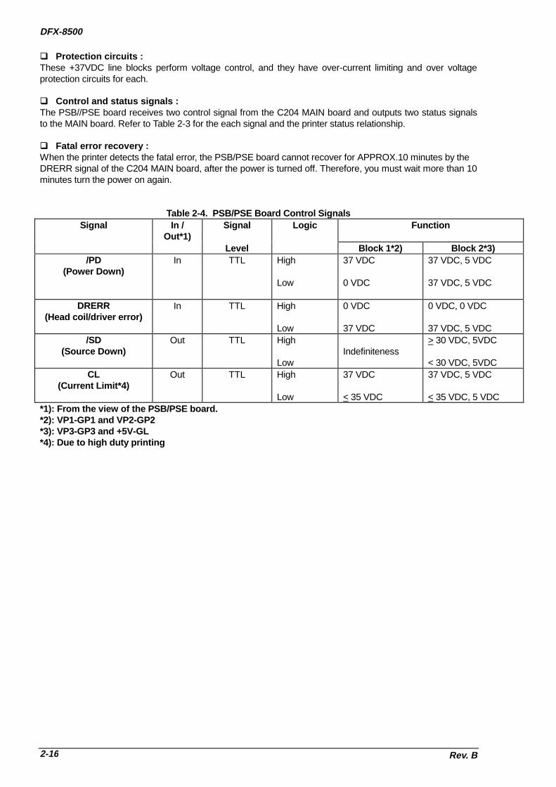
DFX-8500
Rev. B2-16
��Protection circuits :These +37VDC line blocks perform voltage control, and they have over-current limiting and over voltageprotection circuits for each.
��Control and status signals :The PSB//PSE board receives two control signal from the C204 MAIN board and outputs two status signalsto the MAIN board. Refer to Table 2-3 for the each signal and the printer status relationship.
��Fatal error recovery :When the printer detects the fatal error, the PSB/PSE board cannot recover for APPROX.10 minutes by theDRERR signal of the C204 MAIN board, after the power is turned off. Therefore, you must wait more than 10minutes turn the power on again.
Table 2-4. PSB/PSE Board Control SignalsSignal In /
Out*1)Signal Logic Function
Level Block 1*2) Block 2*3)/PD
(Power Down)In TTL High
Low
37 VDC
0 VDC
37 VDC, 5 VDC
37 VDC, 5 VDC
DRERR(Head coil/driver error)
In TTL High
Low
0 VDC
37 VDC
0 VDC, 0 VDC
37 VDC, 5 VDC/SD
(Source Down)Out TTL High
LowIndefiniteness
> 30 VDC, 5VDC
< 30 VDC, 5VDCCL
(Current Limit*4)Out TTL High
Low
37 VDC
< 35 VDC
37 VDC, 5 VDC
< 35 VDC, 5 VDC*1): From the view of the PSB/PSE board.*2): VP1-GP1 and VP2-GP2*3): VP3-GP3 and +5V-GL*4): Due to high duty printing

OPERATING PRINCIPLES
Rev. B 2-17
2.3 CONTROL CIRCUITFigure 2-15 shows a block diagram of the control circuit with the C204 MAIN board at the center.
2.3.1 Control Circuit Operation OverviewThe core of the control circuit is the TMP95C061AF CPU (IC2). This CPU is driven using a 24.57 MHzexternal clock (CRU1). The CPU executes programs stored in the PROM (IC5). The CPU starts executing aprogram upon receiving the reset signal from an external device (IC13) via the gate array E05B36 (IC1). TheCPU accesses the internal RAM and external RAM (IC14). The CPU also controls the EEPROM (IC11) usedto store the parameters, such as the tear off position, while the printer is turned off.
The CPU controls all the printer operations via the peripheral IC E05B36 (IC1) and controls the printermechanism. The main functions of the E05B36 (IC1) are: /CS (Chip Select) signal creation, addressdecoding, printhead driver control, carriage driver control, encoder pulse circuit control, PG and HF phasesignal creation, interface control, CR and PF motor driver abnormal sensor circuit monitoring, reset signalcreation, control of the PSB/PSE board, control of the panel unit, and reading the DIP switch settings on theC204 SUB board.
Signals, such as DRERR (driver error) and PD (power down), are connected to the C204 PSB/PSE board toprovide back-up control of the EEPROM (when the printer is turned off) and control of the power supplyvoltage. When the POFF signal informs the CPU that the power has been turned off (or CL that the powersupply voltage has dropped), the CPU turns off the power supply voltage of the C204 PSB/PSE board byoutputting the PD signal.The reset circuit outputs the reset signal when the printer is turned on or off, the voltage level drops, or areset signal is input from an external device. It resets the control circuit for a certain period directly or via theE05B36.

DFX-8500
Rev. B2-18
PrintheadDrive Circuit 2/2
PrintheadDrive Circuit 1/2
Control & Monitoring
+37 VDC,+5 VDC
PrintheadTemperature
Paper Width
PG Encoder
PE Signals(Front, Rear, Top)
Paper Jam
Pull Tractor
Tractor Select
Head FanTemperature
Current Monitoring
CR MotorInsulation
PSB/PSE Board
OptionCutter
Panel Unit
Reset IC (IC13)IE
EE
12
84
I/F
ABDB
Control
G/AE05B36 (IC1)
ENCA,ENCB
CRCLM
PG MotorDrive Circuit
CR MotorControl & DriveCircuit (IC1, IC3)
CRINS
PF MotorDrive Circuit (IC2)
RF MotorDrive Circuit
ABDB
Control
OptionalType-B I/FCard
P-ROM (IC5)
RAM (IC14)
Level Converter (IC9)
Se
rial I/F
EEPROM (IC11)
24.57MHz (CRU1)
HPSENS,HNSENS
CPUTMP95C061 (IC2)
Printhead 2/2
Printhead 1/2
Cover OpenSensor`
DRV-B Board
DRV Board
RF Motor
PF Motor
Interlock SW.
CR MotorCR Encoder
PG Motor
Plunger DriveCircuit
Head Fan Drive Circuit
Fan Drive Circuit
Fan
Head Fan
Plunger
HD
PG
CR
PGENCA,PGENCB
Ribbon Jam
PLG
HFTMP
PWIDTH
HTMP
RF
PF
TXD/RXD
DTR/CTS
POFF
CL,PD,DRERR
LED,SW
RESET,RSTOUT,ERRCRPFX
PFA
FAN
MAIN Board Mechanism
19.55MHz (CRU2)
SUB Board
SWITCH
SWCNT
(DIP SWs)
PG Home
PDATA1-8,/STB,/ACK, BUSY
Figure 2-15. Control Circuit Block Diagram

OPERATING PRINCIPLES
Rev. B 2-19
Table 2-5 describes the functions of the main components on the C204 MAIN and C204 DRV board.
Table 2-5. Main IC FunctionsBoard IC Name Location FunctionsC204 MAIN TMP95C061
(CPU)IC2 Receives data from the host computer via the gate array, loads
the data to the input buffer in the RAM, and converts the imagedata to print data.
E05B36(Gate Array)
IC1 The main features are:• /CS (Chip Select) signal creation• Address decoding• Address latching• Clock pulse creation• Printhead driver control• CR motor driver control• CR and PG motor pulse encoder I/O (input/output)• Encoder pulse I/O• Phase signal creation for the motors• I/O port control• Interface control• Abnormal CR and PF motor detection• /RESET signal creation
PROM IC5 Contains the program that runs the CPU.RAM IC14 Holds the CPU working area and buffers (input,, line,, and
image buffers).EEPROM IC11 Memorizes the printer unique parameter during the power is off.ADM232 IC9 EIA to Logic level voltage level converterPST591D IC13 System reset IC
C204 DRV STK681-050 IC1 Drives the CR motor.STK67138MK4 IC2 Drives the PF motor.uPC393C IC3 Detects the current in the CR motor driver and feeds it back to
the gate array on the C204 MAIN board.

DFX-8500
Rev. B2-20
Figure 2-16 shows the data flow for data input via the parallel interface. Although various circuits performdata processing, the control core is the CPU and all operations are executed via the CPU. In this circuit, theE05B36 IC (IC1) provides the interface between the external host computer and the CPU, and all dataprocessing is performed by read/write operations to MMIO (Memory Mapped Input / Output).Data from the host computer is latched by repeating steps 1 through 3 below.
1. Upon receiving the /STROBE pulse, IC1 latches the data into ports PDATA 1 - 8 and sets the BUSYsignal to HIGH.
2. The CPU reads the latched data from the MMIO port, checks whether the data is a print command (CRcode), and stores it in the input data buffer if it is not.
3. After checking the data, the CPU makes IC1 clear the BUSY signal and output the /ACKNLG signal, viathe MMIO accesses. When either a CR code is received or the input data buffer becomes full, the CPUsets the BUSY signal to HIGH and executes printing.
4. The CPU reads the data from the input data buffer, analyzes each byte to determine whether it is acharacter or a command, and converts it to print data. The print data consists of 1-byte character codesand 2-byte attributes. Character data is stored as character codes and commands or character types arestored as attributes.
5. The print data is stored in the line buffer in units of one line of data.6. The CPU reads the print data stored in the line buffer byte by byte, accesses the CG (Character
Generator), and expands the data in the image buffer (in the case of download characters, in thedownload CG). A row of expanded data is output to the printhead control circuit as printhead data.
Note : The data flow from the Type-B I/F card is the same as the data flow from the parallel interface, described above, except the signal names and data access method differ.
MMIO
CR command ?
/STROBE
DATA
BUSY, /ACK
3
1 2
E05B36 (IC1) CPU (IC2)
DATA
No
Yes
DATABuffer full ?
Yes
RAM (IC3)
Input Data Buffer
CPU (IC2)
4
5Line Buffer
Command Analyzer
Attribute
Character Gnerator
Down Load
Image Buffer
68
7E05B36
Controls printer mechanism.
STBINT
Figure 2-16. Parallel Interface Data Flow

OPERATING PRINCIPLES
Rev. B 2-21
2.3.2 Reset CircuitThis section describes the hardware reset circuit. When the hardware reset signal is input, all ICs in thecontrol circuit are reset, and the CPU executes the program from the starting address. Figure 2-17 shows thereset circuit block diagram.The circuit is equipped with a reset IC: PTS591(IC13) is used for resetting the + 5 VDC line. The resetoperation is described below.
��Power On/Off Reset:Reset IC PTS591 (IC13) monitors the +5 VDC line on the C204 MAIN board. If it drops to 4.2 VDC orsmaller, the reset IC outputs a LOW signal to the CPU (IC2) and E05B36 (IC1) gate array.
��Forced Reset:The gate array outputs the RSTOUTX or ERRCRPFX signals to the XRESET of the CPU, and also to thegate array itself.
��/INIT Signal Reset:When the gate array receives the /INIT signal from the host computer, the signal is transferred to the INT4 ofthe CPU, then CPU performs the /INIT reset operation.
+5
1
30
XRESET
/RESETX
/RSTOUTX
Type-B, Parallel I/F /INIT signal
E05B36 (IC1)
CPUTMP95C061 (IC2)
PST591 (IC13)
R218
C52
/ERRCRPFX
R215
C56
113
112
111INITRQ
100
INT436
3
VOUTVCC
Figure 2-17. Reset Circuit Block Diagram

DFX-8500
Rev. B2-22
2.3.3 Sensor CircuitsFigure 2-18 shows the sensor circuits in block diagram form. The printer is equipped with the followingsensors:
1. Front and rear PE sensors (use a photo interrupter)2. Top PE sensor (to detect the TOF position, uses a photo interrupter)3. Paper jam sensor (uses a magnetic transistor)4. Tractor select sensor (uses a micro mechanical switch)5. Pull tractor sensor (uses a micro mechanical switch)6. CR encoder sensor (uses a photo interrupter)7. PG encoder sensor (uses a photo interrupter)8. PG home sensor (uses a micro mechanical switch)9. Ribbon jam sensor (uses a photo interrupter)10. Cover open sensor (uses a micro mechanical switch)11. Printhead temperature sensor (uses a thermistor)12. Head fan temperature sensor (uses a thermistor)13. Paper width sensor (uses a photo reflector)14. CR motor isolation resistance sensor (monitored by the analog port of the CPU)15. PSB/PSE board power off sensor (signal interface)
E05B36 (IC1)
CN4ENCA
ENCB CR Encoder
3
4
CN14
PGENCA
PGENCB
35
34
148
149
ENCA
ENCB
PGENCA
PGENCB
28
25
CN14
CPUTMP95C061 (IC2)
AN
0
AN
1
AN
2
AN
3
202122 23
Prin
the
ad
Te
mp
era
ture
He
ad
Fa
n T
em
pe
ratu
re
CR
Mo
tor In
sula
tion
Pa
pe
r Wid
th
INT
5
35
Co
ver O
pe
n
CN3
1
CN1
221929
Tractor Select
Pull Tractor
28
29
TRSEL
PTRCT
19
20
Paper Jam
Front PE
30
31PJAM
FPE
21
22
Rear PE
Top PE
32
33RPE
TPE
23
24
PG Home
Ribbon Jam37
RBJAM29
3618PG Home
18
CN10
XN
MI
10
PO
FF
(SD
)
8
Figure 2-18. Sensor Circuit Block Diagram

OPERATING PRINCIPLES
Rev. B 2-23
Each sensor is described below.
1. Front and rear paper end sensors��Detection form: Photo interrupter��Output form: Open collector (pulled up to 10 K ohms resistor)��Logical: Paper present: LOW
Paper out: HIGH
2. Top paper end sensor (to detect the TOF position)��Detection form: Photo reflector��Output form: Open collector��Logical: Paper present: LOW
Paper out: HIGH
3. Paper jam sensor��Detection form: Magnetic transistor��Output form: Rectangle wave (1 channel, TTL level)��Logical: Paper feed: Level changes continuously.� Paper jam: Level remains the same.��Supplement: The magnetic transistor is attached to the tension roller on the paper tension unit.
4. Tractor select sensor��Detection form: Micro mechanical switch��Logical : Front tractor: LOW (closed)
Rear tractor: HIGH (open)
5. Pull tractor sensor��Detection form: Micro mechanical switch��Logical : Pull tractor installed: LOW (closed)
Pull tractor not installed: HIGH (open)
6. Carriage encoder sensor��Detection form: Photo reflector��Transaction: Rectangle wave, A and B phases respectively.
7. Platen Gap encoder sensor��Detection form: Photo interrupter��Output form: Rectangle wave, 2 channel��PG ability: T = 0.015 mm / pulse��Available range: 0 < T < 0.7 mm
8. Platen Gap home position sensor��Detection form: Micro mechanical switch��Logical:: Home: LOW (closed)
Out of home: HIGH (open)
9. Ribbon jam sensor��Detection form: Photo interrupter��Function: : The main board monitors signal change during ribbon feed.
10. Cover open sensor��Detection form: Micro mechanical switch��Logical:: Cover closed: LOW
Cover open: HIGH
11. Printhead temperature sensor (uses a thermistor) The thermistor is included on the printhead.
12. Head fan temperature sensor (uses a thermistor)The thermostor is included on the head fan.

DFX-8500
Rev. B2-24
13. Paper width sensor��Detection form: Photo reflector��Output form : Emitter follower��Judgemwnt : No paper present: Standard voltage level.
Paper present: The voltage level is double the standard voltage level.
14. CR motor isolation resistance sensor (monitored by port AN2 of the CPU)To provide information about the CR motor life, the analog port (AN2) of the CPU checks the isolationresistance every time the printer is turned on. If the isolation resistance is equal or less than 2.2 K ohms, acarriage error is detected and the printer beeps.
15. PSB/PSE Board power off sensor (signal interface)When the +37 VDC line voltage drops, the PSB/PSE board sends a HIGH POFF signal to the C204 MAINboard.

OPERATING PRINCIPLES
Rev. B 2-25
2.3.4 CR Motor Drive CircuitFigure 2-19 shows the internal circuit for the CR motor,Table 2-6 provides the CR motor specification, andFigure 2-20 shows a block diagram for the CR motor drive circuit.An STK681-050 (IC1) bipolar driver IC drives the CR motor. It has built-in bipolar switching transistors and acurrent limiter. A comparator IC uPC393C (IC3) monitors the current in the CR motor driver IC (IC1). If thecurrent exceeds the set value, it is fed back to the gate array (E05B36), and then the gate array outputs thesignal for the current setting transistors (Q5, Q6, and Q7).When the printer is turned on, CPU analog port AN2 measures the isolation resistance in the CR motor. If theisolation resistance is equal or less than 2.2 K ohms, the printer change the status to the carriage error.If the printer cover is open during power on, the CR motor driver power is cut by the interlock switch.The ENCA pulse that the carriage encoder outputs is input to general purpose port CRENCA of the gatearray, and the ENCB pulse that the carriage encoder outputs is input to general purpose port CRENCB of thegate array. The gate array counts these pulses using the internal counter and determines the amount anddirection of motor rotation.
Table 2-6. CR Motor SpecificationsSpecification Description
Form DC servo motorSupply Voltage 37 VDCInternal CoilResistance
1.66 ohms (+ 10 %)
CurrentConsumption*1)
Accerelation / Deceraration:4.6 A (AV.)
Constant Speed:2.5 A (AV.)
*1): at Super draft printing, + 10 %
Motor
Q2
Q3Q1
Q4
VP3 (+37 VDC)
GP3 (GND)
R1
Figure 2-19. CR Motor Internal Circuit
E05B36 (IC1)
CRAX
STK681-050(IC1)
IN_A
VP3
VCC1
OUT1
CR B
Vref
ZD14.3 V
A OUT
AIN+
AIN-
CR
I0
CR
I1
CR
I2C
RE
NC
B
CR
EN
CA
VCC1
OUT2
CR A
IN_B
IN_C
IN_D
DRV Board
MAINBoard
CRCLK
Q16,Q17,Q18,Q19
VX
CRBXCRCXCRDX
CLK
Q34,Q35,ZD2
VX
CR
CL
M
Q5,Q6,Q7
GPGP
Vref
+5V
GP3
GP3
Vx
CPUTMP85C061 (IC2) AN2
CRINS
CRCLM
D3
uPC393C(IC3)
Partical PressureCircuit
Interlock SW
Carriage Motor
Carriage Encoder Sensor
ENCA
ENCB
Figure 2-20. CR Motor Drive Circuit Block Diagram

DFX-8500
Rev. B2-26
Table 2-7 lists the CR motor drive modes.
Table 2-7. CR Motor Drive ModesDivision Drive Mode CR Motor Speed
(rpm)Acceleration /
Deceleration ControlCurveNote1)
ConstantSpeedControl
Carriage moves Super Draft 2800 Acceleration and PI controlwith printing. Super Draft HD 2666 Deceleration 1Note 2) Draft 2100
Draft HD 2000Bit image 1 1050 Acceleration andBit image 2 1050 Deceleration 3Bit image 3 1050NLQ 1050NLQ HD 1000Super Draft X 1/3 888Bit image 4 933Draft X 1/3 666Bit image 1 X 1/3 555Bit image 2 X 1/3 500Bit image 3 X 1/3 444NLQ X 1/3 333Draft X 1/6 333Bit image 4 X 1/3 277Bit image 3 X 1/6 222
Carriage moveswithout printing
Home positionseek
500
Note 3) Paper widthdetection seek
500
Logical seek 0 2100Logical seek 1 1050Logical seek 2 333Measurement seek -
Notes 1: Refer to Table 2-8.Notes 2: This division applies to all printing modes. PI control oversees the constant speed. (Refer
to page 2-27 for more information on PI control.) For increased throughput, the divisionSuper Draft to Draft HD allows printing during acceleration and deceleration.
Notes 3: This division increases throughput when the carriage is moving and the printer is notprinting.
The printer has three deceleration control modes. The degree of deceleration is determined by how the CRmotor transistors are driven. Table 2-8 describes how the transistors are driven for each mode.
Table 2-8. CR Motor Drive SequenceCarriage Transfer Direction Driving Mode Driver (Refer to Figure 2-19.)
Q1 Q2 Q3 Q4Acceleration ON ON
Left -> Right Deceleration 1 ON ONDeceleration 2Deceleration 3 ON ONAcceleration ON ON
Right -> Left Deceleration 1 ON ONDeceleration 2Deceleration 3 ON ON

OPERATING PRINCIPLES
Rev. B 2-27
��PI Control :PI control keeps the CR motor speed constant using the encoder pulses ENCA and ENCB with the gatearray E05B36. The E05B36 generates the PWM (pulse width modulation) signal according to the CR motorspeed to the PWM port of the gate array and determines the duty of the carriage drive timing.CR ports I0, I1,and I2 output the drive signal for the CR motor.
��Acceleration control :Until the carriage speed reaches the constant speed set by PI control, acceleration control determines thespeed of the carriage. The printer can print while the carriage is accelerating. The carriage speed moves toconstant control speed smoothly to prevent the CR motor from exceeding the constant control speed. TheE05B36 gate array controls the motor driver (STK681-050), which performs the current chopping. Figure2-21 shows the acceleration control curve.
Speed 0 - SP1
1. It causes the carriage to accelerate.2. Because the control circuit measures time periods with the encoder signal, when the carriage speed
reaches SP1, it changes to the next sequence (SP1 - SP2).
SP1 - SP21. When the carriage speed reaches SP1, the printer uses the acceleration driving mode, based on the duty
data, and the rest of the time, it uses Deceleration driving mode 2.2. During this time the control circuit measures time periods using the encoder signal, and controls the
following:• When duty data becomes Dutymin before the carriage speed reaches SP2. Then, when the carriage
speed reaches SP2, the next sequence (SP2-) takes effect.• When the carriage speed reaches SP2 before duty data becomes Dutymin, the next sequence (SP2-)
takes effect.
SP2 -When the carriage speed reaches SP2, PI control oversees the carriage speed.
0
SP1
SP2
SPref
Acceleration
Deceleration 2
Co
ntr
ol S
ign
al
Constant Speed Control
Acce
lera
tion
Curv
e
Figure 2-21. CR Motor Drive Circuit Block Diagram

DFX-8500
Rev. B2-28
��Deceleration control:Deceleration control provides smooth deceleration and prevents rapid vibration.The duty data for deceleration control is determined for each printing mode. Pulse width modulation (PWM)determines each printing mode.
Current speed - SP31. The printer uses Deceleration driving mode 2, based on the duty data, and the rest of the time, it uses
Deceleration driving mode 1.2. During this time the control circuit measures time periods using the encoder signal, and controls the
following:• When duty data becomes Dutymin1 before the carriage speed reaches SP3.• When the carriage speed reaches SP3 before duty data becomes Dutymin1, the next sequence (SP3 -
Speed 0) takes effect.
SP3 - Speed 01. When the carriage speed reaches SP3, Deceleration driving mode 3 takes effect. This control method is
the inverse-continuity break method.2. During this time, the control circuit measures time periods using the encoder signal. When the rising
edge of next pulse is not detected after 1.5 seconds, Deceleration driving mode 1 takes effect and thecontrol circuit controls short-break.
0
SPref
SP3
Deceleration 2 or Deceleration 1
Co
ntr
ol S
ign
al
PWM Perodic Time
1 2 3
Deceleration 3
De
cele
ratio
n C
urv
e
Note: 1, 2, and 3 indicate the PWM control section number.
Figure 2-22. CR Motor Drive Circuit Block Diagram

OPERATING PRINCIPLES
Rev. B 2-29
2.3.5 PF Motor Drive CircuitStepping motor driver STK6713BMK4 (IC2) drives the PF motor. Figure 2-22 shows the PF motor drivecircuit block diagram, and Table 2-9 provides the PF motor specifications.
Table 2-9. PF Motor SpecificationsSpecification Description
Form 4-phase, 200-pole, HB* pulse motorSupply Voltage 37 VDC (applied to the drive circuit)Internal Coil Resistance 2.8 ohms + 10 % per phase at 25 oCFrequency 4274 pps** (normal mode,, constant driving): 9.9 ips***
2610 pps (middle speed mode,, constant driving): 6 ipsCurrent Consumption Driving: 1.75 A, + 0.20 A per phase (average)
Holding: 0.26 A, + 0. 2 A per phase (average)*HB …. Hybrid**pps …. pulses per second***ips …. inches per second
The motor pulse switching signals are transmitted from CPU ports PG00 to PG03. The PF motor iscontrolled using open-loop phase switching based on the specified time data, and the phase driving methodis 1-2 phase excitation. (When the PF motor is held, the phase driving method is 1 phase excitation.) TheCPU selects the most suitable driving mode from the modes below according to conditions such as thepaper feed length and the pull tractor condition.
��Micro feed (adjust) mode : < 20 / 432 inches��Middle speed mode: > 20 / 432 inches and < 60 / 432 inches, or with optional pull tractor��Normal speed mode: > 60 / 432 inches
Each phase switching FET in driver IC2 is an open collector. When the phase switching data is HIGH, themotor is turned on. The PFA port of the gate array monitors the phase A signal of the PF motor and checkswhether it is operating normally. The PFA port is used as the WDT (watch dog timer).If PF motor operation is abnormal, the gate array outputs the /RSTOUT (reset request) signal to the systemreset IC (IC13). Refer to Section 2.3.2 Reset Circuit.
STK6713B (IC2)
PF A
PF B
PF C
PF D
OUT_A
OUTXA
OUT_B
OUTXB
CPU TMP95C061A (IC2)
PFH/R
PG00
PG01
PG02
PG03
VR
EF
VR
EF
PFA
+5V
GP3
4.3 VDC
Ref. Voltage Setting Circuit (Q9)
IN_A
INXA
IN_B
INXB
GP3
SG
GP
Gate Array E05B36 (IC1)
Vref
PF COM
VP3
DRV Board
MAINBoard
Figure 2-23. PF Motor Drive Circuit Block Diagram
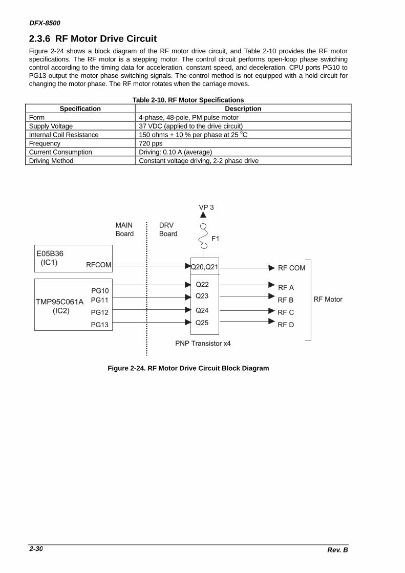
DFX-8500
Rev. B2-30
2.3.6 RF Motor Drive CircuitFigure 2-24 shows a block diagram of the RF motor drive circuit, and Table 2-10 provides the RF motorspecifications. The RF motor is a stepping motor. The control circuit performs open-loop phase switchingcontrol according to the timing data for acceleration, constant speed, and deceleration. CPU ports PG10 toPG13 output the motor phase switching signals. The control method is not equipped with a hold circuit forchanging the motor phase. The RF motor rotates when the carriage moves.
Table 2-10. RF Motor SpecificationsSpecification Description
Form 4-phase, 48-pole, PM pulse motorSupply Voltage 37 VDC (applied to the drive circuit)Internal Coil Resistance 150 ohms + 10 % per phase at 25 oCFrequency 720 ppsCurrent Consumption Driving: 0.10 A (average)Driving Method Constant voltage driving, 2-2 phase drive
TMP95C061A (IC2)
PG10
PG11
PG12
PG13
Q22
Q23
Q24
Q25
PNP Transistor x4
RF A
RF B
RF C
RF D
MAINBoard
DRVBoard
E05B36 (IC1) RFCOM Q20,Q21
VP 3
F1
RF COM
RF Motor
Figure 2-24. RF Motor Drive Circuit Block Diagram

OPERATING PRINCIPLES
Rev. B 2-31
2.3.7 PG Motor Drive CircuitFigure 2-25 shows a block diagram of the PG motor drive circuit, and Table 2-11 provides PG motorspecifications.The PG motor is a stepping motor. The motor phase switching signals are output from the E05B36 portsPGA to PGD. The motor common voltage (PGCOM) alternates between drive mode (+37 VDC) and holdmode (+5 VDC) using the PG H/R signal of E05B36. The phase driver circuit is made by discrete transistorsQ12 to Q15.The phase A output pulse from the platen gap encoder (ENCA) is input to port ENCA of E05B36 and thephase B output pulse from the platen gap encoder (ENCB) is input to port ENCB of E05B36. The E05B36counts these pulses using the internal counter and determines the amount and direction of motor rotation.
Table 2-11. PG Motor SpecificationsSpecification DescriptionForm 4-phase, 48-pole, PM pulse motorSupply Voltage 37 VDC (applied to the drive circuit)Internal Coil Resistance 250 + 18 ohms per phase at 25 oCCurrent Consumption Driving: 0.20 A (average)
Holding: 0.02 A + 5 mAFrequency 285 ppsDriving Method Constant voltage driving, 2-2 phase drive
PG H/R
PG A
PG
A
PG
B
PG
C
PG
D
PG
EN
CA
Plsten GapEncoder
PG Motor
PG
CO
M
E05B36 (IC1)
Q12,Q13,Q14.Q15
VP 3
F2
Q10,Q11
D10
+5V
DRV BoardMAIN Board
PG B
PG C
PG D
PG
EN
CB
Figure 2-25. PG Motor Drive Circuit Block Diagram

DFX-8500
Rev. B2-32
2.3.8 Plunger Drive CircuitFigure 2-26 shows a block diagram of the plunger drive circuit, Table 2-12 provides the plunger specification,and Table 2-13 provides the plunger switching pattern.The plunger is driven using three switching patterns. Gate array E05B26 ports PLP and PLN output theplunger coil drive signals. When the PNP port of the gate array turns on switching transistors Q30 and Q31are turned on and the supply voltage (VP3) flows into the plunger coil. When switching transistor Q30 isturned off, Q31 is turned off and the hold voltage (+5 V) flows into the plunger coil via Q32, using the portPLN of the E05B36.
Table 2-12. Plunger SpecificationsSpecification DescriptionForm DC solenoidSupply Voltage 37 VDC (applied to the drive circuit)Internal Coil Resistance 9 ohms + 5 % at 25 oCCurrent Consumption Driving: 3.7 A (MAX.)
Holding: 0.4 A
Table 2-13. Plunger Switching PatternSuspension Roller Status Q30 and Q31 Q32
Closed Off OffClosed -> Opened On Off
Closed with holding voltage Off On
Q30
E05B36 (IC1)
PLPP
LN
E
CB
NPN
Q31
PNPB
C
Plu
ng
er C
oil
GP3
Q32
EB
C
VP 3
F3
Figure 2-26. Plunger Drive Circuit Block Diagram

OPERATING PRINCIPLES
Rev. B 2-33
2.3.9 Printhead Drive CircuitFigure 2-27 shows a printhead drive circuit block diagram.
��General :The print data lines from IC1 are active when they are HIGH. When ports HDR1 (HDL1) to HDR9 (HDL9)of IC1 go HIGH, the FET gates are biased, and the FETs are turned on to apply the current to theprinthead coil. At the same time, ports HDRS1 (HDLS1) to HDRS9 (HDLS9) of IC1 go HIGH, the FETgates are biased, and the FETs are turned on because the each printhead coil is driven by bipolar drivemethod. When the HD port of IC1 goes LOW, the FET is turned off and the printhead coil current is cut.
Two +37 VDC lines (VP1-GP1 on the C204 DRV-B board and VP2-GP2 on the C204 MAIN board) assignthe common voltage for the printhead coil. Pins #1, #2, #7, #9, #10, #11, #12, #16, and #17 are suppliedby the VP2-GP2 line (CN1 on the C204 MAIN board). Pins #3, #4, #5, #6 #8, #13, #14, #15, and #18 aresupplied by the VP1-GP1 line (CN1 on the C204 DRV-B board).
The CPU monitors the printhead temperature and head fan (HF) temperature. When the temperaturerises abnormally, printing stops at once until the temperature cools.The CPU also monitors the printhead driver status, P-channel and N-channel FET respectively. If theprinthead driver FET shorts, CPU (IC2) port PDRERR (P-channel) / NDRERR (N-channel) detects HIGHlevel and the E05B36 (IC1) sends the DRERR (Driver Error) signal to the C204 PSB/PSE board. Whenthe C204 PSB/PSE board receives this signal, it stops the output voltage and the printer beeps.
E05B36 (IC1)
FANA
Q10
Q11
HFANA
HFANBFANAX
HD
RS
1-H
DR
S9
HD
R1
-HD
R9
HD
LS
1-H
DLS
9
HD
L1-H
DL9
Printhead Driver Circuit 1/2
Printhead Coils 1/2 DRV-B Board Printhead Driver Circuit 2/2 Printhead Coils 2/2
MAIN Board
VX VP1 GP1 VX VP2 GP2
GP2
VP2
R100
R101
ND
RE
RR
GP2
R98
R99
ZD4
ZD1
PD
RE
RR
TMP95C061A (IC2)
Monitoring PNPs Short Circuit
Monitoring NPNs Short Circuit
24V5.1V
Printhead Thermistor
HN
SE
NS
HPSENSHTMP
HF Motor ThermistorFTMP
HT
MP
FT
MP
HF Motor
Figure 2-27. Printhead Drive Circuit Block Diagram

DFX-8500
Rev. B2-34
��Printhead high temperature feedback operation :The printer supports the printhead temperature detection sequence, which consists of the following steps:
1. When the printhead temperature is less than 110 oC, the printer performs normal printing.2. When the printhead temperature exceeds equal or more than 110 oC, the printer performs interval printing
(Carriage rest time at the sides is little bit longer than the normal.)3. When the printhead temperature exceeds equal or more than 120 oC, the printer stops printing until the
temperature goes down to 100 oC or less.4. When the printhead temperature returns less than 100 oC, the printer performs normal printing again.
��HF temperature feedback operation :The printer supports the printhead fan (HF) temperature detection sequence, which consists of the followingsteps:
1. When the printhead fan temperature is less than 65 oC, the HF fan stops.2. When the printhead fan temperature exceeds equal or more than 65 oC, the HF rotates.
3. When the printhead temperature goes down to 50 oC or less, the HF stops again.

CHAPTER 3DISASSEMBLY AND ASSEMBLY
3.1 OVERVIEW ............................................................................................................3-1 3.1.1 Precautions for Disassembly and Assembly ....................................................................... 3-1
3.1.2 Tools ................................................................................................................... ..................... 3-3
3.1.3 Specification for Screws................................................................................................ ........ 3-5
3.1.4 Service Checks After Repair............................................................................................. ..... 3-6
3.2 DISASSEMBLY AND ASSEMBLY .........................................................................3-7 3.2.1 ROM Replacement......................................................................................................... ......... 3-8
3.2.2 Printhead and Ribbon Mask Assembly Removal ................................................................ 3-9
3.2.3 Housing Removal ......................................................................................................... ........ 3-13 3.2.3.1 Top Cover Removal................................................................................................. 3-13 3.2.3.2 Left, Right, and Front Covers Removal and Fuse Replacement............................. 3-14 3.2.3.3 Front Panel Unit Removal ....................................................................................... 3-16 3.2.3.4 Upper Case Removal .............................................................................................. 3-17
3.2.4 Circuit Boards Removal.................................................................................................. ..... 3-18 3.2.4.1 Bottom Panel Assembly Removal ........................................................................... 3-18 3.2.4.2 Cooling Fan and C204 Power Supply Board Unit Removal .................................... 3-21 3.2.4.3 C204 SUB Board Unit Removal .............................................................................. 3-22 3.2.4.4 C204 DRV-B and C204 DRV Board Units Removal ............................................... 3-23 3.2.4.5 C204 MAIN Board Unit Removal............................................................................. 3-24 3.2.4.6 AC Inlet Removal .................................................................................................... 3-26 3.2.4.7 C204 PNL Board Removal ...................................................................................... 3-27
3.2.5 Interlock Switch and Cover Open Sensor Assembly Removal ........................................ 3-28
3.2.6 Printer Mechanism Removal............................................................................................... . 3-29 3.2.6.1 Fan Removal ........................................................................................................... 3-31 3.2.6.2 Ribbon Feed Change Lever Unit Removal.............................................................. 3-32 3.2.6.3 Tractor Select Lever (Upper and Lower) Assembly Disassembly ........................... 3-34 3.2.6.4 Ribbon Jam Sensor Removal.................................................................................. 3-35 3.2.6.5 Connector Junction Board Assembly and FPC Board Assembly Removal............. 3-36 3.2.6.6 PG Sensor and PG Motor Removal ........................................................................ 3-37 3.2.6.7 Plunger and Paper Bail Assembly Removal............................................................ 3-38 3.2.6.8 Upper Paper Guide and Top PE Sensor Removal .................................................. 3-40 3.2.6.9 Tension Roller Shaft Removal ................................................................................. 3-41 3.2.6.10 Platen Removal ..................................................................................................... 3-43 3.2.6.11 Paper Jam Sensor Removal .................................................................................. 3-44 3.2.6.12 Pull Tractor Sensor Removal................................................................................. 3-45 3.2.6.13 Paper Width (PW) Sensor Removal ..................................................................... 3-46 3.2.6.14 PG Home Sensor Removal .................................................................................... 3-47 3.2.6.15 PF Motor Removal ................................................................................................. 3-49 3.2.6.16 Left Side Frame Gear Removal ............................................................................ 3-50 3.2.6.17 Front Tractor Assembly Removal ........................................................................... 3-51 3.2.6.18 Rear Tractor Assembly Removal .......................................................................... 3-52 3.2.6.19 CR Motor Fan Removal.......................................................................................... 3-53 3.2.6.20 CR Motor Removal................................................................................................. 3-54 3.2.6.21 CR (Carriage Encoder) Sensor Removal .............................................................. 3-55 3.2.6.22 Carriage Mechanism Disassembly........................................................................ 3-56 3.2.6.23 Paper Support Assembly Removal ........................................................................ 3-59 3.2.6.24 PF Drive Roller Removal ....................................................................................... 3-60


DISASSEMBLY AND ASSEMBLY
Rev. B 3-1
3.1 OVERVIEWThis chapter describes the disassembly/assembly procedures to be used for replacing the mainassemblies of the DFX-8500.
3.1.1 Precautions for Disassembly and AssemblyRead this section before you disassemble, assemble, or transport the printer.
;�Because the DFX-8500 weighs 29.0 kg (63.8 lb) and is much larger and heavier than most printers,you must be careful when handling it. Whenever it needs to be moved, two or more persons mustcarry it, supporting it from the bottom. Never lift the printer by holding the front cover, because it maycome off.
;�Disconnect the power cord before disassembling or assembling the printer.
;�Disconnect the interface cable before disassembling or assembling the printer.
;�The printhead reaches very high temperatures, and if you place your hand on it, it could burn you.Always be sure that the printhead is cool coot when you handle it.
;�Wear gloves to protect your hands when handling the printer.
;�Handle frame edges with care since this printer has a considerable amount of metal materials.
;�To prevent damage to ICs from static electricity, do not touch the ICs on the circuit board or theterminals of peripheral electrical components with your hands.
;�Use only the recommended tools to ensure safe and efficient maintenance work. Inappropriatetools may damage the printer.
;�This printer must be properly packed in the correct container for transportation as described onnext page. If the unit is not properly packed, it could be damaged during transportation.
;�The paper and ribbon cartridge should be removed before transportation or disassembly.
;�Because you may need to turn the printer while you disassemble or assemble it, place it on a clean,thick cloth, such as a blanket, before starting
;�After finishing the assembly, do not forget to lubricate and reassemble the unit following theinstructions in CHAPTER 6, because a considerable amount of oil may be removed duringmaintenance or repair work. Also, be sure to clean the unit as described in CHAPTER 6.
WARNING
CAUTION

DFX-8500
Rev. B3-2
Before transporting the printer, remove the paper and ribbon cartridge. Then attach the following packingmaterials, as shown in Figure 3-1:
��Transport locking bracket��Carriage guide shaft support bar��Printhead protector��Foam packing for paper bail
Figure 3-1. Packing Material Attaching
After attaching the packing materials, pack the printer in its container as shown in Figure 3-2.
Figure 3-2. DFX-8500 Packing

DISASSEMBLY AND ASSEMBLY
Rev. B 3-3
3.1.2 ToolsThis section describes the tools required for assembling, disassembling, or adjusting the printer.
Note : Refer to CHAPTER 4 for adjustment tools, CHAPTER 5 for troubleshooting tools, andCHAPTER 6 for tools for maintenance, lubrication, and adhesives.
Table 3-1. Recommended Tools
Tool Type Class Code Reference(+) Driver No.2(20 mm or more shaft length withmagnetization is recommended.)
o A B743800200 -
(+) Driver No.1 o A B743800400 -Box screw driver (7 mm / 0.28 inchesacross)
o A B741700200 -
E-ring holder No. 3 o A B740800500 -E-ring holder No. 6 o A B740800800 -Round nose pliers o A B740400100 -Diagonal wire cutters o A B740500100 -Tweezers o A B741000100 -Electric soldering iron o A B740200100 -Tension gauge (7000 g) o A B777200301 -Tension gauge (200 g) o A B765114601 -Lift handles #E656 E A B765111001 -Dial gauges #F610 E A B101946600 Figure 3-3Dial gauge base #F611 E A B101946700 Figure 3-4Dial gauge master #F612 E A B101946800 Figure 3-5Thickness gauge (t=0.43mm) o A - Figure 3-6Thickness gauge (t=0.80mm) o A - -Motor screwdriver(Phillips head, torque adjustable)
o B - -
o: Commercially availableE: EPSON exclusiveA: MandatoryB: Recommended

DFX-8500
Rev. B3-4
P E A C O C K P E A C O C K
Figure 3-3. Dial Gauges Figure 3-4. Dial Gauge Base
Figure 3-5. Thickness Gauge
Figure 3-6. Dial Gauge Master

DISASSEMBLY AND ASSEMBLY
Rev. B 3-5
3.1.3 Specification for ScrewsIn the following sections, abbreviations are used for small parts such as screws and washers. Table 3-2lists these abbreviations. Table 3-3 lists screw and washer types.
Table 3-2. Screw Abbreviations
Abbreviation Part NameCBB Cross-Bind head,, B-tight screwCBS (O) Cross-Bind head,, S-tight screw with Outside-toothed lock washerCBS (SP) Cross-Bind head,, S-tight screw with Spring lock washer + Plane washerCFS Cross-Flat head,, S-tight screwCP (SP) Cross-Pan head with Spring lock washer + Plane washerCP (PS) Cross-Pan head with Plane washer + Spring lock washerCPB Cross-Pan head B-tight screwCPB (O) Cross-Pan head B-tight screw with Outside toothed lock washerCPS Cross-Pan head S-tight screwCPS (P) Cross-Pan head S-tight screw with Plain washerCPS (SP) Cross-Pan head S-tight screw with Spring lock washer + Plain washerCPN Cross-Pan head screwCPN (O) Cross-Pan head screw with Outside toothed lock washerCPN (SP) Cross-Pan head screw with Spring lock washer + Plain washerCPT (O) Cross-Pan head Tapping screw with Outside toothed lock washer
Table 3-3. Screw Names and Illustrations

DFX-8500
Rev. B3-6
3.1.4 Service Checks After RepairBefore returning the printer after service, use the check list in Table 3-4, which provides a record to makeservicing and shipping more efficient.
Table 3-4. Inspection Check List for the Repaired Printer
Category Item to check Is Check required?Maintenance Are all necessary adjustments completed? Are
the results of the adjustments within thespecified tolerances? (Refer to CHAPTER 4.)
[ ] Checked [ ] Not necessary
Check that lubrication and adhesion are correct.(Refer to CHAPTER 6.)
[ ] Checked [ ] Not necessary
Operation At the operate switch turns on, does the printerperform power-on initialization correctly ?
[ ] Checked [ ] Not necessary
Does the printer work exactly with using theattached utility program?
[ ] Checked [ ] Not necessary
ROM Grade-up
What it the ROM version up-dated? [ ] Checked [ ] Not necessary
Cleaning Is any dust removed from the inside of theprinter?
[ ] Checked [ ] Not necessary
Is the exterior housing clean? [ ] Checked [ ] Not necessaryReturn to Is the operate switch turned off? [ ] Checked [ ] Not necessarycustomer Is the ribbon cartridge removed? [ ] Checked [ ] Not necessaryAttachedgoods
Attachments (power cord, optional units, etc.)are inserted?
[ ] Checked [ ] Not necessary

DISASSEMBLY AND ASSEMBLY
Rev. B 3-7
3.2 DISASSEMBLY AND ASSEMBLY
;�Before you disassemble or assemble the printer, be sure to read and follow the instructions inSection 3.1, "OVERVIEW."
;�Before you disassemble the printer, be sure to turn the printer power off and disconnect AC cable.
This section describes how to disassemble the printer. See the APPENDIX for an exploded diagram of theprinter. Use this diagram for simple disassembly procedures not described here. To assemble the printer,follow the disassembly instructions in this chapter in reverse. Any extra information you need to assembleprinter components is provided in notes labeled “ASSEMBLING POINT.” Adjustments required beforeassembly are described in notes labeled “ADJUSTMENT REQUIRED.” Be sure to follow the instructions inthese notes.
WARNING
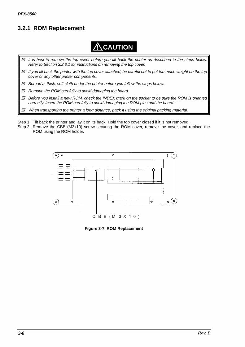
DFX-8500
Rev. B3-8
3.2.1 ROM Replacement
;�It is best to remove the top cover before you tilt back the printer as described in the steps below.Refer to Section 3.2.3.1 for instructions on removing the top cover.
;�If you tilt back the printer with the top cover attached, be careful not to put too much weight on the topcover or any other printer components.
;�Spread a thick, soft cloth under the printer before you follow the steps below.
;�Remove the ROM carefully to avoid damaging the board.
;�Before you install a new ROM, check the INDEX mark on the socket to be sure the ROM is orientedcorrectly. Insert the ROM carefully to avoid damaging the ROM pins and the board.
;�When transporting the printer a long distance, pack it using the original packing material.
Step 1: Tilt back the printer and lay it on its back. Hold the top cover closed if it is not removed.Step 2: Remove the CBB (M3x10) screw securing the ROM cover, remove the cover, and replace the
ROM using the ROM holder.
C B B ( M 3 X 1 0 )
Figure 3-7. ROM Replacement
CAUTION

DISASSEMBLY AND ASSEMBLY
Rev. B 3-9
3.2.2 Printhead and Ribbon Mask Assembly RemovalThe printhead can be changed without disassembling the entire unit.Use the exclusive printhead kit for printhead exchange on the DFX-8500. When you receive the kit, checkthat all of the following are included.
P r i n t h e a d U n i t
O i l ( O - 2 )
H e a d C a b l e P r o t e c t i o n S h e e t
R i b b o n M a s k A s s e m b l y
Figure 3-8. Printhead Kit
The description hereafter is the same as the above instruction Manual, so you may refer to this section orto the Instruction Manual.
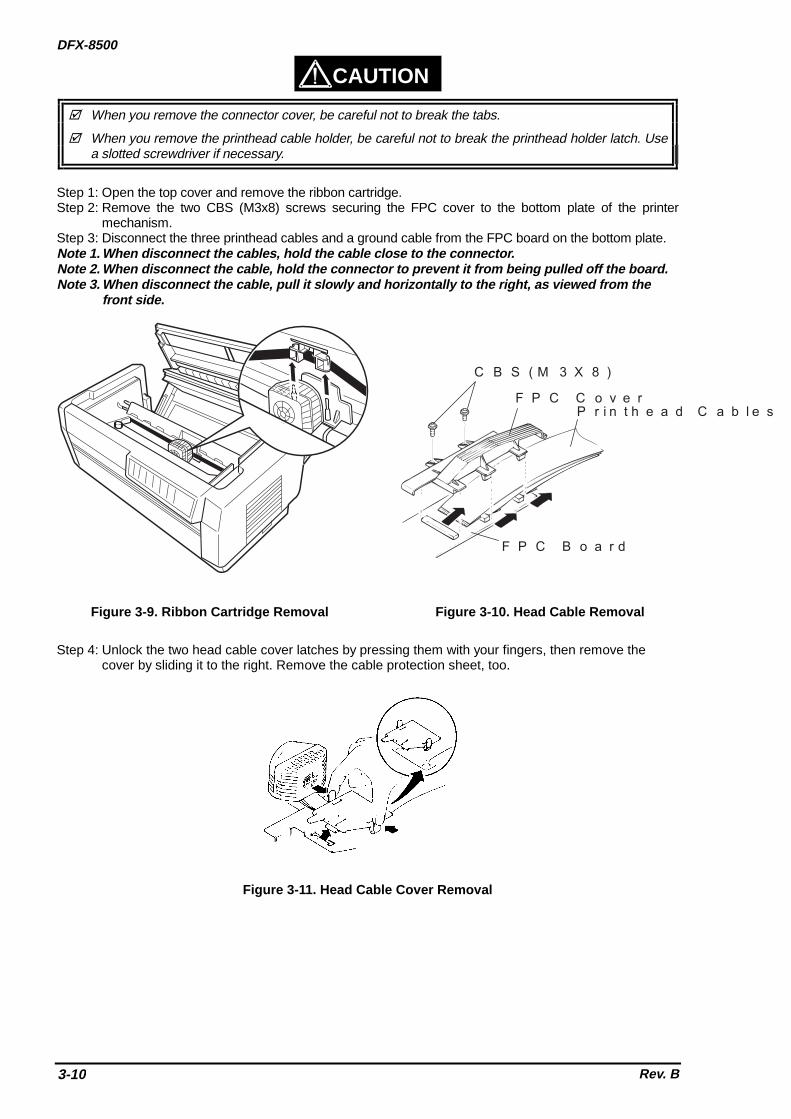
DFX-8500
Rev. B3-10
CAUTION
;�When you remove the connector cover, be careful not to break the tabs.
;�When you remove the printhead cable holder, be careful not to break the printhead holder latch. Usea slotted screwdriver if necessary.
Step 1: Open the top cover and remove the ribbon cartridge.Step 2: Remove the two CBS (M3x8) screws securing the FPC cover to the bottom plate of the printer
mechanism.Step 3: Disconnect the three printhead cables and a ground cable from the FPC board on the bottom plate.Note 1. When disconnect the cables, hold the cable close to the connector.Note 2. When disconnect the cable, hold the connector to prevent it from being pulled off the board.Note 3. When disconnect the cable, pull it slowly and horizontally to the right, as viewed from the
front side.
C B S ( M 3 X 8 )
F P C C o v e rP r i n t h e a d C a b l e s
F P C B o a r d
Figure 3-9. Ribbon Cartridge Removal Figure 3-10. Head Cable Removal
Step 4: Unlock the two head cable cover latches by pressing them with your fingers, then remove thecover by sliding it to the right. Remove the cable protection sheet, too.
Figure 3-11. Head Cable Cover Removal

DISASSEMBLY AND ASSEMBLY
Rev. B 3-11
Step 5: Disconnect the narrow FPC cable from white connector (lock-type). Step 6: Move the carriage to around 90th column, remove the two CP(S-P1)(M4X7) screws securing the
printhead and remove the CP(S-P1)(M3X6) screw securing the ground FPC, then remove theprinthead.
N a r r o w F P C C a b l e
C P ( S - P 1 ) ( M 3 X 6 )
C a r r i a g e
C P ( S - P 1 ) ( M 4 X 7 )
P r i n t h e a d
Figure 3-12. Printhead Removal
Step 7: Disconnect the white connector for the paper width (PW) sensor on the ribbon mask.Step 8: Remove the two shafts securing the ribbon mask to the carriage using a hexagon head screw
wrench, then remove the ribbon mask.
P W S e n s o r C o n n e c t o r
R i b b o nM a s k
S h a f t s
Figure 3-13. Ribbon Mask Removal
Step 9: Install the new printhead, ribbon mask, and cable protection sheet by following Steps1 to 9 in thereverse order.
Step 10: Replace the ribbon mask with a new one. Set the cable of the paper width sensor as shown inFigure 3-13. After installation, check that the ribbon mask is a little loose.
Step 11: Install the new printhead (torque the screws to 12 + 1 kg cm). Replace the head cable protectionsheet with a new one, then connect the head cables to the connector.
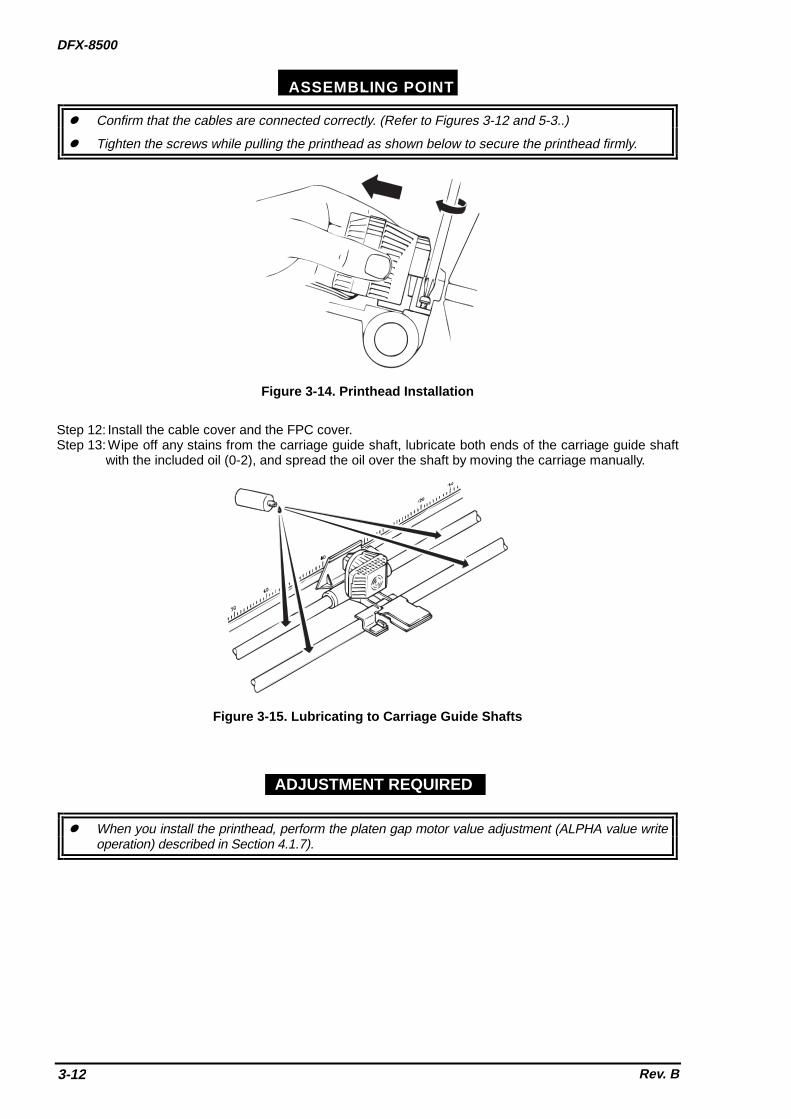
DFX-8500
Rev. B3-12
ASSEMBLING POINT
z� Confirm that the cables are connected correctly. (Refer to Figures 3-12 and 5-3..)
z� Tighten the screws while pulling the printhead as shown below to secure the printhead firmly.
Figure 3-14. Printhead Installation
Step 12: Install the cable cover and the FPC cover.Step 13: Wipe off any stains from the carriage guide shaft, lubricate both ends of the carriage guide shaft
with the included oil (0-2), and spread the oil over the shaft by moving the carriage manually.
Figure 3-15. Lubricating to Carriage Guide Shafts
z� When you install the printhead, perform the platen gap motor value adjustment (ALPHA value writeoperation) described in Section 4.1.7).
ADJUSTMENT REQUIRED

DISASSEMBLY AND ASSEMBLY
Rev. B 3-13
3.2.3 Housing RemovalThis section describes how to remove the housing.
3.2.3.1 Top Cover Removal
CAUTION
;�Two people are required to remove the top cover; one person must hold the top cover while the otherperson removes the screws. If the top cover is not supported while the screws are removed, theweight of the top cover may damage the rear hinges.
Step 1: Open the top cover.Step 2: While someone supports the top cover, remove the four screws (two on the right and two on the
left) securing the top cover to the hinges and remove the cover.
T o p C o v e r
Figure 3-16. Top Cover Removal

DFX-8500
Rev. B3-14
3.2.3.2 Left, Right, and Front Covers Removal and Fuse ReplacementStep 1: Remove the four CBB (M4x16) screws securing the left side cover and remove the cover.Step 2: Remove the right side cover in the same way as you removed the left side cover. Also remove the
four cables from the main switch on the right side cover.
C B B ( M 4 X 1 6 )
C B B ( M 4 X 1 6 ) C B B ( M 4 X 1 6 )
C B B ( M 4 X 1 6 )R i g h t a n d L e f t C o v e r s
Figure 3-17. Left and Right Side Covers Removal
ASSEMBLING POINT
z� When you attach the right side cover, connect the cable from connector CN1 on the C204 powersupply board unit and the cable from the AC inlet to the main switch on the right side cover, asshown below.
M a i n S w i t c h
R e v e r s e s i d e o ft h e s i d e c o v e r ( R )
A C I n l e t S e t
C 2 0 4 P o w e r S u p p l y B o a r d
1 1 1 2
2 4 2 5
CN1
B r o w n c a b l e
B l u e c a b l e
B r o w n c a b l e
B l u e c a b l e
M a g n i f i c a t i o n
Figure 3-18. Cabling for the Main Switch

DISASSEMBLY AND ASSEMBLY
Rev. B 3-15
Step 3: After you remove the right side cover, you can replace the input fuse for the C204 power supplyboard unit.
WARNING
;�Make sure the new fuse meets the printer's AC power specifications.
C a r r i a g e M o t o r
C N 1
C 2 0 4 P S B / P S E B o a r d
G r o u n d i n g H a r n e s s
( R i g h t S i d e )
F u s e
Figure 3-19. Fuse Removal
Step 4: Remove the three CBB (M4x16) screws securing the left side of the front cover to the lower cover.Then remove the front cover along the left hinge.
C B B ( M 4 X 1 6 )
F r o n t C o v e r
Figure 3-20. Front Cover Removal

DFX-8500
Rev. B3-16
3.2.3.3 Front Panel Unit RemovalStep 1: Remove the left and right side covers. (Refer to Section 3.2.3.2)Step 2: Open the top cover and disconnect connector CN5 (the panel unit connector).Step 3: Remove the two CBB (M4x16) screws from the front panel unit and remove the panel unit along
with the panel connector cable.
C B B ( M 4 X 1 6 ) F r o n t P a n e l U n i t
Figure 3-21. Front Panel Removal

DISASSEMBLY AND ASSEMBLY
Rev. B 3-17
3.2.3.4 Upper Case RemovalStep 1: Remove the front panel unit. (Refer to Section 3.2.3.3)Step 2: Remove the six CBB (M4x16) screws, and two CBB (M3x10) screws from the upper case. Then
remove the upper case.
C B B ( M 4 X 1 6 )
C B B ( M 3 X 1 0 )
U p p e r C a s e
Figure 3-22. Upper Case Removal

DFX-8500
Rev. B3-18
3.2.4 Circuit Boards RemovalThis section describes how to remove the circuit boards.
3.2.4.1 Bottom Panel Assembly Removal
CAUTION
;�It is best to remove the top cover before you tilt back the printer as described in the steps below.Refer to Section 3.2.3.1 for instructions on removing the top cover.
;�If you tilt back the printer with the top cover attached, be careful not to put too much weight on the topcover or any other printer components.
;�Spread a thick, soft cloth under the printer before you follow the steps below.
;�When you attach the bottom panel, make sure the parallel interface cable latch is not caughtbetween the lower case and bottom panel.
Step 1: Remove the left and right side covers. (Refer to Section 3.2.3.2)Step 2: On the right side of the printer mechanism, remove the CBS (O) screw securing the green and
yellow earth cable and the earth plate together.
E a r t h C a b l e
C B S ( O ) S c r e w ( M 4 x 8 )
C 2 0 4 P S B / P S EB o a r d
( R i g h t s i d e )
B o t t o m P a n e lA s s e m b l y
Figure 3-23. Connector and Earth Cable Removal (right side)

DISASSEMBLY AND ASSEMBLY
Rev. B 3-19
Step 3: From the left side, remove the two CPB(O)(M4X8) screws securing the green and yellow earth
cables between the bottom plate of the printer mechanism and the earth on the bottom panelassembly.
Step 4: Disconnect the 6 connectors, (1) through (6) as shown in Figure 3-24.
E a r t h C a b l e
E a r t h C a b l e
32 6
1
5
4
F l a t C a b l e C o n n e c t o r ( 5 0 - p i n ) : M e c h a n i s mC N 4 ( 4 - p i n ) : C R C o n n e c t o r
C N 9 ( 7 - p i n ) : O p t i o n C u t t e r
F l a t C a b l e C o n n e c t o r ( 5 0 - p i n ) : P r i n t h e a dC N 3 ( 2 - p i n ) : C o v e r O p e n S e n s o r
C N 5 ( 1 4 - p i n ) : P a n e l U n i t
123
654
Figure 3-24. Connector and Earth Cable Removal (left side)
Step 5: Open the rear cover. Remove the four CBB (M3x12) screws and two CB(M3x12) screws securing
the interface cover and remove the cover.Step 6: Remove the 2 CB(M3x12) screws securing the optional interface cover and remove the cover.
C B ( M 3 X 1 2 )
C B B ( M 3 X 1 2 )
R e a r C o v e r
O p t i o n a l I n t e r f a c e C o v e r
I n t e r f a c e C o v e r
Figure 3-25. Interface Cover Removal

DFX-8500
Rev. B3-20
Step 7: While supporting the top cover to protect it from scratches, tilt back the printer and lay it on its back.Step 8: Remove the eight CBB (M4x16) screws securing the bottom panel assembly, and slowly remove the
bottom panel unit assembly.
C B B ( M 4 X 1 6 )
Figure 3-26. Bottom Panel Assembly Removal

DISASSEMBLY AND ASSEMBLY
Rev. B 3-21
3.2.4.2 Cooling Fan and C204 Power Supply Board Unit RemovalStep 1: Remove the bottom panel assembly. (Refer to Section 3.2.4.1)Step 2: If you need to remove the cooling fan, disconnect connector CN5 and remove the four CCN (M3x30)
screws securing it, and remove the fan.Step 3: Disconnect connectors CN2, CN3, and CN4.Step 4: Remove the six CBB (M3x12) screws and CPN (O) (M3x8) screw securing the C204 power supply
board unit and remove the board.
C B B ( M 3 X 1 2 )
C N 3
C N 5
C 2 0 4 P S B / P S E B o a r d
C N 4
C 2 0 4 M A I N B o a r d
C N 1
A C I n l e t S e tC C N ( M 3 X 3 0 ) C P N ( O ) ( M 3 X 8 )
C N 2
Figure 3-27. C204 PSE/PSB Board Removal

DFX-8500
Rev. B3-22
3.2.4.3 C204 SUB Board Unit RemovalStep 1: Remove the bottom panel assembly. (Refer to Section 3.2.4.1)Step 2: Disconnect connectors CN15 and CN16 on the C204 MAIN board.Step 3: Remove the CBB (M3x8) screw and the CBB (M3x12) screw securing the C204 SUB board
assembly and remove the board.
C B B ( M 3 X 1 2 )
C B B ( M 3 X 8 )
C N 1 6
C N 1 5
C N 1 5
C N 1 6
C 2 0 4 M A I N B o a r d
C 2 0 4 S U B B o a r d U n i t
Figure 3-28. C204 SUB Board Unit Removal

DISASSEMBLY AND ASSEMBLY
Rev. B 3-23
3.2.4.4 C204 DRV-B and C204 DRV Board Units RemovalStep 1: Remove the bottom panel assembly. (Refer to Section 3.2.4.1)Step 2: Disconnect connector CN3 and cable connector CN14 for the C204 DRV board.Step 3: Disconnect connectors CN1 and CN2 on the C204 DRV-B board.
C 2 0 4 D R V B o a r d
C N 3
C N 1 4
C 2 0 4 D R V - B B o a r d
C N 2
C N 1
C a b l e ( f r o m C 2 0 4 M A I N b o a r d )C 2 0 4 M A I N b o a r d
Figure 3-29. C204 DRV/DRV-B Boards Removal ½
Step 4: Remove the eight CBS (M3x8) screws securing the C204 DRV-B board and C204 DRV board viashielding plate respectively.
S h i e l d i n g P l a t e
S h i e l d i n g P l a t e
C 2 0 4 D R V B o a r d
C 2 0 4 D R V - B B o a r d
: C B S ( M 3 X 8 ) X 8
Figure 3-30. C204 DRV/DRV-B Boards Removal 2/2

DFX-8500
Rev. B3-24
3.2.4.5 C204 MAIN Board Unit Removal Step 1: Remove the bottom panel assembly. (Refer to Section 3.2.4.1) Step 2: Remove the C204 SUB board unit (Refer to Section 3.2.4.3.) Step 3: Remove the C204 DRV-B board and C204 DRV board units (Refer to Section 3.2.4.4.) Step 4: Disconnect connectors CN6, CN7, CN8, and CN10.
H a r n e s s
C N 3
t o C N 6 ( 7 - p i n )
t o C N 7 ( 6 - p i n )
C N 2
C 2 0 4 M A I N B o a r d
Figure 3-31. C204 MAIN Board Removal 1/4
C N 4
H a r n e s s
C N 1 0( 8 - p i n )
C 2 0 4 M A I N B o a r d
t o C N 1 0( 8 - p i n )
t o C N 4
Figure 3-32. C204 MAIN Board Removal 2/4
H a r n e s s
C N 8 ( 8 - p i n )
C 2 0 4 M A I N B o a r d
Figure 3-33. C204 MAIN Board Removal 3/4

DISASSEMBLY AND ASSEMBLY
Rev. B 3-25
Step 5: Remove the four CBB (M3x12) screws and two CBS (O) (M3x8) screws securing the C204 MAINboard unit and remove the board.
: C B B ( M 3 X 1 2 ) X 4
: C B S ( O ) ( M 3 X 8 ) X 2
C 2 0 4 M A I N B o a r d U n i t
H o o k s f o r C 2 0 4 M A I N B o a r d I n s t a l l a t i o n
Figure 3-34 . C204 MAIN Board Removal 4/4
When you install the C204 MAIN board assembly, perform the following adjustments:
z� Platen gap motor value (platen gap) adjustment (described in Section 4.1.7).
z� Bidirectional printing adjustment (described in Section 4.1.8).
ADJUSTMENT REQUIRED

DFX-8500
Rev. B3-26
3.2.4.6 AC Inlet RemovalStep 1: Remove the C204 power supply board assembly. (Refer to Section 3.2.4.2)Step 2: Remove the C204 MAIN board assembly. (Refer to Section 3.2.4.5)Step 3: Remove the three CBB (M3x8) screws and one CB (O) (M4x6) screw securing the grounding
plate to the bottom panel assembly and remove the grounding plate.
C B B ( M 3 X 8 ) B o t t o m P a n e l A s s e m b l yG r o u n d i n g P l a t e
C B ( O )( M 4 X 6 )
A C I n l e t S e t
Figure 3-35. Grounding Plate Removal
Step 4: Remove the two CFS (M3x10) screws securing the AC inlet to the grounding plate and removethe AC inlet.
A C I n l e t S e t
G r o u n d i n g P l a t e
C F S ( M 3 X 1 0 )
Figure 3-36. AC Inlet Removal
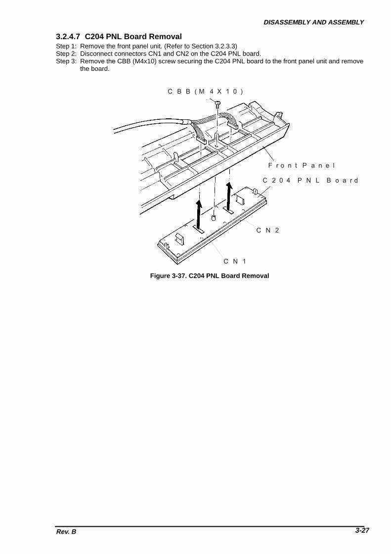
DISASSEMBLY AND ASSEMBLY
Rev. B 3-27
3.2.4.7 C204 PNL Board RemovalStep 1: Remove the front panel unit. (Refer to Section 3.2.3.3)Step 2: Disconnect connectors CN1 and CN2 on the C204 PNL board.Step 3: Remove the CBB (M4x10) screw securing the C204 PNL board to the front panel unit and remove
the board.
C B B ( M 4 X 1 0 )
F r o n t P a n e l
C 2 0 4 P N L B o a r d
C N 2
C N 1
Figure 3-37. C204 PNL Board Removal

DFX-8500
Rev. B3-28
3.2.5 Interlock Switch and Cover Open Sensor Assembly RemovalStep 1: Remove the upper case. (Refer to Section 3.2.3.4)Step 2: Disconnect the interlock switch cable and the cover open sensor cable from the junction board
respectively.
C o v e r O p e n S e n s o r
I n t e r l o c k S W .
C N 3
C o n n e c t o rJ u n c t i o n B o a r d
C 2 0 4 M A I N B o a r d
W h i t e : 2 - p i n
R e d : 3 - p i n
C o v e r O p e n S e n s o r C o n n e c t o r
Figure 3-38. Interlock Switch Assembly Removal
Step 3: Remove the CBB (M4x10) screw securing the interlock switch assembly to the lower case. andremove it.
Step 4: Remove the CBB (M3x10) screw securing the cover open sensor to the upper case. and removeit.
I n t e r l o c k S W A s s e m b l y
C B B ( M 4 X 1 0 )
L o w e r C a s e
Figure 3-39. Interlock Switch Assembly Removal
U p p e r C a s e
C B B ( M 3 X 1 0 )
C o v e r O p e n S e n s o r
Figure 3-40. Interlock Switch and Cover Open Sensor Removal

DISASSEMBLY AND ASSEMBLY
Rev. B 3-29
3.2.6 Printer Mechanism RemovalThis section describes how to remove and disassemble the printer mechanism. Before following the steps inthis section, remove the printer mechanism from the printer as described in Section 3.2.6.
Because the printer mechanism is large and heavy, you must be careful when you remove it. Whenyou lift or lower the printer mechanism, follow these precautions:
;�Two people are required to remove or install the printer mechanism.
;�Use the lift handles (#E656, part number B765111001) designed for lifting or lowering the printermechanism when you remove or install it.
;�To avoid straining your waist, hands, or feet, place the printer on a low table before following thesteps below.
Step 1: Remove the upper case. (Refer to Section 3.2.3.4.)Step 2: Remove the interlock switch assembly. (Refer to Section 3.2.5)Step 3: Remove the two CBS (O) (M4x8) screws securing the green and yellow earth cables to the
grounding plate. Then disconnect connectors (1) through (4) as shown in Figure 3-41. (Ensure allconnectors (1) through (7) indicated in the figure are disconnected.)
Step 4: Remove the CBS (O) (M4x8) screw securing the earth cable as shown in Figure 3-42.
E a r t h C a b l e E a r t h C a b l e3726
1
5
4
3
7
2
654
1 F l a t C a b l e C o n n e c t o r ( 5 0 - p i n ) : M e c h a n i s mC N 4 ( 4 - p i n ) : C R C o n n e c t o rC N 9 ( 7 - p i n ) : O p t i o n C u t t e rF l a t C a b l e C o n n e c t o r ( 5 0 - p i n ) : P r i n t h e a dI n t e r l o c k S w i t c h C a b l e ( 2 - p i n )C N 3 ( 2 - p i n ) : C o v e r O p e n S e n s o rC N 5 ( 1 4 - p i n ) : P a n e l U n i t
Figure 3-41. Connector Removal (left side)
E a r t h C a b l e
C B S ( O ) S c r e w ( M 4 x 8 )
C 2 0 4 P S B / P S EB o a r d
( R i g h t s i d e )
B o t t o m P a n e lA s s e m b l y
Figure 3-42. Connector Removal (right side)
WARNING

DFX-8500
Rev. B3-30
Step 5: Remove the four screws securing the printer mechanism to the lower case.
S c r e w sS c r e w s
Figure 3-43. Printer Mechanism Removal 1/2
Step 6: Install the lift handles from the inside of the printer mechanism. Insert each handle through the
two holes in the side frames of the printer mechanism. Then slowly lift up the printer mechanismusing the handles and remove it from the lower case.
L i f t H a n d l e # E 6 5 6
P r i n t e r M e c h a n i s m
L o w e r H o u s i n g A s s e m b l y
Figure 3-44. Printer Mechanism Removal 2/2
ASSEMBLING POINT
When you install the printer mechanism, route the cables as shown in Figures 3-41 and 3-42. Make surethe cables do not get caught between the printer mechanism and lower case.
ADJUSTMENT REQUIRED
When you install the printer mechanism, perform the following adjustments:
� Platen gap motor value (platen gap) adjustment (described in Section 4.1.7)
� Bidirectional printing adjustment (described in Section 4.1.8)

DISASSEMBLY AND ASSEMBLY
Rev. B 3-31
3.2.6.1 Fan RemovalStep 1: Remove the upper case unit. (Refer to Section 3.2.3.4.)Step 2: Remove the right cover. (Refer to Section 3.2.3.2.)Step 3: Disconnect the connector for the fan from the relay connector.Step 4: Remove the CP(O) screw securing the fan duct to the left frame and the CC screw securing the
fan and the fan duct to the shaft on the left frame. Then remove the fan along with the fan duct.
C P ( O ) ( 4 x 5 )
C C ( 3 x 3 0 )
L e f t F r a m e
Figure 3-45. Fan Removal

DFX-8500
Rev. B3-32
3.2.6.2 Ribbon Feed Change Lever Unit Removal
Step 1: Release the three hooks securing the ribbon feed gear cover to the ribbon feed motor frame andremove the cover and the ribbon feed gear.
Step 2: Disconnect the three connectors for the ribbon feed motor, tractor select sensor, and the ribbonjam sensor from the connector junction board, as shown in Figure 3-47 and Figure 3-48.
Step 3: Remove the head damper from the left side frame.Step 4: Remove the fan on the left frame. (Refer to Section 3.2.6.1.)
H e a d D u m p e r( L e f t )
R i b b o n F e e d G e a r C o v e r
R i b b o n F e e d G e a r
R i b b o n F e e d M o t o r
R i b b o n F e e d M o t o r F r a m e
R i b b o n F e e dC h a n g e L e v e r U n i t
Figure 3-46. Ribbon Feed Change Lever Unit Removal (1/2)
Step 5: Remove the two CBS (M3x6) screw securing the ribbon feed change lever unit to the left side frame,
then remove the ribbon feed change lever unit.
C o n n e c t o r J u n c t i o n B o a r d
R i b b o n F e e d C h a n g e L e v e r U n i t
C o n n e c t o r f o rR i b b o n F e e d m o t o r ( W )
C o n n e c t o r f o rT r a c t o r S e l e c t S e n s o r ( Y )
C B S ( M 3 X 6 )
C B S ( M 3 X 6 )
C o n n e c t o r f o rR i b b o n J a m S e n s o r ( R )
Figure 3-47. Ribbon Feed Change Lever Unit Removal (2/2)

DISASSEMBLY AND ASSEMBLY
Rev. B 3-33
T o R i b b o n J a m S e n s o r
T o T r a c t o r S e l e c t S e n s o rT o R F M o t o r
C o n n e c t o r J u n c t i o n B o a r d
Figure 3-48. Removing Connectors
ASSEMBLING POINT
When you install the ribbon feed change lever unit, join the tip of the tractor select lever and the tractorselect gear holder correctly. (Refer to Figure 2-12.)

DFX-8500
Rev. B3-34
3.2.6.3 Tractor Select Lever (Upper and Lower) Assembly DisassemblyThis section describes how to disassemble the tractor select lever assembly, including how to remove theribbon feed motor and tractor select sensor.
Step 1: Remove the ribbon feed change lever unit. (Refer to Section 3.2.6.2.)Step 2: Remove the two CP(S-P1)(M3x6) screws, leaf springs, and washers securing the ribbon feed
motor to the ribbon feed motor frame and remove the motor.Step 3: Remove the E ring (# 3) securing the upper/lower tractor select levers and remove the levers.Step 4: Remove the E ring (# 3) securing the tractor select cam and remove the cam.Step 5: Remove the CPS(P1)(M2x10) screw securing the tractor select sensor and remove the sensor.Step 6: Using wire cutters, cut the wire band securing the ribbon feed motor and tractor select sensor
cables to the ribbon feed motor frame.
E - r i n g ( 3 )
W a s h e rL e a f S p r i n g
T r a c t o r S e l e c t T r a n s m i s s i o n G e a r
E - r i n g ( 3 )
T r a c t o r S e l e c tT r a n s m i s s i o n G e a r
R i b b o n F e e d M o t o rF r a m e
R i b b o n F e e d M o t o r
C P ( S - P 1 ) ( M 3 X 6 )
T r a c t o r S e l e c tL e v e r l o w e r
T r a c t o r S e l e c tS e n s o r
T r a c t o r S e l e c tL e v e r S p r i n g
T r a c t o r S e l e c t L e v e r U p p e r
T r a c t o r S e l e c t C a m
C P S ( P 1 ) ( M 2 X 1 0 )
Figure 3-49. Tractor Select Lever Disassembly
ASSEMBLING POINT
z� Attach the tractor select levers to the tractor select cam as shown in Figure 3-50.
R i b b o n F e e d M o t o r F r a m e
T r a c t o r S e l e c t C a m
T a r c t o r S e l e c t G e a r H o l d e r
R i b b o n F e e d C h a n g e L e v e r( U p p e r a n d L o w e r )
Figure 3-50. Tractor Select Lever Installation

DISASSEMBLY AND ASSEMBLY
Rev. B 3-35
3.2.6.4 Ribbon Jam Sensor RemovalStep 1: Remove the right cover. (Refer to Section 3.2.3.2)Step 2: Disconnect the connector for the sensor from the connector junction board.Step 3: Remove the CP(S-P1) (M3x6) screw securing the sensor to the bracket, and remove the sensor.
C P ( S - P 1 ) ( M 3 x 6 )
F r o n t / R e a r T r a c t o r S e l e c t L e v e r A s s e m b l y
Figure 3-51. Ribbon Jam Sensor Removal

DFX-8500
Rev. B3-36
3.2.6.5 Connector Junction Board Assembly and FPC Board Assembly Removal
This section describes how to remove the connector junction board assembly and FPC board assembly.
Step 1: Remove the left side cover. (Refer to Section 3.2.3.2)Step 2: Disconnect all the cables from the connector junction board assembly. Remove the two CP (S-
P1) (M3x6) screws securing the connector junction board assembly to the printer mechanism andthen remove the connector junction board assembly.
Step 3: Remove the front/rear tractor select lever assembly. (Refer to Section 3.2.6.2)Step 4: Disconnect the connector for the CR sensor (encoder) from the FPC board assembly.Step 5: Remove the 2 CBS (M3x8) screws securing the FPC cover and remove the cover (Refer to
Figure 3-10). Then remove the CPS(P-1) (M3x6) screw securing the FPC board assembly to theprinter mechanism and remove the FPC board assembly.
C o n n e c t o r J u n c t i o n B o a r d
F P C B o a r d A s s e m b l y
C R E n c o d e r C o n n e c t o r
C P S ( S P - 1 ) ( M 3 x 6 )
C P S ( P 1 ) ( M 3 x 6 )
Figure 3-52. Connector Junction Board Removal
ASSEMBLING POINT
When you connect the cables to the connector junction board assembly, note that the matchingconnectors have the same color and number of pins (Refer to APPENDIX Figure A-15.).

DISASSEMBLY AND ASSEMBLY
Rev. B 3-37
3.2.6.6 PG Sensor and PG Motor Removal
CAUTION
When you remove or install the PG sensor, be careful not to bend the PG motor encoder plate.
Step 1: Remove the connector junction board assembly. (Refer to Section 3.2.6.5)Step 2: Remove the CBS screw (3X6) securing the PG sensor unit to the left frame. Then take out the
unit to the front and remove it.Step 3: Remove the screw securing the PG sensor to the unit, and remove the sensor.Step 4: Remove two CP (S-P1) (M3x6) screws securing the PG motor and remove the motor.
E n c o d e r P l a t e
P G M o t o r P i n i o n G e a r
P l a t e n G a p S e n s o r
C P S ( P ) ( M 3 X 6 )
P G M o t o r
C P ( S - P 1 ) ( M 3 x 6 )
Figure 3-53. PG Sensor and PG Motor Removal
ASSEMBLING POINT
• When you install the PG motor, make sure the backlash between the PG motor and PG motortransmission gear is between 0.05 and 0.15 mm (almost no backlash).
• When you install the PG sensor unit, align the C-cut portion of the unit with the lower shaft securingthe PG motor to the frame.
When you install the PG sensor or PG motor, perform the platen gap motor value (platen gap)adjustment, as described in Section 4.1.7.
ADJUSTMENT REQUIRED

DFX-8500
Rev. B3-38
3.2.6.7 Plunger and Paper Bail Assembly Removal
This section describes how to remove the plunger (loading solenoid) and paper bail assembly.
Step 1: Disconnect the black, 2-pin plunger connector from the connector junction board assembly, andremove the plunger cable from the connector junction board assembly.
Step 2: Remove the two CP(S-P1) (M3x6) screws securing the plunger to the left side frame and removethe plunger.
Step 3: Remove the iron core of the plunger from the paper bail shaft.
P l u n g e r
I r o n C o r e C P ( S - P 1 ) ( M 3 X 6 )
2 - p i nB l a c k
Figure 3-54. Plunger Removal

DISASSEMBLY AND ASSEMBLY
Rev. B 3-39
Step 4: Remove the left tension roller lever spring.Step 5: Remove the E-ring (6) securing the paper bail shaft to the left frame and remove the platen roller
shaft holder and paper bail lever.
E - r i n g s
S h a f t H o l d e rP a p e r B a i l S h a f t
P a p e r B a i l L e v e r
E - r i n g
T e n s i o n R o l l e r L e v e r S p r i n g
Figure 3-55. Paper Bail Assembly Removal 1/2
Step 6: Disconnect 2 fan harnesses and remove 2 screws (CPS-P1) securing the CR fan duct. Thenremove the CR fan duct along with the CR fan. (Refer to Section 3.2.6.1.)
Step 7: Remove the right tension roller lever spring.Step 8: Remove 2 E-rings to release the release tension lever at the inner side of the left frame.Step 9: Remove the E-ring (6) at the right end of the paper bail shaft. Then remove the paper bail lever,
leaf spring and shaft holder.Step 10: Slide the shaft left to release the right end of the shaft from the right frame. Then lift up the shaft
by the right end and remove it along with the release tension lever.
E - r i n g ( 6 )
P a p e r B a i l A s s e m b l y
P a p e r B a i l L e v e r
L e a f S p r i n g
S h a f t H o l d e r
Figure 3-56. Paper Bail Assembly Removal 2/2

DFX-8500
Rev. B3-40
3.2.6.8 Upper Paper Guide and Top PE Sensor Removal
Step 1: Remove the paper bail assembly. (Refer to Section 3.2.6.7)Step 2: Disconnect the red, 3-pin, top PE sensor connector from the connector junction board assembly.
C o n n e c t o r J u n c t i o n B o a r d
T o p P E S e n s o rC o n n e c t o r
L e f t S i d e F r a m e
Figure 3-57. Top PE Sensor Connector Removal
Step 3: Remove the two CBS (M4x6) screws securing the upper paper guide to both frames and remove the
paper guide.Step 4: Remove the two CPS(SP) (M3x8) screws securing the top PE sensor to the upper paper guide and
remove the sensor.
T o p P E S e n s o r U p p e r P a p e r G u i d e
C B S ( M 4 X 6 ) C P S ( S P ) ( M 4 X 8 ) C B S ( M 4 X 6 )
Figure 3-58. Top PE Sensor Removal

DISASSEMBLY AND ASSEMBLY
Rev. B 3-41
3.2.6.9 Tension Roller Shaft Removal
This section describes how to remove the tension roller shaft. It is better to remove the tension roller shaftwith the paper bail assembly removed; however, removing it is not required. (Refer to Section 3.2.6.7.) forinstructions on how to remove the paper bail assembly.)
Step 1: Remove the connector junction board assembly. (Refer to Section 3.2.6.5.)Step 2: Remove the paper bail assembly. (Refer to Section 3.2.6.7.)Step 3: While pushing the tension pulley to the front, remove the CR timing belt.Step 4: Remove the upper paper guide. (Refer to Section 3.2.6.8.)Step 5: Using tweezers, unlock the locking tab of the tension roller gear at the left end of the tension roller
shaft, and remove the gear.Step 6: Remove the E-ring (6) on the left end of the tension roller shaft and remove the shaft holder.
E - r i n g ( 6 )
T e n s i o n R o l l e r G e a r
T e n s i o n R o l l e r S h a f t H o l d e r
T e n s i o n R o l l e r S h a f tA s s e m b l y
L e f t
R i g h t
Figure 3-59. Tension Roller Gear Removal

DFX-8500
Rev. B3-42
Step 7: Remove the CR motor fan. (Refer to Section 3.2.6.19.)Step 8: Remove the E-ring (6) at the right end of the tension roller shaft and remove the tension roller shaft
holder along with the leaf spring and the washer.Step 9: Remove the tension roller shaft by taking it out from the right frame.
T e n s i o n R o l l e r S h a f t A s s e m b l y T e n s i o n R o l l e r S h a f t H o l d e r
L e a f S p r i n g
E - r i n g
C a r r i a g e M o t o r
W a s h e r
Figure 3-60. Shaft Holder Removal
T e n s i o n R o l l e r S h a f tA s s e m b l y
F r o n t
L e f t
Figure 3-61. Tension Roller Shaft Removal

DISASSEMBLY AND ASSEMBLY
Rev. B 3-43
3.2.6.10 Platen Removal
Step 1: Remove the paper bail assembly. (Refer to Section 3.2.6.7.)Step 2: Remove the upper paper guide. (Refer to Section 3.2.6.8.)Step 3: Remove the four hexagon socket screws securing the platen to the platen holders. Then remove
the platen with the lower paper guide composed of 3 parts in it.Step 4: Slide the 3 parts of the lower paper guide to release the notches and remove them one by one
from the platen.
H e x a g o n S o c k e t S c r e w
P l a t e n
P l a t e n H o l d e r ( L e f t ) P l a t e n H o l d e r ( R i g h t )L o w e r P a p e r G u i d e
R e a r
Figure 3-62. Platen Removal
P l a t e n
P l a t e n H o l d e r P o s i t i o n n i n g T a b
0 . 0 3 m mT h i c k n e s s G a u g e
F r o n t
R e a r
N o t h r o u g h
Figure 3-63. Platen Positioning
ASSEMBLING POINT
• When you attach the 3 parts of the lower paper guide to the platen, start with the one at the right endand work toward the left.
• When you mount the platen to the platen holders, space between the platen and positioning tab onthe both sides must be less than 0.03mm. (Refer to Figure 3-63.)
ADJUSTMENT REQUIRED
When you install the platen, perform the following adjustments:
• Carriage guide shaft parallelism adjustment (described in Section 4.1.5 and Section 4.1.6)
• Platen angle (right angle) adjustment (described in Section 4.1.6)
• Platen gap motor value (platen gap) adjustment (described in Section 4.1.7)

DFX-8500
Rev. B3-44
3.2.6.11 Paper Jam Sensor Removal
Step 1: Remove the platen along with the lower paper guide composed of 3 parts. (Refer to Section3.2.6.10.)
Step 2: Remove the CPN(SP)(M4x8) screw securing the left part of the lower paper guide to the platen.Step 3: Remove the part from the platen.
L o w e r P a p e r G u i d e
C P N ( S P ) ( M 4 X 8 )
P l a t e n
R i g h t
L e f t
Figure 3-64. Lower Paper Guide Left Part Removal
Step 4: Unhook the paper jam sensor (magnetic transistor) cover to remove it.Step 5: Remove the paper jam sensor.
P a p e r J a m S e n s o r
P a p e r J a m S e n s o r C o v e r
L o w e r P a p e r G u i d e ( L e f t )
Figure 3-65. Paper Jam Sensor Removal
ASSEMBLING POINT
When you attach the paper jam sensor, make sure it is oriented correctly (front to back).

DISASSEMBLY AND ASSEMBLY
Rev. B 3-45
3.2.6.12 Pull Tractor Sensor Removal
Step 1: Remove the upper paper guide. (Refer to Section 3.2.6.8)Step 2: Disconnect the red 2-pin pull tractor sensor connector from the connector junction board
assembly.Step 3: Remove the CP(S) (M2x14) screw securing the pull tractor sensor (a micro-switch type sensor) to
the left side frame and remove the sensor.
C P ( S ) ( M 2 X 1 4 )
W a s h e r
P u l l T r a c t o r S e n s o r
P l a t e n H o l d e r ( R i g h t )
H e x a g o n N u t
Figure 3-66. Pull Tractor Sensor removal

DFX-8500
Rev. B3-46
3.2.6.13 Paper Width (PW) Sensor Removal
Step 1: Disconnect the connector for the PW sensor.Step 2: Remove the CP(S-P1) (M2.5x6) screw securing the PW sensor to the ribbon mask holder.
C P ( S - P 1 ) ( M 2 . 5 x 6 )
P a p e r W i d t h S e n s o r
P a p e r W i d t h S e n s o r C o n n e c t o r
Figure 3-67. PW Sensor Removal

DISASSEMBLY AND ASSEMBLY
Rev. B 3-47
3.2.6.14 PG Home Sensor Removal
Step 1: Remove the front/rear tractor select lever assembly. (Refer to Section 3.2.6.2.)Step 2: Remove the E-ring securing the carriage guide shaft gear to the rear carriage guide shaft.
C a r r i a g e G u i d e S h a f t( R e a r )
E - r i n g
C a r r i a g e G u i d e S h a f tG e a r
Figure 3-68. Carriage Guide Shaft Gear Removal
Step 3: Disconnect the white, 2-pin, PG home sensor connector from the connector junction board
assembly.Step 4: Detach the hook securing the PG home sensor and remove the sensor.
P G H o m e S e n s o r
P l a t e n G a p ( P G ) M o t o r
Figure 3-69. PG Home Sensor Removal

DFX-8500
Rev. B3-48
ASSEMBLING POINT
When you install the CR guide shaft gear, align the rib in the CR guide shaft gear with the PG adjustmenttransmission gear as shown in the figure below, then rotate the CR guide shaft gear 10 mm in CCW.
F r a m e L e f t
C R G u i d e S h a f t G e a r
P G T r a n s m i s s i o n G e a r
F l a t P a r t o f C R G u i d e S h a f t ( R e a r )
A d v a n c e 1 0 m m
S t o p p e r
Figure 3-70. CR Guide Shaft Gear Phase Alignment

DISASSEMBLY AND ASSEMBLY
Rev. B 3-49
3.2.6.15 PF Motor Removal
Step 1: Remove the connector junction board assembly. (Refer to Section 3.2.6.5.)Step 2: Remove the three CP (SP-1) (M4x8) screws securing the PF motor to the left side frame.Step 3: Remove the PF motor from the inside of the left side frame.
C P ( S - P 1 ) ( M 4 X 8 )
P a p e r F e e d M o t o r
Figure 3-71. PG Home Sensor Removal

DFX-8500
Rev. B3-50
3.2.6.16 Left Side Frame Gear Removal
Step 1: Remove the front/rear tractor select lever assembly. (Refer to Section 3.2.6.2.)Step 2: Remove the connector junction board assembly. (Refer to Section 3.2.6.5.)Step 3: Remove the PG motor. (Refer to Section 3.2.6.6.)Step 4: Remove the series of gears in the order indicated by the numbers in Figure 3-72.
Figure 3-72. Left Side Frame Gear Removal

DISASSEMBLY AND ASSEMBLY
Rev. B 3-51
3.2.6.17 Front Tractor Assembly Removal
This section describes how to remove the front tractor assembly.
Step 1: Disconnect the connector white 3-pin front PE sensor from the connector junction board.Step 2: Remove the connector junction board assembly. (Refer to Section 3.2.6.5.)Step 3: Lay the mechanism on its back.Step 4: Remove the screw securing the tractor wire holder to the left side frame and remove the holder.Step 5: Loosen the flange nut securing the front tractor assembly to the left side frame by the left end,
and remove the tractor transmission gear.Step 6: Remove the flange nut on the right side and remove the right tractor wire spring holder set.Step 7: Remove the E-ring (6) securing the rear shaft of the front tractor assembly to the left side frame
and remove the shaft holder.Step 8: Move the assembly to left to release the right end of the shaft, then release the left side of the shaft
from the left side frame and remove the assembly.
C B S ( M 4 X 8 )
T r a c t o r W i r e H o l d e r ( L )
C a r r i a g eM o t o r
F l a n g e N u t
T r a c t o rW i r e S p r i n g
T r a c t o r W i r e H o l d e r ( R )
< L e f t > < R i g h t >Figure 3-73. Tractor Wire Removal
S h a f t H o l d e rE - r i n g ( 6 ) T r a c t o r A s s e m b l y ( F r o n t )
S h a f t H o l d e rL e a f S p r i n g
W a s h e r
E - r i n g ( 6 )
T r a c t o r T r a n s m i s s i o n G e a r
F l a n g e N u t
F l a n g e N u t
Figure 3-74. Front Tractor Assembly Removal
ADJUSTMENT REQUIRED
• When you install the front tractor assembly, perform the tractor wire spring adjustment, as describedin Section 4.1.3.

DFX-8500
Rev. B3-52
3.2.6.18 Rear Tractor Assembly Removal
This section describes how to remove the rear tractor assembly.
Step 1: Disconnect the connector white 3-pin rear PE sensor from the connector junction board.Step 2: Remove the connector junction board assembly. (Refer to Section 3.2.6.5.)Step 3: Remove the flange nut securing the wire holder spring set to the right side frame, and remove the
set.Step 4: Loosen the flange nut securing the rear tractor assembly to the left side frame.Step 5: Remove the CBS(M4x8) screw securing the tractor wire holder and remove the holder.Step 6: Remove the rear tractor gear.Step 7: Remove the E-ring and release the shaft holder from the left side frame.Step 8: To remove the rear tractor assembly, first move it to the left to release the right end of the shaft
from the right side frame. Then release the left end of the shaft and remove the assembly.
S h a f t H o l d e r
E - r i n g ( 6 )
T r a c t o r A s s e m b l y ( R e a r )
W a s h e rL e a f S p r i n g
F l a n g e N u t
S h a f t H o l d e r
E - r i n g ( 6 )
F l a n g e N u t
L e f tR i g h t
T r a c t o r W i r e H o l d e r
C P N ( M 4 x 8 )
T r a c t o r G e a r
Figure 3-75. Rear Tractor Assembly Removal
When you install the rear tractor assembly, perform the tractor wire spring adjustment, as described inSection 4.1.3.
ADJUSTMENT REQUIRED

DISASSEMBLY AND ASSEMBLY
Rev. B 3-53
3.2.6.19 CR Motor Fan Removal
Step 1: Disconnect the cable for the motor from the relay connector.Step 2: Remove 2 fan fixing screws and remove the fan.
F a n F i x i n g S c r e w s
R i g h t F r a m e
C R M o t o r F a n
Figure 3-76. CR Motor Fan Removal

DFX-8500
Rev. B3-54
3.2.6.20 CR Motor Removal
Step 1: Remove the right cover. (Refer to Section 3.2.3.2.)Step 2: Disconnect the red and black cables from the terminals on the CR motor. (two cables for each
terminal)Step 3: Remove the three CP(S) (M4x10) screws securing the CR motor to the right side frame and remove
the motor.
C P ( S ) ( M 4 X 1 0 )
C R M o t o r
Figure 3-77. CR Motor Removal
ADJUSTMENT REQUIRED
• When you install the CR motor, perform the carriage timing belt tension adjustment, as described inSection 4.1.2.
• When you install the printhead, perform the platen gap motor value (platen gap) adjustment, asdescribed in Section 4.1.7.

DISASSEMBLY AND ASSEMBLY
Rev. B 3-55
3.2.6.21 CR (Carriage Encoder) Sensor Removal
Step 1: Remove the printhead. (Refer to Section 3.2.2.)Step 2: Disconnect the red 4-pin CR sensor connector from the carriage connector junction board.Step 3: Remove the two CP(S-P1) (M2.6 x 5) screws securing the CR sensor to the carriage and remove
the sensor.
C a r r i a g e
4 - p i n C o n n e c t o r
C a r r i a g e E n c o d e r S e n s o r
C a r r i a g e C o n n e c t o r J u n c t i o n B o a r d
Figure 3-78. CR Sensor Removal 1/2
C a r r i a g e
C a r r i a g e E n c o d e rS e n s o r
C P ( S - P 1 ) ( M 2 . 6 X 5 )
Figure 3-79. CR Sensor Removal 2/2

DFX-8500
Rev. B3-56
3.2.6.22 Carriage Mechanism Disassembly
This section describes how to disassemble the carriage mechanism, including removing the carriage, CRtiming belt, and front and rear carriage guide shafts.
Step 1: Remove the CR motor. (Refer to Section 3.2.6.20.)Step 2: Remove the belt pulley from the belt pulley holder.
S i d e F r a m e ( L )
B e l t P u l l e y
B e l t P u l l e y H o l d e r
Figure 3-80. Belt Pulley Removal
Step 3: Unhook the spring securing the encoder belt to the right side frame. (Refer to Figure 2-5.)Step 4: Loosen the two flange nuts securing the front carriage guide shaft to the left and right side frames.
F l a n g e N u t
F l a n g e N u t
F r o n t C a r r i a g e G u i d e S h a f t
Figure 3-81. Front Carriage Guide Shaft Removal
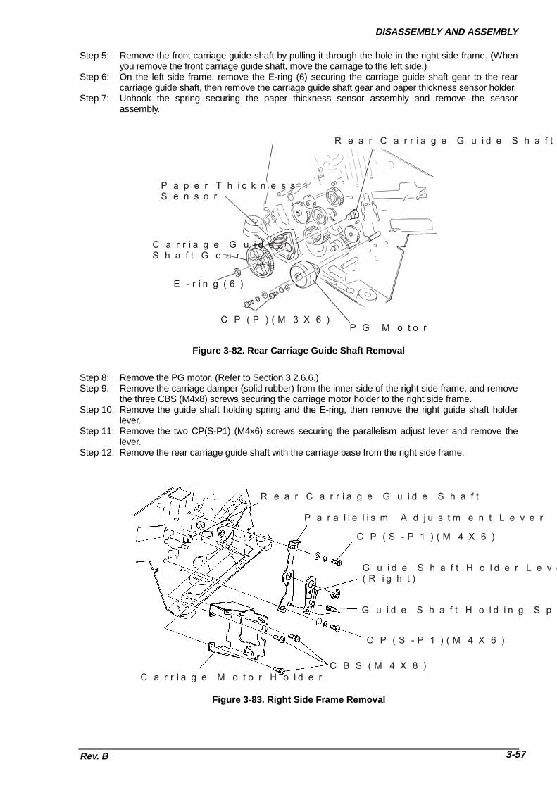
DISASSEMBLY AND ASSEMBLY
Rev. B 3-57
Step 5: Remove the front carriage guide shaft by pulling it through the hole in the right side frame. (Whenyou remove the front carriage guide shaft, move the carriage to the left side.)
Step 6: On the left side frame, remove the E-ring (6) securing the carriage guide shaft gear to the rearcarriage guide shaft, then remove the carriage guide shaft gear and paper thickness sensor holder.
Step 7: Unhook the spring securing the paper thickness sensor assembly and remove the sensorassembly.
P a p e r T h i c k n e s s S e n s o r
C a r r i a g e G u i d e S h a f t G e a r
E - r i n g ( 6 )
C P ( P ) ( M 3 X 6 )P G M o t o r
R e a r C a r r i a g e G u i d e S h a f t
Figure 3-82. Rear Carriage Guide Shaft Removal
Step 8: Remove the PG motor. (Refer to Section 3.2.6.6.)Step 9: Remove the carriage damper (solid rubber) from the inner side of the right side frame, and remove
the three CBS (M4x8) screws securing the carriage motor holder to the right side frame.Step 10: Remove the guide shaft holding spring and the E-ring, then remove the right guide shaft holder
lever.Step 11: Remove the two CP(S-P1) (M4x6) screws securing the parallelism adjust lever and remove the
lever.Step 12: Remove the rear carriage guide shaft with the carriage base from the right side frame.
R e a r C a r r i a g e G u i d e S h a f t
P a r a l l e l i s m A d j u s t m e n t L e v e r
C P ( S - P 1 ) ( M 4 X 6 )
G u i d e S h a f t H o l d e r L e v e r( R i g h t )
G u i d e S h a f t H o l d i n g S p r i n g
C P ( S - P 1 ) ( M 4 X 6 )
C B S ( M 4 X 8 )C a r r i a g e M o t o r H o l d e r
Figure 3-83. Right Side Frame Removal

DFX-8500
Rev. B3-58
ASSEMBLING POINT
When you install the front carriage guide shaft, tighten the screws while pushing the shaft toward theplaten.
ADJUSTMENT REQUIRED
When you assemble the carriage mechanism, perform the following adjustments:
• Carriage timing belt tension adjustment (described in Section 4.1.2)
• Carriage guide shaft parallelism adjustment (described in Section 4.1.5 and Section 4.1.6)
• Platen gap motor value (platen gap) adjustment (described in Section 4.1.7)
• Bidirectional printing adjustment (described in Section 4.1.8)

DISASSEMBLY AND ASSEMBLY
Rev. B 3-59
3.2.6.23 Paper Support Assembly Removal
Step 1: Disassemble the carriage mechanism and remove all the parts related to the carriage. (Refer toSection 3.2.6.22.)
Step 2: Referring to the exploded diagram in the Appendix, remove the paper support assembly.
ADJUSTMENT REQUIRED
When you install the paper support assembly, perform the following adjustments:
• Carriage timing belt tension adjustment (described in Section 4.1.2)
• Carriage guide shaft parallelism adjustment (described in Section 4.1.5 and Section 4.1.6)
• Platen gap motor value (platen gap) adjustment (described in Section 4.1.7)
• Bidirectional printing adjustment (described in Section 4.1.8)

DFX-8500
Rev. B3-60
3.2.6.24 3.2.6.21 PF Drive Roller Removal
Step 1: Remove the platen. (Refer to 3.2.6.10)Step 2: Remove the CR motor. (Refer to Section 3.2.6.20)Step 3: Remove the left side frame gears. (Refer to Section 3.2.6.16)Step 4: Referring to the exploded diagram in the Appendix, remove the PF driver roller.
ADJUSTMENT REQUIRED
When you install the PF drive roller, perform the following adjustments:
• Carriage timing belt tension adjustment (described in Section 4.1.2)
• Carriage guide shaft parallelism adjustment (described in Section 4.1.5 and Section 4.1.6)
• Platen gap motor value (platen gap) adjustment (described in Section 4.1.7)
• Bidirectional printing adjustment (described in Section 4.1.8)

CHAPTER 4ADJUSTMENT
4.1 PRINTER MECHANISM ADJUSTMENTS ............................................................4-1 4.1.1 PG Motor Backlash Adjustment........................................................................................... 4 -1
4.1.2 Carriage Timing Belt Tension Adjustment .......................................................................... 4-2
4.1.3 Tractor Wire Spring Tension Adjustment........................................................................... 4-3
4.1.4 Pull Tractor Sensor Position Adjustment............................................................................ 4-4
4.1.5 Carriage Guide Shaft Parallelism Adjustment .................................................................... 4-5
4.1.6 Platen Angle Adjustment ................................................................................................. ..... 4-9
4.1.7 Platen Gap Motor Value Adjustment.................................................................................. 4-12
4.1.8 Measurement Seeking and Bi-directional Printing Adjustment...................................... 4-15


ADJUSTMENT
Rev. B 4-1
4.1 PRINTER MECHANISM ADJUSTMENTSThis section describes the printer mechanism adjustments for the DFX-8500. Whenever the printer isdisassembled and the printer parts mentioned in this section are replaced or repaired, perform theappropriate adjustments to ensure proper printer operation. Perform adjustments before assembling theprinter.
4.1.1 PG Motor Backlash AdjustmentIn the PG motor backlash adjustment, the PG motor pinion gear must mesh smoothly with the PGtransmission gear cog. If the pinion gear is poorly aligned or the pinion gear and cog are too tight, printeroperation is noisy or the character density is incorrect.
;�If the PG motor backlash is too tight, PG motor doesn’t rotate smoothly and the panel indicates “E3.”
Step 1: Loosen the two screws securing the PG motor to the left side frame. (Refer to Section 3.2.6.4)Step 2: Make sure the PG motor pinion gear is properly aligned with the PG transmission gear cog. Move
the PG motor until there is 0.05 to 0.15 mm (0.002 to 0.01 inches) between the PG motor pinion gearand PG transmission gear cog. Then tighten the two screws.
CAUTION
P G T r a n s m i s s i o n G e a r
0 . 0 5 - 0 . 1 5 m m
P G M o t o rP i n i o n G e a r
S c r e w s P G M o t o r
Figure 4-1. PG Motor Mounting Position Adjustment

DFX-8500
Rev. B4-2
4.1.2 Carriage Timing Belt Tension AdjustmentThe carriage timing belt tension must be adjusted when any carriage mechanism part (such as the CR motor,belt pulley, or carriage timing belt) is disassembled. Remove the printer mechanism before performing thisadjustment. (Refer to Section 3.2.6)
;�Before performing this adjustment, carefully secure the printer mechanism because a 7 kg (15.4 lb.)force is applied to it when the tension lever is pulled in the horizontal direction.
Step 1: Loosen the three tension adjustment screws on the CR motor. Confirm that the carriage timing belt isattached properly and that no load is applied to it.
Step 2: Insert the tension gauge hook through the hole in the tension lever.Step 3: Pull the tension gauge horizontally to apply a 7 kg (15.4 lb.) force.Step 4: Move the belt left and right while pulling the tension gauge, and move the motor pulley slightly.Step 5: Tighten the three CPS(M4x10) tension adjustment screws and secure them while the 7 kg (15.4 lb.)
force is applied.Step 6: Finish tightening the three tension adjustment screws with 12 Kg cm torque.
CAUTION
7 0 0 0 g f + 2 0 0 g f
C P S ( M 4 X 1 0 )
Figure 4-2. Carriage Timing Belt Tension Adjustment

ADJUSTMENT
Rev. B 4-3
4.1.3 Tractor Wire Spring Tension AdjustmentThis section describes the tractor wire spring tension adjustment. If the spring is not adjusted properly, paperjams may occur, because the continuous paper tension (in the horizontal direction) is incorrect. When youremove the front or rear tractor assembly, perform this adjustment.
Step 1: Remove the printer mechanism. (Refer to Section 3.2.6)Step 2: Release the release levers for the tractor sprockets on the front.Step 3: At the left side frame, loosen the CBS(M4 X 8) screws securing the wire holding plate (L).Step 4: Pull the tractor wire left to make correct tension to the tractor wire, wire holding plate ( R) and the tip
of the gold seal are 5 mm (0.2 inches) apart.Step 5: Fix the CBS(M4 X 8) screws on the wire holding plate (L).Step 6: As the same manner, adjust the tractor spring tension for the rear tractor.
T r a c t o r W i r eT e n s i o n S p r i n g
T e n s i o n S p r i n g
G o l d S e a l
5 m m
T r a c t o r W i r e
W i r e H o l d i n g P l a t e ( R )
1 0 - 1 5 m m
W i r e H o l d i n g P l a t e ( L )
T r a c t o r W i r e
C B S ( M 4 X 8 )
T r a c t o r R e l e a s e L e v e r
P u l l , a d j u s t , f i x , a n d c u t h e r e .
Figure 4-3. Tractor Wire Tension Adjustment (Front)

DFX-8500
Rev. B4-4
4.1.4 Pull Tractor Sensor Position AdjustmentThis section describes the pull tractor sensor position adjustment. If the sensor position is incorrect, thesensor is always on. When you replace or disassemble the platen, rear paper guide, platen roller shaft,tension roller shaft, or pull tractor sensor, perform this adjustment. Figure 4-4 illustrates the pull tractor sensorposition adjustment.
When you assemble the pull tractor sensor or rear paper guide, check the following items:
• Verify that the pull tractor sensor lever is touching the rear paper guide frame, but the sensor isoff.
• Make sure the distance between the sensor lever and sensor switch is approximately 2 mm (.08inches).
( . 0 8 " )
L e f t S i d e F r a m e
S e n s o r S w i t c h
S e n s o r L e v e r
P u l l T r a c t o r s e n s o r
2 m m
Figure 4-4. Pull Tractor Sensor Position Adjustment

ADJUSTMENT
Rev. B 4-5
4.1.5 Carriage Guide Shaft Parallelism AdjustmentThe rear carriage guide shaft must be parallel to the platen. If it is not, printing may be abnormal becausepaper is not fed evenly at the left and right sides of the platen. A paper jam may occur. This adjustment isrequired when the rear carriage guide shaft is removed during carriage mechanism disassembly, theparallelism adjust lever is moved, or the platen is removed. Do not remove the printer mechanism (If removethe printer mechanism from the lower case, the adjust value will be out of order when you reassemble theprinter mechanism to the lower case.) Also, it is necessary to remove the tension roller shaft beforeperforming this adjustment. (Refer to Section 3.2.6.7.)
The parallelism is adjusted so that the difference between the distances (from the rear carriage guideshaft to the platen measured at the two positions shown in Figure 4-5) is less than + 0.015 mm. Sincethis value is extremely small, you must use the two dial gauges, dial gauge base, and dial gaugemaster supplied by EPSON. Do not adjust the parallelism using any other method.
;� Dial gauges (x 2) #F610 (Part No. B1019466)
;�Dial gauge base #F611 (Part No. B1019467)
;�Dial gauge master #F612 (Part No. B1019468).
Before performing the carriage guide shaft parallelism adjustment, you must assemble the two dial gauges,dial gauge base, and dial gauge master to form one tool. Follow these steps:
Step 1: Attach the two thumb screws for the dial gauge base to the dial gauge master. To eliminate any playbetween the dial gauge base and the dial gauge master, pull the tie band to secure the dial gaugebase and the dial gauge master before you securing the thumb screws.(Do procedure with two men.)
Step 2: Attach a dial gauge needle to the surface of the dial gauge master (approx. 2.00 mm depth), thentighten the hexagonal screw securing the dial gauge to the dial gauge base.
CAUTION
Figure 4-5. Set Dial Gauge to Dial Gauge Base
1. Attach the gauge needle to the master surface.
2. Tighten the hexagonal screw.
Figure 4-6. Dial Gauge Set Up 1

DFX-8500
Rev. B4-6
Step 3: Attach the another needle to the master surface, APPROX. 2.00 mm depth, then correspond to theanother gauge measure, and tighten the hexagonal screw.
Step 5: Set the black marker to the "0" position.
2. Attach the gauge needle to the master surface, then correspond to the another gauge measure.
3. Tighten the hexagonal screw.
Figure 4-7. Dial Gauge set Up 2
Figure 4-8. Black Marker to “0” Position Setting

ADJUSTMENT
Rev. B 4-7
Step 6: Remove a CP(PS)(M3X6) screw securing the timing belt holder to the timing belt, then remove thetiming belt holder.
Step 7: Remove the paper bail assembly. (Refer to Section 3.2.6.5.)Step 8: Remove the tension roller shaft. (Refer to Section 3.2.6.7.)Step 9: Remove the printhead with the mask-less holder. (Refer to Section 3.2.1.)Step 10: Attach the dial gauge base with the dial gauge in the same way as you attach the print head.
Then you attach this tool to the carriage, tighten the two thumb screws while you pulling the dialgage base toward you.
Step 11: Using the carriage guide shaft gear, adjust the gauge mounting position so that the tips of thegauges (portions A and B in the Figure 4-10) are securely attached to the platen.
C P ( P S ) M 3 X 6 )
T i m i n g B e l t H o l d e r
C a r r i a g e
C a r r i a g e G u i d e S h a f t ( R e a r )
Figure 4-9. Carriage Plate Removal
010
10 20
20
30
30010
10 20
20
30
30
P l a t e n
D i a l G a u g e B a s e
D i a l G a u g e M a s t e r
D i a l G a u g e x 2
T i e b a n d
A B
C a r r i a g e
Carria
ge G
uide Shaft (R
)
Carria
ge G
uide Shaft G
ear
R e f e r t o F i g u r e 4 - 1 0 a .
Figure 4-10. Dial Gauge Attachment
S t o p p e r
P G T r a n s m i s s i o n G e a r
C R G u i d e S h a f t G e a r
Figure 4-10a. CR Guide Shaft Gear Positioning

DFX-8500
Rev. B4-8
Step 12: Measure the distance between the platen and the carriage guide shaft on the left side. Thenmeasure the distance between the platen and the rear carriage guide shaft on the right side, andcompare these values.(Figure4-11 shows the measurement position and the parallelism adjustlever operation.)
Note: When you shift the carriage manually, do not touch the both dial gauges. Rotate the carriage motor pulley.
Step 13: If the distance measured at the left side is greater than that measured at the right side, move theparallelism adjust lever in the direction shown by the white arrow in Figure 4-9. If the distancemeasured at the left side is less than that measured at the right side, move the lever in thedirection shown by the black arrow.
Notes 1: The carriage guide shaft moves as shown in Figure 4-8. For example, when the parallelism adjust lever is moved in the direction of the black arrow, the distance betweenthe right side of the platen and printhead nose narrows a little bit.
Notes 2: The carriage guide shaft moves as shown in Figure 4-8. When the parallelism adjust leveris moved in the direction of the black arrow, the distance between the right side of theplaten and print head nose narrows a little bit.
Step 14: Repeat steps 11 and 12 until the distance between the distance measured at the two positions isless than + 0.015 mm.(The #F610 dial gauge matches the + "15" notches.)
Step 15: When the distance is within the specified range, tighten the two CP(PS)(M4 X 6) screws securingthe parallelism adjustment lever. Then measure the distances again, as described in step 11.
Step 16: If the distance between the measured distances is within the specified range, apply screw lock to the two screws.(Refer to Section 6.2 for lubrication and adhesive application instructions.)
Step 17: Go to Section 4.1.6 platen angle adjustment.
C a r r i a g e P a r a l l e l i s m
C a r r i a g e M o t o r
M o t o r P u l l e y
7 0 m m 7 0 m m
010
10 20
20
30
30
R i g h t S i d e F r a m e
A d j u s t L e v e r
Figure 4-11. Carriage Guide Shaft Parallelism Adjustment
Carriage Guide Shaft Rear
Parallelism Adjustment Lever
CP(PS)(M4X6)
Guide Shaft Holder Lever(Right)
Guide Shaft Holding Spring
CP(PS)(M4X6)
CBS(O)(M4X8)Carriage Motor Holder
Figure 4-12. Parallelism Adjustment Lever Operation

ADJUSTMENT
Rev. B 4-9
4.1.6 Platen Angle AdjustmentThis section describes the platen angle adjustment. The platen must be at a right angle to the carriageassembly. This adjustment is required when the platen is removed or replaced or when the two hexagonalscrews securing the platen to both side frames are loosened. Do not remove the printer mechanism from thelower case. (If remove the printer mechanism from the lower case, the adjust value will be out of order whenyou reassemble the printer mechanism to the lower case.) Also, it is necessary to remove the tension rollershaft be fore performing this adjustment. (Refer to Section 3.2.6.7)
The parallelism is adjusted so that the difference between the distances (from the rear carriage guideshaft to the platen measured at the two positions shown in Figure 4-7) is less than + 0.015 mm. Sincethis value is extremely small, you must use the two dial gauges, dial gauge base, and dial gaugemaster supplied by EPSON. Do not adjust the parallelism using any other method.
;� Dial gauge #F610 (Part No. B1019466)
;�Dial gauge base #F611 (Part No. B1019467)
;�Dial gauge master #F612 (Part No. B1019468).
Step 1: Perform the carriage guide shaft parallelism adjustment. (Refer to section 4.1.5) After the adjustment is finished, leave the dial gage unit on the carriage.
Step 2: Remove the pull tractor sensor.(Refer to Section 3.2.6.10.)Step 3: Loosen (but do not remove) the two hexagonal screws securing the platen stay to both side frames.
CAUTION
H e x a g o n a l S c r e w s ( M 4 X 8 )
P l a t e n S t a y ( R )P l a t e n S t a y ( L )P o s i t i o n i n g T a b
P o s i t i o n i n g T a b
S i d e F r a m e R S i d eS i d e F r a m e L S i d e
Figure 4-13. Loosing Hexagonal Screws

DFX-8500
Rev. B4-10
Step 4: Using the carriage guide shaft gear, attach the both dial gauge needles to the platen surface.(Theneedle doesn’t reach the end of the stroke).
Step 5: Measure the angle difference about three position such as figure below.(Using the CR motorpulley to move the carriage with the dial gauge toward the right side. See Figure 4-11.)
C a r r i a g e g u i d e S h a f t G e a r
S i d e F r a m e ( L )
C a r r i a g e G u i d e S h a f t
P l a t e n
A t t a c h b o t h n e e d l e s .
R e f e r t o F i g u r e 4 - 1 0 a .
Figure 4-14. Attaching Two Needles to Platen Surface
010
10 20
20
30
30010
10 20
20
30
30
Platen
010
10 20
20
30
30010
10 20
20
30
30010
10 20
20
30
30010
10 20
20
30
30
Center Position70 mm 70 mm
Figure 4-15. Measuring Angle Difference 1

ADJUSTMENT
Rev. B 4-11
Step 6: If the angle difference of two values are more than + 0.015 mm, loosen (but do not remove) the twohexagonal screws securing the platen stay to both side frames, then change the platen angle slowllyand manually.)
Step 7: Tighten two hexagonal screws securing the platen stay to both side frames.
After perform the adjustment, confirm the value of platen parallelism again. When this value is out oforder, readjust the platen parallelism and the platen angle adjustment until the value to be correct.
P l a t e nB i t A
B i t B
( A n g l e A d j u s t m e n t M e t h o d )
U p
D o w n
Figure 4-16. Measuring Angle Difference 2
CAUTION

DFX-8500
Rev. B4-12
4.1.7 Platen Gap Motor Value AdjustmentThis section describes how to measure the parameter (ALPHA and BETA values) for the PG mechanismunit. Since the ALPHA and BETA values are unique to each mechanism unit, it is written on the label asshown in Figures 4-17 and 4-18, so that it can be confirmed at glance. Be sure to perform this measurementand correct the value written on the label because the value is necessary when the other units (board,printhead) are changed.
;�This measurement is important because it determines the platen gap, so be sure to use theexclusive thickness gauge set and tension gauge.
� Thickness gauge (0.43 mm)
� Thickness gauge (0.80 mm)
� Tension gauge (200 g) : #F545 (EPSON Part No. B765114601)
;�Do not turn the printer off during adjustment.
� When adjusting the platen gap to narrower or wider using the Micro Feed (^) and Micro Feed (v)switches, be sure to adjust the gap by 1 step at a time.
;�After perform this adjustment, perform the Bi-Directional adjustment as explained in section 4.1.8.
CAUTION
A L P H A V a l u e P r i n t
P r i n t h e a d
Figure 4-17. ALPHA Value Print
S i d e F r a m e ( L e f t )
P r o d u c t i o n N o .F r a m e ( F r o n t )
5 m m o r l e s s
B E T A V a l u e
Figure 4-18. BETA Values Print

ADJUSTMENT
Rev. B 4-13
Step 1: Remove the paper, ribbon cartridge, and ribbon mask holder from the printer. Then confirm theALPHA value written on the print head nose.
Step 2: Close the top cover.
ALPHA Value Write Mode :Step 3: Turn the printer on while pressing the Tear Off, Micro Feed (v), and Front/Rear switches. At this
time the printer performs PG home position seek. and the carriage moves to the 15 column.Step 4: The panel indicates the current ALPHA adjustment value (Refer to Table 4-1.).Step 5: Write the ALPHA value written on the print head into the memory.
• Press the Micro Feed (v) switch to increment value by +1.• Press the Micro Feed (^) switch to decrement the value by -1.
Step 6: 1) When you finish the adjustment (such as you have replaced the print head.), press the LF/FFLoad SW, then the ALPHA value is written to the EEPROM and finish the adjustment mode.Then turn the power off and install the ribbon mask holder and the ribbon cartridge.
2) When you continue the BETA values write operation, press the Pause SW, then the ALPHAvalue is written to the EEPROM and enter to the BETA values write mode.
BETA Values Write Mode :Step 7: Open the top cover and inset the 0.43 mm thickness gauge into the space between the platen
and the print head nose. (At this time, never shift the print head. If done it, return to Step 3.)Step 8: Contact the tension gauge to the hole of the thickness gauge and pull it straight to the right.Step 9: Hold the thickness gauge gradually with the print head nose by pressing the below switch.
• Press the Micro Feed (v) switch to increment value by +1.• Press the Micro Feed (^) switch to decrement the value by -1.The panel indicates the current BETA3’ adjustment value (Refer to Table 4-1.).
Step 10: Set the BETA3’ value when the tension gauge indicates the 150 (135 - 165) gf, the tension gaugecan move to right in a degree.
Step 11: After complete BETA3’ adjustment, press Pause SW to enter next step.Step 12: Close the print head nose to the platen by pressing the below switch.
• Press the Micro Feed (v) switch to increment value by +1.• Press the Micro Feed (^) switch to decrement the value by -1The panel indicates the current BETA2 adjustment value (Refer to Table 4-1.).
Step 13: After complete BETA2 adjustment, press Pause SW to enter next step.Step 14: Inset the 0.43 mm thickness gauge into the space between the platen and the print head nose.Step 15: Hold the thickness gauge gradually with the print head nose by pressing the below switch.
• Press the Micro Feed (v) switch to increment value by +1.• Press the Micro Feed (^) switch to decrement the value by -1.The panel indicates the current BETA3 adjustment value (Refer to Table 4-1.).
Step 16: After complete BETA3 adjustment, press Pause SW to enter next step.Step 17: Inset the 0.80 mm thickness gauge into the space between the platen and the print head nose.Step 18: Hold the thickness gauge gradually with the print head nose by pressing the below switch.
• Press the Micro Feed (v) switch to increment value by +1.• Press the Micro Feed (^) switch to decrement the value by -1.The panel indicates the current BETA4 adjustment value (Refer to Table 4-1.).
Step 19: After complete BETA4 adjustment, press Pause SW then all of measured BETA values writtento the EEPROM, and turn the printer power off.
Note: When either the measured BETA values (BETA2, BETA3, and BETA4) are out of range(Refer to Table 4-1.) or the below formula is not satisfied, the printer sounds five beepsand not written the values to the EEPROM.Formula: A1 = 0.43 / (BETA3 - BETA2) and 0.0134 < A1 < 0.0187
A2 = (0.80 - 0.43) / (BETA4 -BETA3) and 0.0115 < A2 < 0.0195Step 20: Install the ribbon mask holder and the ribbon cartridge.

DFX-8500
Rev. B4-14
Table 4-1. BETA Values AdjustmentBeta No. Reference Thickness Gauge Allowed Value Default Value*1)
BETA 3' 0.43 mm with 150gf pull - -BETA 2 0.00 mm 367 - 419 408BETA 3 0.43 mm 405 - 437 435BETA 4 0.80 mm 418 - 475 461*1: When EEPROM is reset.
P l a t e n
T e n s i o n G a u g e
T h i c k n e s s G a u g e( B E T A 3 ' = 0 . 4 3 m m )
1 3 5 - 1 6 5 g f
Figure 4-19. Thickness Gauge Setting Method

ADJUSTMENT
Rev. B 4-15
4.1.8 Measurement Seeking and Bi-directional Printing AdjustmentThe purpose of this adjustment is to correct the printer mechanism parameters which control bi-directionalprinting. Be sure to perform this adjustment when required. If this adjustment is not performed correctly, bi-directional printing may be miss-aligned, or, in the worst case, the carriage might operate incorrectly. Beforeperforming this adjustment, be sure to that the following adjustment are completed correctly.
4.1.2 Carriage Timing Belt Tension Adjustment4.1.5 Carriage Guide Shaft parallelism Adjustment4.1.6 Platen Angle Adjustment4.1.7 Platen Gap Motor Value Adjustment
The parameters to be written to the EEPROM on the C204 Main board in this adjustment are as follows:
1) Measurement seeking2) Print head flight time adjustment value3) Bi-directional printing alignment value for each speed mode, Super Draft, Draft, and NLQ
;�If the DIP-SW "3-5" is set to the IBM mode (On), it can not perform the Bi-D adjustment. Therefore,when you perform the Bi-D adjustment, set the DIP-SW"3-5" to Off.
;�When replace the C204 Main board, the ALPHA and BETA values are not written into the memory(In reality, "0" value is installed.) on the Main board. Since this reason, (Since PG is too large) it cannot print the each current value to the paper. Due to this, Perform the platen gap value adjustmentbefore perform this adjustment.

DFX-8500
Rev. B4-16
E N D
S T A R T
T u r n t h e p o w e r S W o n w h i l e p r e s s i n g M i c r o F e e d ^ a n d M i c r o F e e d v S W s .
T h e p r i n t e r p e r f o r m s c a r r i a g e m e a s u r e m e n t s e e k i n g a u t o m a t i c a l l y . ( I t g o e s t o O N L I N E s t a t u s a f t e r t h i s o p e r a t i o n . )
T u r n t h e p r i n t e r p o w e r o f f .
M o u n t t h e r i b b o n c a r t r i d g e .
Figure 4-20. Carriage Measurement Seeking

ADJUSTMENT
Rev. B 4-17
Y e s
S T A R T
T u r n t h e p o w e r S W o n w h i l e p r e s s i n g T e a r O f f , M i c r o F e e d ^ , a n d F r o n t / R e a r S W s .
S e t t h e 1 5 " f a n f o l d p a p e r a t F r o n t o r R e a r t r a c t o r a n d l o a d t h e p a p e r b y p r e s s i n g L F / F F L o a d S W o r F r o n t / R e a r S W .
" P G A l p h a = A A A " i s p r i n t e d .
1 . " P G B e t a 1 = B B B , P G B e t a 2 = C C C , P G B e t a 3 = D D D , P G B e t a 4 = E E E " i s p r i n t e d .2 . P a n e l d i p l a y s t h e c u r r e n t f l i g h t t i m e a d j u s t m e n t v a l u e ( R e f e r t o T a b l e 4 - 2 . ) .3 . " F l i g h t T i m e = F F F " i s p r i n t e d .
T h e p r i n t e r p r i n t s t h e t e s t p r i n t p a t t e r n w i t h t h e c u r r e n t f l i g h t t i m e s e t t i n g v a l u e .R e f e r t o F i g u r e 4 - 2 2 .
D o e s t h e o d d ( 1 s t a n d , 3 r d ) a n d e v e n ( 2 n d a n d 4 t h ) l i n e s v e r t i c a l a l i g n m e n t i s O K ?
C h a n g e t h e f l i g h t t i m e a d j u s t m e n t v a l u e . D e c l e m e n t 1 0 s t e p s : T o p o f F o r m S W o n c e . D e c l e m e n t 1 s t e p : P u s h M i c r o F e e d ^ S W o n c e . I n c l e m e n t 1 0 s t e p s : T e a r O f f S W o n c e . I n c l e m e n t 1 s t e p : P u s h M i c r o F e e d v S W o n c e .
P a n e l d i p l a y s t h e c u r r e n t f l i g h t t i m e a d j u s t m e n t v a l u e .
P r e s s t h e C o p y S W .
T h e c u r r e n t f l i g h t t i m e a d j u s t v a l u e i s s t o r e d i n t h e E E P R O M .
G o t o B i - D . A d j u s t m e n t M o d e .
T u r n t h e p r i n t e r p o w e r o f f .
M o u n t t h e r i b b o n c a r t r i d g e .
P r e s s t h e P a u s e S W .N o
E N D
Figure 4-21. Flight Time Adjustment

DFX-8500
Rev. B4-18
Table 4-2. LED indication and Adjustment Value ComparisonLED*1) Off On*2)
Ribbon (Bi-d. adjustment) (PG adjustment)
+ (positive) 300
(negative)400
Pause 10Top of Form 20Tear Off 30Copy 40Pitch ��� ���
���
506070
Font �� ��
8090
7 Segment*3) 0 to 9*1) �: off, �: On*2) Indicates 2nd column.*3) Indicates 1st column.
4 0 C O L . 4 0 C O L .5 6 C O L .
F l i g h t T i m e + X X X
Figure 4-22. Test Print Pattern
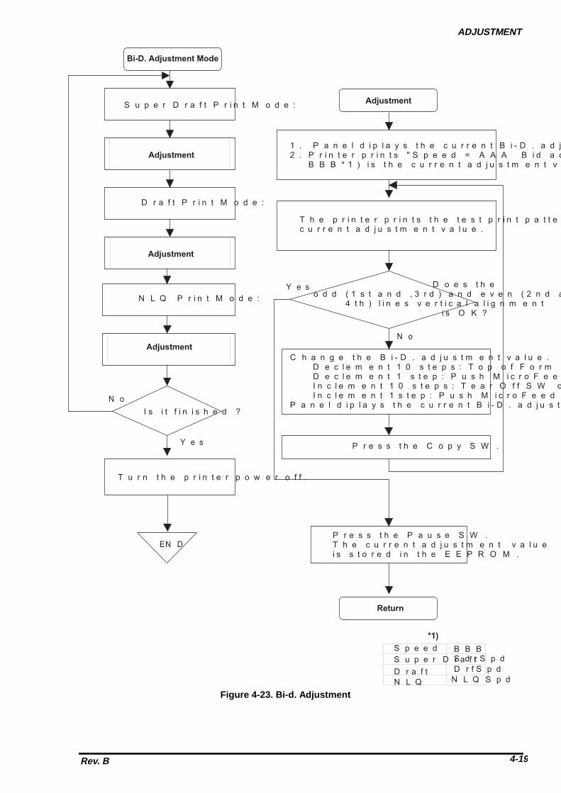
ADJUSTMENT
Rev. B 4-19
B i - D . A d j u s t m e n t M o d e
S u p e r D r a f t P r i n t M o d e :
N o
Y e s
1 . P a n e l d i p l a y s t h e c u r r e n t B i - D . a d j u s t m e n t v a l u e .2 . P r i n t e r p r i n t s " S p e e d = A A A B i d a d j u s t = B B B " . B B B * 1 ) i s t h e c u r r e n t a d j u s t m e n t v a l u e .
D o e s t h e o d d ( 1 s t a n d , 3 r d ) a n d e v e n ( 2 n d a n d 4 t h ) l i n e s v e r t i c a l a l i g n m e n t i s O K ?
T h e p r i n t e r p r i n t s t h e t e s t p r i n t p a t t e r n w i t h t h e c u r r e n t a d j u s t m e n t v a l u e .
C h a n g e t h e B i - D . a d j u s t m e n t v a l u e . D e c l e m e n t 1 0 s t e p s : T o p o f F o r m S W o n c e . D e c l e m e n t 1 s t e p : P u s h M i c r o F e e d ^ S W o n c e . I n c l e m e n t 1 0 s t e p s : T e a r O f f S W o n c e . I n c l e m e n t 1 s t e p : P u s h M i c r o F e e d v S W o n c e .P a n e l d i p l a y s t h e c u r r e n t B i - D . a d j u s t m e n t v a l u e .
A d j u s t m e n t
R e t u r n
A d j u s t m e n t
D r a f t P r i n t M o d e :
A d j u s t m e n t
N L Q P r i n t M o d e :
A d j u s t m e n t
N o
I s i t f i n i s h e d ?
E N D
T u r n t h e p r i n t e r p o w e r o f f .
P r e s s t h e P a u s e S W .T h e c u r r e n t a d j u s t m e n t v a l u e i s s t o r e d i n t h e E E P R O M .
S u p e r D r a f tS p e e d B B B
S d r S p dD r f S p dN L Q S p d
D r a f tN L Q
* 1 )
P r e s s t h e C o p y S W .Y e s
Figure 4-23. Bi-d. Adjustment


CHAPTER 5TROUBLESHOOTING
5.1 PROBLEM ISOLATION..........................................................................................5-1
5.2 SELF DIAGNOSTIC FUNCTION............................................................................5-2
5.3 TROUBLESHOOTING ...........................................................................................5-3


TROUBLESHOOTING
Rev. B 5-1
5.1 TROUBLESHOOTING INFORMATIONThe information in this chapter makes troubleshooting easier to perform by listing various problems that canoccur and providing possible solutions.
Note: For this printer, no special tools are necessary for troubleshooting to the unit level, with theexception of a digital multi-meter. Some component-level troubleshooting may require anoscilloscope.
5.1.1 Error MessagesThe DFX-8500 indicates errors using beeps. Table 5-1 lists fatal errors.
Table 5-1. Fatal Error Information
Fatal Error 7-segmentLED *1)
Beeper *2) Description Note*3)
CR motorcircuitshortage error
1 - • The isolation resistance in the CRmotor is too low.
Auto power offafter 12 seconds
Cutter error 2 - - • Optional cutter cable is not connectedfirmly.
• Optional cutter is defective.
Auto power offafter 12 seconds
Platen gaperror
3 - - - • The PG home sensor is broken.• The PG motor is broken.• The parallelism adjustment is
incorrect.• PG adjustment values are incorrect.• PG backlash is too tight.
Auto power offafter 12 seconds
Carriage lockerror
4 - - - - • The carriage is locked.• The interlock switch doesn’t close
exactly.• The parallelism adjustment is
incorrect.• PG adjustment values are incorrect.
Auto power offafter 12 seconds
Carriage loadmeasurementerror
6 - - - - - - • PW sensor is defective.• The CR motor is defective.• The CR encoder sensor is defective.
Auto power offafter 12 seconds
Head fan error 7 - - - - - - - • The head fan driver IC is shorted.• The head fan of the print head is
defective.
Head power offimmediately
Head circuitshortage error
8 - - - - - - - - • The print head driver IC is shorted.• The coil of the print head is defective.
Head power offimmediately
RAM checkerror
9 - - - - - - - - - • DRAM of C204 MAIN board isdefective.
Auto power offafter 12 seconds
Paper memorysetting error
a - - - - - - - - - - - -
EEPROM datacompare error
b - - - - - - - - - - - • EEPROM on the C204 MAIN boardis defective.
Tractor changeerror
c - - - - - - - - - - --
• Tractor select mechanism isdefective.
Auto power offafter 12 seconds
Watch dogerror
d • C205 MAIN board has trouble. Auto power offafter 12 seconds
Note 1: The 7 segment LED indicates error No. and “E” alternately.Note 2: The descriptions “.”and “-“ show how the beeper sounds.
“.”: Beeper sounds 100 ms and interval is 100 ms.“-“ : Beeper sounds 500 ms and interval is 100 ms.
Note 3: Turn the printer power off while the 7 segment LED are on, or the printer shuts power down automatically. You can’t turn the printer back on for 5 minutes after the printer shuts power down automatically

DFX-8500
Rev. B5-2
5.1.2 Bypassing Interlock Switch and Cover Open SensorTo print with the top cover open or removed, you need to bypass the interlock switch and cover open sensorbecause these sensors automatically disable printing when the top cover is open.
The interlock switch and cover open sensor consists of an assembly. To bypass the interlock switch and thecover open sensor,1. remove the left side cover,2. make the short circuit connectors for the interlock switch and cover open sensor connectors,3. insert the short circuit connectors for the interlock switch and cover open sensor connectors.
C o v e r O p e n S e n s o r
I n t e r l o c k S W .
C N 3
C o n n e c t o rJ u n c t i o n B o a r d
C 2 0 4 M A I N B o a r d
W h i t e : 2 - p i n
R e d : 3 - p i n
Figure 5-1. Interlock Switch Assembly Location
C N 3
C o n n e c t o rJ u n c t i o n B o a r d
C 2 0 4 M A I N B o a r d
W h i t e : 2 - p i nS h o r t C i r c u i t C o n n e c t o r
Figure 5-2. Bypassing Interlock Switch and Cover Open Sensor

TROUBLESHOOTING
Rev. B 5-3
5.1.3 Coil ResistanceThe following table provides the coil resistance for the motor, head fan, plunger, and printhead.
Table 5-2. Motor, Fan, Plunger, and Printhead Coil ResistancePart Coil Resistance
CR motor 1.66 ohms + 10 %PF motor 2.80 ohms + 10 % at 25oCRF motor 150 ohms + 10 % at 25oCPG motor 250 ohms + 18 ohms at 25oCHead fan 61 ohms + 4.3 ohms at 25oCPlunger 9 ohms + 5 % at 25oC
Printhead 2.93 ohms + 0.2 ohms at 25oC
Head Cable Board
Head Cable Protection Sheet
Head FPC
Double-sided Adhesive TapeShield Cable
123
45
C
B
A
Figure 5-3. Disconnect Printhead FPC

DFX-8500
Rev. B5-4
FPC A
FPC B
FPC C
Load Pattern
: Head coil GND side: Head coil P/S side: Head thermistor
MA : Fan motor phase AMB : Fan motor phase BMC : Fan motor commonMT : Fan motor thermistor
PWD : Paper width sensor+5V : +5 VDCENCA: Encoder AGND : GNDHT : Head thermistor
P/S : Power supply (+37 VDC)ENCB: Encoder B
Figure 5-4. Printhead Coil Resistance

TROUBLESHOOTING
Rev. B 5-5
1. The printer does not operate when power is turned on.
END
Replace the C204 MAIN board, C204 DRV board, and/or C204 DRV-B board.
Is the AC input voltage normal?
No
Yes
Use the correct AC voltage.
Has fuse F1 on the C204 power
supply board blown?
Yes
No
When youturn on power
again, does thenew fuse also
blow?
No
Yes
Replace the C power supply board.
No
Measure the output voltage fromthe C power supply board.
Is the output voltage
normal?
Yes
No
Yes
Is the fault corrected?
See Section 5.3 torepair the printermechanism.
Check all motors, solenoid, printhead,and drivers using a multimeter.
Are they within normal
range?
Yes
No Replace bad motor, solenoid, or printhead. If driver also is bad,replace at the same time.
END
Yes
Is the fault corrected?
Retest
Is the problem
fixed? No
END
Yes
No
Does theprinter beep
before it dies?
No
Yes
Check Table 5-1, ErrorCodes.
START
204
Replace the fuse F1 anddisconnect CN2, CN3, and CN4 on the C204 power supply Board.
Reconnect CN2, CN3, and CN4and turn on the printer.
204

DFX-8500
Rev. B5-6
2. Carriage operation is abnormal.
END
START
No
Yes
Are the connectors listed in
NOTE 1inserted securely?
Reinsert the connectors.
Is the fault corrected?
No
Yes
Manually move the carriage to see if
movement is smoothor not.
Not smooth
Refer to Section 5.3, Repairof the Printer Mechanism.Perform repair necessary.
No
Yes
Is the fault corrected?
END
Smooth
END
Check theCR motor and CRmotor drivers using
a multimeter.OK?
No
If the motor is bad, replace.If drivers are bad, replace atthe same time.
Yes Is the fault corrected?
No
Yes
NOTE 1: Check the following connectors: Junction board connector to interlock switch Junction board connector to CR motor Head junction board connectors to printhead CN4 of C204 MAIN board to head junction board
Replace the C204 MAIN board and/orC204 DRV board.

TROUBLESHOOTING
Rev. B 5-7
3. Carriage operation is normal, but the self-test is printed incorrectly (1/3).
Reinsert correctly.
Yes
START
No
Yes
No Is the fault corrected?
END
END
Perform the self-test.
Are the connectors listed in NOTE 1
inserted securely?
No
Yes
Perform the bidirectionalprinting adjustment.
No
Yes
Check printhead cablecontinuity. Visually checkprinthead pins. Replaceany bad part.
Is the fault corrected?
Yes
No
A
Does the printer perform self-test ?
Is thereany dot missing or dragging ?
NOTE 1: Check the following connectors: Three head junction board connectors to printhead CN1 of C204 MAIN board to head junction board CN2 of C204 MAIN board to C204 DRV-B board CN1 of C204 DRV-B board to printer mechanism

DFX-8500
Rev. B5-8
3. Carriage operation is normal, but the self-test is printed incorrectly (2/3).
Refer to Section 5.3, Repair of the Printer Mechanism.
Print OK?
.
If the printhead driversare OK, replace theprinthead.
Check the printhead drivers.
NoIs the printhead resistance
correct?
No
Yes
Are thedrivers OK?
A
Yes
No
Yes
B
Is the print OK?
No
If the printhead driversare OK, replace theprinthead.
Check the printhead drivers.
NoAre thedrivers OK?
Yes
END
Refer to Section 5.3 Repair of the Printer Mechanism.
B
Yes
Check the print head coil resistance.
Replace the C204 MAIN and./or C204 DRV-B board.
Replace the C204 MAIN and./or C204 DRV-B board.
Replace the C204 MAIN and./or C204 DRV-B board.

TROUBLESHOOTING
Rev. B 5-9
3. Carriage operation is normal, but the self-test is printed incorrectly (3/3).
B
Yes
Perform bidirectionaladjustment.
END
No
Is the print correct?
Go back to Section 5.3 Repairof the Printer Mechanism, andcheck for other problems.
Perform bidirectionaladjustment.
END

DFX-8500
Rev. B5-10
4. Printing is normal, but paper feeding is abnormal.
Are the drivers shorted or
open?
Load the paper correctly.
START
Yes
Is the paper loaded
correctly?
Yes
Is PFmotor coilresistancecorrect?
Yes
No
Yes
END No
Is the print OK?
Refer to Section 5.3 Repair of the Printer Mechanism.
No
Replace thePF motor.
Check the resistance of the PF motor coils and check the PF motor drivers.
Is the
motor resistance OKand are the drivers
OK?
No
Refer to Section 5.5, Repair of the Printer Mechanism.
Are the drivers shorted or
open?
Yes
Perform final printing of self-test.
END
No Is the print OK?
Yes
Refer to Chapter 4and perform the PGmotor backlashadjustment.
END
No Is the print OK?
Refer to Chapter 4 and perform the PG motor backlashadjustment.
END
END
Yes
Whenyou move the PF
motor manually, does itmove smoothly?
Refer to Section 5.3 Repair of the Printer Mechanism.
Perform final printing of self-test.
No
No
Replace the C204 DRV boardand the PF motor.
Replace the C204 MAIN board and/orC204 DRV board.

TROUBLESHOOTING
Rev. B 5-11
5. Panel unit operation is abnormal.
Replace the C PNL board.
Is the fault corrected?
Replace the C MAIN board.
Do theswitches work
correctly?
Reinsert connector CNcorrectly.
START
Do the buttons work?
END
END
Replace the C MAIN board.
Is the fault corrected?
Yes No
No
Yes
No END
Replace the C PNL board.
No
No
Yes
Yes
Yes
END
END
Using a multimeter, checkthe switches on theC PNL board.
5
204
204
204
204
204
Is CN5between the C204 MAIN and C204 PNL board connected correctly?

DFX-8500
Rev. B5-12
6. Data sent by the host computer is printed incorrectly.
Note : The flowchart below assumes the host computer is operating normally.
Replace C MAIN board.
Check the cable connectionfrom the host computer.
Troubleshoot printer using theprevious flowcharts.
Run the self-test.
START
Is the self-test printed correctly? No
Yes
Which I/F are you using?
Built-in Parallel
Serial orOptional
Yes
Replace cable.
No
END END
Yes
If youare using a
serial I/F, is yourcable a null modem
cable?
No
Yes
Replace C MAIN board.
END
If you areusing a Type B
optional I/F for a network, isthe network configured
correctly?
Not using serial.
Yes
Replace Type B interface.
END
Reconfigure network.
END
No
Set switchescorrectly.
END
No
Are the DIPswitches set correctly?(See Tables 1-16,1-21, 1-22,and 1-23.)
204
204
Is your parallel cable is a shielded, twisted-pair cable less than 2 m, and does it work with another printer?

TROUBLESHOOTING
Rev. B 5-13
5.2 CIRCUIT BOARD REPAIRThis section provides detailed troubleshooting methods to isolate components in the power supply or on themain board. This information is for use by service personnel who repair to the component level.
The table below provides causes, checkpoints, and solutions for different power supply circuit problems. Thecheckpoints include waveforms for normal operation. By referring to the checkpoints, determine the defectivecomponent. Then perform the proper repair. The table provides the following four columns:
��Symptom: Check this column for a list of common printer problems.��Cause: Use this column to identify possible causes that could produce this symptom.��Checkpoint: Follow the troubleshooting checks in this column to isolate your problem.<��Solution: Repair the printer using the instructions in this column.
5.2.1 C204 PSB/PSE Board RepairTable 5-4 indicates majour components which is used for the C204 PSB/PSE board and Table 5-4 shows theC204 PSB/PSE board component level troubleshooting.
Table 5-4. C204 PSB/PSE Board Main Parts ListLocation Description
DB1 Diode bridgeTY1 TRIAC
QF101 Switching FET for VP1 and VP2QF201 Switching FET for VP3 and +5 VDCIC101 PWM switching controllerIC204 +5 V regulator IC
Table 5-5. C204 PSB/PSE Board Component Repair 1/3Symptom Cause Checkpoint Solution
No DC voltage is presentat the output . (Fan onthe power supply boarddoesn’t rotate at all.)
PD signal is HIGH (sentfrom the main board).
Measure the signal levelof the PD signal at CN4.
Wait until the printerprints again.Replace the E05B36 onthe C204 MAIN board.
The DRERR signal isHIGH.
Measure the signal levelof the DRERR signal atCN4.
Replace the printheaddriver on the C204 MAINboard and/or C204 DRV-B board.
CL signal is HIGH. Measure the signal levelof the CL signal at CN4.
Wait until the printerprints again.Replace the E05B36 onthe C204 MAIN board.
Fuse F1 blowsimmediately afterreplacement.
The line filter circuit isdefective.
Check if any of pinsC1-C5 or R1 is shortingthe AC line.
Replace the abnormalelement.

DFX-8500
Rev. B5-14
Table 5-5. C204 PSB/PSE Board Component Repair 2/3Symptom Cause Checkpoint Solution
The +37 VDC (VP1 /VP2) line is dead.
The main switching FETsQF101 is defective.
Observe the voltagewaveform between thedrain side and GND.
Replace QF101.
IC101 is defective. Pin 5 (FB) must be HIGHthen observe the voltagewaveform between pin 2(VOUT) and pin 12(GND) of IC101.
Replace IC101.
The +37 VDC (VP3) lineis dead.
The main switching FETsQF201 is defective.
Observe the voltagewaveform between thedrain side and GND.
Replace QF201.
Q201 is defective. Observe the voltagewaveform between thecollector side and GND.
Replace Q201.
Q202 is defective. Observe the voltagewaveform between thecollector side and GND.
Replace Q202.

TROUBLESHOOTING
Rev. B 5-15
Table 5-5. C204 PSB/PSE Board Component Repair 3/3Symptom Cause Checkpoint Solution
The 5 VDC line isdefective.
IC204 is defective. Check the voltage level at pin 10 (V1)and pin5 (GP).
Replace IC204.
Observe the drive waveform at pin 8(VO) and pin 5 (GP).
Replace IC204 orZD211.
37 VDC line(VP1/VP2) isabnormal.
IC102 is defective. (Ifthis IC is defective, itcannot monitor the 37VDC lines, andprinting operationbecomes abnormal.),
When the input voltage of the minusport (pin 6 for VP1 and pin2 for VP2) isless than 1.3 VDC, the comparatoroutputs a HIGH signal.
Replace IC203.
37 VDC line (VP3)is abnormal.
IC203 is defective. (Ifthis IC is defective, itcannot monitor the 37VDC lines, and motoroperations becomeabnormal.),
When the input voltage of the plus portis bigger than 1.3 VDC, the comparatoroutputs a HIGH signal.
Replace IC203.

DFX-8500
Rev. B5-16
5.2.2 C204 MAIN/DRV/DRV-B Boards RepairTable 5-6 indicates major components which is used for the C204 MAIN/DRV/DRV-B boards and Table 5-7shows the C204 MAIN/DRV/DRV-B boards component level troubleshooting.
Table 5-6. C204 MAIN/DRV/DRV-B boards Component Repair 1/7Symptom Cause Checkpoint Solution
The printer doesnot operate at all.
The DRERR signalwas sent to the C204power supply board(HIGH level turns offthe power supply).
Check the logic level of the DRERRsignal at CN10 or check the VP1 andVP2 voltage.
Replace the headdriver on the C204MAIN board (VP1)or C204 DRV-Bboard (VP2).
The PD signal wassent to the C204power supply board.(HIGH level turns offthe power supply)
Check the logic level of the PD signalduring power on and verify the voltagewaveform for the head driver. (Refer tothe head driver waveform figure,above.)
Replace the headdriver or gate array.
The reset circuit is notoperational (for logic).
Check the logic level at pin1 (VOUT) ofIC13.
Replace IC13.
The driver circuitsdon’t operate atall.
The pull up voltageVX is not generated.
When the collector of Q15 is highCheck the logic level at collector of Q14(VX) (When the collector of Q15 ishigh, VX is HIGH..
Replace Q15.
Serial interface isdead.
The level converter ICis defective.
Check the signal level change betweenin and out port of the IC9.
Replace IC9.

TROUBLESHOOTING
Rev. B 5-17
Table 5-6. C204 MAIN/DRV/DRV-B boards Component Repair 2/7Symptom Cause Checkpoint Solution
The printer doesnot operate at all.
The control ROM isdefective.
Confirm that the PROM is inserted thesocket correctly.
Replace IC5.
The gate array (IC1)is defective.
Check pin 86 (D0)of IC1 for a changein the signal (HIGH or LOW).
Replace IC1.
The CPU (IC2) isdefective
Look at the oscillator at either pin 27(x1) or pin 28 of the CPU.
Replace CRU1 orIC1
The DRAM (IC14) isdefective
Observe pin 2 (D0) of IC14 for achange in the signal (HIGH or LOW).
Replace IC14.

DFX-8500
Rev. B5-18
Table 5-6. C204 MAIN/DRV/DRV-B boards Component Repair 3/7Symptom Cause Checkpoint Solution
The carriageoperatesabnormally.
IC1 on the C204MAIN board isdefective.
Check the signals for the carriagemotor phases at pins 204 (CRA), 205(CRB), 206 (CRC), and 5 (CRD) of IC1
Replace IC1.
Q16, Q17, Q18, orQ19 on the C204MAIN board isdefective.
Check the signals for the carriagemotor phases at collectors Q16 (CRA),Q17 (CRB), Q18 (CRC), and Q19(CRD).
Replace Q16, Q17,Q18, or Q19.
IC1 is doesn’t work. Check the voltage level between Anodeand Kathode of ZD2 is APPROX. 6.2 V.
Replace ZD2, Q34,or Q35.
IC1 on the C204 DRVboard is defective.
Check the signals for the carriagemotor phases at pins 14 (IN_A) and 10(OUT1) of IC1..
Replace IC1.
. Measure the voltage level at pins 10(OUT1) and 5 (GP) of IC1 when thecarriage is operating. (The normalvoltage level is approximately 37VDC.),
Replace IC1.
IC3 on the C204 DRVboard is defective.
Observe the waveform at pin 1 of IC3. Replace IC3.

TROUBLESHOOTING
Rev. B 5-19
Table 5-6. C204 MAIN/DRV/DRV-B boards Component Repair 4/7Symptom Cause Checkpoint Solution
The carriageoperatesabnormally.
The carriage encodersensor is defective.
Observe the carriage encoder sensoroutput signal at pins 4 (ENCA) and 3(ENCB) of CN4 on the C204 MAINboard.
Replace thecarriage encodersensor.
Carriage operation isunstable (due to alack of motor torque).
Check the switching waveform for Q5,Q6, and Q7.
Replace theabnormal transistor.

DFX-8500
Rev. B5-20
Table 5-6. C204 MAIN/DRV/DRV-B boards Component Repair 5/7Symptom Cause Checkpoint Solution
Paper feeding isabnormal.
The CPU IC2) on theC204 MAIN board isdefective.
Check the PF motor phase drivesignals at pins 2 - 5 of IC2.
Replace IC2.
IC2 on the C204 DRVboard is defective.
At IC2, check the output signals forpins 2 (OUT_A), 3 (OUTXA), 6(OUT_B), and 7 (OUTXB).
Replace IC2.
Ribbon feeding isabnormal.
The CPU IC2) on theC204 MAIN board isdefective.
Check the RF motor phase drivesignals at pins 6 - 9 of IC2.
Replace IC2.
The commonswitching transistor onthe C204 DRV boardis defective.
Check the collector voltage of Q21. Replace Q20 orQ21.
The phase switchingtransistor on the C204DRV board isdefective.
For transistors Q22 - Q25, observe theinput signal from the CPU (base) andthe output signal (collector).
if there is no outputsignal, replace theabnormal transistor.
Fuse F1 on the C204DRV board isdefective.
Check if fuse F1 is defective. Replace F1.

TROUBLESHOOTING
Rev. B 5-21
Table 5-6. C204 MAIN/DRV/DRV-B boards Component Repair 6/7Symptom Cause Checkpoint Solution
The head fanoperation isabnormal.
IC1 on the C204MAIN board isdefective.
Observe the PG motor phase signal atpins 163 (FANA) and 164 (FANAX) ofIC1.
Replace IC1.
Q10 or Q11 on theC204 MAIN board isdefective.
Observe the head fan phase drivevoltage level for pins 25 (HFANA) and17 (HFANB) of CN1. (The normalvoltage is approximately 37 VDC.)
Replace Q10 orQ11.
The PG motoroperatesabnormally.
IC1 on the C204MAIN board isdefective.
Observe the PG motor phase signal atpins 10 (PGA), 12 (PGB), 14 (PGAX),and 13 (PGBX) of IC1.
Replace IC1.
The commonswitching transistor onthe C204 DRV boardis defective.
Check the collector voltage of Q11. Replace Q10 orQ11.
The phase switchingtransistor on the C204DRV board isdefective.
For transistors Q12 - Q15, observe theoutput signal (collector).
if there is no outputsignal, replace theabnormal transistor.
Fuse F2 on the C204DRV board isdefective.
Check if fuse F2 is defective. Replace F2.
The PG sensor isdefective.
Observe the PG sensor output signal atpins 35 (PGENCA) and 34 (PGENCB)of CN14.
Replace the PGsensor.
The PG homeposition sensor isdefective.
Observe the PG HP sensor signal levelfor pin 36 (PGHOME) of CN14.(PG home = LOW level; other = HIGHlevel.)
Replace the PGhome positionsensor.
The plunger isdefective.
Fuse F3 is defective Check if fuse F3 is defective. Replace F3.
IC1 on the C204MAIN board isdefective.
When paper is loaded into the printer,look at the switching signal at pins 16(PLP) and 17 (PLN)of IC1.
Replace IC1.
Plunger drivetransistor on the C204DRV board isdefective.
Observe the Q31 collector voltage atpaper loading.
Replace Q31, Q30,or Q32.

DFX-8500
Rev. B5-22
Table 5-6. C204 MAIN/DRV/DRV-B boards Component Repair 7/7Symptom Cause Checkpoint Solution
The self-test isprinted incorrectly
IC1 on the C204MAIN board isdefective.
Observe the output signal at pins 136-181 of IC1.
Replace IC1.
The head driver FETson the C204 MAINand/or C204 DRV-Bboards are defective.
Observe the voltage waveform at theeach FET drain side.
Replace theabnormal FET.
The CPU (IC2) on theC204 MAIN board isdefective.
Observe the signals at pins 38 (PTS1)and 42 (PTS2) of the IC2
Replace the IC2.

TROUBLESHOOTING
Rev. B 5-23
5.2.3 Printer Mechanism RepairThe table below describes how to isolate problems with the printer mechanism. To replace or adjust printermechanism parts, refer to Chapter 3, Disassembly and Assembly, and Chapter 4, Adjustments. If asymptom recurs following a repair attempt, look for other possible causes and solutions in the table below.
Table 5-7. Printer Mechanism Repair 1/4Symptom Cause Checkpoint Solution
The CR motordoes not operate.
The transport lockingbracket (used to holdthe carriage in placewhen the printer ismoved) has not beenremoved.
Verify that the transport locking brackethas been removed.
Remove bracket.(Refer to Section3.1.)
Foreign objects arelodged in the gears orelsewhere (e.g. paperdust on the carriageencoder belt) in themechanism.
Manually move the carriage to see ifthe motor rotates.
Remove any foreignobjects.
The CR motor isdefective.
Measure the coil resistance of the CRmotor. It should be approximately 1.66ohms + 10 %.
Replace the CRmotor.
The carriage timingbelt is defective.
Manually check the carriage timing belttension.
Perform the carriagetiming belt tensionadjustment, asdescribed in Section4.1.2.
The carriage guideshaft parallelismvalue is incorrect.
Check whether the carriage movessmoothly when moved manually.(Check that foreign objects are notlodged in the printer mechanism.),
Perform the carriageguide shaftparallelismadjustment, asdescribed in Section4.1.5.
The CR encodersensor is defective.
Check the waveform for the carriageencoder signal. (Refer to Table 5-6.),
Replace the CRencoder sensor.
The carriage encoderbelt is damaged orcovered with dust.
Check the encoder belt (below thecarriage timing belt).
Replace or clean thecarriage encoderbelt.
The carriagemoves, but noprinting isperformed.
The printhead FPCcommon wires arebroken.
Check the continuity of the commonwires for the printhead FPC.
Replace the FPC.

DFX-8500
Rev. B5-24
Table 5-7. Printer Mechanism Repair 2/4Symptom Cause Checkpoint Solution
A particular dotdoes not print.
The printhead isdefective.
Measure the printhead coil resistance.(Refer to Figure 5-4 for details.)
Replace theprinthead.
Check whether a dot wire is worn. Replace theprinthead.
The print is toolight or printdensity is notuniform.
The printhead isdefective.
Check if the tip of a dot wire is worn. Replace theprinthead.
The parallelism valueis incorrect.
Print density differs at the right and leftsides of the page (darker on one sidethan the other).
Perform theparallelismadjustment, asdescribed in Section4.1.5.
The platen gap valueis incorrect.
Print density is too light even the newribbon cartridge is mounted.
Perform theparallelismadjustment, asdescribed in Section4.1.5.
Printing isperformed, but theprinter does notfeed paper ordoes not feed itcorrectly.
Foreign objects arelodged in the paperpath.
Visually check the paper path. Remove any foreignsubstances.
The PF motor is notdriving the gearproperly.
Check whether the PF motor piniongear rotates smoothly when rotatedmanually
Check backlashbetween PF motorpinion gear andpaper feed reductiongear.
The PF motor isdefective.
Measure coil resistance for the PFmotor. (The correct resistance isapproximately 2.8 ohms + 10%.) Alsocheck the PF motor drivers.
Replace the PFmotor, and if driversare bad, replacemain board at thesame time
The ribbon feed(RF) motor doesnot operate.
The ribbon cartridgeis defective.
Remove the ribbon cartridge, rotate it,and check whether it feeds the ribbonnormally.
Replace the ribboncartridge.
Foreign objects arecaught in the gears.
Check whether the ribbon driving gearrotates when the cartridge is movedmanually.
Remove any foreignobjects or replacedamaged ribbonfeed mechanismpart (the ribbon feedselect gear, ribbonfeed transmissiongear, or ribbon feedgear).
..

TROUBLESHOOTING
Rev. B 5-25
Table 5-7. Printer Mechanism Repair 3/4Symptom Cause Checkpoint Solution
The RF motordoes not operate.
The parallelism valueis incorrect.
Check whether the carriage movessmoothly when moved manually.(Check that foreign objects are notlodged in the printer mechanism.)
Perform theparallelismadjustment, asdescribed in Section4.1.5.
The RF motordoes not operate.
The RF motor isdefective.
Check the coil resistance of the RFmotor. (It should be about 150 ohms +10 %.)
Replace the RFmotor.
The PG motordoes not operate.
The backlash value isincorrect.
Check whether the carriage guide shaftrotates smoothly when rotatedmanually.
Loosen the 2 screwssecuring the PGmotor to the left sideframe. Then adjustthe backlashbetween the PGmotor pinion gearand the carriageguide shaft gear, asdescribed in Chapter4, Adjustments.
The PG encodersensor is defective
Check the output signal of the PGencoder sensor. (Refer to Table 5-6.)
Replace the PGencoder sensor.
The encoder plate isdefective.
Check whether the encoder plate isbroken or stained.
Replace the PGmotor or clean theencoder plate.
The PG home sensoris defective
Check the continuity of the sensor.(Check the status of the two microswitches.),
Replace the PGhome sensor (microswitch type).
The PG motor isdefective.
Check the coil resistance of the PGmotor. (It should be about 250 ohms +18 ohms.)
Replace the PGmotor.
Printing continuespast the end ofthe paper.
The front, rear, or topPE sensor isdefective.
Check the PE sensor. Replace the PEsensor.
When paper jams,the printer doesnot beep.
The paper jam sensoris defective.
Check the paper jam sensor. Replace the paperjam sensor.
Ribbon Jam erroroccurs even theribbon is fedcorrectly.
Ribbon jam sensor isdefective.
Check the ribbon jam sensor. Replace the ribbonjam sensor.

DFX-8500
Rev. B5-26
Table 5-7. Printer Mechanism Repair 4/4Symptom Cause Checkpoint Solution
Printing occursoutside the paperwidth.
The PW sensor isdefective.
Check the PW sensor. Replace the PWsensor.
The paper bailassembly doesnot work.
The plunger isdefective.
Check the coil resistance of theplunger. (It should be about 9 ohms.)
Replace the plunger.
Continuous paperbecomescrumpled at thefront or reartractor assembly.
The tension value ofthe tractor wire springis incorrect.
The distance between the frame andthe seal securing the white line shouldbe about 3 mm (0.12 inches).
Perform the tractorwire spring tensionadjustment, asdescribed in Section4.1.3.
The tractor select(front or rear)function is notworking.
The tractor selectsensor is defective.
Check the continuity of the tractorselect sensor.
Replace the tractorselect sensor.
The tractor selectgear is disconnectedfrom the tractor selectcam.
Visually check the tractor select gearholder.
Join the tip of thetractor select lever tothe tractor selectgear holder.

CHAPTER 6MAINTENENCE
6.1 PREVENTIVE MAINTENENCE..............................................................................6-1
6.2 LUBRICATION AND ADHESIVE APPLICATION...................................................6-1


MAINTENANCE
Rev. B 6-1
6.1 PREVENTIVE MAINTENANCETo keep the printer in good condition, regularly clean the case exterior (using denatured alcohol) and vacuumthe mechanism's interior to remove dust and paper debris. After cleaning the printer, check that it isadequately lubricated, as described in Section 6.2, below. Before returning the printer to the customer,inspect the springs and paper feed rollers and check that the printer operates properly.
;�Disconnect the printer from the external AC power source before performing maintenance. Do notuse thinner, trichloroethylene, or ketone-based solvents on the plastic components of the printer.
Note: It is necessary to clean the carriage encoder belt periodically. When this printer is returnedfor service, clean the surface of carriage encoder belt.
6.2 LUBRICATION AND ADHESIVE APPLICATIONEPSON recommends that the printer be lubricated at the points illustrated in Figures 6-2, 6-3, and 6-4 usingEPSON lubricants O2 and G26. These lubricants have been extensively tested and found to comply withneeds of the printer. Refer to Table 6-1 for information on lubricants O2 and G26. Table 6-2 lists theappropriate lubricant for each point. Make sure the parts to be lubricated are clean before applying lubricant.Also avoid applying too much lubricant because it may damage related parts.Adhesive application is necessary at the points indicated in Table 6-3 when parts are disassembled orreplaced. EPSON recommends Neji Lock #2 (G) adhesive be applied to the points indicated in Figures 6-2,6-3, and 6-4. Avoid allowing excess adhesive to overflow onto related parts.
Table 6-1. Recommended Lubricants
Type Name Quantity Part No. AvailabilityGrease G26 40 g B702600001 EOil O2 40 cc B710200001 EAdhesive Neji Lock #2 (G) 1000 g B730200200 ENote: E = EPSON exclusive product (not commercially available)
;�Do not apply too much lubricant because it may create stains or cause the mechanism tomalfunction.
CAUTION
CAUTION

DFX-8500
Rev. B6-2
Table 6-2. Lubrication Points
Ref. No. Ref. Figure Lubrication Point Lubricant(1) 6-3 Carriage oil pad ring (on both left and right sides of carriage) O2(2) 6-3 Carriage oil pad (under the carriage head cable holder), O2(3) 6-3 Hole holding the tip of the rear carriage guide shaft (in both left
and right side framesG26
(4) 6-3 Both edges of the rear carriage guide shaft G26(5) 6-3 Parallelism adjustment lever (contact point with the rear carriage
guide shaftG26
(6) 6-4 Rear carriage shaft holding lever (contact point with the rearcarriage guide shaft)
G26
(7) 6-3 Carriage guide shaft (on the both front and rear shafts) G26(8) 6-4 Platen roller shaft holder (contact point with the platen roller) G26(9) 6-4 Paper bail gear G26(10) 6-2 Shafts of paper feed gears (shafts on the left frame) G26,O2(11) 6-2 Paper feed gears (gears on the left frame) G26(12) 6-2 Tension pulley (pulley shaft and hook for the tension pulley spring) G26(13) 6-3 Fulcrum point for the paper bail shaft and plunger G26(14) 6-4 Platen gap motor pinion G26(15) 6-3 Carriage guide shaft gear G26(16) 6-3 Ribbon feed gears G26(17) 6-3 Tractor select cam G26
Table 6-3. Adhesive Application Points
Ref. No. Ref. Figure Adhesive Application Point Adhesive(25) 6-3 Tractor tension wire Neji Lock #2 (G)
Figure 6-1. Correct Adhesive Application

MAINTENANCE
Rev. B 6-3
Figure 6-2. Lubrication and Adhesive Diagram 1

DFX-8500
Rev. B6-4
Figure 6-3. Lubrication and Adhesive Dia gram 2

MAINTENANCE
Rev. B 6-5
Figure 6-4. Lubrication and Adhesive Diagram 3


APPENDIX
A.1 CONNECTOR PIN ASSIGNMENTS ..................................................................... A-1
A.2 CIRCUIT DIAGRAMS ........................................................................................... A-9
A.3 COMPONENT LAYOUT...................................................................................... A-21
A.4 CONNECTOR JUNCTION BOARD CONNECTORS.......................................... A-27
A.5 PART LIST.......................................................................................................... A-28
A.6 EXPLODED DIAGRAMS .................................................................................... A-31


APPENDIX
Rev. B A-1
A.1 CONNECTOR PIN ASSIGNMENTS
Figure A-1 illustrates the interconnection of the primary components. Table A-1 summarize the descriptionand sizes of the connectors.
CN
1(3
)
CN5(2)
CN
3(1
2)
CN
2(6
)C
N4
(8)
Fan
C204 PSB/PSE
CN
3(2
)C
N4
(4)
CN
5(1
4)
CN
9(7
)
CN
1(3
0)
CN2(20)
C204 DRV-B
CN
1(3
0)
CN3(20)
CN2(8)
CN8(8)
CN6(6)
CN12(36)CN13(7)
IEEE1284
EIA-232D
CN11(36)
TYPE-B CN
10
(8)
CN7(12) CN14(50x2) CN16(7)
CN15(6)
CN2(7)
CN1(6)
C204 SUB
C204 MAIN
C204 DRV
CN
2(5
0)
CN
3(6
)
CN1(50x2)
Printer Mechanism
C204 PNL
CN1(7) CN2(7)
Cover Open Sensor
CR Encoder
Junction Board
Printhead
Paper CutterUnit
AC Input
Figure A-1. Cable Connection

DFX-8500
Rev. BA-2
Table A-1. Board Connector SummaryConnector Connection Pin Number Table to ReferC204 MAIN BoardCN1 => Mechanism (Print head) 30 pins Table A-2CN2 => C204 DRV-B board 20 pins Table A-3CN3 => Cover Open 2 pins Table A-4CN4 => Mechanism (Carriage encoder) 4 pins Table A-5CN5 => Panel unit 14 pins Table A-6CN6 => C204 PSB/PSE board 6 pins Table A-7CN7 => C204 PSB/PSE board 12 pins Table A-8CN8 => C204 DRV-B board 8 pins Table A-9CN9 => Optional paper cutter 7 pins Table A-10CN10 => C204 PSB/PSE board 8 pins Table A-11CN11 => Optional Type-B I/F card 36 pins Table A-12CN12 => IEEE-1284 I/F 36 pins Tables 1-10 an 1-11CN13 => EIA 232D I/F 7 pins Table 1-12CN14 => C204 DRV board 50 pins X 2 Table A-13CN15 => C204 SUB board 6 pins Table A-14CN16 => C204 SUB board 7 pins Table A-15C204 DRV BoardCN1 => C204 MAIN board 50 pins X 2 Table A-13CN2 => Printer mechanism 50 pins Table A-16CN3 => C204 PSB/PSE board 6 pins Table A-17C204 DRV-B BoardCN1 => Mechanism (Printhead) 30 pins Table A-18CN2 => C204 MAIN board 6 pins Table A-9CN3 => C204 MAIN board 20 pins Table A-3C204 PSB/PSE boardCN1 => AC inlet 3 pins Table A-19CN2 => C204 MAIN board 6 pins Table A-7CN3 => C204 MAIN (CN7) and C204 DRV
(CN3) boards12 pins Tables A-8 and A-17
CN4 => C204 MAIN board 8 pins Table A-11CN5 => Cooling fan motor 2 pins Table A-20

APPENDIX
Rev. B A-3
Table A-2. C204 MAIN Board Connector CN1Pin Signal Name I/O Function
1 P+10 O Printhead pin #102 P-10 O GND3 P+12 O Printhead pin #124 P-12 O GND5 P+16 O Printhead pin #166 P-16 O GND7 P-17 O GND8 P-9 O GND9 P+17 O Printhead pin #1710 P-11 O GND11 P+11 O Printhead pin #1112 P-7 O GND13 P+9 O Printhead pin #914 P-7 O GND15 P+2 O Printhead pin #216 P+1 O Printhead pin #117 HFANB O HF motor phase B18 P-1 O GND19 FTMP I HF motor temperature20 P-2 O GND21 FANCOM O HF motor common22 HTMP I Print head temperature25 HFANA O HF motor phase A29 PWIDTH I Paper width signal30 +5 -23, 24,, 26, 27, 28 GND -
Table A-3. C204 MAIN Board Connector CN2Pin Signal Name I/O Function
1 HR3P O Print head coil #6 drive signal2 HR2P O Print head coil #4 drive signal3 HR9N O Print head coil #18 drive signal4 HR2N O Print head coil #4 drive signal5 HR7P O Print head coil #14 drive signal6 HR7N O Print head coil #14 drive signal7 HR9P O Print head coil #18 drive signal8 HR3N O Print head coil #6 drive signal9 HL8P O Print head coil #15 drive signal10 HL3N O Print head coil #5 drive signal11 HL8P O Print head coil #13 drive signal12 HL2N O Print head coil #3 drive signal13 HL8N O Print head coil #15 drive signal14 HL7N O Print head coil #13 drive signal15 HL3P O Print head coil #5 drive signal16 HL2P O Print head coil #3 drive signal167 HR4P O Print head coil #8 drive signal18 HR4N O Print head coil #8 drive signal19 HRSENS I Print head coil shortage monitoring20 HNSENS I Print head coil shortage monitoring
Table A-4. C204 MAIN Board Connector CN3Pin Signal Name I/O Function1 COPEN I Cover open status2 GND - -

DFX-8500
Rev. BA-4
Table A-5. C204 MAIN Board Connector CN4Pin Signal Name I/O Function1 GND -2 +5V -3 ENCB I CR encoder B phase pulse4 ENCA I CR encoder A phase pulse
Table A-6. C204 MAIN Board Connector CN5Pin Signal Name I/O Function1 LED_DATA O LED data2 LED_XLE O LED data latch3 LED_CLK O LED data clock5 LED_XOE O LED light enable6 BUZZER O Buzzer7 VCC - +5 VDC9 SW_INH O Switch data transfer inhibit9 SW_S/XL O Switch data shift/load select11 SW_DATA I Switch data13 SW_CLK O Switch data clock
4, 10, 912, 14 GND -
Table A-7. C204 MAIN Board Connector CN6Pin Signal Name I/O Function
1, 2, 3 VP1 - +37 VDC4, 5, 6 GP1 - GND for VP1
Table A-8. C204 MAIN Board Connector CN7Pin Signal Name I/O Function
1, 2, 3 VP2 - +37 VDC4, 5, 6 GP2 - GND for VP2
Table A-9. C204 MAIN Board Connector CN8Pin Signal Name I/O Function
8, 7, 6 VP1 - +37 VDC5, 4, 3 GP1 - GND for VP1
1 VX - +5 VDC switched by reset status2 GND -
Table A-10. C204 MAIN Board Connector CN9Pin Signal Name I/O Function1 CUTON O Cut signal2 CUTDIR I Cut direction3 CUTTER I Paper cutter mount/dismount4 CUTHPI I Cutter home position5 +5V -6 GND -7 RF I Reverse point signal
Table A-11. Digital Board Connector CN10Pin Signal Name I/O Function1, 2 +5V I3, 4 GND O5 DRERR O Head driver error signal6 /PD O Power down signal7 CL I Current limit signal8 SD I Power shutdown signal

APPENDIX
Rev. B A-5
Table A-12. C204 MAIN Board Connector CN11Pin Signal Name I/O Function
1, 2, 3, 4, 5, 6 +5 -7 BTXD O Transmit data8 XREADY O Ready9 BRXD I Receive data10 NC -11 BXRST O Reset signal12 INH O Inhibit signal output13 XCMDREQ I Command request signal14 XWRRDY I Write ready signal15 XRDREQ I Read request signal16 XWR O Write signal17 XRD O Read signal18 XCS O Chip select signal
19, 20, 21, 22, 23, 24 GND -25 A3 O Address bus 326 A2 O Address bus 227 A1 O Address bus 128 A0 O Address bus 029 D7 I/O Data bus 730 D6 I/O Data bus 631 D5 I/O Data bus 532 D4 I/O Data bus 433 D3 I/O Data bus 334 D2 I/O Data bus 235 D1 I/O Data bus 136 D0 I/O Data bus 0

DFX-8500
Rev. BA-6
Table A-13. C204 MAIN Board Connector CN14Pin Signal Name I/O Function1 VP3 - +37 VDC
2, 3, 4 GND -5, 6, 7, 8 +5 -
9, 10 VX - +5 VDC switched by reset status11 FAN O HF control signal12 PLN O Plunger N channel13 RFH/R O RF motor common14 RFC O RF motor C phase pulse15 RFA O RF motor A phase pulse16 PGD O PG motor D phase pulse17 PGB O PG motor B phase pulse18 CRINS I CR motor insulation resistance
monitoring19 CRI1 O CR motor current limit signal 120 CRCLM I CR motor current limit signal21 CRD O CR motor bridge D signal22 CRB O CR motor bridge B signal23 PFH/R O PF motor common24 PFC O PF motor C phase pulse25 PFA O PF motor A phase pulse
26, 27 GND -28 TR_SEL I Tractor select signal29 P_TRCT I Pull tractor mount/dismount30 P_JAM I Paper jam detection31 F_PE I Front paper end32 R_PE I Rear paper end33 T_PE I Top paper end34 PGENCB I PG encoder B signal35 PGENCA I PG encoder A signal36 PGHOME I PG home position37 RBJAM I Ribbon jam38 PLP O Plunger P channel39 RFD O RF motor bridge D signal40 RFB O RF motor bridge B signal41 PGH/R O PG motor common42 PGC O PG motor C phase pulse43 PGA O PG motor A phase pulse44 CRI2 O CR motor current limit signal 245 CRI0 O CR motor current limit signal 046 CRCLK O Clock pulse for CR motor driver47 CRC O CR motor bridge C signal48 CRA O CR motor bridge A signal49 PFD O PF motor bridge D signal50 PFB O PF motor bridge B signal
Table A-14. C204 MAIN Board Connector CN15Pin Signal Name I/O Function1 DIP1 I DIP SW1 status2 DIP2 I DIP SW2 status3 DIP3 I DIP SW3 status4 DIP4 I DIP SW4 status5 DIP5 I DIP SW5 status6 DIPCNT1 O DIP SW select port 1

APPENDIX
Rev. B A-7
Table A-15. C204 MAIN Board Connector CN16Pin Signal Name I/O Function1 DIPCNT2 O DIP SW select port 22 DIPCNT3 O DIP SW select port 33 DIPCNT4 O DIP SW select port 44 DIPCNT5 O DIP SW select port 55 DIPCNT6 O DIP SW select port 66 DIPCNT7 O DIP SW select port 77 DIPCNT8 O DIP SW select port 8
Table A-16. C204 DRV Board Connector CN2Pin Signal Name I/O Function
1, 3, 5, 8 VP3 - +37 VDC2 +5V -4 K - GND6 RBJAM Ribbon jam7 NC9 INTLOC - GND10 FANDRV CR fan drive11 INTLOC - GND12 INTLOC - GND13 GND -14 GP3 - GND for VP315 TR_SEL Tractor select signal16 PGHOME PG home position17 RFD RF motor phase D18 RFCOM RF motor common19 RFB20 RFA RF motor phase A21 PGCOM PG motor common22 RFC RF motor phase C23 PGA PG motor phase A24 PGD PG motor phase D25 PGC PG motor phase C26 PGB PG motor phase B27 PENCB PG encoder phase B28 PENCA PG encoder phase A29 R_PE Rear PE sensor30 T_PE Top PE sensor31 +5V -32 F_PE PE sensor front33 P_TRCT Pull tractor34 P_JAM Paper jam sensor35 PLGP Plunger36 GND -37 CRB CR motor phase B38 PLGN Plunger39 CRB O CR motor phase B40 PFA O PF motor phase A41 CRB O CR motor phase B42 PFB O PF motor phase B43 CRA O CR motor phase A44 PFC O PF motor phase C45 CRA O CR motor phase A46 PFD O PF motor phase D47 CRA O CR motor phase A
48, 49, 50 PFCOM O PF motor common
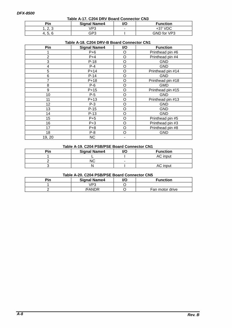
DFX-8500
Rev. BA-8
Table A-17. C204 DRV Board Connector CN3Pin Signal Name4 I/O Function
1, 2, 3 VP3 - +37 VDC4, 5, 6 GP3 I GND for VP3
Table A-18. C204 DRV-B Board Connector CN1Pin Signal Name4 I/O Function1 P+6 O Printhead pin #62 P+4 O Printhead pin #43 P-18 O GND4 P-4 O GND5 P+14 O Printhead pin #146 P-14 O GND7 P+18 O Printhead pin #188 P-6 O GMD9 P+15 O Printhead pin #1510 P-5 O GND11 P+13 O Printhead pin #1312 P-3 O GND13 P-15 O GND14 P-13 O GND15 P+5 O Printhead pin #516 P+3 O Printhead pin #317 P+8 O Printhead pin #818 P-8 O GND
19, 20 NC -
Table A-19. C204 PSB/PSE Board Connector CN1Pin Signal Name4 I/O Function1 L I AC input2 NC -3 N I AC input
Table A-20. C204 PSB/PSE Board Connector CN5Pin Signal Name4 I/O Function1 VP3 O2 /FANDR O Fan motor drive

APPENDIX
Rev. B A-9
A.2 CIRCUIT DIAGRAMSSee the following pages for the figures below:
Figure A-2. C204 MAIN Board Exploded Diagram
C204 MAIN
Figure A-3. C204 DRV Board Exploded Diagram
C204 DRV
Figure A-4. C204 DRV-B Board Exploded Diagram
C204 DRV-B
Figure A-5. C204 PSB Board Exploded Diagram
C204 PSB
Figure A-6. C204 PSE Board Exploded Diagram
C204 PSE


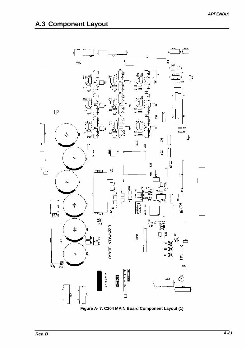
APPENDIX
Rev. B A-21
A.3 Component Layout
Figure A- 7. C204 MAIN Board Component Layout (1)

DFX-8500
Rev. BA-22
Figure A- 8. C204 MAIN Board Component Layout (2)

APPENDIX
Rev. B A-23
Figure A- 9. C204 DRV Board Component Layout (1)
Figure A- 10. C204 DRV Board Component Layout (2)

DFX-8500
Rev. BA-24
Figure A- 11. C204 DRV-B Board Component Layout (1)
Figure A- 12. C204 DRV-B Board Component Layout (2)

APPENDIX
Rev. B A-25
Figure A- 13. C204 PSB Board Component Layout

DFX-8500
Rev. BA-26
Figure A- 14. C204 PSE Board Component Layout

APPENDIX
Rev. B A-27
A.4 Connectors on the Connector Junction BoardSee the figure bellow for the connector arrangement on the connector junction board.
RB WG YB BW W
W
W
W
R
R
WR
B
W
B
to Plunger
to O
ptio
n Pull T
ractor Senso
r
to Rear PE Sen
sor
to Top
PE Sens
or
to PG Enco
der
to PG M
otor
to TS/R
F M
otor
to F/R Tractor Select Senso
r
to PG HP Senso
r
to Pap
er Ja
m Senso
r
to Front PE Senso
r
t o C R M o t o r
t o P a p e r F e e d M o t o r
t o C R M o t o r F a n
t o O p t i o n C u t t e r P o w e r
t o F a n
t o R i b b o n J a m S e n s o r
t o I n t e r l o c k S w i t c h
R : R e d
W : W h i t e
G : G r a y
Y : Y e l l o w
B : B l a c kC o n n e c t o r C o l o r s
2 p i n s 4 p i n s
2 pins
3 p i n s2 p i n s 2 p i n s 2 p i n s
4 pins
2 pins
2 pins
2 p i n s2 p i n s
6 p i n s
3 p i n s 3 p i n s 4 p i n s 6 p i n s 6 p i n s
Figure A- 15. Connectors on the Connector Junction Board

DFX-8500
Rev. BA-28
A.5 Part List
Table A-20. Part List (1/3)
No. Part Names No. Part Names100 HOUSING ASSY.,LOWER 163 SPACER,PS UNIT101 FRAME ASSY.,BOTTOM 164 LEAF SPRING,BASE FRAME102 COVER ASSY.,FRONT 165 COVER, DIP SWITCH103 HOUSING ASSY.,UPPER 166 COVER,CONNECTOR,UPPER ECW104 HOUSING ASSY.,TOP 167 C.B.(O)SCREW M3X8 F/ZN105 LOGO PLATE 168 CONNECTOR LOCK NUT for USA106 COVER,PAPER SUPPORT CONNECTOR LOCK NUT for others107 CAP,LOWER 170 DETECTOR,INTER LOCK 2.5,30108 COVER,REAR 171 BOARD ASSY.,SUB109 CAP,MAGNET 172 GROUNDING PLATE,MECHANISM110 HOUSING SUB ASSY.,TOP PLATE111 COVER,I/F 173 SHIELD PALTE,DRV-B112 MAGNET SUB ASSY.,TOP 174 SHIELD PLATE,DRV113 MECHANISM MOUNTING SCREW 175 GRONDING PLATE,BLACKET114 TOP COVER HINGE SCREW 176 MOUNT,DIP SWITCH115 HOLDER,CONTROL PANEL 200 BOARD ASSY.,MAIN116 HOUSING,LEFT 201 SCREW for USA117 HOUSING,RIGHT 201 SCREW for EUR, S.E.ASIA, ACEANIA118 COVER,TOP,SUB ASSY. 202 GUIDE,I/F BOARD119 COVER,PUSH TRACTOR SUB ASSY. 203 BRACKET,I/F120 PAPER SUPPORT SUB ASSY. 204 SHIELD PLATE,MAIN121 MOUNT,INTERLOCK 205 EARTH SPRING;B122 SHIELD PLATE 206 HARNESS123 C.B.S.(O) SCREW M3X8 212 C.B.S. SCREW M3X6124 C.B.(O) SCREW M4X6 500 PRINTER MECHANISM,M-3I60125 C.P. SCREW WITH S/WM3X16 501 FRAME ASSY.,LEFT126 C.F.S.SCREW M3X10 502 FRAME ASSY.,RIGHT127 C.B.B. SCREW M3X8 503 SOLENOID ASSY.,LD128 C.B.S. SCREW M3X8 504 MOTOR ASSY.,PG129 C.B.SCREW M3X12 505 MOTOR ASSY.,CR131 C.B.B. SCREW M3X10 506 FRAME,LOWER132 C.B.B. SCREW M3X12 507 FRAME,FRONT133 C.B.B.SCREW M4X10 508 MOTOR ASSY.,PF DC4.34134 C.B.B. SCREW M4X16 509 PULLY ASSY.,BELT135 C.P.(PS) SCREW M4X8 510 TENSION PULLEY ASSEMBLY136 C.B.S.(O) SCREW M4X8 511 FRAME ASSY.,MOTOR RF137 C.B.S.SCREW, 4X14 F/ZN 512 TRACTOR SELECT DETECTOR138 C.B.S. SCREW M3X6 513 MOTOR ASSY.,RF139 C.B.B. SCREW M3X10 514 RIBBON FEED SELECT GEAR140 C.F.B. SCREW M3X10 515 TRACTOR SELECT LEVER UPPER141 C.B.S. SCREW M3X4 516 TRACTOR SELECT LEVER LOWER142 METAL,TRANSPORT,FIX,LEFT 517 TRACTOR SELECT LEVER SPRING143 TRANSPORT LOCKING BRACKET 518 TRACTOR SELECT CAM144 FERRITE CORE RISC-4 519 TRACTOR SELECT TRANSMISSION145 FERRITE CORE GEAR146 FERRITE CORE RISC-8 520 RIBBON FEED TRANSMISSION GEAR147 C.B.S.(O) SCREW M3X6 521 PAPER THICKNESS DETECTOR148 +.ONEWAY PLA- LOCK,3X12,F/ZN 522 DETECTOR ASSY.,PGHP152 DAMPER SHEET 523 DETECTOR ASSY.,PULL TRACTOR153 DAMPER SHEET;B 524 PAPER GUIDE,UPPER159 SHAFT,FRONT,LOWER,RIGHT ECW 525 CARRIAGE ASSY.160 SHAFT,FRONT,LOWER,LEFT 526 LEAD WIRE161 LEVER ASSY.,LOCK,LEFT 527 BELT PULLEY HOLDER162 LEVER ASSY.,LOCK RIGHT 528 PLATEN ASSY.

APPENDIX
Rev. B A-29
Table A-20. Part List (2/3)
NO. Part Names NO. Part Names529 BOARD ASSY.,INTERMIT,HEAD 587 PLATEN ROLLER TRANSMISSION
GEAR530 BOARD ASSY.,INTERMIT,CARRIAGE 588 PLATEN ROLLER MIDDLE GEAR531 BOARD ASSY.,DETECTOR,PTS 589 TENSION ROLLER GEAR532 PAPER ASSY.,SUPPORT 590 PAPER BAIL GEAR533 ROLLER ASSY.,LOAD 591 PAPER BAIL LEVER534 BLUSH,ELIMINATION ELECTLIC 592 CUP SCREW M3X30535 DETECTOR ASSY.,PE,UPPER 593 TIMING BELT,PF536 DETECTOR ASSY.,PW 595 PAPER FEED REDUCTION GEAR537 HARNES,CUTTER 596 PAPER FEED MIDDLE GEAR538 HODLER,CR MOTOR 597 TRACTOR SELECT GEAR HOLDER539 MOUNT PLATE,CR MOTOR 598 TENSION PULLEY SPRING540 CABLE,BOARD,INTERMIT,HEAD 599 RIBBON FEED TRANSMISSION GEAR541 FAN 600 PLAIN WASHER 3X0.2X9543 WIRE,TRACTOR 601 PLAIN WASHER 4X0.8X10544 DETECTOR PLATE,PTS 602 C.P.S.P.SCREW M3X6 F/ZN545 WIRE BAND 603 C.P.(C).(S) SCREW M4X10546 RESISTOR 604 C.P.S.(P) SCREW M3X6547 TRACTOR SUB ASSY.,LEFT,FRONT 605 C.P.(PS) SCREW M4X6548 TRACTOR,RIGHT,FRONT 606 C.P.(S) SCREW M2.6X5 F/ZN549 PAPER SUPPORT 607 MINI CLAMPYMC-05-H-0550 SHAFT,TRACTOR 608 C.P.(PS) SCREW M4X8551 TRACTOR GUIDE SHAFT 610 C.P.S.P.SCREW M2.5X6552 FRAME ASSY.,PF 611 PLAIN WASHER 4X0.2X6553 TRACTOR SUB ASSY.,LEFT,REAR 612 C.B.S.(O) SCREW M4X8554 TRACTOR,RIGHT,REAR 613 PLANE WASHER 4.1X0.2X7.8555 SPACER,PF ROLLER 614 RETAINING RING TYPE-E556 ROLLER,PF,DRIVE 615 LEAF SPRING4.1X0.13X8.3557 SPUR GEAR 18.4 616 H.N.F. M4558 SHAFT,CR,GUIDE,REAR 617 FLANGE NUT559 SHAFT,CR,GUIDE,FRONT 618 C.P.S.(P.S) SCREW M3X8561 LEVER,SHAFT,LEFT 619 RETAINING RING TYPE-E562 LEVER,SHAFT,RIGHT 620 C.B.S SCREW 4X8563 GUIDE SHAFT HOLDING SPRING 621 LEAF SPRING 8.2X0.15X15564 LEVER,GAP,ADJUST 622 PLAIN WASHER 8X0.5X15565 PAPER GAP ADJUSTMENT MIDDLE
GEAR623 WIRE HOLDER
566 DUCT,FAN 624 HEXAGON NUT M2567 COVER,CONNECTOR 625 RIBBON FEED DRIVE GEAR568 DAMPER,LEFT 626 RIBBON FEED GEAR COVER569 DAMPER,RIGHT 627 CABLE CLIP570 DAMPER,LOWER 628 ROCKING WIRE SADDLE571 OIL PAD COVER 629 C.P.(PS).SCREW M4X8572 OIL PAD RING 630 C.P.S.SCREW M2X10573 FLAME,CABLE,HEAD 632 C.P.S.(O) SCREW M3X6574 COVER,HEAD CABLE 633 C.P.S(P.S) SCREW,3X10,F/ZN575 SHAFT,FASTEN,HOLDER 634 METAL FITTINGS,FASTEN,SHAFT576 TIMING BELT,CR 635 C.P.O SCREW M4X5577 HOLDER,BELT FASTEN 637 PLAIN WASHER 2.5X0.5X7.5579 FRAME,PAPER GUIDE MOUNT 638 SHEET,DUST PROOF580 EXTENSION SPRING,1000 639 C.B.S. SCREW M3X6581 PAPER GUIDE,LOWER 640 C.B.S. SCREW M3X8582 SHEET,HEAD CABLE,PROTECT 641 C.B.S.SCREW M4X6584 PLATEN ROLLER GEAR 644 PLASTI RIVET585 PLATEN ROLLER SHAFT HOLDER 645 HOLDER,PLATEN,RIGHT586 PLATEN ROLLER REDUCTION GEAR 646 HOLDER,PLATEN,LEFT

DFX-8500
Rev. BA-30
Table A-20. Part List (3/3)
NO. Part Names NO. Part Names647 SPUR,GEAR,40 669 FAN,CR648 EXTENSION SPRING,320 671 RIBON MASK SUB ASSY.649 MOUNT PLATE WIRE,RIGHT 672 SPUR,GEAR,24650 MOUNT PLATE,WIRE,LEFT 673 MOUNT PLATE,DETECTOR,RJ651 EXTENSION SPRING,40 674 DETECTOR ASSY.,RJ0V,0A,652 SPUR GEAR,32 675 HARNESS,FAN653 C.P.S SCREW,2X14,F/ZN 676 PAPER GUIDE ASSY.,PJ DETECTOR654 HEXAGON NUT A 801 INDIVIDUAL CARTON FOR AMERICA655 HEXAGON NUT,B 901 INDIVIDUAL CARTON BOX FOR
EUROPE656 LEVER,TENSION,CANCEL 1001 INDIVIDUAL CARTON BOX FOR
PACIFIC657 BUSH,8 1102 OUTER CARTON BOX658 BUSH,12 1203 PAD,PRINTER,UPPER660 RESISTOR 0OHM, 1304 SHEET,PRINTER661 C.B.S.(O) SCREW M4X8 1405 PAD,PRINTER,UNDER662 MOUNTING PLATE,FAN,CR 1506 SHEET A663 DOUBLE SIDE TAPE,20X10 1607 SHEET B664 SHAFT,FASTEN,DAMPER,LEFT 1708 JOINT665 CABLE,SHIELD 1809 JOINTHP-601666 BOARD ASSY.,INTERMIT,MECHANISM 1910 CARRIAGE FIXING PLATE667 SHEET,PROTECT,CABLE 2011 PAD,PAPER GUIDE668 COMPOSITION SCREW,FAN 2118 PLASTIC BAG50X70X

APPENDIX
Rev. B A-31
A.6 EXPLODED DIAGRAMSSee the following pages for the exploded diagrams below. Note that the last page shows the packingmaterial for DFX-8500.
Figure A-16. EXPLODED DIAGRAMS FOR DFX-8500 (1)EXPLODED DIAGRAM (1)
Figure A-17. EXPLODED DIAGRAMS FOR DFX-8500 (2)EXPLODED DIAGRAM (2)
Figure A-18. EXPLODED DIAGRAMS FOR DFX-8500 (3)EXPLODED DIAGRAM (3)
Figure A-19. EXPLODED DIAGRAMS FOR DFX-8500 (4)EXPLODED DIAGRAM (4)
Figure A-20. EXPLODED DIAGRAMS FOR DFX-8500 (5)EXPLODED DIAGRAM (5)
Figure A-21. EXPLODED DIAGRAMS FOR DFX-8500 (6)EXPLODED DIAGRAM (6)
Figure A-22. EXPLODED DIAGRAMS FOR DFX-8500 (7)EXPLODED DIAGRAM (7)
Figure A-23. PACKING MATERIAL FOR DFX-8500

DF
X-8500
Rev. B
A-3
2
Figure A
-16. Exploded D
iagrams (1)

AP
PE
ND
IX
Rev. B
A-3
3
Figure A
-17. Exploded D
iagrams (2)

DF
X-8500
Rev. B
A-3
4
Figure A
-18. Exploded D
iagrams (3)

AP
PE
ND
IX
Rev. B
A-3
5
Figure A
-19. Exploded D
iagrams (4)

DF
X-8500
Rev. B
A-3
6
Figure A
-20. Exploded D
iagrams (5)

AP
PE
ND
IX
Rev. B
A-3
7
Figure A
-21. Exploded D
iagrams (6)

DF
X-8500
Rev. B
A-3
8
Figure A
-22. Exploded D
iagrams (7)

AP
PE
ND
IX
Rev. B
A-3
9
Figure A
-23. Packing M
aterial

EPSON OVERSEAS MARKETING LOCATIONS
EPSON AMERICA, Inc.
20770 Madrona Avenue,P.O. Box 2842Torrance, CA 90509-2842Phone: (800)922-8911Fax: (310)782-5220
EPSON DEUTCHLAND GmBH
Zülpicher Straße 6, 4549 DüsseldorfGermany
Phone: (0211)56030Telex: 8584786
EPSON UK LTD.
Campus 100, Maylands Avenue,Hemel Hempstead, Herts, HP2 7TJU.K.Phone: (+44)01442-61144Fax: (+44)01442-227227
EPSON FRANCE S.A.
68 bis, rue Marjolin 92300,Levallois-PerretFrancePhone: (1)4087-3737Telex: 610657
EPSON IBERICA, S.A.
Avda. de Roma, 18-2608290 Cerdanyola del VallesBalcerona, SpainPhone: 582.15.00Fax: 582.15.55
EPSON ITALIA S.P.A.
V. le F. lli Casiraghi, 42720099 Sesto S. Giovanni MIItalyPhone: 2-262331Fax: 2-2440750
EPSON AUSTRALIA PTY. LIMITED
1/70 Gibbes Street,Chatswood 2067 NSWAustraliaPhone: 2-9903-9000Fax: 2-9903-9177
EPSON SINGAPORE PTE. LTD.
No.1 Temasek Avenue #36-00Millenia TowerSingapore 039192Phone: (065)3377911Fax: (065)3341185
EPSON HONG KONG LTD.
Rooms 4706-10, 47/FChina Resource Bldg.26 Harbour Road, Wanchai, Hong KongPhone: 2585-4300Fax: 2827-7083
EPSON TAIWAN TECHNOLOGY &TRADING LTD.
10F, No. 287 Nonking E. Road, Sec. 3,Taipei, Taiwan, R.O.C.Phone: (02)717-7360Fax: (02)712-9164
EPSON PORTUGAL, S.A.
R. do Progresso, 471, 1° Perafita4460 Matosinhos, Portugal
Phone: (02)996 14 02Fax: (02)996 14 11SEIKO EPSON CORPORATIONImaging & Information Products Division
80 Harashinden, Hirooka, Shiojiri-Shi, Nagano-Ken 399-07 JAPANPhone: 0263-52-2552Fax: 0263-54-4007
As of September, 1996

EPSONSEIKO EPSON CORPORATION