epicoruserexpcust_userguide_905700_part1of3
TRANSCRIPT

Epicor ICE 2.5 User Experience and Customization Guide

Epicor ICE 2.5 User Experience and
CustomizationGuide User
About Epicor Software Corporation
Epicor Software Corporation is a global leader delivering business software solutions to the manufacturing, distribution,retail and services industries. With nearly 40 years of experience serving midmarket organizations and divisions of Global1000 companies, Epicor has more than 20,000 customers in over 150 countries. Epicor enterprise resource planning(ERP), point of sale (POS), supply chain management (SCM), and human capital management (HCM) enable companiesto drive increased efficiency and improve profitability. With a history of innovation, industry expertise and passion forexcellence, Epicor inspires customers to build lasting competitive advantage. Epicor provides the single point ofaccountability that local, regional and global businesses demand. The Company’s headquarters are located in California,with offices and affiliates worldwide. For more information, visit www.epicor.com.
Disclaimer
Copyright© 2012 by Epicor Software Corporation. All rights reserved. Printed in the United States of America. No part ofthis publication may be reproduced in any form without the prior written consent of Epicor Software Corporation. Epicoris a trademark or registered trademark of Epicor Software Corporation in the United States and other countries. All othertrademarks are property of their respective owners. Microsoft® product screen shots reprinted with permission fromMicrosoft Corporation. Epicor Software Corporation makes no representations or warranties with respect to the contentsof this document and specifically disclaims any implied warranties of merchantability, satisfactory quality or fitness forany particular purpose. The contents of this document are believed to be current and accurate as of its date ofpublication, April 2012. Changes to this document between reprintings and other important information about thesoftware product are made or published in release notes, and you are urged to obtain the current release notes for thesoftware product. We welcome user comments and reserve the right to revise this publication and/or makeimprovements or changes to the products or programs described in this publication at any time without notice. Theusage of any Epicor Software shall be pursuant to an Epicor end user license agreement and the performance of anyconsulting services by Epicor personnel shall be pursuant to Epicor’s standard services terms and conditions
Epicor Worldwide Headquarters4120 Dublin BoulevardDublin, CA 94568Phone 949.585.4000FAX 949.585.4091 Release 9.05.700http://www.epicor.com Distribution April 2012
Table of ContentsChapter 1: Startup Configurations...............................................................................................................................1
Configuration Settings File...................................................................................................................2Configuration File Location ...................................................................................................2Make a Copy of Default........................................................................................................2Multiple Configuration Files ..................................................................................................2The Configuration Editor.......................................................................................................2Settings - The Complete List..................................................................................................6
Run Time Arguments.........................................................................................................................15Run Time Arguments List ....................................................................................................16
Chapter 2: Styling and Themes ..................................................................................................................................19User Maintenance .............................................................................................................................20Style Theme Loading .........................................................................................................................20Runtime Stylist...................................................................................................................................22
Runtime Stylist – Primary Controls .......................................................................................23Resources............................................................................................................................25Roles ...................................................................................................................................27Components in the Used By Section....................................................................................37Role Selection......................................................................................................................37
Style Filter Management ....................................................................................................................39Style Tracking ....................................................................................................................................45Theme Maintenance..........................................................................................................................46Default Theme Retrieval.....................................................................................................................54Case Study – New Button Theme ......................................................................................................55
Chapter 3: Personalization..........................................................................................................................................69Personalize the Main Menu Interface.................................................................................................70The View Menu .................................................................................................................................70The Options Menu.............................................................................................................................72Save Settings on Exit .........................................................................................................................74The Favorites Bar ...............................................................................................................................75Personalize the Program Interface......................................................................................................79
Personalization Options Window.........................................................................................79Personalize Sheet Layouts ..................................................................................................................86
Personalize Toolbars ............................................................................................................91Personalize Grids .................................................................................................................91
Advanced Personalization Options .....................................................................................................99Personalize Sheet Properties ..............................................................................................102
Modify Grid Properties.....................................................................................................................108Import, Export, and Delete Personalizations .....................................................................................110
Chapter 4: Basic Customization................................................................................................................................115Customization Rights.......................................................................................................................116Developer Mode..............................................................................................................................116
Select Customization.........................................................................................................117Launch Developer Mode..................................................................................................................119
Disable Memory Caching ..................................................................................................119Developer Mode................................................................................................................120Customization Tools Dialog ...............................................................................................121
Custom Session Options ..................................................................................................................123Top Most Mode.................................................................................................................123Grid Settings .....................................................................................................................123
i

Hide, Move, and Add Elements .......................................................................................................125Hide Elements ...................................................................................................................125Move Elements..................................................................................................................126Add Elements....................................................................................................................128
Save Options ...................................................................................................................................141Export Customizations .....................................................................................................................143
Chapter 5: Advanced Customization .......................................................................................................................145Customizing Alternate Interfaces .....................................................................................................146Styling Specific Controls ..................................................................................................................149
Define the Control Style ....................................................................................................150Create the Control Style....................................................................................................151Disable the Control Style ...................................................................................................154
Non-Customizable Forms.................................................................................................................155Customization Form Wizards ...........................................................................................................156
Rule Wizard ......................................................................................................................156Image Column Wizard ......................................................................................................169Form Event Wizard............................................................................................................176Sheet Wizard ....................................................................................................................180Event Wizard.....................................................................................................................185
Foreign Key Views ...........................................................................................................................189Script Editor.....................................................................................................................................195
Script Editor Options .........................................................................................................198Script Editor Event Handlers ..............................................................................................201Event Sequence for Startup...............................................................................................205Event Sequence for Shutdown ..........................................................................................205Script Editor Examples .......................................................................................................205
Custom Object Explorer ...................................................................................................................209UI Objects .........................................................................................................................210Data Objects .....................................................................................................................216Adapters ...........................................................................................................................219
Assembly Reference Manager..........................................................................................................220The String Manager.........................................................................................................................221Customization Code Wizards...........................................................................................................225Custom XML Editor .........................................................................................................................242Debug Customizations ....................................................................................................................244
Chapter 6: Customization Utilities ...........................................................................................................................253Database Viewing Tools ...................................................................................................................254
Data Dictionary Viewer......................................................................................................254Field Help..........................................................................................................................257Dataset Relationships Tracker ............................................................................................258Tracing Log .......................................................................................................................259
Global Customization Tools .............................................................................................................261Context Menu Maintenance..............................................................................................261Custom Fields....................................................................................................................267Extended Property Maintenance........................................................................................269Extended User Defined Table Maintenance........................................................................272User Defined Codes Maintenance .....................................................................................274Resource Editor .................................................................................................................276
BAQ Zones ......................................................................................................................................280The BAQ Zone Process ......................................................................................................280Use Case: Customer Website BAQ Zone............................................................................285Use Case: Part Image BAQ Zone........................................................................................291Use Case: Customer Part BAQ Zone..................................................................................298
ii

Deployment.....................................................................................................................................306Main Menu Deployment ...................................................................................................306Sub Program Deployment .................................................................................................309
Customization Management............................................................................................................313Personalization Purge ........................................................................................................313Customization/Personalization Maintenance......................................................................314Verify Customizations/Personalizations ..............................................................................318Run and Modify a Customization/Personalization ..............................................................320Show Custom Data ...........................................................................................................323Force Validation.................................................................................................................326Generate Web Forms ........................................................................................................326Customization Maintenance Log .......................................................................................328Clear Application Cache....................................................................................................329
Chapter 7: User-Defined Tables ................................................................................................................................331Standalone User-Defined Tables .......................................................................................................332Parent/Child User-Defined Tables .....................................................................................................344
Parent and Child EpiRetrieverCombos ...............................................................................344
Chapter 8: Localization .............................................................................................................................................371Country Group and Country Codes .................................................................................................372Install Languages .............................................................................................................................372Language Maintenance ...................................................................................................................376Change Languages..........................................................................................................................386Localization Layer ............................................................................................................................388Translation Utility .............................................................................................................................394User Account Maintenance..............................................................................................................400
Chapter 9: Solution Management............................................................................................................................405User Maintenance ...........................................................................................................................406Define the .CAB File ........................................................................................................................406Build the Solution ............................................................................................................................407Create the Solution .........................................................................................................................412Export the Solution Definition..........................................................................................................413Import the Solution Definition .........................................................................................................414Install the Solution...........................................................................................................................415
iii

iv

v
Introduction
The Epicor ICE 2.5 User Experience and Customization Guide explores the interface tools available within the Epicor ICEframework. This guide is intended for managers responsible for fine-tuning their departmental use of the Epicor 9application and advanced users looking to modify the application interface for their specific needs.
This guide begins by exploring the various startup methods available within the configuration settings file. It thenexamines the functionality for both styling the look of the interface and personalizing specific programs by user. Thenthe customization tools are thoroughly documented through a series of chapters beginning with the basic customizationtools and then progressing on to managing customizations and modifying user-defined tables. This guide concludeswith chapters on localizing the application for different languages/cultures and building a customized solution. You needboth sets of tools fully leverage the Epicor application throughout your domestic and international organization.
Use this guide as a starting point to learn about the available interface tools and as a reference for later use of thesesame tools. This guide is a crucial resource for anyone who needs to leverage these tools for both managing andenhancing their organization’s unique business practices.

vi

EPICOR SOFTWARE CORPORATION | 1
STARTUP CONFIGURATIONS | CHAPTER 1
Chapter 1Startup Configurations
The application contains functionality you can use to modify the settings it uses to launch both throughout your system andon specific workstations. To do this, you leverage Configuration Settings Files and Run Time Arguments. By using differentstartup configurations and run time arguments, you can define specifically how the application runs on each workstation.
For example, if you want the application help hosted on a separate server from the deployment server, you would modify theconfiguration settings file by entering the server’s URL in the helpServerURL attribute. You would then update this parameteron all configuration settings files throughout the company. You can also modify a specific workstation with these tools. Youcan set up the configuration settings file to have the application use custom images or define a run time argument thatlaunches the application using the MES interface.
By changing just a few parameters within the configuration settings files and run time arguments, you define how theapplication runs on each workstation and interacts with the server.
CHAPTER 1 | STARTUP CONFIGURATIONS
2 | EPICOR SOFTWARE CORPORATION
Configuration Settings FileFor the application to launch, it must find a configuration settings file. This file defines the main settings for your server installation aswell as each client installation. If the .exe file can see the default.mfgsys file (or a different .mfgsys file specified through a run timeargument), the application launches on the workstation. The configuration settings file is an .xml formatted file that uses syntaxunderstood by the application.
This section explains how you modify the configuration settings file. It also describes one of the most common changes, giving a userthe ability to automatically log into the application. A complete list of all the settings and their functionality is also found later in thischapter.
Configuration File Location
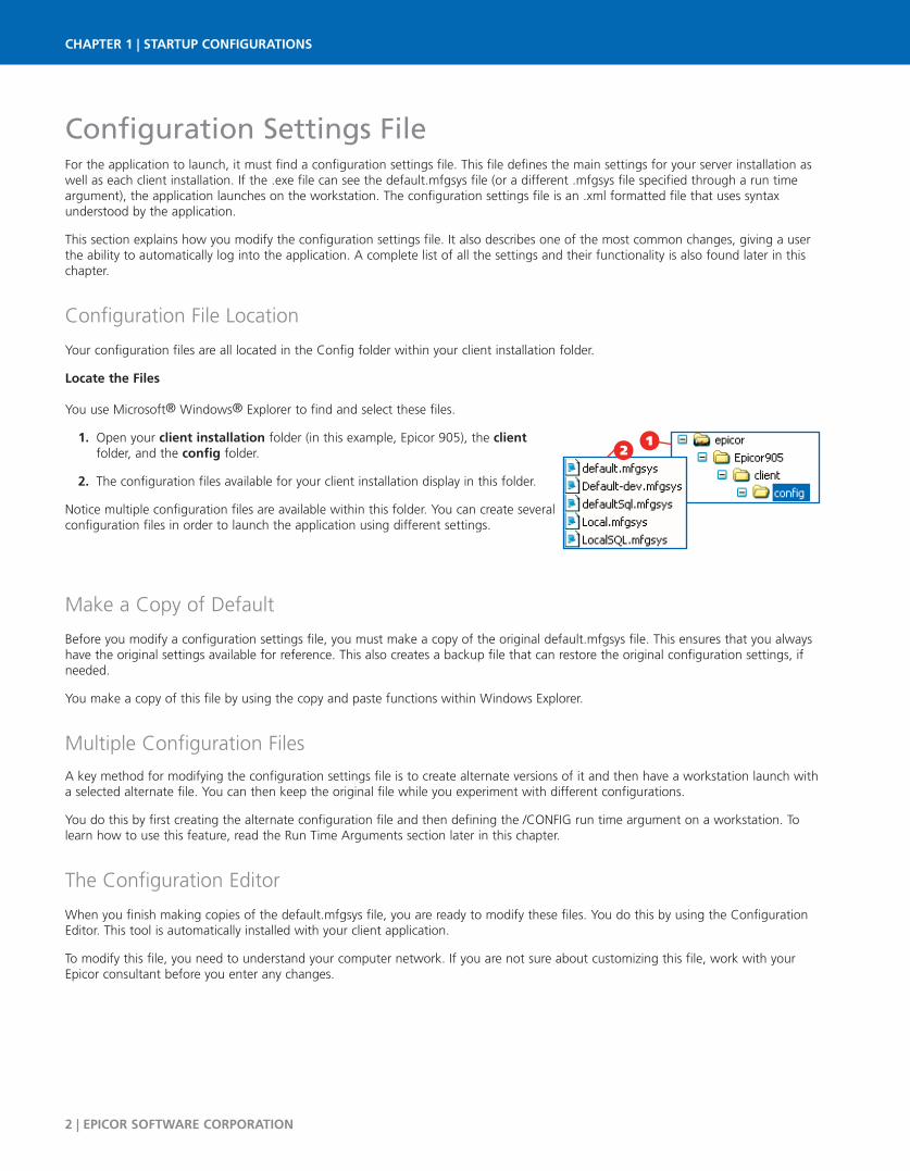
Your configuration files are all located in the Config folder within your client installation folder.
Locate the Files
You use Microsoft® Windows® Explorer to find and select these files.
Open your client installation folder (in this example, Epicor 905), the client1.folder, and the config folder.
The configuration files available for your client installation display in this folder.2.
Notice multiple configuration files are available within this folder. You can create severalconfiguration files in order to launch the application using different settings.
Make a Copy of Default
Before you modify a configuration settings file, you must make a copy of the original default.mfgsys file. This ensures that you alwayshave the original settings available for reference. This also creates a backup file that can restore the original configuration settings, ifneeded.
You make a copy of this file by using the copy and paste functions within Windows Explorer.
Multiple Configuration Files
A key method for modifying the configuration settings file is to create alternate versions of it and then have a workstation launch witha selected alternate file. You can then keep the original file while you experiment with different configurations.
You do this by first creating the alternate configuration file and then defining the /CONFIG run time argument on a workstation. Tolearn how to use this feature, read the Run Time Arguments section later in this chapter.
The Configuration Editor
When you finish making copies of the default.mfgsys file, you are ready to modify these files. You do this by using the ConfigurationEditor. This tool is automatically installed with your client application.
To modify this file, you need to understand your computer network. If you are not sure about customizing this file, work with yourEpicor consultant before you enter any changes.
12
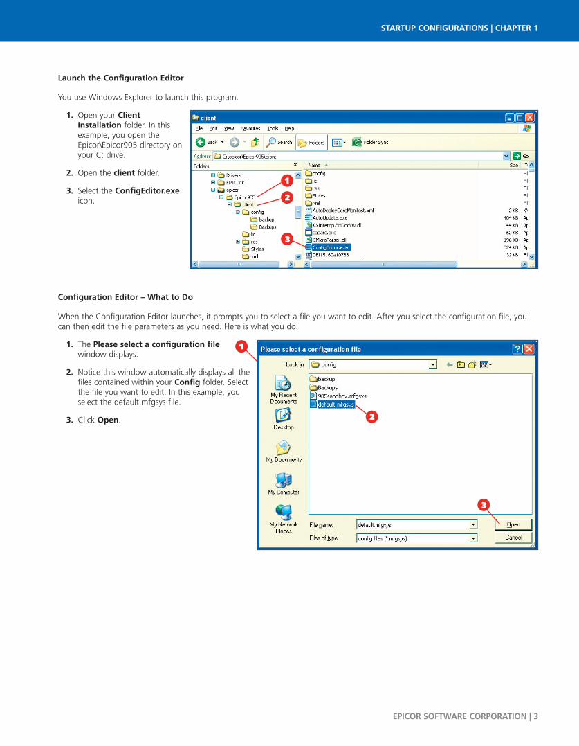
Launch the Configuration Editor
You use Windows Explorer to launch this program.
Open your Client1.Installation folder. In thisexample, you open theEpicor\Epicor905 directory onyour C: drive.
Open the client folder.2.
Select the ConfigEditor.exe3.icon.
Configuration Editor – What to Do
When the Configuration Editor launches, it prompts you to select a file you want to edit. After you select the configuration file, youcan then edit the file parameters as you need. Here is what you do:
The Please select a configuration file1.window displays.
Notice this window automatically displays all the2.files contained within your Config folder. Selectthe file you want to edit. In this example, youselect the default.mfgsys file.
Click Open.3.
EPICOR SOFTWARE CORPORATION | 3
STARTUP CONFIGURATIONS | CHAPTER 1
1
2
3
1
2
3

The Configuration Editor displays.4.
The configuration file settings are divided into5.several sheets. The Application sheet displaysall the settings that apply to the overallapplication. You define settings likeAppServerURL, ResourceFile, and Version here.
The User sheet contains the settings you can6.adjust for the specific user on this clientworkstation.
The Deployment sheet contains the settings for7.moving, or deploying, files from your server tothe client installation.
The Help sheet contains the settings that define8.the directory paths for the application help, on-line support, and the Feature Summary. Usethese options to define where this configurationfile looks for documentation and supportresources.
Use the Sort sheet to define the method used9.globally to sort strings within the application.Your options are stringSort and wordSort. You can also create exceptions to the default sort method on this sheet.
The Tools sheet contains the default settings that are needed to use the Software Developer Kit (SDK). Sold separately from10.the application, this toolset enables developers and advanced users to extend the application to create new tables, businessobjects, and UI forms. If you use the SDK, these default values are automatically added to your configuration file. If you need,however, you can edit them on this sheet.
To change a setting, enter an expected value in its field. An expected value is a parameter that is compatible with the setting.11.For example, you can use the Culture Code to define the default language displayed on the Login window for this clientinstallation. You can enter any ISO language code in this field.
When you have modified all the settings you need, click Save.12.
To exit the Configuration Editor, click Close.13.
The selected configuration file now has your revised settings. The next time theapplication is launched using this configuration file, your new settings become active.
2Example - Automatic Login
A common reason you modify this file is so the user can automatically log into the application. When this user double-clicks theprogram icon on the desktop, both the user name and password populate the Log On window and the application launchesimmediately.
CHAPTER 1 | STARTUP CONFIGURATIONS
4 | EPICOR SOFTWARE CORPORATION
For details on all the settings contained onthese sheets, read the Settings – TheComplete List section later in this chapter.
108
6
4 97
5
1312
11

To set up the automatic login, modify several settings within the default.mfgsys file (or another configuration file).
Launch the Configuration Editor and select the1.default.mfgsys file.
Click Open.2.
The Config file:default.mfgsys window3.displays. Click the User tab.
Enter a UserID. This value is the identifier for the4.user who is logging into the application fromthis workstation. Enter the identifier defined forthis account within User AccountMaintenance. In this example, you enter JaneSmith.
Enter a Password. This value is the password for5.the user who is logging into the application fromthis workstation. Enter the password defined forthis account.
Click Save.6.
Click Close. This configuration file is saved with7.the new settings.
The next time this user clicks the desktop icon, theLog On window does not display. On this clientmachine, the application automatically launches usingthis user account.
STARTUP 6 7
EPICOR SOFTWARE CORPORATION | 5
STARTUP CONFIGURATIONS | CHAPTER 1
1
2
6
4
7
5
3

Settings - The Complete List
This series of tables list all the settings available within the default.mfgsys file. Each setting has its own row; Purpose and ExpectedValues are displayed in the right column. Each section displays its settings in alphabetical order.
New settings may have been added to the configuration file since the publication of this user guide. For the most up-to-dateinformation, review the Configuration Settings File topic within application help.
Application Settings
The Application settings contain general connection settings and configuration settings. You change these settings to apply custom(OEM) style themes to the application. You can also define custom images and text through these settings.
Typically, system administrators define these settings and then distribute the updated configuration files to all workstations within thenetwork for which they apply.
CHAPTER 1 | STARTUP CONFIGURATIONS
6 | EPICOR SOFTWARE CORPORATION
SETTING PURPOSE AND EXPECTED VALUES
AppServerFileTransfer
Defines whether business object logic or File-Copy logic is used to transfer files (attachments, reports,and so on) from the client to the AppServer in a smart client installation. Available values:
BusinessObject – When you specify this option, a standard client to server communication method isused while the application transfers information from the client to the AppServer file system. You thenhave increased security, as the AppServer file system does not need to be accessed by the clientWindows user.
Direct – When you specify this option, the Windows File-Copy logic is used to transfer information fromthe client to the AppServer file system. You need to expose the AppServer file system for Read/Writeaccess by the client Windows user.
AppServerURL
The address of the appserver where the client connects protocol://server:port; it uses the form value“AppServerDC://servername:port”.
Protocol – AppServerDC by default, or else AppServer for load balancing.
Server – Host name of the machine that runs AppServer.
Port – The port of the broker that runs the software. Default is 9001. Also note, the AppServer acceptsstrings and numbers, but the port value only accepts numbers.
AlternateCacheFolder
The location of the local disk cache folder. This folder is used to hold cached .xml files. If none isspecified, the default is: C:\Documents and Settings\All Users\Application Data\Epicor (Windows XP) orC:\ProgramData\Epicor (Windows 7)
This folder accommodates some environment variables which can be substituted during startup.
%UserName% – The Windows ID of the user. Example: jsmith
%UserDomain% – The Windows user domain. Example: USEAST
%AppData% – The application data folder. Example: C:\Documents and Settings\ jsmith\ApplicationData (Windows XP) or C:\Users\jsmith\AppData (Windows 7)
%Homepath% – The home path folder. This location is specified in Local Users and Groups. Example:C:\Documents and Settings\jsmith (Windows XP) or C:\Users\jsmith (Windows 7)
%AllUsersProfile% – The location of the All Users profile. Example: C:\Documents and Settings\AllUsers (Windows XP) or C:\Users\Public (Windows 7)
CultureCode
The ISO language/culture code that defines the specific language and format which displays on the LogOn window. For example, “sch” (Simplified Chinese).
This value only affects the Log On window. After the user enters a user name and password and clickspast this window, the language and culture code settings defined on the user account display within theEpicor application.

EPICOR SOFTWARE CORPORATION | 7
STARTUP CONFIGURATIONS | CHAPTER 1
SETTING PURPOSE AND EXPECTED VALUES
CustomResourceFile
A path name to a resource file that contains custom images. You can add images to this file by usingthe Resource Editor; this utility is available for download from EPICweb. Any images contained withinthis custom file will override images within the base resource file. Typically, the value you enter for thissetting is: “.res\MfgCustomImages.resource”.
DuplicateAttachmentMode
The behavior when a duplicate attachment ID exists. Two values can be used:
Prompt – A new attachment ID must be entered.
AutoDateStamp – A date stamp automatically appends to the record.
EnterpriseSearchURL
The Uniform Resource Identifier address the client uses by default to launch the Enterprise Searchfunctionality. When the Enterprise search is launched, it uses the URL you define in this setting value.
You can, however, override this default URL address within each company record; use the CompanyConfiguration > System > General Settings sheet to enter a different Search URL for the specificcompany.
Likewise, you can override the URL value defined on the company on a specific user record. Launch theUser Account Maintenance > Options sheet and enter the alternate Search URL you want for thecurrent user.
The order of precedence for URL addresses:
1. User record (User Account Maintenance)
2. Company record (Company Configuration)
3. Configuration Settings File
HelpAboutCopyrightText The copyright text for the About dialog box.
HelpAboutCopyrightURL The copyright URL for the About dialog box.
HelpAboutImage The bitmap file for the Help About window.
HelpAboutProductText The product text for the About dialog box.
HelpAboutTitleText The title text for the About dialog box.
HHCustomMenuID The menu ID for the sub process that causes customized Handheld menus to load onto your screen.
MaxBOMRU
The number of most frequently used business objects whose security settings should be cached when auser logs in.
Logic then tracks this number of business objects in the following XML file: C:\Documents andSettings\All Users\Application Data\Epicor\<appserver_and_port>\<version>\<company>\BOSecMRUList\BOMRUList_<userID>.xml (Windows XP) or C:\ProgramData\Epicor\<appserver_and_port>\<version>\<company>\ BOSecMRUList\BOMRUList_<userID>.xml (Windows 7)
This cached information helps minimize the number of calls between client and server, improvingperformance.
This path is the default location of the cache folder, but it can change based on theAlternateCacheFolder setting.
MaxClssAttrMRU
The number of most frequently used datasets. The information on the tracked datasets is used at loginto both fetch (get) and memory cache the extended properties for frequently used datasets.
The logic tracks this number of datasets in the following XML file: C:\Documents and Settings\AllUsers\Application Data\Epicor\<appserver_and_port>\<version>\<company>ClsAttrMRUList\ClsAttrMRUList_<userID>.xml (Windows XP) or C:\ProgramData\Epicor\<appserver_and_port>\<version>\<company>ClsAttrMRUList\ ClsAttrMRUList_<userID>.xml (Windows 7)
This cached information helps minimize the number of calls between client and server, improvingperformance.
This path is the default location of the cache folder, but it can change based on theAlternateCacheFolder setting.
CHAPTER 1 | STARTUP CONFIGURATIONS
8 | EPICOR SOFTWARE CORPORATION
SETTING PURPOSE AND EXPECTED VALUES
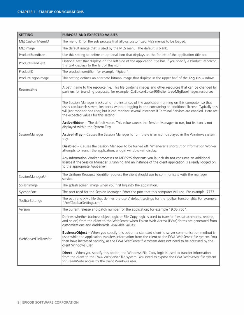
MESCustomMenuID The menu ID for the sub process that allows customized MES menus to be loaded.
MESImage The default image that is used by the MES menu. The default is blank.
ProductBrandIcon Use this setting to define an optional icon that displays on the far left of the application title bar.
ProductBrandTextOptional text that displays on the left side of the application title bar. If you specify a ProductBrandIcon,this text displays to the left of this icon.
ProductID The product identifier; for example "Epicor".
ProductLogonImage This setting defines an alternate bitmap image that displays in the upper half of the Log On window.
ResourceFileA path name to the resource file. This file contains images and other resources that can be changed bypartners for branding purposes; for example: C:\Epicor\Epicor905\client\res\MfgBaseImages.resources
SessionManager
The Session Manager tracks all of the instances of the application running on this computer, so thatusers can launch several instances without logging in and consuming an additional license. Typically thiswill just monitor one user, but it can monitor several instances if Terminal Services are enabled. Here arethe expected values for this setting:
ActiveHidden – The default value. This value causes the Session Manager to run, but its icon is notdisplayed within the System Tray.
ActiveInTray – Causes the Session Manager to run; there is an icon displayed in the Windows systemtray.
Disabled – Causes the Session Manager to be turned off. Whenever a shortcut or Information Workerattempts to launch the application, a login window will display.
Any Information Worker processes or MFGSYS shortcuts you launch do not consume an additionallicense if the Session Manager is running and an instance of the client application is already logged onto the appropriate AppServer.
SessionManagerUriThe Uniform Resource Identifier address the client should use to communicate with the managerservice.
SplashImage The splash screen image when you first log into the application.
SysmonPort The port used for the Session Manager. Enter the port that this computer will use. For example: 7777
ToolbarSettingsThe path and XML file that defines the users’ default settings for the toolbar functionality. For example,“.\res\ToolbarSettings.xml”.
Version The current release and patch number for the application; for example "9.05.700".
WebServerFileTransfer
Defines whether business object logic or File-Copy logic is used to transfer files (attachments, reports,and so on) from the client to the WebServer when Epicor Web Access (EWA) forms are generated fromcustomizations and dashboards. Available values:
BusinessObject – When you specify this option, a standard client to server communication method isused while the application transfers information from the client to the EWA WebServer file system. Youthen have increased security, as the EWA WebServer file system does not need to be accessed by theclient Windows user.
Direct – When you specify this option, the Windows File-Copy logic is used to transfer informationfrom the client to the EWA WebServer file system. You need to expose the EWA WebServer file systemfor Read/Write access by the client Windows user.
User Settings
The User settings contain parameters that only apply to a specific user. Use these parameters to activate the Single Sign On feature,System Monitor settings, login settings, or search settings.
Typically system administrators define these settings for a specific user; this configuration settings file is then used to launch theapplication on the specific workstation.
EPICOR SOFTWARE CORPORATION | 9
STARTUP CONFIGURATIONS | CHAPTER 1
SETTING PURPOSE AND EXPECTED VALUES
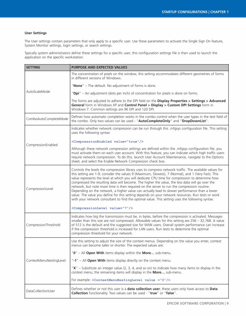
AutoScaleMode
The concentration of pixels on the window, this setting accommodates different geometries of formsin different versions of Windows.
“None” – The default. No adjustment of forms is done.
“Dpi” – An adjustment (dots per inch) of concentration for pixels is done on forms.
The forms are adjusted to adhere to the DPI field on the Display Properties > Settings > AdvancedGeneral form in Windows XP and Control Panel > Display > Custom DPI Settings form inWindows 7. Common settings are 96 DPI and 120 DPI.
ComboAutoCompleteModeDefines how automatic completion works in the combo control when the user types in the text field ofthe combo. Only two values can be used - “AutoCompleteOnly” and “DropDownList”.
CompressionEnabled
Indicates whether network compression can be run through this .mfgsys configuration file. This settinguses the following syntax:
<CompressionEnabled value=”true”/> Although these network compression settings are defined within the .mfgsys configuration file, youmust activate them on each user account. With this feature, you can indicate which high traffic usersrequire network compression. To do this, launch User Account Maintenance, navigate to the Optionssheet, and select the Enable Network Compression check box.
CompressionLevel
Controls the levels the compression library uses to compress network traffic. The available values forthis setting are 1-9; consider the values 9 (Maximum, Slowest), 7 (Normal), and 1 (Very Fast). Thisvalue represents the level at which you will dedicate CPU time for compression to determine howcompressed the resulting data will become. The higher the value, the less data will go over thenetwork, but note more time is then required on the server to run the compression routine.Depending on the network, a higher value can actually lead to slower performance than a lowervalue. The value you define for this setting depends on your network resources. Run tests or workwith your network consultant to find the optimal value. This setting uses the following syntax:
<CompressionLevel value=”7”/>
CompressionThreshold
Indicates how big the transmission must be, in bytes, before the compression is activated. Messagessmaller than this size are not compressed. Allowable values for this setting are 256 – 32,768. A valueof 512 is the default and the suggested size for WAN users. Overall system performance can increaseif the compression threshold is increased for LAN users. Run tests to determine the optimalcompression threshold for your network.
ContextMenuNestingLevel
Use this setting to adjust the size of the context menus. Depending on the value you enter, contextmenus can become taller or shorter. The expected values are:
“0” – All Open With items display within the More… sub-menu.
“-1” – All Open With items display directly on the context menu.
“X” – Substitute an integer value (2, 3, 4, and so on) to indicate how many items to display in thecontext menu; the remaining items will display in the More… sub-menu.
For example: <ContextMenuNestingLevel value =”0”/>
DataCollectionUserDefines whether or not this user is a data collection user; these users only have access to DataCollection functionality. Two values can be used - “true” or “false”.

CHAPTER 1 | STARTUP CONFIGURATIONS
10 | EPICOR SOFTWARE CORPORATION
SETTING PURPOSE AND EXPECTED VALUES
DefaultSearchFormLocation
This value controls the default location of search forms as they open. Available options:
Top – Search forms open at the top of the window from where you launched the search. This valuegenerally provides more real estate for displaying the search results.
Center – Search forms open in the middle of the window from where you launched the Search. Thissetting is best for Multi-Monitor configured client systems, as the search window opens cen tered onthe user interface form regardless of which monitor is displaying the Epicor application.
DefaultSearchPageSizeUse this value to control the maximum number of records returned by a search for display within thesearch results. Lower values generally make more efficient use of server and network resources.Common settings range from 100 to 1000.
FormOpenMode
Use this setting to determine the initial behavior of a user interface (UI) form as it opens. When novalue is specified for this setting, a UI form opens with no special processing. Available options:
AutoSearch – The primary search for each UI form automatically displays as the form launches.
AutoPopulate – The primary search for each UI form is automatically run, and all selected recordsautomatically populate the form as it displays on your screen.
LastLoginID
This setting is used with the LoginDefault setting.
When LoginDefault is set to Last, the value of LastLoginID is the last user ID entered during the logonprocess.
When LoginDefault is set to List, the value of LastLoginID is a series of previously entered user IDsthat have accessed the application.
For the other LoginDefault setting values, LastLoginID is not used and is typically set to have no value.
LoginDefault
The login default setting that defines what displays in the User Name field. Possible values:
“Last” – Displays the last user ID that was used.
“List” – Displays a list of all the recently entered user identifiers.
“Windows” – Displays the same user ID used to log onto Windows on this client machine.
“None” – No default value; the User Name field will be blank.
Password The password for auto-login; for example, “BobS”.
RibbonView
This setting controls if a ribbon view or a standard toolbar is used on forms. Possible values:
“True” – The commands from the standard toolbar will be dispersed in several ribbon tabs on thetop of forms.
“False” – A standard toolbar will display on forms.
SelectTextOnEnterThis setting determines whether an entire word or number is selected when you click a field with avalue. Only two expected values can be used - “true” or “false”.
SingleSignOnThe choices are true or false (the default). A value of true means the application should use singlesign-on logic, and not prompt for user ID and password but instead use the user ID of the currentWindows user.
SmtpServer The location of the smtp server; the smtp server is required for email.
StartSystemMonitorDefines whether or not the System Monitor will start when the application is launched. Only two
values can be used - “true” or “false”.
EPICOR SOFTWARE CORPORATION | 11
STARTUP CONFIGURATIONS | CHAPTER 1
SETTING PURPOSE AND EXPECTED VALUES
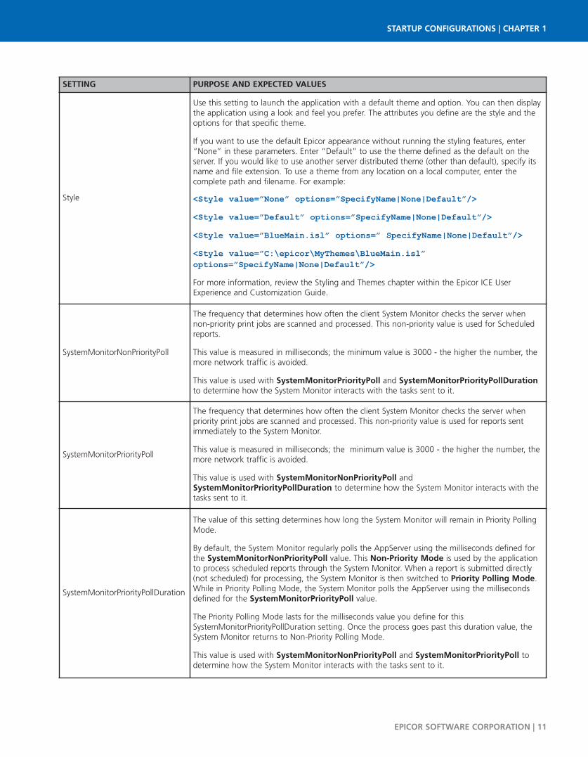
Style
Use this setting to launch the application with a default theme and option. You can then displaythe application using a look and feel you prefer. The attributes you define are the style and theoptions for that specific theme.
If you want to use the default Epicor appearance without running the styling features, enter“None” in these parameters. Enter “Default” to use the theme defined as the default on theserver. If you would like to use another server distributed theme (other than default), specify itsname and file extension. To use a theme from any location on a local computer, enter thecomplete path and filename. For example:
<Style value=”None” options=”SpecifyName|None|Default”/><Style value=”Default” options=”SpecifyName|None|Default”/><Style value=”BlueMain.isl” options=” SpecifyName|None|Default”/><Style value=”C:\epicor\MyThemes\BlueMain.isl”options=”SpecifyName|None|Default”/>For more information, review the Styling and Themes chapter within the Epicor ICE UserExperience and Customization Guide.
SystemMonitorNonPriorityPoll
The frequency that determines how often the client System Monitor checks the server whennon-priority print jobs are scanned and processed. This non-priority value is used for Scheduledreports.
This value is measured in milliseconds; the minimum value is 3000 - the higher the number, themore network traffic is avoided.
This value is used with SystemMonitorPriorityPoll and SystemMonitorPriorityPollDurationto determine how the System Monitor interacts with the tasks sent to it.
SystemMonitorPriorityPoll
The frequency that determines how often the client System Monitor checks the server whenpriority print jobs are scanned and processed. This non-priority value is used for reports sentimmediately to the System Monitor.
This value is measured in milliseconds; the minimum value is 3000 - the higher the number, themore network traffic is avoided.
This value is used with SystemMonitorNonPriorityPoll andSystemMonitorPriorityPollDuration to determine how the System Monitor interacts with thetasks sent to it.
SystemMonitorPriorityPollDuration
The value of this setting determines how long the System Monitor will remain in Priority PollingMode.
By default, the System Monitor regularly polls the AppServer using the milliseconds defined forthe SystemMonitorNonPriorityPoll value. This Non-Priority Mode is used by the applicationto process scheduled reports through the System Monitor. When a report is submitted directly(not scheduled) for processing, the System Monitor is then switched to Priority Polling Mode.While in Priority Polling Mode, the System Monitor polls the AppServer using the millisecondsdefined for the SystemMonitorPriorityPoll value.
The Priority Polling Mode lasts for the milliseconds value you define for thisSystemMonitorPriorityPollDuration setting. Once the process goes past this duration value, theSystem Monitor returns to Non-Priority Polling Mode.
This value is used with SystemMonitorNonPriorityPoll and SystemMonitorPriorityPoll todetermine how the System Monitor interacts with the tasks sent to it.
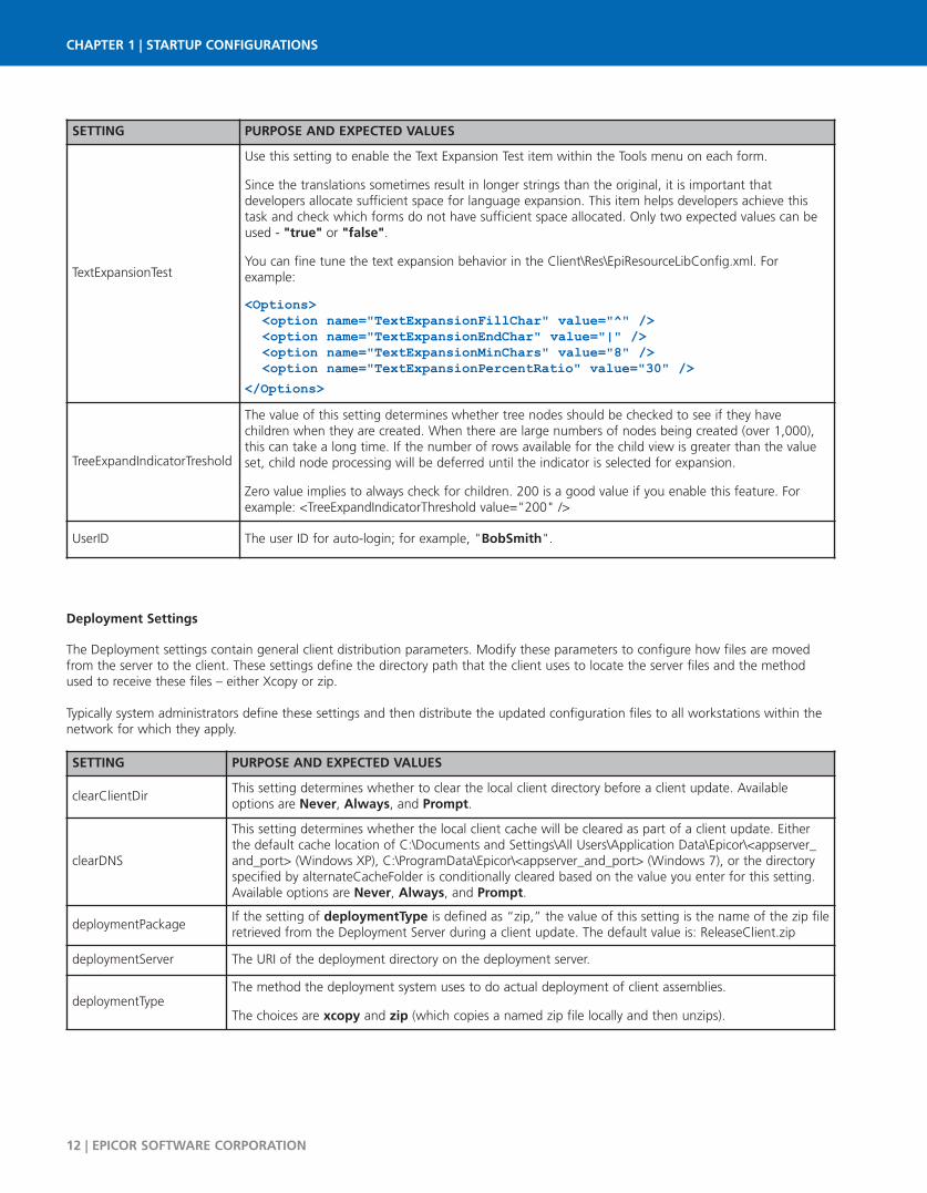
Deployment Settings
The Deployment settings contain general client distribution parameters. Modify these parameters to configure how files are movedfrom the server to the client. These settings define the directory path that the client uses to locate the server files and the methodused to receive these files – either Xcopy or zip.
Typically system administrators define these settings and then distribute the updated configuration files to all workstations within thenetwork for which they apply.
CHAPTER 1 | STARTUP CONFIGURATIONS
12 | EPICOR SOFTWARE CORPORATION
SETTING PURPOSE AND EXPECTED VALUES
clearClientDirThis setting determines whether to clear the local client directory before a client update. Availableoptions are Never, Always, and Prompt.
clearDNS
This setting determines whether the local client cache will be cleared as part of a client update. Eitherthe default cache location of C:\Documents and Settings\All Users\Application Data\Epicor\<appserver_and_port> (Windows XP), C:\ProgramData\Epicor\<appserver_and_port> (Windows 7), or the directoryspecified by alternateCacheFolder is conditionally cleared based on the value you enter for this setting.Available options are Never, Always, and Prompt.
deploymentPackageIf the setting of deploymentType is defined as “zip,” the value of this setting is the name of the zip fileretrieved from the Deployment Server during a client update. The default value is: ReleaseClient.zip
deploymentServer The URI of the deployment directory on the deployment server.
deploymentTypeThe method the deployment system uses to do actual deployment of client assemblies.
The choices are xcopy and zip (which copies a named zip file locally and then unzips).
SETTING PURPOSE AND EXPECTED VALUES
TextExpansionTest
Use this setting to enable the Text Expansion Test item within the Tools menu on each form.
Since the translations sometimes result in longer strings than the original, it is important thatdevelopers allocate sufficient space for language expansion. This item helps developers achieve thistask and check which forms do not have sufficient space allocated. Only two expected values can beused - "true" or "false".
You can fine tune the text expansion behavior in the Client\Res\EpiResourceLibConfig.xml. Forexample:
<Options><option name="TextExpansionFillChar" value="^" /><option name="TextExpansionEndChar" value="|" /><option name="TextExpansionMinChars" value="8" /><option name="TextExpansionPercentRatio" value="30" />
</Options>
TreeExpandIndicatorTreshold
The value of this setting determines whether tree nodes should be checked to see if they havechildren when they are created. When there are large numbers of nodes being created (over 1,000),this can take a long time. If the number of rows available for the child view is greater than the valueset, child node processing will be deferred until the indicator is selected for expansion.
Zero value implies to always check for children. 200 is a good value if you enable this feature. Forexample: <TreeExpandIndicatorThreshold value="200" />
UserID The user ID for auto-login; for example, "BobSmith".
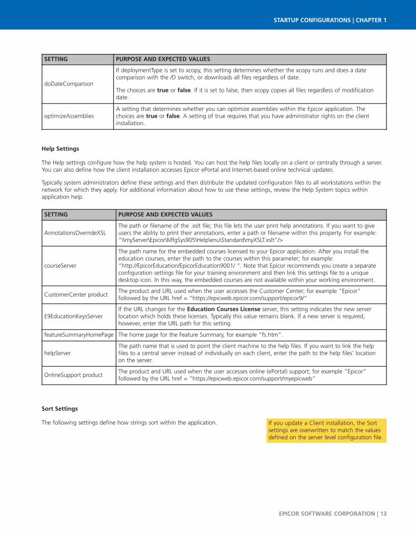
Help Settings
The Help settings configure how the help system is hosted. You can host the help files locally on a client or centrally through a server.You can also define how the client installation accesses Epicor ePortal and Internet-based online technical updates.
Typically system administrators define these settings and then distribute the updated configuration files to all workstations within thenetwork for which they apply. For additional information about how to use these settings, review the Help System topics withinapplication help.
Sort Settings
The following settings define how strings sort within the application.
EPICOR SOFTWARE CORPORATION | 13
STARTUP CONFIGURATIONS | CHAPTER 1
SETTING PURPOSE AND EXPECTED VALUES
AnnotationsOverrideXSLThe path or filename of the .xslt file; this file lets the user print help annotations. If you want to giveusers the ability to print their annotations, enter a path or filename within this property. For example:“\\myServer\Epicor\MfgSys905\Help\enu\Standard\myXSLT.xslt”/>
courseServer
The path name for the embedded courses licensed to your Epicor application. After you install theeducation courses, enter the path to the courses within this parameter; for example:“http://EpicorEducation/EpicorEducation9001/ “. Note that Epicor recommends you create a separateconfiguration settings file for your training environment and then link this settings file to a uniquedesktop icon. In this way, the embedded courses are not available within your working environment.
CustomerCenter productThe product and URL used when the user accesses the Customer Center; for example “Epicor”followed by the URL href = “https://epicweb.epicor.com/support/epicor9/”
E9EducationKeysServerIf the URL changes for the Education Courses License server, this setting indicates the new serverlocation which holds these licenses. Typically this value remains blank. If a new server is required,however, enter the URL path for this setting.
featureSummaryHomePage The home page for the Feature Summary, for example “fs.htm”.
helpServerThe path name that is used to point the client machine to the help files. If you want to link the helpfiles to a central server instead of individually on each client, enter the path to the help files’ locationon the server.
OnlineSupport productThe product and URL used when the user accesses online (ePortal) support; for example “Epicor”followed by the URL href = “https://epicweb.epicor.com/support/myepicweb”
SETTING PURPOSE AND EXPECTED VALUES
doDateComparison
If deploymentType is set to xcopy, this setting determines whether the xcopy runs and does a datecomparison with the /D switch, or downloads all files regardless of date.
The choices are true or false. If it is set to false, then xcopy copies all files regardless of modificationdate.
optimizeAssembliesA setting that determines whether you can optimize assemblies within the Epicor application. Thechoices are true or false. A setting of true requires that you have administrator rights on the clientinstallation.
If you update a Client installation, the Sortsettings are overwritten to match the valuesdefined on the server level configuration file.
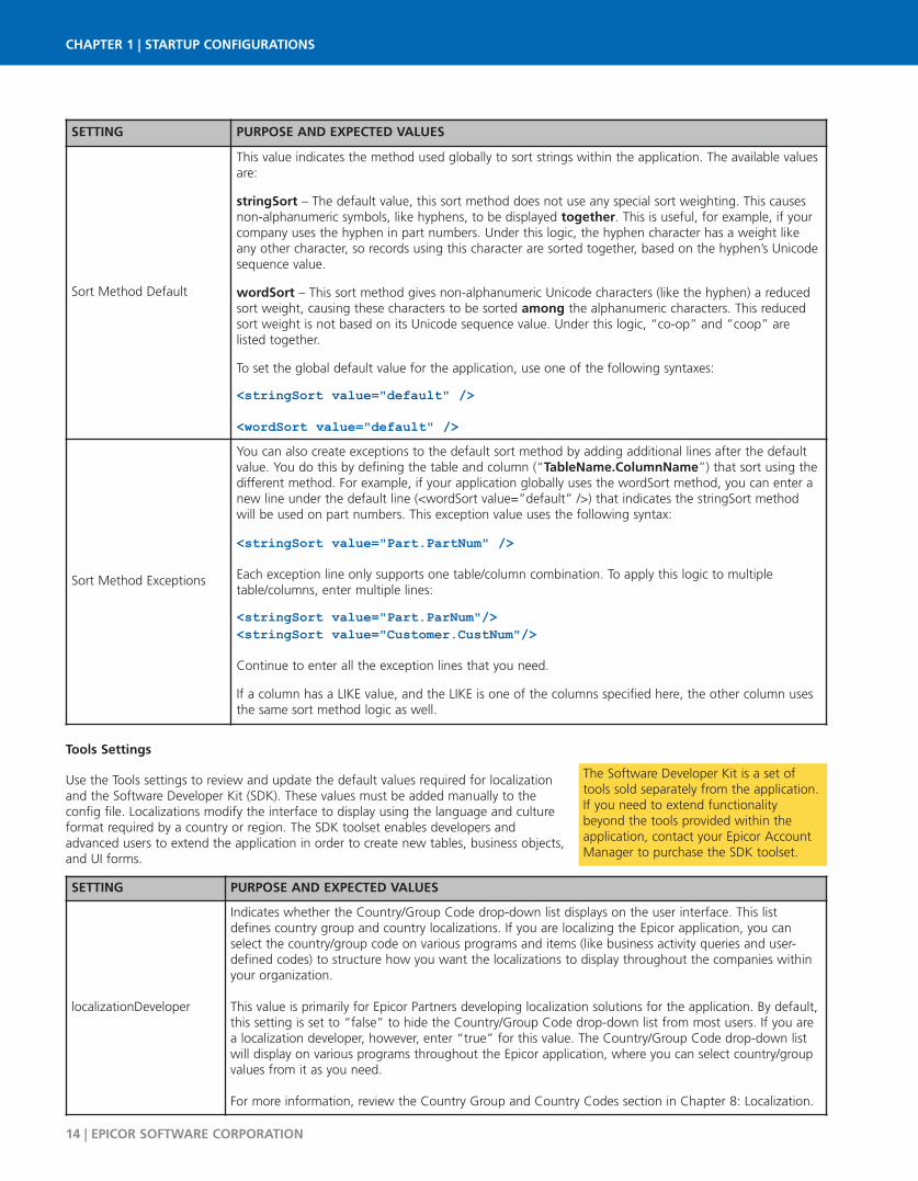
Tools Settings
Use the Tools settings to review and update the default values required for localizationand the Software Developer Kit (SDK). These values must be added manually to theconfig file. Localizations modify the interface to display using the language and cultureformat required by a country or region. The SDK toolset enables developers andadvanced users to extend the application in order to create new tables, business objects,and UI forms.
CHAPTER 1 | STARTUP CONFIGURATIONS
14 | EPICOR SOFTWARE CORPORATION
The Software Developer Kit is a set oftools sold separately from the application.If you need to extend functionalitybeyond the tools provided within theapplication, contact your Epicor AccountManager to purchase the SDK toolset.
SETTING PURPOSE AND EXPECTED VALUES
Sort Method Default
This value indicates the method used globally to sort strings within the application. The available valuesare:
stringSort – The default value, this sort method does not use any special sort weighting. This causesnon-alphanumeric symbols, like hyphens, to be displayed together. This is useful, for example, if yourcompany uses the hyphen in part numbers. Under this logic, the hyphen character has a weight likeany other character, so records using this character are sorted together, based on the hyphen’s Unicodesequence value.
wordSort – This sort method gives non-alphanumeric Unicode characters (like the hyphen) a reducedsort weight, causing these characters to be sorted among the alphanumeric characters. This reducedsort weight is not based on its Unicode sequence value. Under this logic, “co-op” and “coop” arelisted together.
To set the global default value for the application, use one of the following syntaxes:
<stringSort value="default" /><wordSort value="default" />
Sort Method Exceptions
You can also create exceptions to the default sort method by adding additional lines after the defaultvalue. You do this by defining the table and column (“TableName.ColumnName”) that sort using thedifferent method. For example, if your application globally uses the wordSort method, you can enter anew line under the default line (<wordSort value=”default” />) that indicates the stringSort methodwill be used on part numbers. This exception value uses the following syntax:
<stringSort value="Part.PartNum" />Each exception line only supports one table/column combination. To apply this logic to multipletable/columns, enter multiple lines:
<stringSort value="Part.ParNum"/><stringSort value="Customer.CustNum"/>Continue to enter all the exception lines that you need.
If a column has a LIKE value, and the LIKE is one of the columns specified here, the other column usesthe same sort method logic as well.
SETTING PURPOSE AND EXPECTED VALUES
localizationDeveloper
Indicates whether the Country/Group Code drop-down list displays on the user interface. This listdefines country group and country localizations. If you are localizing the Epicor application, you canselect the country/group code on various programs and items (like business activity queries and user-defined codes) to structure how you want the localizations to display throughout the companies within your organization.
This value is primarily for Epicor Partners developing localization solutions for the application. By default,this setting is set to “false” to hide the Country/Group Code drop-down list from most users. If you area localization developer, however, enter “true” for this value. The Country/Group Code drop-down listwill display on various programs throughout the Epicor application, where you can select country/groupvalues from it as you need.
For more information, review the Country Group and Country Codes section in Chapter 8: Localization.

Run Time ArgumentsEach workstation can be set up to launch the application in a specific mode. These modes, or run time arguments, activateimmediately when a user double-clicks on the program icon.
Several run time arguments are available. You can, for example, indicate the application launches either the Dashboard or the MESinterface - instead of the default Main Menu. You can also have the application launch using a different configuration file.
Run time arguments are also useful, for example, when you are customizing programs. Normally during Run Time, you have severalfavorites groups that autoload their programs into memory. You cannot, however, customize autoloaded programs. To disable thisfeature while you are customizing, you use the /AUTOLOADSUPPRESS run time argument; this prevents the application fromautoloading any programs.
You can also use multiple run time arguments at the same time to further define how the application launches on the workstation. Forexample, you want a workstation to only use the MES interface and you also want it to update to the latest version. Because of this,you use both the /MES and /UPDATE run time arguments.
Activate Run Time Arguments
You add run time arguments to the properties of the application icon. Here’s what you do:
On the desktop for the workstation, right-click the application’s icon.1.
A Context Menu displays. Select the Properties command.2.
EPICOR SOFTWARE CORPORATION | 15
STARTUP CONFIGURATIONS | CHAPTER 1
SETTING PURPOSE AND EXPECTED VALUES
OpenEdgeParameters
The files used to link your SDK project to the code for the server (.ini) and your database (pf). The .inifile links the SDK project to the server source code. The .pf file links the SDK project to your database.
For example: -pf C:/_Projects/MfgSys803/Deployment/Server/Config/MfgSys.pf -ininame andC:/_Projects/MfgSys803/Deployment/Server/Config/MfgSys.ini
Password
The password that you use to log into the application. For example: W325
If you do not enter a Password and then attempt to generate SDK business objects, an error messagedisplays that stops this process.
TargetLocationThe client directory that contains your new and customized SDK applications. For example:C:\_Projects\MfgSys905\Source\Client\
TargetNameSpaceThe name that is used to link your SDK projects to their .xsd files. When the .xsd file is created, this target name value is automatically added as an attribute to the .xsd file. For example:www.epicor.com/Mfg/100
UserID
The user identifier that you use to log into the application. For example: ChrisK
If you do not enter a User ID and then attempt to generate SDK business objects, an error messagedisplays that stops this process.
1
2

The application’s Properties window appears, displaying3.the Shortcut tab.
In the Target field, enter a [Space] after the target4.directory path.
Enter a right slash ( / ) or en dash ( - ), followed by the5.run time argument. For example,C:\epicor\905client\client\MfgSys.exe /UPDATE orC:\epicor\905client\client\MfgSys.exe -UPDATE
To add another run time argument, repeat the steps. For6.example: C:\epicor\905client\client\MfgSys.exe /UPDATE/CONFIG=mydefault.mfgsys orC:\epicor\905client\client\MfgSys.exe -UPDATE -CONFIG=mydefault.mfgsys
Click Apply.7.
Click OK.8.
The next time the application is launched on this workstation,it uses the run time argument or arguments you entered.
Run Time Arguments List
This table lists all the run time arguments available for the application. They display in alphabetical order.
You can enter these arguments in two ways. You can enter the entire argument; for example,/AUTOLOADSUPPRESS. The application also accepts, however, a shorthand version that only usesthe first three characters of the argument; for example, AUT.
You can use either the right slash ( / ) or the en dash ( - ) to activate run time arguments.
CHAPTER 1 | STARTUP CONFIGURATIONS
16 | EPICOR SOFTWARE CORPORATION
ARGUMENT PURPOSE
? or HELPThis mode causes a window to appear that displays all the available run time arguments. Use this modeto get a quick list of the current options.
AUTOLOADSUPPRESS
The autoloading feature causes selected favorite groups to load all their programs into memory; itimproves the performance of these programs. If you customize the application, however, you need tosuppress autoloading. By running this argument, you disable autoloading on this workstation.
To learn more about the autoload feature, read the AutoLoad Favorite Groups section in thePersonalization chapter within the Epicor ICE User Experience and Customization Guide.
BASEUse this argument to prevent the loading of any verticalizations (industry-specific user interfacefeatures), customizations, or personalizations. This option is useful for testing the user interface.
New run time arguments may havebeen added since the publicationof this user guide. Use the /HELPor -HELP run time argument todisplay the current list.
8
64
7
5
3
EPICOR SOFTWARE CORPORATION | 17
STARTUP CONFIGURATIONS | CHAPTER 1
ARGUMENT PURPOSE
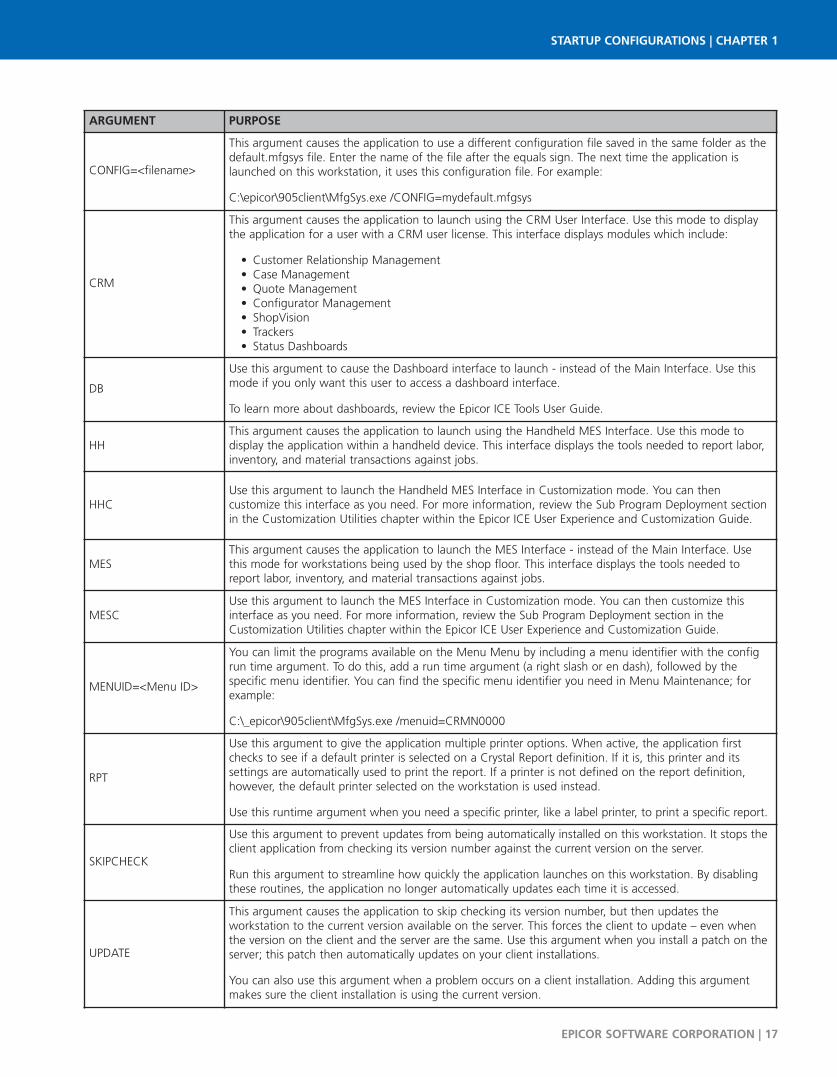
CONFIG=<filename>
This argument causes the application to use a different configuration file saved in the same folder as thedefault.mfgsys file. Enter the name of the file after the equals sign. The next time the application islaunched on this workstation, it uses this configuration file. For example:
C:\epicor\905client\MfgSys.exe /CONFIG=mydefault.mfgsys
CRM
This argument causes the application to launch using the CRM User Interface. Use this mode to displaythe application for a user with a CRM user license. This interface displays modules which include:
Customer Relationship Management •Case Management •Quote Management •Configurator Management •ShopVision •Trackers •Status Dashboards •
DB
Use this argument to cause the Dashboard interface to launch - instead of the Main Interface. Use thismode if you only want this user to access a dashboard interface.
To learn more about dashboards, review the Epicor ICE Tools User Guide.
HHThis argument causes the application to launch using the Handheld MES Interface. Use this mode todisplay the application within a handheld device. This interface displays the tools needed to report labor,inventory, and material transactions against jobs.
HHCUse this argument to launch the Handheld MES Interface in Customization mode. You can thencustomize this interface as you need. For more information, review the Sub Program Deployment sectionin the Customization Utilities chapter within the Epicor ICE User Experience and Customization Guide.
MESThis argument causes the application to launch the MES Interface - instead of the Main Interface. Usethis mode for workstations being used by the shop floor. This interface displays the tools needed toreport labor, inventory, and material transactions against jobs.
MESCUse this argument to launch the MES Interface in Customization mode. You can then customize thisinterface as you need. For more information, review the Sub Program Deployment section in theCustomization Utilities chapter within the Epicor ICE User Experience and Customization Guide.
MENUID=<Menu ID>
You can limit the programs available on the Menu Menu by including a menu identifier with the configrun time argument. To do this, add a run time argument (a right slash or en dash), followed by thespecific menu identifier. You can find the specific menu identifier you need in Menu Maintenance; forexample:
C:\_epicor\905client\MfgSys.exe /menuid=CRMN0000
RPT
Use this argument to give the application multiple printer options. When active, the application firstchecks to see if a default printer is selected on a Crystal Report definition. If it is, this printer and itssettings are automatically used to print the report. If a printer is not defined on the report definition,however, the default printer selected on the workstation is used instead.
Use this runtime argument when you need a specific printer, like a label printer, to print a specific report.
SKIPCHECK
Use this argument to prevent updates from being automatically installed on this workstation. It stops theclient application from checking its version number against the current version on the server.
Run this argument to streamline how quickly the application launches on this workstation. By disablingthese routines, the application no longer automatically updates each time it is accessed.
UPDATE
This argument causes the application to skip checking its version number, but then updates theworkstation to the current version available on the server. This forces the client to update – even whenthe version on the client and the server are the same. Use this argument when you install a patch on theserver; this patch then automatically updates on your client installations.
You can also use this argument when a problem occurs on a client installation. Adding this argumentmakes sure the client installation is using the current version.

CHAPTER 1 | STARTUP CONFIGURATIONS
18 | EPICOR SOFTWARE CORPORATION

STYLING AND THEMES | CHAPTER 2
EPICOR SOFTWARE CORPORATION | 19
Chapter 2Styling and Themes
Complete control over the look and feel of the entire interface is available through the styling functionality. You can use thistoolset to display a pre-built design, or theme, from the options installed with the application. You can also use these tools toedit an existing theme and create a new theme.
Through the styling functionality, you manipulate the look of each item, or component, within the interface – buttons, checkboxes, fields, borders, and other items. You have complete control over the look of each component, as you can update thedifferent states in which they display. For example, you can create multiple button states – normal, selected, pressed – in agraphics program and then add these various states as the default look for all buttons within the application. Because youare updating one user interface definition, or UI role, the changes you make display globally throughout the interface.
Your updated or new theme can then be made available to everyone within your entire organization. This toolset containsexport and import functions, which you can then pass along your revised or new theme to whomever you want.
Use the styling functionality to create a user interface unique for your company, departments, and users. By refining the lookof existing themes or creating new ones, you can transform the application to display an entirely different look and feel.
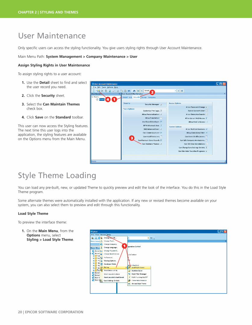
User MaintenanceOnly specific users can access the styling functionality. You give users styling rights through User Account Maintenance.
Main Menu Path: System Management > Company Maintenance > User
Assign Styling Rights in User Maintenance
To assign styling rights to a user account:
1. Use the Detail sheet to find and select the user record you need.
2. Click the Security sheet.
3. Select the Can Maintain Themes check box.
4. Click Save on the Standard toolbar.
This user can now access the Styling features.The next time this user logs into the application, the styling features are availableon the Options menu from the Main Menu.
Style Theme LoadingYou can load any pre-built, new, or updated Theme to quickly preview and edit the look of the interface. You do this in the Load StyleTheme program.
Some alternate themes were automatically installed with the application. If any new or revised themes become available on your system, you can also select them to preview and edit through this functionality.
Load Style Theme
To preview the interface theme:
1. On the Main Menu, from the Options menu, select Styling > Load Style Theme.
| STYLING AND THEMES3 4
CHAPTER 2 | STYLING AND THEMES
20 | EPICOR SOFTWARE CORPORATION
14
2
3
1

2. The Open window displays.
3. This window defaults to the Styles folder. This folder contains all default themes available for your application.
4. Select the theme you want to use. Notice that all themes use the .isl file extension. In this example, you select the ArcticBlue.isl theme.
5. Click Open.
6. The interface now displays using the selected theme.
You can now use this theme for therest of the current session. You canalso use the Runtime Stylist to editthe theme. Note that if you exit theapplication, however, the themereverts back to the default theme.
If you want a different theme tobecome the default, run the ThemeMaintenance program. Use this toolto indicate that a different, selectedtheme becomes the default lookwhen you launch this client application. For more informationabout this tool, read the ThemeMaintenance section later in this chapter.
5
STYLING AND THEMES | CHAPTER 2
EPICOR SOFTWARE CORPORATION | 21
Epicor recommends youto save all your themeswithin this folder; thismakes it easy for yourusers to find and selectthem. This folder is located within the C:\epicor\<ClientInstallationName>\Client\Styles.
Another way to define a default theme is to change a settingwithin the Configuration Settings File.This file controls severalglobal sessions for your client installation. To define a defaulttheme in this file, you change the Styles setting. You can learnmore by reviewing the Configuration Settings File section withinChapter 1: Startup Configurations. Customized controls can alsobe set up to display a specific style; review this functionalitywithin Chapter 5: Advanced Customization.
5
3
6
4
2

Runtime StylistThe primary tool of the Styling functionality is the Runtime Stylist. Use this tool to change the appearance of every component withinthe user interface. You can then see this change immediately, as the interface is updated while the application runs. This helps youdecide if you like, or do not like, the change to the interface.
You use this tool to modify an existing theme or create an entirely new theme. You can then use this theme for your client installationand make it available to other users within your company.
The application runs in two modes – Run Mode (or Runtime) and Developer Mode. Typically you use the application in Run Mode,which means that the application sheets are used for normal activities like data entry and processing. The Runtime Stylist operates inRun Mode, so you can see the application in action while you edit the styling.
In Developer Mode you suspend the normal operation of the program in order to customize it. The styling features are never used inDeveloper Mode. For more information about the two modes, read Chapter 4: Basic Customization.
Runtime Stylist divides the user interface items into three main categories – UI Roles, Component Role Settings, and Shared Object Role Settings.
Each of these categories has various properties and options that you can manipulate as you need. The differences between these categories are explored later in this section.
Launch the Runtime Stylist
To launch the Runtime Stylist:
1. On the Main Menu, from the Options menu, select Styling > Runtime Styler.
CHAPTER 2 | STYLING AND THEMES
22 | EPICOR SOFTWARE CORPORATION
The Runtime Stylist is a third party applicationpublished by Infragistics, Inc.® The tool is based onthis company’s NetAdvantage® AppStylist®
application. This section of the chapter gives you atour of the primary features of this tool.Forcomplete information on this company and itsproducts, please visit their website at:www.infragistics.com.
1

2. The Runtime Stylist displays next to the Main Menu.
You can now use this program to update or create new themes.
Runtime Stylist – Primary Controls
This section defines all the main controls within the Runtime Stylist. Use these controls to create a new theme, load an existing theme,and manage the default styling on specific components.
Use Style Library
The Style Library displays on the top section of the Runtime Stylist. This section contains the primary controls for this program.Available options:
1. The Style Library: section indicates which theme is currently loaded. In this example, the Office2007Calibri.isl theme displays. Note that the files for themes all use the .isl extension.
2. Click the New button to create a new theme.
3. To update an existing theme, click the Load button.
4. To create a copy of the current theme, click the Save As… button.
5. Click Save to record your changes to a current theme.
6. If you want to constantly display the Property Panel, click the Show/Hide Property Panel button. The Property Panel always stays on your screen; it displays different items based on the selected setting, component, or UI role.
7. The Update Mode tab defines how the interface refreshes after you make changes to the current theme. The Runtime Stylist is set to immediately update the interface; you cannot change this value.
STYLING AND THEMES | CHAPTER 2
EPICOR SOFTWARE CORPORATION | 23
2
7 32
6
45
1
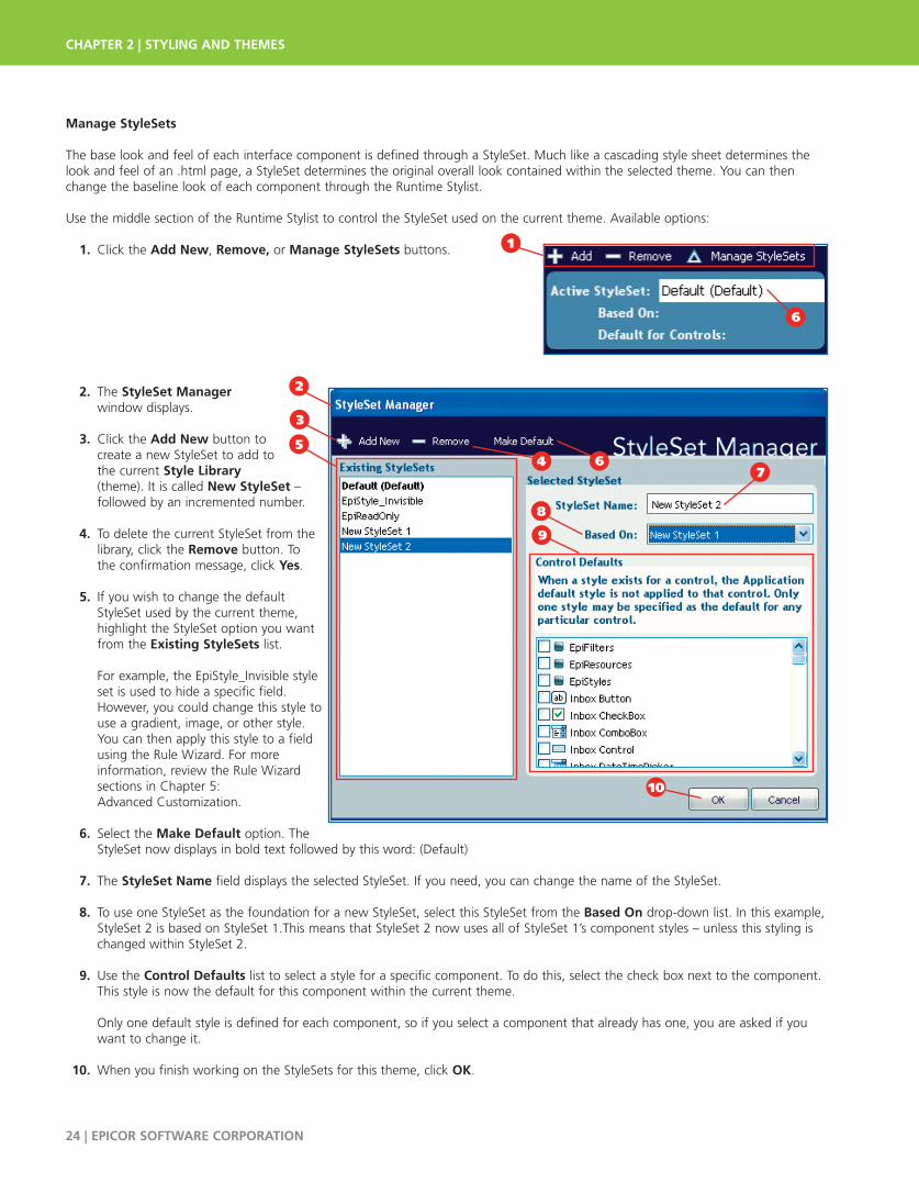
Manage StyleSets
The base look and feel of each interface component is defined through a StyleSet. Much like a cascading style sheet determines thelook and feel of an .html page, a StyleSet determines the original overall look contained within the selected theme. You can thenchange the baseline look of each component through the Runtime Stylist.
Use the middle section of the Runtime Stylist to control the StyleSet used on the current theme. Available options:
1. Click the Add New, Remove, or Manage StyleSets buttons.
2. The StyleSet Manager window displays.
3. Click the Add New button to create a new StyleSet to add to the current Style Library (theme). It is called New StyleSet – followed by an incremented number.
4. To delete the current StyleSet from the library, click the Remove button. To the confirmation message, click Yes.
5. If you wish to change the default StyleSet used by the current theme, highlight the StyleSet option you want from the Existing StyleSets list.
For example, the EpiStyle_Invisible style set is used to hide a specific field. However, you could change this style to use a gradient, image, or other style. You can then apply this style to a field using the Rule Wizard. For more information, review the Rule Wizard sections in Chapter 5: Advanced Customization.
6. Select the Make Default option. The StyleSet now displays in bold text followed by this word: (Default)
7. The StyleSet Name field displays the selected StyleSet. If you need, you can change the name of the StyleSet.
8. To use one StyleSet as the foundation for a new StyleSet, select this StyleSet from the Based On drop-down list. In this example, StyleSet 2 is based on StyleSet 1.This means that StyleSet 2 now uses all of StyleSet 1’s component styles – unless this styling is changed within StyleSet 2.
9. Use the Control Defaults list to select a style for a specific component. To do this, select the check box next to the component. This style is now the default for this component within the current theme.
Only one default style is defined for each component, so if you select a component that already has one, you are asked if you want to change it.
10. When you finish working on the StyleSets for this theme, click OK.
CHAPTER 2 | STYLING AND THEMES
24 | EPICOR SOFTWARE CORPORATION
1
8
4
9
7
2
10
6
3
56

Resources
Resources are containers of style information that you can then use within themes. A resource can be any item you create or add to a theme, like a gradient or a graphic file. Each resource can then be applied to a UI Role.
You can use the Runtime Styler to import and export various resources (graphics, colors, and other settings) that you use with yourthemes. You can then incorporate these resources into any role on the user interface that you need.
UI Roles are styling records that create a uniform look for the various interface components like buttons, fields, borders, check boxes,and other items. To learn more about UI Roles, read the UI Roles section later in this chapter.
Manage Resources
Use the Resources tab to manage all the resources stored within the current Style Library (theme). To use this tab:
1. Click the Resources tab.
2. Click the Add New button to create a new resource. This displays the Properties Panel; use this window to create the resource. To learn more about this key styling window, read the UI Roles section later in this chapter.
3. After you add a resource to the current Style Library, it is labeled as Resource 1, Resource 2 and so on. To change the label text, right-click the resource; its context menu displays. Select the Rename command to change the label.
4. Notice that you also Add New and Remove resources through this context menu.
5. If you want to duplicate the selected resource, select the Create Copy command from the context menu.
6. To create a new resource from another resource, use the commands under the Copy From submenu.
7. To delete a resource from the Style Library, highlight it and click the Remove button.
8. You can also pull in the resources from another style library (theme). To do this, click the Import button. This launches the OpenStyle Library window from which you select an .isl file to load. For more information, read the next section, Resources Tab –Importing Resources, to learn about the import functionality.
9. If you click the More Buttons icon, you display the Export button. Click this button to save this resource list as a separate file. This causes the Save Style Library button to display, where you can select a folder and enter a filename for the new library.
Import Resources
While you import resources, you can indicate which specific resources you want imported from a selected style library (theme).
To select the resources:
1. On the Resources tab, click Import.
STYLING AND THEMES | CHAPTER 2
EPICOR SOFTWARE CORPORATION | 25
1
4
97
5
3
2
6
8
1

2. The Open Style Librarywindow displays.
3. By default, this window opens the Styles folder. If you need, you can navigate to another folder that contains the .isl file (theme) you need.
4. Select the .isl file that contains the resources you want to import.
5. Click Open.
6. The Select Resources window displays.
7. You can now indicate which resources you want to import from the style into the current theme. If you want to import a single resource, highlight it from the list.
To select a range of resources, hold down the <Shift> button on your keyboard and select two different resources; all the resources within this range are selected.
To select specific, multiple resources, hold down the <Ctrl> button on your keyboard while you select the specific resources you want to import. Notice that in this example, the <Ctrl> button was used to select the highlighted resources.
8. To select all the resources in this library, click the Select All button.
9. To remove your selections, click the Deselect All button.
10. When you finish, click OK.
9 10
CHAPTER 2 | STYLING AND THEMES
26 | EPICOR SOFTWARE CORPORATION
If an imported resource has the same name as aresource currently used in your theme, the ResourceName Conflict window displays. Use this window to rename the resource and resolve the name conflict.
8
6
2
9
7
5
3
4
10

11. The resources you selected display within the Resources tab.
Roles
Use the Runtime Stylist to update the styles of specific components through the Roles tab. To do this, you use the Roles Tree View tonavigate through all the components on the user interface. You can also use the Tree View to launch the Properties Panel for each UIRole, so you can make detailed appearance changes on each role.
Roles use an inheritance feature to help you make global changes to a theme. When you make a change to a base role, this change isthen passed along to all the components that use this base role. For example, each base role contains a default background resource;you can change the color on this resource. This causes all the components which use this base role to display using the same background color.
You can, however, override this inherited styling on specific components.Leverage this functionality to create an overall style for your theme, but thenadd variations to it as you need.
This section describes the three main role categories – UI Roles, ComponentRole Settings, and Shared Object Role Settings. It also describes the specific options you can change for each role type.
Change the Look of UI Roles
A UI Role is a category that defines the overall look for buttons, labels, radio options, or any other component on the user interface.You change the look of each UI Role through the Runtime Stylist. These changes then display on any component that uses the UI Role.
To do this, UI Roles have a parent-child relationship organized through a Tree View. Any property changes you make to a UI Role thathas a higher node within the tree causes other UI Roles beneath it to display the same changes. If you make a change on a child UIRole, however, this change does not override the settings defined on the parent UI Role. As a result, you can create unique styles forspecific components.
To navigate and select a specific UI Role:
1. Click the Roles tab.
2. To reduce the number of UI Roles that display, click the Filter by Control drop-down list. Select the specific component that you want to change. In this example, you select the UltraButton option; now the Tree View only displays the UltraButtonBase role and its child roles.
3. In the Tree View, expand the UI Roles node.
4. Click the Base parent node and continue to expand the child nodes until the UI Role you want displays.
5. In this example, you want to change the properties for the UltraButtonDefault role. Select this role. H
STYLING AND THEMES | CHAPTER 2
EPICOR SOFTWARE CORPORATION | 27
11
If you need to override styling from a base role, youmust set the component’s UseOSThemes property toFalse. The example at the end of this chapter shows you how to change this setting.
1
4
5
2
3
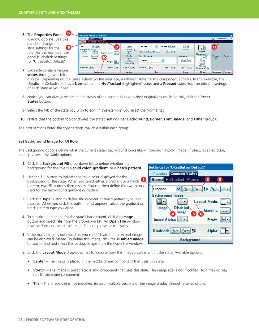
6. The Properties Panel window displays. Use thispanel to change the style settings for the role. For this example, thepanel is labeled: Settingsfor ‘UltraButtonDefault’
7. Each role contains various states through which it displays. Depending on the user’s actions on the interface, a different state for the component appears. In this example, the UltraButtonDefault role has a Normal state, a HotTracked (highlighted) state, and a Pressed state. You can edit the settings of each state as you need.
8. Notice you can always restore all the states of the current UI role to their original values. To do this, click the Reset States button.
9. Select the tab of the state you wish to edit. In this example, you select the Normal tab.
10. Notice that the bottom toolbar divides the state’s settings into Background, Border, Font, Image, and Other groups.
The next sections detail the style settings available within each group.
Set Background Image for UI Role
The Background options define what the current state’s background looks like – including fill color, image (if used), disabled color, and alpha level. Available options:
1. Click the Background Fill drop-down list to define whether the background for the role is a solid color, gradient, or a hatch pattern.
2. Use the Fill button to indicate the main color displayed for the background of the state. When you select either a gradient or a hatch pattern, two Fill buttons then display. You can then define the two colors used for the background gradient or pattern.
3. Click the Type button to define the gradient or hatch pattern type that displays. When you click this button, a list appears; select the gradient or hatch pattern type you want.
4. To substitute an image for the state’s background, click the Image button and select File from the drop-down list. An Open File windowdisplays. Find and select the image file that you want to display.
5. If the main image is not available, you can indicate that a second image can be displayed instead. To define this image, click the Disabled Imagebutton to find and select this backup image from the Open File window.
6. Click the Layout Mode drop-down list to indicate how this image displays within the state. Available options:
• Center – The image is placed in the middle of any component that uses this state.
• Stretch – The image is pulled across any component that uses this state. The image size is not modified, so it may or may not fill the entire component.
• Tile – The image size is not modified. Instead, multiple versions of the image display through a series of tiles.
CHAPTER 2 | STYLING AND THEMES
28 | EPICOR SOFTWARE CORPORATION
10
8
6
79
1
64
2 3
5

7. If you select the Stretchedlayout mode, the Margins button displays. Click this button to display the StretchMargins Editor.
8. Use the Top, Right, Bottom and Left values to define themargins, in pixels, forthe image.
9. When you finish, click OK.
10. You return to the Properties Panel.
11. Click the Image Alpha drop-down list to select how the image displays. Available options:
• UseAlphaLevel – Select this option to use the Alpha Level defined on the Other section of the Properties Panel. For more information, review the UI Roles – Other section later in this chapter.
• Opaque – Users see this image exactly as it normally appears.
• Transparent – Users can see through the image.
12. Use the Disabled Fill button to select what color is used when the main selected color is not available. If the Background Fill is for a gradient or a hatch pattern, a second Disabled Fill button becomes available. Use this button to select a second color to use when the second gradient or hatch pattern color is not available.
13. Click the Alpha drop-down list to select how the background fill colors display. Available options:
• UseAlphaLevel – Select this option to use the Alpha Level defined on the Other section of the Properties Panel. For more information, review the UI Roles – Other section later in this chapter.
• Opaque – Users see this color exactly as it normally appears.
• Transparent – Users can see through this color.
STYLING AND THEMES | CHAPTER 2
EPICOR SOFTWARE CORPORATION | 29
9
7
1312
8
10
11
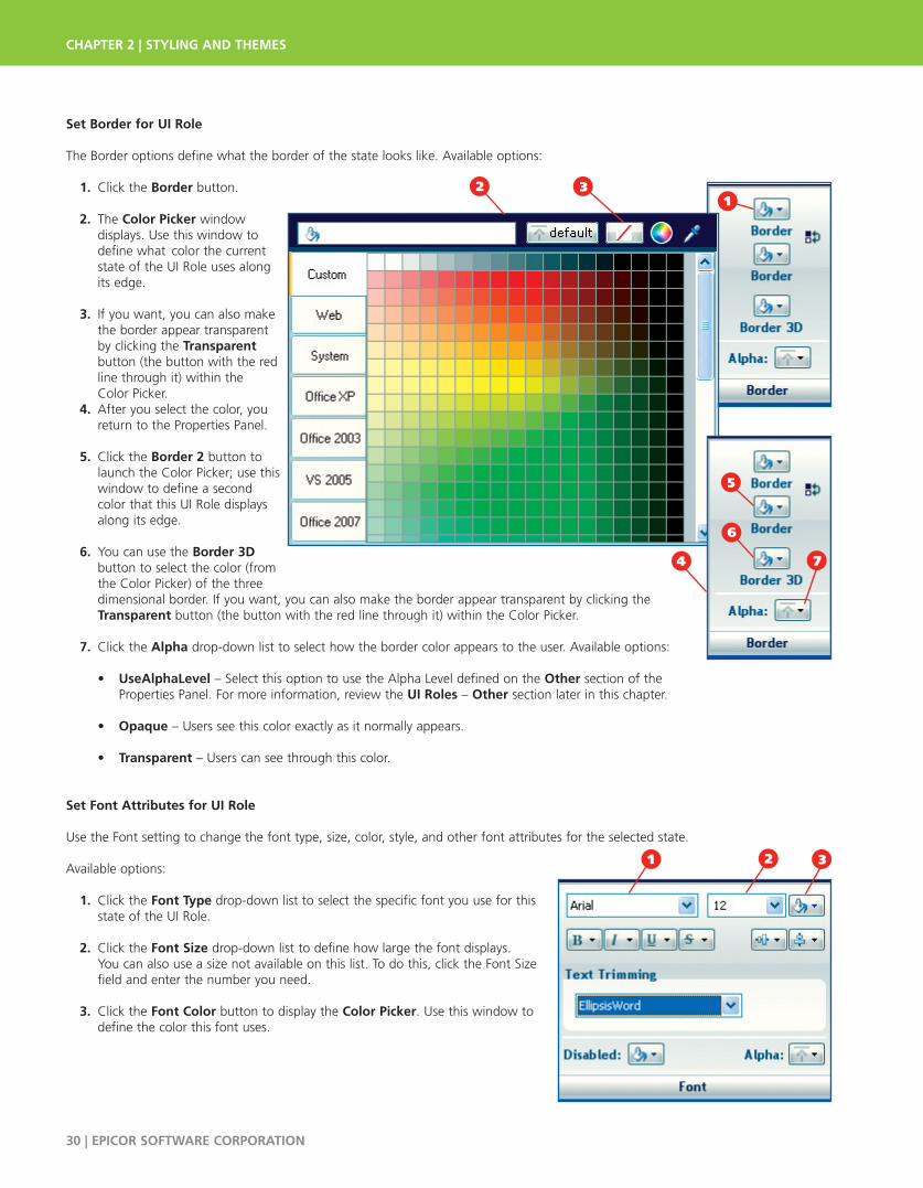
Set Border for UI Role
The Border options define what the border of the state looks like. Available options:
1. Click the Border button.
2. The Color Picker window displays. Use this window to define what color the currentstate of the UI Role uses alongits edge.
3. If you want, you can also make the border appear transparent by clicking the Transparentbutton (the button with the red line through it) within the Color Picker.
4. After you select the color, you return to the Properties Panel.
5. Click the Border 2 button to launch the Color Picker; use this window to define a second color that this UI Role displays along its edge.
6. You can use the Border 3D button to select the color (from the Color Picker) of the three dimensional border. If you want, you can also make the border appear transparent by clicking the Transparent button (the button with the red line through it) within the Color Picker.
7. Click the Alpha drop-down list to select how the border color appears to the user. Available options:
• UseAlphaLevel – Select this option to use the Alpha Level defined on the Other section of the Properties Panel. For more information, review the UI Roles – Other section later in this chapter.
• Opaque – Users see this color exactly as it normally appears.
• Transparent – Users can see through this color.
Set Font Attributes for UI Role
Use the Font setting to change the font type, size, color, style, and other font attributes for the selected state.
Available options:
1. Click the Font Type drop-down list to select the specific font you use for this state of the UI Role.
2. Click the Font Size drop-down list to define how large the font displays. You can also use a size not available on this list. To do this, click the Font Size field and enter the number you need.
3. Click the Font Color button to display the Color Picker. Use this window to define the color this font uses.
CHAPTER 2 | STYLING AND THEMES
30 | EPICOR SOFTWARE CORPORATION
1
4
2
7
5
3
6
31 2
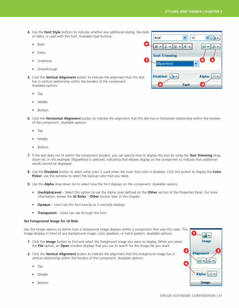
4. Use the Font Style buttons to indicate whether any additional styling, like bold or italics, is used with this font. Available style buttons:
• Bold
• Italics
• Underline
• Strikethrough
5. Click the Vertical Alignment button to indicate the alignment that this text has in vertical relationship within the borders of the component. Available options:
• Top
• Middle
• Bottom
6. Click the Horizontal Alignment button to indicate the alignment that this text has in horizontal relationship within the borders of the component. Available options:
• Top
• Middle
• Bottom
7. If the text does not fit within the component borders, you can specify how to display this text by using the Text Trimming drop-down list. In this example, EllipseWord is selected, indicating that ellipses display on the component to indicate that additional words cannot be displayed.
8. Use the Disabled button to select what color is used when the main font color is disabled. Click this button to display the ColorPicker; use this window to select the backup color that you need.
9. Use the Alpha drop-down list to select how the font displays on the component. Available options:
• UseAlphaLevel – Select this option to use the Alpha Level defined on the Other section of the Properties Panel. For more information, review the UI Roles – Other section later in this chapter.
• Opaque – Users see this font exactly as it normally displays.
• Transparent – Users can see through this font.
Set Foreground Image for UI Role
Use the Image options to define how a foreground image displays within a component that uses this state. Thisimage displays in front of any background image, color, gradient, or hatch pattern. Available options:
1. Click the Image button to find and select the foreground image you want to display. When you select the File option, an Open window displays that you use to search for the image file you want.
2. Click the Vertical Alignment button to indicate the alignment that this foreground image has in vertical relationship within the borders of the component. Available options:
• Top
• Middle
• Bottom
STYLING AND THEMES | CHAPTER 2
EPICOR SOFTWARE CORPORATION | 31
6
4
9
57
8
1
23
4
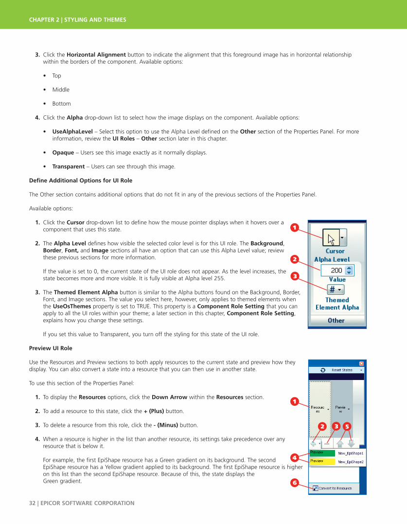
3. Click the Horizontal Alignment button to indicate the alignment that this foreground image has in horizontal relationship within the borders of the component. Available options:
• Top
• Middle
• Bottom
4. Click the Alpha drop-down list to select how the image displays on the component. Available options:
• UseAlphaLevel – Select this option to use the Alpha Level defined on the Other section of the Properties Panel. For more information, review the UI Roles – Other section later in this chapter.
• Opaque – Users see this image exactly as it normally displays.
• Transparent – Users can see through this image.
Define Additional Options for UI Role
The Other section contains additional options that do not fit in any of the previous sections of the Properties Panel.
Available options:
1. Click the Cursor drop-down list to define how the mouse pointer displays when it hovers over a component that uses this state.
2. The Alpha Level defines how visible the selected color level is for this UI role. The Background, Border, Font, and Image sections all have an option that can use this Alpha Level value; review these previous sections for more information.
If the value is set to 0, the current state of the UI role does not appear. As the level increases, the state becomes more and more visible. It is fully visible at Alpha level 255.
3. The Themed Element Alpha button is similar to the Alpha buttons found on the Background, Border, Font, and Image sections. The value you select here, however, only applies to themed elements when the UseOsThemes property is set to TRUE. This property is a Component Role Setting that you can apply to all the UI roles within your theme; a later section in this chapter, Component Role Setting, explains how you change these settings.
If you set this value to Transparent, you turn off the styling for this state of the UI role.
Preview UI Role
Use the Resources and Preview sections to both apply resources to the current state and preview how they display. You can also convert a state into a resource that you can then use in another state.
To use this section of the Properties Panel:
1. To display the Resources options, click the Down Arrow within the Resources section.
2. To add a resource to this state, click the + (Plus) button.
3. To delete a resource from this role, click the - (Minus) button.
4. When a resource is higher in the list than another resource, its settings take precedence over any resource that is below it.
For example, the first EpiShape resource has a Green gradient on its background. The second EpiShape resource has a Yellow gradient applied to its background. The first EpiShape resource is higher on this list than the second EpiShape resource. Because of this, the state displays the Green gradient.
CHAPTER 2 | STYLING AND THEMES
32 | EPICOR SOFTWARE CORPORATION
1
2
3
4
2 5
6
1
3
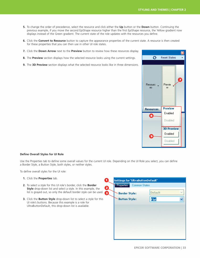
5. To change the order of precedence, select the resource and click either the Up button or the Down button. Continuing the previous example, if you move the second EpiShape resource higher than the first EpiShape resource, the Yellow gradient now displays instead of the Green gradient. The current state of the role updates with the resources you define.
6. Click the Convert to Resource button to capture the appearance properties of the current state. A resource is then created for these properties that you can then use in other UI role states.
7. Click the Down Arrow next to the Preview button to review how these resources display.
8. The Preview section displays how the selected resource looks using the current settings.
9. The 3D Preview section displays what the selected resource looks like in three dimensions.
Define Overall Styles for UI Role
Use the Properties tab to define some overall values for the current UI role. Depending on the UI Role you select, you can define a Border Style, a Button Style, both styles, or neither styles.
To define overall styles for the UI role:
1. Click the Properties tab.
2. To select a style for this UI role's border, click the Border Style drop-down list and select a style. In this example, the list is grayed out, so only the default border style can be used.
3. Click the Button Style drop-down list to select a style for this UI role’s buttons. Because this example is a role for UltraButtonDefault, this drop-down list is available.
STY
STYLING AND THEMES | CHAPTER 2
EPICOR SOFTWARE CORPORATION | 33
8
7
9
1
3
2

Manage Component Role Settings
Use the Component Role Settings features to style both Inbox Components
and Infragistics® Components. Inbox Components are interface items not
included within the Infragistics® component set. Both component types havesettings that they share with other component role settings (CommonComponent Properties); they also have settings available only within individual components (Component Specific Properties).
To navigate and select a specific component role setting, do the following:
1. Click the Roles tab.
2. Open the Component Role Settings folder.
3. You can select All Components, Inbox Components, and Infragistics Components. In this example, you select the Inbox Components node.
4. Select the component you want to modify. In this example, you select the Inbox CheckBox component.
5. The Properties Panel displays. In this example, it is the Settings for “Inbox CheckBox” window.
You can now modify these settings as you need.
Set Common Component Properties
Use the first section of this window to modify any properties shared across all components. Available options:
1. Click the Categorized button to display the different categories available for the selected setting. In this example, only one behavior is available: the Resolution Order.
2. Notice that a Description of the selected property displays at the bottom of this section.
3. To display these properties in alphabetical order, click the Alphabetical button.
4. Click the Property Pages button to view any page information.
CHAPTER 2 | STYLING AND THEMES
34 | EPICOR SOFTWARE CORPORATION
Whether or not you change the common or component specific properties, you are only changingthe style of the currently selected component role.
1
2
5
3
4
1
4
5
3
2
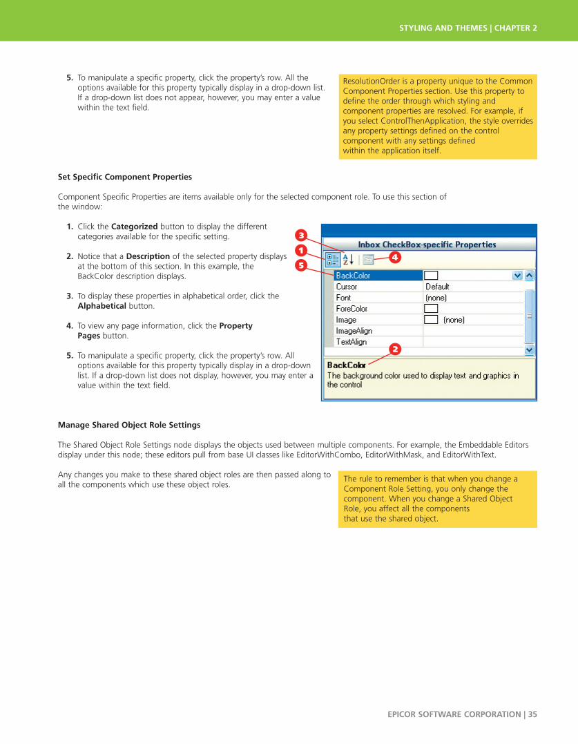
5. To manipulate a specific property, click the property’s row. All theoptions available for this property typically display in a drop-down list. If a drop-down list does not appear, however, you may enter a valuewithin the text field.
Set Specific Component Properties
Component Specific Properties are items available only for the selected component role. To use this section of the window:
1. Click the Categorized button to display the different categories available for the specific setting.
2. Notice that a Description of the selected property displays at the bottom of this section. In this example, the BackColor description displays.
3. To display these properties in alphabetical order, click theAlphabetical button.
4. To view any page information, click the Property Pages button.
5. To manipulate a specific property, click the property’s row. All options available for this property typically display in a drop-down list. If a drop-down list does not display, however, you may enter a value within the text field.
Manage Shared Object Role Settings
The Shared Object Role Settings node displays the objects used between multiple components. For example, the Embeddable Editorsdisplay under this node; these editors pull from base UI classes like EditorWithCombo, EditorWithMask, and EditorWithText.
Any changes you make to these shared object roles are then passed along toall the components which use these object roles.
STYLING AND THEMES | CHAPTER 2
EPICOR SOFTWARE CORPORATION | 35
ResolutionOrder is a property unique to the CommonComponent Properties section. Use this property todefine the order through which styling and component properties are resolved. For example, ifyou select ControlThenApplication, the style overridesany property settings defined on the control component with any settings defined within the application itself.
14
2
5
3
The rule to remember is that when you change aComponent Role Setting, you only change thecomponent. When you change a Shared ObjectRole, you affect all the components that use the shared object.

To navigate and select a shared object role setting:
1. Click the Roles tab.
2. Open the Shared Object Role Settings folder.
3. All the shared object roles display. Select the setting you want to modify. In this example, you select the DragDropIndicatorManager setting.
4. The Properties Panel displays. You can now make the changes you need to this component.
Set Specific Properties for Shared Object Role Settings
This section displays properties shared between several components. To use this section of the window:
1. Click the Categorized button to display the different categories available for the specific shared object setting.
2. Notice that a Description of the selected shared object property displays at the bottom of this section. In this example, BottomArrowImage displays.
3. To display these shared object properties in alphabetical order, click the Alphabetical button.
4. To view any page information, click the Property Pages button.
5. To manipulate a specific property, click the property’s row. All the options available for this property typically display in a drop-down list. If a drop-down list does not display, however, you may enter a value within the text field.
CHAPTER 2 | STYLING AND THEMES
36 | EPICOR SOFTWARE CORPORATION
4
1
2
3
14
2
5
3

Components in the Used By Section
The Used By section of the Runtime Stylist displays all the components that appear using the selected UI role. When you select an itemfrom this list, you display the Component Role Settings window, where you can make additional changes to this component.
Modify Components in the Used By Section
To leverage this functionality:
1. Use the Tree View to navigate to the role you want.
2. Select the UI Role you want to view. In this example, you select the Button role.
3. All the components that use this role display in the Used By section.
4. Select one of these components. In this example, you select the top UltraButton item.
5. The Component Role Settings window displays. Make the changes you need. For more information about the options on this window, review the previous Manage Component Role Settings section.
Role Selection
As you make changes to the current theme, you can navigate through the user interface to see how the changes look. Because theRuntime Stylist is active, however, you can also launch a component Property Panel to immediately make the changes you need.
Use this tool to further refine your style. You can then make specific runtime changes to selected components as you see them on the interface.
STYLING AND THEMES | CHAPTER 2
EPICOR SOFTWARE CORPORATION | 37
5
1
2
4 3
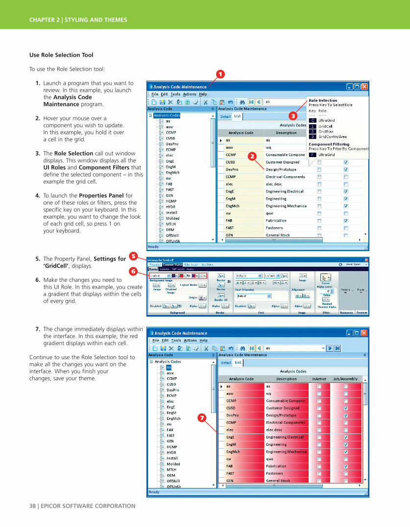
Use Role Selection Tool
To use the Role Selection tool:
1. Launch a program that you want to review. In this example, you launch the Analysis CodeMaintenance program.
2. Hover your mouse over a component you wish to update. In this example, you hold it over a cell in the grid.
3. The Role Selection call out window displays. This window displays all the UI Roles and Component Filters that define the selected component – in this example the grid cell.
4. To launch the Properties Panel for one of these roles or filters, press the specific key on your keyboard. In this example, you want to change the look of each grid cell, so press 1 on your keyboard.
5. The Property Panel, Settings for ‘GridCell’, displays.
6. Make the changes you need to this UI Role. In this example, you create a gradient that displays within the cells of every grid.
7. The change immediately displays within the interface. In this example, the red gradient displays within each cell.
Continue to use the Role Selection tool tomake all the changes you want on the interface. When you finish your changes, save your theme.
CHAPTER 2 | STYLING AND THEMES
38 | EPICOR SOFTWARE CORPORATION
1
2
7
5
3
6

Style Filter ManagementUse Style Filter Management to create filters to use within a specific theme. You can create child style filters based on the original, or parent, theme. These filters limit these child styles so that their styling is only used within a specific company, plant, language, or program.
The style filter functionality supports many styling combinations for the same theme, as you can create a child style filter that is thenthe child of another child style filter. This section also describes how you can create style filter combinations.
Launch Style Filter Manager
To launch this program:
1. From the Options menu, select Styling.
2. Select the Style Filter Manager.
Create a Child Style Filter
To use Style Filter Management:
1. The filters available for the current theme display in the Tree View.
2. If you want to create a new style filter for a different theme, click the Loadbutton to find and select the .isl file you want.
3. To create a child style filter, first highlight the parent style you want on the Tree View. In this example, the Default style is selected.
4. Right-click your mouse to display the context menu. Select the CreateChild Style command.
STYLING AND THEMES | CHAPTER 2
EPICOR SOFTWARE CORPORATION | 39
1
2
4
2
3
1

5. A (New) style filter displays on the Tree View. Enter a StyleSetName for this child style filter. In this example, you enter Epicor Mfg - Chicago. The new Name displays on the Tree View.
6. Select a FilterType. Availableoptions:
• Company
• Plant
• Language
• Application
• None
In this example, you select Company; you can now create a child style filter for a specific company within the default theme.
7. Define what item is affected by this filter. To do this, click the FilterTypeSelect drop-down list. Depending on the filter, different items display. In this example, all the companies within the application are listed, so you select the Epicor Mfg - Chicago option. When users switch to this company, the interface displays using this child style.
8. The FilterValue displays the name that the application uses to identify the selected item. In this example, the company ID, VN30C, displays.
9. You can also define the EpiResources that use this child style filter. If youneed, you could enter values in theseproperties to limit this child style tospecific interface items, like panels, theOK shape, and so on. In this example,you leave these properties blank.
10. The EpiStyles section defines the additional interface components that use this style filter – like the Message Box and the Navigation Control. If you need, you can enter additional style values in these fields.
11. The Description area displays an explanation for the currently selected property. This text changes as different items are selected.
12. You next must select the Create resources if missing check box. This indicates that you can create the main EpiResource for this style filter.
13. Click Save.11
CHAPTER 2 | STYLING AND THEMES
40 | EPICOR SOFTWARE CORPORATION
8
6
9
5
13
12
7
10
11
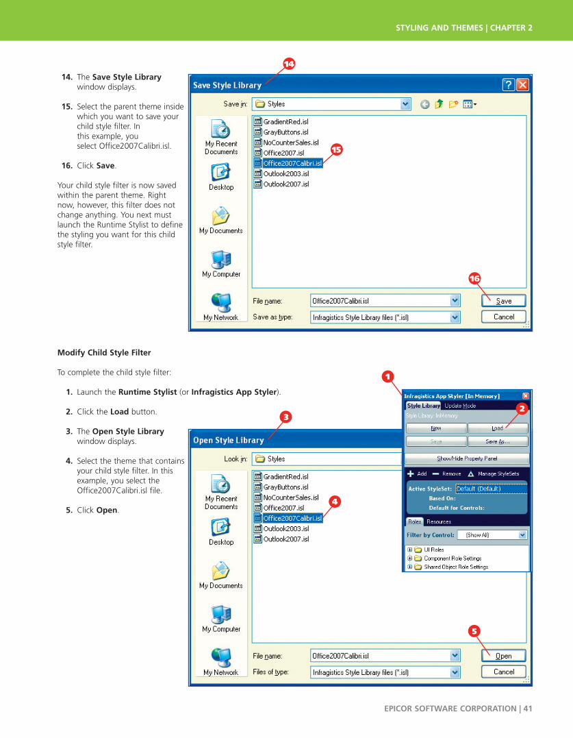
14. The Save Style Library window displays.
15. Select the parent theme inside which you want to save your child style filter. In this example, you select Office2007Calibri.isl.
16. Click Save.
Your child style filter is now savedwithin the parent theme. Right now, however, this filter does notchange anything. You next mustlaunch the Runtime Stylist to definethe styling you want for this childstyle filter.
Modify Child Style Filter
To complete the child style filter:
1. Launch the Runtime Stylist (or Infragistics App Styler).
2. Click the Load button.
3. The Open Style Library window displays.
4. Select the theme that contains your child style filter. In this example, you select the Office2007Calibri.isl file.
5. Click Open.
STYLING AND THEMES | CHAPTER 2
EPICOR SOFTWARE CORPORATION | 41
14
15
16
2
5
1
4
3
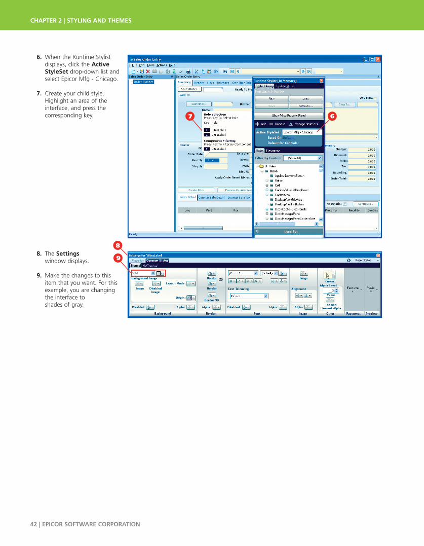
6. When the Runtime Stylistdisplays, click the ActiveStyleSet drop-down list andselect Epicor Mfg - Chicago.
7. Create your child style. Highlight an area of the interface, and press the corresponding key.
8. The Settings window displays.
9. Make the changes to this item that you want. For this example, you are changing the interface to shades of gray.
7 6
CHAPTER 2 | STYLING AND THEMES
42 | EPICOR SOFTWARE CORPORATION
67
8
9

10. To see how this styling choice looks, on the Main Menu, launch a program within the Epicor Mfg - Chicago company.
11. All the programs within this company display using this child style.
STYLING
STYLING AND THEMES | CHAPTER 2
EPICOR SOFTWARE CORPORATION | 43
10
11

12. Access another company, and in this example, you navigate to Epicor Corporation and launch Sales Order Entry.
13. Notice that the default styling displays within this program. This happens because the child style filter applies only to the Epicor Mfg
- Chicago company.
You can continue to create childstyles for all the other companieswithin your organization. By leveraging this functionality, youmake it easier for users to identifydifferent companies when theyswitch between them.
CHAPTER 2 | STYLING AND THEMES
44 | EPICOR SOFTWARE CORPORATION
12
13
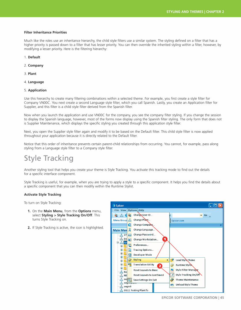
Filter Inheritance Priorities
Much like the roles use an inheritance hierarchy, the child style filters use a similar system. The styling defined on a filter that has ahigher priority is passed down to a filter that has lesser priority. You can then override the inherited styling within a filter, however, bymodifying a lesser priority. Here is the filtering hierarchy:
1. Default
2. Company
3. Plant
4. Language
5. Application
Use this hierarchy to create many filtering combinations within a selected theme. For example, you first create a style filter forCompany VN00C. You next create a second Language style filter, which you call Spanish. Lastly, you create an Application filter forSupplier, and this filter is a child style filter derived from the Spanish filter.
Now when you launch the application and use VN00C for the company, you see the company filter styling. If you change the sessionto display the Spanish language, however, most of the forms now display using the Spanish filter styling. The only form that does notis Supplier Maintenance, which displays the specific styling you created through this application style filter.
Next, you open the Supplier style filter again and modify it to be based on the Default filter. This child style filter is now appliedthroughout your application because it is directly related to the Default filter.
Notice that this order of inheritance prevents certain parent-child relationships from occurring. You cannot, for example, pass alongstyling from a Language style filter to a Company style filter.
Style TrackingAnother styling tool that helps you create your theme is Style Tracking. You activate this tracking mode to find out the details for a specific interface component.
Style Tracking is useful, for example, when you are trying to apply a style to a specific component. It helps you find the details abouta specific component that you can then modify within the Runtime Stylist.
Activate Style Tracking
To turn on Style Tracking:
1. On the Main Menu, from the Options menu, select Styling > Style Tracking On/Off. This turns Style Tracking on.
2. If Style Tracking is active, the icon is highlighted.
STYLING AND THEMES | CHAPTER 2
EPICOR SOFTWARE CORPORATION | 45
2
1
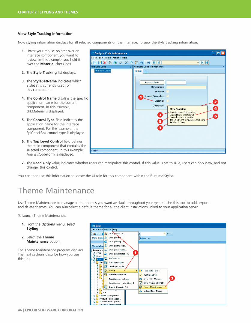
View Style Tracking Information
Now styling information displays for all selected components on the interface. To view the style tracking information:
1. Hover your mouse pointer over an interface component you want to review. In this example, you hold it over the Material check box.
2. The Style Tracking list displays.
3. The StyleSetName indicates which StyleSet is currently used for this component.
4. The Control Name displays the specific application name for the current component. In this example, chkMaterial is displayed.
5. The Control Type field indicates the application name for the interface component. For this example, the EpiCheckBox control type is displayed.
6. The Top Level Control field defines the main component that contains the selected component. In this example, AnalysisCodeForm is displayed.
7. The Read Only value indicates whether users can manipulate this control. If this value is set to True, users can only view, and notchange, this control.
You can then use this information to locate the UI role for this component within the Runtime Stylist.
Theme MaintenanceUse Theme Maintenance to manage all the themes you want available throughout your system. Use this tool to add, export, and delete themes. You can also select a default theme for all the client installations linked to your application server.
To launch Theme Maintenance:
1. From the Options menu, select Styling.
2. Select the Theme Maintenance option.
The Theme Maintenance program displays.The next sections describe how you use this tool.
CHAPTER 2 | STYLING AND THEMES
46 | EPICOR SOFTWARE CORPORATION
1
5
3
4
6
2
1
2
7
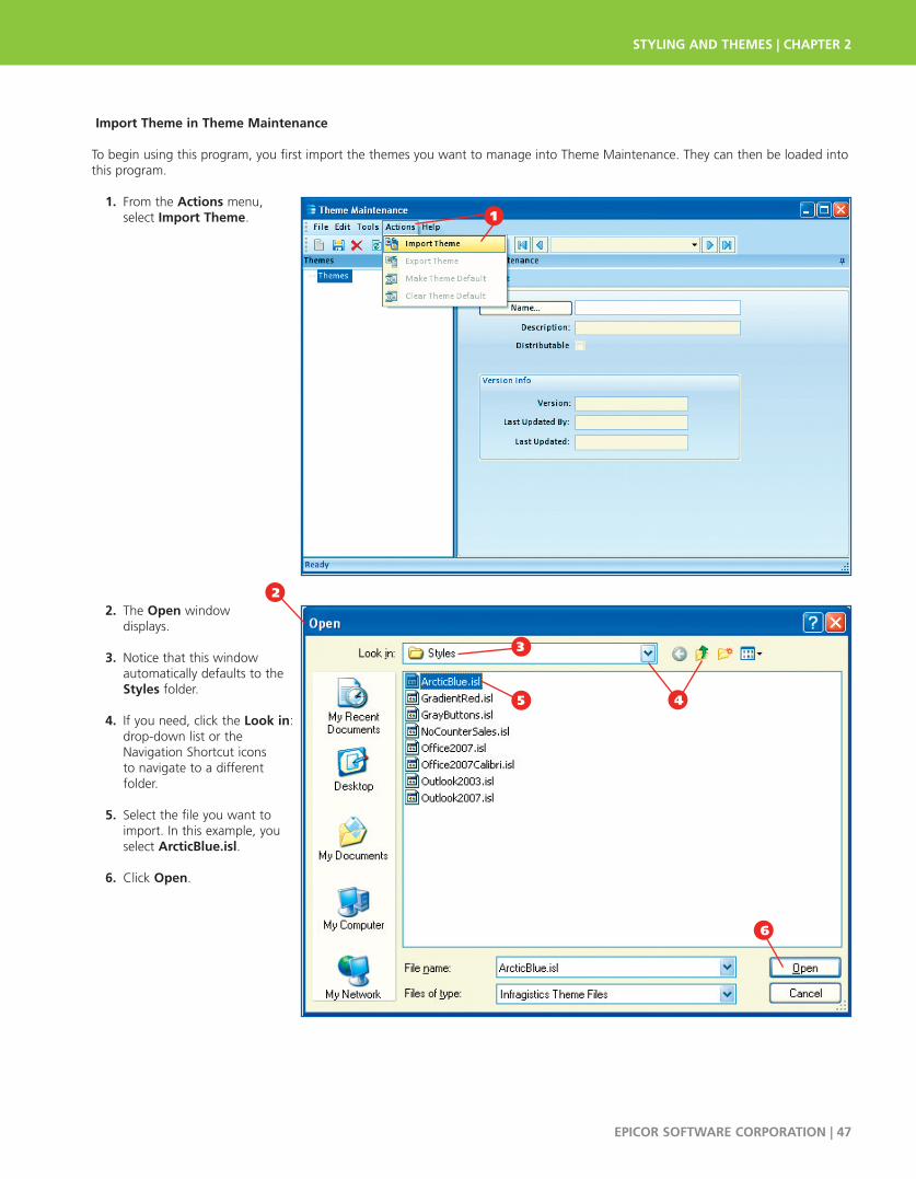
Import Theme in Theme Maintenance
To begin using this program, you first import the themes you want to manage into Theme Maintenance. They can then be loaded intothis program.
1. From the Actions menu, select Import Theme.
2. The Open window displays.
3. Notice that this window automatically defaults to the Styles folder.
4. If you need, click the Look in: drop-down list or the Navigation Shortcut icons to navigate to a different folder.
5. Select the file you want to import. In this example, you select ArcticBlue.isl.
6. Click Open.
STYLING AND THEMES | CHAPTER 2
EPICOR SOFTWARE CORPORATION | 47
1
3
4
6
2
5

8. If the theme was successfully imported, this confirmation message displays. Click OK.
9. You return to Theme Maintenance. Click the Name button.
10. The Theme Search program displays.
11. Click Search.
12. Within the Search Results grid, select the theme or themes you want to import.
13. If you want to import all the available themes, click the Select All button.
14. Click OK.
CHAPTER 2 | STYLING AND THEMES
48 | EPICOR SOFTWARE CORPORATION
9
8
10
11
12
14 13

15. The selected themes display within Theme Maintenance.
Manage Themes in Theme Maintenance
To manage all the imported themes:
1. In the Tree View, select the theme you want.
2. The Name field displays the filename for the selected .isl file. If you need, you can change the style’s name.
3. The Description field displays the brief explanation of the selected theme. If you want, you can enter a different description in this field.
4. To make this theme available to all your client installations, select the Distributablecheck box. This theme is automatically downloaded to all client machines within your system.
If users set up their Configuration Files to use specific server themes, the corresponding theme is automatically loaded when the user logs into the client application. They do this by defining the Styleparameter within the Configuration File. Any changes made on the server to these themes (through the Runtime Stylist) are automatically updated on all client applications.
STYLING AND THEMES | CHAPTER 2
EPICOR SOFTWARE CORPORATION | 49
15
18
6
4
2
7
5
3

Likewise, if any customized program is set up to use a specific servertheme, the corresponding theme is automatically loaded when a userlaunches the customization. As previously described, any changes madeon the server to these themes (through the Runtime Stylist) areautomatically updated on all client applications.
15. The Version field displays the theme version number. The application
uses this number to identify the style.
6. The Last Updated By field displays the identifier of the user who previously updated the theme.
7. The Last Updated field displays the date on which the theme was last modified.
8. To record your changes to the theme, click Save on the Standard toolbar.
Set up Default Theme in Theme Maintenance
To indicate that the current theme is the Default Theme for the application:
1. Verify that the Distributable check box is selected.
2. From the Actions menu, select Make Theme Default.
3. A window displays indicating that this theme is selected as the default. Click OK.
2
CHAPTER 2 | STYLING AND THEMES
50 | EPICOR SOFTWARE CORPORATION
For more information about the Style parameterwithin the Configuration File, review Chapter 1:Startup Configurations. For more information aboutthe styling override options on a customized control,review Chapter 5: Advanced Customization.
1
3
2

4. The Default Theme icon nowdisplays on the Detail sheet.Any client installations set upto display the defaultautomatically uses this theme.
5. You can also remove the Default status from a theme. To do this, from the Actions menu, select Clear Theme Default.
STYLING AND THEMES |
STYLING AND THEMES | CHAPTER 2
EPICOR SOFTWARE CORPORATION | 51
Only one theme can beselected as the default foryour application. If youselect another theme asthe default, the previoustheme is no longerdefined as the default.
5
4

6. The Default Theme icon isno longer displayed next tothe Name field.
7. To record your changes to the theme, click Save on the Standard toolbar.
Export Theme in Theme Maintenance
If you have created a theme that you want to make available throughout your organization, you can export it into a folder you select.
To export a theme into a folder:
1. In the Tree View, select the theme you want to export.
2. From the Actions menu,select Export Theme.
8
CHAPTER 2 | STYLING AND THEMES
52 | EPICOR SOFTWARE CORPORATION
67
2
1
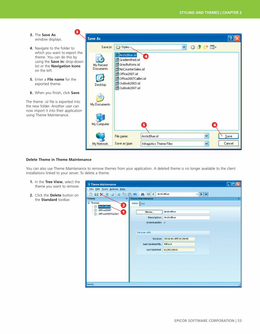
3. The Save As window displays.
4. Navigate to the folder to which you want to export the theme. You can do this by using the Save in: drop-down list or the Navigation Iconson the left.
5. Enter a File name for the exported theme.
6. When you finish, click Save.
The theme .isl file is exported intothe new folder. Another user cannow import it into their applicationusing Theme Maintenance.
Delete Theme in Theme Maintenance
You can also use Theme Maintenance to remove themes from your application. A deleted theme is no longer available to the clientinstallations linked to your server. To delete a theme:
1. In the Tree View, select the theme you want to remove.
2. Click the Delete button on the Standard toolbar.2
1
STYLING AND THEMES | CHAPTER 2
EPICOR SOFTWARE CORPORATION | 53
1
2
3
65
4

3. A message appears asking if you want to delete the record. Click Yes.
4. The theme no longer displays on the Tree View.
Default Theme RetrievalYou can restore the original defaulttheme by using the Unload StyleTheme command. All areas withinthe interface then automaticallyreturn to the default styling definedfor the application.
To use this feature:
1. From Options menu, select Styling.
2. Select Unload Style Theme.
The interface changes back to display the default theme.
CHAPTER 2 | STYLING AND THEMES
54 | EPICOR SOFTWARE CORPORATION
3
4
1
2
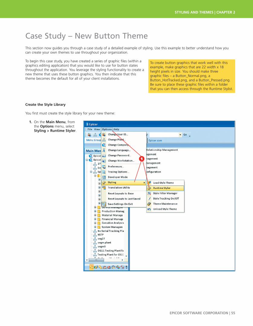
Case Study – New Button ThemeThis section now guides you through a case study of a detailed example of styling. Use this example to better understand how youcan create your own themes to use throughout your organization.
To begin this case study, you have created a series of graphic files (within agraphics editing application) that you would like to use for button statesthroughout the application. You leverage the styling functionality to create anew theme that uses these button graphics. You then indicate that this theme becomes the default for all of your client installations.
1Create the Style Library
You first must create the style library for your new theme:
1. On the Main Menu, from the Options menu, select Styling > Runtime Styler.
\
STYLING AND THEMES | CHAPTER 2
EPICOR SOFTWARE CORPORATION | 55
To create button graphics that work well with thisexample, make graphics that are 22 width x 18height pixels in size. You should make three graphic files – a Button_Normal.png, aButton_HotTracked.png, and a Button_Pressed.png.Be sure to place these graphic files within a folderthat you can then access through the Runtime Stylist.
1

2. The Runtime Stylist window displays.
3. Click the New button.
The new Style Library is created.
Define Component Role Settings
Now change some component role settings for the UltraButton component. These settingsare then applied to nearly all the buttons within the application. To define the ComponentRole Settings:
1. Click the Roles tab.
2. Expand the Component Role Settings node.
3. Expand the Infragistics Components node.
4. Select the UltraButton component.
5. The Property Panel, Settings for “UltraButton”, displays.
6. Change some Common Component Properties onthis window.
7. Set the UseFlatMode property to True.
CHAPTER 2 | STYLING AND THEMES
56 | EPICOR SOFTWARE CORPORATION
3
2
1
4
2
3
5 6
7
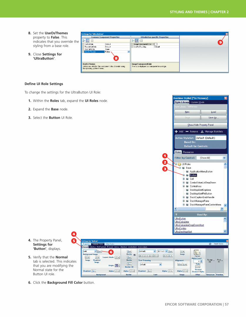
7 8. Set the UseOsThemes property to False. Thisindicates that you override thestyling from a base role.
9. Close Settings for 'UltraButton'.
Define UI Role Settings
To change the settings for the UltraButton UI Role:
1. Within the Roles tab, expand the UI Roles node.
2. Expand the Base node.
3. Select the Button UI Role.
4. The Property Panel, Settings for ‘Button’, displays.
5. Verify that the Normal tab is selected. This indicates that you are modifying the Normal state for the Button UI role.
6. Click the Background Fill Color button.
STYLING AND THEMES | CHAPTER 2
EPICOR SOFTWARE CORPORATION | 57
8
9
1
6
2
5
3
4

7. The Color Picker window displays.
8. Select the Transparent button (the button with the red line through it).
9. You return to the Settings for “Button” window. Notice that the Transparenticon now displays within the Background Fill Color button.
10. Within the Border section, click the Border Fill Color button.
11. The Color Picker window displays. Click the Transparent button again.
12. Now the Border Fill Color button displays the Transparent icon. H
APTER 2 | STYLING AND THE
MES
CHAPTER 2 | STYLING AND THEMES
58 | EPICOR SOFTWARE CORPORATION
9
12
7
8
10
11

Select and Size the Image
To select the specific button graphic file to use for the Normal state of this UI role:
1. Within the Background section, click the Background Image button and select theFile option. PTER
2. The Open window displays. Navigate to where you previously saved the three button states graphics you created.
APTER3. Select the first button state.
In this example, you select the Button_Normal.png file.
4. Click Open.
5. You return to the Settings for ‘Button’ window. APTER
6. Select the Layout Mode button.
7. Click the drop-down list, select the Stretched option.
STYLING AND THEMES |
STYLING AND THEMES | CHAPTER 2
EPICOR SOFTWARE CORPORATION | 59
1
6
2
7
5
3
4
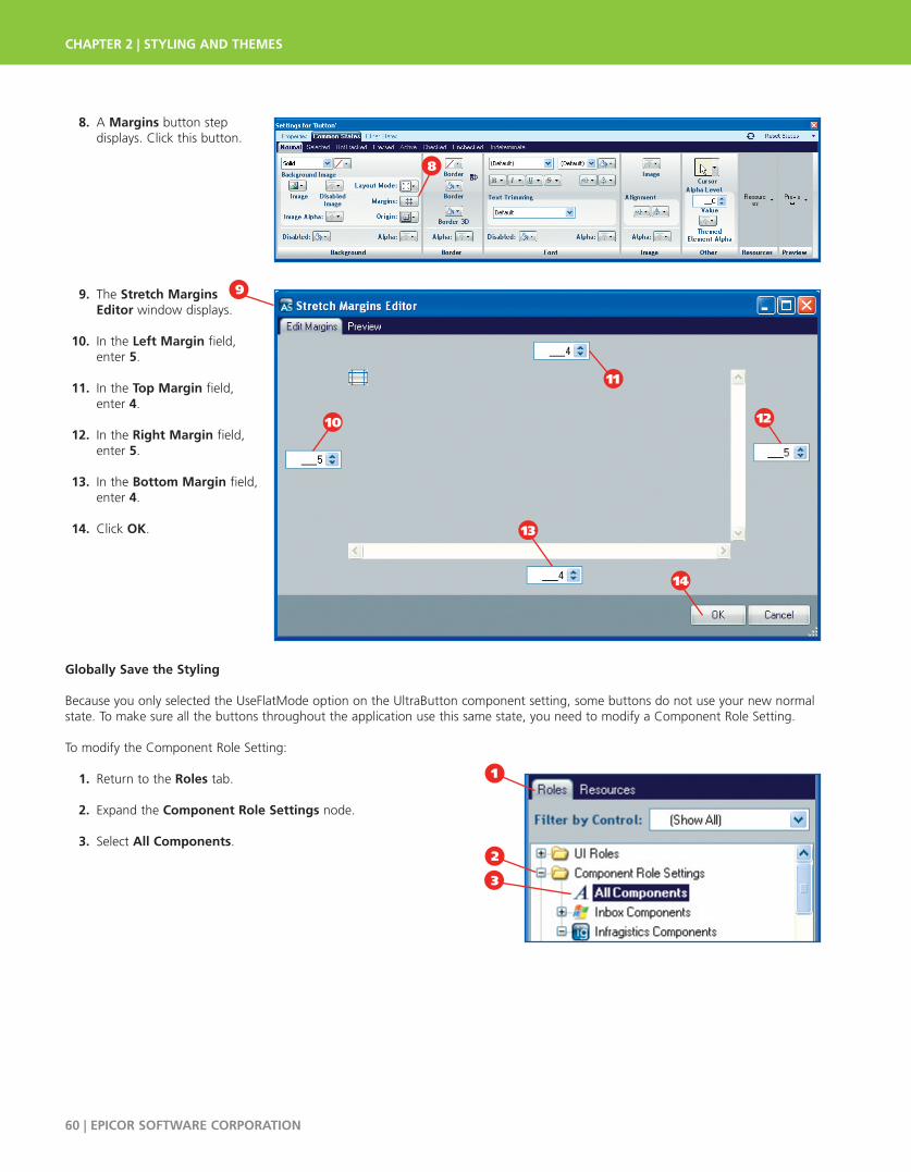
8. A Margins button step displays. Click this button.
9. The Stretch Margins Editor window displays.
10. In the Left Margin field, enter 5.
11. In the Top Margin field, enter 4.
12. In the Right Margin field, enter 5.
13. In the Bottom Margin field, enter 4.
14. Click OK.
Globally Save the Styling
Because you only selected the UseFlatMode option on the UltraButton component setting, some buttons do not use your new normalstate. To make sure all the buttons throughout the application use this same state, you need to modify a Component Role Setting.
To modify the Component Role Setting:
1. Return to the Roles tab.
2. Expand the Component Role Settings node.
3. Select All Components.
CHAPTER 2 | STYLING AND THEMES
60 | EPICOR SOFTWARE CORPORATION
8
9
10
11
12
13
14
1
3
2

4. The Settings for “All Components” window displays.
5. Set the UseFlatMode property to True.
6. Set the UseOsThemes property to False. This indicates that you override the styling from a base role.
Now all the buttons throughout the application use your new Normal state.
Modify Hot-Tracked State
Repeat these steps for the button component’s HotTracked state. During these steps, you indicate that your HotTracked graphic is usedfor this button state. Here’s how:
1. Return to the Roles tab and navigate to the Button component.
2. If you need, launch the Property Panel, Settings for ‘Button’, again. Be sure to select the Hot Tracked tab.
3. Set both the Background Fill Color and the Border Fill Color buttonsto Transparent.
4. Click the Image button and select your HotTracked.png file.
5. Select the Layout Mode to Stretched.
STYLING AND THEMES | CHAPTER 2
EPICOR SOFTWARE CORPORATION | 61
6
4
5
1
6
4
5
2
3

6. Click the Margins button and use these values for the margins:
• Left – 5
• Top – 4
• Right – 5
• Bottom – 4
You now have updated the HotTracked state for buttons throughout the application.
Modify Pressed State
To modify pressed state:
1. In the Property Panel, Settings for Button, click the Pressed tab.
2. Set both the Background Fill Color and the Border Fill Color buttonsto Transparent.
3. Click the Image button and select your Pressed.png file.
4. Select the Layout Mode to Stretched.
5. Click the Margins button and use these values for the margins:
• Left – 5
• Top – 4
• Right – 5
• Bottom – 4
You now have updated the Pressed state for buttons throughout the application.
CHAPTER 2 | STYLING AND THEMES
62 | EPICOR SOFTWARE CORPORATION
1
4
5
3 2

Save the Style Library
You have finished creating the button styling, so you must save this style library. It then becomes a theme you can select for the application. To save a style library:
1. Click the Style Library tab.
2. Click the Save As button.
3. The Save Style Library window displays.
4. Enter a File Name for this theme. For this example, you enter GrayButtons.isl.
5. Click Save.
Set New Theme as Default
The new theme is now ready tobecome the default look for all ofyour client installations. To set a newtheme as default using ThemeMaintenance:
1. On the Main Menu, from the Options menu, select Styling > Theme Maintenance.
STYLING AND THEMES | CHAPTER 2
EPICOR SOFTWARE CORPORATION | 63
1
2
3
4 5
1
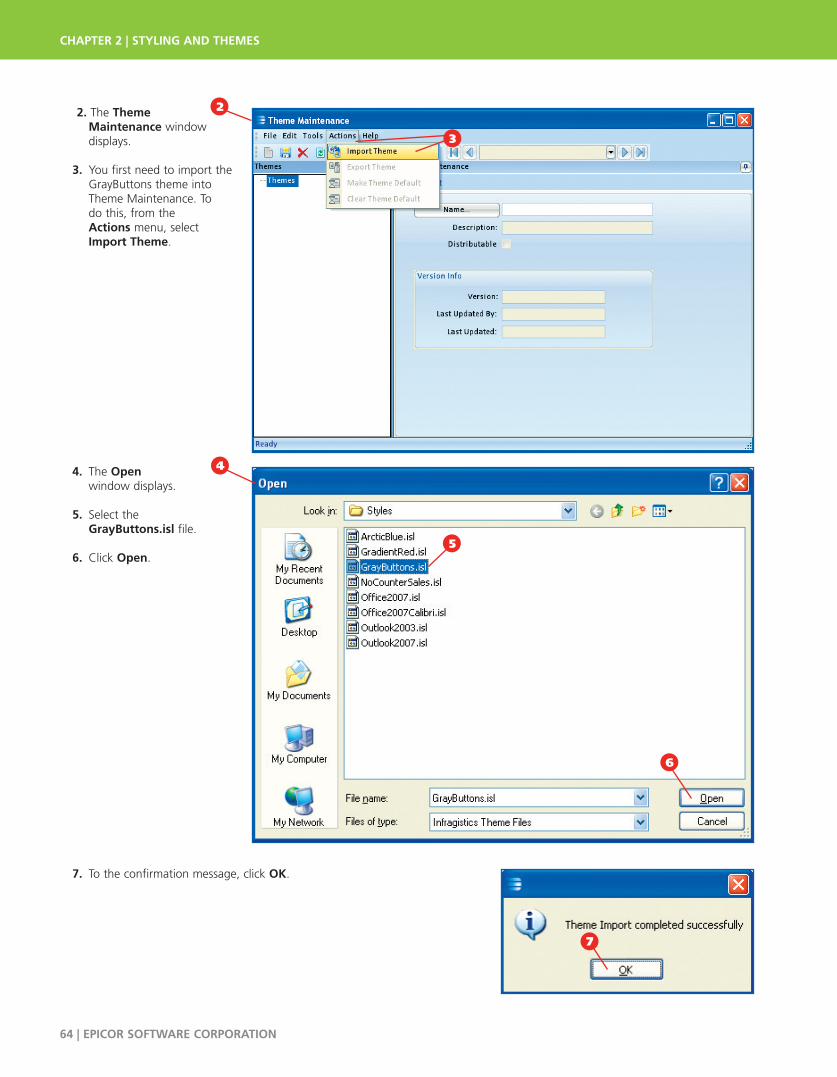
1 22. The Theme Maintenance windowdisplays.
3. You first need to import the GrayButtons theme into Theme Maintenance. To do this, from the Actions menu, select Import Theme.
4. The Open window displays.
5. Select the GrayButtons.isl file.
6. Click Open.
7. To the confirmation message, click OK. 7
CHAPTER 2 | STYLING AND THEMES
64 | EPICOR SOFTWARE CORPORATION
6
4
3
2
5
7

8. You return to Theme Maintenance. Click the Name button.
9. The Theme Search window displays.
10. Click Search.
11. From the Search Results grid, select the GrayButtons option.
12. Click OK.
STYLING AND THEMES | CHAPTER 2
EPICOR SOFTWARE CORPORATION | 65
10
8
9
11
12

13. The GrayButtons theme now displays within Theme Maintenance.
14. Select this theme’s Distributable check box. This indicates that all the client installations on your system can use this theme.
15. To make this theme the default for the application, from the Actions menu, select Make Theme Default.
16. To the confirmation message, click OK.
17. The Default Theme icondisplays. The GrayButtons theme is now the default for the application.
18. Click the Exit button to close Theme Maintenance.
CHAPTER 2 | STYLING AND THEMES
66 | EPICOR SOFTWARE CORPORATION
When a client is firstinstalled, it is set up to usethe default theme. If aclient installation nolonger uses the defaulttheme, however, you canchange this back within the ConfigurationSettings File. To do this,you update the Styles setting. To learn more,review the ConfigurationSettings File section within Chapter 1: Startup Configurations.
16
17
18
13 14
15
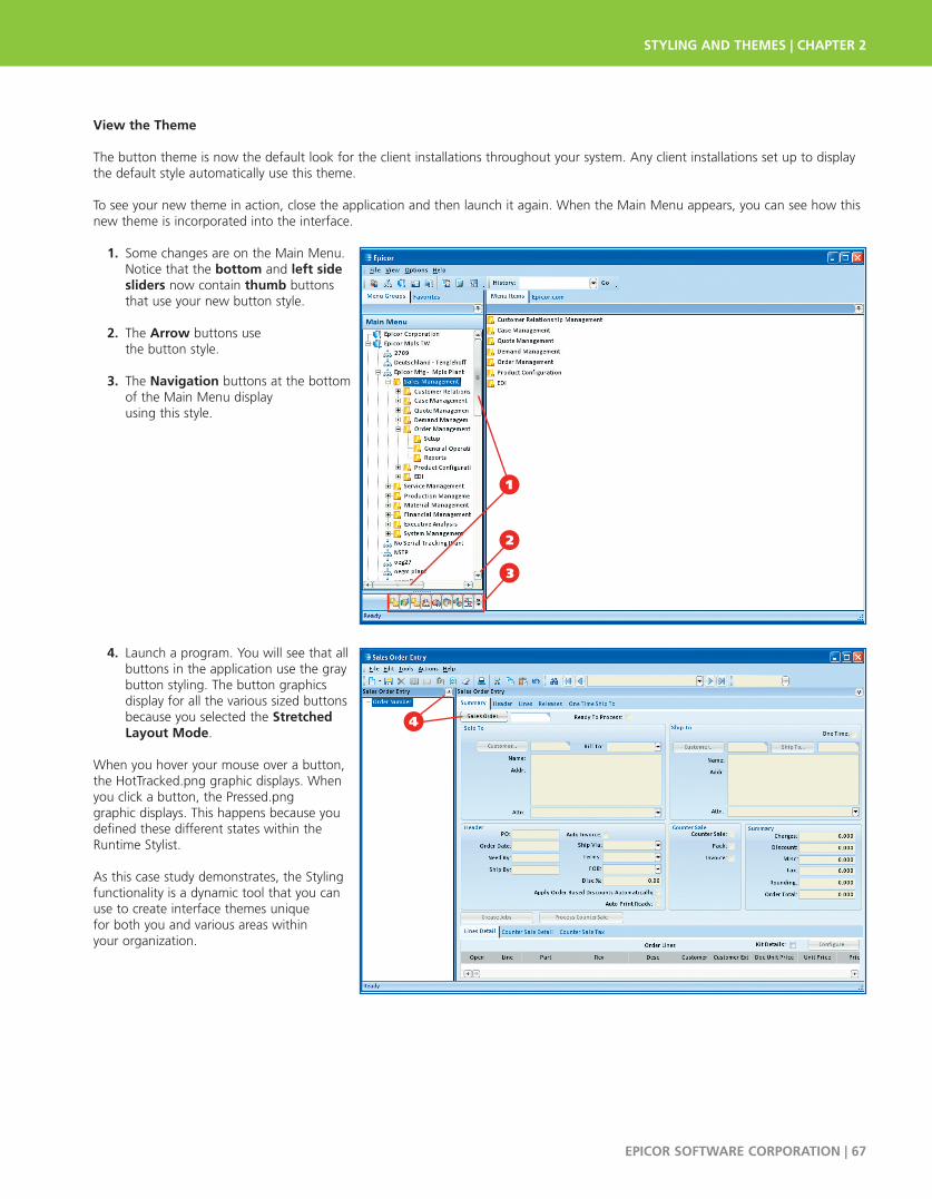
View the Theme
The button theme is now the default look for the client installations throughout your system. Any client installations set up to displaythe default style automatically use this theme.
To see your new theme in action, close the application and then launch it again. When the Main Menu appears, you can see how thisnew theme is incorporated into the interface.
1. Some changes are on the Main Menu. Notice that the bottom and left sidesliders now contain thumb buttons that use your new button style.
2. The Arrow buttons use the button style.
3. The Navigation buttons at the bottom of the Main Menu display using this style.
4. Launch a program. You will see that all buttons in the application use the gray button styling. The button graphics display for all the various sized buttons because you selected the StretchedLayout Mode.
When you hover your mouse over a button,the HotTracked.png graphic displays. Whenyou click a button, the Pressed.png graphic displays. This happens because youdefined these different states within theRuntime Stylist.
As this case study demonstrates, the Stylingfunctionality is a dynamic tool that you canuse to create interface themes unique for both you and various areas within your organization.
STYLING AND THEMES | CHAPTER 2
EPICOR SOFTWARE CORPORATION | 67
4
3
2
1

CHAPTER 2 | STYLING AND THEMES
68 | EPICOR SOFTWARE CORPORATION
PERSONALIZATION | CHAPTER 3
EPICOR SOFTWARE CORPORATION | 69
Chapter 3Personalization
Personalization is defined as any change made to the application that only affects a specific user’s interface. Every user has different needs. Some users may want to change the order of columns on a grid. Others may want to add more options to a program’s status bar. Epicor’s application can be set up to reflect these individual needs. Use the Personalization tools tomodify any program’s interface to maximize your workspace to better match the tasks you perform every day.
Personalizations are stored by individual user and do not affect any other users on the system. Once a personalization is created, it can be exported from the software, and imported back in to the application for another user. It is important tounderstand that personalizations are stored on the server and not on each individual user’s machine. Because of this, if a userlogs in to another workstation, their personalizations are automatically downloaded and cached to that computer. The flexibility of the software enables every user to tailor the interface to suit their business needs and maximize their efficiency.
In this chapter, you explore the personalization tools you can use to refine the interface and make your daily routine moreefficient. This chapter ends with a discussion on advanced personalization. Advanced personalization options are only available to those users with user account personalization privileges.
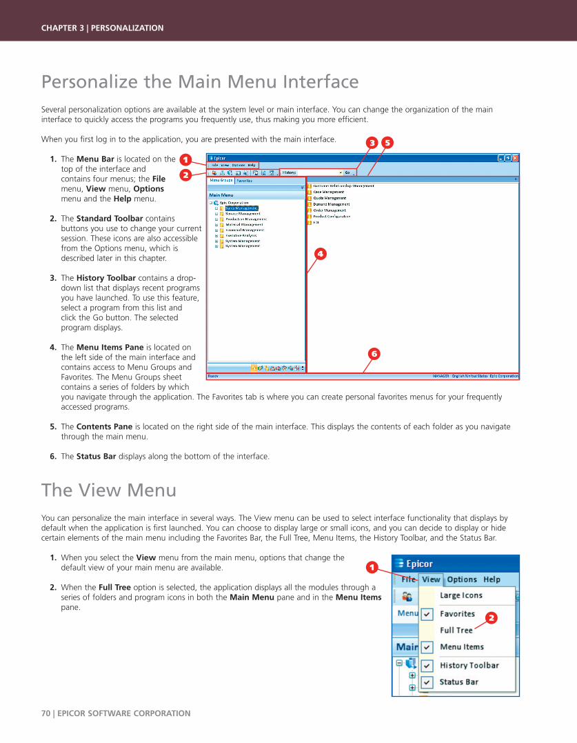
Personalize the Main Menu InterfaceSeveral personalization options are available at the system level or main interface. You can change the organization of the main interface to quickly access the programs you frequently use, thus making you more efficient.
When you first log in to the application, you are presented with the main interface.
1. The Menu Bar is located on the top of the interface and contains four menus; the File menu, View menu, Options menu and the Help menu.
2. The Standard Toolbar contains buttons you use to change your current session. These icons are also accessible from the Options menu, which is described later in this chapter.
3. The History Toolbar contains a drop-down list that displays recent programs you have launched. To use this feature, select a program from this list and click the Go button. The selected program displays.
4. The Menu Items Pane is located on the left side of the main interface and contains access to Menu Groups and Favorites. The Menu Groups sheet contains a series of folders by which you navigate through the application. The Favorites tab is where you can create personal favorites menus for your frequently accessed programs.
5. The Contents Pane is located on the right side of the main interface. This displays the contents of each folder as you navigate through the main menu.
6. The Status Bar displays along the bottom of the interface.
The View MenuYou can personalize the main interface in several ways. The View menu can be used to select interface functionality that displays bydefault when the application is first launched. You can choose to display large or small icons, and you can decide to display or hidecertain elements of the main menu including the Favorites Bar, the Full Tree, Menu Items, the History Toolbar, and the Status Bar.
1. When you select the View menu from the main menu, options that change the default view of your main menu are available.
2. When the Full Tree option is selected, the application displays all the modules through a series of folders and program icons in both the Main Menu pane and in the Menu Items pane.
CHAPTER 3 | PERSONALIZATION
70 | EPICOR SOFTWARE CORPORATION
1
6
4
2
53
1
2

3. The Main Menu pane is found on the left side of the main interface.
4. The Icon Level pane is found on the right side of the main interface.
5. When you select the Large Icons option from the View menu, theapplication displays folder contents aslarge icons in the Menu Items pane.
6. If you do not want to display the contents of the main menu folders in the Menu Items pane, you can deselect the Menu Items view. When you do this, you use the Full Tree to navigate to all folders and programs in the application.
7. When the History Toolbar is selected, a drop-down list displays on the main menu that contains programs that you have recently accessed.
PERSONALIZATION | CHAPTER 3
EPICOR SOFTWARE CORPORATION | 71
Throughout this user guide the FullTree and Menu Items views areused in all the menu displays.
6
4
7
5
3

8. When you select the Status Bar option from the View menu, the Status Bar displays at the bottom of the main interface. This bar contains information such as current company, location, language and other details about your current session.
The Options MenuThe Options menu contains settings you use to change your current company, plant, language, and so on. It also contains user preferences you leverage to personalize the Status Bar on your main interface. You can also save personalized settings automaticallywhen exiting the application.
The Options menu also contains access to the application’s Styling functionality which gives you complete control over the look and feel of theentire interface. You can use this toolset to display a pre-built design, or theme, from the options installed with the application.
The Preferences command controls specific elements that display on theStatus Bar of the main interface. You can also add a tab to the Main Menufor displaying dashboards and web sites.
Modify the Status Bar on the Main Interface
The Preferences command on the Options menu controls specific elements that display on your status bar of the main interface.
To modify the status bar on the main menu:
1. From the Options menu, select Preferences.
CHAPTER 3 | PERSONALIZATION
72 | EPICOR SOFTWARE CORPORATION
Additional options are available at the program level to modify the status bar for a particular program. Program Options are discussed laterin this chapter.
8
1

2. In the Preferences window, select the elements to display on the status bar. Notice you can place the current User ID, Language, Company, Plant, Server, and Workstation on the status bar.
3. You can click the Clear History button to remove the history from the History Toolbar.
4. Select the Tabs sheet to add a new tab to the main interface.
5. Click the New button to create a new tab that displays a Web Browser.
6. Enter the text you want to display on the tab in the Tab Caption field. In this example you enter Epicor.com.
7. Select Web Browser in the Type field. You can also select the Dashboard Type to display a system dashboard on the main menu.
8. Enter the web address you want to display in the Content field. If youhave chosen Dashboard in the Type field, the Content field contains a list ofDashboards in the application for you to select.
9. Click OK.
PERSONALIZATION | CHAPTER 3
EPICOR SOFTWARE CORPORATION | 73
86
4
2
9
75
3
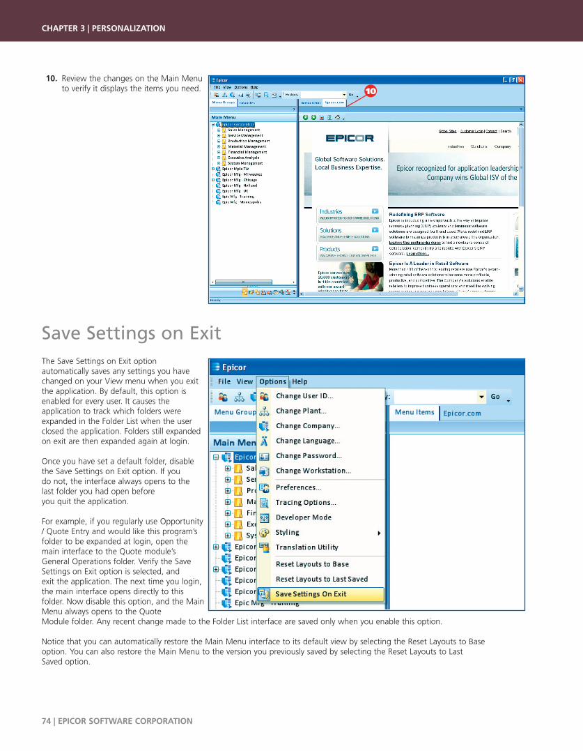
10. Review the changes on the Main Menu to verify it displays the items you need.
Save Settings on ExitThe Save Settings on Exit option automatically saves any settings you havechanged on your View menu when you exitthe application. By default, this option isenabled for every user. It causes theapplication to track which folders wereexpanded in the Folder List when the userclosed the application. Folders still expandedon exit are then expanded again at login.
Once you have set a default folder, disablethe Save Settings on Exit option. If you do not, the interface always opens to the last folder you had open before you quit the application.10For example, if you regularly use Opportunity/ Quote Entry and would like this program’sfolder to be expanded at login, open themain interface to the Quote module’s General Operations folder. Verify the SaveSettings on Exit option is selected, and exit the application. The next time you login,the main interface opens directly to this folder. Now disable this option, and the MainMenu always opens to the Quote Module folder. Any recent change made to the Folder List interface are saved only when you enable this option.
Notice that you can automatically restore the Main Menu interface to its default view by selecting the Reset Layouts to Base option. You can also restore the Main Menu to the version you previously saved by selecting the Reset Layouts to Last Saved option.
CHAPTER 3 | PERSONALIZATION
74 | EPICOR SOFTWARE CORPORATION
10
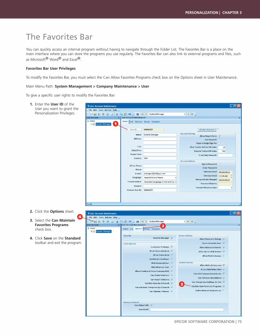
The Favorites BarYou can quickly access an internal program without having to navigate through the Folder List. The Favorites Bar is a place on themain interface where you can store the programs you use regularly. The Favorites Bar can also link to external programs and files, such
as Microsoft® Word® and Excel®.
Favorites Bar User Privileges
To modify the Favorites Bar, you must select the Can Allow Favorites Programs check box on the Options sheet in User Maintenance.
Main Menu Path: System Management > Company Maintenance > User
To give a specific user rights to modify the Favorites Bar:
1. Enter the User ID of the User you want to grant the Personalization Privileges.
2. Click the Options sheet.
3. Select the Can Maintain Favorites Programs check box.
4. Click Save on the Standardtoolbar and exit the program.
PERSONALIZATION | CHAPTER 3
EPICOR SOFTWARE CORPORATION | 75
1
4
2
3
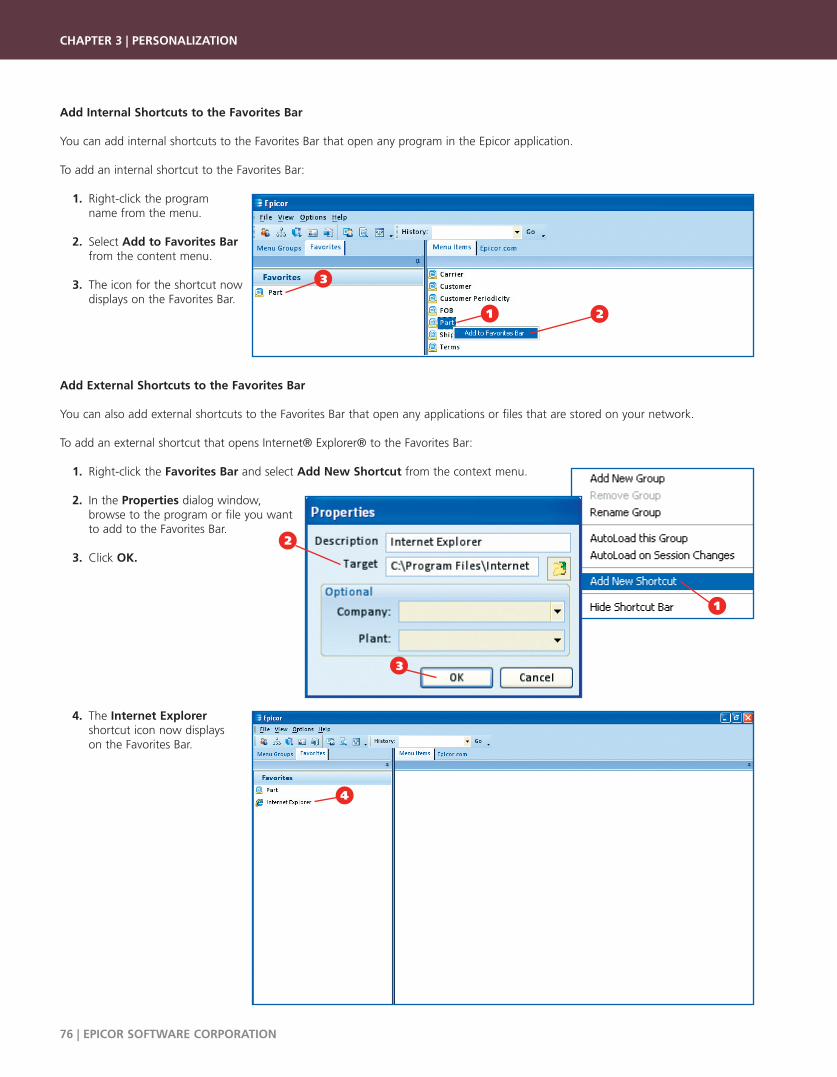
Add Internal Shortcuts to the Favorites Bar
You can add internal shortcuts to the Favorites Bar that open any program in the Epicor application.
To add an internal shortcut to the Favorites Bar:
1. Right-click the program name from the menu.
2. Select Add to Favorites Bar from the content menu.
3. The icon for the shortcut now displays on the Favorites Bar.
Add External Shortcuts to the Favorites Bar
You can also add external shortcuts to the Favorites Bar that open any applications or files that are stored on your network.
To add an external shortcut that opens Internet® Explorer® to the Favorites Bar:
1. Right-click the Favorites Bar and select Add New Shortcut from the context menu.
2. In the Properties dialog window, browse to the program or file you want to add to the Favorites Bar.
3. Click OK.
4. The Internet Explorer shortcut icon now displays on the Favorites Bar.
CHAPTER 3 | PERSONALIZATION
76 | EPICOR SOFTWARE CORPORATION
1 2
3
1
4
2
3
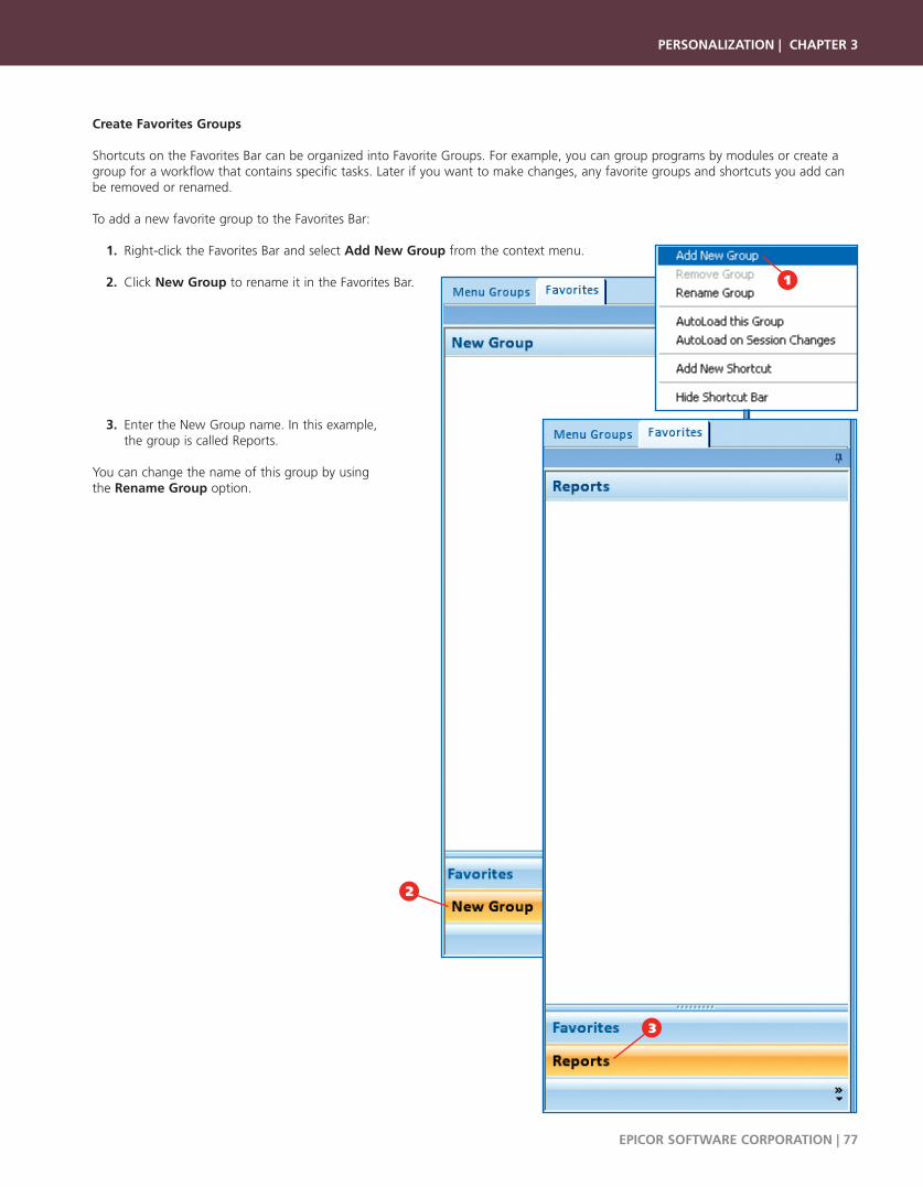
Create Favorites Groups
Shortcuts on the Favorites Bar can be organized into Favorite Groups. For example, you can group programs by modules or create agroup for a workflow that contains specific tasks. Later if you want to make changes, any favorite groups and shortcuts you add canbe removed or renamed.
To add a new favorite group to the Favorites Bar:
1. Right-click the Favorites Bar and select Add New Group from the context menu.
2. Click New Group to rename it in the Favorites Bar.
3. Enter the New Group name. In this example, the group is called Reports.
You can change the name of this group by using the Rename Group option.
PERSONALIZATION | CHAPTER 3
EPICOR SOFTWARE CORPORATION | 77
2
3
1

AutoLoad Favorites Groups
You can improve the performance of Favorites Bar programs you use the most by using the AutoLoad feature. This programautomatically loads selected programs in your workstation's memory. When you select an autoload option for a favorites group, all theprograms contained within the favorite group are temporarily selected for memory caching. Each program can then be pre-loaded intomemory during the current session so when you launch one of these selected programs, it displays faster.
To access the AutoLoad options, right-click a Favorites Group.
Two AutoLoad options are available on the Favorites Bar.
1. AutoLoad this Group - Automatically loads favorites group programs into your workstation’s memory when you log into the application.
2. AutoLoad on Session Changes - This option causes memory cached programs to re-load into memory when the User, Plant, Company, or Language are changed during the current session.
Memory Caching
When you select an Autoload option for a favorites group, all the programscontained within the favorite group automatically are selected for MemoryCaching. Each program can then be pre-loaded into memory. This improvesthe program’s performance in Run Mode, as it displays faster when you launch it again during the current session.
Before you personalize or customize a memory cached program, be sure you disable this feature. To do this, press the [Shift] key onthe keyboard and then launch the program. You can do this from either the Main Menu or a context menu.
1. After any program is launched (in this example the Part Maintenanceform has been launched), click the Tools menu.
2. Select Options.
CHAPTER 3 | PERSONALIZATION
78 | EPICOR SOFTWARE CORPORATION
The AutoLoad feature uses some of your system memory. You should not select everyprogram for AutoLoad, as this feature uses some of your system memory. When theAutoLoad option is enabled, the application takes longer for the login process. Whileprograms autoload, you can continue to do other things like answer email or webbrowsing. While the programs within the Favorites Group are loading in thebackground, an icon appears on your workstation’s system tray.
The Memory Cache option is located in the program’s Options window. The Memory Cachecheck box appears on the General tab. Additionalinformation on this option is reviewed in the Optionssection of this chapter.
2
1
1
2

3. The Options window displays.
4. On the General tab, clear the Memory Cache check box.
5. Click OK.
6. Exit the program.
Personalize the Program InterfaceThe program interface has many personalization features available. You can personalize each program’s interface so it displays theconfiguration that works best for you.
Personalization Options Window
Many of the program level personalization features are found in the Optionswindow from the Tools menu in a specific program. Once the options areselected from this window, they become the default standards that are usedeach time the program is run. In addition, this window has several global settings that affect every program.
In the following example, Customer Maintenance is used to demonstrate thepersonalization options.
Main Menu Path: Sales Management > Quote Management >Setup > Customer
1. Click the Tools menu.
2. Select Options.
PERSONALIZATION | CHAPTER 3
EPICOR SOFTWARE CORPORATION | 79
You can have the same program open multiple times. For example, one session of theprogram can have memory caching active, while another session of the program canturn off this function. You can then customize the program while its cached version isstill in use. To learn more about Customization, review Chapter 4: Basic Customization,Chapter 5: Advanced Customization, and Chapter 6: Customization Utilities.
6
4
5
3
1
2

General Options
The General tab contains options that affect the entire program. These options determine whether your sheet, toolbar, grid, and treeview personalizations save when you close the program. Special actions are also available, such as automatically launching the Searchwindow when you activate the program.
As The Form Opens - The options in1.this group cause specific actions tooccur as the program (form) launches.
No Action - When selected, this2.option causes the program (form)to launch normally. All theprogram’s fields are blank and youmust search for an existing recordor create a new record.
Auto Populate Data - When3.Auto Populate Data is selected, theprogram executes a search (the search form does not display) and selects all records to return themto the program.
Auto Load Search - When a program 4.is launched with this option enabled,the search form displays automaticallywithout having to click a button tomanually launch the search. If youspecify a named search (from the drop-down list) in conjunction with this Auto Load Search setting, the Named Search field in the search formpopulates with that search. When Auto Load Search is selected withoutspecifying a Named Search, the search form loads and waits for entry.
If you want to auto populate a program with many records, consider using aNamed Search to retrieve a filtered list of records instead of the whole table. A Named Search is search criteria previously defined and saved. This can beautomatically launched with the Auto Load Search option, or selectedmanually from the search window. Named Searches are discussed in greaterdetail within the Searches chapter in the Epicor ICE Tools User Guide.
Memory Cache - Select this option to cause the current program to stay in5.your computer’s memory after it closes. The next time you launch thisprogram, it appears faster, improving this program’s performance. Thisprogram only stays in memory during the current application session. Whenyou exit the application, the program is also removed from memory.
Only select this option for programs program you use most frequently. If thisoption is selected on several programs, your computer may run low on memory, impacting its performance.
Show Ribbon Override – Indicates whether the program toolbar displays as a ribbon instead of a series of drop-down menus.6.Select True to display the ribbon on the current program. The next section, Ribbon Interface, provides more detail about thisfeature.
On Save Layouts - The interface layouts of a program’s grids and sheets can be changed during a session. To save these7.changes for the next session, you would select the Save Layouts command from the Options menu of the main interface. Thetwo Save Layouts options found in a program’s Options dialog box control whether or not these changes are saved for a specificprogram. By default, these options are enabled in every program. Available options:
Save Dock Layouts: This option saves all the position changes you make to a program’s sheets. Personalizing sheet layouts is•discussed later in this chapter.
Save Grid Layouts: This option saves changes you make to a program’s grid layout. You can change the order in which•columns are displayed within each grid and also resize the grid’s column. Personalizing grid layouts is discussed later in thechapter.
CHAPTER 3 | PERSONALIZATION
80 | EPICOR SOFTWARE CORPORATION
The form takes longer to open when the autopopulate option is selected since the program isalso executing a search and loading everyrecord found in the data table. For example,using the Auto Populate option in Job Entry orPart Maintenance is not recommended. Thefiles in these programs tend to be very largewith many records. This can take a very longtime to launch the program.
You need to disable memory caching beforeyou can customize or personalize a program. Todisable memory caching, hold down the [Shift]key on the keyboard and then launch theprogram. This can be done from either themain interface or a context menu.
1
6
4
5
32 7
8
9
10
11

Context Menu - When selected, the Context Indicator check box causes the interface to show which fields have Context8.Menus. If the field has a context menu, a triangle displays in the upper right corner of the field. You can also personalize thecolor of the Context Indicator triangle by selecting a color from the drop-down list.
Select the Zone Indicator check box to define the color used for displaying any BAQ zone indicators on a program. Users hold9.their mouse over the BAQ zone indicator to display a tooltip of the BAQ results for the current value of the field (if any).Depending on the columns the BAQ returns, the BAQ zone can display different results. For example, you could have a BAQzone display the current customer’s web site.
For more information on creating business activity query zones, review Chapter 6: Customization Utilities. The BAQ Zones sectiondescribes how to create and display BAQ zones.
If you want to indicate which fields need data before a new record is saved, select the Required Field check box. 10.
Click OK. After you exit the Options window, notice all required fields become highlighted on the interface. Any sheet tabs that11.contain required fields are also highlighted.
When a field displays a Context Indicator, a context menu 12.can be accessed by right-clicking on the field. The field’scontext menu displays; you can use it to cut, copy, and pastetext as well as open related programs.
PERSONALIZATION | CHAPTER 3
EPICOR SOFTWARE CORPORATION | 81
12
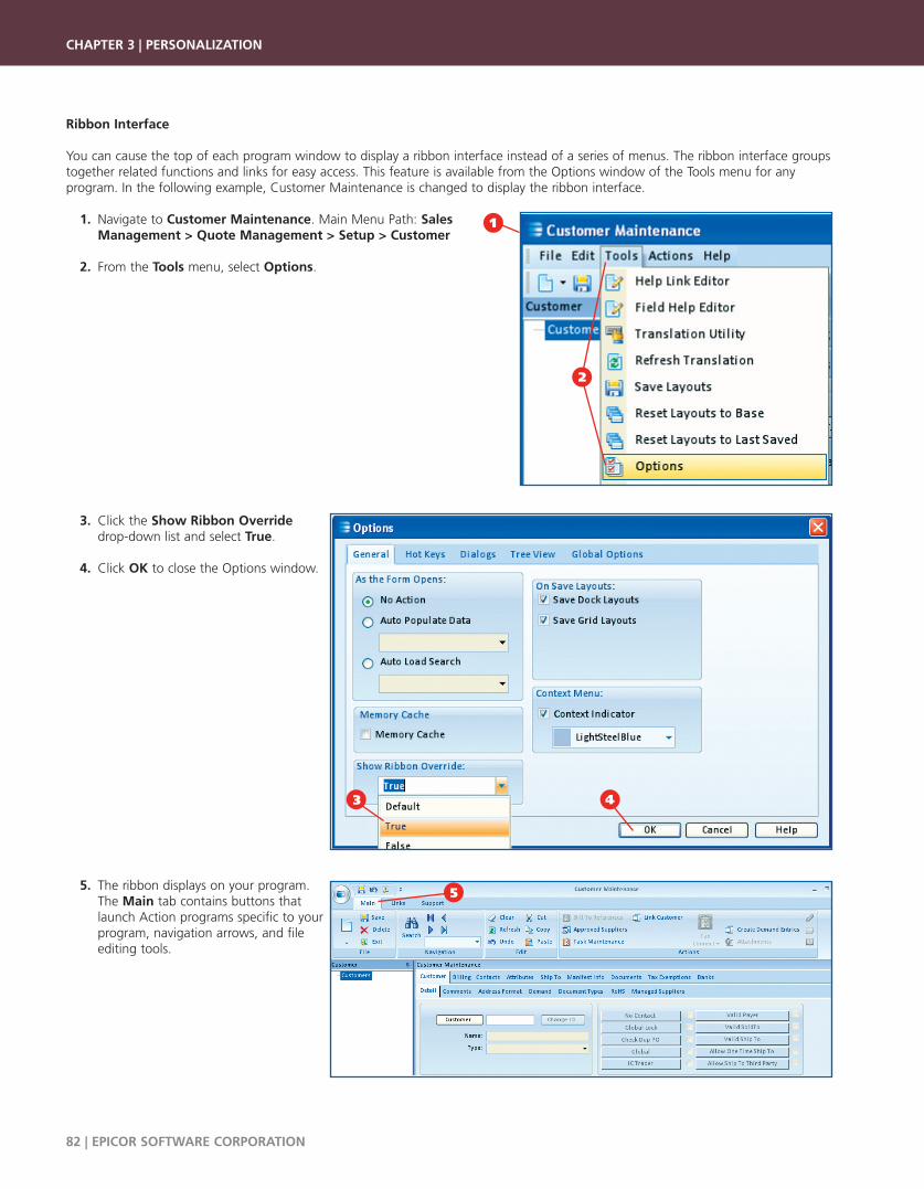
Ribbon Interface
You can cause the top of each program window to display a ribbon interface instead of a series of menus. The ribbon interface groupstogether related functions and links for easy access. This feature is available from the Options window of the Tools menu for anyprogram. In the following example, Customer Maintenance is changed to display the ribbon interface.
1. Navigate to Customer Maintenance. Main Menu Path: Sales Management > Quote Management > Setup > Customer
2. From the Tools menu, select Options.
3. Click the Show Ribbon Overridedrop-down list and select True.
4. Click OK to close the Options window.
5. The ribbon displays on your program. The Main tab contains buttons that launch Action programs specific to your program, navigation arrows, and file editing tools.
CHAPTER 3 | PERSONALIZATION
82 | EPICOR SOFTWARE CORPORATION
4
5
3
1
2

6. The Links tab contains buttons that launch programs related to the current program, like search and entry programs. It also contains the methods by which you can send the files created within the current program.
7. The Support tab contains buttons youuse to launch customization,personalization, and translation tools.You can also use this tab to access theapplication help and support resources available from Epicor.
8. To display the Save, Undo, and Exit buttons below the ribbon, select theShow Below the Ribbon option fromthe Quick Access toolbar. To place these buttons above the ribbon again, select the Show Above the Ribbon option from this toolbar.
9. To hide the ribbon from constantly displaying, select the Minimize the Ribbon option. The tabs still display, but the options do not appear unless you click the specific tab. To maximize the ribbon again, clear the Minimize the Ribbon option.
Hot Keys Options
Use Hot Keys (shortcut keys) to quickly navigate through the interface with keyboard options. The Hot Keys sheet is where all shortcut key combinations are defined for the current program. This sheet also contains controls you use to globally define specificfunctions. Global Options are discussed later in this chapter.
To define a Form Hot Key:
Select a Command from the drop-1.down list. Available options includeNew, Edit, Delete, and so on.
Click the Short Cut drop-down list and2.select the keyboard combination youwant to use for the command.Available options include <F4>,<Shift><F2>, <Alt> 5, and so on.
These shortcut key combinations are thenused on the current form.
PERSONALIZATION | CHAPTER 3
EPICOR SOFTWARE CORPORATION | 83
6
8
9
7
1
2
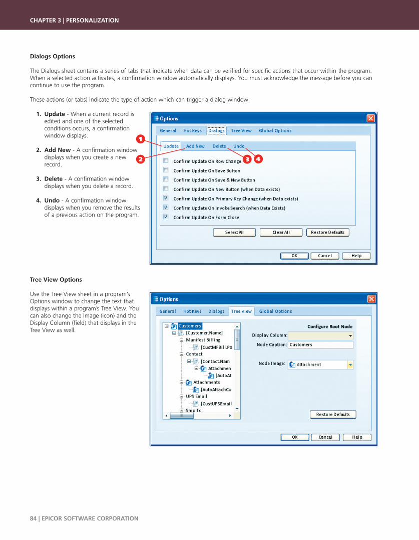
Dialogs Options
The Dialogs sheet contains a series of tabs that indicate when data can be verified for specific actions that occur within the program.When a selected action activates, a confirmation window automatically displays. You must acknowledge the message before you cancontinue to use the program.
These actions (or tabs) indicate the type of action which can trigger a dialog window:
1. Update - When a current record is edited and one of the selected conditions occurs, a confirmation window displays.
2. Add New - A confirmation window displays when you create a new record.
3. Delete - A confirmation window displays when you delete a record.
4. Undo - A confirmation window displays when you remove the results of a previous action on the program.
Tree View Options
Use the Tree View sheet in a program’sOptions window to change the text that displays within a program’s Tree View. Youcan also change the Image (icon) and theDisplay Column (field) that displays in the Tree View as well.
CHAPTER 3 | PERSONALIZATION
84 | EPICOR SOFTWARE CORPORATION
1
42 3

Global Options - Status Bar
Use the Global Options sheet to personalize global Hot Keys and modify the Status Bars that display in every program.
1. Select the Status Bar Panel options you want to display on programs. These options can be different from the status bar options that display on the Main Menu.
2. Click the Border Style and Panel Border Style drop-down lists to personalize these items on the interface.
Global Options - Hot Keys
You can define shortcut keys used throughout the application on the Hot Keys tab. In addition to defining shortcuts, several additionalglobal options are also available:
Select a Command from the drop-1.down list. Available options includeNew, Edit, Delete, and other programcommands.
Click the Short Cut drop-down list and2.select the keyboard combination youwant to use for the command.Available options include <F4>,<Shift><F2>, <Alt> 5, and so on. Thisshort cut key combination is then usedto launch this program functionthroughout the Epicor application.
Handle [Enter] as Tab - Select this3.check box to indicate you want to usethe Enter key to move through eachprogram's fields. You can then useboth the Tab and Enter keys to movethrough the fields.
Launch Search with - Define the4.global shortcut you want to use tolaunch a search from a selected field.
Launch Enterprise Search with – Use this shortcut combination to launch the Enterprise Search functionality. This search5.application retrieves indexed content from your Epicor application. You can search on any record within the Epicor database –like a part, customer, purchase order, AR invoice, and so on. For more information on Enterprise Search, review the Searcheschapter in the Epicor ICE Tools User Guide.
Launch Maintenance with – Use this drop-down list to define the shortcut used to launch the maintenance program for a6.selected field.
PERSONALIZATION | CHAPTER 3
EPICOR SOFTWARE CORPORATION | 85
2
1
1
3
2
6
4
5
7

Launch Info Zone with – A shortcut combination you use to activate a BAQ zone. Pressing this keyboard combination causes a7.tooltip to display BAQ results for the current value of the field (if any). Depending on the columns the BAQ returns, the BAQzone can display different results. For example, you could have a BAQ zone display the current customer’s web site.
For more information on creating business activity query zones, review Chapter 6: Customization Utilities. The BAQ Zones sectiondescribes how to create and display BAQ zones.
Use the Designer Grid tab to specify8.the grid characteristics used when youare in personalization mode. Gridsettings include activating the Snap ToGrid functionality, and determining thegrid size.
The Snap to Grid option helps9.position elements when you arecreating personalizations on a grid.When this option is selected, theshapes pull, or snap, towards the griddots.
For example, if Snap To Grid is selectedand you add a check box to the form,the box snaps towards the nearest griddots, instead of floating between thedots.
Use the Grid Width and Grid Height10.values to specify the space, in pixels,that displays between the grid dots inPersonalization mode.
Click OK to save your changes and exit the Options dialog window.11.
Personalize Sheet LayoutsA sheet is a layer of a program’s interface that contains related functionality. Every program contains at least two or more sheets (theDetail and the List sheet). You can use the personalization tools to change the position of any sheet within a program. By clicking anddragging each sheet’s tab, you can also change the order in which the sheets are displayed. A sheet can even be completely movedout of the program so that it displays as a floating sheet.
Modify Sheet Tab Order
Each sheet displays with a tab. The order of the tabs within a sheet can be changed by clicking and dragging the tab to a new position.
For example, in Part Class Maintenance displayed below, the Detail sheet displays to the left of the List sheet by default. By clicking and dragging the List tab, you can move it to the left side of the Detail sheet:
1. Before the List sheet is moved.
CHAPTER 3 | PERSONALIZATION
86 | EPICOR SOFTWARE CORPORATION
10
8
11
9
1
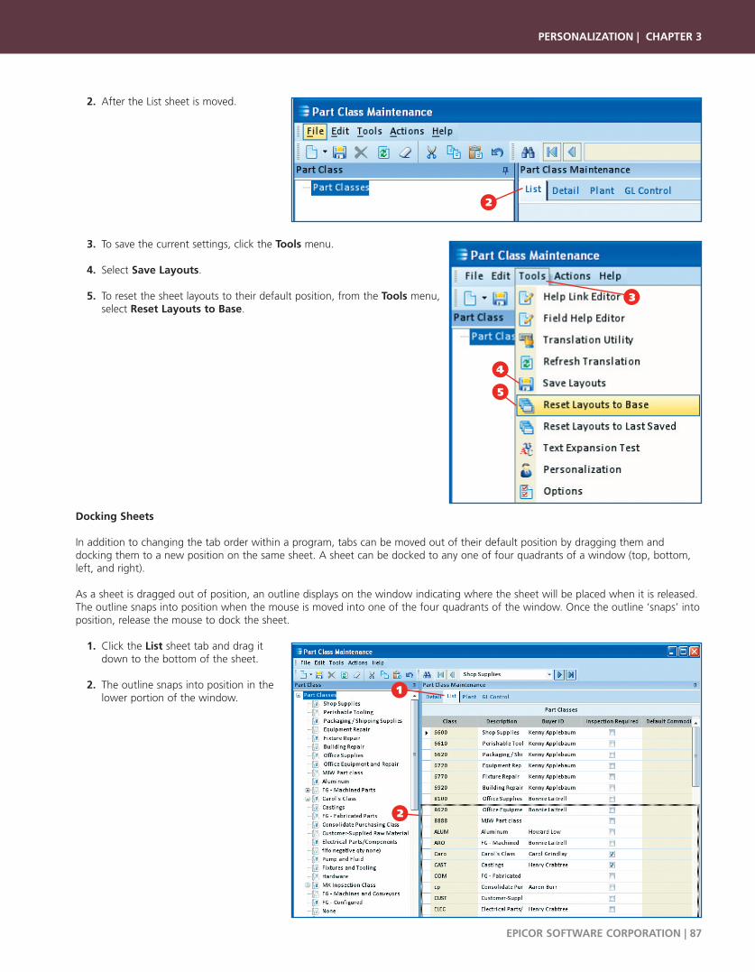
2. After the List sheet is moved.
3. To save the current settings, click the Tools menu.
4. Select Save Layouts.
5. To reset the sheet layouts to their default position, from the Tools menu, select Reset Layouts to Base.
Docking Sheets
In addition to changing the tab order within a program, tabs can be moved out of their default position by dragging them and docking them to a new position on the same sheet. A sheet can be docked to any one of four quadrants of a window (top, bottom,left, and right).
As a sheet is dragged out of position, an outline displays on the window indicating where the sheet will be placed when it is released.The outline snaps into position when the mouse is moved into one of the four quadrants of the window. Once the outline ‘snaps’ intoposition, release the mouse to dock the sheet.
1. Click the List sheet tab and drag it down to the bottom of the sheet.
2. The outline snaps into position in the lower portion of the window.
PERSONALIZATION | CHAPTER 3
EPICOR SOFTWARE CORPORATION | 87
4
2
3
5
1
2
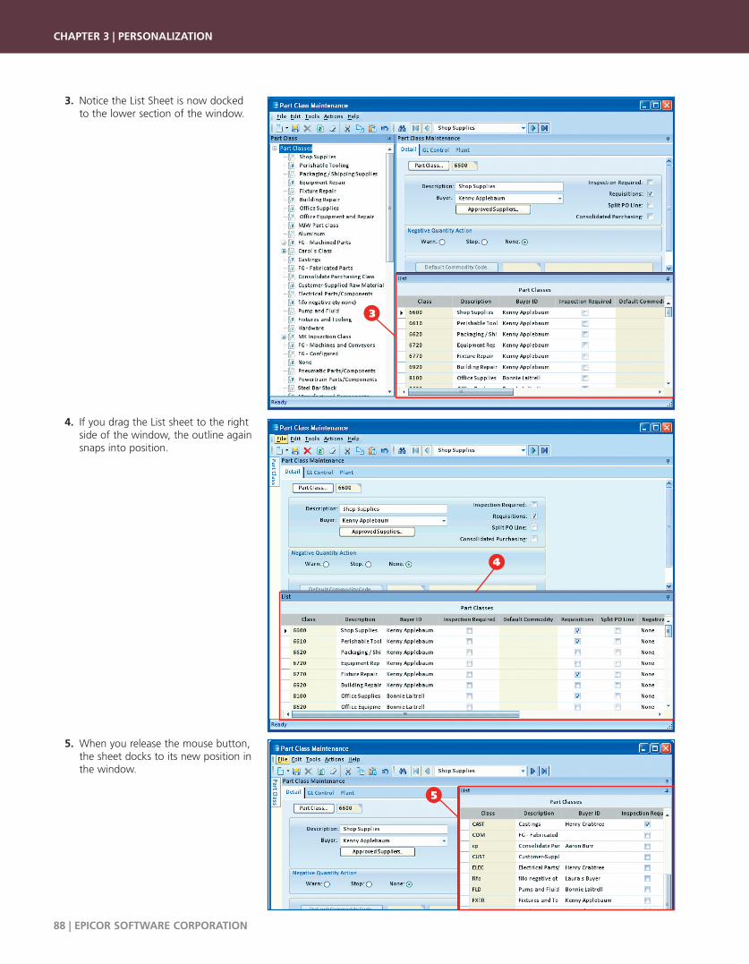
3. Notice the List Sheet is now docked to the lower section of the window.
4. If you drag the List sheet to the right side of the window, the outline again snaps into position.
5. When you release the mouse button, the sheet docks to its new position in the window.
CHAPTER 3 | PERSONALIZATION
88 | EPICOR SOFTWARE CORPORATION
5
3
4
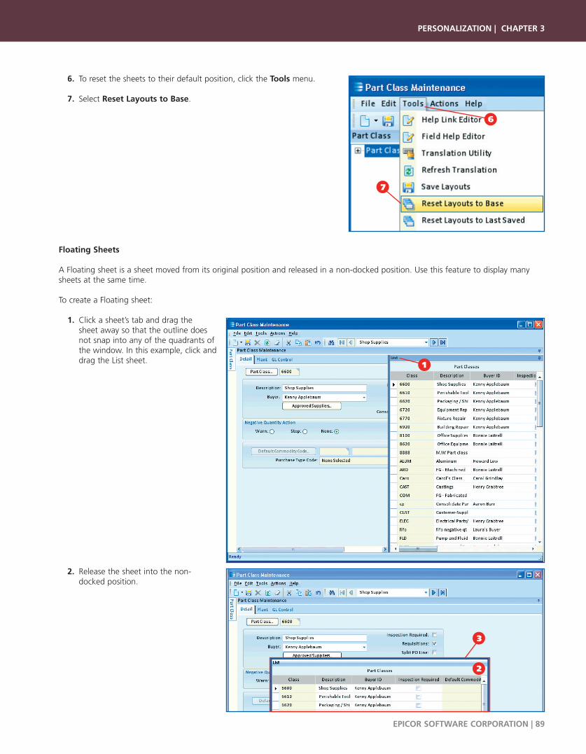
6. To reset the sheets to their default position, click the Tools menu.
7. Select Reset Layouts to Base.
Floating Sheets
A Floating sheet is a sheet moved from its original position and released in a non-docked position. Use this feature to display manysheets at the same time.
To create a Floating sheet:
1. Click a sheet’s tab and drag the sheet away so that the outline does not snap into any of the quadrants of the window. In this example, click and drag the List sheet.
2. Release the sheet into the non-docked position.
PERSONALIZATION | CHAPTER 3
EPICOR SOFTWARE CORPORATION | 89
6
7
1
2
3
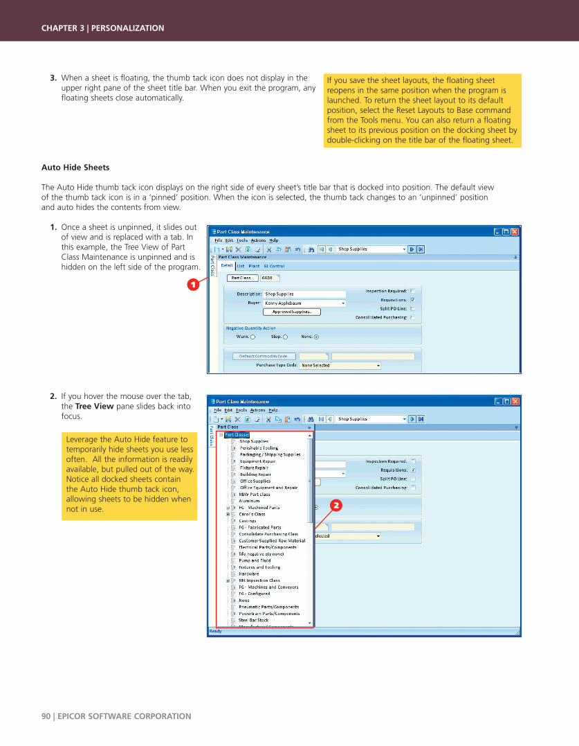
3. When a sheet is floating, the thumb tack icon does not display in theupper right pane of the sheet title bar. When you exit the program, any floating sheets close automatically.
Auto Hide Sheets
The Auto Hide thumb tack icon displays on the right side of every sheet’s title bar that is docked into position. The default view of the thumb tack icon is in a ‘pinned’ position. When the icon is selected, the thumb tack changes to an ‘unpinned’ position and auto hides the contents from view.
1. Once a sheet is unpinned, it slides out of view and is replaced with a tab. In this example, the Tree View of Part Class Maintenance is unpinned and is hidden on the left side of the program.
2. If you hover the mouse over the tab, the Tree View pane slides back into focus.
CHAPTER 3 | PERSONALIZATION
90 | EPICOR SOFTWARE CORPORATION
If you save the sheet layouts, the floating sheetreopens in the same position when the program islaunched. To return the sheet layout to its defaultposition, select the Reset Layouts to Base commandfrom the Tools menu. You can also return a floatingsheet to its previous position on the docking sheet bydouble-clicking on the title bar of the floating sheet.
Leverage the Auto Hide feature totemporarily hide sheets you use lessoften. All the information is readilyavailable, but pulled out of the way.Notice all docked sheets containthe Auto Hide thumb tack icon,allowing sheets to be hidden whennot in use.
1
2
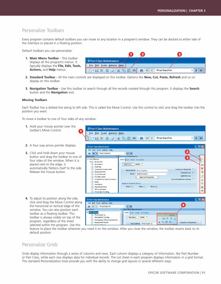
Personalize Toolbars
Every program contains default toolbars you can move to any location in a program’s window. They can be docked to either side ofthe interface or placed in a floating position.
Default toolbars you can personalize:
1. Main Menu Toolbar - This toolbar displays all the program’s menus. It typically displays the File, Edit, Tools,Actions, and Help menus.
2. Standard Toolbar - All the main controls are displayed on this toolbar. Options like New, Cut, Paste, Refresh and so on display on this toolbar.
3. Navigation Toolbar - Use this toolbar to search through all the records created through this program. It displays the Search button and the Navigation tool.
Moving Toolbars
Each Toolbar has a dotted line along its left side. This is called the Move Control. Use this control to click and drag the toolbar into theposition you want.
To move a toolbar to one of four sides of any window:
1. Hold your mouse pointer over the toolbar’s Move Control.
2. A four way arrow pointer displays.
3. Click and hold down your mouse button and drag the toolbar to one of four sides of the window. When it is placed next to the edge, it automatically flattens itself to the side. Release the mouse button.
4. To adjust its position along the side, click and drag the Move Control along the horizontal or vertical edge of the window. You can also position each toolbar as a floating toolbar. This toolbar is always visible on top of the program, regardless of the sheet selected within the program. Use this feature to place the toolbar wherever you need it on the window. After you close the window, the toolbar reverts back to its default position.
Personalize Grids
Grids display information through a series of columns and rows. Each column displays a category of information, like Part Number or Part Class, while each row displays data for individual records. The List sheet in each program displays information in a grid format.The standard Personalization tools provide you with the ability to change grid layouts in several different ways.
PERSONALIZATION | CHAPTER 3
EPICOR SOFTWARE CORPORATION | 91
1 2 3
1
4
2
3

Additional personalization options are available to users who have the Personalization privilege enabled in their User ID. These optionsare reviewed in the Personalization Mode section of this chapter.
Change Column Order
Every grid’s columns can be moved around into any order that you want.
1. To move a column within a grid, click and drag the column to the desired position.
2. When the red arrows display, release the mouse button and the column docks in its new position.
3. In the example below, the Buyer ID column is moved to the far left.
Adjust Column Width
You can also adjust the column width so the maximum amount of information displays in each column.
To automatically adjust the width of a column to fit the data it contains:
1. Place the mouse pointer over the right edge of a column header. The mouse pointer turns into a double arrow icon.
2. Double-click the mouse to adjust the width of the column to auto-fit its contents.
CHAPTER 3 | PERSONALIZATION
92 | EPICOR SOFTWARE CORPORATION
1
3
2
To manually adjust the width of a column, place themouse pointer over the edge of a column. Themouse pointer turns into a double arrow icon. Clickand drag the arrow to the left or the right to widenor shrink the column manually.
1

Grid Split Option
1. Available on the left of horizontal scrollbars and on the top of vertical scrollbars of each grid is a small bar that can be dragged to split a grid either vertically or horizontally.
2. Similar to the freeze panes option in a spreadsheet, when you place the mouse over the bar it changes to a double arrow icon.
3. You can drag this bar towards the center of the grid to split it.
Sort Columns
You can sort the grid records in ascending or descending order using the data in a selected column (field). To sort columns:
1. Click the column header by which you would like to sort.
The grid automatically sorts the contents in ascending order based on the selected column.
2. When you sort by a particular column, an arrow icon displays in the column header indicating an ascending sort. In this example, the Part Class records that contain a blank Buyer ID sorts at the top of the list. You can then identify records you need to update.
3. You can change the sort on a column to be descending by clicking the column header again.
4. Notice the arrow icon now displays upside down. This indicates the grid is sorted in descending order by the data in this column.
PERSONALIZATION | CHAPTER 3
EPICOR SOFTWARE CORPORATION | 93
1
2
3
1
4
2
3
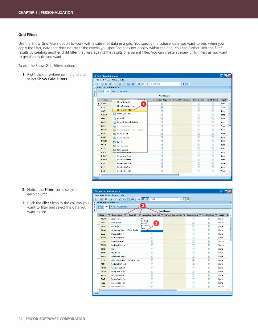
Grid Filters
Use the Show Grid Filters option to work with a subset of data in a grid. You specify the column data you want to see; when youapply the filter, data that does not meet the criteria you specified does not display within the grid. You can further limit the filterresults by creating another child filter that runs against the results of a parent filter. You can create as many child filters as you wantto get the results you want.
To use the Show Grid Filters option:
1. Right-click anywhere on the grid and select Show Grid Filters.
2. Notice the Filter icon displays in each column.
3. Click the Filter icon in the column you want to filter and select the data you want to see.
CHAPTER 3 | PERSONALIZATION
94 | EPICOR SOFTWARE CORPORATION
1
2
3

4. The grid now displays only rows that contain the column data you filtered. Notice the Filter icon changes to indicate a grid filter has been applied to the data in the grid.
Show Group By
Many grids offer Show Group By functionality that groups all of the records in a grid by a specific column. This option is available inany grid, and especially useful in the Dashboard programs.
The Sales Order Backlog Status dashboard is used to illustrate this functionality.
1. Navigate to the Sales Order Backlog Statusdashboard. Main Menu Path: Executive Analysis > Status Dashboards > Sales Order Backlog Status
2. Click the Refresh All button to retrieve all the part records to the dashboard.
PERSONALIZATION | CHAPTER 3
EPICOR SOFTWARE CORPORATION | 95
2
1
4
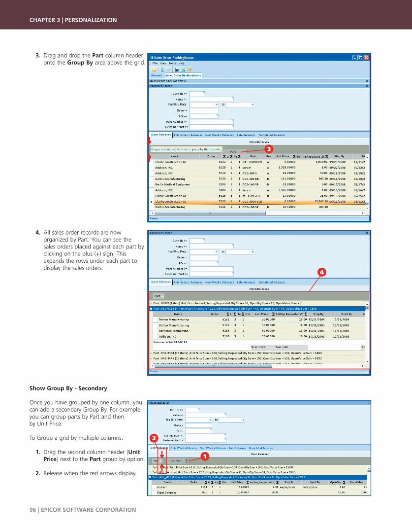
3. Drag and drop the Part column header onto the Group By area above the grid.
4. All sales order records are now organized by Part. You can see the sales orders placed against each part by clicking on the plus (+) sign. This expands the rows under each part to display the sales orders.
Show Group By - Secondary
Once you have grouped by one column, youcan add a secondary Group By. For example,you can group parts by Part and then by Unit Price.
To Group a grid by multiple columns:
1. Drag the second column header (Unit Price) next to the Part group by option.
2. Release when the red arrows display.
CHAPTER 3 | PERSONALIZATION
96 | EPICOR SOFTWARE CORPORATION
4
1
2
3
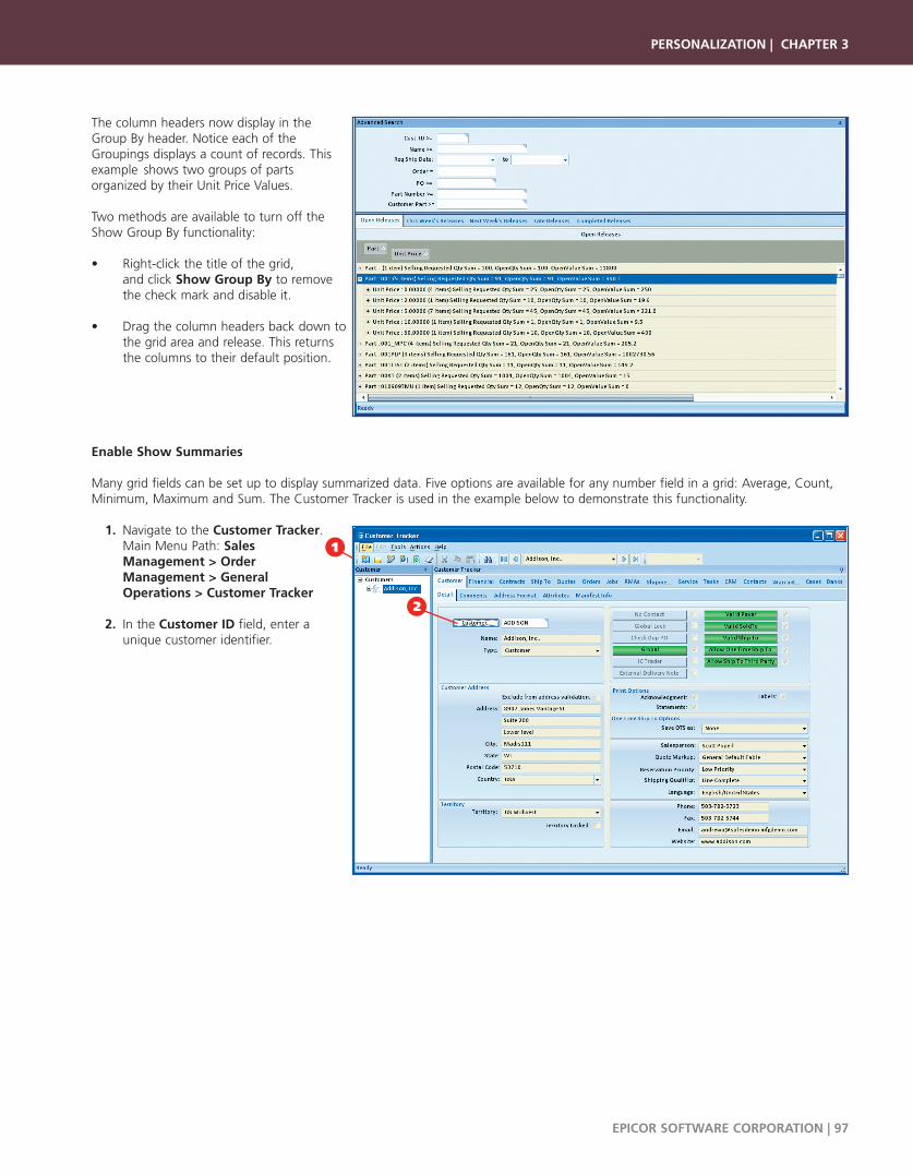
The column headers now display in the Group By header. Notice each of theGroupings displays a count of records. Thisexample shows two groups of parts organized by their Unit Price Values.
Two methods are available to turn off theShow Group By functionality:
• Right-click the title of the grid, and click Show Group By to remove the check mark and disable it.
• Drag the column headers back down to the grid area and release. This returns the columns to their default position.
Enable Show Summaries
Many grid fields can be set up to display summarized data. Five options are available for any number field in a grid: Average, Count,Minimum, Maximum and Sum. The Customer Tracker is used in the example below to demonstrate this functionality.
1. Navigate to the Customer Tracker. Main Menu Path: Sales Management > Order Management > General Operations > Customer Tracker
2. In the Customer ID field, enter a unique customer identifier.
PERSONALIZATION | CHAPTER 3
EPICOR SOFTWARE CORPORATION | 97
2
1

3. Select the Orders sheet and click the Retrieve button to display all the open orders for the customer.
4. Right-click the Open Orders title of the grid.
5. Select Show Summaries.
6. Once the option is enabled, the column header for every number field in the grid will display a Sigma icon. To access the Summary options for a specific field, click the Sigma icon next to the column header.
7. Select any or all of the options that display in the Select Summaries window.
8. When selected, the Sum option totals the column and adds Grand Summaryinformation along the bottom of the grid.
CHAPTER 3 | PERSONALIZATION
98 | EPICOR SOFTWARE CORPORATION
7
8
5
43
6
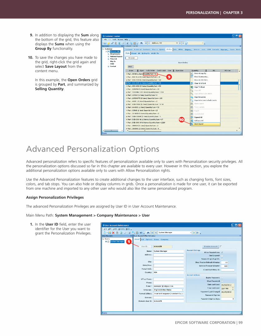
9. In addition to displaying the Sum along the bottom of the grid, this feature also displays the Sums when using the Group By functionality.
10. To save the changes you have made to the grid, right-click the grid again and select Save Layout from the content menu.
In this example, the Open Orders grid is grouped by Part, and summarized by Selling Quantity.
Advanced Personalization OptionsAdvanced personalization refers to specific features of personalization available only to users with Personalization security privileges. Allthe personalization options discussed so far in this chapter are available to every user. However in this section, you explore theadditional personalization options available only to users with Allow Personalization rights.
Use the Advanced Personalization features to create additional changes to the user interface, such as changing fonts, font sizes, colors, and tab stops. You can also hide or display columns in grids. Once a personalization is made for one user, it can be exportedfrom one machine and imported to any other user who would also like the same personalized program.
Assign Personalization Privileges
The advanced Personalization Privileges are assigned by User ID in User Account Maintenance.
Main Menu Path: System Management > Company Maintenance > User
1. In the User ID field, enter the user identifier for the User you want to grant the Personalization Privileges.
PERSONALIZATION | CHAPTER 3
EPICOR SOFTWARE CORPORATION | 99
9
10
1

2. Click the Options sheet.
3. Select the Allow Personalization check box.
4. Click Save and exit the program.
Activate Personalization Mode
To access the Advanced Personalization features, select Personalization from the Tools menu in any program. In this example, you arepersonalizing the interface for Sales Order Entry. After you launch the program, you must activate personalization mode to begin personalizing this program.
1. Navigate to Sales Order Entry. Main Menu Path: Sales Management > Order Management > General Operations > Order Entry
2. From the Tools menu, select Personalization.
3. This opens the Control Properties window for that program.
The Control Properties window contains all the advanced personalization features. This window displays in the forefront of your window until it is closed by selecting the Delete, OK, or Cancel buttons.
4. A grid also displays over the sheet currently in focus. Use this grid to help you move elements to the areas where you want them.
CHAPTER 3 | PERSONALIZATION
100 | EPICOR SOFTWARE CORPORATION
4
3
1
2
4
2
3
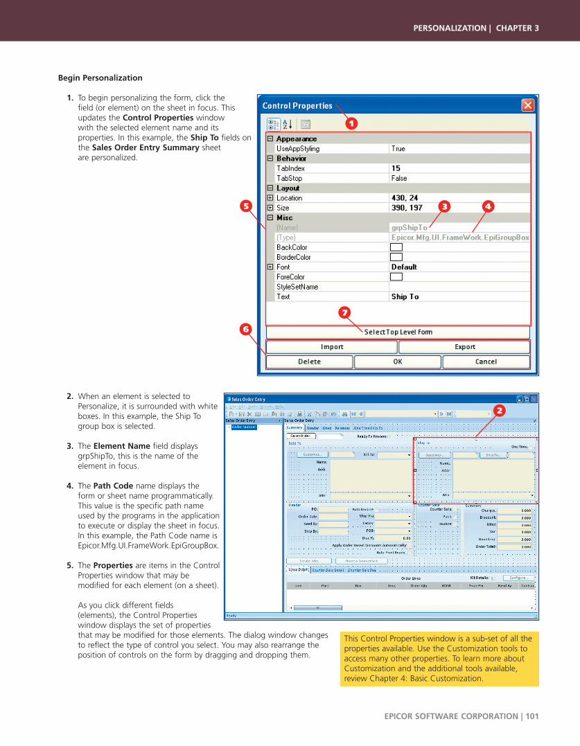
Begin Personalization
1. To begin personalizing the form, click the field (or element) on the sheet in focus. This updates the Control Properties window with the selected element name and its properties. In this example, the Ship To fields on the Sales Order Entry Summary sheet are personalized.
2. When an element is selected toPersonalize, it is surrounded with whiteboxes. In this example, the Ship Togroup box is selected.
3. The Element Name field displays grpShipTo, this is the name of the element in focus.
4. The Path Code name displays the form or sheet name programmatically. This value is the specific path name used by the programs in the application to execute or display the sheet in focus. In this example, the Path Code name is Epicor.Mfg.UI.FrameWork.EpiGroupBox.
5. The Properties are items in the Control Properties window that may be modified for each element (on a sheet).
As you click different fields (elements), the Control Properties window displays the set of properties that may be modified for those elements. The dialog window changes to reflect the type of control you select. You may also rearrange the position of controls on the form by dragging and dropping them.
PERSONALIZATION | CHAPTER 3
EPICOR SOFTWARE CORPORATION | 101
1
5 3 4
6
7
2
This Control Properties window is a sub-set of all theproperties available. Use the Customization tools toaccess many other properties. To learn more aboutCustomization and the additional tools available,review Chapter 4: Basic Customization.
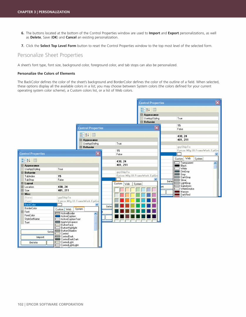
6. The buttons located at the bottom of the Control Properties window are used to Import and Export personalizations, as well as Delete, Save (OK) and Cancel an existing personalization.
7. Click the Select Top Level Form button to reset the Control Properties window to the top most level of the selected form.
Personalize Sheet Properties
A sheet’s font type, font size, background color, foreground color, and tab stops can also be personalized.
Personalize the Colors of Elements
The BackColor defines the color of the sheet’s background and BorderColor defines the color of the outline of a field. When selected,these options display all the available colors in a list; you may choose between System colors (the colors defined for your current operating system color scheme), a Custom colors list, or a list of Web colors.
CHAPTER 3 | PERSONALIZATION
102 | EPICOR SOFTWARE CORPORATION

1. Select the Ship To group box.
2. In the Control Properties window, click the BorderColor property. A drop-down list of colors to choose from displays.
3. Select the Custom color tab and choose a color to apply to the border of the group box.
4. Notice the group box border changes color.
5. Click OK (not pictured) to save your changes.
Change the Font Type and Foreground Color
You can also personalize the Font Type and the Font Color (Fore Color) of text. Here’s how:
1. Select the Name label inside the Ship To group box.
PERSONALIZATION | CHAPTER 3
EPICOR SOFTWARE CORPORATION | 103
1
1
3
4
2
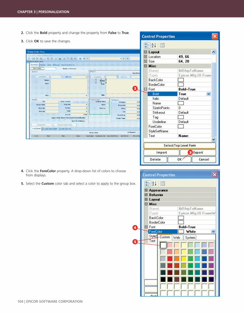
2. Click the Bold property and change the property from False to True.
3. Click OK to save the changes.
4. Click the ForeColor property. A drop-down list of colors to choose from displays.
5. Select the Custom color tab and select a color to apply to the group box.
CHAPTER 3 | PERSONALIZATION
104 | EPICOR SOFTWARE CORPORATION
4
5
2
3

6. Click OK to save the changes.
Change the Location and Size
The Location property refers to the exact position of the control (or element) on the sheet. The location is defined as X and Y axisnumbers. You can expand the property to change the X and Y axis or you can click and drag the element to a new position on thesheet. The Location property updates with the new X and Y axis points.
In the example below, the Attention field is moved from below the Name and Address field to above the Name and Address field, next to the Ship To ID field.
1. Before the Attn field is moved.
PERSONALIZATION | CHAPTER 3
EPICOR SOFTWARE CORPORATION | 105
6
1
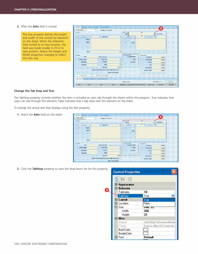
2. After the Attn field is moved.
Change the Tab Stop and Text
The TabStop property controls whether the item is included as users tab through the sheets within this program. True indicates thatusers can tab through this element; False indicates that a tab skips over this element on the sheet.
To change the actual text that displays using the Text property:
1. Select the Attn field on the sheet.
2. Click the TabStop property to view the drop-down list for this property.
CHAPTER 3 | PERSONALIZATION
106 | EPICOR SOFTWARE CORPORATION
The Size property defines the heightand width of the control (or element)on the sheet. When the Attentionfield moved to its new location, thefield was made smaller to fit in itsnew position. Notice the Height andWidth properties changed to reflectthis new size.
2
1
2

3. Change the property from True to False.
4. Click the Addr: label on the window.
PERSONALIZATION | CHAPTER 3
EPICOR SOFTWARE CORPORATION | 107
While the screen captures in this guide cannot display the immediate change, know that now when you tab through theprompts on this window, you skip this field.
3
4

5. In the Text property, enter Address.
6. Click OK to save the changes.
Modify Grid PropertiesGrids display information through a series of columns and rows. Using the Control Properties window, you have the ability to hidefields (columns) so they do not display in a grid. To access grid options, click a grid within a sheet. The Control Properties window expands to display grid Column Properties. You can then determine the columns to hide or display by selecting the appropriate check boxes.
Hide Columns in a Grid
To hide columns in the Sales Order Entry, Lines Detail grid:
1. From the Tools menu, select Personalization.
CHAPTER 3 | PERSONALIZATION
108 | EPICOR SOFTWARE CORPORATION
1
6
5

2. The Control Properties window displays.
3. Click the Order Lines grid header on the Sales Order Entry summary sheet, Lines Detail tab.
4. Click the Column Properties drop-down list to display the Column Properties window.
5. Select which columns to Display or Hide by enabling (or disabling) the Hidden check box for each field (column).
6. You can also select the Toggle Hidden button to hide all columns. Click this button again to display them.
7. Click OK to save the changes.
8. The columns you want visible (their Hidden check boxes were not selected) now display on the Order Lines grid.
PERSONALIZATION | CHAPTER 3
EPICOR SOFTWARE CORPORATION | 109
7
54
2
6
83

Import, Export, and Delete PersonalizationsOnce you have created and saved a personalization, you can export it to other users. These users can then import this personalizationinto their environments. To do this, login as a different user, import the personalization to a new computer and it is then applied tothe current user account. If you decide you do not like some personalizations, you can also delete them.
Export a Personalization
1. After saving a personalization, in the Control Properties window, click the Export button.
2. The Save As window displays.
3. The default save location is a folder called Export on your local machine.
4. The File name is the application name followed by an underscore and the user name who is currently logged into the application. For example, after personalizing the Sales Order form logged in as system manager, the export filename defaults to App.SalesOrderEntry.SalesOrderForm_MANAGER.xml in the Export folder.
5. The Save As Type is an XML file type.
6. Click Save.1
CHAPTER 3 | PERSONALIZATION
110 | EPICOR SOFTWARE CORPORATION
1
6
2
5
3
4
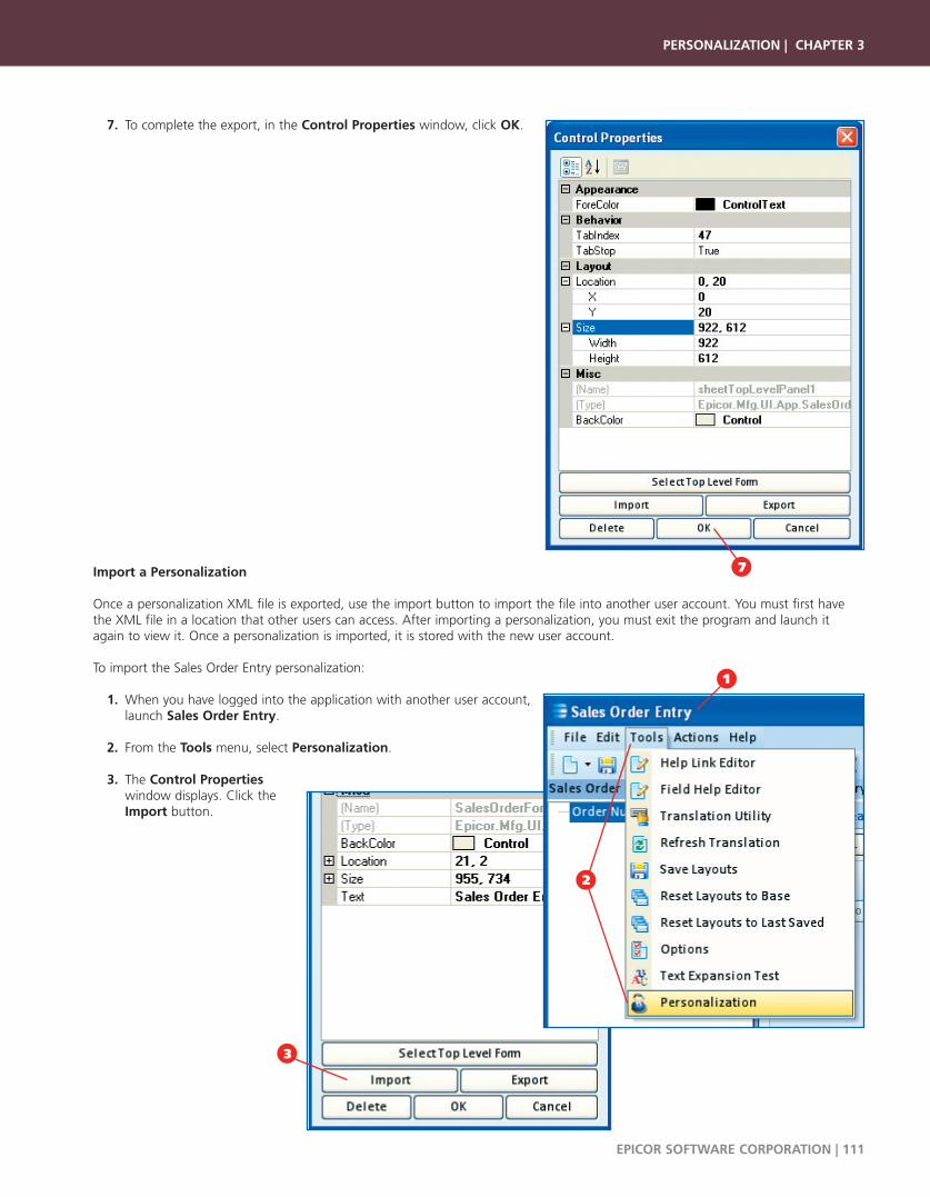
7. To complete the export, in the Control Properties window, click OK.
Import a Personalization
Once a personalization XML file is exported, use the import button to import the file into another user account. You must first havethe XML file in a location that other users can access. After importing a personalization, you must exit the program and launch itagain to view it. Once a personalization is imported, it is stored with the new user account.
To import the Sales Order Entry personalization:
1. When you have logged into the application with another user account, launch Sales Order Entry.
2. From the Tools menu, select Personalization.
3. The Control Properties window displays. Click the Import button.
PERSONALIZATION | CHAPTER 3
EPICOR SOFTWARE CORPORATION | 111
7
1
2
3
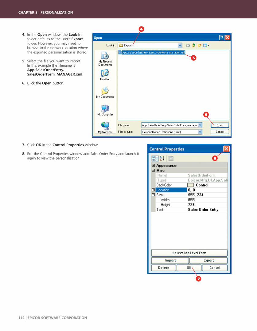
4. In the Open window, the Look In folder defaults to the user’s Export folder. However, you may need tobrowse to the network location wherethe exported personalization is stored.
5. Select the file you want to import. In this example the filename is App.SalesOrderEntry.SalesOrderForm_MANAGER.xml.
6. Click the Open button.
7. Click OK in the Control Properties window.
8. Exit the Control Properties window and Sales Order Entry and launch it again to view the personalization.
CHAPTER 3 | PERSONALIZATION
112 | EPICOR SOFTWARE CORPORATION
8
6
4
7
5
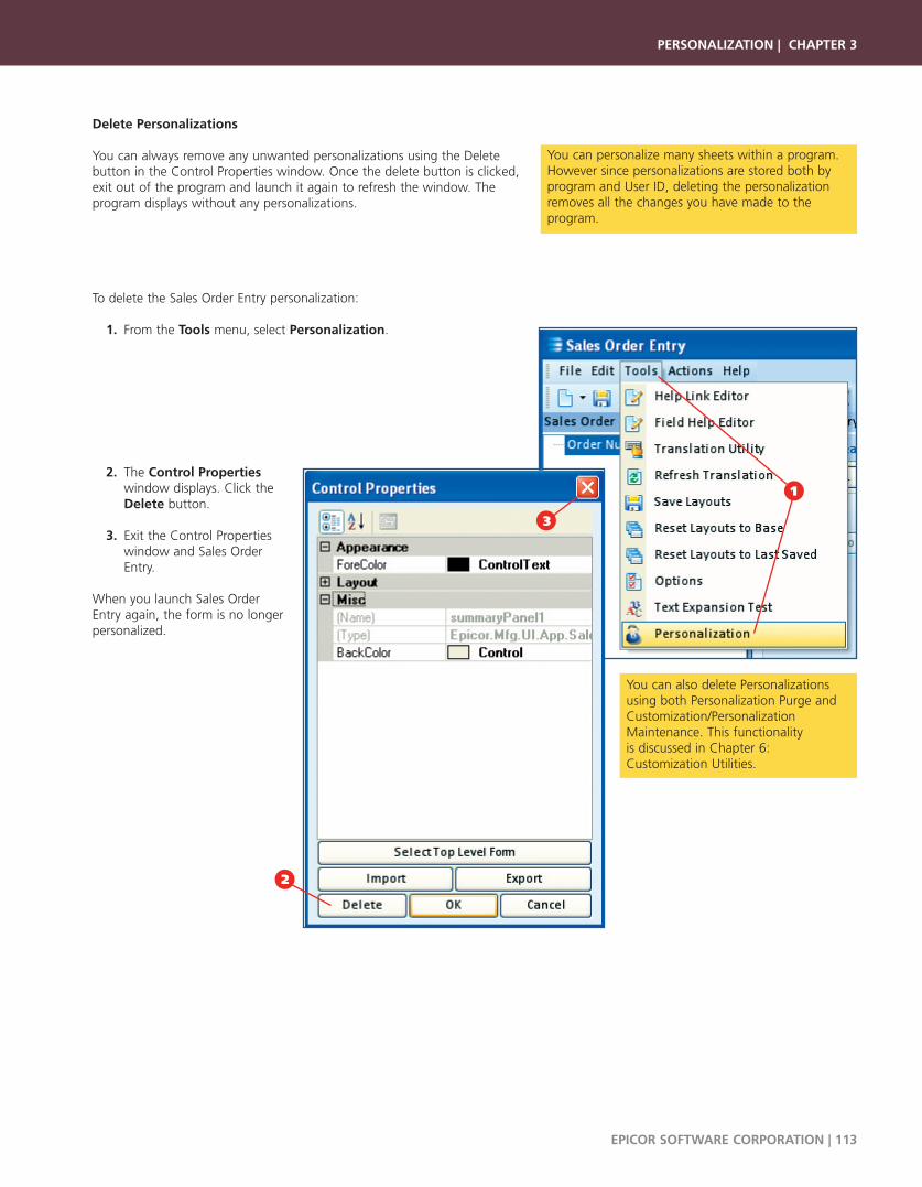
Delete Personalizations
You can always remove any unwanted personalizations using the Deletebutton in the Control Properties window. Once the delete button is clicked,exit out of the program and launch it again to refresh the window. Theprogram displays without any personalizations.
To delete the Sales Order Entry personalization:
1. From the Tools menu, select Personalization.
2. The Control Propertieswindow displays. Click theDelete button.
3. Exit the Control Properties window and Sales Order Entry.
When you launch Sales Order Entry again, the form is no longerpersonalized.
PERSONALIZATION | CHAPTER 3
EPICOR SOFTWARE CORPORATION | 113
You can personalize many sheets within a program.However since personalizations are stored both byprogram and User ID, deleting the personalizationremoves all the changes you have made to theprogram.
You can also delete Personalizationsusing both Personalization Purge andCustomization/PersonalizationMaintenance. This functionality is discussed in Chapter 6: Customization Utilities.
1
2
3

CHAPTER 3 | PERSONALIZATION
114 | EPICOR SOFTWARE CORPORATION