ep2r series - conairgroup.com
TRANSCRIPT

USER GUIDE www.conairgroup.com
UGH042-0713
Corporate Office: 724.584.5500 Instant Access 24/7 (Parts and Service): 800.458.1960 Parts and Service: 814.437.6861
EP2R Series Remote Air-cooled Condensers Scroll Compressor Chillers 5-40 tons

Corporate Office: 724.584.5500 Instant Access 24/7 (Parts and Service): 800.458.1960 Parts and Service: 814.437.6861
It’s a good idea to record the model and serial number(s) of your equipment and the date you received it in the User Guide. Our service department uses this information, along with the manual number, to provide help for the specific equipment you installed. Please keep this User Guide and all manuals, engineering prints and parts lists together for documentation of your equipment.
Date:
Manual Number: UGH042-0713
Serial Number(s):
Model Number(s):
Please record your equipment’s model and serial number(s) and the date you received it in the spaces provided.
DISCLAIMER: Conair shall not be liable for errors contained in this User Guide or for incidental, consequential damages in connection with the furnishing, performance or use of this information. Conair makes no warranty of any kind with regard to this information, including, but not limited to the implied warranties of merchantability and fitness for a particular purpose.
Copyright 2013 l Conair l All rights reserved

Corporate Office: 724.584.5500 Instant Access 24/7 (Parts and Service): 800.458.1960 Parts and Service: 814.437.6861
Table of Contents
Foreword ............................................................................................................................................................................. 1
Installation .......................................................................................................................................................................... 1 Receiving Inspection ................................................................................................................................................................ 1 Rigging, Handling, and Locating Equipment ............................................................................................................................. 1 Interconnecting Refrigerant Piping .......................................................................................................................................... 2 System and Piping Evacuation ................................................................................................................................................. 2 Electrical Power ........................................................................................................................................................................ 3
Refrigeration Piping Design ................................................................................................................................................. 3 General Design Considerations ................................................................................................................................................ 3
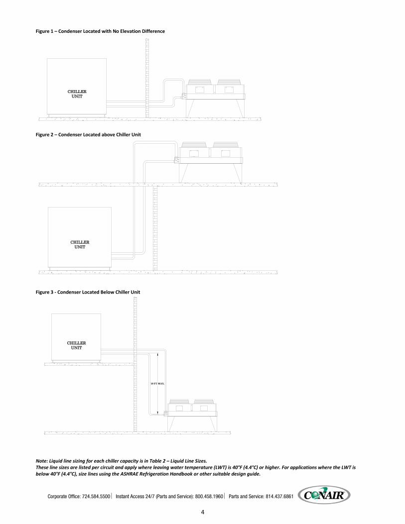
Figure 1 – Condenser Located with No Elevation Difference ............................................................................................... 4 Figure 2 – Condenser Located above Chiller Unit................................................................................................................. 4 Figure 3 - Condenser Located Below Chiller Unit ................................................................................................................. 4
Determining Equivalent Line Length ........................................................................................................................................ 5 Table 1 – Equivalent Lengths of Fittings ............................................................................................................................... 5
Liquid Line Sizing ...................................................................................................................................................................... 5 Table 2 – Liquid Line Sizes .................................................................................................................................................... 6
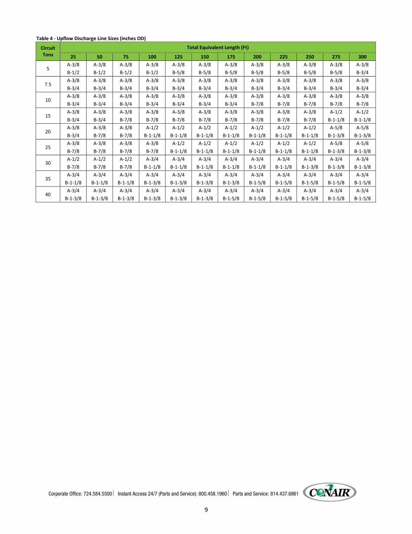
Discharge (Hot Gas) Line Sizing ................................................................................................................................................ 8 Figure 4 - Double Discharge Riser ......................................................................................................................................... 8 Table 3 - Horizontal or Downflow Discharge Line Sizes (inches OD) .................................................................................... 8 Table 4 - Upflow Discharge Line Sizes (inches OD) ............................................................................................................... 9
Calculating System Refrigerant and Oil Charge .................................................................................................................. 10 Table 5 – Combined Chiller and Remote Condenser Refrigerant Charge (Lbs. of refrigerant R-410A per Circuit) ............ 10 Table 6 - Field Piping Charge .............................................................................................................................................. 10
Oil Charge Determination ...................................................................................................................................................... 10 Setting Condenser Fan Controls ............................................................................................................................................. 11
Table 7 - Condenser Fan Control Pressure Settings ............................................................................................................ 11
Drawings ........................................................................................................................................................................... 11
We’re Here to Help ............................................................................................................................................................ 12 Equipment Guarantee ....................................................................................................................................................... 13


Corporate Office: 724.584.5500 Instant Access 24/7 (Parts and Service): 800.458.1960 Parts and Service: 814.437.6861
1
Foreword The intent of this manual is to serve as a guide for placing your remote condenser in service and operating and maintaining it properly. Improper installation can lead to poor equipment performance or severe equipment damage. Failure to follow the installation instructions may result in damage not covered by your warranty. It is extremely important that a qualified refrigeration installation contractor perform all installation line sizing and piping. Please supply these instructions to your authorized refrigeration contractor. This manual is for our standard product line with supplements as required to accommodate any special items provided for a specific application. The written information contained in this manual, as well as various drawings, are intended to be general in nature. The drawings included in this manual are typical only and may not represent the actual unit purchased. Actual drawings are included with the equipment for troubleshooting and servicing of the unit. Additional copies of drawings are available upon request. We strive to maintain an accurate record of all equipment during the course of its useful life. Every effort was made to standardize the design features of these chillers, the various options may make it necessary to rearrange some of the components; therefore, some of the general drawings in this manual may differ from your specific unit. Due to the ever-changing nature of applicable codes, ordinances, and other local laws pertaining to the use and operation of this equipment we do not reference them in this manual. There is no substitute for common sense and good operating practices when placing any mechanical equipment into operation. We encourage all personnel to familiarize themselves with this manual's contents. Failure to do so may unnecessarily prolong equipment down time. The chilling equipment uses chemical refrigerants for heat transfer purposes. This chemical is sealed and tested in a pressurized system containing ASME coded vessels; however, a system failure will release it. Refrigerant gas can cause toxic fumes if exposed to fire. Place these units in a well-ventilated area, especially if open flames are present. Failure to follow these instructions could result in a hazardous condition. We strongly recommend our customers implement a refrigerant management program including a survey of all equipment to document the type and quantity of refrigerant in each machine. We recommend all refrigeration service technicians be licensed and certified by an EPA approved organization. Follow good piping practices and the information in this manual to insure a successful installation and operation of this equipment. We are not responsible for liabilities created by substandard piping methods and installation practices external to the chiller. We trust your equipment will have a long and useful life. If you should have any questions, please contact our Customer Service Department specifying the serial number and model number of the unit as indicated on the nameplate.
Installation Receiving Inspection Each remote condenser unit has a holding charge of nitrogen. Before accepting delivery, check the overall equipment condition for any visible damage and document any evident on the delivery receipt. Shipping damage is the responsibility of the carrier. In order to expedite payment for damages, it is important to follow proper procedures and record keeping. Photographs of damaged equipment are excellent documentation for your records. Inspect for hidden damage after removing the packing. Refrigerant lines can be susceptible to damage in transit. Check for broken lines, oil leaks, damaged controls, or any other major component torn loose from its mounting point. Any sign of damage should be recorded and a claim filed immediately with the shipping company. Rigging, Handling, and Locating Equipment The condenser coil should be pressurized to 350 PSI (2413 kPa) with dry nitrogen gas and leak-checked prior to rigging. This will ensure no coil damage has occurred after the unit left the factory. The condenser ships with the legs removed. Mount the legs to the condenser using the provided nuts, bolts, and washers. Follow proper rigging methods to prevent damage to components. Avoid impact loading caused by sudden jerking when lifting or lowering the condenser. Use pads on any abrasive surface contact area.

Corporate Office: 724.584.5500 Instant Access 24/7 (Parts and Service): 800.458.1960 Parts and Service: 814.437.6861
2
CAUTION: Do not use the condenser manifolds, control panel, or return bends of the condenser coil for lifting or moving the condenser as this can result in significant damage to the unit.
The condenser is for outdoor use. A primary concern when designing your unit was serviceability; therefore, the condenser should be located in an accessible area. Install the unit on a firm, level base no closer than their width from walls or other condensers. Avoid locations near exhaust fans, plumbing vents, flues, or chimneys. Fasten the mounting legs at their base to the steel or concrete of the supporting structure. For units mounted on a roof structure, the steel support base holding the condenser should be elevated above the roof and attached to the building. Interconnecting Refrigerant Piping The chiller unit has a nitrogen holding charge and must be properly evacuated before charging with refrigerant. The chiller is for use only with the air-cooled condenser provided with the unit. The following section covers the required piping between the chiller and the provided air-cooled condenser. The chiller may consist of multiple evaporators, compressors, liquid line solenoid valves, expansion valves, sight glasses, filter driers, and receivers. If the chiller is to operate in lower ambient air temperatures, the chiller may also contain head pressure control valves. The discharge and liquid lines leaving the chiller have caps. These line sizes do not necessarily reflect the actual line sizes required for the piping between the chiller and the air-cooled condenser. The installing contractor need only provide the interconnecting piping between the chiller and the air-cooled condenser. Refrigerant piping size and piping design has a significant effect on system performance and reliability. Refer to the Refrigeration Line Sizing section of this manual to ensure the refrigerant piping and runs are proper. All piping should conform to the applicable local and state codes. Use refrigerant grade copper tubing only and isolate the refrigeration lines from building structures to prevent transfer of vibration. All copper tubing must have a pressure rating suitable for R-410A: tubing that is 3/4” OD or larger must be Type K rigid stick. ACR Coil may be used for sizes 5/8” ODS or smaller. Do not use a saw to remove end caps. This might allow copper chips to contaminate the system. Use a tube cutter or heat to remove the caps. When sweating copper joints it is important to evacuate all refrigerant present if any and flow dry nitrogen through the system. This prevents the formation of toxic gases, corrosive acids, and the formation of scale within the copper tube. Do not use soft solders. For copper-to-copper joints use a phos-copper solder with 6% to 8% silver content. Only use a high silver content brazing rod for copper-to-brass or copper-to-steel joints. Only use oxy-acetylene brazing.
CAUTION: The POE oil contained within the compressor is hygroscopic and has the ability to absorb water vapor from the atmosphere. Take necessary steps to prevent an open system from exposure to the atmosphere for extended time periods while installing the interconnecting refrigerant
System and Piping Evacuation The chiller and the remote condenser are shipped with a holding charge of nitrogen and must be properly evacuated before charging with refrigerant R-410A. Once the field piping is installed and pressure tested, the complete system, including the chiller, remote condenser and field piping must be evacuated. All solenoids and service valves including, service ball valves, receiver rotalock valves, compressor rotalock valves, liquid line solenoid valve, and etc. should be open during evacuation to ensure complete system evacuation. The system must be evacuated to 500 microns or less and not rise more than 100 microns for a minimum of 10 minutes after the vacuum pump is turned off and isolated from the system. Once evacuation is complete and the system has been charged with refrigerant, return all valves to their normal operating position. The chiller may be pre-evacuated while the field piping is being installed as long as the discharge and liquid line service valves remain closed to isolate the chiller from the field piping.

Corporate Office: 724.584.5500 Instant Access 24/7 (Parts and Service): 800.458.1960 Parts and Service: 814.437.6861
3
Electrical Power All wiring must comply with local codes and the National Electric Code. Minimum circuit ampacities and other unit electrical data are on the unit nameplate. Measure each leg of the main power supply voltage at the main power source. Voltage must be within the voltage utilization range shown in the unit nameplate. If the measured voltage on any leg is not within the specified range, notify the supplier and correct before operating the unit. Voltage imbalance must not exceed two percent. Excessive voltage imbalance between the phases of a three-phase system can cause motors to overheat and eventually fail. Voltage imbalance is determined using the following calculations: %Imbalance = (Vavg – Vx) x 100 / Vavg
Vavg = (V1 + V2 + V3) / 3 Vx = phase with greatest difference from Vavg
For example, if the three measured voltages are 442, 460, and 454 volts, the average would be: (442 + 460 + 454) / 3 = 452 The percentage of imbalance is then: (452 – 442) x 100 / 452 = 2.2 % This exceeds the maximum allowable of 2%. There is a terminal block for main power connection to the main power source. The main power source should be connected to the terminal block through an appropriate disconnect switch. There is also a separate lug in the main control panel for grounding the unit. Check the phase sequence at installation and prior to start-up with a phase sequence meter prior to applying power. The proper sequence should read “ABC” on the meter. If the meter reads “CBA”, open the main power disconnect and switch two line leads on the line power terminal blocks (or the unit mounted disconnect). All components requiring electric power are in-phase at the factory. Do not interchange any load leads that are from the unit contactors or the motor terminals.
Refrigeration Piping Design The system can be configured in any of the primary arrangements as shown in Figures 1 through 3 on the next page. The configuration and its associated elevation, along with the total distance between the chiller and the air-cooled condenser are important factors in determining the liquid line and discharge line sizes. This will also affect the field refrigerant charges. Consequently, it is important to adhere to certain physical limitations to ensure the system operates as designed. General Design Considerations 1. The total distance between the chiller and the air-cooled condenser must not exceed 200 actual feet (61 meters) or
300 equivalent feet (91 meters). 2. Liquid line risers must not exceed 15 feet (5 meters) in height from the condenser liquid line connection. (see Figure 3 -
Condenser Located Below Chiller Unit) 3. Discharge line risers cannot exceed an elevation difference greater than 100 actual feet (31 meters) without a
minimum of 2% efficiency decrease.
Corporate Office: 724.584.5500 Instant Access 24/7 (Parts and Service): 800.458.1960 Parts and Service: 814.437.6861
4
Figure 1 – Condenser Located with No Elevation Difference
Figure 2 – Condenser Located above Chiller Unit
Figure 3 - Condenser Located Below Chiller Unit
Note: Liquid line sizing for each chiller capacity is in Table 2 – Liquid Line Sizes. These line sizes are listed per circuit and apply where leaving water temperature (LWT) is 40°F (4.4°C) or higher. For applications where the LWT is below 40°F (4.4°C), size lines using the ASHRAE Refrigeration Handbook or other suitable design guide.
UNITCHILLER
UNITCHILLER
CHILLERUNIT
10 FT MAX.
CHILLER UNIT
CHILLER UNIT
CHILLER UNIT

Corporate Office: 724.584.5500 Instant Access 24/7 (Parts and Service): 800.458.1960 Parts and Service: 814.437.6861
5
Determining Equivalent Line Length To determine the appropriate size for field installed liquid and discharge lines, it is first necessary to establish the equivalent length of pipe for each line. The equivalent length is the actual friction loss from the linear run of pipe and the added friction loss of elbows, valves, etc. shows the equivalent length of pipe for various nonferrous valves and fittings. Follow these steps when calculating line size: 1. Start with an initial approximation of equivalent length by assuming that the equivalent length of pipe is 1.5 times the
actual pipe length. 2. Refer to Table 2 – Liquid Line Sizes (on the next page), Table 3 – Horizontal or Downflow Discharge Line Sizes (inches
OD) on page 8 and Table 4 – Upflow Discharge Line Sizes (inches OD) on page 9 for a first approximation of line size. 3. Check the line size by calculating the actual equivalent length using Table 1 – Equivalent Lengths of Fittings below. Note: When calculating the equivalent length, do not include piping of the chiller unit. Only field piping must be considered. Table 1 – Equivalent Lengths of Fittings
Line Size OD (in) Equivalent Lengths of Refrigerant Pipe (feet)
Elbow 90° Standard Elbow 90° Long Radius Elbow 90° Street Elbow 45° Standard Elbow 45° Long Radius 7/8 2.0 1.4 3.2 0.9 1.6
1 1/8 2.6 1.7 4.1 1.3 2.1 1 3/8 3.3 2.3 5.6 1.7 3.0 1 5/8 4.0 2.6 6.3 2.1 3.4 2 1/8 5.0 3.3 8.2 2.6 4.5 2 5/8 6.0 4.1 10.0 3.2 5.2 3 1/8 7.5 5.0 12.0 4.0 6.4 3 5/8 9.0 5.9 15.0 4.7 7.3 4 1/8 10.0 6.7 17.0 5.2 8.5
Liquid Line Sizing The liquid line diameter should be as small as possible while maintaining acceptable pressure drop. This is necessary to minimize refrigerant charge. The total length between the chiller unit and the air-cooled condenser must not exceed 200 actual feet (61 meters) or 300 equivalent feet (91 meters). Liquid line risers in the system will require an additional 0.5 PSIG (3.5 kPa) pressure drop per foot (31 cm) of vertical rise. When it is necessary to have a liquid line riser, make the vertical run immediately after the condenser before any additional restrictions. The liquid line risers must not exceed 15 feet (4.5 meters) in height from the condenser liquid line connection (see Figure 3 – Condenser Located Below Chiller Unit). The liquid line does not require pitching. Install a pressure tap valve at the condenser to facilitate measuring pressure for service. Liquid lines do not typically require insulation. However, if exposing the lines to solar heat gain or temperatures exceeding 110 °F (43°C), there is a negative effect on sub-cooling. In these situations, insulate the liquid lines.

Corporate Office: 724.584.5500 Instant Access 24/7 (Parts and Service): 800.458.1960 Parts and Service: 814.437.6861
6
Table 2 – Liquid Line Sizes
5 Ton Circuit 7.5 Ton Circuit
Total Equivalent Length (Ft)
Liquid Line Size (Inch OD) Total
Equivalent Length (Ft)
Liquid Line Size (Inch OD) Horizontal
or Downflow
Upflow 1 to 5 Feet
Upflow 6 to 10
Feet
Upflow 11 to 15
Feet
Horizontal or
Downflow
Upflow 1 to 5 Feet
Upflow 6 to 10
Feet
Upflow 11 to 15
Feet 25 1/2 1/2 1/2 1/2 25 5/8 5/8 5/8 5/8 50 1/2 1/2 1/2 1/2 50 5/8 5/8 5/8 5/8 75 1/2 1/2 1/2 1/2 75 5/8 5/8 5/8 5/8
100 1/2 1/2 1/2 3/4 100 5/8 5/8 5/8 5/8 125 1/2 1/2 1/2 5/8 125 5/8 5/8 5/8 5/8 150 1/2 1/2 5/8 5/8 150 5/8 5/8 5/8 5/8 175 1/2 5/8 5/8 5/8 175 5/8 5/8 5/8 3/4 200 1/2 5/8 5/8 5/8 200 5/8 5/8 5/8 3/4 225 5/8 5/8 5/8 5/8 225 5/8 5/8 5/8 3/4 250 5/8 5/8 5/8 5/8 250 5/8 5/8 3/4 3/4 275 5/8 5/8 5/8 5/8 275 5/8 5/8 3/4 3/4 300 5/8 5/8 5/8 5/8 300 5/8 5/8 3/4 3/4
10 Ton Circuit 15 Ton Circuit
Total Equivalent Length (Ft)
Liquid Line Size (Inch OD) Total
Equivalent Length (Ft)
Liquid Line Size (Inch OD) Horizontal
or Downflow
Upflow 1 to 5 Feet
Upflow 6 to 10
Feet
Upflow 11 to 15
Feet
Horizontal or
Downflow
Upflow 1 to 5 Feet
Upflow 6 to 10
Feet
Upflow 11 to 15
Feet 25 5/8 5/8 5/8 3/4 25 7/8 7/8 7/8 7/8 50 5/8 5/8 3/4 3/4 50 7/8 7/8 7/8 7/8 75 5/8 5/8 3/4 3/4 75 7/8 7/8 7/8 7/8
100 5/8 3/4 3/4 3/4 100 7/8 7/8 7/8 7/8 125 3/4 3/4 3/4 7/8 125 7/8 7/8 7/8 7/8 150 3/4 3/4 3/4 7/8 150 7/8 7/8 7/8 7/8 175 3/4 3/4 3/4 7/8 175 7/8 7/8 7/8 7/8 200 3/4 3/4 3/4 7/8 200 7/8 7/8 7/8 7/8 225 3/4 3/4 3/4 7/8 225 7/8 7/8 7/8 7/8 250 3/4 3/4 3/4 7/8 250 7/8 7/8 7/8 7/8 275 3/4 3/4 3/4 7/8 275 7/8 7/8 7/8 1 1/8 300 3/4 3/4 3/4 7/8 300 7/8 7/8 7/8 1 1/8

Corporate Office: 724.584.5500 Instant Access 24/7 (Parts and Service): 800.458.1960 Parts and Service: 814.437.6861
7
Table 2 – Liquid Line Sizes (continued) 20 Ton Circuit 25 Ton Circuit
Total Equivalent Length (Ft)
Liquid Line Size (Inch OD) Total
Equivalent Length (Ft)
Liquid Line Size (Inch OD) Horizontal
or Downflow
Upflow 1 to 5 Feet
Upflow 6 to 10
Feet
Upflow 11 to 15
Feet
Horizontal or
Downflow
Upflow 1 to 5 Feet
Upflow 6 to 10
Feet
Upflow 11 to 15
Feet 25 7/8 7/8 7/8 7/8 25 1 1/8 1 1/8 1 1/8 1 1/8 50 7/8 7/8 7/8 7/8 50 1 1/8 1 1/8 1 1/8 1 1/8 75 7/8 7/8 7/8 7/8 75 1 1/8 1 1/8 1 1/8 1 1/8
100 7/8 7/8 7/8 7/8 100 1 1/8 1 1/8 1 1/8 1 1/8 125 7/8 7/8 7/8 7/8 125 1 1/8 1 1/8 1 1/8 1 1/8 150 7/8 7/8 7/8 1 1/8 150 1 1/8 1 1/8 1 1/8 1 1/8 175 7/8 7/8 7/8 1 1/8 175 1 1/8 1 1/8 1 1/8 1 1/8 200 7/8 7/8 1 1/8 1 1/8 200 1 1/8 1 1/8 1 1/8 1 1/8 225 7/8 7/8 1 1/8 1 1/8 225 1 1/8 1 1/8 1 1/8 1 1/8 250 7/8 7/8 1 1/8 1 1/8 250 1 1/8 1 1/8 1 1/8 1 1/8 275 7/8 1 1/8 1 1/8 1 1/8 275 1 1/8 1 1/8 1 1/8 1 1/8 300 7/8 1 1/8 1 1/8 1 1/8 300 1 1/8 1 1/8 1 1/8 1 1/8
30 Ton Circuit 35 Ton Circuit
Total Equivalent Length (Ft)
Liquid Line Size (Inch OD) Total
Equivalent Length (Ft)
Liquid Line Size (Inch OD) Horizontal
or Downflow
Upflow 1 to 5 Feet
Upflow 6 to 10
Feet
Upflow 11 to 15
Feet
Horizontal or
Downflow
Upflow 1 to 5 Feet
Upflow 6 to 10
Feet
Upflow 11 to 15
Feet 25 1 1/8 1 1/8 1 1/8 1 1/8 25 1 1/8 1 1/8 1 1/8 1 1/8 50 1 1/8 1 1/8 1 1/8 1 1/8 50 1 1/8 1 1/8 1 1/8 1 1/8 75 1 1/8 1 1/8 1 1/8 1 1/8 75 1 1/8 1 1/8 1 1/8 1 1/8
100 1 1/8 1 1/8 1 1/8 1 1/8 100 1 1/8 1 1/8 1 1/8 1 1/8 125 1 1/8 1 1/8 1 1/8 1 1/8 125 1 1/8 1 1/8 1 1/8 1 1/8 150 1 1/8 1 1/8 1 1/8 1 1/8 150 1 1/8 1 1/8 1 1/8 1 1/8 175 1 1/8 1 1/8 1 1/8 1 1/8 175 1 1/8 1 1/8 1 1/8 1 3/8 200 1 1/8 1 1/8 1 1/8 1 1/8 200 1 1/8 1 1/8 1 1/8 1 3/8 225 1 1/8 1 1/8 1 1/8 1 1/8 225 1 1/8 1 1/8 1 1/8 1 3/8 250 1 1/8 1 1/8 1 1/8 1 1/8 250 1 1/8 1 1/8 1 3/8 1 3/8 275 1 1/8 1 1/8 1 1/8 1 1/8 275 1 1/8 1 1/8 1 3/8 1 3/8 300 1 1/8 1 1/8 1 1/8 1 3/8 300 1 1/8 1 1/8 1 3/8 1 3/8
40 Ton Circuit
Total Equivalent Length (Ft)
Liquid Line Size (Inch OD) Horizontal
or Downflow
Upflow 1 to 5 Feet
Upflow 6 to 10
Feet
Upflow 11 to 15
Feet 25 1 1/8 1 1/8 1 1/8 1 1/8 50 1 1/8 1 1/8 1 1/8 1 1/8 75 1 1/8 1 1/8 1 1/8 1 1/8
100 1 1/8 1 1/8 1 1/8 1 1/8 125 1 1/8 1 1/8 1 1/8 1 1/8 150 1 1/8 1 1/8 1 1/8 1 1/8 175 1 1/8 1 1/8 1 1/8 1 3/8 200 1 1/8 1 1/8 1 1/8 1 3/8 225 1 1/8 1 1/8 1 1/8 1 3/8 250 1 1/8 1 1/8 1 3/8 1 3/8 275 1 1/8 1 1/8 1 3/8 1 3/8 300 1 1/8 1 1/8 1 3/8 1 3/8

Corporate Office: 724.584.5500 Instant Access 24/7 (Parts and Service): 800.458.1960 Parts and Service: 814.437.6861
8
Discharge (Hot Gas) Line Sizing Discharge line size is based on the velocity needed to obtain sufficient oil return. Line length and restrictions should be minimized to reduce pressure drop and maximize capacity. The discharge lines should pitch downward, in the direction of the hot gas flow, at the rate of ½ inch (1.25 cm) per each 10 foot (3 meter) of horizontal run. If the chiller unit is below condenser, loop the discharge line to at least 1 inch (2.5 cm) above the top of the condenser. A pressure tap valve should be installed at the condenser to facilitate measuring pressure for service. If the chiller is below the condenser, consideration must be taken in the design of the discharge gas riser. All of our chillers have unloading capabilities via hot gas bypass or compressor unloading; therefore, they all require a double discharge riser for proper oil management. An example of the double discharge line construction is shown in Figure 4 below. Refer to Table 3 below to determine the size of the double discharge line riser. If the riser exceeds 25 feet (8 meters) in vertical height, the double discharge riser should be repeated for each 25 foot (8 meter) of rise. Figure 4 - Double Discharge Riser
Note: Discharge line sizing for each chiller capacity is in Table 3. Line sizing shown in Table 3 is listed per circuit and applies where leaving water temperature (LWT) is 40°F (4.4°C) or higher. For applications where LWT is below 40°F (4.4°C), size lines using the ASHRAE Refrigeration Handbook or other suitable design guide. Table 3 - Horizontal or Downflow Discharge Line Sizes (inches OD)
Circuit Tons
Total Equivalent Length (Ft)
25 50 75 100 125 150 175 200 225 250 275 300 5 5/8 5/8 5/8 5/8 3/4 3/4 3/4 ¾ 3/4 3/4 3/4 7/8
7.5 7/8 7/8 7/8 7/8 7/8 7/8 7/8 7/8 7/8 7/8 7/8 7/8 10 7/8 7/8 7/8 7/8 7/8 7/8 7/8 1-1/8 1-1/8 1-1/8 1-1/8 1-1/8 15 7/8 7/8 1-1/8 1-1/8 1-1/8 1-1/8 1-1/8 1-1/8 1-1/8 1-1/8 1-3/8 1-3/8 20 7/8 1-1/8 1-1/8 1-3/8 1-3/8 1-3/8 1-3/8 1-3/8 1-3/8 1-3/8 1-5/8 1-5/8 25 1-1/8 1-1/8 1-1/8 1-1/8 1-3/8 1-3/8 1-3/8 1-3/8 1-3/8 1-3/8 1-5/8 1-5/8 30 1-1/8 1-1/8 1-1/8 1-3/8 1-3/8 1-3/8 1-3/8 1-3/8 1-3/8 1-5/8 1-5/8 1-5/8 35 1-3/8 1-3/8 1-3/8 1-5/8 1-5/8 1-5/8 1-5/8 2-1/8 2-1/8 2-1/8 2-1/8 2-1/8 40 1-5/8 1-5/8 1-5/8 1-5/8 1-5/8 1-5/8 2-1/8 2-1/8 2-1/8 2-1/8 2-1/8 2-1/8
CONDENSERPITCH TO
A B
REDUCINGTEE
CHILLERFROM
STREET ELBOWS45 DEGREE
STREET ELBOW90 DEGREE
Corporate Office: 724.584.5500 Instant Access 24/7 (Parts and Service): 800.458.1960 Parts and Service: 814.437.6861
9
Table 4 - Upflow Discharge Line Sizes (inches OD)
Circuit Tons
Total Equivalent Length (Ft)
25 50 75 100 125 150 175 200 225 250 275 300
5 A-3/8 A-3/8 A-3/8 A-3/8 A-3/8 A-3/8 A-3/8 A-3/8 A-3/8 A-3/8 A-3/8 A-3/8 B-1/2 B-1/2 B-1/2 B-1/2 B-5/8 B-5/8 B-5/8 B-5/8 B-5/8 B-5/8 B-5/8 B-3/4
7.5 A-3/8 A-3/8 A-3/8 A-3/8 A-3/8 A-3/8 A-3/8 A-3/8 A-3/8 A-3/8 A-3/8 A-3/8 B-3/4 B-3/4 B-3/4 B-3/4 B-3/4 B-3/4 B-3/4 B-3/4 B-3/4 B-3/4 B-3/4 B-3/4
10 A-3/8 A-3/8 A-3/8 A-3/8 A-3/8 A-3/8 A-3/8 A-3/8 A-3/8 A-3/8 A-3/8 A-3/8 B-3/4 B-3/4 B-3/4 B-3/4 B-3/4 B-3/4 B-3/4 B-7/8 B-7/8 B-7/8 B-7/8 B-7/8
15 A-3/8 A-3/8 A-3/8 A-3/8 A-3/8 A-3/8 A-3/8 A-3/8 A-3/8 A-3/8 A-1/2 A-1/2 B-3/4 B-3/4 B-7/8 B-7/8 B-7/8 B-7/8 B-7/8 B-7/8 B-7/8 B-7/8 B-1-1/8 B-1-1/8
20 A-3/8 A-3/8 A-3/8 A-1/2 A-1/2 A-1/2 A-1/2 A-1/2 A-1/2 A-1/2 A-5/8 A-5/8 B-3/4 B-7/8 B-7/8 B-1-1/8 B-1-1/8 B-1-1/8 B-1-1/8 B-1-1/8 B-1-1/8 B-1-1/8 B-1-3/8 B-1-3/8
25 A-3/8 A-3/8 A-3/8 A-3/8 A-1/2 A-1/2 A-1/2 A-1/2 A-1/2 A-1/2 A-5/8 A-5/8 B-7/8 B-7/8 B-7/8 B-7/8 B-1-1/8 B-1-1/8 B-1-1/8 B-1-1/8 B-1-1/8 B-1-1/8 B-1-3/8 B-1-3/8
30 A-1/2 A-1/2 A-1/2 A-3/4 A-3/4 A-3/4 A-3/4 A-3/4 A-3/4 A-3/4 A-3/4 A-3/4 B-7/8 B-7/8 B-7/8 B-1-1/8 B-1-1/8 B-1-1/8 B-1-1/8 B-1-1/8 B-1-1/8 B-1-3/8 B-1-3/8 B-1-3/8
35 A-3/4 A-3/4 A-3/4 A-3/4 A-3/4 A-3/4 A-3/4 A-3/4 A-3/4 A-3/4 A-3/4 A-3/4
B-1-1/8 B-1-1/8 B-1-1/8 B-1-3/8 B-1-3/8 B-1-3/8 B-1-3/8 B-1-5/8 B-1-5/8 B-1-5/8 B-1-5/8 B-1-5/8
40 A-3/4 A-3/4 A-3/4 A-3/4 A-3/4 A-3/4 A-3/4 A-3/4 A-3/4 A-3/4 A-3/4 A-3/4
B-1-3/8 B-1-3/8 B-1-3/8 B-1-3/8 B-1-3/8 B-1-3/8 B-1-5/8 B-1-5/8 B-1-5/8 B-1-5/8 B-1-5/8 B-1-5/8

Corporate Office: 724.584.5500 Instant Access 24/7 (Parts and Service): 800.458.1960 Parts and Service: 814.437.6861
10
Calculating System Refrigerant and Oil Charge The approximate amount of the refrigerant charge required by the system can be determined by using Table 1 – Equivalent Lengths of Fittings on page 5 and Table 2 – Liquid Line Sizes on page 6. To verify the system charge, run the system and check the liquid line sight glasses. To determine the approximate charge, first refer to Table 5 – Combined Chiller and Remote Condenser Refrigerant Charge (Lbs. of refrigerant R-410A per Circuit) below and establish the required charge for the condenser and chiller. Values given in Table 5 are per circuit. Then refer to Table 6 – Field Piping Charge to determine the charge required for the field-installed piping per circuit. The approximate charge per circuit is therefore the sum of the values from Tables 5 and 6. Table 5 – Combined Chiller and Remote Condenser Refrigerant Charge (Lbs. of refrigerant R-410A per Circuit)
Chiller Model
Minimum Design Ambient - °F 40 20 0 -20
EP2R5 32 33 34 34 EP2R8 37 40 41 42
EP2R10 33 37 39 41 EP2R15 39 46 49 51 EP2R20 66 78 85 89 EP2R25 50 53 59 64 EP2R30 69 73 81 88 EP2R35 91 91 98 111 EP2R40 110 110 120 137
Table 6 - Field Piping Charge
Line Size OD (inches) Refrigerant R-410A Charge (pounds) Per 100 Feet of Run
Discharge Line Liquid Line 3/8 0.3 3.2 1/2 0.6 6 5/8 1 19.6 3/4 1.5 14.4 7/8 2.1 20
1-1/8 3.7 34.1 1-3/8 5.6 52 1-5/8 7.9 73.6 2-1/8 13.7 128
Oil Charge Determination The chiller is factory charged with the amount of oil required by the chiller only and not the total system. Refer to the manual that came with the chiller to determine the type of oil used. The amount of oil required is dependent upon the amount of refrigerant that is added to the system for the field-installed piping. Calculate the amount of oil to be added, using the following formula:
Pints of Oil = Lbs. of refrigerant added / 100 Oil level should be checked after the chiller has run for 15 minutes.

Corporate Office: 724.584.5500 Instant Access 24/7 (Parts and Service): 800.458.1960 Parts and Service: 814.437.6861
11
Setting Condenser Fan Controls Depending on the number of condenser fans present in the condenser there will be different fan cycling pressure control settings requirements. It is important that these setting be correct in order to maintain proper capacity control and operation of the system. Each refrigerant circuit has a separate head pressure control circuit. The proper pressure settings are shown in Table 7 below. Table 7 - Condenser Fan Control Pressure Settings
Number of Fan Stages 1 2 3 4
Stage 1 Max Speed 410 410 410 410 Min Speed 320 320 320 320
Stage 2 Fan On 400 400 370 Fan Off 340 340 305
Stage 3 Fan On 435 385 Fan Off 375 325
Stage 4 Fan On 400 Fan Off 340
Note: Dual circuit condensers have two separate head-pressure controls circuits.
Drawings We have prepared a custom set of drawings for your unit and placed them inside the shipping box or control panel prior to shipment. Please refer to these drawings when troubleshooting, servicing, and installing the unit. If you cannot find these drawings or wish to have additional copies sent, please contact our Customer Service Department and reference the serial number of your unit. The drawings included in this manual are typical only and may not represent the actual unit purchased.

Corporate Office: 724.584.5500 Instant Access 24/7 (Parts and Service): 800.458.1960 Parts and Service: 814.437.6861
12
We’re Here to Help Conair has made the largest investment in customer support in the plastics industry. Our service experts are available to help with any problem you might have installing and operating your equipment. Your Conair sales representative also can help analyze the nature of your problem, assuring that it did not result from misapplication or improper use.
How to Contact Customer Service To contact Customer Service personnel, call:
NOTE: Normal operating hours are 8:00 am - 5:00 pm EST. After hours emergency service is available at the same phone number.
From outside the United States, call: 814-437-6861 You can commission Conair service personnel to provide on-site service by contacting the Customer Service Department. Standard rates include an on-site hourly rate, with a one-day minimum plus expenses.
Before You Call... If you do have a problem, please complete the following checklist before calling Conair:
r Make sure you have all model, control type from the serial tag, and parts list numbers for your particular equipment. Service personnel will need this information to assist you.
r Make sure power is supplied to the equipment.
r Make sure that all connectors and wires within and between control systems and related components have been installed correctly.
r Check the troubleshooting guide of this manual for a solution.
r Thoroughly examine the instruction manual(s) for associated equipment, especially controls. Each manual may have its own troubleshooting guide to help you.
r Check that the equipment has been operated as described in this manual.
r Check accompanying schematic drawings for information on special considerations.
Additional manuals and prints for your Conair equipment may be ordered through the Customer Service or Parts Department for a nominal fee.
Corporate Office: 724.584.5500 Instant Access 24/7 (Parts and Service): 800.458.1960 Parts and Service: 814.437.6861
13
Equipment Guarantee Conair guarantees the machinery and equipment on this order, for a period as defined in the quotation from date of shipment, against defects in material and workmanship under the normal use and service for which it was recommended (except for parts that are typically replaced after normal usage, such as filters, liner plates, etc.). Conair’s guarantee is limited to replacing, at our option, the part or parts determined by us to be defective after examination. The customer assumes the cost of transportation of the part or parts to and from the factory.
Performance Warranty Conair warrants that this equipment will perform at or above the ratings stated in specific quotations covering the equipment or as detailed in engineering specifications, provided the equipment is applied, installed, operated and maintained in the recommended manner as outlined in our quotation or specifications.
Should performance not meet warranted levels, Conair at its discretion will exercise one of the following options:
• Inspect the equipment and perform alterations or adjustments to satisfy performance claims. (Charges for suchinspections and corrections will be waived unless failure to meet warranty is due to misapplication, improperinstallation, poor maintenance practices or improper operation.)
• Replace the original equipment with other Conair equipment that will meet original performance claims at no extracost to the customer.
• Refund the invoiced cost to the customer. Credit is subject to prior notice by the customer at which time a ReturnGoods Authorization Number (RGA) will be issued by Conair’s Service Department. Returned equipment must bewell crated and in proper operating condition, including all parts. Returns must be prepaid.
Purchaser must notify Conair in writing of any claim and provide a customer receipt and other evidence that a claim is being made.
Warranty Limitations Except for the Equipment Guarantee and Performance Warranty stated above, Conair disclaims all other warranties with respect to the equipment, express or implied, arising by operation of law, course of dealing, usage of trade or otherwise, including but not limited to the implied warranties of merchantability and fitness for a particular purpose.