ep2525185 a1
TRANSCRIPT
Printed by Jouve, 75001 PARIS (FR)
(19)E
P2
525
185
A1
TEPZZ 5 5_85A_T(11) EP 2 525 185 A1
(12) EUROPEAN PATENT APPLICATIONpublished in accordance with Art. 153(4) EPC
(43) Date of publication: 21.11.2012 Bulletin 2012/47
(21) Application number: 10842784.0
(22) Date of filing: 15.01.2010
(51) Int Cl.:F41A 19/06 (2006.01) F41C 3/00 (2006.01)
(86) International application number: PCT/BR2010/000015
(87) International publication number: WO 2011/085458 (21.07.2011 Gazette 2011/29)
(84) Designated Contracting States: AT BE BG CH CY CZ DE DK EE ES FI FR GB GR HR HU IE IS IT LI LT LU LV MC MK MT NL NO PL PT RO SE SI SK SM TR
(71) Applicant: Forjas Taurus S/A.91360-000 Porto Alegre - RS (BR)
(72) Inventor: SILVEIRA, Nilton da91120-410 Porto Alegre - RS (BR)
(74) Representative: Chimini, FrancescoJacobacci & Partners S.p.A. Piazza della Vittoria, 11I-25122 Brescia (IT)
(54) PISTOL WITH FIRING MECHANISM THAT CAN EASILY BE ADAPTED TO VARIOUS MODES OF OPERATION
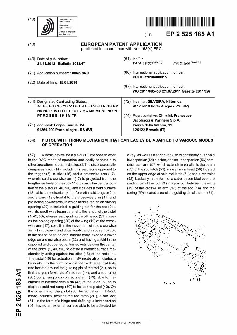
(57) A basic device for a pistol (1), intended to workin the DAO mode of operation and easily adaptable toother operation modes, is disclosed. The pistol especiallycomprises a rod (14), including, in said edge opposed tothe trigger (5), a stick (16) and a crosswise arm (17),wherein said crosswise arm (17) is projected from thelengthwise body of the rod (14), towards the central por-tion of the pistol (1, 40, 50), and includes a front surface(18), able to mechanically interfere with said tongue (24),and a wing (19), frontal to the crosswise arm (17) andprojecting downwards, in which middle region an oblongopening (20) is included; a guiding pin for the rod (21),with its lengthwise beam parallel to the length of the pistol(1, 49, 50), wherein said guiding pin of the rod (21) cross-es the oblong opening (20) of the wing (19) of the cross-wise arm (17), so to limit the movement of said crosswisearm (17) upwards and downwards; and a rod ramp (30),in the shape of an oblong laminar body, fixed to a loweredge on a crosswise beam (22) and having a fold in theopposed and upper edge, turned outside over the centerof the pistol (1, 40, 50), to define a contact surface me-chanically acting against the stick (16) of the rod (14).The pistol (40) for actuation in SA mode also includes abush (42), in the form of a cylinder with a central holeand located around the guiding pin of the rod (21), so tolimit the path forwards of said rod (14); and a rod ramp(30’) comprising a disconnecting arm (43), able to me-chanically interfere with a rib (45) of the latch (6), so todisplace said rod ramp (30’) to inside the pistol (40). Onthe other hand, the pistol (50) for actuation in DA/SAmode includes, besides the rod ramp (30’), a rod lock(51), in the form of a hinge and defining: a lower portion(54) having an external surface able to be activated by
a key, as well as a spring (55), so to constantly push saidlower portion (54) outside, and an upper portion (56) com-prising an arm (57) which extends in parallel to the beam(53) of the rod latch (51), as well as a head (58) locatedon the upper edge of said rod latch (51); and a restraint(52), basically in the form of a cube, assembled over theguiding pin of the rod (21) in a position between the wing(19) of the crosswise arm (17) of the rod (14) and thespring (59) located around the guiding pin of the rod (21).

EP 2 525 185 A1
2
5
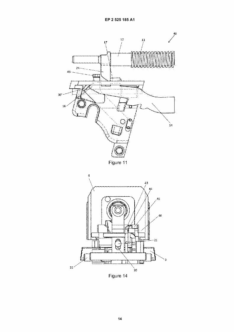
10
15
20
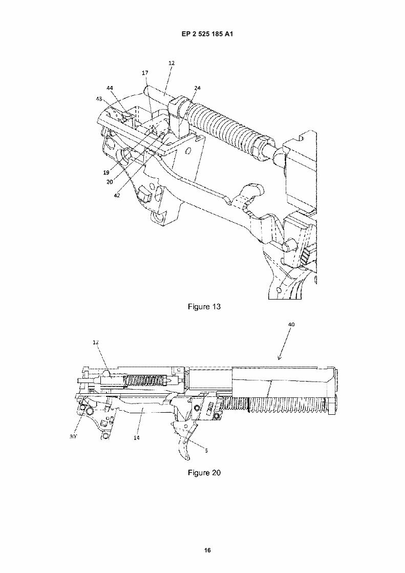
25
30
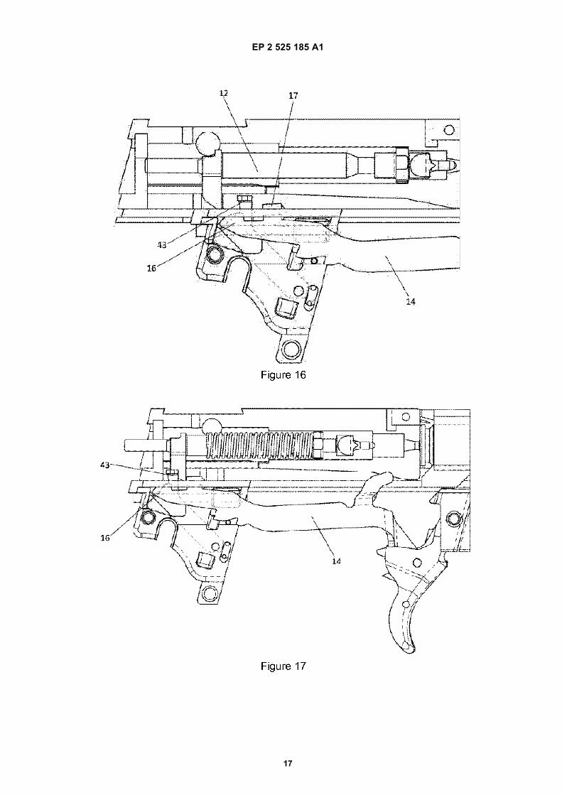
35
40
45
50
55
Description
FIELD OF THE INVENTION
[0001] The present invention refers to a pistol, morespecifically a pistol comprising a firing device presentinga basic configuration which is easily modifiable for actu-ation in different modes of operation.
BASICS OF THE ART
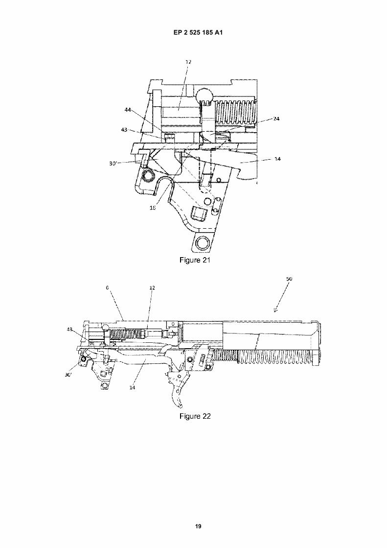
[0002] The state of the art referring to fire guns, morespecifically pistols, has for long incorporated variousprojects of firing devices, each one with its particularities.These firing devices can be divided in specific groupsaccording to the mode of operation of the pistol, such as:single action (SA); double action (DA); or mixed (DA/SA),i. e. they can operate both in the single action mode andthe double action mode, depending on the positioning ofa given mechanical element of control, usually a side keyover the body of the pistol. No matter which is the modeof operation, a common characteristic to all these pistolsis the presentation of a specific project and/or device foreach one. However, we are unaware of a pistol or a firingdevice for a pistol, rationalizing its production, so to en-able to make models with different modes of operation,but with similar characteristics of operation/components.
SUMMARY OF THE INVENTION
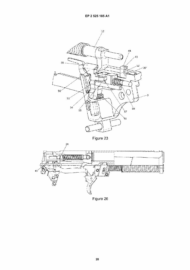
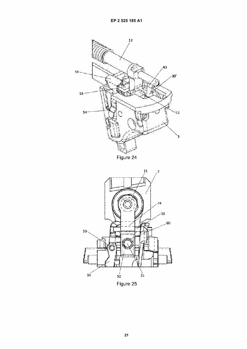
[0003] Therefore, it is a main object of the present in-vention to supply a firing device for a pistol which, with afew changes, may be converted so to operate in doubleaction, single action and alternative double action/singleaction modes.[0004] Furthermore, another object of the present in-vention is constituted by a family or a series of pistols,comprising double action pistols, single action pistols andalternate (double or single) action pistols, produced froma basic project, so to reduce the costs of the project,production and assembly of their components and body,thus allowing an optimization of the project and thereforeof the final pistols, whichever is their mode of operation.[0005] The objects above are reached and satisfied bya basic pistol, intended to activate, in the DAO mode, apistol with a firing device which is easily adaptable tovarious modes of operation, comprising a wrist overwhich a latch is moved, said wrist comprising a butt, in-side which the comb, the trigger guard involving the trig-ger and a metal back support, intended to lodge part ofthe components of the pistol firing device, wherein saidfiring device comprises said trigger, hinged in pivot to afirst edge of the rod, the opposed edge of said rod islocated on the back support, said latch involves and lodg-es the percussor, located behind and aligned to thechamber wherein the cartridge is located, and said latchhas, around its front portion, the spring of the percussor,acting over the backstop and, on its back portion, a
tongue projecting downwards. Said pistol also comprisesa rod, in the shape of a laminar element forming andincluding, in said edge opposed to the trigger, a stick anda crosswise arm, wherein said crosswise arm is projectedfrom the lengthwise body of the rod, towards the centralportion of the pistol, and includes a front surface, able tomechanically interfere with said tongue, and a wing, fron-tal to the crosswise arm and projecting downwards, inwhich middle region an oblong opening is included; aguiding pin for the rod, fixed to the back support, with itslongitudinal beam parallel to the length of the piston,wherein said guiding pin of the rod crosses the oblongopening of the wing of the crosswise arm, so to limit themovement of said crosswise arm upwards and down-wards; and a rod ramp, in the shape of an oblong laminarbody, fixed to a lower edge on a crosswise beam andhaving a fold in the opposed and upper edge, turned out-side over the center of the pistol, to define a contact sur-face mechanically acting against the rod stick.[0006] From the above basic pistol, a pistol intendedto act in the SA mode is also disclosed, which firing devicealso includes: a bush, in the form of a cylinder with acentral hole and located around the guiding pin of the rodand ahead of the wing of the crosswise arm of the rod,so to limit the path forwards of said rod; and a rod rampalso comprising a disconnecting arm, which is verticallyprojected upwards and includes, in its upper edge, a pro-jection able to mechanically interfere with a rib, locatedon the internal side of the fixing wing wherein said latchslides, so to displace said rod ramp to inside the pistol.[0007] Finally, a second alternative model of pistol, in-tended to work in the DA/SA mode, is included, also com-prising: a rod ramp also comprising a disconnecting arm,which is vertically projected upwards and includes, on itsupper edge, a projection able to mechanically interferewith a rib, located on the internal side of the fixing wingwherein said latch slides, so to displace said rod rampto inside the pistol; a rod latch in the form of a hinge overa respective beam located in parallel to the lengthwisebeam of the pistol, defining: a lower portion of said rodlatch, having an external surface able to be activated bya key, as well as a spring, located in the internal part ofsaid lower portion, so to constantly push said lower por-tion outside, and an upper portion of the rod latch, com-prising an arm which is extended in parallel to the rodlatch beam, as well as a head located on the upper edgeof said rod latch; and a restraint, basically in the form ofa cube, provided with a central hole through which saidrestraint is assembled over the guiding pin of the rod ina position between the wing of the crosswise arm of therod and the spring located around the guiding pin of therod.
BRIEF DESCRIPTION OF DRAWINGS
[0008] The object of the present invention will be betterunderstood in the light of the detailed disclosure below,presented as an illustration and not a limitation, with ref-
1 2

EP 2 525 185 A1
3
5
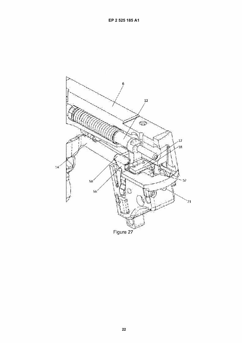
10
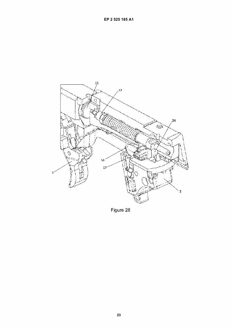
15
20
25
30
35
40
45
50
55
erence to the attached figures, wherein:[0009] - Figure 1 is an upper side view of a pistol of thepresent invention, in partial section and showing its maincomponents;[0010] - Figures 2 to 10 are schematic views showinga pistol with DAO mode of operation, in partial sectionand corresponding to the various steps of operation ofthis embodiment of the invention;[0011] - Figures 11 to 20 are schematic views showinga firing device for a pistol of the present invention, onlyoperated in the single action mode, with the changeddevice over the basic firing device as shown by Figures2 to 10; and[0012] - Figures 21 to 28 are schematic views showinga firing device for a pistol of the present invention, oper-ated in the double action/single action mode.
DETAILED DESCRIPTION OF THE INVENTION
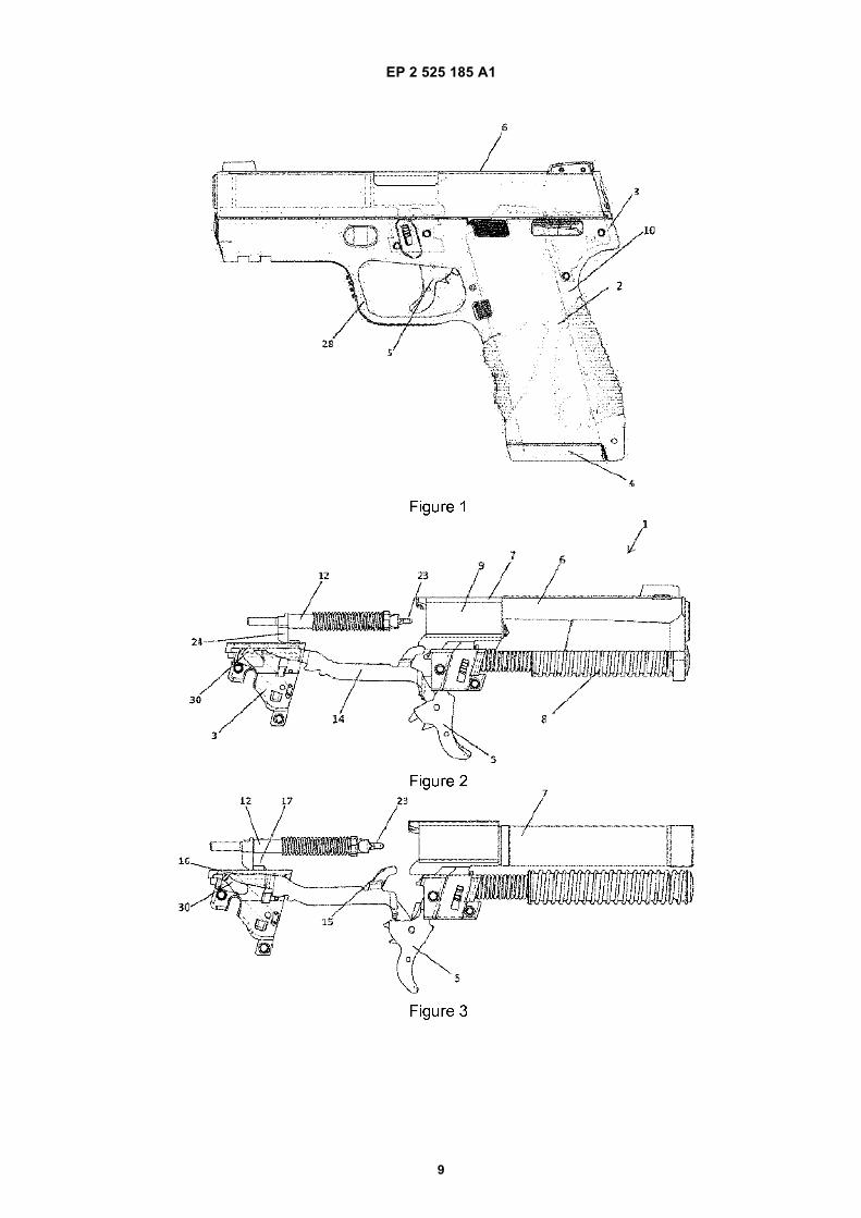
[0013] According to the present invention, the objectsare reached thanks to a firing device for a pistol with onlydouble action (DAO), which mechanism may be easilymodified to reach a single action (SA) pistol and also adouble/single action (DA/SA) pistol.[0014] Figure 1 is a schematic upper side view of apistol 1 only of the double action (DAO) type, having awrist 10, including the butt 2, located on its lower backportion, the lower part of the latch 6 and the guides (notshown) to slide said latch 6 over the wrist 10. In a pref-erable embodiment of the invention, the wrist 10 is aninjected polymeric structure provided with a few metalinsertions, wherein said guides to slide the latch 6, aswell as the back support 3, located above the butt 2 andintended to lodge part of the components of the firingdevice of the pistol 1, which will be disclosed in detailfurther below. Furthermore, the trigger guard 28 is alsoformed as a single part from the wrist 10. Inside the butt2, a lodgment is included to receive the comb 4 intendedto store and supply the cartridges 11 as known.[0015] In an advanced position over the butt 2, the trig-ger 5 is included, which is hinged to said wrist 10 of thepistol 1 or, more specifically, said trigger 5 is hinged tothe central support of the wrist 10, which is a metal partlodged inside the wrist 10. The upper portion of the pistolcomprises the latch 6 which can be transported over saidstructure of the wrist 10, by means of said four guides(not shown) which, in their frontal portion, involve the pipe7 and the respective return spring 8. In a front positionover the pipe 7, the chamber 9 is included to lodge acartridge 11, which chamber is located, with the pistol 1in a resting position, in a lengthwise quota equal to thetrigger 5. Furthermore, the back portion of the latch 6covers the percussor 12 and the respective spring of thepercussor 13.[0016] More specifically, Figures 2 to 10, showingschematic views of the firing device for the pistol 1 oper-ated only in the double action (DAO) mode, show com-ponents of the firing device, with parts removed not to
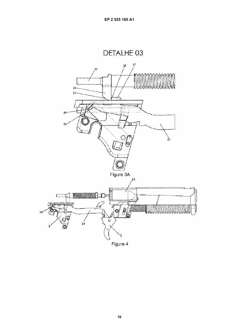
compromise the clarity of the figures.[0017] Therefore, the trigger 5, hinged to said centralsupport of the wrist 10, is hinged to the rod 14, so thatthe movements made by the trigger 5 are sent to the rod14 and vice versa. Said rod 14 has the shape of a con-formed laminar element and includes, on its opposededge to the trigger 5, a stick 16 and a crosswise arm 17.More specifically, the crosswise arm 17 is projected fromthe lengthwise body of the rod 14 towards the centralportion of the pistol 1, and having a front surface 18, ableto mechanically interfere with a tongue 24 projected fromthe percussor 12 and a wing 19, frontal to the crosswisearm 17 and projected downwards, in which central regionan oblong opening 20 is included, inside which the guid-ing pin of the rod 21 is included. The guiding pin of therod 21 is fixed to said metal back support of the wrist 10and is intended to limit the movement upwards and down-wards of the rod 14, but not its back and forth translation.[0018] Said stick 16 of the rod 14 acts over the rodramp 30 which, on a lower edge, is fixed to a crosswisebeam 22 and, on the opposed and upper edge, has afold towards the outside of the center of the pistol 1, thusdefining a contact surface with the stick 16 of the rod 14.[0019] As stated, the percussor 12 is located inside theregion as limited by the latch 6 and is able to move freely,back and forth, from said latch 6. More particularly, thepercussor 12 has a cylindrical shape, frontally providedwith a stick 23 for the percussion of the cartridge 11, andhaving a frontal tongue 24, which forms a ramp 27 on itslower back portion, intended to mechanically interact withthe crosswise arm 17 of the rod 14. Furthermore, andaround the central portion of the percussor 12, said springof the percussor 13 is located.[0020] A few other details of the above components,as well as the form of operation of the device of thepresent invention in the double action mode of operation,will now be particularly explained based on Figures 2 to10.[0021] On Figure 2 (and also 10), the pistol 1 is muni-tioned, i. e. it has a cartridge 11 in the respective chamber9 with the comb 4 loaded, as well as a trigger 5 in startingcourse, i. e. in its most advanced position. Therefore, theuser starts the firing procedure by moving the trigger 5backwards, causing the movement of the rod 14 in thesame direction. Such movement of the rod 14 is guidedthrough the guiding pin 21 of the rod, so to guaranteethat said rod 14 is not displaced upwards. Consequently,and due to the mechanical interference between the frontsurface 18 of the crosswise arm 17 of the rod 14 with thetongue 24 of the percussor 12, said percussor 12 willalso be moved backwards against the resistance as im-posed by the spring of the percussor 13, as shown byFigure 2.[0022] That same position is shown by Figure 3 in itsrespective enlarged detail (DET 3), which is an enlargedview of the back support 3 of the pistol 1, from which wecan notice that, in that point of the movement, the stick16 of the rod 14 keeps contact with the rod ramp 30, thus
3 4

EP 2 525 185 A1
4
5
10
15
20
25
30
35
40
45
50
55
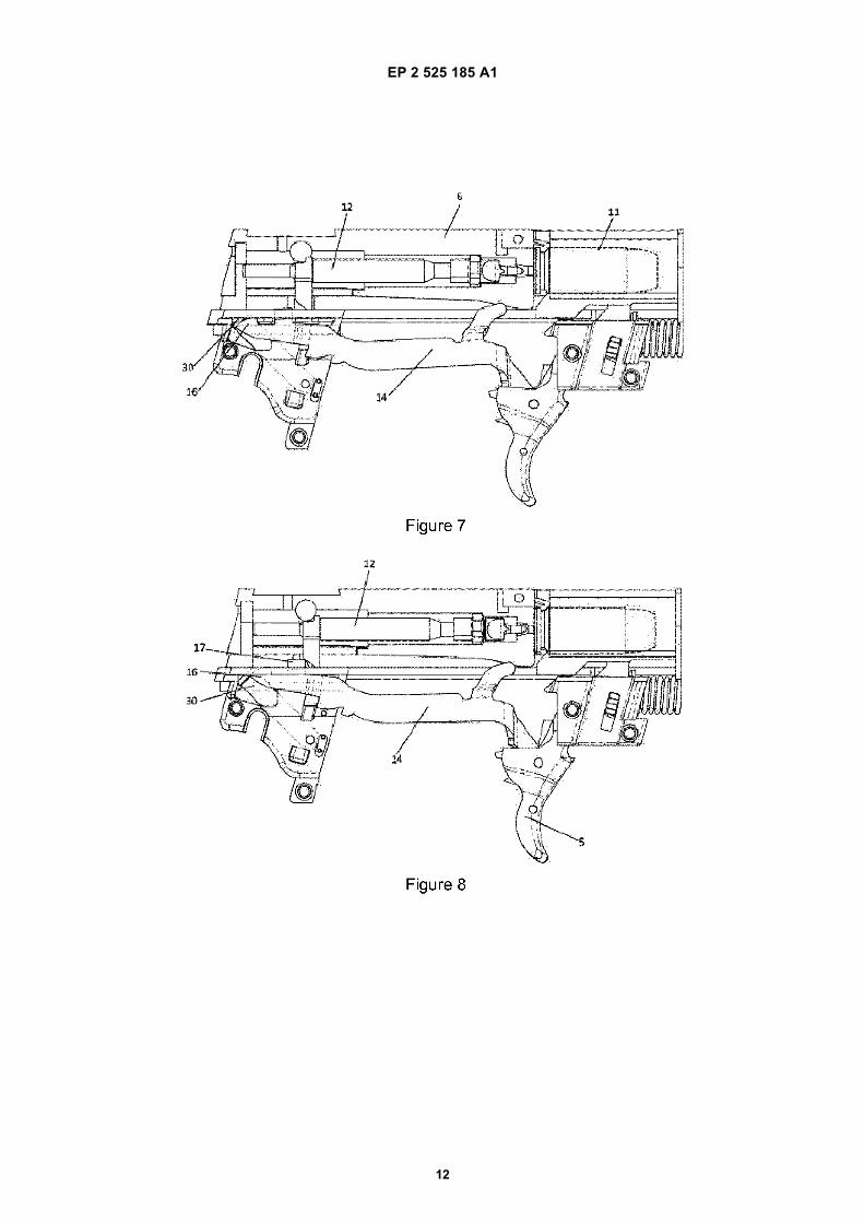
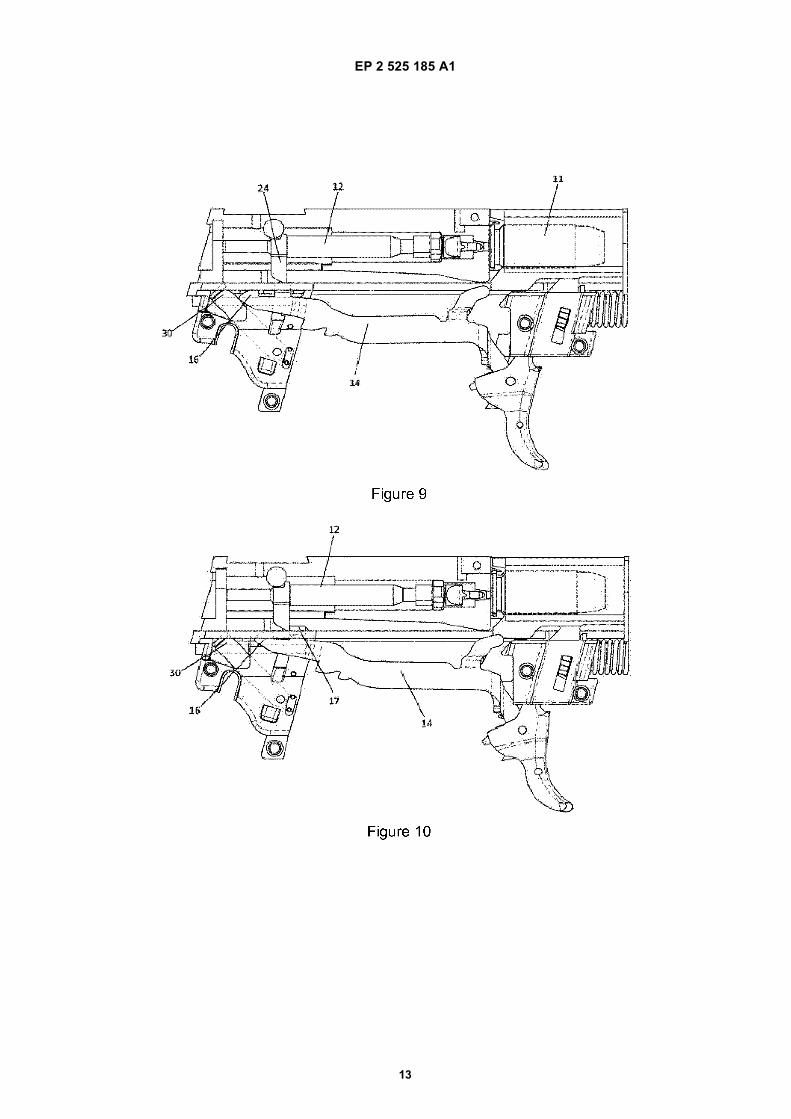
forcing said rod 14 below and therefore lowering thecrosswise arm 17 until the release of the tongue 24 ofthe percussor 12.[0023] At that moment, i. e. when the crosswise arm17 no longer works against the tongue 24 of the percus-sor, said percussor 12 is pushed frontwards by the actionof the spring 13, causing the percussion of the ammuni-tion located inside the chamber 9 of the pipe 7, throughits stick 23. Particularly, Figures 4 and 5 show the mo-ment of the percussion of the cartridge 11, wherein wecan see the rod 14 in its maximum lower position and thetongue 24 of the percussor advanced over the crosswisearm 17 of the rod 14.[0024] From this point, the so-called cycling starts, i.e. the procedure to eliminate the fired cartridge, reloadthe chamber with a new cartridge and reposition the firingdevice for new firing. Said sequence of events is shown,step by step, on Figures 6 to 10.[0025] Therefore, after the firing and during latch 6 cy-cling, caused by the gas expansion in the cartridge, thepercussor 12 follows backwards together with the latch6 (please see Figure 6 - maximum backwards positionof the latch). After the latch ends the quick clicking proc-ess, supplying the chamber 9 and returning to the front,the user starts to release the trigger 5, causing the rod14 of the trigger to follow said movement to the front(please see Figure 7). During the movement of the guide14 backwards, its crosswise arm 17 hits the ramp 27 ofthe tongue 24, thus forcing said rod 14 downwards(please Figures 8 and 9). This movement downwards islimited by the guiding pin 21 of the rod, until the crosswisearm 17 is frontal to the tongue 24, going up and againlocking the latch 6, i. e. taking a similar position to theinitial position as shown by Figures 10 and 2. Therefore,the device is fully in its initial position and, at that moment,the user may perform a new shot. We should also high-light that, as an inherent characteristic of the DA activat-ing system for the pistol 1, the trigger 5 returns to itsinitially more advanced position which, to make a newshot, should be pulled by the user throughout its course,by repeating the above disclosed steps.[0026] A second way of embodiment of the presentinvention comprises a pistol 40, such as shown by Fig-ures 11 to 20, relative to the various steps of the shotprocedure in SA mode and wherein numerical referencessimilar to those used for Figures 2 to 10 show equal com-ponents. This way of embodiment basically shows twodifferences over the previously disclosed form, i. e. thepresence of the bush 42 and a disconnecting arm 43projecting from the rod ramp 30’.[0027] More particularly, and with specific reference toFigure 11, 42 shows a bush which is located around theguiding pin 21 of the rod 14 working so to limit the rangeof displacement of the wing 19 of the arm 17 of the guide14, thus forbidding said rod 14 to advance beyond a givenpoint.[0028] As stated, the other change as introduced inthis way of embodiment of the invention relates to the
rod ramp 30’, presenting a disconnecting arm 43 project-ing upwards and having, on its upper edge, a projection44 able to interfere with the latch. More specifically, Fig-ures 14 and 15 are schematic upper rear views whereinthe rib 45 of the latch 6, as located in the inner side ofthe fixing wing 46 wherein said latch 6 slides, can beidentified.[0029] Therefore, Figure 11 is a perspective view ofthe back portion of the pistol 40, in an equivalent momentas shown by Figure 3 above, i. e. with the trigger 5 beingpulled behind by the action of the user of the pistol 40.Also in this case, the rod 14 goes back and is loweredby the action of the stick 16 under the ramp 30’ (pleaserefer to Figure 12 for a similar view to Figure 11 with therod 14 almost fully lowered). Simultaneously, the cross-wise arm 17 is also lowered until the physical contactbetween the surface 18 of the arm 17 and the tongue 24of the percussor 12 is lost. At that moment, the percussor12 is released and hits the cartridge 11 (please refer toFigure 13, relative to a perspective view showing the mo-ment of firing the gun 30’), similarly to the disclosures onthe above embodiment. As a result of this shot, the latch6 returns to its maximum backwards position, releasesthe fired cartridge 11 and inserts a new cartridge in thechamber 9, just as disclosed and known in the art.[0030] However, with the return of the latch 6, said rib45 of the latch 6 works over the upper projection 44 ofthe disconnecting arm 43 of the rod ramp 30’, causingits displacement to the center of the gun and loss of con-tact with the stick 16 of the rod 14. More particularly,Figures 14 and 15 are schematic upper end views show-ing two consecutive moments during the backwardsmovement of the latch 6, respectively with the rod 14 inan intermediate position (Figure 14) and later in a fullyupper position (Figure 15). As we can see, from the dis-placement to inside the rod ramp 30’, the stick 16 losescontact with the rod ramp 30’ and is pushed upwards (weremind that, at this point, the trigger 5 is still pressedbackwards by the user, thus forcing the rod 14 back-wards).[0031] Figures 16 to 19 are upper side views showingthe return of the latch 6 from its maximum backwardsposition to its resting or initial path position. Therefore,due to the upper position of the rod 14, the tongue 24 ofthe percussor 12 hits the front surface 18 of the crosswisearm 17, and therefore cannot go forward. Said blockmade on the rod 14 is also the result of the presence ofthe bush 42 which, as stated, forbids the crosswise arm17 of the rod 14 to go forward (please see Figure 17).Just as a comparison, Figure 7 shows the return of thelatch 6 and the percussor 12, which is possible due tothe lower position of the rod 14 and particularly its cross-wise arm 17, allowing the tongue 24 of the percussor 12to pass over a crosswise arm 17 with no mechanical in-terference between them.[0032] In this case, as well as in the definition of thefiring SA system, the percussor can only return to its ad-vanced position when the user releases the trigger 5 to
5 6
EP 2 525 185 A1
5
5
10
15
20
25
30
35
40
45
50
55
return to its operational position in SA. More specifically,Figures 18 and 19 show intermediate return positions forthe trigger 5 to its operational position in SA, with thecorresponding return of the rod 14, and Figure 20 showsthe pistol 40 in its final position. As we can see, the per-cussor 12 gradually returns to its position just as the trig-ger 5 is released by the user. The tongue 24 of the per-cussor 12 remains in contact with the crosswise arm 17for the whole displacement of the rod 14, thus remaininguntil a new shot is performed. We should highlight that,in the operational position as shown by Figure 20, thetrigger 5 and the rod 14 remain in an intermediate positionbetween the initial position of the pistol 40 (Figure 11)and the shot position of the gun. Said effect is due to thepresence of the bush 42 limiting the return path of therod 14 and therefore the trigger 5. In the following shot,the user will need to move the trigger 5 for a smaller pathto release the percussor 12 and the cartridge 11, i. e.eliminating the whole initial step of movement backwardsof the rod to engage the tongue 24 of the percussor 12,just like in the DA operation mode.[0033] We should also highlight that, during the returnof the percussor to its initial advanced position, the latchhas already returned to its respective advanced positionand, therefore, the rib 45 of the wing 46 of the latch 6 nolonger works over the upper projection 44 of the discon-necting arm 43 of the rod ramp 30, and therefore the stick16 of the rod 14 is again in contact with said rod ramp 30.[0034] As previously stated, the differences existingbetween the SA embodiment (Figures 11 to 20) and theDAO embodiment are limited to the inclusion of the bush42 and the disconnecting arm 43. The rib 45 of the latch6 is also present in the DAO embodiment, but said rib 45does not work on the rod ramp 30 due to the non-exist-ence of said disconnecting arm 43 and the respectiveprojection 44. Said solution allows to reach the objectsof maximum standardization of the production line,whichever is the model of pistol to be produced, i. e. re-ducing at maximum the differences and particularitiesbetween them.[0035] Anyway, the simple and efficient inclusion of thebush 42 and the disconnecting arm 43 allows to changeboth the course of displacement and the position of thecrosswise arm 17, and therefore the whole rod 14. There-fore, and after the return of the latch 6, the percussor canno longer advance freely, since it is blocked by the cross-wise arm 17, now located in a recessed and upper posi-tion, thus interfering with the return path of the tongue 24of the percussor 12.[0036] We will now disclose the last way of embodi-ment of the present invention, as specifically shown byFigures 21 to 28, wherein numeric references similar tothose used for Figures 1 to 20 show equivalent compo-nents. Particularly, the firing device of this embodimentof the pistol allows its use in both DA and SA modes,depending on the circumstances.[0037] As preliminarily seen, for the basic device of theSA pistol at issue, acting in DAO mode, to be built so to
be changed to work in SA mode, the bush 42 must beincluded in the guiding pin of the rod 21, so to forbid thefree movement forward of the rod 14 at the time of re-turning the latch 6, and also the disconnecting arm 43,relative to the rod ramp 30’ and mechanically activatedby the latch 6, must be included.[0038] In the present DA/SA mode of actuation, thepistol 50 must be able to actuate in the DA mode and inthe SA mode. More specifically, said DA/SA actuationform is defined by a first shot in DA mode and by con-secutive shots in SA mode, until the user returns the pistol50 to the DA mode of actuation, by voluntarily activatingthe external key or in the case of a involuntary shot failure.For that purpose, the inventor has conceived a firing de-vice wherein a mobile element is included, to work likethe bush 42 in the SA mode pistol 40, but which can alsobe displaced from its blocking position, thus allowing thepistol 50 to also work in DA mode.[0039] Therefore, and in comparison with the firing de-vice of the DA mode pistol 1, the enhancements of saidembodiment are both the disconnecting arm 43 of therod ramp 30’, with its respective upper projection 44 (justlike shown and disclosed in the embodiment of the SAmode pistol 40), as well as a rod lock 51 and a respectiverestraint 52 for the rod lock 51.[0040] Therefore, Figure 21 is an upper view in partialsection of the back portion of the pistol 50, according toan embodiment of the present invention, in its restingposition, while Figures 22 to 28 correspond to the varioussteps to activate the pistol 50, after starting to activatethe trigger 5.[0041] Specifically, Figure 21 initially highlights thepresence of the disconnecting arm 43, which has, on itsupper edge, an upper projection 44, i. e. exactly the sameas the disconnecting arm 43 as shown by Figures 11 to20 for the pistol 40. We should also highlight that the formof activation of the disconnecting arm 43 is exactly thesame as the respective disconnecting arm 43 of the pistol40, including with reference to its interaction with the rib45 as present on the wing 46 of the latch 6.[0042] Furthermore, and as a specific innovation forthis form of actuation of the invention, the pistol 50 of theDA/SA mode also comprises the rod lock 51 and a re-spective restraint 52 (please refer specifically to Figure23). Particularly, the rod lock 51 has the shape of a hingeto a respective beam 53 located in parallel to the length-wise beam of the pistol 50. The lower portion or arm 54of said rod lock 51 has an external surface able to beactivated by a key (not shown) as fixed to the back sideof the pistol 50, which key may be activated by the useras we will see in the description of the operation of thatpistol 50 further below. Furthermore, said lower portion54 of the rod lock 51 is constantly pushed to the outsideby the action of the spring 55, for which reason the upperportion or arm 56 of the rod lock 51 is correspondinglypushed inside, always in relation to the body of the pistol50. The upper portion 56 of the rod lock 51 comprises anarm 57 which is extended in parallel to the beam 53 of
7 8
EP 2 525 185 A1
6
5
10
15
20
25
30
35
40
45
50
55
the rod lock 51, as well as a head 58 located at the upperedge of said rod lock 51.[0043] The restraint 52 is also included, presenting ba-sically the shape of a cube, provided with a central hole(please refer to Figure 25) through which said restraint52 is assembled over the guiding pin of the rod 21. Fur-thermore, and around the guiding pin of the rod 21, thespring 59 is located, so to force said restraint 52 to thefront. The restraint 52 is unable to turn around said guid-ing pin of the rod 21, since its lodging in the back support3 does not allow its angular movement. On the otherhand, said restraint 52 may be displaced lengthwise, andits maximum advance position is limited by the wing 19of the crosswise arm 17 of the rod 14.[0044] Concerning the rod lock 51 and, more specifi-cally, the arm 57 of said rod lock 51, the restraint 52 mayassume two possible positions. The first one, as shownby Figure 23, is the maximum advanced position of therestraint 52, in which the arm 57 of the rod lock 51 issupported by the side of the restraint 51, being thereforeforced outside against the action of the spring 55, beingsaid position of the rod lock 51 called "open" herein. Thesecond position, just like better shown by Figures 24 and25, i. e. the maximum recess position of the restraint 52,is the position in which the restraint 52 loses contact withthe arm 57 of the rod lock 51 and is kept in recess againstthe action of the spring 59 as located around the guidingpin of the rod 21. In that position, and since the arm 57of the rod lock 51 loses contact with the restraint 52, thespring 55 works on the lower portion 54 of the rod lock51, causing the head 58 to be displaced to inside thepistol 50 and, more specifically, interfering with the dis-placement of the wing 19 of the crosswise arm 17 of therod 14, wherein said position of the rod lock 51 is hereincalled "closed". Particularly, we should highlight that, ina closed position, the head 58 of the rod lock 51 takesthe same position of the bush 42 of the firing device ofthe pistol 40, i. e. it interferes with the advance movementof said rod 14.[0045] The inter-relationship between these compo-nents and the other components as common to all formsof embodiment of the pistols 1, 40 and 50 of the presentinvention will be clearer from the following description,relative to various steps when the pistol 50 is fired.[0046] Therefore, we start from the initial position asshown by Figure 21, wherein the pistol 50 is able to fire,with the trigger 5 in its extended resting position and therod 14 also in its maximum extended position and inter-acting with the tongue 24 of the percussor 12.[0047] Just like in the previous embodiments, Figure22 is a schematic view in perspective with the trigger 5in an intermediate position, i. e. between the initial andthe final firing position. In that moment, the stick 16 abutsthe rod ramp 30’ during its return movement and is forceddownwards due to that interaction with the rod ramp 30’.[0048] Figures 23 and 24 are schematic perspectiveviews in partial section showing the left side of the pistol50, i. e. the side where the rod lock 51 is positioned, in
two consecutive moments. Figure 25 is an upper endview with the pistol 50 in the same situation as shown byFigure 24, i. e. shortly before the shot. From those figures,we can see that, by retracting the rod 14, the restraint 52is pushed behind by the retraction movement of the wing19 of the crosswise arm 17 of the rod 14, making the arm57 of the rod lock 51 no longer abut the side face of therestraint 52, and thus the rod lock 51 passes from theopen position (Figure 23) to a closed position (Figures24 and 25).[0049] When the trigger 5 reaches the end of its path,exactly as previously disclosed, the tongue 24 of the per-cussor 12 loses contact with the front surface 18 of thecrosswise arm 17, and is then quickly advanced by theaction of the spring 13, striking and firing the cartridge11 as located inside the chamber 9 (please refer to Figure26).[0050] After the shot, as disclosed for the pistol 40, thelatch 6 is retracted, carrying with it the percussor 12, asshown by Figure 27, which is a schematic end perspec-tive view. Also in this case, the retraction of the latch 6causes its rib 45 to act over the upper projection 44 ofthe disconnecting arm 43, thus displacing the rod ramp30’ inwards and allowing the elevation of the crosswisearm 17 of the rod 14. Besides this known action, thetongue 24 of the percussor 12 also interacts with the head58 of the rod lock 51,forcing said rod lock 51 to an openposition, against the action of the spring 55. It is importantto highlight that, due to the configuration of the head 58of the rod lock 51, it does not forbid the retraction move-ment of the percussor 12, since its sides have the shapeof a ramp, allowing the displacement of said head 58towards outside (open position of the rod lock 51).[0051] Figure 28 is a similar view to Figure 27, but withthe lock in its maximum retraction position. After the pas-sage of the tongue 24 of the percussor 12 by its regionof interaction with the head 58, it loses contact and re-turns to the closed position, again against the action ofthe spring 55 acting over the internal part of the lowerportion 54 of the rod lock 51. Mechanically, this positionis exactly the same as already disclosed for Figure 16 ofthe pistol 40, with the rod 14 with no contact with the rodlock 30’ at an upper position; furthermore, as the cross-wise arm 17 is found in a closed condition, the head 58takes the same position of the bush 42 for the pistol 40.[0052] From this point on, the return movement of thetrigger, made step by step and progressively releasedby the user, is exactly the same as already disclosed forthe pistol 40. Therefore, with the return of the trigger 5and the latch 6, the percussor 12 goes only partially for-ward, since its advance movement is blocked by the frontsurface 18 of the rod 14 (in an upper position). Since therod lock 51 is in closed position, the rod 14 does not gofully forwards, the device is forced to work in the SA modeand the path of the trigger is reduced (this effect is exactlythe same as found when the trigger returns to the deviceof the pistol 40). The effect of trigger return may be shownfrom Figures 17 to 20, keeping in mind that the blocking
9 10
EP 2 525 185 A1
7
5
10
15
20
25
30
35
40
45
50
55
action then made by the bush 42 is now undertaken bythe head 58 of the rod lock 51 in its closed position.[0053] To return the pistol 50 to the DA mode of action,said key (not shown) acting over the lower portion 54 ofthe rod lock 51 should be pressed. More specifically, saidkey is located so that, when activated, it compresses thelower portion 54, thus opening the rod lock 51. With saidopening, the head 58 no longer blocks the advancementof the wing 19, and therefore the percussor 12 and thecrosswise arm 17 advance to the initial displacement po-sition. As a consequence, the rod 14 pushes the trigger5 to its maximum extended position, which correspondsto the initial position of use in DA mode (please refer toFigure 2). Therefore, the pistol 50 returns to the DA modeof action wherein, for a later shot, the trigger should bedisplaced throughout its path, i. e. since the maximumextended position until the firing position as fully pressedby the user.[0054] Finally, if there is a percussion failure, i. e. thecartridge 11 is not fired, the displacement of the latchbehind will not occur and, for this reason, the tongue 24of the percussor 12 will not allow the rod lock 51 to close,leaving the device in DA mode of action. As soon as theuser releases the extension of the trigger and then pullit again behind, the rod 14 will be able to abut the tongue24 of the percussor 12, retracting the percussor 12 andputting the pistol 50 in pre-shot position. Said action ispossible, since the rod lock 51 is in open position andthe rod 14 is in the same position as shown by Figure 21.[0055] From the above detailed description, we canconclude that the scope of the invention is fully reached.From a simple and efficient device (the firing device ofthe pistol 1 acting in DAO mode), it is possible to reachboth the pistol device 40 (SA) and the pistol device 50(DA/SA) from the inclusion of a very limited number ofparts. Especially, to enable the construction of the pistol40 from the basic device of the pistol 1, the rod ramp 30’as used additionally includes the disconnecting arm 43and the bush arrangement 42. In the same fashion, soto build the pistol 50, the basic device of the pistol 1 isused, also with the substitution of the rod ramp 30 withthe rod ramp 30’ provided with the disconnecting arm 43(this component is exactly the same as used in the pistoldevice 40), and also including the rod lock 51 and therestraint 52.[0056] We can also notice that the latch 6 as used inany of the disclosed embodiments is not changed in anyway, particularly regarding the inclusion of the rib 45 asinternally located in the wing 46. This is possible, since,in the DAO action model (pistol 1, Figures 1 to 10), saidrib 45 does not interfere with the rod ramp 30, due to thelack of the disconnecting arm 43.[0057] Regarding the assembly line, the conception ofa basic device which can easily form three different kindsof pistols, is something innovative and highly appreciat-ed. The standardization of components in the firing de-vice allows quicker production, with better quality andespecially more economical, bearing in mind the lower
quantity of different parts to be manufactured for the as-sembly of different guns. Furthermore, the assembly linefor guns can easily support a peak in demand for a spe-cific model of pistol, since the vast majority of their com-ponents is identical for all models liable for productionfrom the basic device of the present invention.
Claims
1. Pistol with firing device easily adaptable to variouskinds of operation, comprising a wrist (10) over whicha latch (6) is moved, said wrist comprising a butt (2),inside which the comb (4), the trigger guard (28) in-volving the trigger (5) and a metal back support (3),intended to lodge part of the components of the pistolfiring device (1, 40, 50), are lodged, wherein saidfiring device comprises said trigger (5), hinged in piv-ot to a first edge of the rod (14), said opposed endof said rod (14) is located on the back support (3),said latch (6) involves and lodges the percussor (12),located behind and aligned to the chamber (9)wherein the cartridge (11) is located, and said latch(12) has, around its front portion, the spring of thepercussor (13), acting over the backstop (25) and,on its back portion, a tongue (24) projecting down-wards, being said pistol (1, 40, 50) characterizedby comprising:
- a rod (14), in the shape of a formed laminarelement and including, on said edge in opposi-tion to the trigger (5), a stick (16) and a crosswisearm (17), wherein said crosswise arm (17) is pro-jected from the lengthwise body of the rod (14),towards the central portion of the pistol (1, 40,50) and has a front surface (18), able to mechan-ically interfere with said tongue (24), and a wing(19), frontal to the crosswise arm (17) and pro-jecting downwards, in which central region thereis an oblong opening (20);- a guiding pin of the latch (21), fixed to the backsupport (3) and with its lengthwise beam in par-allel to the length of the pistol (1, 49, 50), whereinsaid guiding pin of the rod (21) crosses the ob-long opening (20) of the wing (19) of the cross-wise arm (17), so to limit the upwards and down-wards movement of said crosswise arm (17);and- a rod ramp (30) in the form of an elongatedlaminar body, fixed at a lower edge to a cross-wise beam (22) and, on the opposed upperedge, having a fold turned outside over the cent-er of the pistol (1, 40, 50), thus defining a contactsurface mechanically working against the stick(16) of the rod (14).
2. Pistol of claim 1, characterized by said pistol (1)being intended to work in the DAO mode.
11 12

EP 2 525 185 A1
8
5
10
15
20
25
30
35
40
45
50
55
3. Pistol of claim 1, characterized by said pistol (40),intended to act in the SA mode, also comprising:
- a bush (42), in the form of a cylinder with acentral hole, and located around the guiding pinof the rod (21) and in front of the wing (19) ofthe crosswise arm (17) of the rod (14), so to limitthe path forwards of said rod (14); and- a rod ramp (30’) also comprising a disconnect-ing arm (43), which is vertically projected up-wards and includes, on its upper edge, a projec-tion (44) able to mechanically interfere with a rib(45), located in the internal side of the fixing wing(46) wherein said latch (6) slides, so to displacesaid rod ramp (30’) to the inner side over thepistol (40).
4. Pistol of claim 1, characterized by said pistol (50),intended to act in the DA/SA mode, also comprising:
- a rod ramp (30’) also comprising a disconnect-ing arm (43), which is vertically projected up-wards and includes, on its upper edge, a projec-tion (44) able to mechanically interfere with a rib(45), located in the internal side of the fixing wing(46) wherein said latch (6) slides, so to displacesaid rod ramp (30’) to the inner side over thepistol (40);- a rod lock (51) with the shape of a hinge to arespective beam (53) located in parallel to thelengthwise beam of the pistol (50) and defining:- a lower portion (54) of said rod lock (51), havingan external surface able to be activated by a key(not shown), as well as a spring (55), located onthe internal part of said lower portion (54), so toconstantly push said lower portion (54) outside;and- a lower portion (56) of the rod lock (51), com-prising an arm (57) extending in parallel to thebeam (53) of the rod lock (51), as well as a head(58) located on the upper edge of said lock rod(51); and- a restraint (52), basically in the form of a cube,provided with a central hole (60) through whichsaid restraint (52) is assembled over the guidingpin of the rod (21) in a position between the wing(19) of the crosswise arm (17) of the rod (14)and the spring (59) located around the guidingpin of the rod (21).
13 14
EP 2 525 185 A1
9
EP 2 525 185 A1
10

EP 2 525 185 A1
11
EP 2 525 185 A1
12
EP 2 525 185 A1
13
EP 2 525 185 A1
14

EP 2 525 185 A1
15
EP 2 525 185 A1
16
EP 2 525 185 A1
17

EP 2 525 185 A1
18
EP 2 525 185 A1
19
EP 2 525 185 A1
20
EP 2 525 185 A1
21
EP 2 525 185 A1
22
EP 2 525 185 A1
23
EP 2 525 185 A1
24

EP 2 525 185 A1
25
EP 2 525 185 A1
26