ep heating manifold installation guide
TRANSCRIPT

INSTALLATION GUIDE
EP Heating Manifold Installation Guide
R A D I A N T H E A T I N G A N D C O O L I N G S Y S T E M S
E N G I N E E R E D P O L Y M E R ( E P ) H E A T I N G M A N I F O L D

EP Heating Manifold Installation Guide Published by Uponor North America 5925 148th Street West Apple Valley, MN 55124 USA Phone: 800.321.4739 Fax: 952.891.2008 www.uponorpro.com
© 2013 Uponor North America All Rights Reserved.
Third Edition August 2013 First Printing November 2008 Printed in the United States of America
iEP Heating Manifold Installation Guide
Table of Contents
Section 1: General Recommendations . . . . . . . . . . . . . . . . . . . 1Important Notes . . . . . . . . . . . . . . . . . . . . . . . 1Symbols Used in this Manual . . . . . . . . . . . . . . . . . . 1Designated Application . . . . . . . . . . . . . . . . . . . . 2
Section 2: EP Heating Manifold Overview . . . . . . . . . . . . . . . . 3Preparation Before Installation. . . . . . . . . . . . . . . . . .4Tools Required . . . . . . . . . . . . . . . . . . . . . . . .4
Section 3: EP Heating Manifold Connection Options . . . . . . . . . . . 5
Section 4: EP Heating Manifold Mounting Instructions . . . . . . . . . 7Mounting Manifold to a Wall or Cabinet . . . . . . . . . . . . . .7
Section 5: Installing Manifold Accessories . . . . . . . . . . . . . . . . 9Installing Temperature Gauge . . . . . . . . . . . . . . . . . .9Installing the Elbow Kit . . . . . . . . . . . . . . . . . . . .9Mounting Additional Manifold Outlets. . . . . . . . . . . . . . 11
Section 6: Connecting Tubing to the Manifold . . . . . . . . . . . . . 12
Section 7: Filling and Purging the Manifold . . . . . . . . . . . . . . 15
Section 8: Pressure Testing . . . . . . . . . . . . . . . . . . . . . . . 17
Section 9: Adjusting Manifold Valves . . . . . . . . . . . . . . . . . . 18
Section 10: Manifold Maintenance . . . . . . . . . . . . . . . . . . . 19
Section 11: Technical Data . . . . . . . . . . . . . . . . . . . . . . . . 20Chemicals. . . . . . . . . . . . . . . . . . . . . . . . . 21
Section 12: Manifold Balancing Form . . . . . . . . . . . . . . . . . . 22

ii www.uponorpro.comii

1Section 1 – General Recommendations
Section 1
General Recommendations
Important Notes• Read and follow the instructions in this guide.
• A qualified person must install this product according to local code.
• It is prohibited to make changes or modifications not specified in this guide.
• Uponor North America is not responsible for damages or injuries that may result from not following the instructions in this guide.
• Do not use ethylene glycol with the EP Heating Manifold. Only use propylene glycol.
Symbols Used in this Manual
Warning: Risk of bodily injuries. Nonobservance may harm health or cause damage to product components.
Caution: Important note on functionality.
Information: Important advice and information
See another document.
See another page in the guide.
Required tools
Check that everything is okay.
Temperature
Time
Operating Pressure
99

2 www.uponorpro.com2
Designated ApplicationThe EP Heating Manifold distributes water through the radiant floor heating/cooling system. Typically it is installed on the wall or in a manifold cabinet (surface or concealed installation).
Contact Uponor before modifying the EP Heating Manifold. Uponor is not liable for damage resulting from misuse.STOP

3Section 2 – EP Heating Manifold Overview
(A2670006)
(A2670032)
(A2670090)
(A2670007)
(A2670001)
(A2670003)
(A2671250)
EP Heating ManifoldEnd Cap with Vent
and Drain
EP Heating Manifold Single Section with Balancing
Valve and Flow Meter
EP Heating Manifold Single Section with Isolation Valve
EP Heating Manifold Connection Piece
Valve Replacement Tool
EP Heating Manifold Elbow
EP Heating Manifold Bracket
Uponor Ball Valve (A2631252)
Section 2
EP Heating Manifold Overview
Featuring two to eight loops, the Uponor Engineered Polymer (EP) Heating Manifold comes fully assembled with flow meters and R32 union connections. The valve body with the preassembled flow meters is the supply manifold. The valve body without the flow meters is the return manifold. The return manifold is where the actuators (if used) will mount. Additionally, the modular offering includes a single outlet for add-on flexibility. Ideal for sustainable installations, the EP Heating Manifold tolerates high pressure at lower temperatures.

4 www.uponorpro.com4
Preparation Before InstallationVerify product contents.
Note: Manifold fittings are sold separately. Use ProPEX® or QS-style fittings. Refer to the Uponor Product Catalog for more information.
Tools Required• Tubing cutter
• Wrench
• Level
• Flat screwdriver
• Electric drill
• Pressure testing equipment
• Valve replacement tool
• ProPEX Expansion Tool
5Section 3 – EP Heating Manifold Connection Options
Section 3
EP Heating Manifold Connection Options
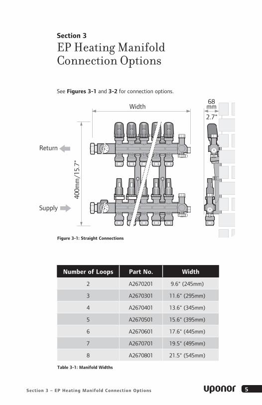
See Figures 3-1 and 3-2 for connection options.
68mm
400m
m/1
5.7"
2.7"L + 70 mm
370
435
107Width
Return
Supply
A
B
C
D
E
Figure 3-1: Straight Connections
Number of Loops Part No . Width
2 A2670201 9.6" (245mm)
3 A2670301 11.6" (295mm)
4 A2670401 13.6" (345mm)
5 A2670501 15.6" (395mm)
6 A2670601 17.6" (445mm)
7 A2670701 19.5" (495mm)
8 A2670801 21.5" (545mm)
Table 3-1: Manifold Widths

6 www.uponorpro.com6
Width + 70 mm, 2.8"A
B
C
D
E
68mm
2.7" 107mm4.2"
Return
Supply
Figure 3-2: Angle Connections
Number of Loops Part No . Width
9A2670801 + A2670001
A267000323.5" (595mm)
10A2670801 + 2 x A2670001
2 x A267000325.5" (645mm)
11A2670801 + 3 x A2670001
3 x A267000327.5" (695mm)
12A2670801 + 4 x A2670001
4 x A267000329.5" (745mm)
Table 3-2: Manifold Widths

7Section 4 – EP Heating Manifold Mounting Instructions
Section 4
EP Heating Manifold Mounting Instructions
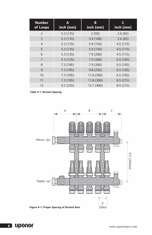
Mounting Manifold to a Wall or Cabinet1. Mount the bracket to the wall or
in a cabinet. See Table 4-1 on page 8 for proper spacing of the bracket bars.
2. Snap the manifold into the bracket. Make sure the manifold locks into position. Listen for the click.
115
1 215
8 www.uponorpro.com8
Table 4-1: Bracket Spacing
Figure 4-1: Proper Spacing of Bracket Bars
Number of Loops
Ainch (mm)
Binch (mm)
Cinch (mm)
2 5.3 (135) 2 (50) 2.6 (65)
3 5.3 (135) 3.9 (100) 2.6 (65)
4 5.3 (135) 5.9 (150) 4.5 (115)
5 5.3 (135) 5.9 (150) 4.5 (115)
6 5.3 (135) 7.9 (200) 4.5 (115)
7 5.3 (135) 7.9 (200) 6.5 (165)
8 7.3 (185) 7.9 (200) 6.5 (165)
9 7.3 (185) 9.8 (250) 6.5 (165)
10 7.3 (185) 11.8 (300) 6.5 (165)
11 7.3 (185) 11.8 (300) 8.5 (215)
12 9.3 (235) 15.7 (400) 8.5 (215)
A B C
9.5" (242mm
)
2"(50m)
Return
Supply

9Section 5 – Installing Manifold Accessories
Section 5
Installing Manifold Accessories
Note: Thread tape or similar thread sealants are not necessary for assembling the manifold accessories.
Installing Temperature GaugeWhen installing the temperature gauge into the manifold connections, ensure they snap in firmly until they click.
Installing the Elbow KitWhen mounting the Elbow Kit, follow these steps.
1. Unlock the snap lock.
2. Dismantle the connection fittings.
3. Mount the elbows.
1
2
3
10 www.uponorpro.com10
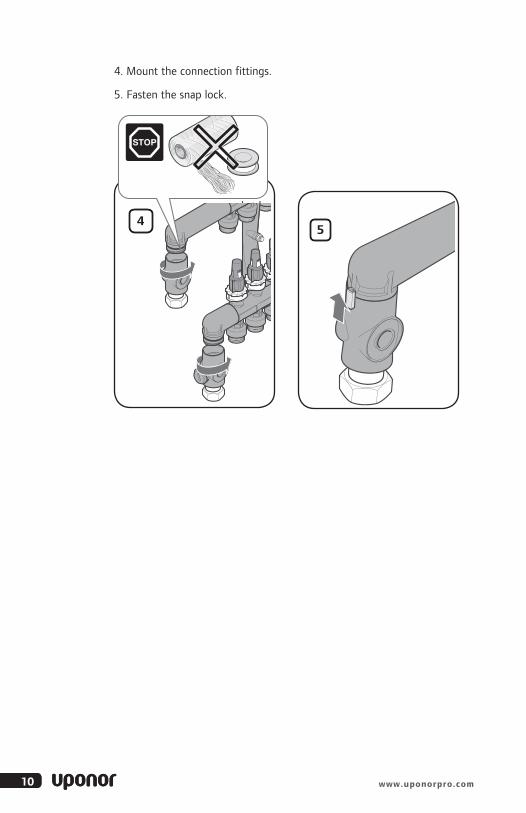
4. Mount the connection fittings.
5. Fasten the snap lock.
45
1111Section 5 – Installing Manifold Accessories
2
1.
2.
1.
2.
1.
1.
2.
2.
3
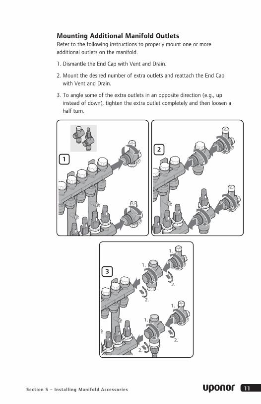
Mounting Additional Manifold OutletsRefer to the following instructions to properly mount one or more additional outlets on the manifold.
1. Dismantle the End Cap with Vent and Drain.
2. Mount the desired number of extra outlets and reattach the End Cap with Vent and Drain.
3. To angle some of the extra outlets in an opposite direction (e.g., up instead of down), tighten the extra outlet completely and then loosen a half turn.
B
1

12 www.uponorpro.com12
Section 6
Connecting Tubing to the Manifold
Connect the tubing using ProPEX or QS-style fittings. Refer to the Uponor Product Catalog for fitting information.
1. Use a PEX Cutter (E6081125, E6081128, E6081501) to square-cut the tubing perpendicular to the tubing length.
Note: Do not use a saw or similar cutting tool to cut the tubing as shavings may clog manifold valves (see Figure 6-1).
2. When making a ProPEX connection, insert a ProPEX Fitting Assembly into the manifold loop and tighten the fitting with a wrench.
Note: When making a ProPEX connection, be sure to follow the guidelines of the ProPEX Expansion Tool you are using in your application.
3. Slide the ProPEX Ring over the end of the tubing until it reaches the stop edge.
Note: Ensure the ProPEX Ring is dry and free of grease to prevent it from sliding out of place (see Figure 6-2).
4. Attach the proper size expander head to the tool and expand the tubing to the proper number of expansions (see Figure 6-3 and Table 6-1).
Figure 6-1: Square-cut the Tubing
Figure 6-2: Slide ProPEX Ring onto Tubing
Figure 6-3: Expand the Tubing
13Section 6 – Connecting Tubing to the Manifold
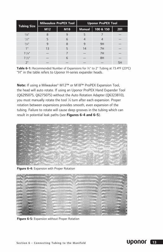
Note: If using a Milwaukee® M12™ or M18™ ProPEX Expansion Tool, the head will auto rotate. If using an Uponor ProPEX Hand Expander Tool (Q6295075, Q6275075) without the Auto Rotation Adapter (Q6323810), you must manually rotate the tool 1⁄8 turn after each expansion. Proper rotation between expansions provides smooth, even expansion of the tubing. Failure to rotate will cause deep grooves in the tubing which can result in potential leak paths (see Figures 6-4 and 6-5).
Table 6-1: Recommended Number of Expansions for 3⁄8" to 2" Tubing at 73.4ºF (23ºC) “H” in the table refers to Uponor H-series expander heads.
Tubing SizeMilwaukee ProPEX Tool Uponor ProPEX Tool
M12 M18 Manual 100 & 150 2013/8" 8 9 5 7 —1/2" 5 6 4 4 —3/4" 9 8 9 9H —
1" 13 5 14 7H —
11/4" — 7 — 7H —
11/2" — 6 — 8H —
2" — — — — 5H
Figure 6-4: Expansion with Proper Rotation
Figure 6-5: Expansion without Proper Rotation
14 www.uponorpro.com
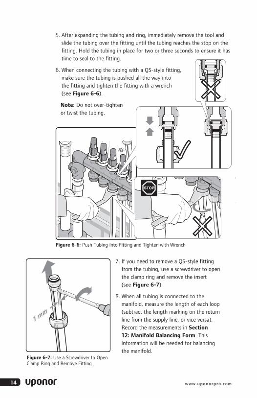
5. After expanding the tubing and ring, immediately remove the tool and slide the tubing over the fitting until the tubing reaches the stop on the fitting. Hold the tubing in place for two or three seconds to ensure it has time to seal to the fitting.
6. When connecting the tubing with a QS-style fitting, make sure the tubing is pushed all the way into the fitting and tighten the fitting with a wrench (see Figure 6-6).
Note: Do not over-tighten or twist the tubing.
Uponor GmbHHans-Böckler-Ring 4122851 NorderstedtGermany
T +49 (0)40 30 986-0F +49 (0)40 30 986-433W www.heizen-kuehlen.uponor.deE [email protected]
End-MeterzahlEnd no. of metersMeteraanduiding eindeIndication des mètresMetraggio finaleKonečný počet metrů
Effektive RohrlängeEffective pipe lengthEffectieve buislengteLongueurs de tuyauxeffectifLunghezza effettivatubazioneEfektivní délkatrubky
Anfangs-MeterzahlStart no. of metersMeteraanduiding beginIndication des mètresMetraggio inizialePočáteční počet metrů
Ventil-Einstellung/WassermengeValve setting/Quantity of waterVentielvoorinstelling/Hoeveelheid waterRéglage des vannes/Quantité d’eauTaratura valvola/Quantità di acquaNastavení ventilu/množství vody
692
617
75
Uponor
0692
0617
DemontageDismoutingDemontageDémontageSmontaggiodemontáž
PlanungPlanningPlanningPlanningPlanificazioneplánování
Formblatt zur Ermittlung der tatsächlichen Heizkreisrohrlängen undNachrechnung der VentileinstellungForm for determining the actual pipe length of the heating circuit and checking of the valve setting• Werkblad voor berekening van de werkelijke buislengte per groep na montage en het narekenen van deventielvoorinstellingen • Tableau de référence pour la calculation des longueurs de tuyaux réelles par circuit,après le montage et la recalculation des préréglages des vannes de régulation • Scheda per segnare l’esattalunghezza di ogni circuito per il calcolo della taratura • Formulář pro stanovení skutečných délek trubektopných okruhů a kontroly nastavení ventilů
Nach Eintragung der Anfangs- und End-Meterzahl ist dieses Formblatt der Planung zu übergeben.
Fill in the start and end no. of meters and hand this form over to the planning department.
Na het invullen van de meterstand (op de buis) bij het begin en einde van de groep dient deze informatie aan dewerkvoorbereiding afgeven te worden.
Après le remplissage des mètres de tuyaux (au début et à la fin d'un circuit), cette information doitêtre remis au bureau d'étude.
1 mm
1
20
1.
2.
2
7. If you need to remove a QS-style fitting from the tubing, use a screwdriver to open the clamp ring and remove the insert (see Figure 6-7).
8. When all tubing is connected to the manifold, measure the length of each loop (subtract the length marking on the return line from the supply line, or vice versa). Record the measurements in Section 12: Manifold Balancing Form. This information will be needed for balancing the manifold.
Uponor GmbHHans-Böckler-Ring 4122851 NorderstedtGermany
T +49 (0)40 30 986-0F +49 (0)40 30 986-433W www.heizen-kuehlen.uponor.deE [email protected]
End-MeterzahlEnd no. of metersMeteraanduiding eindeIndication des mètresMetraggio finaleKonečný počet metrů
Effektive RohrlängeEffective pipe lengthEffectieve buislengteLongueurs de tuyauxeffectifLunghezza effettivatubazioneEfektivní délkatrubky
Anfangs-MeterzahlStart no. of metersMeteraanduiding beginIndication des mètresMetraggio inizialePočáteční počet metrů
Ventil-Einstellung/WassermengeValve setting/Quantity of waterVentielvoorinstelling/Hoeveelheid waterRéglage des vannes/Quantité d’eauTaratura valvola/Quantità di acquaNastavení ventilu/množství vody
692
617
75
Uponor
0692
0617 Planung
PlanningPlanningPlanningPlanificazioneplánování
Formblatt zur Ermittlung der tatsächlichen Heizkreisrohrlängen undNachrechnung der VentileinstellungForm for determining the actual pipe length of the heating circuit and checking of the valve setting• Werkblad voor berekening van de werkelijke buislengte per groep na montage en het narekenen van deventielvoorinstellingen • Tableau de référence pour la calculation des longueurs de tuyaux réelles par circuit,après le montage et la recalculation des préréglages des vannes de régulation • Scheda per segnare l’esattalunghezza di ogni circuito per il calcolo della taratura • Formulář pro stanovení skutečných délek trubektopných okruhů a kontroly nastavení ventilů
Nach Eintragung der Anfangs- und End-Meterzahl ist dieses Formblatt der Planung zu übergeben.
Fill in the start and end no. of meters and hand this form over to the planning department.
Na het invullen van de meterstand (op de buis) bij het begin en einde van de groep dient deze informatie aan dewerkvoorbereiding afgeven te worden.
Après le remplissage des mètres de tuyaux (au début et à la fin d'un circuit), cette information doitêtre remis au bureau d'étude.
SW 30
1 mm
1
20
3
Figure 6-6: Push Tubing Into Fitting and Tighten with Wrench
Figure 6-7: Use a Screwdriver to Open Clamp Ring and Remove Fitting

15EP Heating Manifold Installation Guide
Section 7
Filling and Purging the Manifold
To ensure the manifold provides enough water for superior performance, fill and purge the system at the boiler or at the manifold.
If you choose to fill and purge at the manifold, see the following instructions.
1. Connect a water hose from a faucet to the fill valve on the supply manifold cap.
2. Connect a separate drain hose to the cap on the return manifold and place the other end into a large bucket or into a drain.
3. Close all valves on the manifold (both supply and return manifold), as well as the Supply and Return Ball Valve (A2631252) installed on the supply and return lines.
4. Open the valves for the first loop on the manifold.
open
open
max. 72 psi
close
close
close
open
open
1
2
4
3 close
open
16 www.uponorpro.com
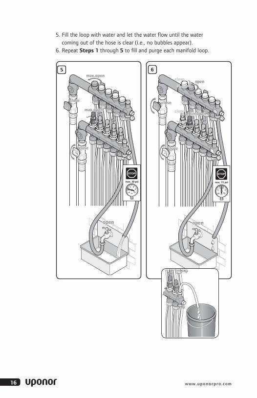
5. Fill the loop with water and let the water flow until the water coming out of the hose is clear (i.e., no bubbles appear).
6. Repeat Steps 1 through 5 to fill and purge each manifold loop.
open
max.open
close
close
5
max. 30 psi
max.open
open
open
max. 72 psi
close
close
close
6
close min.open

17EP Heating Manifold Installation Guide
Section 8
Pressure Testing
To ensure the system is installed correctly and operating properly, it is important to pressure test the system. There are several options to pressure test a system, including air and water. However, air provides a much more rigorous test.
1. To ensure all valves are working accurately, open and close all valves twice. Make sure all manifold isolation and flow valves are open.
Note: Manifold Supply and Return Ball Valves should be closed during the pressure test procedure.
2. Connect the Uponor Manifold Pressure Test Kit (E6122000) or other pressure test device. Uponor recommends a test pressure of 3 times the operating pressure, or at least 40 psi.
Note: Maximum pressure when testing with air should not exceed 120 psi.
3. Visually check for leaking and monitor the pressure for the duration specified by local code. (A typical pressure test can range from 2 to 24 hours.)
4. If there is no reduction in pressure, the system is regarded as sealed.
5. After completing the pressure test, set the operating pressure.
After 2 hours,
Max 87 psi
check for leakage.
open
2 hours max. 87 psi
2
1

18 www.uponorpro.com
Section 9
Adjusting Manifold Valves
Balance the manifold system to ensure superior performance.
1. Use the manifold flow meters to balance the system.
2. Make sure the system is in operation and water is flowing through the manifold.
3. Turn the balancing valve until the desired flow in the loop is obtained.
Note: Visually check the flow meter window to ensure proper flow.
4. Lift and turn the adjustment ring to the set valve position and push it back down into the locked position.
max open
6mm3 mm 5x
5
close
max close
3 4
4
close
Raum-Heizkreis-DatenRoom heating circuit dataRuimte- en verwarminggroepsgegevensDonnées des pièces - circuits de chauffageDati circuito riscaldamento locale
Raum-NrRoom No.Ruimte-Nr
N° de la pièceNum. locale
Heizkreis-NrHeating circuit No.
Verwarmingsgroep nrN° du circuits de
chauffageNum. circuito
riscaldamento locale
Uponor FußbodenheizungsberechnungUponor floor heating calculationsUponor vloerverwarmingsberekeningCalculation du chauffage par le sol UponorCalcolo riscaldamento a pannelli radianti Uponor
11234
12345
485
11
4,5
VentileinstellungValve adjustment
VentielvoorinstellingRéglage de la vanneTartura della valvola
485
111,5
WassermengeQuantity of waterHoeveelheid water
Quantité d’eauQuantità di acqua
l/min
1 2 3
RohrnetzberechnungPipe system calculationsLeidingnetberekeningCalculation des circuits de tuyau
Strang 1Riser pipe 1Strang 1Conduit principal 1
Verteiler 1Distributor 1Verdeler 1Collecteur 1
Verteiler 2Distributor 2Verdeler 2Collecteur 2
Strang 2Riser pipe 2Strang 2Conduit principal 2
Verteiler 1Distributor 1Verdeler 1Collecteur 1
Verteiler 2Distributor 2Verdeler 2Collecteur 2
Ventileinstellung
Valve adjustmentVentielvoorinstelling
8
5
Ventileinstellung
Valve adjustmentVentielvoorinstelling
8
5
5
Massenstrom m in [kg/h]
Dru
ckve
rlus
t Δ
p in
[mba
r]
10
20
30
40
50
60
80
100
200
3
2,5
2
5 6
4
8
[kP
a]
300
400
500
1
2
3
4
5
6
8
10
20
30
40
50
300200 500 1000 2000 3000100
7
Medium: WasserMedium: Wasser
2
3
1
2
1

19EP Heating Manifold Installation Guide
Section 10
Manifold Maintenance
The EP Heating Manifold does not require a maintenance schedule. However, Uponor recommends checking system components regularly.
Use a soft, dry cloth to clean the manifold as needed.
Do not use a damp cloth or cleaning agents.
20 www.uponorpro.com
Section 11
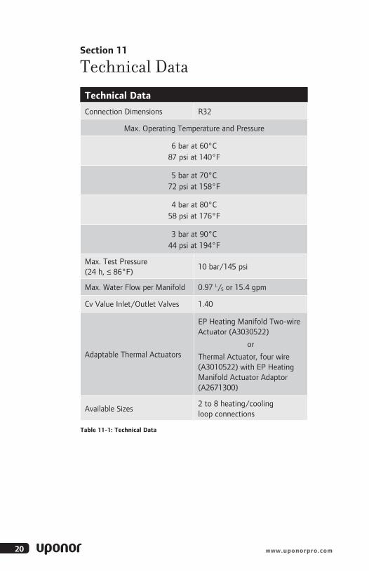
Technical Data
Technical Data
Connection Dimensions R32
Max. Operating Temperature and Pressure
6 bar at 60°C 87 psi at 140°F
5 bar at 70°C 72 psi at 158°F
4 bar at 80°C 58 psi at 176°F
3 bar at 90°C 44 psi at 194°F
Max. Test Pressure (24 h, ≤ 86°F)
10 bar/145 psi
Max. Water Flow per Manifold 0.97 L/S or 15.4 gpm
Cv Value Inlet/Outlet Valves 1.40
Adaptable Thermal Actuators
EP Heating Manifold Two-wire Actuator (A3030522)
or
Thermal Actuator, four wire (A3010522) with EP Heating Manifold Actuator Adaptor (A2671300)
Available Sizes2 to 8 heating/cooling loop connections
Table 11-1: Technical Data

21EP Heating Manifold Installation Guide
ChemicalsDo not use the chemicals outlined in Table 11-2 with the EP Heating Manifold.
Chemical Common Uses
Acetaldehyde Disinfectants, Air Deodorizers, Lacquers/Varnishes
Acetone Varnish Remover, General Solvent
Acids Any situation requiring a high concentration of acidic chemicals
Aluminum Salts of Mineral AcidsAmmonia Cleansers, Bleach, FertilizersAmmonium Chloride Adhesives, ShampooAmmonium Hydroxide Cleansers, Bleachn-Amyl Acetate Paint and Lacquer RemoversBarium Chloride Dyes, PesticidesBromine Disinfectants, Dyes, Fuel Additives, Pesticidesn-Butanol Paint ThinnersCalcium Chloride Antifreeze, Fire ExtinguishersCalcium Thiocynate Water Treatment (pool)Chlorine (Concentrated) Water TreatmentChloroform Fire Extinguishers, Dyes, PesticidesChlorox Bleach
m-Cresol Disinfectants, Insecticides, Photography Developers
Ethylene Dibromide Insecticides, Fuel AdditivesEthylene Glycol Antifreeze/coolantHexafluoroisopropanol Electronics CleansersHydrogen Peroxide DisinfectantsHydrogen Sulfide Fuels
Methylene Chloride Paint Removers, Degreasers, Aerosol Foam Sprays, Pesticides
Phenol Disinfectants, HerbicidesPotassium Carbonate Adhesives, Bleach, CleansersPotassium Permanganate Disinfectants, Water Treatment (Pools)Potassium Thiocyanate Dyes, Photography DevelopersSodium Hydroxide Paint Removers, Cleansers, Lye, Drain CleanersSodium Hypochlorite Bleach, DisinfectantsStannic Chloride Dyes, SoapsStannic Sulfate Gypsum, Lacquer/VarnishSulfur Dioxide BleachTetrafluoropropane Refrigerants, Lubricants
Table 11-2: Chemicals Inappropriate with EP Heating Manifold
22 www.uponorpro.com
Section 12
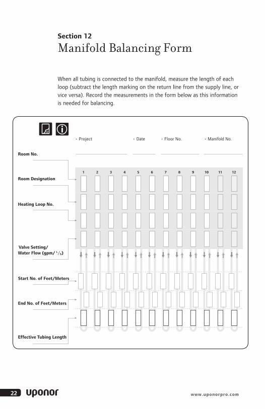
Manifold Balancing Form
When all tubing is connected to the manifold, measure the length of each loop (subtract the length marking on the return line from the supply line, or vice versa). Record the measurements in the form below as this information is needed for balancing.
• Project
Room No.
• Floor No. • Date • Manifold No.
End No. of Feet/Meters
Effective Tubing Length
Room Designation
Start No. of Feet/Meters
1 2 3 4 5 6 7 8 9 10 11 12
12
Heating Loop No.
Valve Setting/Water Flow (gpm/ L/S)

23EP Heating Manifold Installation Guide
Notes

Uponor, Inc . 5925 148th Street West Apple Valley, MN 55124 USA Tel: 800.321.4739 Fax: 952.891.2008
Uponor Ltd . 2000 Argentia Rd., Plaza 1, Ste. 200 Mississauga, ON L5N 1W1 CANADA Tel: 888.994.7726 Fax: 800.638.9517
EP_H
eatM
fld_I
nsG
_H45
3_08
13, C
opyr
ight
© 2
013
Upo
nor.
Prin
ted
in t
he U
nite
d St
ates
MK
T100
18-A
A
www .uponorpro .com