eo-150 ventilator - sapio life · a ventilator dependent patient should always be monitored by...
TRANSCRIPT

100-23 rev B
EO-150 Ventilator
User Guide

2
Contents Introduction ............................................................................................................................................ 5
Indications for use ............................................................................................................................... 5
Definitions ........................................................................................................................................... 5
General warnings and cautions .......................................................................................................... 5
Chapter One – Description of the EO-150 ventilator ............................................................................. 7
Front Panel .......................................................................................................................................... 7
Rear Panel ........................................................................................................................................... 7
Rear view of ventilator without housing ........................................................................................... 8
Menu Bar / Keyboard .......................................................................................................................... 9
Symbols Table ..................................................................................................................................... 9
Chapter Two – Operating Instructions for the EO-150 ventilator ........................................................ 11
Set Up Test ........................................................................................................................................ 11
Turning on the device ....................................................................................................................... 12
Turning off the device ....................................................................................................................... 12
Starting and Stopping ventilation ..................................................................................................... 12
Switching the touch screen on and off and using screen saver mode ............................................. 13
The Home Screen .............................................................................................................................. 14
Navigating the Patient Screen and Menu ......................................................................................... 15
Alarms log ......................................................................................................................................... 16
Accessing and using the Clinical Menu ............................................................................................ 16
Presets ............................................................................................................................................... 17
Presets Configuration Screen Access: ............................................................................................... 17
Patient Configuration Menu ............................................................................................................. 18
Changing ventilation mode ............................................................................................................... 19
Other screens: ................................................................................................................................... 20
Chapter 3: Installing Patient Circuit Configurations ............................................................................. 23
Patient Circuit options ...................................................................................................................... 23
Calibration ......................................................................................................................................... 24
Starting calibration ........................................................................................................................... 24
Connecting circuit configurations ..................................................................................................... 26
Accessories Compatible with EO-150 .............................................................................................. 29
Attaching patient circuit accessories ................................................................................................ 29
Attaching an antibacterial filter ........................................................................................................ 30
3
Attaching a humidifier ...................................................................................................................... 30
Attaching oxygen .............................................................................................................................. 31
Attaching an FiO2 sensor ................................................................................................................... 32
Attaching a pulse oximeter ............................................................................................................... 32
Attaching a remote alarm ................................................................................................................. 33
Power Connections .......................................................................................................................... 33
Connecting to mains power .............................................................................................................. 33
Running the ventilator on internal battery ....................................................................................... 34
Battery run time ................................................................................................................................ 35
Storing and recharging ...................................................................................................................... 35
Prepare the battery for long-term storage: ...................................................................................... 35
Connecting to an external DC power source .................................................................................... 36
Travelling with the EOVE Ventilator, the Click-and-Go system . ...................................................... 36
Using the Nomad Bag (no docking station) ...................................................................................... 37
Using the Transport bag .................................................................................................................... 38
Chapter 4: Alarms ................................................................................................................................. 38
When an alarm is activated .............................................................................................................. 38
Viewing active alarms ....................................................................................................................... 39
Alarm priority .................................................................................................................................... 40
Troubleshooting Alarms .................................................................................................................... 40
Data management ............................................................................................................................ 42
Chapter 5: Routine Cleaning and Maintenance .................................................................................... 42
Servicing ............................................................................................................................................ 44
Maintenance Timetable .................................................................................................................... 44
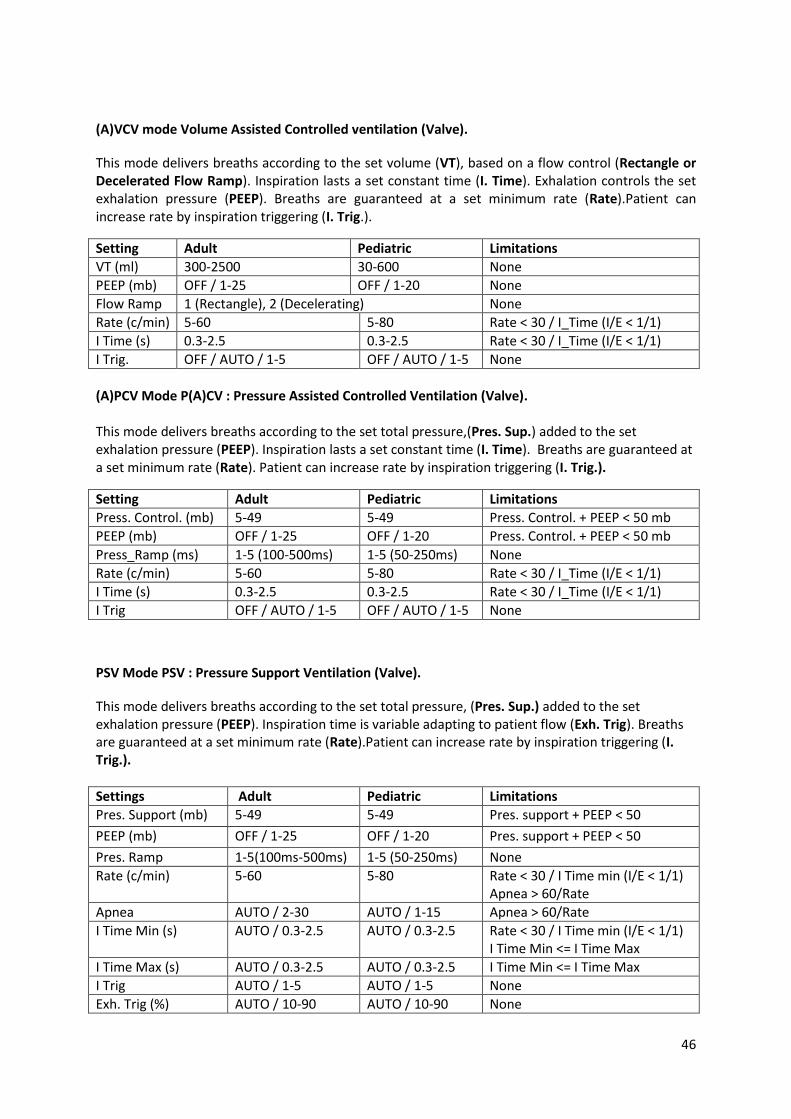
Chapter 6: Device information .............................................................................................................. 45
Technical specifications .................................................................................................................... 45
Physical Specifications: ..................................................................................................................... 45
Ventilation Specifications ................................................................................................................. 45
Monitored Parameter Specifications: ............................................................................................... 50
Power specifications : ....................................................................................................................... 51
Environmental Specifications............................................................................................................ 52
Breathing system Specifications ....................................................................................................... 52
Software versions.............................................................................................................................. 52
Guidance and Manufacturer’s Declaration Electromagnetic Emissions & Immunity....................... 52

4
Standards compliance: ...................................................................................................................... 54
Training and support ......................................................................................................................... 55
Limited warranty ............................................................................................................................... 55
Appendix A: Definitions .................................................................................................................... 56
Ventilation Setting Definitions: ......................................................................................................... 56
Measured and calculated parameter definitions: ............................................................................ 57

5
Introduction The EOVE EO-150 ventilator provides mechanical ventilation for ventilator dependent and non-dependent patients. It provides pressure and volume ventilation for adults and pediatric patients as prescribed by an attending doctor. This User Guide is designed for a patient or caregiver. It does not contain all the information included in the Clinical Guide.
Indications for use The EO-150 ventilator device provides continuous or intermittent ventilation support for pediatric and adult patients weighing at least 3.5kg (8lbs) who require mechanical ventilation. The EO device is intended to be used in home, institution, hospital and portable environments for both invasive and non-invasive ventilation.
CAUTION E0-150 ventilator is not for use with anaesthetic gases, and is not intended for
use as an emergency transport ventilator
.
Definitions
WARNING Indicates a condition that may endanger the patient or the device operator
CAUTION Indicates a condition that may damage the device or equipment
Note: Advice that makes operation of the device more convenient or efficient
General warnings and cautions
WARNING
Read and understand the entire manual before using the EO-150 ventilator
The EO-150 ventilator is a restricted medical device intended for use by qualified trained personnel, under the direction of a doctor.
Use the EO-150 ventilator only as directed by a doctor or healthcare provider.
Information in this manual does not supersede instructions given by the prescribing doctor.
Install and configure the EO-150 ventilator in accordance with the instructions given in this guide. Non-specialist operators or institutions encountering problems with set-up, operation or maintenance should immediately contact their EOVE representative.
An alternative means of ventilation should always be available for ventilator-dependent patients. Failure to do tbis may result in patient injury or death.
A ventilator dependent patient should always be monitored by trained personnel.
Verify the effectiveness of ventilation and alarms before connecting a patient to the ventilator.
Handle the EO-150 ventilator and AC power supply with care during and after use especially if ambient temperatures are high as some surfaces may become hot. Do not leave the EO-150 ventilator in direct contact with the patient for extended periods of time.
The EO-150 should be kept out of reach of children and domestic animals to ensure their safety and the safety of the patient and to avoid damage to the ventilator and the accessories.
The battery and all machine parts of the ventilator should be disposed of appropriately,

6
following correct regulations for waste management in order to minimize the risk for the environment. They should not be disposed of in household waste.
CAUTION
The EO-150 ventilator is not intended for use as an emergency transport ventilator.
Do not expose the EO-150 ventilator to excessive force, do not shake or drop.
If the ventilator or its power supply are dropped or mishandled, immediately discontinue use and contact your EOVE representative.
Repairs and servicing should only be carried out by an authorized EOVE service representative or a qualified and certified Service representative.
The airflow for breathing produced by the ventilator can be higher than the temperature of the room by up to 6°C. Exercise caution if the ambient air in the room exceeds 35ºC.

7
Chapter One – Description of the EO-150 ventilator
Front Panel
1. Display screen 4. EO device housing unit
2. Ventilation module 5. Inspiratory / Circuit Port
3. Proximal pressure, valve, and proximal flow connectors 6. Menu bar / keyboard
Rear Panel
6 2
3
1
e
n
t
i
l
a
t
i
o
n
m
o
d
u
l
e
1
4
5
6
2
3
4
3
5
4
3 4
3
3
6
4
3 4
3
3
1

8
1. Air inlet and hypoallergenic filter 4. O2 input
2. DC Power connector 5 FiO2 / SpO2 connector
3. STANDBY Button 6. Remote Alarm connector
Rear view of ventilator without housing
1. USB port
2. DC Car charger connection
3. Connection to outer housing
1
2
3
9
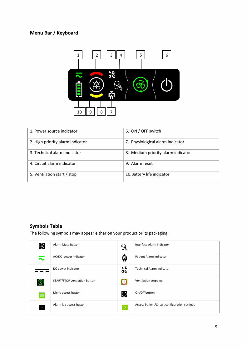
Menu Bar / Keyboard
1. Power source indicator 6. ON / OFF switch
2. High priority alarm indicator 7. Physiological alarm indicator
3. Technical alarm indicator 8. Medium priority alarm indicator
4. Circuit alarm indicator 9. Alarm reset
5. Ventilation start / stop 10.Battery life indicator
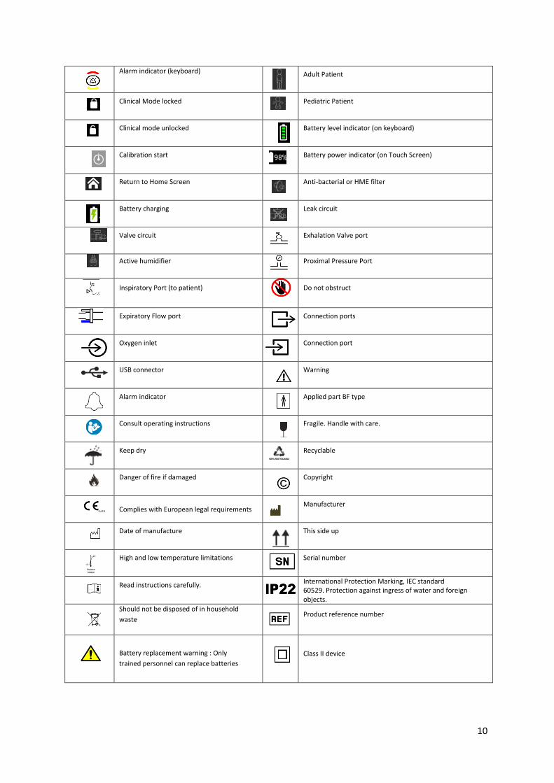
Symbols Table
The following symbols may appear either on your product or its packaging.
Alarm Mute Button Interface Alarm indicator
AC/DC power indicator Patient Alarm indicator
DC power indicator Technical Alarm indicator
START/STOP ventilation button Ventilation stopping
Menu access button On/Off button
Alarm log access button Access Patient/Circuit configuration settings
1 2 3 4 5
4
6
7 8 9 10
10
Alarm indicator (keyboard) Adult Patient
Clinical Mode locked Pediatric Patient
Clinical mode unlocked Battery level indicator (on keyboard)
Calibration start Battery power indicator (on Touch Screen)
Return to Home Screen Anti-bacterial or HME filter
Battery charging Leak circuit
Valve circuit Exhalation Valve port
Active humidifier Proximal Pressure Port
Inspiratory Port (to patient)
Do not obstruct
Expiratory Flow port Connection ports
Oxygen inlet Connection port
USB connector Warning
Alarm indicator Applied part BF type
Consult operating instructions Fragile. Handle with care.
Keep dry Recyclable
Danger of fire if damaged Copyright
Complies with European legal requirements
Manufacturer
Date of manufacture This side up
High and low temperature limitations Serial number
Read instructions carefully. International Protection Marking, IEC standard 60529. Protection against ingress of water and foreign objects.
Should not be disposed of in household
waste Product reference number
Battery replacement warning : Only
trained personnel can replace batteries
Class II device
11
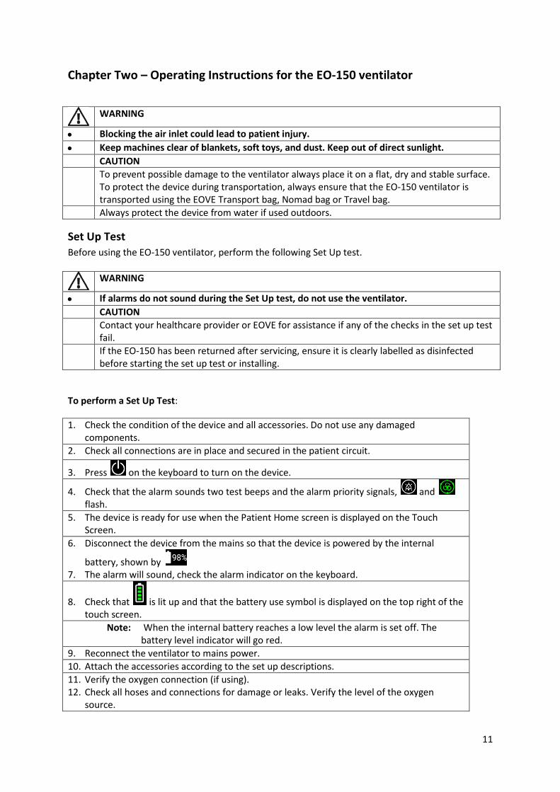
Chapter Two – Operating Instructions for the EO-150 ventilator
WARNING
Blocking the air inlet could lead to patient injury.
Keep machines clear of blankets, soft toys, and dust. Keep out of direct sunlight.
CAUTION
To prevent possible damage to the ventilator always place it on a flat, dry and stable surface. To protect the device during transportation, always ensure that the EO-150 ventilator is transported using the EOVE Transport bag, Nomad bag or Travel bag.
Always protect the device from water if used outdoors.
Set Up Test
Before using the EO-150 ventilator, perform the following Set Up test.
WARNING
If alarms do not sound during the Set Up test, do not use the ventilator.
CAUTION
Contact your healthcare provider or EOVE for assistance if any of the checks in the set up test fail.
If the EO-150 has been returned after servicing, ensure it is clearly labelled as disinfected before starting the set up test or installing.
To perform a Set Up Test:
1. Check the condition of the device and all accessories. Do not use any damaged components.
2. Check all connections are in place and secured in the patient circuit.
3. Press on the keyboard to turn on the device.
4. Check that the alarm sounds two test beeps and the alarm priority signals, and flash.
5. The device is ready for use when the Patient Home screen is displayed on the Touch Screen.
6. Disconnect the device from the mains so that the device is powered by the internal
battery, shown by 7. The alarm will sound, check the alarm indicator on the keyboard.
8. Check that is lit up and that the battery use symbol is displayed on the top right of the touch screen.
Note: When the internal battery reaches a low level the alarm is set off. The battery level indicator will go red.
9. Reconnect the ventilator to mains power.
10. Attach the accessories according to the set up descriptions.
11. Verify the oxygen connection (if using). 12. Check all hoses and connections for damage or leaks. Verify the level of the oxygen
source.

12
Turning on the device
Ensure the device has been charged prior to use or connect to AC power or DC connector inlet.
1. Insert AC connector into power inlet.
2. Turn the screw lock clockwise to secure.
3. Press on front panel keyboard to power on the ventilator. The Home Screen will be displayed.
Turning off the device
1. Press and hold until the ALARM key flashes.
2. Press to confirm.
3. The ventilator turns OFF.
Starting and Stopping ventilation Ventilation can be started and stopped from either the touch screen or from the keyboard. Various preset ventilation treatments may be installed on the device by your clinician to ensure the best therapy for you. Use these presets according to the instructions provided by the clinician.
To START ventilation using the menu bar:
1. Press on the Keyboard
2. Ventilation starts.
To START ventilation using the Touch Screen:
1. Press on the touch screen 2. Ventilation starts.
To STOP ventilation using the Keyboard:
1. Press and hold until the alarm key flashes.
2. Press to confirm.
3. Ventilation stops.
To STOP ventilation using the Touch Screen:
1. Press and hold until:
flashes
The red line around the START/STOP key completes a full circle.
2. The pop-up on the screen will ask you to validate your choice. Press to confirm.
3. Ventilation stops.

13
CAUTION
The EO-150 ventilator cannot be powered off during ventilation
Unplugging from mains power does not power off the device. It will continue to run on the internal battery.
The device must be turned off manually before disconnecting from AC power for any extended period of time. Failure to do so may result in battery depletion and the alarms may be activated
Switching the touch screen on and off and using screen saver mode
The STANDBY button on the docking station can also be used to power on the Touch Screen by pressing it for a few seconds until the screen lights up (see image below).
To switch off the touch screen, press the button for a few seconds and follow the prompts which appear on the screen.
To put the touch screen into screensaver mode, press the STANDBY button at the back of the docking station.
NOTE: To ensure the screen is in screensaver mode, simply touch the screen. In Sleep mode the screen will remain black.
1 1 1
STANDBY button
14
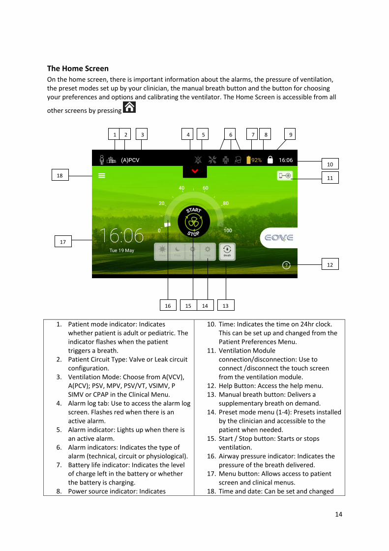
The Home Screen On the home screen, there is important information about the alarms, the pressure of ventilation, the preset modes set up by your clinician, the manual breath button and the button for choosing your preferences and options and calibrating the ventilator. The Home Screen is accessible from all
other screens by pressing
1. Patient mode indicator: Indicates whether patient is adult or pediatric. The indicator flashes when the patient triggers a breath.
2. Patient Circuit Type: Valve or Leak circuit configuration.
3. Ventilation Mode: Choose from A(VCV), A(PCV); PSV, MPV, PSV/VT, VSIMV, P SIMV or CPAP in the Clinical Menu.
4. Alarm log tab: Use to access the alarm log screen. Flashes red when there is an active alarm.
5. Alarm indicator: Lights up when there is an active alarm.
6. Alarm indicators: Indicates the type of alarm (technical, circuit or physiological).
7. Battery life indicator: Indicates the level of charge left in the battery or whether the battery is charging.
8. Power source indicator: Indicates
10. Time: Indicates the time on 24hr clock. This can be set up and changed from the Patient Preferences Menu.
11. Ventilation Module connection/disconnection: Use to connect /disconnect the touch screen from the ventilation module.
12. Help Button: Access the help menu. 13. Manual breath button: Delivers a
supplementary breath on demand. 14. Preset mode menu (1-4): Presets installed
by the clinician and accessible to the patient when needed.
15. Start / Stop button: Starts or stops ventilation.
16. Airway pressure indicator: Indicates the pressure of the breath delivered.
17. Menu button: Allows access to patient screen and clinical menus.
18. Time and date: Can be set and changed
1 2 3 4 5 7 8 9
10
12
13 14 15 16
6
17
18 11
15
whether the device is operating on mains power (AC) or DC power.
9. Clinical mode: Indicates whether the clinical menu is locked or unlocked.
from the Patient Preferences Menu.
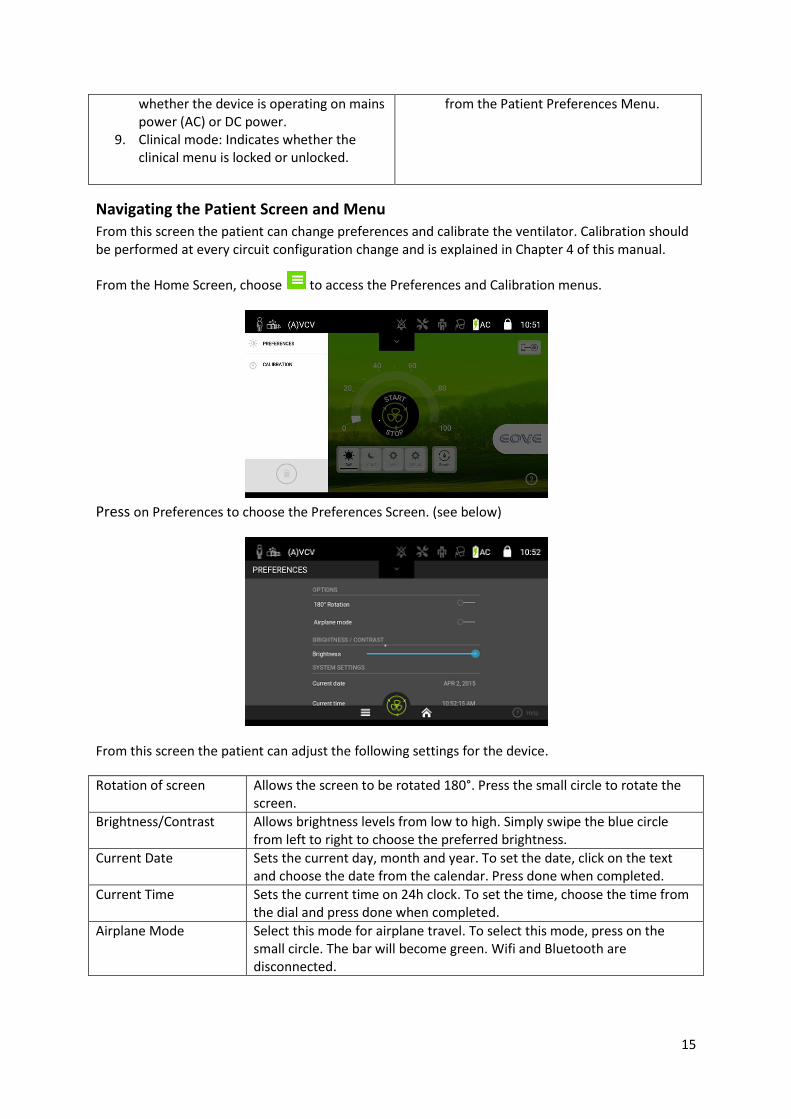
Navigating the Patient Screen and Menu
From this screen the patient can change preferences and calibrate the ventilator. Calibration should be performed at every circuit configuration change and is explained in Chapter 4 of this manual.
From the Home Screen, choose to access the Preferences and Calibration menus.
Press on Preferences to choose the Preferences Screen. (see below)
From this screen the patient can adjust the following settings for the device.
Rotation of screen Allows the screen to be rotated 180°. Press the small circle to rotate the screen.
Brightness/Contrast Allows brightness levels from low to high. Simply swipe the blue circle from left to right to choose the preferred brightness.
Current Date Sets the current day, month and year. To set the date, click on the text and choose the date from the calendar. Press done when completed.
Current Time Sets the current time on 24h clock. To set the time, choose the time from the dial and press done when completed.
Airplane Mode Select this mode for airplane travel. To select this mode, press on the small circle. The bar will become green. Wifi and Bluetooth are disconnected.

16
Alarms log
To access the reports of alarms for the ventilator, from the Home Screen, touch or swipe down
to access alarm log.
On the screen you will see the list of alarms in chronological order.
See Chapter 4 for more detailed information on alarms and how to respond to them.
Accessing and using the Clinical Menu
NOTE: Do not access clinical mode (unlocked mode ) unless directed by a physician.
To access the Clinical Menu
1. Choose it from the scroll-down list.
2. Hold down the lock button, until it becomes red. The clinical screens can now be accessed.

17
Presets
The EO-Series ventilator can store up to four different ventilation presets. Presets can be configured by your clinician to provide personalized alternative treatment options. These preset configurations allow for different treatments according to the time of day or the activity being undertaken by the patient. The presets can have different circuit, ventilation and alarm settings. It is possible to change
between presets during ventilation.
NOTE: If more than one preset has been set up, follow the instructions of your clinician for when and how they should be used.
It is not possible to switch from one patient configuration (adult to pediatric) during ventilation. Each Preset saves the initial configuration and calibration data when it is set up. Always perform a calibration before saving Presets.
Presets Configuration Screen Access:
Press on the scroll-down menu button, , and choose Presets or choose ‘Save As Preset’ from the top right of all clinical screens.

18
From the Presets screen below, you can activate or name the presets and save the active mode.
.
Patient Configuration Menu
NOTE: The Clinician Screen can only be accessed when the Clinical menu is unlocked. This should only be unlocked by a doctor or health care provider or at their request.
Access the Patient/ Circuit configuration menu by pressing
1 2
3
4
5 6
7
8

19
From this screen, you can change the settings shown below and perform a calibration. Simply press on the square of the setting you wish to change and it will be outlined in green.
1. Pathology: BPCO, SOHV, Steinert, NeuroMuscular.
5.Add accessories: Humidifier and Bacterial Filter.
2. Life support: <12hours, >12 hours, >16 hours, or life support.
6. Leak Level: Between 10 and 100 l/min
3. Sensors: SP02, FI02, C02. 7. Circuit Type: Valve or Leak.
4. Perform Calibration: To be done after every circuit configuration change.
8. Patient Type: Adult or pediatric/child.
Changing ventilation mode:
From the clinical menu, select the mode bar on the upper left of the screen.
Scroll down to choose the required mode. Modes that are in grey are not accessible.

20
Validate your choice of mode, and ventilation will start on your device.
Other screens:
Events Log Screen
This screen shows all alarms, setting changes, configuration changes and any power on/off events. Up to 5000 events can be saved and consulted.
Monitorings Screen
This screen shows patient physiological data

21
Wave Forms Screens
1. Flow rate in red 4.Screen selection: Pressure and volume screen
2.Pressure rate in blue 5.Screen selection: Real time loop screen
3.Screen selection: Pressure and flow screen
This screen reports the patient data and is updated with every breath. The time scale adapts to the
patient’s respiration rate every minute. This screen shows 3 ventilation cycles in pressure and flow.
This screen shows the pressure in blue and the volume in green.
This screen shows the real-time loop data for Flow and pressure.
1
2
3
4
5

22
Alarms Settings Screen
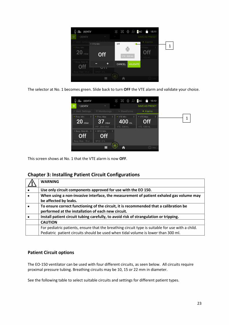
This screen allows your caregiver or doctor to set the parameters for the alarms.
This screen shows the Patient Monitoring values which correspond to the Alarms. Select the value you wish to change.
On this screen, adjust the value with the Plus and Minus signs (N°1 ) or slide the selector (No. 2) to turn ON (it will become green) or OFF.
2
1
23
The selector at No. 1 becomes green. Slide back to turn OFF the VTE alarm and validate your choice.
This screen shows at No. 1 that the VTE alarm is now OFF.
Chapter 3: Installing Patient Circuit Configurations
WARNING
Use only circuit components approved for use with the EO 150.
When using a non-invasive interface, the measurement of patient exhaled gas volume may be affected by leaks.
To ensure correct functioning of the circuit, it is recommended that a calibration be performed at the installation of each new circuit.
Install patient circuit tubing carefully, to avoid risk of strangulation or tripping.
CAUTION
For pediatric patients, ensure that the breathing circuit type is suitable for use with a child. Pediatric patient circuits should be used when tidal volume is lower than 300 ml.
Patient Circuit options
The EO-150 ventilator can be used with four different circuits, as seen below. All circuits require proximal pressure tubing. Breathing circuits may be 10, 15 or 22 mm in diameter.
See the following table to select suitable circuits and settings for different patient types.
1
1

24
30 ml to 300 ml Paediatric 10 mm or 15 mm
> 300 ml Adult 15 mm or 22 mm
The four types of circuits used by the EOVE ventilator can be found in the following table:
Single Limb with valve Single limb circuit with expiratory valve (expiratory valve integrated into the circuit)
Single Limb with valve + proximal flow
Single limb circuit with expiratory valve and proximal flow sensor
Single limb with leak Single limb circuit with intentional leak
Double Limb (with adapter) Double limb circuit (expiratory valve integrated into the adapter)
CAUTION
To ensure accurate performance, a circuit calibration is recommended at every change of circuit configuration.
The blue proximal flow sensor tube must be connected at the side closest to the patient and according to the symbols on the ventilator ports. If connected in the wrong way, no VTE will be displayed.
Do not connect patient interfaces before starting the calibration. Patient interfaces include any components such as catheter mount, mask, tracheostomy tube or intentional calibrated leak.
Calibration
The EOVE ventilator can be calibrated in order to allow a wide range of circuit configurations and accessories. This calibration verifies the compliance characteristics of the circuit configuration chosen.
Starting calibration: 1. From either the Patient or Clinician menu choose the Calibration sub-menu. 2. Press Start and follow the on-screen prompts. 3. Press OK to start the calibration. Press validate to continue.

25
4. Seal the circuit at the patient connection port when prompted, either manually or with a cap. 5. Choose OK when prompted.
6. Unseal the circuit when prompted. Press OK.

26
7. If the calibration has failed, an error bar will appear with the reason for the failure.
NOTE: If a caution or warning appears on the touch screen after a calibration, ventilation can proceed. Contact your caregiver to report the event.
Connecting circuit configurations
Single limb circuit with valve:
1. Attach any accessories that may be required (eg. Humidifier or filter) 2. Connect the tubing to the inspiratory/circuit port on the front of the device (see image) 3. Attach the proximal pressure line and the valve to the proximal pressure and valve ports.(see
image) 4. Select the circuit type and patient type (adult/pediatric) in the configuration menu and
perform a calibration. 5. Attach the patient mask or other interface to the patient circuit.
2 3
27
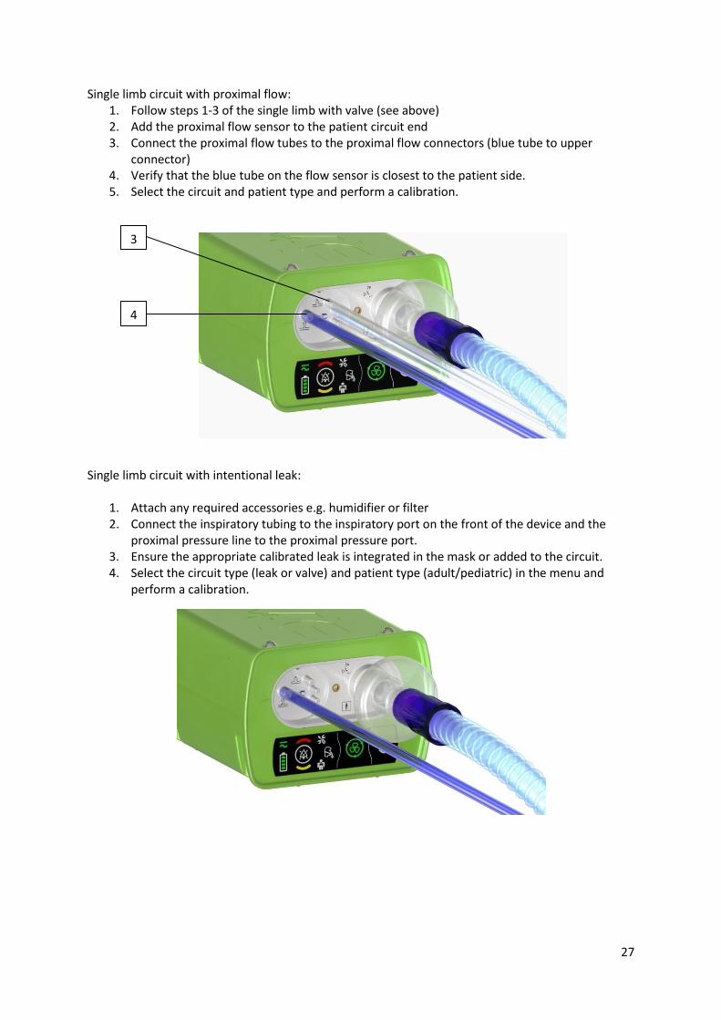
Single limb circuit with proximal flow: 1. Follow steps 1-3 of the single limb with valve (see above) 2. Add the proximal flow sensor to the patient circuit end 3. Connect the proximal flow tubes to the proximal flow connectors (blue tube to upper
connector) 4. Verify that the blue tube on the flow sensor is closest to the patient side. 5. Select the circuit and patient type and perform a calibration.
Single limb circuit with intentional leak:
1. Attach any required accessories e.g. humidifier or filter 2. Connect the inspiratory tubing to the inspiratory port on the front of the device and the
proximal pressure line to the proximal pressure port. 3. Ensure the appropriate calibrated leak is integrated in the mask or added to the circuit. 4. Select the circuit type (leak or valve) and patient type (adult/pediatric) in the menu and
perform a calibration.
3
4

28
Double limb circuit with adapter:
1. Plug the adapter (see image below) into the front of the EO 150 ventilator and screw tightly to ensure the connection.
2. Attach any required accessories (see image below). 3. Connect the inspiratory tubing to the inspiratory port and the exhalation tube to the
exhalation port. 4. Select the circuit type and perform a calibration.
Image: Double Limb Adapter
CAUTION The double limb circuit adaptor is single-patient-use and disposable.
Exhalation Valve Control Line
Proximal Flow Sensor (Blue Line)
LineLineLine
Proximal Flow Sensor (Clear line)
LineLineLine

29
WARNING
Rebreathing may occur when using a single limb circuit with intentional leak if the pressure is too low for a given leak diameter .
Ensure the vent holes at the mask or constant leaks at the vented interface port are not obstructed.
Accessories Compatible with EO-150
The EO-150 ventilator is compatible with a range of accessories.
FIO2 Cable add part numbers
Car Adaptor DC Cable
SPO2 Cable
Transport Bag
Nomad Bag
Travel Bag
Remote Alarm Cable
EO-Remote Vision Tablet
EO-Remote Vision Smartphone App
Breathing circuit, single limb Vented (no valve)
Breathing circuit, single limb with valve
Proximal Flow sensor
WARNING
Before using any accessory, always carefully read the accompanying Quick User Guide and User Manual.
The EO-150 Ventilator should only be used with accessories recommended by EOVE. Connection of other accessories could result in patient injury or damage to the device.
Attaching patient circuit accessories
WARNING
Adding or removing circuit components can adversely affect ventilation performance.
A circuit calibration is recommended every time an accessory or component is added to or

30
removed from the patient circuit.
Do not use electrically conductive or anti-static air tubing.
Attaching an antibacterial filter
WARNING
To prevent the risk of cross-contamination, an antibacterial filter is mandatory if the device is to be used on multiple patients.
Regularly check the antibacterial filter and expiratory valve for signs of moisture or other contaminants, particularly during nebulisation or humidification. Failure to do so could result in increased breathing system resistance and/or inaccuracies in expired gas measurement.
Only use antibacterial filters that comply with the relevant safety standards, including ISO 23328-1 and ISO 23328-2.
CAUTION
The antibacterial filter must be used and replaced according to the manufacturer's specifications.
To attach an antibacterial filter to the EO-150:
1. Attach the antibacterial filter to the inspiratory port of the device. 2. Connect the breathing tube to the other side of the filter. 3. Perform a calibration. 4. Connect the patient interface to the other end of the breathing tube.
Attaching a humidifier
WARNING
Humidification of the inspired gas is required for invasive ventilation in order to prevent any lung injury.
Always place the humidifier on a level surface lower than level of the ventilator and the patient in order to prevent the mask and tubing filling with water.
Ensure that the humidifier is set up according to the manufacturer's instructions.
Use appropriate precautions to prevent water in the circuit transferring to the patient (e.g., a water trap).
Only use HMEs that comply with the relevant safety standards, including ISO 9360-1 and ISO 9360-2.
CAUTION
Make sure that the water tub is empty and thoroughly dried before transporting the humidifier.
To attach a humidifier to a circuit configuration:
1. Connect the air tubing to the inspiratory port on the device. 2. Connect the other end of the air tubing to the inlet port on the humidifier. 3. Connect the patient circuit to the outlet port on the humidifier.
2
2 3

31
Attaching oxygen
WARNING
Use only medical grade oxygen.
Ensure that the device is ventilating before the oxygen supply is turned on.
The oxygen flow must be turned off when the device is not ventilating so that oxygen does not accumulate within the device. The accumulation of oxygen presents a fire risk.
Oxygen supports combustion. Only use oxygen in well-ventilated rooms. Using oxygen while smoking or in the presence of an open flame creates a fire hazard.
Supplemental oxygen must be added into EO 150 Ventilator’s oxygen inlet at the rear of the device.
Monitor supplemental oxygen using the optional FiO2 cell kit and relative alarms.
Do not use oxygen source pressure above 50 KPa. If pressure exceeds this level at the oxygen inlet, the oxygen source tubing may disconnect from the oxygen adaptor. In this case, the oxygen supply must be cut off immediately.
Always turn off the oxygen supply when ventilation is stopped for any reason.
The EO-150 Ventilator is not designed for use with anesthetic gases.
Oxygen can be added up to a maximum flow of 20l/min. However, the ventilator is not adapted to provide Fi02 concentrations above 50%.
For a given O2 flow, O2 concentration may vary with many parameters such as volume, inspiratory time, rate, PEEP, leak, interface, patient circuit.
To add supplemental oxygen:
1. Unlock the oxygen inlet at the rear of the device by pushing up on the locking clip. 2. Plug in the oxygen adaptor (supplied with the EO 150) to the oxygen inlet. 3. Attach the end of the oxygen supply tube (provided with the EO 150) to the oxygen adaptor. 4. Attach the other end of the oxygen supply tube to the oxygen source. 5. Start ventilation. 6. Turn on the oxygen and adjust for the prescribed flow rate or FiO2 level.
To remove supplemental oxygen: 1. Turn off the oxygen source.
1

32
2. Unlock the low flow oxygen inlet at the rear of the device by pushing up on the locking clip. 3. Remove the oxygen adaptor from the oxygen port.
Image: Theoretical variation of the % FIO2 in function of tidal volume in ml
CAUTION Ensure oxygen supply has been turned off before removing supplemental
oxygen.
Attaching an FiO2 sensor
WARNING
The EO-150 Ventilator can be used with an optional Fi02 sensor with minimum and maximum concentration alarms. This sensor should always be used in order to ensure that the prescribed oxygen concentration is delivered to the patient.
1. Plug the FiO2 cable into the FiO2 port.
2. Plug the FiO2 sensor into the other end of the Fi02 cable.
3. Attach the T-adaptor to the Inspiratory Patient Port
4. Plug the Fi02 sensor into the T-adaptor.
NOTE:
In order to display the FiO2 measurements and to set the alarms, activate FiO2 monitoring in the Patient/Circuit configuration menu.
Attaching a pulse oximeter
WARNING
Only use compatible NONIN finger pulse sensors
CAUTION
Some factors may degrade the performance of the pulse oximeter or affect the accuracy of the readings (e.g. blood flow restrictors (arterial catheters, blood pressure cuffs, infusing lines, etc.), excessive ambient light, excessive motion, electromagnetic interference, moisture
0
10
20
30
40
50
60
70
80
90
100
0 200 400 600 800 1000 1200
2 l/min O2
5 l/min O2
10 l/min O2
15 l/min O2

33
in the sensor, improperly applied sensor, incorrect sensor type, a sensor not at heart level, poor pulse quality, venous pulsations, anemia or low haemoglobin concentrations, cardiogreen or other intravascular dyes, carboxyhaemoglobin, methemoglobin, dysfunctional haemoglobin, artificial nails or fingernail polish.
To connect the pulse oximeter:
1. Connect the plug of the pulse oximeter to the SpO2 (pulse oximeter) connector at the rear of the device.
2. Attach to patient.
CAUTION
To remove the cable, pull firmly on the locking ring. Do not twist.
NOTE: In order to display the SP02 measurements and to set the alarms, activate SP02 monitoring in the Patient/Circuit configuration menu.
Attaching a remote alarm
A remote alarm can be connected to the EO-150 ventilator with the Remote Alarm Cable Accessory. This alarm alerts you to an event that requires immediate attention. An audible and visual alarm is triggered when an alarm is activated on the ventilator. For full instructions on using the Remote Alarm, see the Remote Alarm User Guide.
NOTE: In order to display the SP02 measurements and to set the alarms, activate SP02 monitoring in the Patient/Circuit configuration menu.
Power Connections
WARNING
Beware of electrocution. Do not immerse the device, power supply or power cord in water.
Make sure the power cord and plug are not damaged and the equipment is in good condition.
Keep the power cord and device away from hot surfaces.
Explosion hazard—do not use in the vicinity of flammable anesthetics.
The EO 150 ventilator can be used with three different power sources:
Mains power
Internal battery
External DC power supply (e.g., car 12V power outlet). For information on power supplies and sources see the Technical Specifications.
Connecting to mains power
WARNING

34
Ensure that the power cord does not pose a tripping or choking hazard.
Ensure that the home AC mains supply and connections are safe and comply with the applicable regulations. For ventilator dependant patients, consider using a back-up power system.
To connect to mains power:
1. Connect the DC plug of the supplied external power supply unit to the rear of the EO 150 module or docking station. Ensure the connection is correctly aligned. Secure the connection by screwing the connector firmly in place.
2. Plug the other end of the power cord into the power outlet.
NOTE: Do not twist or tug the power cord or the outer housing of the connector.
Running the ventilator on internal battery
WARNING
When using the EO-150 as a backup ventilator, check the internal battery level regularly.
As the battery ages, the available capacity decreases. When the remaining battery capacity is low, do not rely on the internal battery as the primary power supply.
The internal battery should be replaced every two years, or when a service notification is displayed.
Replacement of lithium batteries or fuel cells by anyone other than trained personnel will result in dangerous risk (e.g., excessive temperatures, fire or explosion)
The internal battery and any other device component should be disposed of following appropriate waste management regulations.
CAUTION
Plug device into AC mains power when the remaining capacity of the battery is low.
The internal battery may stop charging when ambient temperatures of 35°C or more are reached.
If AC power is lost, the battery is guaranteed to continue to provide ventilation for at least 1 hour. Find an alternate supply or alternative means of ventilation e.g. back-up ventilator or manual ventilation means.
If the EOVE device is left in storage for an extended period of time the internal battery will become depleted. If storing your device, recharge the internal battery once every six months.
Storing the ventilator at temperatures higher than 50°C for extended periods will accelerate battery ageing. This will not affect the safety of the battery or the device.
The internal battery of the EOVE ventilator allows your ventilator to operate even when mains power is disrupted or when the device is not connected to the mains. When the EOVE ventilator is operating on internal battery power, you are notified of the level of charge in the battery by the battery power source indicators both on the keyboard and touch screen.
NOTE:
The internal battery continues to charge when the device is connected to mains power, even when it is operating or on standby.

35
The internal battery takes 2 hours to fully charge from empty without ventilation and 6 hours when ventilating.
Battery run time
When the internal battery is being used to power the device, the amount of charge remaining in the battery is displayed as shown in the following table.
Touch Screen
Keyboard Display Description
When the internal battery is in use, the battery charge level is displayed by percentage on the touch screen and by 4 LEDs on the keyboard.
When the internal battery is charging, the charge battery symbol is displayed on the touch screen and by scrolling LEDs on the keyboard.
When the internal battery power is low, the charge battery symbol is displayed in red on the touch screen and the LED’s on the keyboard are red.
Alarms will alert the user when the battery power is getting low Internal battery run time is determined by:
Environmental conditions (operating conditions See Technical Specifications)
The condition and age of the battery
The device settings
The current circuit in place and unintentional leak
The internal battery will operate for approximately six hours when the device is used according to the following configuration for an adult patient: Inspiratory pressure: 20mb Ventilation Rate: 15 bpm PEEP: OFF
Storing and recharging
If the device is being stored, its internal battery must be recharged every six months during the storage period.
Prepare the battery for long-term storage:
1. The battery charge level should be between 50 and 100%. If not, charge the device to at least 50% capacity before storing by connecting to mains power.
2. Turn off the device.
3. Remove the power cord from the device.

36
Connecting to an external DC power source
CAUTION
When using a car auxiliary adapter, start the car before plugging in the DC Adapter of the device.
If the external DC power source drops to below 12V, the EO 150 Ventilator will switch to internal battery.
To connect to DC power: 1. Connect the DC power cord into the rear of the device. 2. Plug the other end of the power cord into the power outlet.
Travelling with the EOVE Ventilator, the Click-and-Go system .
Several solutions are available which allow you freedom and mobility with the EO 150 Ventilator, whether for a short time or for travelling longer distances. See the table below for the recommended use of each EOVE Bag.
WARNING
The EO-Series Ventilator should not be operated while in the Transport bag. To ventilate while travelling, use the EO-Series Ventilator accessory bags: Nomad bag or Travel bag.
CAUTION
Do not place any heavy or bulky objects in the zippered pocket on the inside front of the bag. This could result in damage to the touch screen.
Type of Bag Recommended Use
Transport Use for storing the EOVE device with its docking station. Use whenever the device is not in use to prevent damage. Use to store cables and patient circuits.
Travel Use for travelling and using the device while it is in its docking station. Use to store cables and patient circuits.
Nomad Use for travelling and using the device without its docking station.
37
Using the Nomad Bag (no docking station)
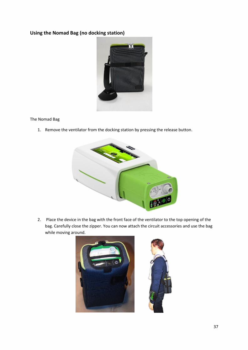
The Nomad Bag
1. Remove the ventilator from the docking station by pressing the release button.
2. Place the device in the bag with the front face of the ventilator to the top opening of the
bag. Carefully close the zipper. You can now attach the circuit accessories and use the bag
while moving around.

38
NOTE: For best autonomy use nomad with the touch screen separated. (remote vision)
Using the Transport bag
WARNING
The Transport bag is only to be used to transport the ventilator. Ventilation cannot take place when the ventilator is in this bag.
Before placing the EOVE device in the bag: 1. Remove the device from the outer housing. 2. Remove the power cord from the rear of the device 3. Remove all patient circuit components 4. Remove all accessories 5. Place the device carefully into the bag, ensuring that the touch screen is facing upwards. 6. Ensure all zippers are completely closed and the device is secure before lifting the bag.
Chapter 4: Alarms
WARNING
Test the effectiveness of the alarm after any changes to the circuit, ventilation settings or co-therapy. Alarm settings are sensitive to these changes.
Alarms may deactivate if the alarms are set to extreme values. This could put the patient at risk.
The EOVE 150 is equipped with alarms to ensure the safety of the patient and to alert the user to certain conditions that require a response. When an alarm is activated, it is both audible and visible.
When an alarm is activated:
1. A series of beeps will sound 2. A message will appear on the touch screen showing the priority of the alarm and giving the
reason for the alarm 3. A pop-up on the Home Screen will show the nature and priority of the alarm and the red
arrow on the touch screen will flash until it is selected 4. The alarm button on the top panel of the machine will also flash and the icons will indicate
the nature of the alarm.

39
Viewing active alarms
1. Press to access the alarms Log screen from the Home Screen.
2. Hold to temporarily mute the alarm. The alarm sound will be temporarily muted for two
minutes. If after two minutes the conditions of the alarm are still present, the alarm sound will
be set off again.
3. The Alarm Events screen gives information about the alarms in chronological order. 4. When there is an active alarm, the alarm indicators flash red on the top bar of the screen. 5. Touch the screen or swipe upwards to get back to the Home Screen.

40
NOTE: The red arrow in the touch screen display is visible from all screens and indicates that there are one or more active alarms.
Alarm priority
Alarms are classified into relative priority (High and Medium) according to the severity and urgency of the alarm condition. The alarm will appear on both the keyboard and the touch screen. See details below in the table.
Alarm priority Keyboard Touch Screen Audible alert
High Red flashing light Red Alarm Type symbol 10 beeps every 6 seconds
Medium Yellow flashing light Yellow Alarm Type symbol 2 beeps every 15 seconds
NOTE: All alarms should be responded to, but an immediate response is required for high priority alarms.
Troubleshooting Alarms
Note: Check the patient’s status before responding to an alarm. Switch to back-up ventilator if necessary.
If extreme alarm settings are set, alarms may not trigger.
Alarm Cause/Ventilator response
Action needed Type of Alarm
Total Power Loss Continuous sound: Alarm activates immediately
Check power connections. If the power loss alarm continues, contact your service provider and use a back up ventilator.
Disconnection High Priority
A tube or accessory has become disconnected. Alarm activates after 1 cycle. Check all tube and accessory connections.
Prox. Fail High Priority
Proximal sensor fail. Alarm activates after 1 second. Contact your service provider
Prox. Disconnection High Priority
Proximal sensor disconnected. Alarm activates after 1 second. Reconnect proximal sensor
Valve Disconnected High Priority
Valve disconnected. Alarm activates after 1 cycle. Reconnect valve
Occlusion High Priority
Patient circuit is blocked. Alarm activates after 6 cycles. Check that the patient mask or tubing are not obstructed.
Remove Valve High Priority
The ventilation settings are not compatible with the type of patient circuit used. Alarm activates after 1 cycle.
Check the settings and the patient circuit
Valve Leak High Priority
There is a leak in the circuit configuration. Alarm activates after 6 cycles.
Inspect the circuit, expiratory valve and proximal lines for leak. Check for leaks around the mask if one is being used.
Ventilation stop High Priority
Ventilation stopped voluntarily by clinician or patient. Alarm activates after 1 second. Confirm that the ventilation stop is appropriate or necessary.
Rebreathing High Priority
Not enough leak in LEAK mode or valve not correctly functioning in VALVE mode. Alarm activates after 6 cycles.
Check calibrated leak is the right size or of expiratory pressure is high enough. (LEAK mode) Check valve function. (VALVE mode)
PEEP out of range High Priority
PEEP not correctly regulated. Alarm activates after 6 cycles.
Check the circuit and expiratory valve for occlusion. Check for occlusion in proximal lines, if in use.
Abs. Pres. Fail High Priority
Alarm activates after 1 second.

41
Expi. Flow Fail High Priority
Alarm activates after 1 second Contact your service provider End of Battery High Priority
The battery is depleted. Alarm activates after 1 second. Guaranteed ventilation time after alarm is triggered : 10 min.
Reconnect to mains power
Speed Fault High Priority
Turbine speed too low and temperature too high. Alarm activates after 1 cycle. Contact your service provider
Check Settings High Priority
Settings are not within the parameters. Alarm activates after 1 second. Check the settings are within the parameters. Call your service provider
Memory Fail High Priority
Failure to save parameters set. Alarm activates after 1 second. Contact your service provider
Vol. out of range High Priority
Maximum volume reached. Alarm activates after 6 cycles. Contact your service provider
Turbine Fail High Priority
The turbine is not functioning properly. Alarm activates after 1 cycle. Contact your service provider
Turbine overheat High Priority
Alarm activates after 1 cycle Contact your service provider INSP Flow Fail High Priority
Inspiratory flow sensor fail. Alarm activates after 1 cycle. Contact your service provider
Sec. Pres. Fail High Priority
Security pressure sensor fail. Alarm activates after 1 second. Contact your service provider
Remote Fail Medium Priority
Remote Alarm control fail. Alarm activates after 1 cycle Contact your service provider
Low FiO2 Medium priority
The level of oxygen delivered by the ventilator is below the Min FIO2 level set. Alarm activates after 6 cycles.
Check for leak. Check and adjust the oxygen supply settings and the connections.
High FIO2 Medium Priority
The level of oxygen delivered by the ventilator exceeds the Max FIO2 level set. Alarm activates after 6 cycles.
Check and adjust the oxygen supply and settings.
High Leak Medium Priority
The leak estimated by the ventilator exceeds the maximum Leak threshold. Alarm activates after 6 cycles.
Inspect the circuit, expiratory valve and proximal lines for leak. Check for leaks around the mask, if in use.
High Pres Medium Priority
Inspiratory pressure is too high. Alarm activates after 3 cycles. Inspect the circuit for occlusion.
High VTI Medium Priority
Inspired tidal volume is too high. Alarm activates after 6 cycles.
Inspect the circuit and expiratory module for leaks.
Low VTI Medium Priority
Inspired tidal volume is too low. Alarm activates after 6 cycles. Inspect the circuit and expiratory module and check the pressure settings.
Low VTE Medium Priority
Expired tidal volume is too low. Alarm activates after 6 cycles. Inspect the expiratory valve and check the settings.
High VTE Medium Priority
Expired tidal volume is too high. Alarm activates after 6 cycles. Inspect the expiratory valve and replace, if necessary.
Low MV Medium Priority
Low tidal volume. Alarm activates after 6 cycles. Check for leaks or loose connections.
High Resp. Rate Medium Priority
Patient respiratory rate is too high. Alarm activates after 6 cycles. Check the patient and the ventilator settings.
Low SPO2 Medium Priority
The Pulse Oximeter is recording low SPO2 levels. Alarm activates after 6 cycles. Check the patient and check that the pulse oximeter is correctly attached.
AC Power Loss Medium Priority
Connection to AC power has been lost. Alarm activates after 1 second. Check the power cord is correctly plugged in to mains power and to the ventilator.
DC Power Loss Medium Priority
Connection to DC power has been lost. Alarm activates after 2 seconds. Check the power cord is correctly plugged into the DC source and into the ventilator.
Low Batt. Medium Priority
Battery power is low. Alarm activates after 1 second. Guaranteed ventilation time left: 30 mins.
Plug the ventilator in to either AC or DC power source.
Batt. Temp. High Medium Priority
Battery has high internal temperature. Alarm activates after 10 minutes. Check the level of the battery charge.
Supply Fail Medium Priority
Power supply not detected. Alarm activates after 1 second. Contact your service provider.
Battery Fail Medium Priority
Battery is not functioning correctly. Alarm activates after 10 seconds. Contact your service provider.
Buzzer Fail Medium Priority
One of the buzzers is not functioning properly. Backup buzzer activated. Alarm activates after 1 buzzer cycle
Contact your service provider
Buzzer Batt. Low Medium Priority
The buzzer battery is too low to sound the SUPPLY FAIL alarm. Alarm activates
after 1 second Contact your service provider
CPU Fail Medium Priority
Internal failure Contact your service provider
Valve Fail Low
Exhalation control valve failure. Alarm activates after 1 cycle. Contact your service provider Keyboard Fail Medium Priority
Keyboard stopped working. Alarm activates after 20 seconds. Contact your service provider
Batt. Charge Fail Medium Priority
Internal charger failure Check the level of the battery charge. If problem persists, Contact your service provider.

42
Data management
The EO -150 ventilator provides easy-to-use options for data management with the following options for saving and monitoring data and connecting to remote monitoring systems.
These solutions include:
Wifi
Bluetooth
RF port
Remote Vision App for Smart phone and tablet
The EO-150 stores data monitoring every minute. Data is stocked in the module. The software created by EOVE can be used to analyse this data. Pressure and flow data is stored at the rate of 20 hz.
WARNING
Only connect devices specially designed and recommended by EOVE to the data communication ports. Connecting other devices could result in patient injury, or damage to the EO-Series Ventilator device.
Chapter 5: Routine Cleaning and Maintenance
WARNING
Ventilation dependent patients are vulnerable to infections. All equipment should be regularly cleaned and disinfected.
Keep the device, and accessories away from water. Always turn off and unplug the device before cleaning and verify that it is dry before plugging it back in.
CAUTION
Clean only exterior surfaces of the EO150 Ventilator device.
If necessary, wipe the exterior of the device with a damp cloth using a mild cleaning solution.
For all circuit components and hoses, follow the manufacturer's recommendations for cleaning and maintenance.
Warning
Proper cleaning and maintenance of your EOVE device is essential. Cleaning described in this section should be carried out regularly. Refer to the user guides of any accessories in use for detailed instructions specific to those devices.
Maintenance Method Frequency Inspect the condition of the connections and circuit adapters for any moisture or contaminants
Replace and clean as necessary using appropriate cleaning solutions
Weekly

43
Test the alarm sounds See Set Up Test, Chapter 1 Weekly
Check the condition of the air filter
Check for dirt or dust particles. Monthly
Check the charge level of the internal battery
1.Unplug the device from external power and operate the device on internal battery for a minimum of 10 minutes. 2.Reviewing the remaining battery capacity. 3.Restoring external power once the test is complete.
Monthly
Replace the air filter (See image below)
1.Unlock the air filter cover (No.3) at the rear of the ventilation module (No. 1) by turning in an anti-clockwise direction. 2.Pull the air filter cover from the device. 3.Remove the air filter (no.2) from the cover and discard. 4.Insert a new filter into the cover. 5.Insert the air filter and cover back into the device using the four tabs. 6.Turn in a clockwise direction to secure in place.
Every six months (with normal daily use) Change more frequently in a dusty environment.
CAUTION
The air filter cannot be washed or reused.
Ventilator Module
Air filter
Air filter cover

44
Servicing
WARNING
Maintenance of the ventilator should be carried out by a trained technician. Attempting to repair the machine yourself could result in patient injury or damage to the machine.
NOTE: Retain the original packaging to use when shipping to/from service agent.
Maintenance Timetable
The EO-150 should be regularly serviced by an authorized EOVE technician according to the following schedule. The ventilator will provide safe and reliable ventilation for 10 years provided that it is operated and maintained in accordance with the instructions given in this manual. As with all electrical devices, if any problem arises with your EO 150 device, you should exercise caution and have it inspected by an authorized EOVE technician.
Servicing schedule from the date of first use:
Recommended Service Conducted by Instructions
Every 6 months Person trained in the use of EO-150
Check the air filter and replace if necessary (replace earlier if dirty or dusty). Check Double limb circuit adapter membrane, if
used.Replace if necessary.
Every 2 years Qualified EOVE technician Replace internal battery or if service notification is displayed.
Every 20,000/30,000 hours of use
Qualified EOVE technician Replace turbine (depending on the settings chosen and the patient profile (adult or pediatric)
45
Chapter 6: Device information
Technical specifications
WARNING
Due to their resistance to flow, accessories such as filters, water traps and humidifiers many decrease patient pressure during inspiration and increase patient pressure during exhalation.
Physical Specifications:
Docking Specifications: Weight: 1.6 kg Size: 25x21x13 cm
Ventilation Module Specifications Weight: 1.8 kg Size: 24.5x14.5x10 cm
Ventilation Specifications:
The EO-150 can be used in the following ventilation modes:
(A)VCV : Volume Assisted Controlled (with expiration valve)
(A)PCV : Pressure assisted/Controlled (with expiration valve)
PSV : Pressure support Ventilation (with expiration valve)
MPV : Mouth Piece Ventilation
PSV VT : Pressure support ventilation Volume regulated (with expiratory valve)
V-SIMV : Volume Synchroneous intermittent Mandatory Ventilation (with expiratory Valve)
P-SIMV : Pressure Synchroneous intermittent Mandatory Ventilation (with expiratory valve)
CPAP : Continuous Positive Airway Pressure (with leak)
ST : Synchronised Timed (with leak)
PAC : Pressure Assisted/ Controlled (with leak)
VTS : Volume Target Synchronised (with leak)
46
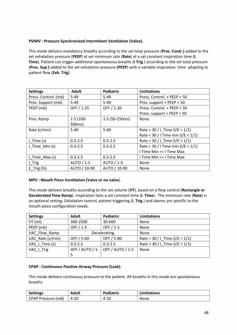
(A)VCV mode Volume Assisted Controlled ventilation (Valve).
This mode delivers breaths according to the set volume (VT), based on a flow control (Rectangle or Decelerated Flow Ramp). Inspiration lasts a set constant time (I. Time). Exhalation controls the set exhalation pressure (PEEP). Breaths are guaranteed at a set minimum rate (Rate).Patient can increase rate by inspiration triggering (I. Trig.).
Setting Adult Pediatric Limitations
VT (ml) 300-2500 30-600 None
PEEP (mb) OFF / 1-25 OFF / 1-20 None
Flow Ramp 1 (Rectangle), 2 (Decelerating) None
Rate (c/min) 5-60 5-80 Rate < 30 / I_Time (I/E < 1/1)
I Time (s) 0.3-2.5 0.3-2.5 Rate < 30 / I_Time (I/E < 1/1)
I Trig. OFF / AUTO / 1-5 OFF / AUTO / 1-5 None
(A)PCV Mode P(A)CV : Pressure Assisted Controlled Ventilation (Valve). This mode delivers breaths according to the set total pressure,(Pres. Sup.) added to the set exhalation pressure (PEEP). Inspiration lasts a set constant time (I. Time). Breaths are guaranteed at a set minimum rate (Rate). Patient can increase rate by inspiration triggering (I. Trig.).
Setting Adult Pediatric Limitations
Press. Control. (mb) 5-49 5-49 Press. Control. + PEEP < 50 mb
PEEP (mb) OFF / 1-25 OFF / 1-20 Press. Control. + PEEP < 50 mb
Press_Ramp (ms) 1-5 (100-500ms) 1-5 (50-250ms) None
Rate (c/min) 5-60 5-80 Rate < 30 / I_Time (I/E < 1/1)
I Time (s) 0.3-2.5 0.3-2.5 Rate < 30 / I_Time (I/E < 1/1)
I Trig OFF / AUTO / 1-5 OFF / AUTO / 1-5 None
PSV Mode PSV : Pressure Support Ventilation (Valve).
This mode delivers breaths according to the set total pressure, (Pres. Sup.) added to the set exhalation pressure (PEEP). Inspiration time is variable adapting to patient flow (Exh. Trig). Breaths are guaranteed at a set minimum rate (Rate).Patient can increase rate by inspiration triggering (I. Trig.).
Settings Adult Pediatric Limitations
Pres. Support (mb) 5-49 5-49 Pres. support + PEEP < 50
PEEP (mb) OFF / 1-25 OFF / 1-20 Pres. support + PEEP < 50
Pres. Ramp 1-5(100ms-500ms) 1-5 (50-250ms) None
Rate (c/min) 5-60 5-80 Rate < 30 / I Time min (I/E < 1/1) Apnea > 60/Rate
Apnea AUTO / 2-30 AUTO / 1-15 Apnea > 60/Rate
I Time Min (s) AUTO / 0.3-2.5 AUTO / 0.3-2.5 Rate < 30 / I Time min (I/E < 1/1) I Time Min <= I Time Max
I Time Max (s) AUTO / 0.3-2.5 AUTO / 0.3-2.5 I Time Min <= I Time Max
I Trig AUTO / 1-5 AUTO / 1-5 None
Exh. Trig (%) AUTO / 10-90 AUTO / 10-90 None

47
PSV VT : Pressure Support Ventilation with VT Target (Valve).
This mode delivers breaths according to the set target volume (VT), based on pressure control adapting breath by breath, between the set total pressure limits (P. Sup. Min. and P Sup Max) added to the set exhalation pressure (PEEP). Inspiration time is variable according to patient flow (Exh. Trig). Breaths are guaranteed at a set minimum rate (Rate). Patient can increase rate by inspiration triggering (I. Trig.).
Settings Adult Pediatric Limitations
VT (ml) 300-2500 30-600 None
Pres sup Min (mb) 5-48 5-48 Pres sup Min < Pres sup Max
Pres sup Max (mb) 10-49 10-49 Pres sup Min < Pres sup Max + 5 Pres sup Max + PEEP < 50
PEEP (mb) OFF / 1-25 OFF / 1-20 None
Press Ramp 1-5 (100-500ms) 1-5 (50-250ms) None
Rate (c/min) 5-60 5-80 Rate < 30 / I Time min (I/E < 1/1) Apnea > 60/Rate
Apnea AUTO / 2-30 AUTO / 1-15 Apnea > 60/Rate
I Time Min (s) AUTO / 0.3-2.5 AUTO / 0.3-2.5 Rate < 30 / I Time min (I/E < 1/1) I Time Min <= I Time Max
I Time Max (s) AUTO / 0.3-2.5 AUTO / 0.3-2.5 I Time Min <= I Time Max
I Trig AUTO / 1-5 AUTO / 1-5 None
Exh.Trig (%) AUTO / 10-90 AUTO / 10-90 None
VSIMV : Volume Synchronized Intermitent Ventilation (Valve).
This mode delivers mandatory breaths according to the set volume (VT), at set minimum rate (Rate) and a set constant inspiration time (I. Time). Patient can trigger additional spontaneous breaths (I Trig.) according to the set total pressure (Pres. Sup.) added to the set exhalation pressure (PEEP) with a variable inspiration time adapting to patient flow (Exh. Trig).
Settings Adult Pediatric Limitations
VT (ml) 300-2500 30-600 None
Pres. Support (mb) 5-49 5-49 Pres. Support + PEEP < 50
PEEP (mb) OFF / 1-25 OFF / 1-20 Pres. Support + PEEP < 50
Press Ramp 1-5 (100-500ms) 1-5 (50-250ms) None
Rate (c/min) 5-40 5-60 Rate < 30 / I_Time (I/E < 1/1) Rate < 30 / I Time min (I/E < 1/1)
I Time (s) 0.3-2.5 0.3-2.5 Rate < 30 / I_Time (I/E < 1/1)
I Time Min (s) 0.3-2.5 0.3-2.5 I Time Min <= I Time Max Rate < 30 / I Time min (I/E < 1/1)
I Time Max (s) 0.3-2.5 0.3-2.5 I Time Min <= I Time Max
I Trig AUTO / 1-5 AUTO / 1-5 None
Exh.Trig (%) AUTO / 10-90 AUTO / 10-90 None
48
PSIMV : Pressure Synchronized Intermitent Ventilation (Valve).
This mode delivers mandatory breaths according to the set total pressure (Pres. Contr.) added to the set exhalation pressure (PEEP) at set minimum rate (Rate) at a set constant inspiration time (I. Time). Patient can trigger additional spontaneous breaths (I Trig.) according to the set total pressure (Pres. Sup.) added to the set exhalation pressure (PEEP) with a variable inspiration time adapting to patient flow (Exh. Trig).
Settings Adult Pediatric Limitations
Press. Control. (mb) 5-49 5-49 Press. Control. + PEEP < 50
Pres. Support (mb) 5-49 5-49 Pres. support + PEEP < 50
PEEP (mb) OFF / 1-25 OFF / 1-20 Press. Control. + PEEP < 50 Press. support + PEEP < 50
Pres. Ramp 1-5 (100-500ms)
1-5 (50-250ms) None
Rate (c/min) 5-40 5-60 Rate < 30 / I_Time (I/E < 1/1) Rate < 30 / I Time min (I/E < 1/1)
I_Time (s) 0.3-2.5 0.3-2.5 Rate < 30 / I_Time (I/E < 1/1)
I_Time_Min (s) 0.3-2.5 0.3-2.5 Rate < 30 / I Time min (I/E < 1/1) I Time Min <= I Time Max
I_Time_Max (s) 0.3-2.5 0.3-2.5 I Time Min <= I Time Max
I_Trig AUTO / 1-5 AUTO / 1-5 None
E_Trig (%) AUTO / 10-90 AUTO / 10-90 None
MPV : Mouth Piece Ventilation (Valve or no valve).
This mode delivers breaths according to the set volume (VT), based on a flow control (Rectangle or Decelerated Flow Ramp). Inspiration lasts a set constant time (I. Time). The minimum rate (Rate) is an optional setting. Exhalation control, patient triggering (I. Trig.) and alarms are specific to the mouth piece configuration needs. :
Settings Adult Pediatric Limitations
VT (ml) 300-2500 30-600 None
PEEP (mb) OFF / 1-5 OFF / 1-5 None
VAC_Flow_Ramp Decelerating None
VAC_Rate (c/min) OFF / 5-60 OFF / 5-80 Rate < 30 / I_Time (I/E < 1/1)
VAC_I_Time (s) 0.3-2.5 0.3-2.5 Rate < 30 / I_Time (I/E < 1/1)
VAC_I_Trig OFF / AUTO / 1-5
OFF / AUTO / 1-5 None
CPAP : Continuous Positive Airway Pressure (Leak).
This mode delivers continuous pressure to the patient. All breaths in this mode are spontaneous breaths.
Settings Adult Pediatric Limitations
CPAP Pressure (mb) 4-20 4-20 None

49
ST : Synchronized Timed mode (Leak).
This mode delivers breaths according to the set inspiration pressure (IPAP) and set exhalation pressure (EPAP). Inspiration time is variable adapting to patient flow (Exh. Trig). Breaths are guaranteed at a set minimum rate (Rate). Patient can increase rate by inspiration triggering (I. Trig.).
Settings Adult Pediatric Limitations
IPAP (mb) 6-50 6-50 IPAP > EPAP + 2
EPAP (mb) 4-25 4-20 IPAP > EPAP + 2
Press Ramp 1-5 (100-500ms) 1-5 (50-250ms) None
Rate (c/min) 5-60 5-80 Rate < 30 / I Time min (I/E < 1/1) I Time Min <= I Time Max
I Time Min (s) 0.3-2.5 0.3-2.5 Rate < 30 / I Time min (I/E < 1/1) I Time Min <= I Time Max
Apnea AUTO / 2-30 AUTO / 1-15 Apnea > 60/Rate
I Time Max (s) 0.3-2.5 0.3-2.5 I Time Min <= I Time Max
I Trig AUTO / 1-5 AUTO / 1-5 None
E Trig (%) AUTO / 10-90 AUTO / 10-90 None
PAC: Pressure Assisted Controlled mode (Leak).
This mode delivers breaths according to the set inspiration pressure (IPAP) and set exhalation pressure (EPAP). Inspiration lasts a set constant time (I. Time). Breaths are guaranteed at a set minimum rate (Rate). Patient can increase rate by inspiration triggering (I. Trig.).
Settings Adult Pediatric Limitations
IPAP (mb) 6-50 6-50 IPAP > EPAP + 2
EPAP (mb) 4-25 4-20 IPAP > EPAP + 2
Pres. Ramp (ms) 1-5 (100-500ms) 1-5(50-250ms) None
Rate (c/min) 5-60 5-80 Rate < 30 / I_Time (I/E < 1/1)
I Time (s) 0.3-2.5 0.3-2.5 Rate < 30 / I_Time (I/E < 1/1)
I Trig OFF / AUTO / 1-5 OFF / AUTO / 1-5 None
VTS : Volume Target Synchronized mode (Leak).
This mode delivers breaths according to the set volume (VT) based on pressure control adapting breath by breath, between the set pressure limits (IPAP Min. and IPAP Max). Inspiration time is variable adapting to patient flow (Exh. Trig). Breaths are guaranteed at a set minimum rate (Rate). Patient can increase rate by inspiration triggering (I. Trig.).
Settings Adult Pediatric Limitations
VT (ml) 300-2500 30-600 None
IPAP Min (mb) 4-49 4-49 IPAP Max > IPAP Min + 5
IPAP Min > EPAP + 2
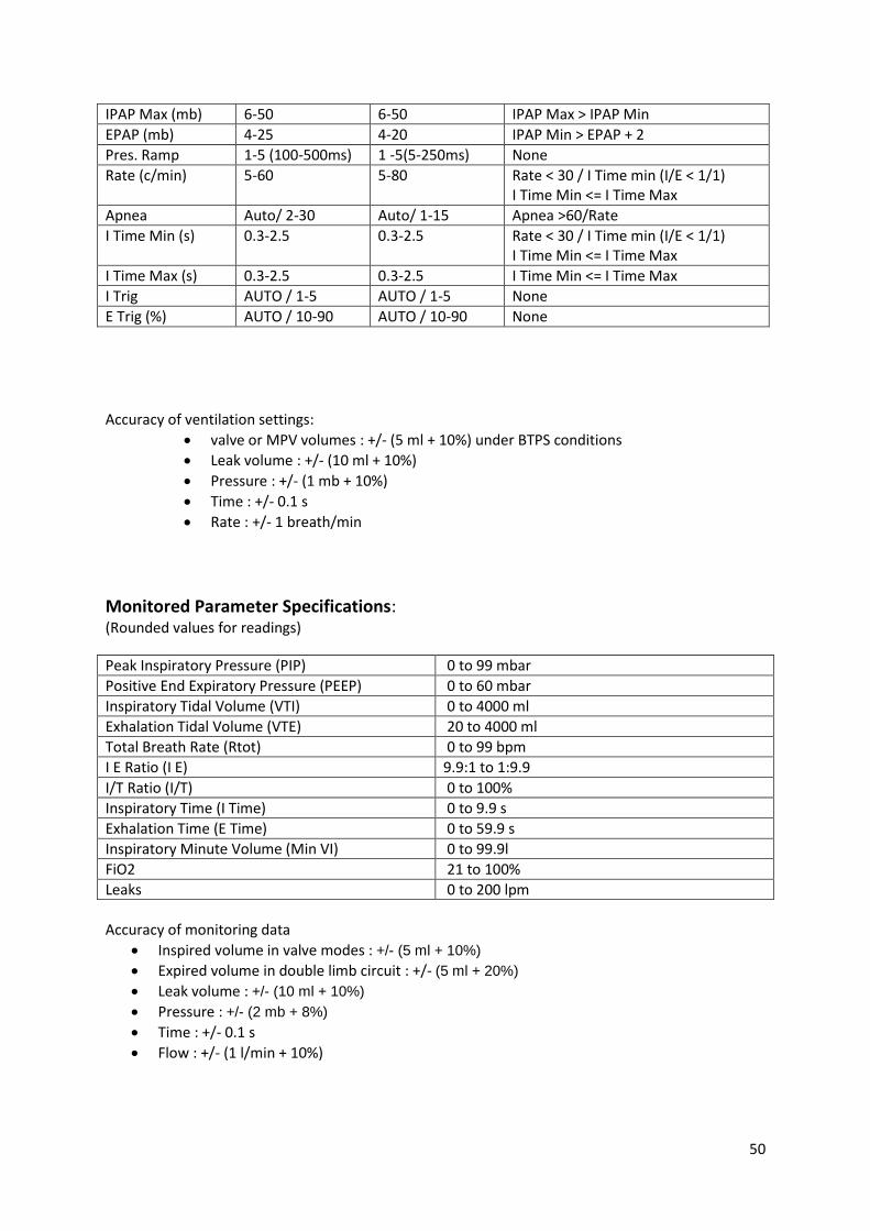
50
IPAP Max (mb) 6-50 6-50 IPAP Max > IPAP Min
EPAP (mb) 4-25 4-20 IPAP Min > EPAP + 2
Pres. Ramp 1-5 (100-500ms) 1 -5(5-250ms) None
Rate (c/min) 5-60 5-80 Rate < 30 / I Time min (I/E < 1/1) I Time Min <= I Time Max
Apnea Auto/ 2-30 Auto/ 1-15 Apnea >60/Rate
I Time Min (s) 0.3-2.5 0.3-2.5 Rate < 30 / I Time min (I/E < 1/1) I Time Min <= I Time Max
I Time Max (s) 0.3-2.5 0.3-2.5 I Time Min <= I Time Max
I Trig AUTO / 1-5 AUTO / 1-5 None
E Trig (%) AUTO / 10-90 AUTO / 10-90 None
Accuracy of ventilation settings:
valve or MPV volumes : +/- (5 ml + 10%) under BTPS conditions
Leak volume : +/- (10 ml + 10%)
Pressure : +/- (1 mb + 10%)
Time : +/- 0.1 s
Rate : +/- 1 breath/min
Monitored Parameter Specifications: (Rounded values for readings)
Peak Inspiratory Pressure (PIP) 0 to 99 mbar
Positive End Expiratory Pressure (PEEP) 0 to 60 mbar
Inspiratory Tidal Volume (VTI) 0 to 4000 ml
Exhalation Tidal Volume (VTE) 20 to 4000 ml
Total Breath Rate (Rtot) 0 to 99 bpm
I E Ratio (I E) 9.9:1 to 1:9.9
I/T Ratio (I/T) 0 to 100%
Inspiratory Time (I Time) 0 to 9.9 s
Exhalation Time (E Time) 0 to 59.9 s
Inspiratory Minute Volume (Min VI) 0 to 99.9l
FiO2 21 to 100%
Leaks 0 to 200 lpm
Accuracy of monitoring data
Inspired volume in valve modes : +/- (5 ml + 10%)
Expired volume in double limb circuit : +/- (5 ml + 20%)
Leak volume : +/- (10 ml + 10%)
Pressure : +/- (2 mb + 8%)
Time : +/- 0.1 s
Flow : +/- (1 l/min + 10%)

51
Alarm Parameter Specifications:
Alarm sound level: 75 dB
The ventilator has the following alarm settings in specific ventilation modes:
Settings Adult Pediatric Modes
Pmin (mb) * 2-55 2-55 (A)VCV, MPV, VSIMV
Pmax (mb) * 10-60 10-60 (A)VCV, MPV, VSIMV
Vti Min (ml) 50-2500 30-600 All except (A)VCV, MPV
Vti Max (ml) 60-3000 40-800 (A)PCV, PSV, PSV VT, VSIMV, PSIMV
Vte Min (ml) 50-2500 30-600 All valve modes
Vte Max (ml) 60-3000 40-800 All valve modes
MV Min 1-25 0.5-6 All except (A)VCV
Rate Max 10-70 20-90 (A)VCV, MPV, VSIMV
FIO2 Min 18-80 18-80 (A)VCV, MPV, VSIMV
FIO2 Max 30-100 30-100 All except (A)VCV, MPV
SPO2 Min 80-95 80-95 (A)PCV, PSV, PSV VT, VSIMV, PSIMV
Pmin Timer 5-900 5-900 VAC, VTS
*PWMax and PWmin according to ISO 10651-2
Power specifications :
WARNING
This device is intended to function with external power supply PMP105F-15 from Protek, never use any other power supply unless recommended by Eove
To disconnect the device from the mains, unplug power supply.
AC Inlet Voltage 100-230V
AC Inlet Power 1.4-0.7A
AC Inlet Power 47-63 Hz
DC inlet voltage 12 to 30v
Power 115w maximum
Module Embedded battery life 6hrs Internal battery capacity 2,8 Ah
Interface/touchscreen start up time 1 minute
Ventilator unit start up time 5 seconds
Ventilation guaranteed by battery if AC power loss 1h

52
Environmental Specifications: Storage and transport conditions:
Ambient temperature From -20°C à +60°C.
Relative humidity From 10% à 95%, (non-condensing)
Operating conditions:
Ambient temperature From +5°C to +40°C (after conditioning at 23° for 20 minutes)
Relative humidity From 10% à 95%, (non-condensing).
Atmospheric pressure From 600 hPa à 1100 hPa.
Breathing system Specifications
Inspiratory resistance at 60 l/min Ventilation stopped / Failure
< 3 mb
Expiratory resistance at 60 l/min Ventilation stopped / Failure
< 3 mb
Software versions:
Main: C150 000002 Power: P150 000002 Interface: V2.2.10_API02_TR02
Guidance and Manufacturer’s Declaration Electromagnetic Emissions & Immunity
WARNING
The ventilator should not be used in close proximity to other equipment or stacked on top of other devices. If this kind of use is unavoidable, the ventilator should be checked carefully and observed to ensure correct functioning of the device.
Only accessories recommended for the EO 150 should be used. Using any other accessories could result in risk to the device or the patient.
Any additional equipment connected to medical electrical devices must comply with the respective IEC or ISO standards (eg, IEC 60950 for data processing equipment). Furthermore all configurations shall comply with the requirements for medical

53
electrical systems (see IEC 60601-1-1 or clause 16 of the 3Ed. of IEC 60601-1,respectively). Adding additional equipment configures a medical system and this system must comply with the requirements for medical electrical systems. Any person undertaking this kind of addition shall be responsible to ensure that all requirements are complied with. It is important to note that local laws take priority over the above mentioned requirements. If in doubt, consult an EOVE representative or the technical service department.
Interference may occur in the vicinity of equipment marked with the following symbol:
EO150 is designed for use in the electromagnetic environment described below. Those using the device should ensure that the EO 150 is used in such an environment.
Emissions test Level of compliance
RF emissions CISPR 11 Class B
Harmonic Emissions IEC 61000-3-2
Class A
Voltage Fluctuations/Flicker Emissions IEC 61000-3-3
Complying
Immunity Test Level of compliance
Electrostatic discharge (ESD) IEC 61000-4-2
6 kV contact 8 kV air
Electrical fast transient/burst IEC 61000-4-4
1 kV
Surge IEC 61000-4-5
1 kV differential mode 2 kV common mode
Voltage dips, short interruptions and voltage variations on power supply input lines IEC 61000-4-11
<5% Ut for 0.5 cycle 40% Ut for 5 cycles 70% Ut for 25 cycles <5% Ut for 5 sec
Power frequency (50/60 Hz) magnetic field IEC 61000-4-8
3 A/m
Conducted RF IEC 61000-4-6
3 Vrms 150 kHz to 80 MHz
Radiated RF* IEC 61000-4-3
10 V/m 80 MHz to 2.5 GHz
*Recommended separation distance
d = 1.17 √P
d = 0.35 √P 80 MHz to 800 MHz
d = 0.70 √P 800 MHz to 2.5 GHz Where (P) is the maximum output power rating of the transmitter in watts (W) according to the transmitter manufacturer and d is the recommended separation distance in meters (m). Field

54
strengths from fixed RF transmitters, as determined by an electromagnetic site survey, should be less than the compliance level in each frequency range. Recommended distance between device and portable and mobile RF equipment.
Power (W) 150 kHz to 80 MHz 80 MHz to 800 MHz 800MHz to 2.5 GHz
0.01 0.12 0.04 0.07
0.1 0.37 0.11 0.22
1 1.17 0.35 0.7
10 3.7 1.11 2.21
100 11.7 3.5 7.0
.
Standards compliance: The EO-150 meets the following standards: EN ISO 14971 2012 : Medical Device Risk Management IEC 60601-1 : 2012 amended (Ed 3.1): Medical Electrical Equipment –Part 1: General Requirements for Safety 1: Collateral Standard: Safety Requirements for Medical Electrical Systems The ventilator is classified according to Chapter 5 of the norm CEI 60601-1, as follows :
Class II Equipment Internally Powered Equipment Type BF Applied Parts IP22 with respect to access to hazardous parts and ingress of moisture Not suitable for use in the presence of flammable anesthetic mixtures Not suitable for sterilisation Suitable for continuous operation Detachable power supply cable
IEC 60601-1-2 - 2007 : Medical electrical equipment – Part 1-2: General requirements for basic safety
and essential performance – Collateral Standard: Electromagnetic disturbances – Requirements and
tests
IEC 60601-1-6 December 2006 : Medical Electrical Equipment – Part 1-6 General requirements for basic safety and essential performance – Collateral Standard – Usability IEC 60601-1-8:2003 - Medical Electrical Equipment -Part 1-8 : General requirements for basic safety and essential performance : Tests and guidance for alarm systems in medical electrical equipment and medical electrical systems. EN ISO 10651-2, 2009: Lung ventilators for medical use -- Particular requirements for basic safety
and essential performance -- Part 2: Home care ventilators for ventilator-dependent patients
CEI 60601-1-11:2011: General requirements for basic safety and essential performance -- Collateral standard: Requirements for medical electrical equipment and medical electrical systems used in the home healthcare environment. The EO-150 ventilator conforms to the drop test standards in paragraph 10.1.3

55
Training and support
Training and support are available on the EOVE website, www.eove.fr or by calling our helpline at +33 05 59 21 86 84
Limited warranty
The seller guarantees that the Product delivered complies with the use for which it is intended, and guarantees the Purchaser in this respect from defects in materials and workmanship.
Subject to the extended warranty that the Seller may offer to the Purchaser, depending on the Product, the Seller offers to the Purchaser a TWELVE (12) month warranty period, covering the costs of defective parts. Such warranty shall be effective from the expiration of a FIFTEEN (15) day period following the invoice date.
This warranty is only applicable when Products are installed and operated in accordance with factory recommendations and user manual instructions. This warranty specifically excludes damage or wear to Products caused by misuse, abrasion, corrosion, negligence, accidents, faulty installation or by using material incompatible with the Product. Also, this warranty does not cover associated consumables or disposables relative to the use of the Product.
Whatever the claim on the quality of the Product made by the Purchaser, the latter remains liable for paying the corresponding amounts, on their due date.
The condition of the supplied Products must be verified by the Purchaser upon receipt. As
such, any claim from the Purchaser based on the quality of the Product must be made by written notice within THREE (3) days from the discovery of the relevant defect. The Purchaser shall be responsible for providing all necessary proofs showing evidence of defects or non-conformity.
Once defects or non-conformity are duly recorded by the Seller, the Purchaser may return the
relevant Product if the Seller believes that it can be repaired in whole or in part. Otherwise, the Seller shall substitute the non-repairable dysfunctional equipment with equivalent new equipment.
In any case, any return of Products requested by the Purchaser must be agreed in writing by
the Seller. In particular, no returns will be accepted if:
- Products have not been installed and operated in accordance with factory recommendations and user manual instructions;
- Products are no longer in their original packaging; - Products are not accompanied by their instruction manuals and accessories; - Products have been repaired by a non-Seller-accredited provider.
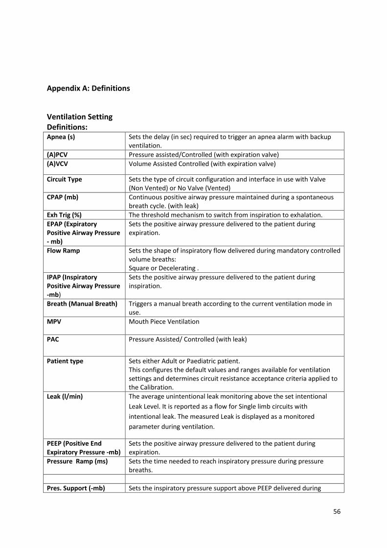
56
Appendix A: Definitions
Ventilation Setting Definitions: Apnea (s) Sets the delay (in sec) required to trigger an apnea alarm with backup
ventilation.
(A)PCV Pressure assisted/Controlled (with expiration valve)
(A)VCV Volume Assisted Controlled (with expiration valve)
Circuit Type Sets the type of circuit configuration and interface in use with Valve (Non Vented) or No Valve (Vented)
CPAP (mb) Continuous positive airway pressure maintained during a spontaneous breath cycle. (with leak)
Exh Trig (%) The threshold mechanism to switch from inspiration to exhalation.
EPAP (Expiratory Positive Airway Pressure - mb)
Sets the positive airway pressure delivered to the patient during expiration.
Flow Ramp Sets the shape of inspiratory flow delivered during mandatory controlled volume breaths: Square or Decelerating .
IPAP (Inspiratory Positive Airway Pressure -mb)
Sets the positive airway pressure delivered to the patient during inspiration.
Breath (Manual Breath) Triggers a manual breath according to the current ventilation mode in use.
MPV
Mouth Piece Ventilation
PAC
Pressure Assisted/ Controlled (with leak)
Patient type Sets either Adult or Paediatric patient. This configures the default values and ranges available for ventilation settings and determines circuit resistance acceptance criteria applied to the Calibration.
Leak (l/min) The average unintentional leak monitoring above the set intentional
Leak Level. It is reported as a flow for Single limb circuits with
intentional leak. The measured Leak is displayed as a monitored
parameter during ventilation.
PEEP (Positive End Expiratory Pressure -mb)
Sets the positive airway pressure delivered to the patient during expiration.
Pressure Ramp (ms) Sets the time needed to reach inspiratory pressure during pressure breaths.
Pres. Support (-mb) Sets the inspiratory pressure support above PEEP delivered during

57
Pressure Support Ventilation mode (spontaneous breaths).
Pres. Sup. Max (mb) Sets the maximum pressure support above PEEP allowed to achieve safe tidal volume in PSV VT mode.
Pres. Control. (Pressure Controlled - mb)
Sets the pressure control above PEEP delivered during inspiration for pressure controlled breaths (with constant I Time).
PSV Pressure support Ventilation (with expiration valve)
PSV VT Pressure support ventilation Volume regulated (with expiratory valve)
P-SIMV Pressure Synchroneous intermittent Mandatory Ventilation (with expiratory valve)
Rate (C/min) Sets the breaths per minute (bpm) to be delivered by the ventilator to the patient. The measured respiratory rate may be greater due to manual breaths.
ST Synchronised Timed (with leak)
I Time (s) Sets the duration of the inspiratory phase of a breath.
I Time Max (Maximum inspiratory time - s)
Sets the maximum duration of the inspiratory phase of a breath. AUTO / 0.3-2.5
I Time Min (Minimum Inspiratory Time - s)
Sets the minimum duration of the inspiratory phase of a breath.
Inspiration Trigger (I Trigger)
Sets the trigger threshold to be detected to deliver a new breath. The trigger is blocked for the first 300 ms (Pediatric) or 500 ms (Adult) following the beginning of expiration phase.
V-SIMV
Volume Synchroneous intermittent Mandatory Ventilation (with expiratory Valve)
Vt (Tidal Volume - ml)
Sets the volume of gas, to be delivered to the patient in during the inspiratory phase of controlled volume breath in (A)VCV, MPV, PSV VT or VTS modes.
VTS
Volume Target Synchronised (with leak)
Measured and calculated parameter definitions:
These measured and calculated parameters are displayed during configuration or during ventilation. Each ventilation mode sets out the parameters displayed.
FiO2 % Fraction of inspired Oxygen delivered to Patient circuit.
I / E The time ratio of the inspiratory period to the expiratory period. The measured I / E ratio is displayed as a monitored parameter during ventilation. Relative I / E ratio value is calculated and displayed during settings of time variables like Respiratory rate or Ti.
Leak Level (l/min) Level of intentional leak set in the patient configuration menu. Leak
monitoring displays leak above this set level.
MV (Delivered Minute
The measured volume averaged over the last breath. The measured MV is displayed as a monitored parameter during ventilation

58
Volume)
Pressure The measured airway pressure at the patient inlet port. The measured Pressure is displayed in the monitoring menu during ventilation
PEEP(Positive End Expiratory pressure -mb)
The airway pressure measured 100 ms at the end of the last expiration. The measured PEEP is displayed in the monitoring menu during ventilation.
Pmean Mean airway pressure in the Patient circuit computed over the last breath.
PIP (Peak Inspiratory Pressure -mb)
The maximum airway pressure reached over the last inspiration. The measured PIP is displayed in the monitoring menu during ventilation
Heart rate When a pulse oximeter is connected on the ventilator Pulse rate is displayed in the monitoring menu during ventilation.
Total Breath Rate (RR) (Res. Rate - c/min)
Breath rate is computed over the last breath according to (60/inspiratory time + Expiratory time ). The measured Rtot is displayed in the monitoring menu during ventilation.
SpO2 (Measured Oxygen Saturation %)
When a pulse oximeter is connected on the ventilator, SpO2 is displayed in the monitoring menu during ventilation.
Te (Expiratory time -s)
The duration in seconds of the last expiratory phase. The measured Te is displayed in the monitoring menu during ventilation.
Ti (Inspiratory time -s)
The duration in seconds of the last inspiratory phase. The measured Ti is displayed in the monitoring menu during ventilation.
Exhalation Tidal Volume (VTE -ml)
The expired volume measured over the last breath. Vte is displayed in the monitoring menu during ventilation.
Inspiratory Tidal Volume (VTI- ml)
The inspired volume measured over the last breath. Vti is displayed in the monitoring menu during ventilation.
OTHER Definitions
IP22 Ingress protection level
IP2X protects against the ingress of solid objects with >12.5 mm diameter.(e.g. fingers)
IPX2 protects against the ingress of water droplets (at 15° angle tilt)

59
2015 EOVE. All rights reserved. Made in France.
EOVE
4 rue Jules Ferry,
64000 Pau France
www.eove.fr
T +33 05 59 21 86 84
Part number 10015001 Rev X1