environmentalhealth perspectives processing of …...processing of plastics by albert spaak* an...
TRANSCRIPT
Environmental Health PerspectivesVol. 11, pp. 21-28, 1975
Processing of Plasticsby Albert Spaak*
An overview is given of the processing of plastic materials from the handling ofpolymers in the pellet and powder form to manufacturing of a plastic fabricatedproduct. Various types of equipment used and melt processing ranges of variouspolymer formulations to make the myriad of plastic products that are commerciallyavailable are discussed.
In a recent report issued by the StamfordResearch Institute (1), plastics consumptionby the year 2000 was forecast at 227 X 109 lb.This represents roughly a tenfold increase over1972 sales (Table 1). This is estimated at anannual growth rate of 8.1%o for the rest ofthis century.
This report outlines briefly the handling andthe processing of polymeric materials. Onlysome of the most basic processing methods arediscussed, since each major processing areahas specific variations used by specific manu-facturing organizations to meet the needs oftheir markets.Most of the material in this report has been
covered in detail and is available in the tradeliterature (2, 3).
Material HandlingFederal and state laws are not the only rea-
son that processors have automated their ma-terial handling requirements. Automated ma-terial flow systems are attractive to processorsbecause it reduces labor and avoids spills andother inefficiencies that increase costs.
Polymeric materials can be purchased in avariety of shipping containers, such as multi-wall paper bags, paper drum containers, metaland plastic drum containers, skidded boxes,
* Plastics Institute of America, Stevens Institute ofTechnology, Hoboken, New Jersey 07030.
bulk truck deliveries, and dry flow railroadhopper cars.
Processors using polymeric materials are noexception to the profit-motivated move to bulkbuying of raw materials and automatic, con-tamination-free conveying systems. They knowthat exposing their raw materials to atmos-phere is wasteful as well as hazardous.
Bulk plastics can be received in self-unload-ing bulk truck shipments or in larger amountsvia bulk dry flow rail cars. Received materialsare stored outside the processing plant in largeoutdoor silos equipped with filtering vents thatmeet stringent air pollution codes.Vacuum pumps unload bulk truck and rail
cars into the storage silos. A distribution boxat the bottom of the silo provides material flowdirection to any number of processing locationsinside the plant.
In-plant blending, especially of powderedmaterials, is rapidly growing in popularity be-cause custom blends are difficult to buy due toresin shortages. In such systems, raw materi-als, the basic resins are received in bulk, storedin a silo, and drawn into the blending areawhen needed for custom mixing. From theblender mixed materials flow in tubes auto-matically and directly to the processing lines.Automatic weighing and flow controls assure
quality and uniformity without manual labor.Ultrasophisticated systems will even add the
chemical additives automatically so that mate-rials are never exposed from storage to theprocessing line.
June 1975 21
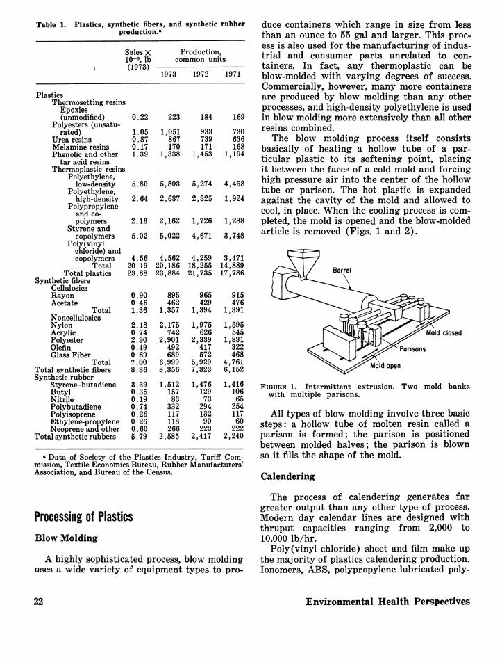
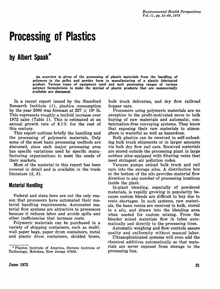
Table 1. Plastics, synthetic fibers, and synthetic rubberproduction.,
Sales X Production,10-9, lb common units(1973)
1973 1972 1971
PlasticsThermosetting resins
Epoxies(unmodified)
Polyesters (unsatu-rated)
Urea resinsMelamine resinsPhenolic and other
tar acid resinsThermoplastic resins
Polyethylene,low-density
Polyethylene,high-density
Polypropyleneand co-polymers
Styrene andcopolymers
Poly(vinylchloride) andcopolymers
TotalTotal plastics
Synthetic fibersCellulosicsRayonAcetate
TotalNoncellulosicsNylonAcrylicPolyesterOlefinGlass Fiber
TotalTotal synthetic fibersSynthetic rubber
Styrene-butadieneButylNitrilePolybutadienePolyisopreneEthylene-propyleneNeoprene and other
Total synthetic rubbers
0.22
1.050.870.171.39
223
1,051867170
1,338
5.80 5,803
2.64 2,637
2.16 2,162
5.02 5,022
184
933739171
1,453
5,274
2,325
1,726
4,671
169
730636168
1,194
4,458
1,924
1,288
3,748
4.56 4,562 4,259 3,47120.19 20,186 18,255 14,88923.88 23,884 21,735 17,786
0.900.461.36
2.180.742.900.490.697.008.36
3.390.350.190.740.260.260.605.79
895462
1,357
2,175742
2,901492689
6,9998,356
1,51215783
332117118266
2,585
965429
1,394
1,975626
2,339417572
5,9297,323
1,47612973
29413290223
2,417
915476
1,391
1,595545
1,831322468
4,7616,152
1,41610665
25411760
2222,240
* Data of Society of the Plastics Industry, Tariff Com-mission, Textile Economics Bureau, Rubber Manufacturers'Association, and Bureau of the Census.
duce containers which range in size from lessthan an ounce to 55 gal and larger. This proc-ess is also used for the manufacturing of indus-trial and consumer parts unrelated to con-tainers. In fact, any thermoplastic can beblow-molded with varying degrees of success.Commercially, however, many more containersare produced by blow molding than any otherprocesses, and high-density polyethylene is usedin blow molding more extensively than all otherresins combined.The blow molding process itself consists
basically of heating a hollow tube of a par-ticular plastic to its softening point, placingit between the faces of a cold mold and forcinghigh pressure air into the center of the hollowtube or parison. The hot plastic is expandedagainst the cavity of the mold and allowed tocool, in place. When the cooling process is com-pleted, the mold is opened and the blow-moldedarticle is removed (Figs. 1 and 2).
Mold closed
Mold open
FIGURE 1. Intermittent extrusion. Two mold bankswith multiple parisons.
All types of blow molding involve three basicsteps: a hollow tube of molten resin called aparison is formed; the parison is positionedbetween molded halves; the parison is blownso it fills the shape of the mold.
Calendering
Processing of PlasticsBlow Molding
A highly sophisticated process, blow moldinguses a wide variety of equipment types to pro-
The process of calendering generates fargreater output than any other type of process.Modern day calendar lines are designed withthruput capacities ranging from 2,000 to10,000 lb/hr.
Poly(vinyl chloride) sheet and film make upthe majority of plastics calendering production.Ionomers, ABS, polypropylene lubricated poly-
Environmental Health Perspectives22
blowing and cooling
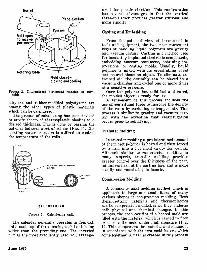
FIGURE 2. Intermittent horizontal rotation of turn-table.
ethylene and rubber-modified polystyrene areamong the other types of plastic materialswhich can be calendered.The process of calendering has been devised
to create sheets of thermoplastic plastics to adesired thickness. This is done by passing thepolymer between a set of rollers (Fig. 3). Cir-culating water or steam is utilized to controlthe temperature of the rolls.
CAUMAMIP PLASTIC uSHlUfNG
Soul'n
CALENOERING
FIGURE 3. Calendering unit.
The calender generally operates in four-rollunits made up of three banks, each bank beingwider than the preceding one. The inverted"L" is the most frequently used roll arrange-
ment for plastic sheeting. This configurationhas several advantages in that the verticalthree-roll stack provides greater stiffness andmore rigidity.
Casting and Embedding
From the point of view of investment intools and equipment, the two most convenientways of handling liquid polymers are gravityand vacuum casting. Casting is a method usedfor insulating implanted electronic components,embedding museum specimens, obtaining im-pressions, or casting molds. Usually, liquidpolymer is mixed with its crosslinking agentand poured about on object. To eliminate en-trained air, the assembly can be placed in avacuum chamber and cycled one or more timesat a negative pressure.Once the polymer has solidified and cured,
the molded object is ready for use.A refinement of this process includes the
use of centrifugal force to increase the densityof the resin by excluding entrapped air. Thisprocess is similar to gravity and vacuum cast-ing with the exception that centrifugationoccurs prior to solidifying.
Transfer Molding
In transfer molding a predetermined amountof thermoset polymer is heated and then forcedby a ram into a hot mold cavity for curing.Although similar to compression molding inmany respects, transfer molding providesgreater control over the thickness of the part,minimizes flash at the parting line, and is morereadily accommodating to inserts.
Compression Molding
A commonly used molding method which isapplicable to large and small items of manyvarious shapes is compression molding. Boththermosetting materials and thermoplasticscan be compression-molded, since they undergoboth physical and chemical changes. In thisprocess, the open cavities of a heated mold arefilled with the material which is caused to flowby closing the mold under high pressure (Fig.4). This compresses the material and shapes itin accordance with the two mold halves whichcome together. A flash is created in this process
June 1975 23

Positive mold Semi-positive mold
FIGURE 4. Three types of compression molds.
since excess material must escape at the partingline.
Coating
There are two methods of coating which arein general use. In the first method, webs or
Typical ronge of specificationsWeb width-45-60 in.Line speed -500-1500ft./min.Extruder capocity-1200-2600 lb./hr.
4'V2-28:1 6-28:1Extruder Auxiliory unwind Extruder
other substrates are coated with elastomericsor plastics from solutions. The substrate isgenerally fed through a solvated polymer bath,where the appropriate amount is applied andthen fed through a heated chamber, whichdrives off residual solvent and crosslinks thefilm.The second method of coating is extrusion
coating. In this method, molten thermoplasticsheet is discharged from a slotted die onto asubstrate or web of paper, cellophane, paperboard, polyester, or polyolefin material of ex-trusion coating. The coating substrates andmolten material are extrusion coated. The mov-ing substrates and molten plastics are thencombined in a nip between a rubber and chillroll and then wound into a roll form (Fig. 5).An item familiar to many people is the poly-ethylene-coated milk carton.
Unwind-flying splice Prime cooter- Extrusion laminator Post coaster/gravure printer Winder-flying transfergravure/flexo printer
FIGURE 5. Tandem coating on typical flexible packaging line.
Powder Coating
The early development of adequate and suit-able PVC materials was made possible largelythru the use of fiuidized bed for the applicationof thermoplastic materials. The early successesand broad use of the fluidized bed and the useof electrostatic spray has encouraged manu-facturers to offer additional material types.Some of these were earlier available as castingresins but they did require conversion to a
form suitable for powdered coating. Availabletoday are polyethylene, cellulose acetobutyrate,nylon, chlorinated polyethers, polytetrafluoro-ethylene, and polypropylene powders.
Thermoplastic materials can be used for pro-ducing heavy chemical and abrasion-resistantcoatings on wire goods. Most of the materials
applied before the introduction of the electro-static spray were of this character.A bed-fluidized plastic powder is created by
constructing a container which has an upperopen section and lower closed section, separatedby a porous plate. The plastic powder is placedon the porous plate in the top compartment.Air brought into the lower section flows upwardthrough the plate and powder. This fluidizes thepowder, giving it all the physical propertiesof a fluid in such an expanded quantity. Thepowder must be kept uniformly aerated byusing dry air and vibrating the bed.The part which is to be coated is heated to a
temperature above the fusion temperature ofthe powder. After heating, it is lowered intothe bed to a point below the upper expandedsurface of the powder. That powder which con-
Environmental Health Perspectives
Floshtip mo
24
tacts the hot surface fuses and attaches itselfto the part, which is manipulated while im-mersed so that all surfaces are equally exposed.When the part is withdrawn, any unused pow-der is dumped or blown from the part.The electrostatic powder process is similar,
but in this method the particles of coating aregiven an electric charge of one polarity and theitem which is to be coated is given a chargeof opposite polarity. When the two are broughtinto proximity, the electrical attraction whichexists causes the powder to accumulate on theitem's surface. The various equipment arrange-ments available are but different approaches tocharging and distributing the particles aboutthe article so the attraction can be effective.
Extrusion
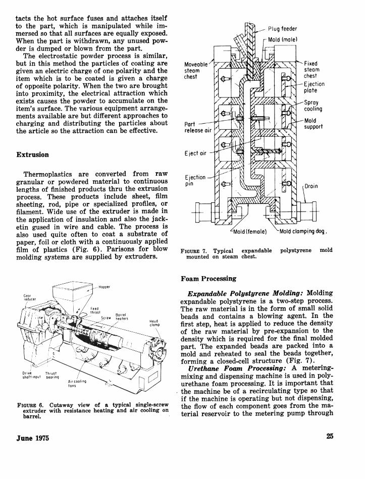
Thermoplastics are converted from rawgranular or powdered material to continuouslengths of finished products thru the extrusionprocess. These products include sheet, filmsheeting, rod, pipe or specialized profiles, orfilament. Wide use of the extruder is made inthe application of insulation and also the jack-etin gused in wire and cable. The process isalso used quite often to coat a substrate ofpaper, foil or cloth with a continuously appliedfilm of plastics (Fig. 6). Parisons for blowmolding systems are supplied by extruders.
FIGURE 7. Typical expandablemounted on steam chest.
polystyrene mold
Cutaway view of a typical single-screwwith resistance heating and air cooling on
Foam Processing
Expandable Polystyrene Molding: Moldingexpandable polystyrene is a two-step process.The raw material is in the form of small solidbeads and contains a blowing agent. In thefirst step, heat is applied to reduce the densityof the raw material by pre-expansion to thedensity which is required for the final moldedpart. The expanded beads are packed into amold and reheated to seal the beads together,forming a closed-cell structure (Fig. 7).
Urethane Foam Processing: A metering-mixing and dispensing machine is used in poly-urethane foam processing. It is important thatthe machine be of a recirculating type so thatif the machine is operating but not dispensing,the flow of each component goes from the ma-terial reservoir to the metering pump through
June 1975
FIGURE 6.extruderbarrel.
25

a heat exchanger to the mixing head.To be considered a high foam processing
machine, the equipment must be capable ofdelivering the components, such as a polyol andan isocyanate mixed at the proper ratio to amold or cavity. It is important that there iscapability for the components to all arrive atthe mixture simultaneously and at the correcttemperature to assure proper mixing and chem-ical reaction of the foam.Extruded Polystyrene Foam: A three
basic forms of polystyrene foam which areextruded are slab, sheet, and profiles. Poly-styrene foam is widely used primarily becauseof two attractive features: its low cost and itsoutstanding physical properties, i.e., attractiveappearance, thermal insulating qualities, cush-ioning ability, moisture resistance, and rigidity.Foam Melt Methods: While a number of
techniques are used to produce structural foamparts by injection molding or extruding afoamable melt, they must all have the availa-bility to produce, in a single step, a structureof solid outer skins and integral foam interior.In addition, they must all have, in varying de-grees, the ability to control wall thickness andfoam density.
There are three advantages in structuralfoam molding which should be mentioned:lightweight, structurally adequate parts withfinely, detailed surfaces can be produced; mostprocesses are low-pressure types from whichlarge parts can be processed with low-tonnagemachines and economical molds; a strength andeconomy superior to that of solid molding isavailable because the rigidity varies directlywith density.
Injection Molding
In injection molding, thermoplastic polymersare heated to a molten state and are forcedunder pressure into a relatively cooled moldwhere the polymer solidifies to form the object.The viscous liquid is normally injected into
the mold at pressures up to 20,000 psi. Theforce which is required to clamp the moldhalves together normally ranges from 1 to 5tons/in. of projected area of the part beingmolded. The tonnage required is influenced bythe dimensions of the part, the type of materialand the design of the part.Normal scrap generated in the injection
molding of thermoplastics materials can beground into small particles and reused. Thisadds to the economical features of the process.The products requiring intricate shapes and
tight tolerances most readily lend themselvesto injection molding. Thermoplastics, fast-cur-ing elastomers, and thermosetting resins can beinjection-molded.
There is a wide range of sizes and types ofinjection molding machines available. They canoffer manual, semiautomatic or automatic op-eration. Their size rating is determined by thequantity of material which can be injected inone cycle, which can range from a fraction of anounce in small laboratory models to severalpounds in large production machines.Two units comprise the injection molding
machine: one for opening and closing the moldand the other for injecting the plastic material.A hydraulic or toggle-operated moving platenand a stationary platen comprise the first half.The mold halves are fastened securely to theseplatens.A feed hopper, a controlled feeding device,
and a heated injection extrusion screw whichreciprocates to act as a plasticizer and plungercomprise the second half.
Various formulations of thermoplastics canbe supplied by manufacturers for the most effi-cient production and the most desirable prop-erties in the finished product. To be injection-molded, a plastic must have good flow proper-ties. Flow, as related to injection molding isdefined as the amount of travel a plastic ma-terial undergoes when it is subjected to heatand pressure.
Forging and Solid-Phase Forming
Complete melting of the material beforeforming has been involved in most commercialprocessing methods to date. Recently, however,forming of thermoplastics in a solid phase byapplying well established metal working tech-niques has been studied extensively.
Variously known as forging and phase form-ing, forging refers to fabrication by bulk defor-mation of material in constraining dies by ap-plication of force. It requires the steps shownin Figure 8.
Forging has a number of advantages: (1)it enables the processor to form parts as thickas 1 in. or more with reduced cycle time that is
Environmental Health Perspectives26
Forging operotion Removalof forgingfrom dies
\1 \ \ \ \ \\\
Top Finishingrop 1 * (if needed)
Plostic sheet \
I Ii * 4
Blonk (mode bycutting from an
extrusion or bysome oihertechnique)
Oven(dielectrvc or
other heating system)
7J Bottomdie
Election pin Forging
FIGURE 8. Schematic diagram of steps required inforging of plastics.
nearly independent of part thickness; (2) avail-able forging presses in metalworking forgeshops and compression molding presses canbe utilized; (3) hard-to-work materials suchas those with high molecular weight, those sus-
ceptable to rapid thermal degradation or ma-
terials with fillers and reinforcements can befeasibly forged; (4) products show improvedmechanical properties because of preferentialmolecular orientation; (5) increased economyin cost of equipment and reduction of toolingcost is also possible for production items.
MMold
y i -tI~
Seol-"
rlu sS wsw-V
Voc.
-I L -u1 AnA-- --
vl
Rotational Molding
Rotational molding is also called rotomoldingor rotocasting and differs from other techniquessuch as blow and injection molding in that hol-low items of any size or shape as well as soliditems can be readily made, and the resin meltsin the mold and does not require a driving pres-sure.
In rotational molding, rigid or resilient hol-low bodies are formed from powdered plasticmaterials or vinyl plastisols by being heatedand rotated simultaneously in two planes per-pendicular to each other. The plastic particlescontact, melt or fuse, as the case may be, on
the inner surfaces of the hot molds and buildup in thickness until all the material is fusedand the finished product is formed.The most popular rotomolding system uses
a horizontal rotating unit commonly called thecarousel. This normally has three arms onwhich molds are mounted.
Rotational molding can be classified thermo-dynamically as an unsteady heat transfer proc-ess; i.e., the mold temperature never reachesequilibrium and is constantly rising or fallingthroughout the entire cycle; therefore, the tem-
~~Thin corner:/ ~~ond edges
Formed port
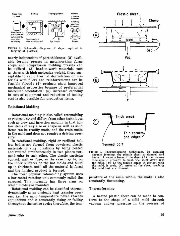
FIGURE 9. Thermoforming techniques. In straightvacuum forming, the plastic sheet is clamped andheated. A vacuum beneath the sheet (A) then causesatmospheric pressure to push the sheet down intothe mold. (B) as the plastic comes in contact withthe mold, it cools. (C) areas of the sheet reachingthe mold last are thinnest.
perature of the resin within the mold is alsoconstantly fluctuating.
Thermoforming
A heated plastic sheet can be made to con-form to the shape of a solid mold throughvacuum and/or pressure in the process of
June 1975
Preporationof blank
Heoting
Clomp
I
It O'
I0, I t
TV11 I .
27

thermoforming. Heated to a compliant state,the plastic sheet is then securely placed over asealed chamber containing the mold. The plas-tic is drawn over the mold when the vacuummaintained in a reservoir tank is opened (Fig.9).
There are many basic types of thermoform-ing techniques. The most common are the sin-gle-station and rotary sheet-fed machines. Oneheating station and one forming station com-prises the single-station machine; the rotarymachine is made up of one loading (sheet) andunloading (finishing part) station, one or two
heating stations, and one forming station.The rotary machine operates in a manner
similar to a merry-go-round owing to the factthat there is always a sheet in each of the threeor four stations, providing a considerablygreater output than a single station machine.
REFERENCES
1. Stamford Research Institute Report, 1973.2. Modern Plastics Encyclopedia, Vol. 50, No. 10A,
McGraw-Hill, New York, 1973-1974.3. Boretos, J. W., Course Guide to Biomedical Polymers,
Their Design, Fabrication and Molding. Charles CThomas, Springfield, Ill., 1973.
28 Environmental Health Perspectives