environmental protection - recreational aviation...
TRANSCRIPT
INTERNATIONAL STANDARDSAND RECOMMENDED PRACTICES
ENVIRONMENTALPROTECTION
ANNEX 16
TO THE CONVENTION ON INTERNATIONAL CIVIL AVIATION
VOLUME I
AIRCRAFT NOISE
THIRD EDITION — JULY 1993
This edition incorporates all amendments to Annex 16, adopted by the Council prior to 25 March 1993 and supersedes on 11 November 1993
all previous editions of the Annex.
For information regarding the applicability of the Standards andRecommended Practices, see Foreword and the relevant clauses
in each Chapter.
INTERNATIONAL CIVIL AVIATION ORGANIZATION

AMENDMENTS
The issue of amendments is announced regularly in the ICAO Journal and in themonthly Supplement to the Catalogue of ICAO Publications and Audio-visualTraining Aids, which holders of this publication should consult. The space belowis provided to keep a record of such amendments.
RECORD OF AMENDMENTS AND CORRIGENDA
AMENDMENTS CORRIGENDA
No.Date
applicableDate
enteredEntered
by No.Date
of issueDate
enteredEntered
by
1-4 Incorporated in this edition Erratum to Amdt. 5
5 6/11/97 21/7/97 11/2/99
6 4/11/99
(ii)

1112
13
313
131313
14
15
51515
15161617
19
20
02020
202021
22
22222
222223
TABLE OF CONTENTS
Page Page
Foreword . . . . . . . . . . . . . . . . . . . . . . . . . . . . . . . . . . . . . . . . . . . (v)
Part I. DEFINITIONS . . . . . . . . . . . . . . . . . . . . . . . . . . . . . . 1
Part II. AIRCRAFT NOISE CERTIFICATION . . . . . . . . 2
CHAPTER 1. Administration . . . . . . . . . . . . . . . . . . . . . . . . . 2
CHAPTER 2. Subsonic jet aeroplanes — applicationfor certificate of airworthiness for the prototypeaccepted before 6 October 1977. . . . . . . . . . . . . . . . . . . . . . . . . 3
2.1 Applicability . . . . . . . . . . . . . . . . . . . . . . . . . . . . . . . . . 32.2 Noise evaluation measure . . . . . . . . . . . . . . . . . . . . . . . 32.3 Noise measurement points . . . . . . . . . . . . . . . . . . . . . . 32.4 Maximum noise levels . . . . . . . . . . . . . . . . . . . . . . . . . 32.5 Trade-offs . . . . . . . . . . . . . . . . . . . . . . . . . . . . . . . . . . . 42.6 Test procedures . . . . . . . . . . . . . . . . . . . . . . . . . . . . . . . 4
CHAPTER 3.
1. Subsonic jet aeroplanes — application forcertificate of airworthiness for the prototypeaccepted on or after 6 October 1977
2. Propeller-driven aeroplanes over 5 700 kg —application for certificate of airworthinessfor the prototype accepted on or after1 January 1985 and before 17 November 1988
3. Propeller-driven aeroplanes over 8 618 kg —application for certificate of airworthinessfor the prototype accepted on or after17 November 1988 . . . . . . . . . . . . . . . . . . . . . . . . . . . . . . . . 5
3.1 Applicability . . . . . . . . . . . . . . . . . . . . . . . . . . . . . . . . . 53.2 Noise measurements . . . . . . . . . . . . . . . . . . . . . . . . . . . 53.3 Reference noise measurement points . . . . . . . . . . . . . . 53.4 Maximum noise levels . . . . . . . . . . . . . . . . . . . . . . . . . 63.5 Trade-offs . . . . . . . . . . . . . . . . . . . . . . . . . . . . . . . . . . . 63.6 Noise certification reference procedures . . . . . . . . . . . 73.7 Test procedures . . . . . . . . . . . . . . . . . . . . . . . . . . . . . . . 8
CHAPTER 4. Supersonic aeroplanes . . . . . . . . . . . . . . . . . . . 9
4.1 Supersonic aeroplanes — application forcertificate of airworthiness for the prototypeaccepted before 1 January 1975 . . . . . . . . . . . . . . . . . . 9
4.2 Supersonic aeroplanes — application forcertificate of airworthiness for the prototypeaccepted on or after 1 January 1975 . . . . . . . . . . . . . . 9
CHAPTER 5. Propeller-driven aeroplanes over 5 700 kg — application for certificate of airworthiness for the prototype accepted before 1 January 1985 . . . . . . . . . . . . . 10
5.1 Applicability . . . . . . . . . . . . . . . . . . . . . . . . . . . . . . . . . 105.2 Noise measurements . . . . . . . . . . . . . . . . . . . . . . . . . . . 105.3 Reference noise measurement points . . . . . . . . . . . . . . 105.4 Maximum noise levels . . . . . . . . . . . . . . . . . . . . . . . . . 115.5 Trade-offs . . . . . . . . . . . . . . . . . . . . . . . . . . . . . . . . . . . 11
5.6 Noise certification reference procedures . . . . . . . . . . .5.7 Test procedures . . . . . . . . . . . . . . . . . . . . . . . . . . . . . . .
CHAPTER 6. Propeller-driven aeroplanes not exceeding 8 618 kg — application for certificate of airworthiness for the prototype accepted before 17 November 1988 . . . . . . . . . . . . . . . . . . . . . . . . . . . . . . . . . . .
6.1 Applicability . . . . . . . . . . . . . . . . . . . . . . . . . . . . . . . . . 16.2 Noise evaluation measure . . . . . . . . . . . . . . . . . . . . . . .6.3 Maximum noise levels . . . . . . . . . . . . . . . . . . . . . . . . .6.4 Noise certification reference procedures . . . . . . . . . . .6.5 Test procedures . . . . . . . . . . . . . . . . . . . . . . . . . . . . . . .
CHAPTER 7. Propeller-driven STOL aeroplanes. . . . . . . . . .
CHAPTER 8. Helicopters . . . . . . . . . . . . . . . . . . . . . . . . . . . .
8.1 Applicability . . . . . . . . . . . . . . . . . . . . . . . . . . . . . . . . . 18.2 Noise evaluation measure . . . . . . . . . . . . . . . . . . . . . . .8.3 Reference noise measurement points . . . . . . . . . . . . . .8.4 Maximum noise levels . . . . . . . . . . . . . . . . . . . . . . . . .8.5 Trade-offs . . . . . . . . . . . . . . . . . . . . . . . . . . . . . . . . . . .8.6 Noise certification reference procedures . . . . . . . . . . .8.7 Test procedures . . . . . . . . . . . . . . . . . . . . . . . . . . . . . . .
CHAPTER 9. Installed auxiliary power units (APU) and associated aircraft systems during ground operations . . . . . . . . . . . . . . . . . . . . . . . . . . . . . . . . . . . . . . . . . .
CHAPTER 10. Propeller-driven aeroplanes not exceeding 8 618 kg — application for certificate of airworthiness for the prototype or derived version accepted on or after 17 November 1988 . . . . . . . . . . . . . . . . . .
10.1 Applicability. . . . . . . . . . . . . . . . . . . . . . . . . . . . . . . . 210.2 Noise evaluation measure . . . . . . . . . . . . . . . . . . . . .10.3 Reference noise measurement points . . . . . . . . . . . .10.4 Maximum noise levels . . . . . . . . . . . . . . . . . . . . . . . .10.5 Noise certification reference procedures . . . . . . . . . .10.6 Test procedures . . . . . . . . . . . . . . . . . . . . . . . . . . . . .
CHAPTER 11. Helicopters not exceeding 2 730 kgmaximum certificated take-off mass . . . . . . . . . . . . . . . . . . . . .
11.1 Applicability. . . . . . . . . . . . . . . . . . . . . . . . . . . . . . . . 211.2 Noise evaluation measure . . . . . . . . . . . . . . . . . . . . .11.3 Reference noise measurement point . . . . . . . . . . . . .11.4 Maximum noise level. . . . . . . . . . . . . . . . . . . . . . . . .11.5 Noise certification reference procedure. . . . . . . . . . .11.6 Test procedures . . . . . . . . . . . . . . . . . . . . . . . . . . . . .
Part III. NOISE MEASUREMENT FORMONITORING PURPOSES . . . . . . . . . . . . . . . . . . . . . . . . . . 24
Part IV. ASSESSMENT OF AIRPORT NOISE. . . . . . . . . 25
Part V. CRITERIA FOR THE APPLICATION OFNOISE ABATEMENT OPERATING PROCEDURES . . . . 26
ANNEX 16 — VOLUME I (iii) 7/11/966/11/97
No. 5

Annex 16 — Environmental Protection Volume I
Page Page
97
97
978
9899
0
01
010101
03
104
04
045
0506
8
111
13
115
121
122
APPENDICES
APPENDIX 1. Evaluation method for noise certificationof subsonic jet aeroplanes — application for certificateof airworthiness for the prototype accepted before6 October 1977 . . . . . . . . . . . . . . . . . . . . . . . . . . . . . . . . . . . . . . 27
1. Introduction . . . . . . . . . . . . . . . . . . . . . . . . . . . . . . . . . . 272. Noise certification test and measurement
conditions . . . . . . . . . . . . . . . . . . . . . . . . . . . . . . . . . . . 273. Measurement of aeroplane noise received
on the ground . . . . . . . . . . . . . . . . . . . . . . . . . . . . . . . . 294. Calculation of effective perceived noise
level from measured noise data . . . . . . . . . . . . . . . . . . 305. Reporting of data to the certificating
authority and correcting measured data . . . . . . . . . . . . 386. Nomenclature . . . . . . . . . . . . . . . . . . . . . . . . . . . . . . . . 407. Mathematical formulation of noy tables . . . . . . . . . . . 438. Sound attenuation in air . . . . . . . . . . . . . . . . . . . . . . . . 449. Detailed correction procedures . . . . . . . . . . . . . . . . . . . 52
APPENDIX 2. Evaluation method for noisecertification of:
1. Subsonic jet aeroplanes — application forcertificate of airworthiness for the prototypeaccepted on or after 6 October 1977
2. Propeller-driven aeroplanes over 5 700 kg —application for certificate of airworthinessfor the prototype accepted on or after1 January 1985 and before 17 November 1988
3. Propeller-driven aeroplanes over 8 618 kg —application for certificate of airworthiness for theprototype accepted on or after 17 November 1988
4. Helicopters . . . . . . . . . . . . . . . . . . . . . . . . . . . . . . . . . . . . . . 61
1. Introduction . . . . . . . . . . . . . . . . . . . . . . . . . . . . . . . . . . 612. Noise certification test and measurement
conditions . . . . . . . . . . . . . . . . . . . . . . . . . . . . . . . . . . . 613. Measurement of aircraft noise received
on the ground . . . . . . . . . . . . . . . . . . . . . . . . . . . . . . . . 634. Calculation of effective perceived
noise level from measured noise data . . . . . . . . . . . . . 675. Reporting of data to the certificating authority . . . . . . 726. Nomenclature: symbols and units . . . . . . . . . . . . . . . . 747. Sound attenuation in air . . . . . . . . . . . . . . . . . . . . . . . . 778. Adjustment of helicopter flight test results . . . . . . . . . 779. Adjustment of aeroplane flight test results . . . . . . . . . 84
APPENDIX 3. Noise evaluation method for noisecertification of propeller-driven aeroplanes not exceeding8 618 kg — application for certificate of airworthinessfor the prototype accepted before 17 November 1988 . . . . . . . 93
1. Introduction . . . . . . . . . . . . . . . . . . . . . . . . . . . . . . . . . . 932. Noise certification test and measurement
conditions . . . . . . . . . . . . . . . . . . . . . . . . . . . . . . . . . . . 933. Measurement of aeroplane noise received
on the ground . . . . . . . . . . . . . . . . . . . . . . . . . . . . . . . . 934. Reporting of data to the certificating
authority and correction of measured data. . . . . . . . . . 95
APPENDIX 4. Evaluation method for noise certificationof helicopters not exceeding 2 730 kg maximumcertificated take-off mass . . . . . . . . . . . . . . . . . . . . . . . . . . . . . .
1. Introduction. . . . . . . . . . . . . . . . . . . . . . . . . . . . . . . . . .2. Noise certification test and measurement
conditions . . . . . . . . . . . . . . . . . . . . . . . . . . . . . . . . . . .3. Noise unit definition . . . . . . . . . . . . . . . . . . . . . . . . . . . 94. Measurement of helicopter noise received
on the ground . . . . . . . . . . . . . . . . . . . . . . . . . . . . . . . .5. Adjustment to test results . . . . . . . . . . . . . . . . . . . . . . .6. Reporting of data to the certificating
authority and validity of results . . . . . . . . . . . . . . . . . . 10
APPENDIX 5. Monitoring aircraft noise on and inthe vicinity of aerodromes . . . . . . . . . . . . . . . . . . . . . . . . . . . . . 1
1. Introduction. . . . . . . . . . . . . . . . . . . . . . . . . . . . . . . . . . 12. Definition . . . . . . . . . . . . . . . . . . . . . . . . . . . . . . . . . . . 13. Measurement equipment. . . . . . . . . . . . . . . . . . . . . . . . 14. Field equipment installation . . . . . . . . . . . . . . . . . . . . . 1
APPENDIX 6. Noise evaluation method for noisecertification of propeller-driven aeroplanes notexceeding 8 618 kg — application for certificate ofairworthiness for the prototype accepted on or after17 November 1988 . . . . . . . . . . . . . . . . . . . . . . . . . . . . . . . . . . .
1. Introduction. . . . . . . . . . . . . . . . . . . . . . . . . . . . . . . . . . 12. Noise certification test and measurement
conditions . . . . . . . . . . . . . . . . . . . . . . . . . . . . . . . . . . . 13. Noise unit definition . . . . . . . . . . . . . . . . . . . . . . . . . . . 104. Measurement of aeroplane noise received
on the ground . . . . . . . . . . . . . . . . . . . . . . . . . . . . . . . . 15. Adjustment to test results . . . . . . . . . . . . . . . . . . . . . . . 16. Reporting of data to the certificating
authority and validity of results . . . . . . . . . . . . . . . . . . 10
ATTACHMENTS
ATTACHMENT A. Equations for the calculation ofnoise levels as a function of take-off mass . . . . . . . . . . . . . . . .
ATTACHMENT B. Guidelines for noise certification of propeller-driven STOL aeroplanes. . . . . . . . . . . . . . . . . . . . . 1
ATTACHMENT C. Guidelines for noise certification of installed auxiliary power units (APU) andassociated aircraft systems during ground operation. . . . . . . . .
ATTACHMENT D. Guidelines for evaluating analternative method of measuring helicopternoise during approach. . . . . . . . . . . . . . . . . . . . . . . . . . . . . . . . .
ATTACHMENT E. Applicability of ICAOAnnex 16 noise certification standardsfor propeller-driven aeroplanes. . . . . . . . . . . . . . . . . . . . . . . . . .
7/11/96 (iv)6/11/97
No. 5

ialsinese:
e;
nt
on
fornt
ofext
edns,ctst.
5,asld
IIne
ach
FOREWORD
Historical background
Standards and Recommended Practices for Aircraft Noisewere first adopted by the Council on 2 April 1971 pursuant tothe provisions of Article 37 of the Convention on InternationalCivil Aviation (Chicago, 1944) and designated as Annex 16 tothe Convention. The Annex was developed in the followingmanner:
The Sixteenth Session of the Assembly, Buenos Aires,September 1968, adopted the following Resolution:
A16-3: Aircraft Noise in the Vicinity of Airports
Whereas the problem of aircraft noise is so serious in thevicinity of many of the world’s airports that public reaction ismounting to a degree that gives cause for great concern andrequires urgent solution;
Whereas the noise that concerns the public and civil aviationtoday is being caused by increase in traffic of existing aircraft;
Whereas the introduction of future aircraft types could increaseand aggravate this noise unless action is taken to alleviate thesituation;
Whereas the Fifth Air Navigation Conference of ICAO heldin Montreal in November 1967 made certain recommenda-tions, based on the principal conclusions of the InternationalConference on the Reduction of Noise and DisturbanceCaused by Civil Aircraft (“The London Noise Conference”)held in London in November 1966, with the object ofreaching international solutions to the problem through themachinery of ICAO; and
Whereas the Assembly has noted the action being taken by theCouncil, in consultation with States and the appropriateinternational organizations, to give effect to the recommenda-tions of the Fifth Air Navigation Conference, as reported tothe Assembly by the Secretary General;
THE ASSEMBLY RESOLVES to instruct the Council:
1) to call an international conference within the machinery ofICAO as soon as practicable, bearing in mind the need foradequate preparation, to consider the problem of aircraftnoise in the vicinity of airports;
2) to establish international specifications and associatedguidance material relating to aircraft noise;
3) to include, in appropriate existing Annexes and otherrelevant ICAO documents and possibly in a separate
Annex on noise, such material as the description andmethods of measurement of aircraft noise and suit-able limitations on the noise caused by aircraft thatis of concern to communities in the vicinity of airports;and
4) to publish such material on a progressive basis,commencing at the earliest possible time.
In response to Assembly Resolution A16-3, a SpecMeeting on Aircraft Noise in the Vicinity of Aerodromes waconvened in Montreal (November-December 1969) to examthe following aspects related to the problems of aircraft noi
a) procedures for describing and measuring aircraft nois
b) human tolerance to aircraft noise;
c) aircraft noise certification;
d) criteria for establishment of aircraft noise abatemeoperating procedures;
e) land use control; and
f) ground run-up noise abatement procedures.
Based on the recommendations of the Special MeetingAircraft Noise in the Vicinity of Aerodromes, draftInternational Standards and Recommended Practices Aircraft Noise were developed and, after amendmefollowing the usual consultation with the Contracting Statesthe Organization, were adopted by the Council to form the tof this Annex.
With the development of Standards and RecommendPractices dealing with the control of aircraft engine emissioit was felt that all provisions relating to environmental aspeof aviation should be included into a single documenAccordingly, as part of the Resolution adopting Amendmentit was agreed that Annex 16 should be retitled “Environmental Protection” and Volume I of the Annex shoucontain the existing provisions (Third Edition) of Annex 16 —Aircraft Noise as amended by Amendment 5 and Volume should contain the provisions related to aircraft engiemissions.
Table A shows the origin of amendments together withlist of the principal subjets involved and the dates on whi
ANNEX 16 — VOLUME I (v) 11/11/93
Annex 16 — Environmental Protection Volume I
inthef atheatirexon,
alley
n.
e,ofor
hhf
l,m
hefgth
lyscil.
dlf-dn
achhethe
the Annex and the amendments were adopted by the Council,when they became effective and when they becameapplicable.
Applicability
Part I of Volume I of Annex 16 contains definitions andPart II contains Standards, Recommended Practices andguidelines for noise certification applicable to theclassification of aircraft specified in individual Chapters ofthat Part, where such aircraft are engaged in international airnavigation.
Note.— Chapters 2 and 3 exclude jet aeroplanes havingshort take-off and landing (STOL) capabilities which, pendingthe development by ICAO of a suitable definition, aredescribed for the purpose of this Annex as those requiring arunway (with no stopway or clearway) of 610 m or less at themaximum certificated mass for airworthiness.
Parts III, IV and V of Volume I of Annex 16 containRecommended Practices and guidance material for use byStates with a view to promoting uniformity in measurement ofnoise for monitoring purposes, use of an international noiseexposure reference unit for land use planning, andestablishment of noise abatement operating procedures.
Action by Contracting States
Notification of differences. The attention of Contracting Statesis drawn to the obligation imposed by Article 38 of theConvention by which Contracting States are required to notifythe Organization of any differences between their nationalregulations and practices and the International Standardscontained in this Annex and any amendments thereto.Contracting States are invited to extend such notification toany differences from the Recommended Practices contained inthis Annex, and any amendments thereto, when the notificationof such differences is important for the safety of air navigation.Further, Contracting States are invited to keep the Organizationcurrently informed of any differences which may subsequentlyoccur, or of the withdrawal of any differences previouslynotified. A specific request for notification of differences willbe sent to Contracting States immediately after the adoption ofeach amendment to this Annex.
The attention of States is also drawn to the provisions ofAnnex 15 related to the publication of differences betweentheir national regulations and practices and the related ICAOStandards and Recommended Practices through the Aeronau-tical Information Service, in addition to the obligation ofStates under Article 38 of the Convention.
Use of the Annex text in national regulations. TheCouncil, on 13 April 1948, adopted a resolution inviting the
attention of Contracting States to the desirability of using their own national regulations, as far as is practicable, precise language of those ICAO Standards that are oregulatory character and also of indicating departures from Standards, including any additional national regulations thwere important for the safety or regularity of international anavigation. Wherever possible, the provisions of this Annhave been written in such a way as to facilitate incorporatiwithout major textual changes, into national legislation.
Status of Annexcomponents
An Annex is made up of the following component parts, not of which, however, are necessarily found in every Annex; thhave the status indicated:
1.— Material comprising the Annex proper:
a) Standards and Recommended Practices adopted bythe Council under the provisions of the ConventioThey are defined as follows:
Standard: Any specification for physicalcharacteristics, configuration, matériel, performancpersonnel or procedure, the uniform application which is recognized as necessary for the safety regularity of international air navigation and to whicContracting States will conform in accordance witthe Convention; in the event of impossibility ocompliance, notification to the Council iscompulsory under Article 38.
Recommended Practice: Any specification forphysical characteristics, configuration, matérieperformance, personnel or procedure, the uniforapplication of which is recognized as desirable in tinterest of safety, regularity or efficiency ointernational air navigation, and to which ContractinStates will endeavour to conform in accordance withe Convention.
b) Appendices comprising material grouped separatefor convenience but forming part of the Standardand Recommended Practices adopted by the Coun
c) Provisions governing the applicability of theStandards and Recommended Practices.
d) Definitions of terms used in the Standards anRecommended Practices which are not seexplanatory in that they do not have acceptedictionary meanings. A definition does not have aindependent status but is an essential part of eStandard and Recommended Practice in which tterm is used, since a change in the meaning of term would affect the specification.
11/11/93 (vi)

Foreword Annex 16 — Environmental Protection
s
he
gns:ed”.
inasilvenits. thatay,is
isat
ivethehest
irectces-ts inhe
2.— Material approved by the Council for publication inassociation with the Standards and RecommendedPractices:
a) Forewords comprising historical and explanatorymaterial based on the action of the Council andincluding an explanation of the obligations of Stateswith regard to the application of the Standards andRecommended Practices ensuing from the Conventionand the Resolution of Adoption.
b) Introductions comprising explanatory materialintroduced at the beginning of parts, chapters or sectionsof the Annex to assist in the understanding of theapplication of the text.
c) Notes included in the text, where appropriate, to givefactual information or references bearing on theStandards or Recommended Practices in question, butnot constituting part of the Standards or RecommendedPractices.
d) Attachments comprising material supplementary to theStandards and Recommended Practices, or included as aguide to their application.
Selection of language
This Annex has been adopted in four languages — English,French, Russian and Spanish. Each Contracting State isrequested to select one of those texts for the purpose ofnational implementation and for other effects provided for inthe Convention, either through direct use or through trans-lation into its own national language, and to notify theOrganization accordingly.
Editorial practices
The following practice has been adhered to in order toindicate at a glance the status of each statement: Standards
have been printed in light face roman; RecommendedPractices have been printed in light face italics, the statubeing indicated by the prefix Recommendation; Notes havebeen printed in light italics, the status being indicated by tprefix Note.
It is to be noted that in the English text the followinpractice has been adhered to when writing the specificatioStandards employ the operative verb “shall” whilRecommended Practices employ the operative verb “shoul
The units of measurement used in this document areaccordance with the International System of Units (SI) specified in Annex 5 to the Convention on International CivAviation. Where Annex 5 permits the use of non-SI alternatiunits these are shown in parentheses following the basic uWhere two sets of units are quoted it must not be assumedthe pairs of values are equal and interchangeable. It mhowever, be inferred that an equivalent level of safety achieved when either set of units is used exclusively.
Any reference to a portion of this document which identified by a number includes all subdivisions of thportion.
Co-ordination with ISO activity
In the provisions related to certification procedures, extensuse is made of the related specifications developed by International Organization for Standardization (ISO) and tCommission électrotechnique Internationale (IEC). In mocases these specifications have been incorporated by dreference. However, in some cases it has been found nesary to modify the specifications to suit ICAO requiremenand in such cases the modified material is included in fullthis document. The assistance provided by ISO in tdevelopment of detailed specifications is recognized.
(vii) 11/11/936/11/97
No. 5
Annex 16 — Environmental Protection Volume I
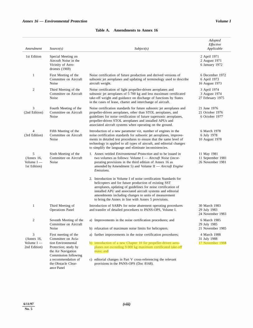
Table A. Amendments to Annex 16
Amendment Source(s) Subject(s)
AdoptedEffective
Applicable
1st Edition Special Meeting on Aircraft Noise in the Vicinity of Aero-dromes (1969)
2 April 19712 August 19716 January 1972
1 First Meeting of the Committee on Aircraft Noise
Noise certification of future production and derived versions of subsonic jet aeroplanes and updating of terminology used to describe aircraft weight.
6 December 19726 April 1973
16 August 1973
2 Third Meeting of the Committee on Aircraft Noise
Noise certification of light propeller-driven aeroplanes and subsonic jet aeroplanes of 5 700 kg and less maximum certificated take-off weight and guidance on discharge of functions by States in the cases of lease, charter and interchange of aircraft.
3 April 19743 August 1974
27 February 1975
3(2nd Edition)
Fourth Meeting of the Committee on Aircraft Noise
Noise certification standards for future subsonic jet aeroplanes and propeller-driven aeroplanes, other than STOL aeroplanes, and guidelines for noise certification of future supersonic aeroplanes, propeller-driven STOL aeroplanes and installed APUs and associated aircraft systems when operating on the ground.
21 June 197621 October 19766 October 1977
4(3rd Edition)
Fifth Meeting of the Committee on Aircraft Noise
Introduction of a new parameter viz, number of engines in the noise certification standards for subsonic jet aeroplanes, improve-ments in detailed test procedures to ensure that the same level of technology is applied to all types of aircraft, and editorial changes to simplify the language and eliminate inconsistencies.
6 March 19786 July 1978
10 August 1978
5(Annex 16, Volume I — 1st Edition)
Sixth Meeting of the Committee on Aircraft Noise
1. Annex retitled Environmental Protection and to be issued in two volumes as follows: Volume I — Aircraft Noise (incor-porating provisions in the third edition of Annex 16 as amended by Amendment 5) and Volume II — Aircraft Engine Emissions.
2. Introduction in Volume I of noise certification Standards for helicopters and for future production of existing SST aeroplanes, updating of guidelines for noise certification of installed APU and associated aircraft systems and editorial amendments including changes to units of measurement to bring the Annex in line with Annex 5 provisions.
11 May 198111 September 198126 November 1981
1 Third Meeting of Operations Panel
Introduction of SARPs for noise abatement operating procedures and transfer of detailed procedures to PANS-OPS, Volume I.
30 March 198329 July 198324 November 1983
2 Seventh Meeting of the Committee on Aircraft Noise
a) Improvements in the noise certification procedures; and
b) relaxation of maximum noise limits for helicopters.
6 March 198529 July 198521 November 1985
3(Annex 16,Volume I — 2nd Edition)
First meeting of the Committee on Avia-tion Environmental Protection; study by the Air Navigation Commission following a recommendation of the Obstacle Clear-ance Panel
a) further improvements in the noise certification procedures;
b) introduction of a new Chapter 10 for propeller-driven aero-planes not exceeding 9 000 kg maximum certificated take-off mass; and
c) editorial changes in Part V cross-referencing the relevant provisions in the PANS-OPS (Doc 8168).
4 March 198831 July 198817 November 1988
11/11/93 (viii)6/11/97
No. 5
Foreword Annex 16 — Environmental Protection
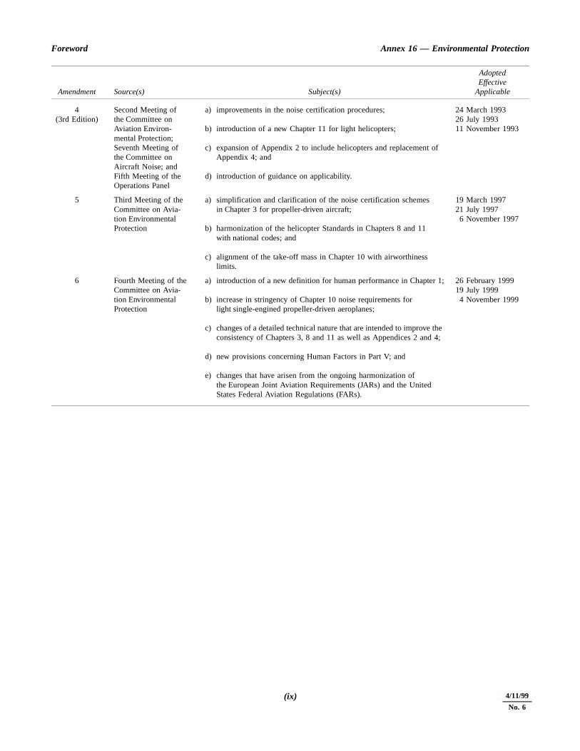
4(3rd Edition)
Second Meeting of the Committee on Aviation Environ-mental Protection; Seventh Meeting of the Committee on Aircraft Noise; and Fifth Meeting of the Operations Panel
a) improvements in the noise certification procedures;
b) introduction of a new Chapter 11 for light helicopters;
c) expansion of Appendix 2 to include helicopters and replacement of Appendix 4; and
d) introduction of guidance on applicability.
24 March 199326 July 199311 November 1993
5 Third Meeting of the Committee on Avia-tion Environmental Protection
a) simplification and clarification of the noise certification schemes in Chapter 3 for propeller-driven aircraft;
b) harmonization of the helicopter Standards in Chapters 8 and 11 with national codes; and
c) alignment of the take-off mass in Chapter 10 with airworthiness limits.
19 March 199721 July 19976 November 1997
6 Fourth Meeting of theCommittee on Avia-tion EnvironmentalProtection
a) introduction of a new definition for human performance in Chapter 1;
b) increase in stringency of Chapter 10 noise requirements for light single-engined propeller-driven aeroplanes;
c) changes of a detailed technical nature that are intended to improve the consistency of Chapters 3, 8 and 11 as well as Appendices 2 and 4;
d) new provisions concerning Human Factors in Part V; and
e) changes that have arisen from the ongoing harmonization of the European Joint Aviation Requirements (JARs) and the United States Federal Aviation Regulations (FARs).
26 February 199919 July 19994 November 1999
Amendment Source(s) Subject(s)
AdoptedEffective
Applicable
(ix) 11/11/934/11/99
No. 6

ANNEX 16 — VOLUME I 1 7/11/96
INTERNATIONAL STANDARDSAND RECOMMENDED PRACTICES
PART I. DEFINITIONS
Aeroplane. A power-driven heavier-than-air aircraft, derivingits lift in flight chiefly from aerodynamic reactions onsurfaces which remain fixed under given conditions of flight.
Aircraft. Any machine that can derive support in the atmos-phere from the reactions of the air other than the reactionsof the air against the earth’s surface.
Associated aircraft systems. Those aircraft systems drawingelectrical/pneumatic power from an auxiliary power unitduring ground operations.
Auxiliary power-unit (APU). A self-contained power-unit onan aircraft providing electrical/pneumatic power to aircraftsystems during ground operations.
By-pass ratio. The ratio of the air mass flow through theby-pass ducts of a gas turbine engine to the air mass flowthrough the combustion chambers calculated at maximumthrust when the engine is stationary in an internationalstandard atmosphere at sea level.
Derived version of an aircraft. An aircraft which, from thepoint of view of airworthiness, is similar to the noisecertificated prototype but incorporates changes in typedesign which may affect its noise characteristics adversely.
Note 1.— Where the certificating authority finds that theproposed change in design, configuration, power or mass is
so extensive that a substantially new investigation ofcompliance with the applicable airworthiness regulations isrequired, the aircraft should be considered to be a new typedesign rather than a derived version.
Note 2.— “Adversely” refers to an increase by more than0.3 dB to any one of the noise certification levels.
External equipment (helicopter). Any instrument, mechanism,part, apparatus, appurtenance, or accessory that is attachedto or extends from the helicopter exterior but is not used noris intended to be used for operating or controlling ahelicopter in flight and is not part of an airframe orengine.
Helicopter. A heavier-than-air aircraft supported in flightchiefly by the reactions of the air on one or more power-driven rotors on substantially vertical axes.
Self-sustaining powered sailplane. A powered aeroplane withavailable engine power which allows it to maintain level flightbut not to take off under its own power.
Subsonic aeroplane. An aeroplane incapable of sustaininglevel flight at speeds exceeding flight Mach number of 1.
4/11/99
No. 6

11/11/93 2 ANNEX 16 — VOLUME I
PART II. AIRCRAFT NOISE CERTIFICATION
CHAPTER 1. ADMINISTRATION
1.1 The provisions of 1.2 to 1.5 shall apply to all aircraftincluded in the classifications defined for noise certificationpurposes in Chapters 2, 3, 4, 5, 6, 8, 10 and 11 of this Partwhere such aircraft are engaged in international air navigation.
1.2 Noise certification shall be granted or validated by theState of Registry of an aircraft on the basis of satisfactoryevidence that the aircraft complies with requirements whichare at least equal to the applicable Standards specified in thisAnnex.
Note.— The documents attesting noise certification maytake the form of a separate Noise Certificate or a suitablestatement contained in another document approved by theState of Registry and required by that State to be carried in theaircraft.
1.3 The documents attesting noise certification for anaircraft shall provide at least the following information:
a) State of Registry; nationality and registration marks;
b) manufacturer’s serial number;
c) manufacturer’s type and model designation; enginetype/model; propeller type/model (if applicable);
d) statement of any additional modifications incorporatedfor the purpose of compliance with the applicable noisecertification Standards;
e) the maximum mass at which compliance with theapplicable noise certification Standards has beendemonstrated;
f) for aeroplanes for which application for certification ofthe prototype is submitted on or after 6 October 1977,and for helicopters for which application for certificationof the prototype is submitted on or after 1 January 1985:
the average noise level(s) at the reference point(s) forwhich compliance with the applicable Standard has been
demonstrated to the satisfaction of the certificatingauthority;
g) the chapter of Annex 16, Volume I, according to whichthe aircraft was certificated.
1.4 The information required under 1.3 b) through g) shallbe included in the flight manual.
1.5 Contracting States shall recognize as valid a noisecertification granted by another Contracting State providedthat the requirements under which such certification wasgranted are at least equal to the applicable Standards specifiedin this Annex.
1.6 A Contracting State shall suspend or revoke the noisecertification of an aircraft on its Register if the aircraft ceasesto comply with the applicable noise Standards. The State ofRegistry shall not remove the suspension of a noisecertification or grant a new noise certification unless theaircraft is found, on reassessment, to comply with theapplicable noise Standards.
1.7 Unless otherwise specified in this Volume of theAnnex and subject to the provisions in 1.8, the date to be usedby Contracting States in determining the applicability of theStandards in this Annex shall be the date on which either theapplication for the certificate of airworthiness for the prototypewas accepted or another equivalent prescribed procedure wascarried out by the certificating authority.
1.8 When the time interval between the acceptance of theapplication for and the issue of the certificate of airworthinessfor the prototype or, where this procedure is not used, the issueof the certificate of airworthiness for the first individualaircraft of the type, exceeds 5 years, the date to be used by thecertificating authority in determining the applicability of theappropriate Standards in this Annex shall be 5 years before thedate of issue of the certificate of airworthiness for theprototype or, where this procedure is not used, the issue of thecertificate of airworthiness for the first individual aircraft ofthe type, except in special cases when the certificatingauthority accepts an extension of this period beyond 5 years.

ors a
of
y,hnm
esithed
ts:dg
ofB
ofeerg,
ion
esithed
CHAPTER 2. SUBSONIC JET AEROPLANES — APPLICATION FORCERTIFICATE OF AIRWORTHINESS FOR THE PROTOTYPE ACCEPTED
BEFORE 6 OCTOBER 1977
2.1 Applicability
Note.— See also Chapter 1, 1.6.
2.1.1 The Standards of this chapter shall be applicable toall subsonic jet aeroplanes for which either the application forcertificate of airworthiness for the prototype was accepted oranother equivalent prescribed procedure was carried out by thecertificating authority before 6 October 1977, except thoseaeroplanes:
a) requiring a runway length* of 610 m or less atmaximum certificated mass for airworthiness; or
b) powered by engines with a by-pass ratio of 2 or moreand for which a certificate of airworthiness forthe individual aeroplane was first issued before1 March 1972; or
c) powered by engines with a by-pass ratio of less than 2,and for which either the application for certificate ofairworthiness for the prototype was accepted or anotherequivalent prescribed procedure was carried out by thecertificating authority, before 1 January 1969, and forwhich a certificate of airworthiness for the individualaeroplane was first issued before 1 January 1976.
2.1.2 The Standards of this chapter shall also beapplicable to derived versions of all aeroplanes covered by2.1.1 above for which the application for certification of achange in type design was accepted, or another equivalentprocedure was carried out by the certificating authority on orafter 26 November 1981.
2.2 Noise evaluation measure
2.2.1 The noise evaluation measure shall be the effectiveperceived noise level in EPNdB as described in Appendix 1.
2.3 Noise measurement points
2.3.1 An aeroplane, when tested in accordance with theflight test procedures of 2.6, shall not exceed the noise levelsspecified in 2.4 at the following points:
a) lateral noise measurement point: the point on a lineparallel to and 650 m from the runway centre line, extended runway centre line, where the noise level imaximum during take-off;
b) flyover noise measurement point: the point on theextended centre line of the runway and at a distance6.5 km from the start of roll;
c) approach noise measurement point: the point on theground, on the extended centre line of the runwa120 m (395 ft) vertically below the 3° descent patoriginating from a point 300 m beyond the threshold. Olevel ground this corresponds to a position 2 000 m frothe threshold.
2.4 Maximum noise levels
2.4.1 The maximum noise levels of those aeroplancovered by 2.1.1 above, when determined in accordance wthe noise evaluation method of Appendix 1, shall not excethe following:
a) at lateral and approach noise measurement poin108 EPNdB for aeroplanes with maximum certificatetake-off mass of 272 000 kg or over, decreasinlinearly with the logarithm of the mass at the rate 2 EPNdB per halving of the mass down to 102 EPNdat 34 000 kg, after which the limit remains constant;
b) at flyover noise measurement point: 108 EPNdB foraeroplanes with maximum certificated take-off mass 272 000 kg or over, decreasing linearly with thlogarithm of the mass at the rate of 5 EPNdB phalving of the mass down to 93 EPNdB at 34 000 kafter which the limit remains constant.
Note.— See Attachment A for equations for the calculatof noise levels as a function of take-off mass.
2.4.2 The maximum noise levels of those aeroplancovered by 2.1.2 above, when determined in accordance wthe noise evaluation method of Appendix 1, shall not excethe following:
* With no stopway or clearway.
ANNEX 16 — VOLUME I 3 11/11/93
Annex 16 — Environmental Protection Volume I
oried9,an
han
ons
emfter a
be
heiseear
a
ed
ing
ith
nt
aft
the
2.4.2.1 At lateral noise measurement point
106 EPNdB for aeroplanes with maximum certificated take-offmass of 400 000 kg or over, decreasing linearly with thelogarithm of the mass down to 97 EPNdB at 35 000 kg, afterwhich the limit remains constant.
2.4.2.2 At flyover noise measurement point
a) Aeroplanes with two engines or less
104 EPNdB for aeroplanes with maximum certificatedtake-off mass of 325 000 kg or over, decreasing linearlywith the logarithm of the mass at the rate of 4 EPNdBper halving of mass down to 93 EPNdB, after which thelimit remains constant.
b) Aeroplanes with three engines
As a) but with 107 EPNdB for aeroplanes withmaximum certificated take-off mass of 325 000 kg orover
or
as defined by 2.4.1 b), whichever is the lower.
c) Aeroplanes with four engines or more
As a) but with 108 EPNdB for aeroplanes withmaximum certificated take-off mass of 325 000 kg orover
or
as defined by 2.4.1 b), whichever is the lower.
2.4.2.3 At approach noise measurement point
108 EPNdB for aeroplanes with maximum certificated take-offmass of 280 000 kg or over, decreasing linearly with thelogarithm of the mass down to 101 EPNdB at 35 000 kg, afterwhich the limit remains constant.
Note.— See Attachment A for equations for the calculationof noise levels as a function of take-off mass.
2.5 Trade-offs
2.5.1 If the maximum noise levels are exceeded at one ortwo measurement points:
a) the sum of excesses shall not be greater than 4EPNdB, except that in respect of four-engined aero-planes powered by engines with by-pass ratio of 2 ormore and for which the application for certificate of
airworthiness for the prototype was accepted another equivalent prescribed procedure was carrout by the certificating authority before 1 December 196the sum of any excesses shall not be greater th5 EPNdB;
b) any excess at any single point shall not be greater t3 EPNdB; and
c) any excesses shall be offset by corresponding reductiat the other point or points.
2.6 Test procedures
2.6.1 Take-off test procedure
2.6.1.1 Average take-off thrust* shall be used from thstart of take-off to the point at which a height of at least 210(690 ft) above the runway is reached and the thrust thereashall not be reduced below that thrust which will maintainclimb gradient of at least 4 per cent.
2.6.1.2 A speed of at least V2 + 19 km/h (V2 + 10 kt)shall be attained as soon as practicable after lift-off and maintained throughout the take-off noise certification test.
2.6.1.3 A constant take-off configuration selected by tapplicant shall be maintained throughout the take-off nocertification demonstration test except that the landing gmay be retracted.
2.6.2 Approach test procedure
2.6.2.1 The aeroplane shall be stabilized and following3° ±0.5° glide path.
2.6.2.2 The approach shall be made at a stabilizairspeed of not less than 1.3 VS + 19 km/h (1.3 VS + 10 kt)with thrust stabilized during approach and over the measurpoint and continued to a normal touchdown.
2.6.2.3 The configuration of the aeroplane shall be wmaximum allowable landing flap setting.
Note.— Guidance material on the use of equivaleprocedures is provided in the Environmental Technical Manualon the use of Procedures in the Noise Certification of Aircr(Doc 9501).
* Take-off thrust representative of the mean characteristics of production engine.
11/11/93 4
r
in 1)
thein
ithd in
eeg
CHAPTER 3. 1.— SUBSONIC JET AEROPLANES —Application for Certificate of Airworthinessfor the Prototype accepted on or after6 October 1977
2.— PROPELLER-DRIVEN AEROPLANES OVER 5 700 kg —Application for Certificate of Airworthinessfor the Prototype accepted on or after1 January 1985 and before 17 November 1988
3.— PROPELLER-DRIVEN AEROPLANES OVER 8 618 kg —Application for Certificate of Airworthinessfor the Prototype accepted on or after17 November 1988
3.1 Applicability
Note 1.— See also Chapter 1, 1.6.
Note 2.— See Attachment E for guidance on interpreta-tion of these applicability provisions.
3.1.1 The Standards of this chapter shall be applicableto:
a) all subsonic jet aeroplanes, including their derivedversions, other than aeroplanes which require arunway* length of 610 m or less at maximum certifi-cated mass for airworthiness, in respect of which eitherthe application for certificate of airworthiness for theprototype was accepted or another equivalentprescribed procedure was carried out by the certifi-cating authority, on or after 6 October 1977;
b) all propeller-driven aeroplanes, including their derivedversions, of over 5 700 kg maximum certificatedtake-off mass (except those described in 6.1.1), forwhich either the application for certificate ofairworthiness for the prototype was accepted or anotherequivalent prescribed procedure was carried out by thecertificating authority, on or after 1 January 1985 andbefore 17 November 1988, except where the Standardsof Chapter 10 apply;
c) all propeller-driven aeroplanes, including their derivedversions, of over 8 618 kg maximum certificated take-off mass, for which either the application for certi-ficate of airworthiness for the prototype was acceptedor another equivalent prescribed procedure was
carried out by the certificating authority, on or afte17 November 1988.
3.1.2 Until 19 March 2002, for aeroplanes specified 3.1.1 b) and c) the requirement for lateral noise in 3.3.1 a)shall alternatively be permitted.
3.2 Noise measurements
3.2.1 Noise evaluation measure
3.2.1.1 The noise evaluation measure shall be effective perceived noise level in EPNdB as described Appendix 2.
3.3 Reference noisemeasurement points
3.3.1 An aeroplane, when tested in accordance wthese Standards, shall not exceed the noise levels specifie3.4 at the following points:
a) lateral full-power reference noise measurement point
1) for jet-powered aeroplanes: the point on a linparallel to and 450 m from the runway centrline, where the noise level is a maximum durintake-off;
* With no stopway or clearway.
ANNEX 16 — VOLUME I 5 6/11/97
No. 5
Annex 16 — Environmental Protection Volume I
disingatto
hg
hg
offofm
the
ion
istheverum
or
dB;
han
ons
2) for propeller-driven aeroplanes: the point on theextended centre line of the runway 650 mvertically below the climb-out flight path at fulltake-off power, as defined in 3.6.2;
Note.— The full-power measurement point under theflight path is an alternative for the lateral measurementpoint for propeller-driven aeroplanes.
b) flyover reference noise measurement point: the point onthe extended centre line of the runway and at a distanceof 6.5 km from the start of roll;
c) approach reference noise measurement point: the pointon the ground, on the extended centre line of the runway2 000 m from the threshold. On level ground thiscorresponds to a position 120 m (394 ft) vertically belowthe 3° descent path originating from a point 300 mbeyond the threshold.
3.3.2 Test noise measurement points
3.3.2.1 If the test noise measurement points are notlocated at the reference noise measurement points, anycorrections for the difference in position shall be made in thesame manner as the corrections for the differences betweentest and reference flight paths.
3.3.2.2 Sufficient lateral test noise measurement pointsshall be used to demonstrate to the certificating authority thatthe maximum noise level on the appropriate lateral line hasbeen clearly determined. For jet-powered aeroplanes simul-taneous measurements shall be made at one test noisemeasurement point at a symmetrical position on the other sideof the runway. In the case of propeller-driven aeroplanes,because of their inherent asymmetry in lateral noise, simul-taneous measurements shall be made at each and every testnoise measurement point at a symmetrical position (within±10 m parallel with the axis of the runway) on the oppositeside of the runway.
3.4 Maximum noise levels
3.4.1 The maximum noise levels, when determined inaccordance with the noise evaluation method of Appendix 2,shall not exceed the following:
3.4.1.1 At the lateral full-power3.4.1.1 reference noise measurement point
103 EPNdB for aeroplanes with maximum certificated take-off mass, at which the noise certification is requested, of400 000 kg and over and decreasing linearly with the logar-ithm of the mass down to 94 EPNdB at 35 000 kg, afterwhich the limit remains constant.
3.4.1.2 At flyover reference3.4.1.2 noise measurement point
a) Aeroplanes with two engines or less
101 EPNdB for aeroplanes with maximum certificatetake-off mass, at which the noise certification requested, of 385 000 kg and over and decreaslinearly with the logarithm of the aeroplane mass the rate of 4 EPNdB per halving of mass down 89 EPNdB, after which the limit is constant.
b) Aeroplanes with three engines
As a) but with 104 EPNdB for aeroplanes witmaximum certificated take-off mass of 385 000 kand over.
c) Aeroplanes with four engines or more
As a) but with 106 EPNdB for aeroplanes witmaximum certificated take-off mass of 385 000 kand over.
3.4.1.3 At approach reference3.4.1.3 noise measurement point
105 EPNdB for aeroplanes with maximum certificated take-mass, at which the noise certification is requested, 280 000 kg or over, and decreasing linearly with the logarithof the mass down to 98 EPNdB at 35 000 kg, after which limit remains constant.
Note.— See Attachment A for equations for the calculatof noise levels as a function of take-off mass.
3.4.2 If a reference ambient air temperature of 15°Cused (see 3.6.1.5. b)), 1 EPNdB shall be added to measured (and adjusted) noise level obtained at the flyomeasurement point before it is compared with the maximnoise level of 3.4.1.2.
3.5 Trade-offs
3.5.1 If the maximum noise levels are exceeded at onetwo measurement points:
a) the sum of excesses shall not be greater than 3 EPN
b) any excess at any single point shall not be greater t2 EPNdB; and
c) any excesses shall be offset by corresponding reductiat the other point or points.
64/11/99
No. 6
Part II — Chapter 3 Annex 16 — Environmental Protection
m
ustto
ht
redt
offal
ftere
heff beingitytises
ll bee
f allen
herdleis
um-
ce
3.6 Noise certificationreference procedures
3.6.1 General conditions
3.6.1.1 The reference procedures shall comply with theappropriate airworthiness requirements.
3.6.1.2 The calculations of reference procedures andflight paths shall be approved by the certificating authority.
3.6.1.3 Except in conditions specified in 3.6.1.4, thetake-off and approach reference procedures shall be thosedefined in 3.6.2 and 3.6.3 respectively.
3.6.1.4 When it is shown by the applicant that the designcharacteristics of the aeroplane would prevent flight beingconducted in accordance with 3.6.2 and 3.6.3, the referenceprocedures shall:
a) depart from the reference procedures defined in 3.6.2and 3.6.3 only to the extent demanded by those designcharacteristics which make compliance with theprocedures impossible; and
b) be approved by the certificating authority.
3.6.1.5 The reference procedures shall be calculatedunder the following reference atmospheric conditions:
a) sea level atmospheric pressure of 1 013.25 hPa;
b) ambient air temperature of 25°C, i.e. ISA + 10°Cexcept that, at the discretion of the certificatingauthority, an alternative reference ambient airtemperature of 15°C, i.e. ISA may be used;
c) relative humidity of 70 per cent; and
d) zero wind.
Note.— The reference atmosphere in terms of temperatureand relative humidity is homogeneous when used for thecalculation of atmospheric absorption coefficients.
3.6.2 Take-off reference procedure
3.6.2.1 Take-off reference flight path shall be calculatedas follows:
a) average engine take-off thrust or power shall be usedfrom the start of take-off to the point where at least thefollowing height above runway level is reached:
— aeroplanes with two engines or less — 300 m(984 ft)
— aeroplanes with three engines — 260 m (853 ft)
— aeroplanes with four engines or more — 210 (689 ft);
b) upon reaching the height specified in a) above, the thror power shall not be reduced below that required maintain:
1) a climb gradient of 4 per cent; and
2) in the case of multi-engined aeroplanes, level fligwith one engine inoperative;
whichever thrust or power is greater;
c) for the purpose of determining the lateral full-powenoise level, the reference flight path shall be calculaton the basis of using full take-off power throughouwithout a thrust or power reduction;
d) the speed shall be the all-engines operating take-climb speed selected by the applicant for use in normoperation, which shall be at least V2 + 19 km/h (V2 +10 kt) but not greater than V2 + 37 km/h (V2 + 20 kt)and which shall be attained as soon as practicable alift-off and be maintained throughout the take-off noiscertification test;
e) a constant take-off configuration selected by tapplicant shall be maintained throughout the take-oreference procedure except that the landing gear mayretracted. Configuration shall be interpreted as meanthe conditions of the systems and centre of gravposition and shall include the position of lifaugmentation devices used, whether the APU operating, and whether air bleeds and power off-takare operating;
f) the mass of the aeroplane at the brake release shathe maximum take-off mass at which the noiscertification is requested; and
g) the average engine shall be defined by the average othe certification compliant engines used during thaeroplane flight tests up to and during certification wheoperated to the limitations and procedures given in tflight manual. This will establish a technical standaincluding the relationship of thrust/power to controparameters (e.g. N1 or EPR). Noise measurements madduring certification tests shall be corrected to thstandard.
Note.— Take-off thrust/power used shall be the maximavailable for normal operations as scheduled in the performance section of the aeroplane flight manual for the referenatmospheric conditions given in 3.6.1.5.
7 4/11/99
No. 6

Annex 16 — Environmental Protection Volume I
ivedin
ds inade
ees-e-
theonstorht
hallgle
ed allres
nts-offorenge
ce-
ft
heaneeed bytheage/h
yric
for
3.6.3 Approach reference procedure
3.6.3.1 The approach reference flight path shall becalculated as follows:
a) the aeroplane shall be stabilized and following a 3°glide path;
b) the approach shall be made at a stabilized airspeed ofnot less than the minimum value of VREF + 19 km/h(minimum VREF + 10 kt) with thrust or power stabilizedduring approach and over the measuring point, andcontinued to a normal touchdown;
Note.— The minimum value of VREF is defined as 1.3VS or the approximate equivalent of 1.23 VS1G .
c) the constant approach configuration as used in theairworthiness certification tests, but with the landinggear down, shall be maintained throughout the approachreference procedure;
d) the mass of the aeroplane at the touchdown shall be themaximum landing mass permitted in the approachconfiguration defined in 3.6.3.1 c) at which noisecertification is requested; and
e) the most critical (that which produces the highestnoise level) configuration with normal deployment ofaerodynamic control surfaces including lift and dragproducing devices, at the mass at which certification isrequested shall be used. This configuration includes allthose items listed in 5.2.5 of Appendix 2 that willcontribute to the noisiest continuous state at themaximum landing mass in normal operation.
3.7 Test procedures
3.7.1 The test procedures shall be acceptable to theairworthiness and noise certificating authority of the Stateissuing the certificate.
3.7.2 The test procedures and noise measurements shallbe conducted and processed in an approved manner to yield
the noise evaluation measure designated as effective percenoise level, EPNL, in units of EPNdB, as described Appendix 2.
3.7.3 Acoustic data shall be adjusted by the methooutlined in Appendix 2 to the reference conditions specifiedthis Chapter. Adjustments for speed and thrust shall be mas described in Section 9 of Appendix 2.
3.7.4 If the mass during the test is different from thmass at which the noise certification is requested, the necsary EPNL adjustment shall not exceed 2 EPNdB for takoffs and 1 EPNdB for approaches. Data approved by certificating authority shall be used to determine the variatiof EPNL with mass for both take-off and approach teconditions. Similarly the necessary EPNL adjustment fvariations in approach flight path from the reference fligpath shall not exceed 2 EPNdB.
3.7.5 For the approach conditions the test procedures sbe accepted if the aeroplane follows a steady glide path anof 3° ±0.5°.
3.7.6 If equivalent test procedures different from threference procedures are used, the test procedures anmethods for adjusting the results to the reference procedushall be approved by the certificating authority. The amouof the adjustments shall not exceed 16 EPNdB on takeand 8 EPNdB on approach, and if the adjustments are mthan 8 EPNdB and 4 EPNdB respectively, the resultinumbers shall not be within 2 EPNdB of the limit noislevels specified in 3.4.
Note.— Guidance material on the use of equivalent produres is provided in the Environmental Technical Manual onthe use of Procedures in the Noise Certification of Aircra(Doc 9501).
3.7.7 For take-off, lateral, and approach conditions, tvariation in instantaneous indicated airspeed of the aeroplmust be maintained within ±3 per cent of the average airspbetween the 10 dB-down points. This shall be determinedreference to the pilot’s airspeed indicator. However, when instantaneous indicated airspeed varies from the averairspeed over the 10 dB-down points by more than ±5.5 km(±3 kt), and this is judged by the certificating authoritrepresentative on the flight deck to be due to atmospheturbulence, then the flight so affected shall be rejected noise certification purposes.
84/11/99
No. 6

ANNEX 16 — VOLUME I 9 11/11/93
CHAPTER 4. SUPERSONIC AEROPLANES
4.1 Supersonic aeroplanes — application forcertificate of airworthiness for the prototype
accepted before 1 January 1975
4.1.1 The Standards of Chapter 2 of this Part, with theexception of maximum noise levels specified in 2.4, shall beapplicable to all supersonic aeroplanes, including their derivedversions, in respect of which either the application for thecertificate of airworthiness for the prototype was accepted oranother equivalent prescribed procedure was carried out by thecertificating authority before 1 January 1975 and for which acertificate of airworthiness for the individual aeroplane wasfirst issued after 26 November 1981.
4.1.2 The maximum noise levels of those aeroplanescovered by 4.1.1, when determined in accordance with thenoise evaluation method of Appendix 1, shall not exceed the
measured noise levels of the first certificated aeroplane of thetype.
4.2 Supersonic aeroplanes — application forcertificate of airworthiness for the prototype
accepted on or after 1 January 1975
Note.— Standards and Recommended Practices for theseaeroplanes are not yet developed but the noise levels ofChapter 3 of this Part applicable to subsonic jet aeroplanesmay be used as guidelines for aeroplanes for which the appli-cation for a certificate of airworthiness for the prototype wasaccepted or another equivalent prescribed procedure wascarried out by the certificating authority on or after1 January 1975.

t by
ghrees
thein
ese4 at
el is
nce
ayiswm
notanyheeen
CHAPTER 5. PROPELLER-DRIVEN AEROPLANES OVER 5 700 kg —APPLICATION FOR CERTIFICATE OF AIRWORTHINESS FOR THE PROTOTYPE
ACCEPTED BEFORE 1 JANUARY 1985
5.1 Applicability
Note 1.— See also Chapter 1, 1.6.
Note 2.— See Attachment E for guidance on interpreta-tion of these applicability provisions.
5.1.1 The Standards defined hereunder are not applicableto:
a) aeroplanes requiring a runway* length of 610 m or lessat maximum certificated mass for airworthiness;
b) aeroplanes specifically designed for fire fighting;
c) aeroplanes specifically designed for agriculturalpurposes;
d) aeroplanes to which the Standards of Chapter 6 apply;and
e) aeroplanes to which the Standards of Chapter 10 apply.
5.1.2 The Standards of this chapter shall be applicable toall propeller-driven aeroplanes, including their derivedversions, of over 5 700 kg maximum certificated take-offmass for which either the application for a certificate ofairworthiness for the prototype was accepted or anotherequivalent prescribed procedure was carried out by thecertificating authority on or after 6 October 1977 and before1 January 1985.
5.1.3 The Standards of Chapter 2, with the exception ofSections 2.1 and 2.4.2, shall be applicable to derived versionsand individual aeroplanes of over 5 700 kg maximum certifi-cated take-off mass and to which Standards of Chapter 6 donot apply and are of the type for which application for acertificate of airworthiness for the prototype was accepted oranother equivalent prescribed procedure was carried out bythe certificating authority before 6 October 1977 and forwhich a certificate of airworthiness for the individualaeroplane was issued on or after 26 November 1981.
5.1.4 The Standards of Chapter 3, with the exception ofSection 3.1 shall be applicable to all propeller-driven aero-planes, including their derived versions, of over 5 700 kgmaximum take-off mass, for which either the application fora certificate of airworthiness for the prototype was accepted,
or another equivalent prescribed procedure was carried outhe certificating authority on or after 1 January 1985.
Note.— The Standards in Chapters 2 and 3 althoudeveloped previously for subsonic jet aeroplanes aconsidered suitable for application to other aeroplane typregardless of the type of power installed.
5.2 Noise measurements
5.2.1 Noise evaluation measure
5.2.1.1 The noise evaluation measure shall be effective perceived noise level in EPNdB as described Appendix 2.
5.3 Reference noise measurement points
5.3.1 An aeroplane, when tested in accordance with thStandards, shall not exceed the noise levels specified in 5.the following points:
a) lateral reference noise measurement point: the point ona line parallel to and 450 m from the runway centre linor extended runway centre line, where the noise levea maximum during take-off;
b) flyover reference noise measurement point: the point onthe extended centre line of the runway and at a distaof 6.5 km from the start of roll;
c) approach reference noise measurement point: the pointon the ground, on the extended centre line of the runw2 000 m from the threshold. On level ground thcorresponds to a position 120 m (395 ft) vertically belothe 3° descent path originating from a point 300 beyond the threshold.
5.3.2 Test noise measurement points
5.3.2.1 If the test noise measurement points are located at the reference noise measurement points, corrections for the difference in position shall be made in tsame manner as the corrections for the differences betwtest and reference flight paths.
* With no stopway or clearway.
11/11/93 10 ANNEX 16 — VOLUME I
Part II — Chapter 5 Annex 16 — Environmental Protection
ons
he
nd
eose
ignngnce
6.2igne
ted
Cgir
as
ofveff
orcer-
5.3.2.2 Sufficient lateral test noise measurement pointsshall be used to demonstrate to the certificating authority thatthe maximum noise level on the appropriate lateral line hasbeen clearly determined. Simultaneous measurements shall bemade at one test noise measurement point at a symmetricalposition on the other side of the runway.
5.3.2.3 The applicant shall demonstrate to the certificatingauthority that during flight test, lateral and flyover noise levelswere not separately optimized at the expense of each other.
5.4 Maximum noise levels
5.4.1 The maximum noise levels, when determined inaccordance with the noise evaluation method of Appendix 2,shall not exceed the following:
a) at lateral reference noise measurement point:96 EPNdB constant limit for aeroplanes with maxi-mum take-off mass, at which the noise certification isrequested, up to 34 000 kg and increasing linearlywith the logarithm of aeroplane mass at the rate of2 EPNdB per doubling of mass from that point until thelimit of 103 EPNdB is reached, after which the limit isconstant;
b) at flyover reference noise measurement point:89 EPNdB constant limit for aeroplanes with maxi-mum take-off mass, at which the noise certification isrequested, up to 34 000 kg and increasing linearly withthe logarithm of aeroplane mass at the rate of 5 EPNdBper doubling of mass from that point until the limit of106 EPNdB is reached, after which the limit is constant;and
c) at approach reference noise measurement point:98 EPNdB constant limit for aeroplanes with maxi-mum take-off mass, at which the noise certification isrequested, up to 34 000 kg and increasing linearlywith the logarithm of aeroplane mass at the rate of2 EPNdB per doubling of mass from that point until thelimit of 105 EPNdB is reached, after which the limit isconstant.
Note.— See Attachment A for equations for thecalculation of noise levels as a function of take-off mass.
5.5 Trade-offs
5.5.1 If the maximum noise levels are exceeded at one ortwo measurement points:
a) the sum of excesses shall not be greater than3 EPNdB;
b) any excess at any single point shall not be greaterthan 2 EPNdB; and
c) any excesses shall be offset by corresponding reductiat the other point or points.
5.6 Noise certificationreference procedures
5.6.1 General conditions
5.6.1.1 The reference procedures shall comply with tappropriate airworthiness requirements.
5.6.1.2 The calculations of reference procedures aflight paths shall be approved by the certificating authority.
5.6.1.3 Except in conditions specified in 5.6.1.4, thtake-off and approach reference procedures shall be thdefined in 5.6.2 and 5.6.3 respectively.
5.6.1.4 When it is shown by the applicant that the descharacteristics of the aeroplane would prevent flight beiconducted in accordance with 5.6.2 and 5.6.3, the refereprocedures shall:
a) depart from the reference procedures defined in 5.and 5.6.3 only to the extent demanded by those descharacteristics which make compliance with thprocedures impossible; and
b) be approved by the certificating authority.
5.6.1.5 The reference procedures shall be calculaunder the following reference atmospheric conditions:
a) sea level atmospheric pressure of 1 013.25 hPa;
b) ambient air temperature of 25°C, i.e. ISA + 10°except that at the discretion of the certificatinauthority, an alternative reference ambient atemperature of 15°C, i.e. ISA may be used;
c) relative humidity of 70 per cent; and
d) zero wind.
5.6.2 Take-off reference procedure
5.6.2.1 The take-off flight path shall be calculated follows:
a) average take-off power shall be used from the starttake-off to the point where at least the height aborunway level shown below is reached. The take-opower used shall be the maximum available fnormal operations as scheduled in the performansection of the aeroplane flight manual for the refeence atmospheric conditions given in 5.6.1.5.
11 11/11/93

Annex 16 — Environmental Protection Volume I
beche
iseis
thete
hallieldivedin
ds ine as
ssarynding
Ls.inot
hallgle
d allres
ntsoffore
nge
nt
of
— aeroplanes with two engines or less — 300 m(985 ft)
— aeroplanes with three engines — 260 m (855 ft)
— aeroplanes with four engines or more — 210 m(690 ft);
b) upon reaching the height specified in a) above, thepower shall not be reduced below that required tomaintain:
1) climb gradient of 4 per cent; or
2) in the case of multi-engined aeroplanes, level flightwith one engine inoperative;
whichever power is the greater;
c) the speed shall be the all-engines operating take-offclimb speed selected by the applicant for use in normaloperation, which shall be at least V2 + 19 km/h (V2 +10 kt) and which shall be attained as soon aspracticable after lift-off and be maintained throughoutthe take-off noise certification test;
d) a constant take-off configuration selected by theapplicant shall be maintained throughout the take-offreference procedure except that the landing gear may beretracted; and
e) the mass of the aeroplane at the brake-release shall bethe maximum take-off mass at which the noisecertification is requested.
5.6.3 Approach reference procedure
5.6.3.1 The approach reference flight path shall becalculated as follows:
a) the aeroplane shall be stabilized and following a 3° glidepath;
b) the approach shall be made at a stabilized airspeed ofnot less than 1.3 VS + 19 km/h (1.3 VS + 10 kt) withpower stabilized during approach and over themeasuring point, and continued to a normal touchdown;
c) the constant approach configuration used in theairworthiness certification test, but with the landing geardown, shall be maintained throughout the approachreference procedure;
d) the mass of the aeroplane at the touchdown shall the maximum landing mass permitted in the approaconfiguration defined in 5.6.3.1 c) at which noiscertification is requested; and
e) the most critical (that which produces the highest nolevels) configuration at the mass at which certification requested, shall be used.
5.7 Test procedures
5.7.1 The test procedures shall be acceptable to airworthiness and noise certificating authority of the Staissuing the certificate.
5.7.2 The test procedures and noise measurements sbe conducted and processed in an approved manner to ythe noise evaluation measure designated as effective percenoise level, EPNL, in units of EPNdB, as described Appendix 2.
5.7.3 Acoustic data shall be adjusted by the methooutlined in Appendix 2 to the reference conditions specifiedthis chapter. Adjustments for speed and thrust shall be maddescribed in Section 9 of Appendix 2.
5.7.4 If the mass during the test is different from the maat which the noise certification is requested, the necessEPNL adjustment shall not exceed 2 EPNdB for take-offs a1 EPNdB for approaches. Data approved by the certificatauthority shall be used to determine the variation of EPNwith mass for both take-off and approach test conditionSimilarly, the necessary EPNL adjustment for variations approach flight path from the reference flight path shall nexceed 2 EPNdB.
5.7.5 For the approach conditions the test procedures sbe accepted if the aeroplane follows a steady glide path anof 3° ±0.5°.
5.7.6 If equivalent test procedures different fromthe reference procedures are used, the test procedures anmethods for adjusting the results to the reference procedushall be approved by the certificating authority. The amouof the adjustments shall not exceed 16 EPNdB on take-and 8 EPNdB on approach, and if the adjustments are mthan 8 EPNdB and 4 EPNdB respectively, the resultinumbers shall not be within 2 EPNdB of the limit noislevels specified in 5.4.
Note.— Guidance material on the use of equivaleprocedures is provided in the Environmental Technical Manualon the use of Procedures in the Noise Certification Aircraft (Doc 9501).
11/11/93 12

ANNEX 16 — VOLUME I 13 7/11/96
CHAPTER 6. PROPELLER-DRIVEN AEROPLANES NOT EXCEEDING8 618 kg — APPLICATION FOR CERTIFICATE OF AIRWORTHINESS
FOR THE PROTOTYPE ACCEPTED BEFORE 17 NOVEMBER 1988
6.1 Applicability
Note 1.— See also Chapter 1, 1.6.
Note 2.— See Attachment E for guidance on interpreta-tion of these applicability provisions.
6.1.1 The Standards of this chapter shall be applicable toall propeller-driven aeroplanes, except those aeroplanesspecifically designed for aerobatic purposes or agricultural orfire fighting uses, of a maximum certificated take-off mass notexceeding 8 618 kg for which:
a) application for the certificate of airworthiness for theprototype was accepted, or another equivalent pre-scribed procedure was carried out by the certificatingauthority, on or after 1 January 1975 and before17 November 1988, except for derived versions forwhich an application for a certificate of airworthinesswas accepted or another equivalent procedure wascarried out by the certificating authority on or after17 November 1988 in which case the Standards ofChapter 10 apply; or
b) a certificate of airworthiness for the individualaeroplane was first issued on or after 1 January 1980.
6.2 Noise evaluation measure
6.2.1 The noise evaluation measure shall be a weightedover-all sound pressure level as defined in InternationalElectrotechnical Commission (IEC) Publication 179*. Theweighting applied to each sinusoidal component of the soundpressure shall be given as a function of frequency by thestandard reference curve called “A”.
6.3 Maximum noise levels
6.3.1 For aeroplanes specified in 6.1.1 a) and 6.1.1 b), themaximum noise levels when determined in accordance withthe noise evaluation method of Appendix 3 shall not exceedthe following:
— a 68 dB(A) constant limit up to an aeroplane mass of600 kg, varying linearly with mass from that point to1 500 kg, after which the limit is constant at 80 dB(A)up to 8 618 kg.
Note.— Where an aeroplane comes within the provisionsof Chapter 10, 10.1.2, the limit of 80 dB(A) applies up to8 618 kg.
6.4 Noise certificationreference procedures
6.4.1 The reference procedure shall be calculated underthe following reference atmospheric conditions:
a) sea level atomospheric pressure of 1 013.25 hPa;
b) ambient air temperature of 25°C, i.e. ISA + 10°C.
6.5 Test procedures
6.5.1 Either the test procedures described in 6.5.2 and6.5.3 or equivalent test procedures approved by thecertificating authority shall be used.
6.5.2 Tests to demonstrate compliance with the maximumnoise levels of 6.3.1 shall consist of a series of level flightsoverhead the measuring station at a height of
The aeroplane shall pass over the measuring point within ±10°from the vertical.
6.5.3 Overflight shall be performed at the highest powerin the normal operating range**, stabilized airspeed and withthe aeroplane in the cruise configuration.
Note.— Guidance material on the use of equivalentprocedures is provided in the Environmental TechnicalManual on the use of Procedures in the Noise Certification ofAircraft (Doc 9501).
* * As amended. Available from the Bureau central de la Commissionélectrotechnique internationale, 1 rue de Varembé, Geneva,Switzerland.
** This is normally indicated in the Aeroplane Flight Manual and onthe flight instruments.
300 +10 m (985 +30 ft)–30 –100
6/11/97
No. 5
11/11/93 14 ANNEX 16 — VOLUME I
CHAPTER 7. PROPELLER-DRIVEN STOL AEROPLANES
Note.— Standards and Recommended Practices for thischapter are not yet developed. In the meantime, guidelinesprovided in Attachment B may be used for noise certificationof propeller-driven STOL aeroplanes for which a certificateof airworthiness for the individual aeroplane was first issuedon or after 1 January 1976.

d
nd
));
ythd
e
d
e
ythd
e
nd
eea°
ythnde
mise
he
CHAPTER 8. HELICOPTERS
8.1 Applicability
Note.— See also Chapter 1, 1.6.
8.1.1 The Standards of this chapter shall be applicable toall helicopters, except those designed exclusively for agri-cultural, fire fighting or external load carrying purposes, forwhich:
a) application for the certificate of airworthiness for theprototype was accepted, or another equivalent prescribedprocedure was carried out by the certificating authority,on or after 1 January 1985; or
b) application for a change of type design, where suchchange affects any of the helicopter’s noise certificationlevels adversely, was accepted, or other equivalentprescribed procedure was carried out by the certificatingauthority, on or after 17 November 1988.
8.1.2 Certification of helicopters which are capable ofcarrying external loads or external equipment shall be madewithout such loads or equipment fitted.
Note 1.— Helicopters which comply with the Standardswith internal loads may be excepted when carrying externalloads or external equipment, if such operations are conductedat a gross mass or with other operating parameters which arein excess of those certificated for airworthiness with internalloads.
Note 2.— The term “adversely” is explained under thedefinition of “derived version of an aircraft” in Part I.
8.1.3 An applicant under 8.1.1 may alternatively elect toshow compliance with Chapter 11 instead of Chapter 8 if thehelicopter has a maximum certificated take-off mass of2 730 kg or less.
8.2 Noise evaluation measure
8.2.1 The noise evaluation measure shall be the effectiveperceived noise level in EPNdB as described in Appendix 2.
8.3 Reference noise measurement points
8.3.1 A helicopter, when tested in accordance with theseStandards, shall not exceed the noise levels specified in 8.4 atthe following points:
a) Take-off reference noise measurement points
1) a flight path reference point located on the grounvertically below the flight path defined in thetake-off reference procedure (see 8.6.2.1) a500 m horizontally in the direction of flight fromthe point at which transition to climbing flight isinitiated in the reference procedure (see 8.6.2.1 b
2) two other points on the ground symmetricalldisposed at 150 m on both sides of the flight padefined in the take-off reference procedure anlying on a line through the flight path referencpoint.
b) Overflight reference noise measurement points
1) A flight path reference point located on the groun150 m (490 ft) vertically below the flight pathdefined in the overflight reference procedur(see 8.6.3.1);
2) two other points on the ground symmetricalldisposed at 150 m on both sides of the flight padefined in the overflight reference procedure anlying on a line through the flight path referencpoint.
c) Approach reference noise measurement points
1) a flight path reference point located on the grou120 m (395 ft) vertically below the flight pathdefined in the approach reference procedure (s8.6.4.1). On level ground, this corresponds to position 1 140 m from the intersection of the 6.0approach path with the ground plane;
2) two other points on the ground symmetricalldisposed at 150 m on both sides of the flight padefined in the approach reference procedure alying on a line through the flight path referencpoint.
8.4 Maximum noise levels
8.4.1 For helicopters specified in 8.1.1, the maximunoise levels when determined in accordance with the noevaluation method of Appendix 2 shall not exceed tfollowing:
ANNEX 16 — VOLUME I 15 7/11/966/11/97
No. 5

Annex 16 — Environmental Protection Volume I
igng
the
.2,sehe
for
ptnC,
eest theedesttorhichllygbeed
tingorse
be
mdceisedm
erhe
8.4.1.1 At the take-off flight path reference point:109 EPNdB for helicopters with maximum certificated take-off mass at which the noise certification is requested, of80 000 kg and over and decreasing linearly with thelogarithm of the helicopter mass at a rate of 3 EPNdB perhalving of mass down to 89 EPNdB after which the limit isconstant.
8.4.1.2 At the overflight path reference point:108 EPNdB for helicopters with maximum certificated take-off mass at which the noise certification is requested, of80 000 kg and over and decreasing linearly with thelogarithm of the helicopter mass at a rate of 3 EPNdB perhalving of mass down to 88 EPNdB after which the limit isconstant.
8.4.1.3 At the approach flight path reference point:110 EPNdB for helicopters with maximum certificated take-off mass at which the noise certification is requested, of80 000 kg and over and decreasing linearly with thelogarithm of the helicopter mass at a rate of 3 EPNdB perhalving of mass down to 90 EPNdB after which the limit isconstant.
Note.— See Attachment A for equations for the calculationof noise levels as a function of take-off mass.
8.5 Trade-offs
8.5.1 If the noise level limits are exceeded at one or twomeasurement points:
a) the sum of excesses shall not be greater than 4 EPNdB;
b) any excess at any single point shall not be greater than3 EPNdB; and
c) any excess shall be offset by corresponding reductions atthe other point or points.
8.6 Noise certificationreference procedures
8.6.1 General conditions
8.6.1.1 The reference procedures shall comply with theappropriate airworthiness requirements.
8.6.1.2 The reference procedures and flight paths shall beapproved by the certificating authority.
8.6.1.3 Except in conditions specified in 8.6.1.4, thetake-off, overflight and approach reference procedures shallbe those defined in 8.6.2, 8.6.3 and 8.6.4 respectively.
8.6.1.4 When it is shown by the applicant that the descharacteristics of the helicopter would prevent flight beinconducted in accordance with 8.6.2, 8.6.3 or 8.6.4, reference procedures shall:
a) depart from the reference procedures defined in 8.68.6.3 or 8.6.4 only to the extent demanded by thodesign characteristics which make compliance with treference procedures impossible; and
b) be approved by the certificating authority.
8.6.1.5 The reference procedures shall be establishedthe following reference atmospheric conditions:
a) sea level atmospheric pressure of 1 013.25 hPa;
b) ambient air temperature of 25°C, i.e. ISA + 10°C excethat, at the discretion of the certificating authority, aalternative reference ambient air temperature of 15°i.e. ISA may be used;
c) relative humidity of 70 per cent; and
d) zero wind.
8.6.1.6 In 8.6.2.1 c), 8.6.3.1 c) and 8.6.4.1 c), thmaximum normal operating rpm shall be taken as the highrotor speed for each reference procedure corresponding toairworthiness limit imposed by the manufacturer and approvby the certificating authority. Where a tolerance on the highrotor speed is specified, the maximum normal operating rospeed shall be taken as the highest rotor speed about wthat tolerance is given. If the rotor speed is automaticalinked with flight condition, the maximum normal operatinrotor speed corresponding with that flight condition shall used during the noise certification procedure. If rotor specan be changed by pilot action, the highest normal operarotor speed specified in the flight manual limitation section fpower-on conditions shall be used during the noicertification procedure.
8.6.2 Take-off reference procedure
8.6.2.1 The take-off reference flight procedure shall established as follows:
a) the helicopter shall be stabilized at the maximutake-off power corresponding to minimum installeengine(s) specification power available for the referenambient conditions or gearbox torque limit, whichever lower, and along a path starting from a point locat500 m prior to the flight path reference point, at 20 (65 ft) above the ground;
b) the best rate of climb speed Vy, or the lowestapproved speed for the climb after take-off, whichevis the greater, shall be maintained throughout ttake-off reference procedure;
7/11/96 164/11/99
No. 6

Part II — Chapter 8 Annex 16 — Environmental Protection
0°
qual
thend a
ed
hi-ed,ce
theis
thete
hallieldivedin
elystic 2,
this
nd
f
ry.0
e bye
c) the steady climb shall be made with the rotor speedstabilized at the maximum normal operating rpm certi-ficated for take-off;
d) a constant take-off configuration selected by the appli-cant shall be maintained throughout the take-off refer-ence procedure except that the landing gear may beretracted;
e) the mass of the helicopter shall be the maximum take-off mass at which noise certification is requested; and
f) the reference take-off path is defined as a straight linesegment inclined from the starting point (500 m prior tothe centre microphone location and 20 m (65 ft) aboveground level) at an angle defined by Best Rate of Climb(BRC) and Vy for minimum specification engineperformance.
8.6.3 Overflight reference procedure
8.6.3.1 The overflight reference procedure shall beestablished as follows:
a) the helicopter shall be stabilized in level flight overheadthe flight path reference point at a height of 150 m(492 ft);
b) a speed of 0.9 VH or 0.9 VNE, or 0.45 VH + 120 km/h(0.45 VH + 65 kt) or 0.45 VNE + 120 km/h (0.45 VNE +65 kt), whichever is the least, shall be maintainedthroughout the overflight reference procedure;
Note.— For noise certification purposes, VH is definedas the airspeed in level flight obtained using the torquecorresponding to minimum engine installed, maximumcontinuous power available for sea level pressure(1 013.25 hPa), 25°C ambient conditions at the relevantmaximum certificated mass. VNE is defined as thenot-to-exceed airworthiness airspeed imposed by themanufacturer and approved by the certificating authority.
c) the overflight shall be made with the rotor speedstabilized at the maximum normal operating rpmcertificated for level flight;
d) the helicopter shall be in the cruise configuration; and
e) the mass of the helicopter shall be the maximum take-offmass at which noise certification is requested.
8.6.3.2 The value of VH and/or VNE used for noisecertification shall be quoted in the approved flight manual.
8.6.4 Approach reference procedure
8.6.4.1 The approach reference procedure shall beestablished as follows:
a) the helicopter shall be stabilized and following a 6.approach path;
b) the approach shall be made at a stabilized airspeed eto the best rate of climb speed Vy, or the lowestapproved speed for the approach, whichever is greater, with power stabilized during the approach aover the flight path reference point, and continued tonormal touchdown;
c) the approach shall be made with the rotor spestabilized at the maximum normal operating rpmcertificated for approach;
d) the constant approach configuration used in airwortness certification tests, with the landing gear extendshall be maintained throughout the approach referenprocedure; and
e) the mass of the helicopter at touchdown shall be maximum landing mass at which noise certification requested.
8.7 Test procedures
8.7.1 The test procedures shall be acceptable to airworthiness and noise certificating authority of the Staissuing the certificate.
8.7.2 The test procedures and noise measurements sbe conducted and processed in an approved manner to ythe noise evaluation measure designated as effective percenoise level, EPNL, in units of EPNdB, as described Appendix 2.
8.7.3 Test conditions and procedures shall be clossimilar to reference conditions and procedures or the acoudata shall be adjusted, by the methods outlined in Appendixto the reference conditions and procedures specified in chapter.
8.7.4 Adjustments for differences between test areference flight procedures shall not exceed:
a) for take-off 4.0 EPNdB, of which the arithmetic sum o∆1 and the term –7.5 log (QK/QrKr) from ∆2 shall notin total exceed 2.0 EPNdB;
b) for overflight or approach 2.0 EPNdB.
8.7.5 During the test the average rotor rpm shall not vafrom the normal maximum operating rpm by more than ±1per cent during the 10 dB-down time period.
8.7.6 The helicopter airspeed shall not vary from threference airspeed appropriate to the flight demonstrationmore than ±9 km/h (5 kt) throughout the 10 dB-down timperiod.
17 7/11/964/11/99
No. 6

Annex 16 — Environmental Protection Volume I
heeedach
notted per
ofted
nt
of
8.7.7 When the wind speed component in the direction offlight exceeds 9 km/h (5 kt), the number of level overflightsmade with a head wind component shall be equal to thenumber of level overflights made with a tail wind component.
8.7.8 The helicopter shall fly within ±10° or ±20 m,whichever is greater, from the vertical above the referencetrack throughout the 10 dB-down time period(see Figure 8-1).
8.7.9 The helicopter height shall not vary duringoverflight from the reference height at the overhead point bymore than ±9 m (30 ft).
8.7.10 During the approach noise demonstration thelicopter shall be established on a stabilized constant spapproach within the airspace contained between approangles of 5.5° and 6.5°.
8.7.11 Tests shall be conducted at a helicopter mass less than 90 per cent of the relevant maximum certificamass and may be conducted at a mass not exceeding 105cent of the relevant maximum certificated mass. For eachthe three flight conditions, at least one test must be compleat or above this maximum certificated mass.
Note.— Guidance material on the use of equivaleprocedures is provided in the Environmental TechnicalManual on the use of Procedures in the Noise CertificationAircraft (Doc 9501).
Figure 8-1. Helicopter lateral deviation tolerances
PN LT M – 10 PN LT M + 10PN LT M
7/11/96 184/11/99
No. 6

ANNEX 16 — VOLUME I 19 11/11/93
CHAPTER 9. INSTALLED AUXILIARY POWER UNITS (APU)AND ASSOCIATED AIRCRAFT SYSTEMS
DURING GROUND OPERATIONS
Note.— Standards and Recommended Practices for thisChapter are not yet developed. In the meantime, guidelinesprovided in Attachment C may be used for noise certificationof installed auxiliary power units (APU) and associatedaircraft systems in:
a) all aircraft for which application for a certificate ofairworthiness for the prototype was accepted oranother equivalent prescribed procedure was carriedout by the certificating authority, on or after6 October 1977; and
b) aircraft of existing type design for which application fora change of type design involving the basic APUinstallation was accepted or another equivalentprescribed procedure was carried out by the certifi-cating authority, on or after 6 October 1977.
tofe
um
ithd in
t ist a
thethe
aof
itt
aof
e
CHAPTER 10. PROPELLER-DRIVEN AEROPLANES NOTEXCEEDING 8 618 kg — APPLICATION FOR CERTIFICATE
OF AIRWORTHINESS FOR THE PROTOTYPE OR DERIVED VERSIONACCEPTED ON OR AFTER 17 NOVEMBER 1988
10.1 Applicability
Note 1.— See also Chapter 1, 1.6.
Note 2.— See Attachment E for guidance on interpretationof these applicability provisions.
10.1.1 The Standards of this chapter shall be applicable toall propeller-driven aeroplanes and their derived versions, witha certificated take-off mass not exceeding 8 618 kg, exceptthose aeroplanes specifically designed for aerobatic purposesand agricultural or fire fighting uses and self-sustainingpowered sailplanes.
10.1.2 For an aeroplane for which application for thecertificate of airworthiness for the prototype or for all derivedversions was accepted, or another equivalent prescribedprocedure was carried out by the certificating authority, on orafter 17 November 1988, except for those aeroplanes specifiedin 10.1.4, the noise limits of 10.4 a) shall apply.
10.1.3 For aeroplanes specified in 10.1.2 which fail tocomply with the Standards of this chapter and where theapplication for the certificate of airworthiness for the prototypeor all derived versions was accepted, or another equivalentprescribed procedure was carried out by the certificatingauthority, before 17 November 1993, the Standards ofChapter 6 shall apply.
10.1.4 For single-engined aeroplanes, except thoseaeroplanes specifically designed for aerobatic purposes andagricultural or fire fighting uses, self-sustaining poweredsailplanes, float planes and amphibians, for which:
a) the application for the certificate of airworthiness for theprototype or their derived versions was accepted, oranother equivalent procedure was carried out by thecertificating authority, on or after 4 November 1999, thenoise limits of 10.4 b) shall apply;
b) an application for the certificate of airworthiness forthe derived version was accepted, or other procedurewas carried out, on or after 4 November 1999, but forwhich the application for the certificate of airworthi-ness for the prototype, or another equivalent procedurewas carried out by the certificating authority, before4 November 1999, the noise limits of 10.4 b) shallapply;
c) the requirements of b) above apply, but which fail meet the noise limits of 10.4 b), the noise limits o10.4 a) shall apply provided that the application for thderived version was made before 4 November 2004.
10.2 Noise evaluationmeasure
The noise evaluation measure shall be the maximA-weighted noise level (LAmax) as defined in Appendix 6.
10.3 Reference noisemeasurement points
10.3.1 An aeroplane, when tested in accordance wthese Standards, shall not exceed the noise level specifie10.4 at the take-off reference noise measurement point.
10.3.2 The take-off reference noise measurement pointhe point on the extended centre line of the runway adistance of 2 500 m from the start of take-off roll.
10.4 Maximum noise levels
The maximum noise levels determined in accordance with noise evaluation method of Appendix 6 shall not exceed following:
a) for aeroplanes specified in 10.1.2 and 10.1.4 c),76 dB(A) constant limit up to an aeroplane mass 600 kg varying linearly from that point with thelogarithm of aeroplane mass until at 1 400 kg the limof 88 dB(A) is reached after which the limit is constanup to 8 618 kg; and
b) for aeroplanes specified in 10.1.4 a) and b), 70 dB(A) constant limit up to an aeroplane mass 570 kg increasing linearly from that point with thelogarithm of aeroplane mass until at 1 500 kg thlimit of 85 dB(A) is reached after which the limit isconstant up to 8 618 kg.
7/11/96 20 ANNEX 16 — VOLUME I4/11/99
No. 6

Part II — Chapter 10 Annex 16 — Environmental Protection
he a
the
thg
nd
thallIf
nt,aserfineeder
thete
shallield
ds in
testtheing
ce-
ft
10.5 Noise certificationreference procedures
10.5.1 General conditions
10.5.1.1 The calculations of reference procedures andflight paths shall be approved by the certificating authority.
10.5.1.2 Except in conditions specified in 10.5.1.3, thetake-off reference procedure shall be that defined in 10.5.2.
10.5.1.3 When it is shown by the applicant that the designcharacteristics of the aeroplane would prevent flights beingconducted in accordance with 10.5.2, the reference proceduresshall:
a) depart from the reference procedures defined only to theextent demanded by those design characteristics whichmake compliance with the procedures impossible; and
b) be approved by the certificating authority.
10.5.1.4 The reference procedures shall be calculatedunder the following atmospheric conditions:
a) sea level atmospheric pressure of 1 013.25 hPa;
b) ambient air temperature of 15°C, i.e. ISA;
c) relative humidity of 70 per cent; and
d) zero wind.
10.5.1.5 The acoustic reference atmospheric conditionsshall be the same as the reference atmospheric conditions forflight.
10.5.2 Take-off reference procedure
The take-off flight path shall be calculated taking into accountthe following two phases.
First phase
a) Take-off power shall be used from the brake releasepoint to the point at which the height of 15 m (50 ft)above the runway is reached.
b) A constant take-off configuration selected by theapplicant shall be maintained throughout this first phase.
c) The mass of the aeroplane at the brake-release shall bethe maximum take-off mass at which the noisecertification is requested.
d) The length of this first phase shall correspond to tlength given in the airworthiness data for a take-off onlevel paved runway.
Second phase
a) The beginning of the second phase corresponds toend of the first phase.
b) The aeroplane shall be in the climb configuration wilanding gear up, if retractable, and flap settincorresponding to normal climb throughout this secophase.
c) The speed shall be the best rate of climb speed Vy.
d) Take-off power and, for aeroplanes equipped wivariable pitch or constant speed propellers, rpm shbe maintained throughout the second phase. airworthiness limitations do not permit the applicatioof take-off power and rpm up to the reference pointhen take-off power and rpm shall be maintained for long as is permitted by such limitations and thereaftat maximum continuous power and rpm. Limiting otime for which take-off power and rpm shall be used order to comply with this chapter shall not bpermitted. The reference height shall be calculatassuming climb gradients appropriate to each powsetting used.
10.6 Test procedures
10.6.1 The test procedures shall be acceptable to airworthiness and noise certificating authorities of the Staissuing the certificate.
10.6.2 The test procedures and noise measurements be conducted and processed in an approved manner to ythe noise evaluation measure in units of LAmax as described inAppendix 6.
10.6.3 Acoustic data shall be adjusted by the methooutlined in Appendix 6 to the reference conditions specifiedthis chapter.
10.6.4 If equivalent test procedures are used, the procedures and all methods for correcting the results to reference procedures shall be approved by the certificatauthority.
Note.— Guidance material on the use of equivalent produres is provided in the Environmental Technical Manual onthe use of Procedures in the Noise Certification of Aircra(Doc 9501).
21 7/11/964/11/99
No. 6

ft)t
elsionforchnd at
heved
ht
igngurece
utticses
for
CHAPTER 11. HELICOPTERS NOT EXCEEDING 2 730 kgMAXIMUM CERTIFICATED TAKE-OFF MASS
11.1 Applicability
Note.— See also Chapter 1, 1.6.
11.1.1 The Standards of this chapter shall be applicable toall helicopters having a maximum certificated take-off massnot exceeding 2 730 kg, except those designed exclusively foragricultural, fire fighting or external load carrying purposes,for which:
a) the certificate of airworthiness for the prototype wasissued, or another equivalent prescribed procedure wascarried out by the certificating authority, on or after11 November 1993; or
b) the certificate of airworthiness for a change of typedesign was issued, where such a change may increasethe helicopter’s overflight noise level, or anotherequivalent prescribed procedure was carried out by thecertificating authority, on or after 11 November 1993.
11.1.2 Certification o helicopters which are capable ofcarrying external loads or external equipment shall be madewithout such loads or equipment fitted.
Note 1.— Helicopters which comply with the Standardswith internal loads may be excepted when carrying externalloads or external equipment, if such operations are conductedat a gross mass or with other operating parameters which arein excess of those certificated for airworthiness with internalloads.
11.1.3 An applicant under 11.1.1 may alternatively electto show compliance with Chapter 8 instead of complying withthis chapter.
11.2 Noise evaluation measure
The noise evaluation measure shall be the sound exposurelevel (SEL) as described in Appendix 4.
11.3 Reference noisemeasurement point
A helicopter, when tested in accordance with these Standards,shall not exceed the noise levels specified in 11.4 at a flight
path reference point located on the ground 150 m (492vertically below the flight path defined in the overflighreference procedure (see 11.5.1.3).
11.4 Maximum noise level
For helicopters specified in 11.1.1, the maximum noise levwhen determined in accordance with the noise evaluatmethod of Appendix 4 shall not exceed 82 decibels SEL helicopters with maximum certificated take-off mass at whithe noise certification is requested, of up to 788 kg aincreasing linearly with the logarithm of the helicopter massa rate of 3 decibels per doubling of mass thereafter.
11.5 Noise certificationreference procedure
11.5.1 General conditions
11.5.1.1 The reference procedure shall comply with tappropriate airworthiness requirements and shall be approby the certificating authority.
11.5.1.2 Except as otherwise approved, the overfligreference procedure shall be as defined in 11.5.2.
11.5.1.3 When it is shown by the applicant that the descharacteristics of the helicopter would prevent flight beinconducted in accordance with 11.5.2 the reference procedshall be permitted to depart from the standard referenprocedure, with the approval of the certificating authority, bonly to the extent demanded by those design characteriswhich make compliance with the reference procedurimpossible.
11.5.1.4 The reference procedure shall be establishedthe following reference atmospheric conditions:
a) sea level atmospheric pressure of 1 013.25 hPa;
b) ambient air temperature of 25°C;
c) relative humidity of 70 per cent; and
d) zero wind.
7/11/96 22 ANNEX 16 — VOLUME I6/11/97
No. 5

Part II — Chapter 11 Annex 16 — Environmental Protection
thete
hallieldsurein
elystic 4,
this
al
nd
otan
he ast)
oise
notted per
nt
of
11.5.1.5 The maximum normal operating rpm shall betaken as the highest rotor speed corresponding to theairworthiness limit imposed by the manufacturer and approvedby the certificating authority for overflight. Where a toleranceon the highest rotor speed is specified, the maximum normaloperating rotor speed shall be taken as the highest rotor speedabout which that tolerance is given. If rotor speed isautomatically linked with flight condition, the maximumnormal operating rotor speed corresponding with that flightcondition shall be used during the noise certificationprocedure. If rotor speed can be changed by pilot action, thehighest normal operating rotor speed specified in the flightmanual limitation section for power-on conditions shall beused during the noise certification procedure.
11.5.2 Reference procedure
11.5.2.1 The reference procedure shall be established asfollows:
a) the helicopter shall be stabilized in level flight overheadthe flight path reference point at a height of 150 m(492 ft) ± 15 m (50 ft);
b) a speed of 0.9 VH or 0.9 VNE or 0.45 VH + 120 km/h(65 kt) or 0.45 VNE + 120 km/h (65 kt), whichever is theleast, shall be maintained throughout the over-flightprocedure. For noise certification purposes, VH isdefined as the airspeed in level flight obtained using thetorque corresponding to minimum engine installed,maximum continuous power available for sea levelpressure (1 013.25 hPa), 25°C ambient conditions at therelevant maximum certificated mass. VNE is defined asthe not-to-exceed airworthiness airspeed imposed by themanufacturer and approved by the certificatingauthority;
c) the overflight shall be made with the rotor speedstabilized at the maximum normal operating rpmcertificated for level flight;
d) the helicopter shall be in the cruise configuration; and
e) the mass of the helicopter shall be the maximum take-offmass at which noise certification is requested.
11.5.2.2 The value of VH and/or VNE used for noisecertification shall be quoted in the approved flight manual.
11.6 Test procedures
11.6.1 The test procedure shall be acceptable to airworthiness and noise certificating authority of the Staissuing the certificate.
11.6.2 The test procedure and noise measurements sbe conducted and processed in an approved manner to ythe noise evaluation measure designated as sound expolevel (SEL) in A-weighted decibels, as described Appendix 4.
11.6.3 Test conditions and procedures shall be clossimilar to reference conditions and procedures or the acoudata shall be adjusted, by the methods outlined in Appendixto the reference conditions and procedures specified in chapter.
11.6.4 During the test, flights shall be made in equnumbers with tail and head wind components.
11.6.5 Adjustments for differences between test areference flight procedures shall not exceed 2.0 dB(A).
11.6.6 During the test, the average rotor rpm shall nvary from the normal maximum operating rpm by more th±1.0 per cent during the 10 dB-down time period.
11.6.7 The helicopter airspeed shall not vary from treference airspeed appropriate to the flight demonstrationdescribed in Appendix 4 by more than ±5 km/h (±3 kthroughout the 10 dB-down time period.
11.6.8 The helicopter shall fly within ±10° from thevertical above the reference track through the reference nmeasurement position.
11.6.9 Tests shall be conducted at a helicopter mass less than 90 per cent of the relevant maximum certificamass and may be conducted at a mass not exceeding 105cent of the relevant maximum certificated mass.
Note.— Guidance material on the use of equivaleprocedures is provided in the Environmental TechnicalManual on the use of Procedures in the Noise CertificationAircraft (Doc 9501).
23 7/11/964/11/99
No. 6

11/11/93 24 ANNEX 16 — VOLUME I
PART III. NOISE MEASUREMENT FORMONITORING PURPOSES
Note.— The following Recommendation has beendeveloped to assist States which measure noise for monitoringpurposes, until such time as agreement on a single method canbe reached.
Recommendation.— Where the measurement of aircraftnoise is made for monitoring purposes, the method ofAppendix 5 should be used.
Note.— These purposes are described as including:monitoring compliance with and checking the effectiveness ofsuch noise abatement requirements as may have been estab-lished for aircraft in flight or on the ground. An indication ofthe degree of correlation between values obtained by themethod used for measuring noise for aircraft design purposesand the method(s) used for monitoring purposes would benecessary.
ANNEX 16 — VOLUME I 25 11/11/93
PART IV. ASSESSMENT OF AIRPORT NOISE
Note.— The following Recommendations have been devel-oped for the purpose of promoting international communica-tion between States that have adopted a variety of methods ofassessing noise for land-use planning purposes.
1. Recommendation.— Where international compari-son of noise assessment around airports is undertaken, themethodology described in Recommended Method for Com-puting Noise Contours around Airports (Circ. 205) should beused.
2. Recommendation.— Contracting States that havenot yet adopted, or are considering changing a national noiseassessment methodology, should use the methodologydescribed in Recommended Method for Computing NoiseContours around Airports (Circ. 205).

11/11/93 26 ANNEX 16 — VOLUME I
PART V. CRITERIA FOR THE APPLICATION OF NOISEABATEMENT OPERATING PROCEDURES
Note.— Provisions in Part II of this Annex are aimed atnoise certification which characterizes the maximum noiseemitted by the aircraft. However, noise abatement proceduresapproved by national authorities and included in operationsmanuals allow a reduction of noise during aircraftoperations.
1. Aircraft operating procedures for noise abatementshall not be introduced unless the regulatory authority, basedon appropriate studies and consultation, determines that anoise problem exists.
2. Recommendation.— Aircraft operating proceduresfor noise abatement should be developed in consultation withthe operators which use the aerodrome concerned.
3. Recommendation.— The factors to be taken intoconsideration in the development of appropriate aircraftoperating procedures for noise abatement should include thefollowing:
a) the nature and extent of the noise problem including:
1) the location of noise sensitive areas; and
2) critical hours.
b) the types of aircraft affected, including aircraft mass,aerodrome elevation, temperature considerations;
c) the types of procedures likely to be most effective;
d) obstacle clearances (PANS-OPS (Doc 8168), Volumes Iand II); and
e) human performance in the application of the operatingprocedures.
Note 1.— See Annex 6, Part I, Chapter 4 for aeroplanenoise abatement operating procedures.
Note 2.— Guidance material on human performance canbe found in Circular 216 (Human Factors Digest No. 1 —Fundamental Human Factors Concepts) and Circular 238(Human Factors Digest No. 6 — Ergonomics).
4/11/99
No. 6

etantthehisentayg
heof
ise
isendthese
II,iseraletryl be-offeral the
nt.
APPENDIX 1. EVALUATION METHOD FOR NOISE CERTIFICATION OFSUBSONIC JET AEROPLANES — APPLICATION FOR CERTIFICATE OF
AIRWORTHINESS FOR THE PROTOTYPE ACCEPTED BEFORE 6 OCTOBER 1977
Note 1.— See Part II, Chapter 2.
Note 2.— The procedures in this appendix also apply tocertain aircraft types covered in Chapters 4 and 5.
1. INTRODUCTION
Note 1.— This noise evaluation method includes:
a) noise certification test and measurement conditions;
b) measurement of aeroplane noise received on the ground;
c) calculation of effective perceived noise level frommeasured noise data; and
d) reporting of data to the certificating authority andcorrecting measured data.
Note 2.— The instructions and procedures given in themethod are clearly delineated to ensure uniformity duringcompliance tests, and to permit comparison between tests ofvarious types of aeroplanes, conducted in variousgeographical locations. It applies only to aeroplanes withinthe applicability clauses of Part II, Chapter 2.
Note 3.— A complete list of symbols and units, themathematical formulation of perceived noisiness, a procedurefor determining atmospheric attenuation of sound, anddetailed procedures for correcting noise levels fromnon-reference to reference conditions are included in Sections6 to 9 of this appendix.
2. NOISE CERTIFICATION TESTAND MEASUREMENT CONDITIONS
2.1 General
2.1.1 This section prescribes the conditions under whichnoise certification tests shall be conducted and themeasurement procedures that shall be used.
Note.— Many applications for a noise certificate involvonly minor changes to the aeroplane type design. The resulchanges in noise can often be established reliably without necessity of resorting to a complete test as outlined in tappendix. For this reason certificating authorities arencouraged to permit the use of appropriate “equivaleprocedures”. Also, there are equivalent procedures that mbe used in full certification tests, in the interest of reducincosts and providing reliable results. Guidance material on tuse of equivalent procedures in the noise certification subsonic jet aeroplanes is provided in the EnvironmentalTechnical Manual on the use of Procedures in the NoCertification of Aircraft (Doc 9501).
2.2 General test conditions
2.2.1 Tests to show compliance with established nocertification levels shall consist of a series of take-offs alandings during which measurements shall be taken at measuring points specified by the certificating authority. Thepoints are typically:
a) the flyover noise measurement point*;
b) the approach noise measurement point; and
c) the lateral noise measurement point(s)**,
which for noise certification purposes are specified in Part Chapter 2, 2.3. To ensure that the maximum subjective nolevel along the lateral is obtained, a sufficient number of latestations shall be used. To establish whether any asymmexists in the noise field at least one measuring station shallocated along the alternative lateral. On each test takesimultaneous measurements shall be made at the latmeasuring points on both sides of the runway and also attake-off flyover measuring point.
* Sometimes referred to as the take-off noise measurement poi** Sometimes referred to as the sideline measurement point(s).
ANNEX 16 — VOLUME I 27 11/11/93
Annex 16 — Environmental Protection Volume I
allent
of a
eoll
ntneedrentondB. toff
thebehetoldM)nt
byhe
dsal
3). ofmthe
the me
echve ofichthe
bech,sts
to
2.2.2 Locations for measuring noise from an aeroplanein flight shall be surrounded by relatively flat terrain havingno excessive sound absorption characteristics such as mightbe caused by thick, matted, or tall grass, shrubs, or woodedareas. No obstructions which significantly influence the soundfield from the aeroplane shall exist within a conical spaceabove the measurement position, the cone being defined byan axis normal to the ground and by a half-angle 75° fromthis axis. If the height of the ground at any measuring pointdiffers from that of the nearest point on the runway by morethan 6 m (20 ft), corrections shall be made.
Note.— Those people carrying out the measurements couldthemselves constitute such obstructions.
2.2.3 The tests shall be carried out under the followingatmospheric conditions:
a) no precipitation;
b) relative humidity not higher than 90 per cent or lowerthan 30 per cent;
c) ambient temperature not above 30°C and not below 2°Cat 10 m (33 ft) above ground;
d) average wind, not above 19 km/h (10 kt) and averagecross-wind component not above 9 km/h (5 kt) at 10 m(33 ft) above ground. A 30-second averaging periodspanning the 10 dB-down time interval is recommended;and
e) no temperature inversion or anomalous wind conditionsthat would significantly affect the noise level of theaeroplane when the noise is recorded at the measuringpoints specified by the certificating authority.
2.3 Aeroplane testing procedures
2.3.1 The test procedures shall be acceptable to theairworthiness and noise certificating authorities of the Stateissuing the certificate.
2.3.2 The aeroplane testing procedures and noisemeasurements shall be conducted and processed in anapproved manner to yield the noise evaluation measuredesignated as effective perceived noise level, EPNL, in units ofEPNdB, as described in Section 4 of this appendix.
2.3.3 The aeroplane height and lateral position relativeto the extended centre line of the runway shall be determinedby a method independent of normal flight instrumentationsuch as radar tracking, theodolite triangulation, orphotographic scaling techniques to be approved by thecertificating authority.
2.3.4 The aeroplane position along the flight path shbe related to the noise recorded at the noise measuremlocations by means of synchronizing signals. The positionthe aeroplane shall be recorded relative to the runway frompoint at least 7.4 km (4 NM) from threshold during thapproach and at least 11 km (6 NM) from the start of rduring take-off.
2.3.5 If the take-off test is conducted at a mass differefrom the maximum take-off mass at which noise certificatiois requested the necessary EPNL correction shall not exc2 EPNdB. If the approach test is conducted at a mass diffefrom the maximum landing mass at which noise certificatiis requested the EPNL correction shall not exceed 1 EPNData approved by the certificating authority shall be useddetermine the variation of EPNL with mass for both take-oand approach test conditions.
2.4 Measurements
2.4.1 Position and performance data required to makecorrections referred to in Section 5 of this appendix shall automatically recorded at an approved sampling rate. Tposition of the aeroplane shall be recorded relative the runway from a point at least 7.4 km (4 NM) from threshoto touchdown during the approach and at least 11 km (6 Nfrom the start of roll during the take-off. Measuring equipmeshall be approved by the certificating authority.
2.4.2 Position and performance data shall be correctedthe methods outlined in Section 5 of this appendix to tmeteorological reference conditions specified in 5.3.1 a).
2.4.3 Acoustic data shall be corrected by the methooutlined in Section 5 of this appendix to the meteorologicreference conditions specified in 5.3.1 a) 1), 2) and Acoustic data corrections shall also be made for variationsthe test minimum distance from the reference minimudistance between the aeroplane’s approach path and approach measuring point, a take-off path vertically above flyover measuring point and for differences of more than 6(20 ft) in elevation of measuring locations relative to thelevation of the nearest point of the runway.
2.4.4 The aerodrome tower or another facility shall bapproved for use as the central location at whimeasurements of atmospheric parameters are representatithose conditions existing over the geographical area in whaeroplane noise measurements are made. However, surface wind velocity and ambient air temperature shall measured near the microphone position at the approasideline, and take-off measurement locations, and the teshall not be acceptable unless the conditions conformSection 2 of this appendix.
11/11/93 28

Appendix 1 Annex 16 — Environmental Protection
lyl
hfier
n
a
iblyhalln
ntded
onthe andnotnd
ingly
ehenfortion the
allavenn
nendix
labé,
labé,
3. MEASUREMENT OF AEROPLANENOISE RECEIVED ON THE GROUND
3.1 General
3.1.1 The measurements shall provide the data fordetermining one-third octave band noise produced byaeroplanes during flight, at any required observation stations,as a function of time.
3.1.2 Methods for determination of the distance from theobservation stations to the aeroplane shall include theodolitetriangulation techniques, scaling aeroplane dimensions onphotographs made as the aeroplane flies directly over themeasurement points, radar altimeters, and radar trackingsystems. The method used shall be approved by thecertificating authority.
3.1.3 Sound pressure level data for noise evaluationpurposes shall be obtained with approved acoustical equipmentand measurement practices that conform to the specificationsgiven hereunder (in 3.2 to 3.4).
3.2 Measurement system
3.2.1 The acoustical measurement system shall consist ofapproved equipment equivalent to the following:
a) a microphone system with frequency responsecompatible with measurement and analysis systemaccuracy as stated in 3.3;
b) tripods or similar microphone mountings that minimizeinterference with the sound being measured;
c) recording and reproducing equipment characteristics,frequency response, and dynamic range compatible withthe response and accuracy requirements of 3.3;
d) acoustic calibrators using sine wave or broadband noiseof known sound pressure level. If broadband noise isused, the signal shall be described in terms of its averageand maximum root-mean-square (rms) value fornon-overload signal level;
e) analysis equipment with the response and accuracyrequirements of 3.4.
3.3 Sensing, recording andreproducing equipment
3.3.1 The sound produced by the aeroplane shall berecorded in such a way that the complete information, timehistory included, is retained. A magnetic tape recorder isacceptable.
3.3.2 The characteristics of the system shall compwith the recommendations given in InternationaElectrotechnical Commission (IEC) Publication No. 179* witregard to the sections concerning microphone and amplicharacteristics.
Note.— The text and specifications of IEC PublicatioNo. 179* entitled “Precision Sound Level Meters” areincorporated by reference into this Appendix and are madepart hereof.**
3.3.3 The response of the complete system to a sensplane progressive sinusoidal wave of constant amplitude slie within the tolerance limits specified in IEC PublicatioNo. 179*, over the frequency range 45 to 11 200 Hz.
3.3.4 If limitations of the dynamic range of the equipmemake it necessary, high frequency pre-emphasis shall be adto the recording channel with the converse de-emphasisplayback. The pre-emphasis shall be so applied that instantaneous recorded sound pressure level between 80011 200 Hz of the maximum measured noise signal does vary more than 20 dB between the levels of the maximum aminimum one-third octave bands.
3.3.5 The equipment shall be acoustically calibrated usfacilities for acoustic free-field calibration and electronicalcalibrated as stated in 3.4.
3.3.6 A wind screen shall be employed with thmicrophone during all measurements of aeroplane noise wthe wind speed is in excess of 11 km/h (6 kt). Corrections any insertion loss produced by the wind screen, as a funcof frequency, shall be applied to the measured data andcorrections applied shall be reported.
3.4 Analysis equipment
3.4.1 A frequency analysis of the acoustical signal shbe performed in a manner equivalent to using one-third octfilters complying with the recommendations given iInternational Electrotechnical Commission (IEC) PublicatioNo. 225*.
Note.— The text and specifications of IEC PublicatioNo. 225* entitled “Octave, Half-Octave and Third-OctavBand Filters Intended for the Analysis of Sounds aVibrations” are incorporated by reference into this appendand are made a part hereof.***
* As amended.** This publication was first issued in 1965 by the Bureau central de
Commission électrotechnique internationale, 1 rue de VaremGeneva, Switzerland.
*** This publication was first issued in 1966 by the Bureau central deCommission électrotechnique internationale, 1 rue de VaremGeneva, Switzerland.
29 11/11/93
Annex 16 — Environmental Protection Volume I
utnt.
tedsethe
ing Ifs ofad
naseced ft)
edeldng for
redice
ust
alms,thene not
0 dBns
the
nted,
ctsNL
3.4.2 A set of 24 consecutive one-third octave filtersor its equivalent shall be used. The first filter of the set shallbe centred at a geometric mean frequency of 50 Hz and thelast shall be centred at a geometric mean frequency of 10 kHz.
3.4.3 The analyser indicating device shall be analog,digital, or a combination of both. The preferred sequence ofsignal processing shall be:
a) squaring the one-third octave filter outputs;
b) averaging or integrating; and
c) linear to logarithmic conversion.
The indicating device shall have a minimum crest factorcapacity of 3 and shall measure, within a tolerance of ±1.0 dB,the true root-mean-square (rms) level of the signal in each ofthe 24 one-third octave bands. If other than a true rms deviceis utilized, it shall be calibrated for nonsinusoidal signals andtime varying levels. The calibration shall provide means forconverting the output levels to true rms values.
3.4.4 The dynamic response of the analyser to inputsignals of both full-scale and 20 dB less than full-scaleamplitude, shall conform to the following two requirements:
a) the maximum output value shall read 4 dB ±1 dB lessthan the value obtained for a steady state signal of thesame frequency and amplitude when a sinusoidal pulseof 0.5 s duration at the centre frequency of eachone-third octave band is applied to the input;
b) the maximum output value shall exceed the final steadystate value by 0.5 ±0.5 dB when a steady state sinusoidalsignal at the geometrical mean frequency of eachone-third octave band is suddenly applied to the analyserinput and held constant.
3.4.5 A single value of the rms level shall be providedevery 0.5 ±0.01 s for each of the 24 one-third octave bands.The levels from all of the 24 one-third octave bands shall beobtained within a 50 ms period. No more than 5 ms of datafrom any 0.5 s period shall be excluded from the measurement.
3.4.6 The amplitude resolution of the analyser shall be0.50 dB or less.
3.4.7 Each output level from the analyser shall beaccurate within ±1.0 dB with respect to the input signal, afterall systematic errors have been eliminated. The totalsystematic errors for each of the output levels shall not exceed±3 dB. For contiguous filter systems, the systematic correctionbetween adjacent one-third octave channels shall not exceed4 dB.
3.4.8 The dynamic range capability of the analyser fordisplay of a single aeroplane noise event shall be at least
45 dB in terms of the difference between full-scale outplevel and the maximum noise level of the analyser equipme
3.4.9 The complete electronic system shall be subjecto a frequency and amplitude electrical calibration by the uof sinusoidal or broadband signals at frequencies covering range of 45 to 11 200 Hz, and of known amplitudes coverthe range of signal levels furnished by the microphone.broadband signals are used, they shall be described in termtheir average and maximum rms values for a non-overlosignal level.
3.5 Noise measurement procedures
3.5.1 The microphones shall be oriented in a knowdirection so that the maximum sound received arrives nearly as reasonable in the direction for which thmicrophones are calibrated. The microphones shall be plaso that their sensing elements are approximately 1.2 m (4above ground.
3.5.2 Immediately prior to and after each test, a recordacoustic calibration of the system shall be made in the fiwith an acoustic calibrator for the two purposes of checkisystem sensitivity and providing an acoustic reference levelthe analysis of the sound level data.
3.5.3 For the purpose of minimizing equipment ooperator error, field calibrations shall be supplementwhenever practicable with the use of an insert voltage devto place a known signal at the input of the microphone, jprior to and after recording aeroplane noise data.
3.5.4 The ambient noise, including both acousticbackground and electrical noise of the measurement systeshall be recorded and determined in the test area with system gain set at levels which will be used for aeroplanoise measurements. If aeroplane sound pressure levels doexceed the background sound pressure levels by at least 1in any significant one-third octave band, approved correctiofor the contribution of background sound pressure level to observed sound pressure level shall be applied.
4. CALCULATION OF EFFECTIVEPERCEIVED NOISE LEVEL FROM
MEASURED NOISE DATA
4.1 General
4.1.1 The basic element in the noise certificatiocriteria shall be the noise evaluation measure designaeffective perceived noise level, EPNL, in units of EPNdBwhich is a single number evaluator of the subjective effeof aeroplane noise on human beings. Simply stated, EP
11/11/93 30
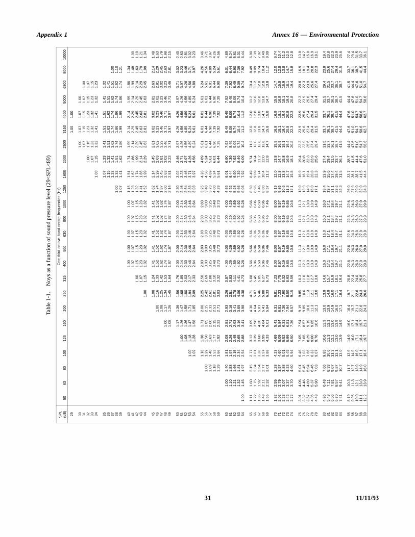
Appendix 1 Annex 16 — Environmental Protection
31 11/11/93
Tabl
e 1-
1.N
oys
as
a f
unct
ion
of s
oun
d pr
essu
re le
vel (
29<
SP
L<89
)
SP
L(d
B)
On
e-th
ird o
ctav
e ba
nd c
ent
re f
requ
enc
ies
(Hz)
506
380
100
125
160
200
250
315
400
500
630
800
1000
125
01
600
2000
250
03
150
4000
500
063
00
8000
100
00
291.
001
.00
301.
001.
071
.07
1.00
311.
071.
151
.15
1.07
1.0
032
1.0
01.
151.
231
.23
1.15
1.0
733
1.0
71.
231.
321
.32
1.23
1.1
534
1.00
1.1
51.
321.
411
.41
1.32
1.2
3
351.
071
.23
1.41
1.51
1.5
11.
411.
32
361.
151
.32
1.51
1.62
1.6
21.
511.
41
371.
231
.41
1.62
1.74
1.7
41.
621.
51
1.0
038
1.0
01.
321
.51
1.74
1.86
1.8
61.
741.
62
1.1
039
1.0
71.
411
.62
1.86
1.99
1.9
91.
861.
74
1.2
1
401.
001
.00
1.0
01.
001
.00
1.1
51.
511
.74
1.99
2.14
2.1
41.
991.
86
1.3
441
1.07
1.0
71
.07
1.07
1.0
71
.23
1.62
1.8
62.
142.
292
.29
2.14
1.9
91
.48
1.00
421
.00
1.15
1.1
51
.15
1.15
1.1
51
.32
1.74
1.9
92.
292.
452
.45
2.29
2.1
41
.63
1.10
431
.07
1.23
1.2
31
.23
1.23
1.2
31
.41
1.86
2.1
42.
452.
632
.63
2.45
2.2
91
.79
1.21
441
.00
1.1
51.
321
.32
1.3
21.
321
.32
1.5
21.
992
.29
2.63
2.81
2.8
12.
632.
45
1.9
91.
34
451
.08
1.2
41.
411
.41
1.4
11.
411
.41
1.6
22.
142
.45
2.81
3.02
3.0
22.
812.
63
2.1
41.
4846
1.00
1.1
61
.33
1.52
1.5
21
.52
1.52
1.5
21
.74
2.29
2.6
33.
023.
233
.23
3.02
2.8
12
.29
1.63
471.
081
.25
1.4
21.
621
.62
1.6
21.
621
.62
1.8
72.
452
.81
3.23
3.46
3.4
63.
233.
02
2.4
51.
7948
1.0
01.
171
.34
1.5
31.
741
.74
1.7
41.
741
.74
2.0
02.
633
.02
3.46
3.71
3.7
13.
463.
23
2.6
31.
9849
1.0
81.
261
.45
1.6
41.
871
.87
1.8
71.
871
.87
2.1
42.
813
.23
3.71
3.97
3.9
73.
713.
46
2.8
12.
15
501
.17
1.36
1.5
61
.76
2.00
2.0
02
.00
2.00
2.0
02
.30
3.02
3.4
63.
974.
264
.26
3.97
3.7
13
.02
2.40
511
.00
1.2
61.
471
.68
1.8
92.
142
.14
2.1
42.
142
.14
2.4
63.
233
.71
4.26
4.56
4.5
64.
263.
97
3.2
32.
6352
1.0
81
.36
1.58
1.8
02
.03
2.30
2.3
02
.30
2.30
2.3
02
.64
3.46
3.9
74.
564.
894
.89
4.56
4.2
63
.46
2.81
531.
001
.18
1.4
71.
711
.94
2.1
72.
462
.46
2.4
62.
462
.46
2.8
33.
714
.26
4.89
5.24
5.2
44.
894.
56
3.7
13.
0254
1.09
1.2
81
.58
1.85
2.0
92
.33
2.64
2.6
42
.64
2.64
2.6
43
.03
3.97
4.5
65.
245.
615
.61
5.24
4.8
93
.97
3.23
551.
181
.38
1.7
12.
002
.25
2.5
02.
832
.83
2.8
32.
832
.83
3.2
54.
264
.89
5.61
6.01
6.0
15.
615.
24
4.2
63.
4656
1.0
01.
291
.50
1.8
52.
152
.42
2.6
93.
033
.03
3.0
33.
033
.03
3.4
84.
565
.24
6.01
6.44
6.4
46.
015.
61
4.5
63.
7157
1.0
91.
401
.63
2.0
02.
332
.61
2.8
83.
253
.25
3.2
53.
253
.25
3.7
34.
895
.61
6.44
6.90
6.9
06.
446.
01
4.8
93.
9758
1.1
81.
531
.77
2.1
52.
512
.81
3.1
03.
483
.48
3.4
83.
483
.48
4.0
05.
246
.01
6.90
7.39
7.3
96.
906.
44
5.2
44.
2659
1.2
91.
661
.92
2.3
32.
713
.03
3.3
23.
733
.73
3.7
33.
733
.73
4.2
95.
616
.44
7.39
7.92
7.9
27.
396.
90
5.6
14.
56
601
.00
1.4
01.
812
.08
2.5
12.
933
.26
3.5
74.
004
.00
4.0
04.
004
.00
4.5
96.
016
.90
7.92
8.49
8.4
97.
927.
39
6.0
14.
8961
1.1
01
.53
1.97
2.2
62
.71
3.16
3.5
13
.83
4.29
4.2
94
.29
4.29
4.2
94
.92
6.44
7.3
98.
499.
099
.09
8.49
7.9
26
.44
5.24
621
.21
1.6
62.
152
.45
2.9
33.
413
.78
4.1
14.
594
.59
4.5
94.
594
.59
5.2
86.
907
.92
9.09
9.74
9.7
49.
098.
49
6.9
05.
6163
1.3
21
.81
2.34
2.6
53
.16
3.69
4.0
64
.41
4.92
4.9
24
.92
4.92
4.9
25
.66
7.39
8.4
99.
7410
.41
0.4
9.74
9.0
97
.39
6.01
641.
001
.45
1.9
72.
542
.88
3.4
13.
984
.38
4.7
35.
285
.28
5.2
85.
285
.28
6.0
67.
929
.09
10.4
11.2
11.
210
.49.
74
7.9
26.
44
651.
111
.60
2.1
52.
773
.12
3.6
94.
304
.71
5.0
85.
665
.66
5.6
65.
665
.66
6.5
08.
499
.74
11.2
12.0
12.
011
.210
.48
.49
6.90
661.
221
.75
2.3
43.
013
.39
3.9
84.
645
.07
5.4
56.
066
.06
6.0
66.
066
.06
6.9
69.
091
0.4
12.0
12.8
12.
812
.011
.29
.09
7.39
671.
351
.92
2.5
43.
283
.68
4.3
05.
015
.46
5.8
56.
506
.50
6.5
06.
506
.50
7.4
69.
741
1.2
12.8
13.8
13.
812
.812
.09
.74
7.92
681.
492
.11
2.7
73.
573
.99
4.6
45.
415
.88
6.2
76.
966
.96
6.9
66.
966
.96
8.0
010
.41
2.0
13.8
14.7
14.
713
.812
.81
0.4
8.49
691.
652
.32
3.0
13.
884
.33
5.0
15.
846
.33
6.7
37.
467
.46
7.4
67.
467
.46
8.5
711
.21
2.8
14.7
15.8
15.
814
.713
.81
1.2
9.09
701.
822
.55
3.2
84.
234
.69
5.4
16.
316
.81
7.2
38.
008
.00
8.0
08.
008
.00
9.1
912
.01
3.8
15.8
16.9
16.
915
.814
.71
2.0
9.74
712.
022
.79
3.5
74.
605
.09
5.8
46.
817
.33
7.7
58.
578
.57
8.5
78.
578
.57
9.8
512
.81
4.7
16.9
18.1
18.
116
.915
.81
2.8
10.4
722.
233
.07
3.8
85.
015
.52
6,3
17.
367
.90
8.3
29.
199
.19
9.1
99.
199
.19
10.
613
.81
5.8
18.1
19.4
19.
418
.116
.91
3.8
11.2
732.
463
.37
4.2
35.
455
.99
6.8
17.
948
.50
8.9
39.
859
.85
9.8
59.
859
.85
11.
314
.71
6.9
19.4
20.8
20.
819
.418
.11
4.7
12.0
742.
723
.70
4.6
05.
946
.50
7.3
68.
579
.15
9.5
910
.61
0.6
10.
610
.61
0.6
12.
115
.81
8.1
20.8
22.3
22.
320
.819
.41
5.8
12.8
753.
014
.06
5.0
16.
467
.05
7.9
49.
199
.85
10.
311
.31
1.3
11.
311
.31
1.3
13.
016
.91
9.4
22.3
23.9
23.
922
.320
.81
6.9
13.8
763.
324
.46
5.4
57.
037
.65
8.5
79.
851
0.6
11.
012
.11
2.1
12.
112
.11
2.1
13.
918
.12
0.8
23.9
25.6
25.
623
.922
.31
8.1
14.7
773.
674
.89
5.9
47.
668
.29
9.1
910
.61
1.3
11.
813
.01
3.0
13.
013
.01
3.0
14.
919
.42
2.3
25.6
27.4
27.
425
.623
.91
9.4
15.8
784.
065
.37
6.4
68.
339
.00
9.8
511
.31
2.1
12.
713
.91
3.9
13.
913
.91
3.9
16.
020
.82
3.9
27.4
29.4
29.
427
.425
.62
0.8
16.9
794.
495
.90
7.0
39.
079
.76
10.
612
.11
3.0
13.
614
.91
4.9
14.
914
.91
4.9
17.
122
.32
5.6
29.4
31.5
31.
529
.427
.42
2.3
18.1
804.
966
.48
7.6
69.
851
0.6
11.
313
.01
3.9
14.
616
.01
6.0
16.
016
.01
6.0
18.
423
.92
7.4
31.5
33.7
33.
731
.529
.42
3.9
19.4
815.
487
.11
8.3
310
.61
1.3
12.
113
.91
4.9
15.
717
.11
7.1
17.
117
.11
7.1
19.
725
.62
9.4
33.7
36.1
36.
133
.731
.52
5.6
20.8
826.
067
.81
9.0
711
.31
2.1
13.
014
.91
6.0
16.
918
.41
8.4
18.
418
.41
8.4
21.
127
.43
1.5
36.1
38.7
38.
736
.133
.72
7.4
22.3
836.
708
.57
9.8
712
.11
3.0
13.
916
.01
7.1
18.
119
.71
9.7
19.
719
.71
9.7
22.
629
.43
3.7
38.7
41.5
41.
538
.736
.12
9.4
23.9
847.
419
.41
10.
713
.01
3.9
14.
917
.11
8.4
19.
421
.12
1.1
21.
121
.12
1.1
24.
331
.53
6.1
41.5
44.4
44.
441
.538
.73
1.5
25.6
858.
191
0.3
11.
713
.91
4.9
16.
018
.41
9.7
20.
822
.62
2.6
22.
622
.62
2.6
26.
033
.73
8.7
44.4
47.6
47.
644
.441
.53
3.7
27.4
869.
951
1.3
12.
714
.91
6.0
17.
119
.72
1.1
22.
424
.32
4.3
24.
324
.32
4.3
27.
936
.14
1.5
47.6
51.0
51.
047
.644
.43
6.1
29.4
8710
.01
2.1
13.
916
.01
7.1
18.
421
.12
2.6
24.
026
.02
6.0
26.
026
.02
6.0
29.
038
.74
4.4
51.0
54.7
54.
751
.047
.63
8.7
31.5
8811
.11
3.0
14.
917
.11
8.4
19.
722
.62
4.3
25.
827
.92
7.9
27.
927
.92
7.9
32.
041
.54
7.6
54.7
58.6
58.
654
.751
.04
1.5
33.7
8912
.21
3.9
16.
018
.41
9.7
21.
124
.32
6.0
27.
729
.92
9.9
29.
929
.92
9.9
34.
344
.45
1.0
58.6
62.7
62.
758
.654
.74
4.4
36.1
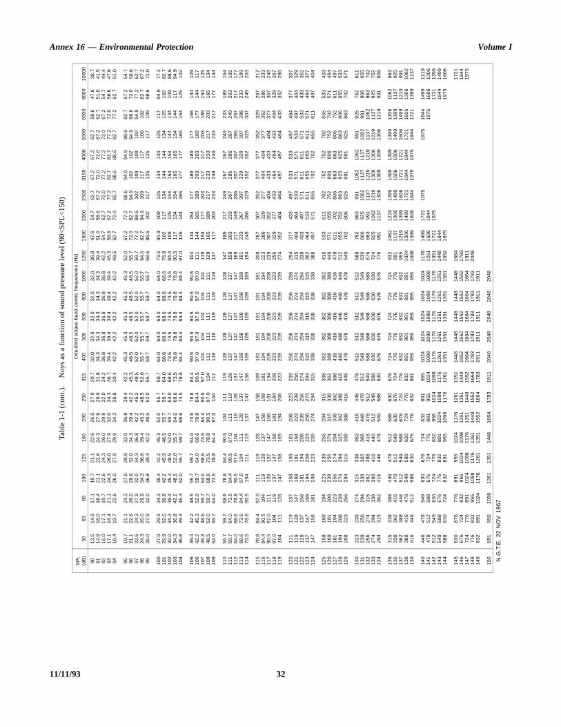
Annex 16 — Environmental Protection Volume I
11/11/93 32
Tabl
e 1-
1 (c
ont
.).
Noy
s as
a f
unc
tion
of s
ound
pre
ssur
e le
vel (
90<
SP
L<
150
)
SP
L(d
B)
On
e-th
ird o
ctav
e ba
nd c
ent
re f
requ
enc
ies
(Hz)
506
380
100
125
160
200
250
315
400
500
630
800
1000
125
01
600
2000
250
03
150
4000
500
063
00
8000
100
00
9013
.51
4.9
17.
119
.72
1.1
22.
626
.02
7.9
29.
732
.03
2.0
32.
032
.03
2.0
36.
847
.65
4.7
62.7
67.2
67.
262
.758
.64
7.6
38.7
9114
.91
6.0
18.
421
.12
2.6
24.
327
.92
9.9
31.
834
.33
4.3
34.
334
.33
4.3
39.
451
.05
8.6
67.2
72.0
72.
067
.262
.75
1.0
41.5
9216
.01
7.1
19.
722
.62
4.3
26.
029
.93
2.0
34.
236
.83
6.8
36.
836
.83
6.8
42.
254
.76
2.7
72.0
77.2
77.
272
.067
.25
4.7
44.4
9317
.11
8.4
21.
124
.32
6.0
27.
932
.03
4.3
36.
739
.43
9.4
39.
439
.43
9.4
45.
358
.66
7.2
77.2
82.7
82.
777
.272
.05
8.6
47.6
9418
.41
9.7
22.
626
.02
7.9
29.
934
.33
6.8
39.
442
.24
2.2
42.
242
.24
2.2
48.
562
.77
2.0
82.7
88.6
88.
682
.777
.26
2.7
51.0
9519
.72
1.1
24.
327
.92
9.9
32.
036
.83
9.4
42.
245
.34
5.3
45.
345
.34
5.3
52.
067
.27
7.2
88.6
94.9
94.
988
.682
.76
7.2
54.7
9621
.12
2.6
26.
029
.93
2.0
34.
339
.44
2.2
45.
348
.54
8.5
48.
548
.54
8.5
55.
772
.08
2.7
94.9
102
102
94.9
88.6
72.
058
.697
22.6
24.
32
7.9
32.0
34.
33
6.8
42.2
45.
34
8.5
52.0
52.
05
2.0
52.0
52.
05
9.7
77.2
88.
610
21
0910
910
294
.97
7.2
62.7
9824
.32
6.0
29.
934
.33
6.8
39.
445
.34
8.5
52.
055
.75
5.7
55.
755
.75
5.7
64.
082
.79
4.9
109
117
117
109
102
82.
767
.299
26.0
27.
93
2.0
36.8
39.
44
2.2
48.5
52.
05
5.7
59.7
59.
75
9.7
59.7
59.
76
8.6
88.6
102
117
125
125
117
109
88.
672
.0
100
27.9
29.
93
4.3
39.4
42.
24
5.3
52.0
55.
75
9.7
64.0
64.
06
4.0
64.0
64.
07
3.5
94.9
109
125
134
134
125
117
94.
977
.21
0129
.93
2.0
36.
842
.24
5.3
48.
555
.75
9.7
64.
068
.66
8.6
68.
668
.66
8.6
78.
81
0211
713
41
4414
413
41
2510
282
.71
0232
.03
4.3
39.
445
.34
8.5
52.
059
.76
4.0
68.
673
.57
3.5
73.
573
.57
3.5
84.
41
0912
514
41
5415
414
41
3410
988
.61
0334
.33
6.8
42.
248
.55
2.0
55.
764
.06
8.6
73.
578
.87
8.8
78.
878
.87
8.8
90.
51
1713
415
41
6516
515
41
4411
794
.91
0436
.83
9.4
45.
352
.05
5.7
59.
768
.67
3.5
78.
884
.48
4.4
84.
484
.48
4.4
97.
01
2514
416
51
7717
716
51
5412
510
2
105
39.4
42.
24
8.5
55.7
59.
76
4.0
73.5
78.
88
4.4
90.5
90.
59
0.5
90.5
90.
510
41
3415
417
71
8918
917
71
6513
410
91
0642
.24
5.3
52.
059
.76
4.0
68.
678
.88
4.4
90.
597
.09
7.0
97.
097
.09
7.0
111
144
165
189
203
203
189
177
144
117
107
45.3
48.
55
5.7
64.0
68.
67
3.5
84.4
90.
59
7.0
104
104
104
104
104
119
154
177
203
217
217
203
189
154
125
108
48.5
52.
05
9.7
68.6
73.
57
8.8
90.5
97.
010
41
1111
111
11
1111
112
81
6518
921
72
3323
321
72
0316
513
41
0952
.05
5.7
64.
073
.57
8.8
84.
497
.01
0411
11
1911
911
91
1911
913
71
7720
323
32
4924
923
32
1717
714
4
110
55.7
59.
76
8.6
78.8
84.
49
0.5
104
111
119
128
128
128
128
128
147
189
217
249
267
267
249
233
189
154
111
59.7
64.
07
3.5
84.4
90.
59
7.0
111
119
128
137
137
137
137
137
158
203
233
267
286
286
267
249
203
165
112
64.0
68.
67
8.8
90.5
97.
010
41
191
2813
71
4714
714
71
4714
716
92
1724
928
63
0730
728
62
6721
717
71
1368
.67
3.5
84.
497
.01
0411
11
281
3714
71
5815
815
81
5815
818
12
3326
730
73
2932
930
72
8623
318
91
1473
.57
8.8
90.
51
041
1111
91
371
4715
81
6916
916
91
6916
919
42
4928
632
93
5235
232
93
0724
920
3
115
78.8
84.
49
7.0
111
119
128
147
158
169
181
181
181
181
181
208
267
307
352
377
377
352
329
267
217
116
84.4
90.
510
41
191
2813
71
581
6918
11
9419
419
41
9419
422
32
8632
937
74
0440
437
73
5228
623
31
1790
.59
7.0
111
128
137
147
169
181
194
208
208
208
208
208
239
307
352
404
433
433
404
377
307
249
118
97.0
104
119
137
147
158
181
194
208
223
223
223
223
223
256
329
377
433
464
464
433
404
329
267
119
104
111
128
147
158
169
194
208
223
239
239
239
239
239
274
352
404
464
497
497
464
433
352
286
120
111
119
137
158
169
181
208
223
239
256
256
256
256
256
294
377
433
497
533
533
497
464
377
307
121
119
128
147
169
181
194
223
239
256
274
274
274
274
274
315
404
464
533
571
571
533
497
404
329
122
128
137
158
181
194
208
239
256
274
294
294
294
294
294
338
433
497
571
611
611
571
533
433
352
123
137
147
169
194
208
223
256
274
294
315
315
315
315
315
362
464
533
611
655
655
611
571
464
377
124
147
158
181
208
223
239
274
294
315
338
338
338
338
338
388
497
571
655
702
702
655
611
497
404
125
158
169
194
223
239
256
294
315
338
362
362
362
362
362
416
533
611
702
752
752
702
655
533
433
126
169
181
208
239
256
274
315
338
362
388
388
388
388
388
446
571
655
752
806
806
752
702
571
464
127
181
194
223
256
274
294
338
362
388
416
416
416
416
416
478
611
702
806
863
863
806
752
611
497
128
194
208
239
274
294
315
362
388
416
446
446
446
446
446
512
655
752
863
925
925
863
806
655
533
129
208
223
256
294
315
338
388
416
446
478
478
478
478
478
549
702
806
925
991
991
925
863
702
571
130
223
239
274
315
338
362
416
446
478
512
512
512
512
512
588
752
863
991
106
210
6299
19
2575
261
11
312
392
5629
43
383
6238
84
464
7851
25
4954
954
95
4954
963
08
0692
51
062
113
711
371
062
991
806
655
132
256
274
315
362
388
416
478
512
549
588
588
588
588
588
676
863
991
113
71
219
1219
113
710
62
863
702
133
274
294
338
388
416
446
512
549
588
630
630
630
630
630
724
925
1062
121
91
306
1306
121
911
37
925
752
134
294
315
362
416
446
478
549
588
630
676
676
676
676
676
776
991
1137
130
61
399
1399
130
612
19
991
806
135
315
338
388
446
478
512
588
630
676
724
724
724
724
724
832
106
212
191
399
149
914
991
399
130
610
6286
31
363
383
6241
64
785
1254
96
306
7672
47
7677
677
67
7677
689
11
137
1306
149
91
606
1606
149
913
99
1137
925
137
362
388
446
512
549
588
676
724
776
832
832
832
832
832
955
121
913
991
606
172
117
211
606
149
912
1999
11
383
884
1647
85
495
8863
07
247
7683
28
9189
189
18
9189
11
024
130
614
991
721
184
418
441
721
160
613
061
062
139
416
446
512
588
630
676
776
832
891
955
955
955
955
955
109
81
399
1606
184
41
975
1975
184
417
21
1399
113
7
140
446
478
549
630
676
724
832
891
955
102
410
241
024
102
410
241
176
149
917
211
975
197
518
44
1499
121
91
414
785
1258
86
767
2477
68
919
551
024
109
810
981
098
109
810
981
261
160
618
4419
75
1606
130
61
425
125
4963
07
247
7683
29
5510
241
098
117
611
761
176
117
611
761
351
172
119
7517
211
399
143
549
588
676
776
832
891
102
410
981
176
126
112
611
261
126
112
611
448
184
418
441
499
144
588
630
724
832
891
955
109
811
761
261
135
113
511
351
135
113
511
552
197
519
751
606
145
630
676
776
891
955
102
41
176
1261
135
11
448
1448
144
81
448
1448
166
41
721
146
676
724
832
955
1024
109
81
261
1351
144
81
552
1552
155
21
552
1552
178
31
844
147
724
776
891
102
410
981
176
135
114
481
552
166
416
641
664
166
416
641
911
197
51
487
768
3295
51
098
1176
126
11
448
1552
166
41
783
1783
178
31
783
1783
204
81
498
328
911
024
117
612
611
351
155
216
641
783
191
119
111
911
191
119
11
150
891
955
109
81
261
1351
144
81
664
1783
191
12
048
2048
204
82
048
2048
N.G
.T.E
. 22
NO
V. 1
967
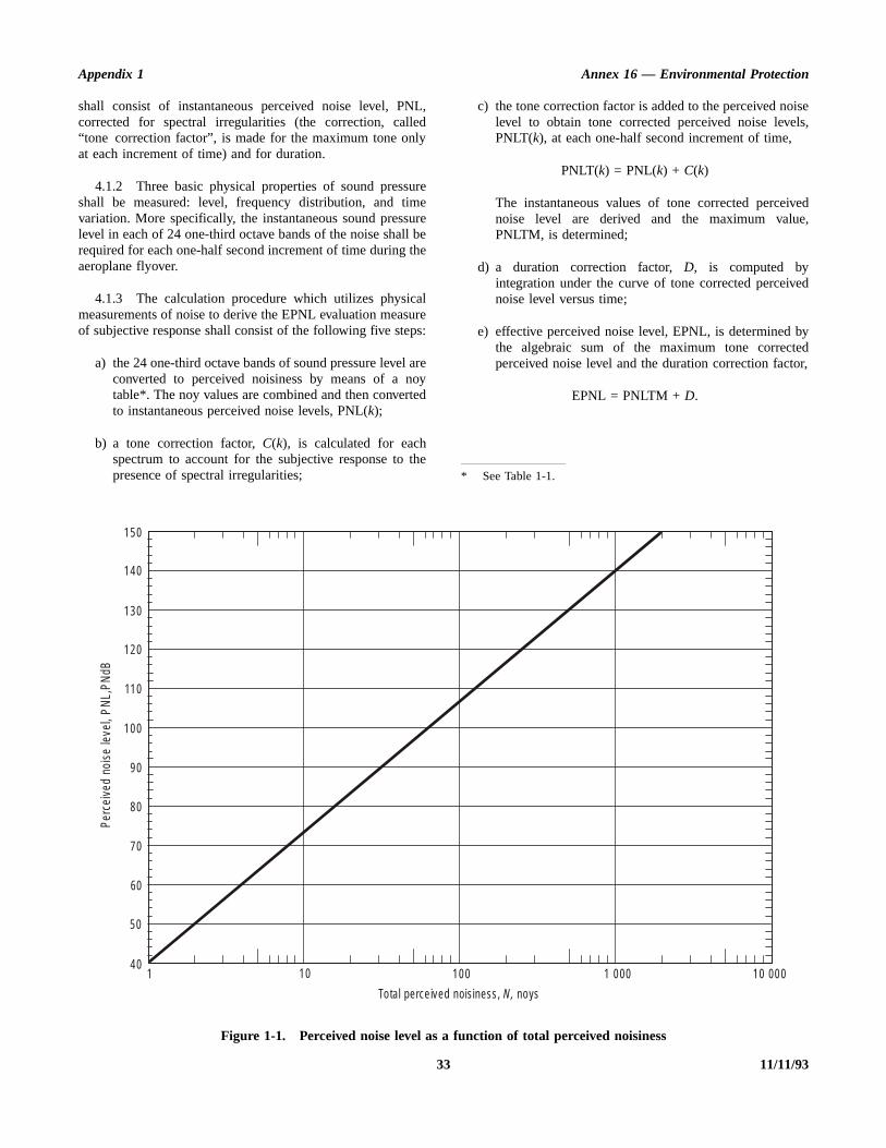
Appendix 1 Annex 16 — Environmental Protection
isels,
vede,
ed
byedor,
shall consist of instantaneous perceived noise level, PNL,corrected for spectral irregularities (the correction, called“tone correction factor”, is made for the maximum tone onlyat each increment of time) and for duration.
4.1.2 Three basic physical properties of sound pressureshall be measured: level, frequency distribution, and timevariation. More specifically, the instantaneous sound pressurelevel in each of 24 one-third octave bands of the noise shall berequired for each one-half second increment of time during theaeroplane flyover.
4.1.3 The calculation procedure which utilizes physicalmeasurements of noise to derive the EPNL evaluation measureof subjective response shall consist of the following five steps:
a) the 24 one-third octave bands of sound pressure level areconverted to perceived noisiness by means of a noytable*. The noy values are combined and then convertedto instantaneous perceived noise levels, PNL(k);
b) a tone correction factor, C(k), is calculated for eachspectrum to account for the subjective response to thepresence of spectral irregularities;
c) the tone correction factor is added to the perceived nolevel to obtain tone corrected perceived noise levePNLT(k), at each one-half second increment of time,
PNLT(k) = PNL(k) + C(k)
The instantaneous values of tone corrected perceinoise level are derived and the maximum valuPNLTM, is determined;
d) a duration correction factor, D, is computed byintegration under the curve of tone corrected perceivnoise level versus time;
e) effective perceived noise level, EPNL, is determined the algebraic sum of the maximum tone correctperceived noise level and the duration correction fact
EPNL = PNLTM + D.
* See Table 1-1.
33 11/11/93
Figure 1-1. Perceived noise level as a function of total perceived noisiness
150
140
130
120
110
100
90
80
70
60
50
401 10 100 1 000 10 000
To tal perce ived noisiness, noys N,
Perc
eive
d no
ise
leve
l, P
NL ,
PNdB

Annex 16 — Environmental Protection Volume I
that
be
ewure
4.2 Perceived noise level
4.2.1 Instantaneous perceived noise levels, PNL(k), shallbe calculated from instantaneous one-third octave band soundpressure levels, SPL(i,k), as follows:
Step 1. Convert each one-third octave band SPL(i,k), from50 to 10 000 Hz, to perceived noisiness, n(i,k), by referenceto Table 1-1, or to the mathematical formulation of the noytable given in Section 7.
Step 2. Combine the perceived noisiness values, n(i,k),found in Step 1 by the following formula:
N(k) = n(k) + 0.15
= 0.85 n(k) + 0.15
where n(k) is the largest of the 24 values of n(i,k) and N(k) isthe total perceived noisiness.
Step 3. Convert the total perceived noisiness, N(k), intoperceived noise level, PNL(k), by the following formula:
which is plotted in Figure 1-1. PNL(k) may also be obtainedby choosing N(k) in the 1 000 Hz column of Table 1-1 andthen reading the corresponding value of SPL(i,k) which, at1 000 Hz, equals PNL(k).
4.3 Correction for spectralirregularities
4.3.1 Noise having pronounced spectral irregularities (forexample, the maximum discrete frequency components ortones) shall be adjusted by the correction factor C(k) calculatedas follows:
Step 1. Starting with the corrected sound pressure level inthe 80 Hz one-third octave band (band number 3), calculate thechanges in sound pressure level (or “slopes”) in the remainderof the one-third octave bands as follows:
s(3,k) = no values(4,k) = SPL(4,k) – SPL(3,k)•••s(i,k) = SPL(i,k) – SPL[(i–1),k]•••s24,k) = SPL(24,k) – SPL(23,k)
Step 2. Encircle the value of the slope, s(i,k), where theabsolute value of the change in slope is greater than five; is, where
| ∆ s (i, k) | = | s (i, k) – s [(i – 1), k] | >5
Step 3.
a) If the encircled value of the slope s(i,k) is positive andalgebraically greater than the slope s[(i–1),k] encircleSPL(i,k).
b) If the encircled value of the slope s(i,k) is zero ornegative and the slope s[(i–1),k] is positive, encircleSPL[(i–1),k].
c) For all other cases, no sound pressure level value is toencircled.
Step 4. Omit all SPL(i,k) encircled in Step 3 and computenew adjusted sound pressure levels SPL′(i,k) as follows:
a) For non-encircled sound pressure levels, let the nsound pressure levels equal the original sound presslevels, SPL′(i,k) ≡ SPL(i,k).
Table 1-2. Tone correction factorsPNL(k) = 40.0 +
10log N(k)
log 2
[ n i k,( ) ]i 1=
24
∑ n k( )–
n i k,( )i 1=
24
∑
Frequency/, Hz
Leveldifference
F, dB
Tonecorrection
C, dB
50 < / < 500 3* < F < 2020 < F
F/63a
500 < / < 5 000 3* < F < 2020 < F
F/36b
5 000 < / < 10 000 3* < F < 2020 < F
F/63a
* See Step 8, 4.3.1.
11/11/93 34

Appendix 1 Annex 16 — Environmental Protection
n
ult(orana
owised
tolar
el,ne
ae at
e
esis,(
b) For encircled sound pressure levels in bands 1 to 23inclusive, let the new sound pressure level equal thearithmetic average of the preceding and following soundpressure levels:
SPL′(i,k) = (1/2) { SPL[(i–1),k] + SPL[(i+1),k] }
c) If the sound pressure level in the highest frequency band(i = 24) is encircled, let the new sound pressure level inthat band equal
SPL′(24,k) = SPL(23,k) + s(23,k)
Step 5. Recompute new slopes s′(i,k), including one for animaginary 25th band, as follows:
s′(3,k) ≡ s′(4,k)s′(4,k) = SPL′(4,k) – SPL′(3,k)•••s′(i,k) = SPL′(i,k) – SPL′[(i–1),k]•••s′(24,k) = SPL′(24,k) – SPL′(23,k)s′(25,k) ≡ s′(24,k)
Step 6. For i from 3 to 23, compute the arithmetic averageof the three adjacent slopes as follows:
ÿ (i,k) = (1/3) { s′(i,k) + s′[(i+1),k] + s′[(i+2),k] }
Step 7. Compute final one-third octave-band backgroundsound pressure levels, SPL″(i,k), by beginning with bandnumber 3 and proceeding to band number 24 as follows:
SPL″(3,k) ≡ SPL(3,k)SPL″(4,k) = SPL″(3,k) + ÿ (3,k)•••SPL″(i,k) = SPL″[(i–1),k] + ÿ (i–1),k]•••SPL″(24,k) = SPL″(23,k) + ÿ (23,k)
Step 8. Calculate the differences, F(i,k), between theoriginal sound pressure level and the final background soundpressure level as follows:
F(i,k) = SPL(i,k) – SPL″(i,k)
and note only values equal to or greater than three.
Step 9. For each of the relevant one-third octave bands (3to 24), determine tone correction factors from the soundpressure level differences F(i,k) and Table 1-2.
Step 10. Designate the largest of the tone correctiofactors, determined in Step 9, as C(k). An example of thetone correction procedure is given in Table 1-3.
Tone corrected perceived noise levels PNLT(k) shall bedetermined by adding the C(k) values to correspondingPNLT(k) values, that is,
PNLT(k) = PNL(k) + C(k)
For any i-th one-third octave band, at any k-th increment oftime, for which the tone correction factor is suspected to resfrom something other than (or in addition to) an actual tone any spectral irregularity other than aeroplane noise), additional analysis shall be made using a filter with bandwidth narrower than one-third of an octave. If the narrband analysis corroborates these suspicions, then a revvalue for the background sound pressure level, SPL″(i,k), shallbe determined from the narrow band analysis and usedcompute a revised tone correction factor for that particuone-third octave band.
4.4 Maximum tone correctedperceived noise level
4.4.1 The maximum tone corrected perceived noise levPNLTM, shall be the maximum calculated value of the tocorrected perceived noise level PNLT(k). It shall be calculatedin accordance with the procedure of 4.3. To obtain satisfactory noise time history, measurements shall be madhalf-second time intervals.
Note.— Figure 1-2 is an example of a flyover noise timhistory where the maximum value is clearly indicated.
4.4.2 If there are no pronounced irregularities in thspectrum, even when examined by a narrow-band analythen the procedure of 4.3 shall be disregarded since PNLTk)would be identically equal to PNL(k). For this case, PNLTMshall be the maximum value of PNL(k) and would equalPNLM.
4.5 Duration correction
4.5.1 The duration correction factor D determined by theintegration technique shall be defined by the expression:
D = 10 log – PNLTM
where T is a normalizing time constant, PNLTM is themaximum value of PNLT.
1T--- anti
PNLT10
----------------log tdt 1( )
t 2( )
∫
35 11/11/93

Annex 16 — Environmental Protection Volume I
11/11/93 36
Table 1-3. Example of tone correction calculation for a turbofan engine
Band(i)
fHz
SPLdB
SdB
Step1
1∆S1dB
Step2
SPL′dB
Step4
S′dB
Step5
þdB
Step6
SPL″dB
Step7
FdB
Step8
CdB
Step9
1 50 — — — — — — — — —
2 63 — — — — — — — — —
3 80 70 — — 70 – 8 – 2a 70 —
4 100 62 – 8 — 62 – 8 + 3a 67b —
5 125 70 + 8 16 71 + 9 + 6b 71 —
6 160 80 +10 2 80 + 9 + 2b 77b —
7 200 82 + 2 8 82 +2 – 1a 80a —
8 250 83 +1 1 79 – 3 – 1a 79 4 b
9 315 76 – 7 8 76 – 3 +1a 77b —
10 400 80 + 4 11 78 + 2 + 1 78 —
11 500 80 0 4 80 + 2 0 79 —
12 630 79 – 1 1 79 – 1 0 79 —
13 800 78 – 1 0 78 – 1 –1a 79 —
14 1 000 80 +2 3 80 + 2 –1b 78b —
15 1 250 78 – 2 4 78 – 2 –1a 78 —
16 1 600 76 – 2 0 76 – 2 +1a 77b —
17 2 000 79 +3 5 79 + 3 + 1 78 —
18 2 500 85 +6 3 79 0 –1a 79 6 2
19 3 150 79 – 6 12 79 0 – 2b 78b —
20 4 000 78 – 1 5 78 – 1 – 6a 76 —
21 5 000 71 – 7 6 71 – 7 – 8 69b —
22 6 300 60 –11 4 60 –11 – 8b 61b —
23 8 000 54 – 6 5 54 – 6 – 8 53 —
24 10 000 45 – 9 3 45 – 9 — 45 —
– 9
Step 1 ③ (i) – ③ (i – 1) Step 6 [⑦ (i) + ⑦ (i + 1) ++ ⑦ (i + 2)] ÷ 3Step 2 |④ (i) – ④ (i – 1)|
Step 3 see instructions Step 7 ⑨ (i – 1) + ⑧ (i – 1)
Step 4 see instructions Step 8 ③ (i) – ⑨ (i)
Step 5 ⑥ (i) – ⑥ (i – 1) Step 9 see Table 1-2
1 2 3 4 5 6 7 8 9 10 11

Appendix 1 Annex 16 — Environmental Protection
ed
d
sase
f
4.5.1.1 If PNLTM is greater than 100 TPNdB, t(1) shallbe the first point of time after which PNLT becomes greaterthan PNLTM – 10 and t(2) shall be the point of time afterwhich PNLT remains constantly less than PNLTM – 10.
4.5.1.2 If PNLTM is less than 100 TPNdB, t(1) shall bethe first point of time after which PNLT becomes greater than90 TPNdB and t(2) shall be the point of time after whichPNLT remains constantly less than 90 TPNdB.
4.5.1.3 If PNLTM is less than 90 TPNdB, the durationcorrection shall be taken as equal to 0.
4.5.2 Since PNLT is calculated from measured values ofSPL, there will, in general, be no obvious equation for PNLTas a function of time. Consequently, the equation shall berewritten with a summation sign instead of an integral sign asfollows:
D = 10 log – PNLTM
where ∆t is the length of the equal increments of time forwhich PNLT(k) is calculated and d is the time interval to thenearest 1.0 s during which PNLT(k) remains greater or equaleither to PNLTM – 10 or to 90 according to the cases specifiedin 4.5.1.1 to 4.5.1.3 above.
4.5.3 To obtain a satisfactory history of the perceivnoise level,
a) half-second time intervals for ∆t, or
b) a shorter time interval with approved limits anconstants
shall be used.
4.5.4 The following values for T and ∆t shall be used incalculating D in the procedure given in 4.5.2:
T = 10 s, and∆t = 0.5 s
Using the above values, the equation for D becomes
D = 10 log – PNLTM – 13
where the integer d is the duration time defined by the pointcorresponding to the values PNLTM – 10 or 90 as the cmay be.
4.5.5 If in the procedures given in 4.5.2, the limits oPNLTM – 10 or 90 fall between the calculated PNLT(k)values (the usual case), the PNLT(k) values defining the
1T---
∆t antiPNLT k( )
10-----------------------log⋅
k 0=
d ∆t⁄
∑anti
PNLT k( )10
-----------------------log
k 0=
2d
∑
37 11/11/93
Figure 1-2. Example of perceived noise level corrected for tonesas a function of aircraft flyover time
∆t
h
d
P N LT M
P N LT ( )k
t(1) t(2)
F lyo ve r tim e , seco n d st
Tone
cor
rect
ed p
erce
ived
noi
se le
vel P
NLT
, TP
NdB
Annex 16 — Environmental Protection Volume I
er, be
e
nd
s;
ear
ne orom
achrthe
rm-plingcezed
ineted.
theise
Cgir
limits of the duration interval shall be chosen from thePNLT(k) values closest to PNLTM – 10 or 90 as the casemay be.
4.6 Effective perceived noise level
4.6.1 The total subjective effect of an aeroplane flyover,designated “effective perceived noise level”, EPNL, shall beequal to the algebraic sum of the maximum value of the tonecorrected perceived noise level, PNLTM, and the durationcorrection, D. That is,
EPNL = PNLTM + D
where PNLTM and D are calculated in accordance with theprocedures given in 4.2, 4.3, 4.4 and 4.5. If the durationcorrection D is negative and greater than PNLTM – 90 inabsolute values, D shall be taken as equal to 90 – PNLTM.
5. REPORTING OF DATA TO THECERTIFICATING AUTHORITY AND
CORRECTING MEASURED DATA
5.1 General
5.1.1 Data representing physical measurements orcorrections to measured data shall be recorded in permanentform and appended to the record except that corrections tomeasurements for normal equipment response deviations neednot be reported. All other corrections shall be approved.Attempts shall be made to keep to a minimum the individualerrors inherent in each of the operations employed in obtainingthe final data.
5.2 Data reporting
5.2.1 Measured and corrected sound pressure levels shallbe presented in one-third octave band levels obtained withequipment conforming to the Standards described in Section 3of this appendix.
5.2.2 The type of equipment used for measurement andanalysis of all acoustic aeroplane performance andmeteorological data shall be reported.
5.2.3 The following atmospheric environmental data,measured immediately before, after, or during each test at theobservation points prescribed in Section 2 of this appendixshall be reported:
a) air temperature and relative humidity;
b) maximum, minimum, and average wind velocities;
c) atmospheric pressure.
5.2.4 Comments on local topography, ground covand events that might interfere with sound recordings shallreported.
5.2.5 The following aeroplane information shall breported:
a) type, model, serial numbers (if any) of aeroplane aengines;
b) gross dimensions of aeroplane and location of engine
c) aeroplane gross mass for each test run;
d) aeroplane configuration such as flap and landing gposition;
e) indicated airspeed in kilometres per hour (knots);
f) engine performance in terms of net thrust, engipressure ratios, jet exhaust temperatures and fancompressor shaft rotational speeds as determined fraeroplane instruments and manufacturer’s data;
g) aeroplane height above ground determined by method independent of cockpit instrumentation suas radar tracking, theodolite triangulation, ophotographic scaling techniques to be approved by certification authorities.
5.2.6 Aeroplane speed and position and engine perfoance parameters shall be recorded at an approved samrate sufficient to correct to the noise certification referenconditions prescribed in this section and shall be synchroniwith the noise measurement.
5.2.6.1 Lateral position relative to the extended centre lof the runway, configuration and gross mass shall be repor
5.3 Noise certification referenceconditions
5.3.1 Aeroplane position and performance data and noise measurements shall be corrected to the following nocertification reference conditions:
a) meteorological conditions:
1) sea level atmospheric pressure of 1 013.25 hPa;
2) ambient air temperature of 25°C, i.e. ISA + 10°except that, at the discretion of the certificatinauthority, an alternative reference ambient atemperature of 15°C, i.e. ISA may be used;
3) relative humidity of 70 per cent; and
4) zero wind;
11/11/93 38

Appendix 1 Annex 16 — Environmental Protection
est
in
berededs
theny
heved
entachtedheor isthefor
ofheachentultise
entbe isl be
b) aeroplane conditions:
1) maximum take-off mass and landing mass at whichnoise certification is requested;
2) approach angle of 3°; and
3) aeroplane height of 120 m (395 ft) above theapproach noise measuring station.
5.4 Data correction
5.4.1 The noise data shall be corrected to the noisecertification reference conditions as stated in 5.3. Themeasured atmospheric conditions shall be those obtained inaccordance with Section 2 of this appendix. Atmosphericattenuation of sound requirements are given in Section 8 ofthis appendix. If a reference ambient air temperature of 15°Cis used (see 5.3.1 a) 2)) a further correction of +1 EPNdB shallbe added to the noise levels obtained at the flyovermeasurement point.
5.4.2 The measured flight path shall be corrected by anamount equal to the difference between the applicant’spredicted flight paths for the test conditions and for the noisecertification reference conditions.
Note.— Necessary corrections relating to aeroplane flightpath or performance may be derived from approved data otherthan certification test data.
5.4.2.1 The flight path correction procedure for approachnoise shall be made with reference to a fixed aeroplanereference height and the reference approach angle. Theeffective perceived noise level correction shall be less than2 EPNdB to allow for:
a) the aeroplane not passing vertically above the measuringpoint;
b) the difference between the reference height and theheight of the aeroplane’s ILS antenna from theapproach measuring point; and
c) the difference between the reference and the tapproach angles.
Note.— Detailed correction requirements are given Section 9 of this appendix.
5.4.3 Test results on specific measurement shall not accepted if the difference in EPNL computed from measudata and that corrected to reference conditions exce15 EPNdB.
5.4.4 If aeroplane sound pressure levels do not exceedambient sound pressure levels by at least 10 dB in aone-third octave band, approved corrections for tcontribution of ambient sound pressure level to the obsersound pressure level shall be applied.
5.5 Validity of results
5.5.1 Three average EPNL values and their 90 per cconfidence limits shall be produced from the test results, esuch value being the arithmetical average of the correcacoustical measurements for all valid test runs at tappropriate measurement point (take-off, approach sideline). If more than one acoustic measurement systemused at any single measurement location (such as for symmetrical sideline measuring points), the resulting data each test run shall be averaged as a single measurement.
5.5.2 The minimum sample size acceptable for eachthe three certification measuring points shall be six. Tsamples shall be large enough to establish statistically for eof the three average noise certification levels a 90 per cconfidence limit not exceeding ±1.5 EPNdB. No test resshall be omitted from the average process unless otherwspecified by the certification authorities.
5.5.3 The average EPNL values and their 90 per cconfidence limits obtained by the foregoing process shall those by which the noise performance of the aeroplaneassessed against the noise certification criteria, and shalreported.
39 11/11/93

Annex 16 — Environmental Protection Volume I
es
tion
essure
with
have
the
g
nge.
tead
6. NOMENCLATURE
6.1 Symbols and units
Note.— The meanings of the various symbols in thisappendix are as follows. It is recognized that differences mayexist in the units and meanings of similar symbols inAppendix 2.
Symbol Unit Meaning
antilog — Antilogarithm to the base 10.
C(k) dB Tone correction factor. The factor to be added to PNL(k) to account for the presence of spectral irregularitisuch as tones at the k-th increment of time.
d s Duration time. The length of the significant noise time history being the time interval between the limits oft(1)and t(2) to the nearest second.
D dB Duration correction. The factor to be added to PNLTM to account for the duration of the noise.
EPNL EPNdB Effective perceived noise level. The value of PNL adjusted for both the spectral irregularities and the duraof the noise. (The unit EPNdB is used instead of the unit dB.)
f(i) Hz Frequency. The geometrical mean frequency for the i-th one-third octave band.
F(i,k) dB Delta-dB. The difference between the original sound pressure level and the final background sound prlevel in the i-th one-third octave band at the k-th interval of time.
h dB dB-down. The level to be subtracted from PNLTM that defines the duration of the noise.
H % Relative humidity. The ambient atmospheric relative humidity.
i — Frequency band index. The numerical indicator that denotes any one of the 24 one-third octave bandsgeometrical mean frequencies from 50 to 10 000 Hz.
k — Time increment index. The numerical indicator that denotes the number of equal time increments that elapsed from a reference zero.
log — Logarithm to the base 10.
log n(a) — Noy discontinuity co-ordinate. The log n value of the intersection point of the straight lines representing variation of SPL with log n.
M(b), M(c), etc. — Noy inverse slope. The reciprocals of the slopes of straight lines representing the variation of SPL with lon.
n noy Perceived noisiness. The perceived noisiness at any instant of time that occurs in a specified frequency ra
n(i,k) noy Perceived noisiness. The perceived noisiness at the k-th instant of time that occurs in the i-th one-third octaveband.
n(k) noy Maximum perceived noisiness. The maximum value of all of the 24 values of n(i) that occurs at the k-th instantof time.
N(k) noy Total perceived noisiness. The total perceived noisiness at the k-th instant of time calculated from the24-instantaneous values of n(i,k).
p(b), p(c), etc. — Noy slope. The slopes of straight lines representing the variation of SPL with log n.
PNL PNdB Perceived noise level. The perceived noise level at any instant of time. (The unit PNdB is used insof the unit dB.)
11/11/93 40
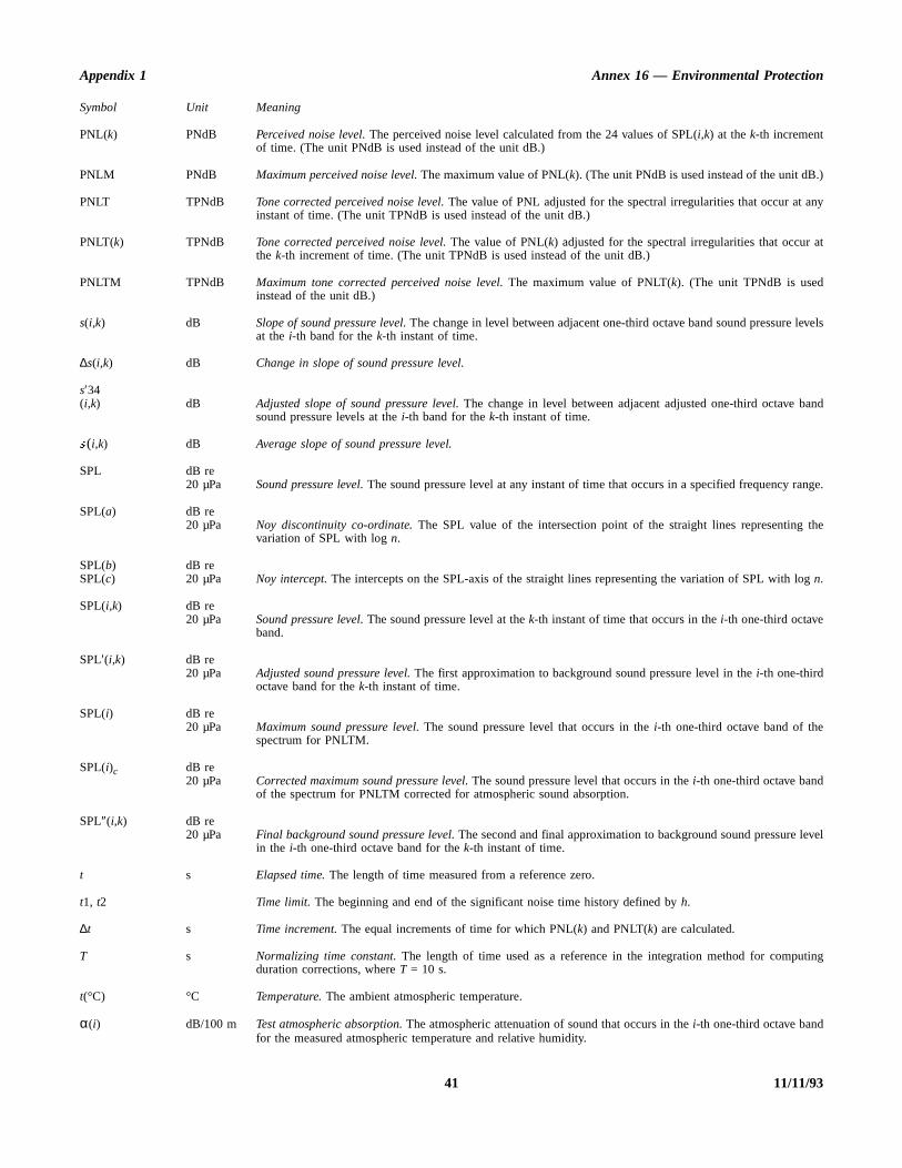
Appendix 1 Annex 16 — Environmental Protection
.)
any
at
levels
and
range.
the
log
level
ting
Symbol Unit Meaning
PNL(k) PNdB Perceived noise level. The perceived noise level calculated from the 24 values of SPL(i,k) at the k-th incrementof time. (The unit PNdB is used instead of the unit dB.)
PNLM PNdB Maximum perceived noise level. The maximum value of PNL(k). (The unit PNdB is used instead of the unit dB
PNLT TPNdB Tone corrected perceived noise level. The value of PNL adjusted for the spectral irregularities that occur at instant of time. (The unit TPNdB is used instead of the unit dB.)
PNLT(k) TPNdB Tone corrected perceived noise level. The value of PNL(k) adjusted for the spectral irregularities that occur the k-th increment of time. (The unit TPNdB is used instead of the unit dB.)
PNLTM TPNdB Maximum tone corrected perceived noise level. The maximum value of PNLT(k). (The unit TPNdB is usedinstead of the unit dB.)
s(i,k) dB Slope of sound pressure level. The change in level between adjacent one-third octave band sound pressureat the i-th band for the k-th instant of time.
∆s(i,k) dB Change in slope of sound pressure level.
s′34(i,k) dB Adjusted slope of sound pressure level. The change in level between adjacent adjusted one-third octave b
sound pressure levels at the i-th band for the k-th instant of time.
ÿ (i,k) dB Average slope of sound pressure level.
SPL dB re20 µPa Sound pressure level. The sound pressure level at any instant of time that occurs in a specified frequency
SPL(a) dB re20 µPa Noy discontinuity co-ordinate. The SPL value of the intersection point of the straight lines representing
variation of SPL with log n.
SPL(b) dB reSPL(c) 20 µPa Noy intercept. The intercepts on the SPL-axis of the straight lines representing the variation of SPL with n.
SPL(i,k) dB re20 µPa Sound pressure level. The sound pressure level at the k-th instant of time that occurs in the i-th one-third octave
band.
SPL′(i,k) dB re20 µPa Adjusted sound pressure level. The first approximation to background sound pressure level in the i-th one-third
octave band for the k-th instant of time.
SPL(i) dB re20 µPa Maximum sound pressure level. The sound pressure level that occurs in the i-th one-third octave band of the
spectrum for PNLTM.
SPL(i)c dB re20 µPa Corrected maximum sound pressure level. The sound pressure level that occurs in the i-th one-third octave band
of the spectrum for PNLTM corrected for atmospheric sound absorption.
SPL″(i,k) dB re20 µPa Final background sound pressure level. The second and final approximation to background sound pressure
in the i-th one-third octave band for the k-th instant of time.
t s Elapsed time. The length of time measured from a reference zero.
t1, t2 Time limit. The beginning and end of the significant noise time history defined by h.
∆t s Time increment. The equal increments of time for which PNL(k) and PNLT(k) are calculated.
T s Normalizing time constant. The length of time used as a reference in the integration method for compuduration corrections, where T = 10 s.
t(°C) °C Temperature. The ambient atmospheric temperature.
α(i) dB/100 m Test atmospheric absorption. The atmospheric attenuation of sound that occurs in the i-th one-third octave bandfor the measured atmospheric temperature and relative humidity.
41 11/11/93

Annex 16 — Environmental Protection Volume I
n is
l for
It is
noiseand test
ta toetween
noise
count
ue to
ht
e
ve
Symbol Unit Meaning
α(i)o dB/100 m Reference atmospheric absorption. The atmospheric attenuation of sound that occurs in the i-th one-third octaveband for a reference atmospheric temperature and relative humidity.
ß degrees First constant* climb angle.
γ degrees Second constant** climb angle.
δ degreesε degrees Thrust cutback angles. The angles defining the points on the take-off flight path at which thrust reductio
started and ended respectively.
η degrees Approach angle.
ηr degrees Reference approach angle.
θ degrees Take-off noise angle. The angle between the flight path and noise path for take-off operations. It is identicaboth measured and corrected flight paths.
λ degrees Approach noise angle. The angle between the flight path and the noise path for approach operations.identical for both measured and corrected flight paths.
∆1 EPNdB PNLT correction. The correction to be added to the EPNL calculated from measured data to account forlevel changes due to differences in atmospheric absorption and noise path length between reference conditions.
∆2 EPNdB Noise path duration correction. The correction to be added to the EPNL calculated from measured daaccount for noise level changes due to the noise duration because of differences in flyover altitude breference and test conditions.
∆3 EPNdB Mass correction. The correction to be added to the EPNL calculated from measured data to account forlevel changes due to differences between maximum mass and actual mass of the test aeroplane.
∆4 EPNdB Approach angle correction. The correction to be added to the EPNL calculated from measured data to acfor noise level changes due to differences between the reference and the test approach angles.
∆γ degrees∆δ degrees∆ε degrees
* Gear up, speed of at least V2 + 19 km/h (V2 + 10 kt), take-off thrust.** Gear up, speed of at least V2 + 19 km/h (V2 + 10 kt), after cut-back.
6.2 Flight profileidentification positions
∆AB∆ß
metresdegrees
Take-off profile changes. The algebraic changes in the basic parameters defining the take-off profile ddifferences between reference and test conditions.
Position Description
A Start of take-off roll.
B Lift-off.
C Start of first constant climb.
D Start of thrust reduction.
E Start of second constant climb.
Ec Start of second constant climb on corrected flight path.
F End of noise certification take-off flight path.
Fc End of noise certification corrected take-off flight path.
G Start of noise certification approach flight path.
Gr Start of noise certification approach on reference fligpath.
H Position on approach path directly above noismeasuring station.
Hr Position on reference approach path directly abonoise measuring station.
I Start of level-off.
Ir Start of level-off on reference approach flight path.
J Touchdown.
Position Description
11/11/93 42
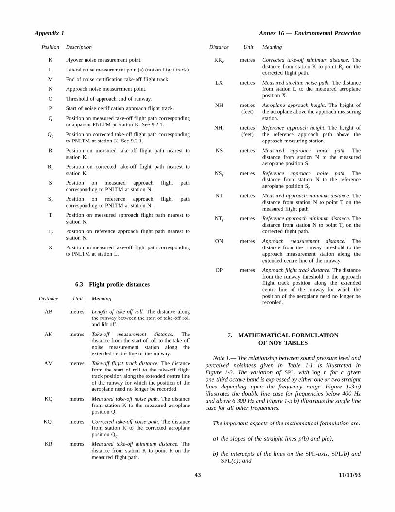
Appendix 1 Annex 16 — Environmental Protection
andin
ighta)Hzne
re:
e
ng
e
d
e
ee
h
e
6.3 Flight profile distances
7. MATHEMATICAL FORMULATIONOF NOY TABLES
Note 1.— The relationship between sound pressure level perceived noisiness given in Table 1-1 is illustrated Figure 1-3. The variation of SPL with log n for a givenone-third octave band is expressed by either one or two stralines depending upon the frequency range. Figure 1-3illustrates the double line case for frequencies below 400 and above 6 300 Hz and Figure 1-3 b) illustrates the single licase for all other frequencies.
The important aspects of the mathematical formulation a
a) the slopes of the straight lines p(b) and p(c);
b) the intercepts of the lines on the SPL-axis, SPL(b) andSPL(c); and
K Flyover noise measurement point.
L Lateral noise measurement point(s) (not on flight track).
M End of noise certification take-off flight track.
N Approach noise measurement point.
O Threshold of approach end of runway.
P Start of noise certification approach flight track.
Q Position on measured take-off flight path correspondingto apparent PNLTM at station K. See 9.2.1.
Qc Position on corrected take-off flight path correspondingto PNLTM at station K. See 9.2.1.
R Position on measured take-off flight path nearest tostation K.
Rc Position on corrected take-off flight path nearest tostation K.
S Position on measured approach flight pathcorresponding to PNLTM at station N.
Sr Position on reference approach flight pathcorresponding to PNLTM at station N.
T Position on measured approach flight path nearest tostation N.
Tr Position on reference approach flight path nearest tostation N.
X Position on measured take-off flight path correspondingto PNLTM at station L.
Distance Unit Meaning
AB metres Length of take-off roll. The distance alongthe runway between the start of take-off rolland lift off.
AK metres Take-off measurement distance. Thedistance from the start of roll to the take-offnoise measurement station along theextended centre line of the runway.
AM metres Take-off flight track distance. The distancefrom the start of roll to the take-off flighttrack position along the extended centre lineof the runway for which the position of theaeroplane need no longer be recorded.
KQ metres Measured take-off noise path. The distancefrom station K to the measured aeroplaneposition Q.
KQc metres Corrected take-off noise path. The distancefrom station K to the corrected aeroplaneposition Qc.
KR metres Measured take-off minimum distance. Thedistance from station K to point R on themeasured flight path.
Position Description
KRc metres Corrected take-off minimum distance. Thedistance from station K to point Rc on thecorrected flight path.
LX metres Measured sideline noise path. The distancefrom station L to the measured aeroplanposition X.
NH metres(feet)
Aeroplane approach height. The height ofthe aeroplane above the approach measuristation.
NHr metres(feet)
Reference approach height. The height ofthe reference approach path above thapproach measuring station.
NS metres Measured approach noise path. Thedistance from station N to the measureaeroplane position S.
NSr metres Reference approach noise path. Thedistance from station N to the referencaeroplane position Sr.
NT metres Measured approach minimum distance. Thedistance from station N to point T on themeasured flight path.
NTr metres Reference approach minimum distance. Thedistance from station N to point Tr on thecorrected flight path.
ON metres Approach measurement distance. Thedistance from the runway threshold to thapproach measurement station along thextended centre line of the runway.
OP metres Approach flight track distance. The distancefrom the runway threshold to the approacflight track position along the extendedcentre line of the runway for which theposition of the aeroplane need no longer brecorded.
Distance Unit Meaning
43 11/11/93

Annex 16 — Environmental Protection Volume I
nts a
below.
n,the
c) the coordinates of the discontinuity, SPL(a) and logn(a).
Note 2.— Mathematically the relationship is expressed asfollows:
Case 1: Figure 1-3 a): f < 400 HzCase 1: Figure 1-3 a): f > 6 300 Hz
a) SPL < SPL(a)
b) SPL > SPL(a)
c) log n < log n(a)
SPL = p(b) log n + SPL(b)
d) log n > log n(a)
SPL = p(c) log n + SPL(c)
Case 2: Figure 1-3 b): 400 < f < 6 300 Hz
SPL = p(c) log n + SPL(c)
Note 3.— If the reciprocals of the slopes are defined as:
M(b) = 1/p(b)
M(c) = 1/p(c)
the equations in Note 2 can be written,
Case 1: Figure 1-3 a): f < 400 HzCase 1: Figure 1-3 a): f > 6 300 Hz
a) SPL < SPL(a)
n = antilog M(b) [SPL – SPL(b)]
b) SPL > SPL(a)
n = antilog M(c) [SPL – SPL(c)]
c) log n < log n(a)
d) log n > log n(a)
Case 2: Figure 1-3 b): 400 < f < 6 300 Hz
n = antilog M(c) [SPL – SPL(c)]
Note 4.— Table 1-4 lists the values of the importaconstants necessary to calculate sound pressure level afunction of perceived noisiness.
8. SOUND ATTENUATION IN AIR
8.1 The atmospheric attenuation of sound shall determined in accordance with the procedure presented be
8.2 The relationship between sound attenuatiofrequency, temperature and humidity is expressed by following equations:
α(i) = 10[2.05 log (fo/1000) + 1.1394 × 10
–3θ – 1.916984] + η(δ)
× 10[log (fo) + 8.42994 × 10⁻³θ – 2.755624]
where
δ = 10(log H – 1.328924 + 3.179768 × 10⁻²θ)
× 10(–2.173716 × 10⁻⁴
θ2 + 1.7496 × 10
–6θ3)
η(δ) is given by Table 1-5 and fo by Table 1-6;
α(i) being the attenuation coefficient in dB/100 m;
θ being the temperature in °C; and
H being the relative humidity.
SPL(a) =p(c) SPL(b) – p(b) SPL(c)
p(c) – p(b)
log n(a) =SPL(c) – SPL(b)
p(b) – p(c)
n = antilogSPL – SPL(b)
p(b)
n = antilogSPL – SPL(c)
p(c)
n = antilogSPL – SPL(c)
p(c)
SPL(a) =M(b) SPL(b) – M(c) SPL(c)
M(b) – M(c)
log n(a) =M(b) M(c) [SPL(c) – SPL(b)]
M(c) – M(b)
SPL =log n + SPL(b)
M(b)
SPL =log n + SPL(c)
M(c)
SPL =log n + SPL(c)
M(c)
1010fo
------------
11/11/93 44

Appendix 1 Annex 16 — Environmental Protection
45 11/11/93
Figure 1-3. Sound pressure level as a function of perceived noisiness
a )
b )
SP L (a )
SP L (b )
SP L (c)
SP L (c)
Soun
d pr
essu
re le
vel,
SPL
Soun
d pr
essu
re le
vel,
SPL
0
0
log Log pe rc e ived no is iness , log
n (a )n
Log pe rc e ived no is iness , log n
ff < 400 H z > 6 300 H z
400 H z 6 300 H zf≤ ≤
s lope = p(c)
s lope = p (c )
s lope = p (b )
c
c
b

Annex 16 — Environmental Protection Volume I
11/11/93 46
Table 1-4. Constants for mathematically formulated noy values
Band(i)
f
Hz
M (b) SPL(b)dB
SPL(a)dB
M (c) SPL(c)dB
1 50 0.043478 64 91.0 0.030103 52
2 63 0.040570 60 85.9 51
3 80 0.036831 56 87.3 49
4 100 ” 53 79.9 47
5 125 0.035336 51 79.8 46
6 160 0.033333 48 76.0 45
7 200 ” 46 74.0 43
8 250 0.032051 44 74.9 42
9 315 0.030675 42 94.6 41
10 400 — — — 40
11 500 — — — 40
12 630 — — — 40
13 800 — — — 40
14 1 000 — — — 40
15 1 250 — — — 0.030103 38
16 1 600 — — — 0.029960 34
17 2 000 — — — 32
18 2 500 — — — 30
19 3 150 — — — 29
20 4 000 — — — 29
21 5 000 — — — 30
22 6 300 — — — 31
23 8 000 0.042285 37 44.3 34
24 10 000 0.042285 41 50.7 0.029960 37
NOT APPLICABLE

Appendix 1 Annex 16 — Environmental Protection
47 11/11/93
Table 1-5 Table 1-6
Table 1-7. Sound attenuation coefficient in dB/100 m
δ η δ η
0.00 0.000 2.30 0.4950.25 0.315 2.50 0.4500.50 0.700 2.80 0.4000.60 0.840 3.00 0.3700.70 0.930 3.30 0.3300.80 0.975 3.60 0.3000.90 0.996 4.15 0.2601.00 1.000 4.45 0.2451.10 0.970 4.80 0.2301.20 0.900 5.25 0.2201.30 0.840 5.70 0.2101.50 0.750 6.05 0.2051.70 0.670 6.50 0.2002.00 0.570 7.00 0.200
10.00 0.200
one-third octavecentre frequency
f0(Hz)
one-third octavecentre frequency
f0(Hz)
50 50 800 1 80063 63 1 000 1 00080 80 1 250 1 250100 100 1 600 1 600125 125 2 000 2 000160 160 2 500 2 500200 200 3 150 3 150250 250 4 000 4 000315 315 5 000 4 500400 400 6 300 5 600500 500 8 000 7 100630 630 10 000 9 000
Band centrefrequency
Relative humidity = 10 %
Temperature, °C
Hz –10 –5 0 5 10 15 20 25 30 35 40
50 0.1 0.1 0.0 0.0 0.0 0.0 0.0 0.0 0.0 0.0 0.063 0.1 0.1 0.1 0.1 0.0 0.0 0.0 0.0 0.0 0.0 0.080 0.1 0.1 0.1 0.1 0.1 0.0 0.0 0.0 0.1 0.1 0.1
100 0.1 0.2 0.1 0.1 0.1 0.1 0.1 0.1 0.1 0.1 0.1125 0.2 0.2 0.2 0.1 0.1 0.1 0.1 0.1 0.1 0.1 0.1160 0.2 0.2 0.3 0.2 0.2 0.1 0.1 0.1 0.1 0.1 0.1200 0.2 0.3 0.3 0.3 0.2 0.2 0.1 0.1 0.1 0.1 0.2250 0.2 0.4 0.4 0.4 0.3 0.3 0.2 0.2 0.2 0.2 0.2315 0.2 0.4 0.5 0.6 0.5 0.4 0.3 0.2 0.2 0.2 0.2400 0.3 0.5 0.7 0.8 0.6 0.5 0.4 0.3 0.3 0.3 0.3500 0.3 0.5 0.8 1.0 0.9 0.7 0.6 0.5 0.4 0.4 0.4630 0.3 0.6 0.9 1.2 1.2 1.0 0.9 0.7 0.6 0.5 0.5800 0.4 0.6 1.0 1.5 1.7 1.5 1.2 1.0 0.8 0.7 0.6
1 000 0.4 0.7 1.2 1.8 2.1 2.0 1.7 1.4 1.2 1.0 0.91 250 0.4 0.8 1.3 2.1 2.6 2.8 2.4 2.0 1.7 1.4 1.21 600 0.5 0.9 1.4 2.3 3.3 3.8 3.4 2.9 2.4 2.0 1.72 000 0.6 1.0 1.6 2.6 3.9 4.7 4.7 4.1 3.4 2.8 2.32 500 0.7 1.1 1.8 2.9 4.5 5.8 6.4 5.6 4.8 4.0 3.33 150 0.8 1.2 2.0 3.2 5.1 7.1 8.3 7.7 6.8 5.7 4.84 000 0.9 1.4 2.3 3.6 5.7 8.5 10.5 11.0 9.6 8.3 6.95 000 1.0 1.6 2.4 3.8 6.1 9.2 11.7 12.8 11.3 9.9 8.36 300 1.3 1.9 2.8 4.3 6.8 10.4 14.2 16.4 15.5 13.7 11.78 000 1.6 2.3 3.4 5.0 7.7 11.8 17.0 20.8 22.0 19.4 16.8
10 000 2.1 2.9 4.1 6.0 8.9 13.4 19.9 25.9 29.5 27.2 24.112 500 2.9 3.7 5.0 7.1 10.3 15.3 22.7 31.2 36.9 37.6 33.4

Annex 16 — Environmental Protection Volume I
Table 1-8. Sound attenuation coefficient in dB/100 m
Table 1-9. Sound attenuation coefficient in dB/100 m
Band centrefrequency
Relative humidity = 20 %
Temperature, °C
Hz –10 –5 0 5 10 15 20 25 30 35 40
50 0.0 0.0 0.0 0.0 0.0 0.0 0.0 0.0 0.0 0.0 0.063 0.1 0.0 0.0 0.0 0.0 0.0 0.0 0.0 0.0 0.0 0.080 0.1 0.1 0.0 0.0 0.0 0.0 0.0 0.0 0.1 0.1 0.1
100 0.1 0.1 0.1 0.0 0.0 0.1 0.1 0.1 0.1 0.1 0.1125 0.2 0.1 0.1 0.1 0.0 0.1 0.1 0.1 0.1 0.1 0.1160 0.2 0.2 0.1 0.1 0.1 0.1 0.1 0.1 0.1 0.1 0.1200 0.3 0.2 0.2 0.1 0.1 0.1 0.1 0.1 0.1 0.1 0.2250 0.4 0.3 0.3 0.2 0.2 0.1 0.1 0.1 0.2 0.2 0.2315 0.4 0.5 0.4 0.3 0.2 0.2 0.2 0.2 0.2 0.2 0.2400 0.5 0.6 0.5 0.4 0.3 0.3 0.2 0.2 0.3 0.3 0.3500 0.6 0.8 0.7 0.6 0.5 0.4 0.3 0.3 0.3 0.3 0.4630 0.7 1.0 1.0 0.8 0.7 0.5 0.4 0.4 0.4 0.4 0.5800 0.8 1.2 1.4 1.2 0.9 0.7 0.6 0.5 0.5 0.6 0.6
1 000 0.9 1.4 1.8 1.6 1.3 1.0 0.8 0.7 0.7 0.7 0.81 250 0.9 1.6 2.2 2.2 1.8 1.5 1.2 1.0 0.9 0.9 1.01 600 1.1 1.9 2.7 3.1 2.6 2.1 1.7 1.4 1.2 1.2 1.32 000 1.2 2.0 3.2 3.9 3.6 3.0 2.5 2.0 1.7 1.5 1.62 500 1.3 2.3 3.7 4.9 5.0 4.2 3.5 2.8 2.3 2.0 2.03 150 1.5 2.5 4.2 6.0 6.8 5.8 4.9 4.0 3.3 2.8 2.74 000 1.7 2.9 4.8 7.2 8.7 8.2 7.1 5.9 4.9 4.0 3.65 000 1.9 3.1 5.1 7.9 9.8 9.7 8.4 7.0 5.9 4.8 4.26 300 2.2 3.5 5.7 9.0 12.0 13.3 11.5 9.9 8.2 6.8 5.88 000 2.7 4.1 6.5 10.4 14.8 17.4 16.2 14.1 12.0 10.0 8.3
10 000 3.3 4.9 7.5 11.8 17.7 22.0 23.1 20.1 17.2 14.5 12.112 500 4.1 5.9 8.8 13.4 20.5 27.1 30.6 27.5 24.2 20.6 17.4
Band centrefrequency
Relative humidity = 30 %
Temperature, °C
Hz –10 –5 0 5 10 15 20 25 30 35 40
50 0.0 0.0 0.0 0.0 0.0 0.0 0.0 0.0 0.0 0.0 0.063 0.0 0.0 0.0 0.0 0.0 0.0 0.0 0.0 0.0 0.0 0.080 0.1 0.0 0.0 0.0 0.0 0.0 0.0 0.0 0.1 0.1 0.1
100 0.1 0.1 0.0 0.0 0.0 0.0 0.1 0.1 0.1 0.1 0.1125 0.1 0.1 0.1 0.1 0.1 0.1 0.1 0.1 0.1 0.1 0.1160 0.2 0.1 0.1 0.1 0.1 0.1 0.1 0.1 0.1 0.1 0.1200 0.2 0.2 0.1 0.1 0.1 0.1 0.1 0.1 0.1 0.1 0.2250 0.3 0.2 0.2 0.1 0.1 0.1 0.1 0.1 0.2 0.2 0.2315 0.4 0.3 0.2 0.2 0.2 0.1 0.2 0.2 0.2 0.2 0.2400 0.6 0.5 0.4 0.3 0.2 0.2 0.2 0.2 0.3 0.3 0.3500 0.7 0.6 0.5 0.4 0.3 0.3 0.3 0.3 0.3 0.3 0.4630 0.9 0.9 0.7 0.5 0.4 0.3 0.3 0.4 0.4 0.4 0.5800 1.1 1.3 1.0 0.8 0.6 0.5 0.4 0.5 0.5 0.6 0.6
1 000 1.3 1.6 1.4 1.1 0.9 0.7 0.6 0.6 0.6 0.7 0.81 250 1.5 2.0 1.9 1.6 1.2 0.9 0.8 0.7 0.8 0.9 1.01 600 1.7 2.5 2.7 2.2 1.8 1.4 1.1 1.0 1.0 1.1 1.32 000 1.9 3.0 3.6 3.1 2.5 2.0 1.6 1.4 1.3 1.4 1.62 500 2.1 3.5 4.4 4.2 3.5 2.8 2.2 1.9 1.7 1.8 2.03 150 2.3 4.0 5.5 5.9 4.9 4.0 3.3 2.6 2.3 2.3 2.54 000 2.6 4.5 6.8 7.9 6.9 5.8 4.7 3.8 3.3 3.1 3.35 000 2.8 4.8 7.4 9.0 8.2 6.9 5.7 4.6 3.9 3.6 3.76 300 3.2 5.3 8.6 11.1 11.3 9.6 8.0 6.6 5.4 4.8 4.78 000 3.8 6.1 9.9 13.9 15.6 13.6 11.5 9.5 7.9 6.8 6.4
10 000 4.5 7.1 11.4 16.9 20.3 19.1 16.6 13.9 11.6 9.7 8.812 500 5.5 8.3 13.0 20.0 25.3 26.6 23.0 19.6 16.4 13.8 12.1
11/11/93 48

Appendix 1 Annex 16 — Environmental Protection
Table 1-10. Sound attenuation coefficient in dB/100 m
Table 1-11. Sound attenuation coefficient in dB/100 m
Band centrefrequency
Relative humidity = 40 %
Temperature, °C
Hz –10 –5 0 5 10 15 20 25 30 35 40
50 0.0 0.0 0.0 0.0 0.0 0.0 0.0 0.0 0.0 0.0 0.063 0.0 0.0 0.0 0.0 0.0 0.0 0.0 0.0 0.0 0.0 0.080 0.0 0.0 0.0 0.0 0.0 0.0 0.0 0.0 0.1 0.1 0.1
100 0.1 0.0 0.0 0.0 0.0 0.0 0.1 0.1 0.1 0.1 0.1125 0.1 0.1 0.0 0.0 0.1 0.1 0.1 0.1 0.1 0.1 0.1160 0.1 0.1 0.1 0.1 0.1 0.1 0.1 0.1 0.1 0.1 0.1200 0.2 0.1 0.1 0.1 0.1 0.1 0.1 0.1 0.1 0.1 0.2250 0.2 0.2 0.1 0.1 0.1 0.1 0.1 0.1 0.2 0.2 0.2315 0.3 0.2 0.2 0.1 0.1 0.1 0.2 0.2 0.2 0.2 0.2400 0.5 0.4 0.3 0.2 0.2 0.2 0.2 0.2 0.3 0.3 0.3500 0.6 0.5 0.4 0.3 0.2 0.2 0.3 0.3 0.3 0.3 0.4630 0.9 0.7 0.5 0.4 0.3 0.3 0.3 0.4 0.4 0.4 0.5800 1.2 1.0 0.8 0.6 0.4 0.4 0.4 0.5 0.5 0.6 0.6
1 000 1.4 1.4 1.1 0.8 0.6 0.5 0.5 0.6 0.6 0.7 0.81 250 1.8 1.9 1.5 1.2 0.9 0.7 0.7 0.7 0.8 0.9 1.01 600 2.1 2.6 2.1 1.7 1.3 1.0 0.9 0.9 1.0 1.1 1.32 000 2.5 3.2 2.9 2.4 1.9 1.5 1.2 1.2 1.3 1.4 1.62 500 2.8 4.0 4.1 3.3 2.6 2.1 1.7 1.6 1.7 1.8 2.03 150 3.2 4.9 5.6 4.7 3.8 3.0 2.4 2.1 2.1 2.3 2.54 000 3.6 5.9 7.2 6.5 5.4 4.3 3.5 3.0 2.8 3.0 3.35 000 3.8 6.3 8.1 7.7 6.5 5.2 4.2 3.5 3.3 3.4 3.76 300 4.3 7.2 10.0 10.7 9.0 7.3 6.0 4.9 4.4 4.3 4.78 000 5.0 8.3 12.3 14.4 12.6 10.6 8.7 7.1 6.1 5.8 6.2
10 000 5.8 9.5 14.8 18.4 17.8 15.2 12.7 10.5 8.8 8.1 8.112 500 6.9 10.9 17.2 22.9 24.7 21.2 17.8 14.9 12.4 10.9 10.6
Band centrefrequency
Relative humidity = 50 %
Temperature, °C
Hz –10 –5 0 5 10 15 20 25 30 35 40
50 0.0 0.0 0.0 0.0 0.0 0.0 0.0 0.0 0.0 0.0 0.063 0.0 0.0 0.0 0.0 0.0 0.0 0.0 0.0 0.0 0.0 0.080 0.0 0.0 0.0 0.0 0.0 0.0 0.0 0.0 0.1 0.1 0.1
100 0.0 0.0 0.0 0.0 0.0 0.0 0.1 0.1 0.1 0.1 0.1125 0.1 0.0 0.0 0.0 0.1 0.1 0.1 0.1 0.1 0.1 0.1160 0.1 0.1 0.1 0.1 0.1 0.1 0.1 0.1 0.1 0.1 0.1200 0.1 0.1 0.1 0.1 0.1 0.1 0.1 0.1 0.1 0.1 0.2250 0.2 0.1 0.1 0.1 0.1 0.1 0.1 0.1 0.2 0.2 0.2315 0.3 0.2 0.1 0.1 0.1 0.1 0.2 0.2 0.2 0.2 0.2400 0.4 0.3 0.2 0.2 0.2 0.2 0.2 0.2 0.3 0.3 0.3500 0.5 0.4 0.3 0.2 0.2 0.2 0.3 0.3 0.3 0.3 0.4630 0.7 0.6 0.4 0.3 0.3 0.3 0.3 0.4 0.4 0.4 0.5800 1.0 0.8 0.6 0.5 0.4 0.4 0.4 0.5 0.5 0.6 0.6
1 000 1.4 1.1 0.9 0.6 0.5 0.5 0.5 0.6 0.6 0.7 0.81 250 1.8 1.6 1.2 0.9 0.7 0.6 0.7 0.7 0.8 0.9 1.01 600 2.3 2.2 1.8 1.3 1.0 0.9 0.9 0.9 1.0 1.1 1.32 000 2.8 3.1 2.4 1.9 1.5 1.2 1.1 1.2 1.3 1.4 1.62 500 3.4 4.0 3.4 2.7 2.1 1.6 1.5 1.5 1.7 1.8 2.03 150 4.0 5.1 4.7 3.8 3.0 2.3 2.0 1.9 2.1 2.3 2.54 000 4.6 6.4 6.7 5.5 4.4 3.4 2.8 2.6 2.7 3.0 3.35 000 4.9 7.2 7.9 6.5 5.2 4.2 3.4 3.1 3.1 3.4 3.76 300 5.4 8.6 10.2 8.9 7.3 5.9 4.7 4.1 4.0 4.3 4.78 000 6.2 10.2 13.1 12.5 10.5 8.6 6.9 5.8 5.4 5.7 6.2
10 000 7.2 11.9 16.4 17.8 15.0 12.4 10.2 8.4 7.5 7.4 8.112 500 8.4 13.6 20.1 23.4 20.6 17.5 14.4 11.9 10.4 9.9 10.5
49 11/11/93

Annex 16 — Environmental Protection Volume I
Table 1-12. Sound attenuation coefficient in dB/100 m
Table 1-13. Sound attenuation coefficient in dB/100 m
Band centrefrequency
Relative humidity = 60 %
Temperature, °C
Hz –10 –5 0 5 10 15 20 25 30 35 40
50 0.0 0.0 0.0 0.0 0.0 0.0 0.0 0.0 0.0 0.0 0.063 0.0 0.0 0.0 0.0 0.0 0.0 0.0 0.0 0.0 0.0 0.080 0.0 0.0 0.0 0.0 0.0 0.0 0.0 0.0 0.1 0.1 0.1
100 0.0 0.0 0.0 0.0 0.0 0.0 0.1 0.1 0.1 0.1 0.1125 0.1 0.0 0.0 0.0 0.1 0.1 0.1 0.1 0.1 0.1 0.1160 0.1 0.1 0.1 0.1 0.1 0.1 0.1 0.1 0.1 0.1 0.1200 0.1 0.1 0.1 0.1 0.1 0.1 0.1 0.1 0.1 0.1 0.2250 0.2 0.1 0.1 0.1 0.1 0.1 0.1 0.1 0.2 0.2 0.2315 0.2 0.2 0.1 0.1 0.1 0.1 0.2 0.2 0.2 0.2 0.2400 0.3 0.2 0.2 0.2 0.2 0.2 0.2 0.2 0.3 0.3 0.3500 0.5 0.3 0.2 0.2 0.2 0.2 0.3 0.3 0.3 0.3 0.4630 0.6 0.5 0.3 0.3 0.3 0.3 0.3 0.4 0.4 0.4 0.5800 0.9 0.7 0.5 0.4 0.4 0.4 0.4 0.5 0.5 0.6 0.6
1 000 1.2 1.0 0.7 0.5 0.5 0.5 0.5 0.6 0.6 0.7 0.81 250 1.7 1.3 1.0 0.7 0.6 0.6 0.7 0.7 0.8 0.9 1.01 600 2.3 1.9 1.5 1.1 0.9 0.8 0.9 0.9 1.0 1.1 1.32 000 2.9 2.6 2.1 1.6 1.2 1.1 1.1 1.2 1.3 1.4 1.62 500 3.6 3.6 2.9 2.2 1.7 1.4 1.4 1.5 1.7 1.8 2.03 150 4.4 5.0 4.1 3.2 2.5 2.0 1.8 1.9 2.1 2.3 2.54 000 5.3 6.6 5.7 4.6 3.6 2.8 2.5 2.5 2.7 3.0 3.35 000 5.8 7.4 6.8 5.5 4.3 3.4 2.9 2.9 3.1 3.4 3.76 300 6.6 9.2 9.3 7.7 6.1 4.9 4.0 3.8 4.0 4.3 4.78 000 7.6 11.4 13.0 10.9 8.9 7.2 5.8 5.2 5.2 5.7 6.2
10 000 8.7 13.8 16.9 15.3 12.8 10.4 8.5 7.3 7.0 7.4 8.112 500 10.0 16.1 21.1 21.2 18.0 14.8 12.2 10.2 9.5 9.6 10.5
Band centrefrequency
Relative humidity = 70 %
Temperature, °C
Hz –10 –5 0 5 10 15 20 25 30 35 40
50 0.0 0.0 0.0 0.0 0.0 0.0 0.0 0.0 0.0 0.0 0.063 0.0 0.0 0.0 0.0 0.0 0.0 0.0 0.0 0.0 0.0 0.080 0.0 0.0 0.0 0.0 0.0 0.0 0.0 0.0 0.1 0.1 0.1
100 0.0 0.0 0.0 0.0 0.0 0.0 0.1 0.1 0.1 0.1 0.1125 0.0 0.0 0.0 0.0 0.1 0.1 0.1 0.1 0.1 0.1 0.1160 0.1 0.1 0.1 0.1 0.1 0.1 0.1 0.1 0.1 0.1 0.1200 0.1 0.1 0.1 0.1 0.1 0.1 0.2 0.1 0.1 0.1 0.2250 0.1 0.1 0.1 0.1 0.1 0.1 0.2 0.1 0.2 0.2 0.2315 0.2 0.1 0.1 0.1 0.1 0.1 0.2 0.2 0.2 0.2 0.2400 0.3 0.2 0.2 0.2 0.2 0.2 0.2 0.2 0.3 0.3 0.3500 0.4 0.3 0.2 0.2 0.2 0.2 0.3 0.3 0.3 0.4 0.4630 0.6 0.4 0.3 0.3 0.3 0.3 0.3 0.4 0.4 0.4 0.5800 0.8 0.6 0.4 0.4 0.4 0.4 0.4 0.5 0.5 0.6 0.6
1 000 1.1 0.8 0.6 0.5 0.4 0.5 0.5 0.6 0.7 0.7 0.81 250 1.5 1.1 0.9 0.7 0.6 0.6 0.7 0.7 0.8 0.9 1.01 600 2.1 1.7 1.2 0.9 0.8 0.8 0.9 1.0 1.0 1.1 1.32 000 2.9 2.3 1.8 1.3 1.0 1.0 1.1 1.2 1.3 1.4 1.62 500 3.7 3.2 2.5 1.9 1.5 1.3 1.4 1.5 1.7 1.8 2.03 150 4.6 4.4 3.5 2.7 2.1 1.8 1.8 1.9 2.1 2.3 2.54 000 5.7 6.3 5.1 4.0 3.1 2.5 2.3 2.5 2.7 3.0 3.35 000 6.3 7.3 6.0 4.7 3.7 3.0 2.7 2.9 3.1 3.4 3.76 300 7.5 9.3 8.2 6.6 5.2 4.2 3.6 3.6 4.0 4.3 4.78 000 8.8 11.8 11.6 9.5 7.6 6.1 5.1 4.9 5.2 5.7 6.2
10 000 10.2 14.8 16.4 13.7 11.1 9.0 7.4 6.8 6.8 7.4 8.112 500 11.6 18.0 21.4 18.8 15.7 12.8 10.5 9.2 9.0 9.6 10.5
11/11/93 50

Appendix 1 Annex 16 — Environmental Protection
Table 1-14. Sound attenuation coefficient in dB/100 m
Table 1-15. Sound attenuation coefficient in dB/100 m
Band centrefrequency
Relative humidity = 80 %
Temperature, °C
Hz –10 –5 0 5 10 15 20 25 30 35 40
50 0.0 0.0 0.0 0.0 0.0 0.0 0.0 0.0 0.0 0.0 0.063 0.0 0.0 0.0 0.0 0.0 0.0 0.0 0.0 0.0 0.0 0.080 0.0 0.0 0.0 0.0 0.0 0.0 0.0 0.0 0.1 0.1 0.1
100 0.0 0.0 0.0 0.0 0.0 0.0 0.1 0.1 0.1 0.1 0.1125 0.0 0.0 0.0 0.0 0.1 0.1 0.1 0.1 0.1 0.1 0.1160 0.1 0.1 0.1 0.1 0.1 0.1 0.1 0.1 0.1 0.1 0.1200 0.1 0.1 0.1 0.1 0.1 0.1 0.1 0.1 0.1 0.1 0.2250 0.1 0.1 0.1 0.1 0.1 0.1 0.1 0.1 0.2 0.2 0.2315 0.2 0.1 0.1 0.1 0.1 0.1 0.2 0.2 0.2 0.2 0.2400 0.2 0.2 0.1 0.2 0.2 0.2 0.2 0.2 0.3 0.3 0.3500 0.3 0.2 0.2 0.2 0.2 0.2 0.3 0.3 0.3 0.3 0.4630 0.5 0.3 0.3 0.2 0.3 0.3 0.3 0.4 0.4 0.4 0.5800 0.7 0.5 0.4 0.3 0.3 0.4 0.4 0.5 0.5 0.6 0.6
1 000 1.0 0.7 0.5 0.4 0.4 0.5 0.5 0.6 0.6 0.7 0.81 250 1.3 1.0 0.7 0.6 0.6 0.6 0.7 0.7 0.8 0.9 1.01 600 1.9 1.5 1.1 0.8 0.7 0.8 0.9 0.9 1.0 1.1 1.32 000 2.6 2.0 1.5 1.1 1.0 1.0 1.1 1.2 1.3 1.4 1.62 500 3.6 2.9 2.2 1.6 1.3 1.3 1.4 1.5 1.7 1.8 2.03 150 4.7 4.0 3.1 2.4 1.9 1.7 1.8 1.9 2.1 2.3 2.54 000 5.9 5.6 4.5 3.4 2.7 2.3 2.3 2.5 2.7 3.0 3.35 000 6.6 6.6 5.3 4.1 3.2 2.7 2.6 2.8 3.1 3.4 3.76 300 8.1 9.1 7.4 5.9 4.6 3.7 3.4 3.6 4.0 4.3 4.78 000 9.8 12.0 10.4 8.4 6.7 5.4 4.8 4.8 5.2 5.7 6.2
10 000 11.5 15.3 14.8 12.2 9.8 7.8 6.7 6.4 6.8 7.4 8.112 500 13.3 18.9 20.5 17.0 13.9 11.3 9.4 8.7 8.9 9.6 10.5
Band centrefrequency
Relative humidity = 90 %
Temperature, °C
Hz –10 –5 0 5 10 15 20 25 30 35 40
50 0.0 0.0 0.0 0.0 0.0 0.0 0.0 0.0 0.0 0.0 0.063 0.0 0.0 0.0 0.0 0.0 0.0 0.0 0.0 0.0 0.0 0.080 0.0 0.0 0.0 0.0 0.0 0.0 0.0 0.0 0.1 0.1 0.1
100 0.0 0.0 0.0 0.0 0.0 0.0 0.1 0.1 0.1 0.1 0.1125 0.0 0.0 0.0 0.0 0.1 0.1 0.1 0.1 0.1 0.1 0.1160 0.1 0.1 0.1 0.1 0.1 0.1 0.1 0.1 0.1 0.1 0.1200 0.1 0.1 0.1 0.1 0.1 0.1 0.1 0.1 0.1 0.1 0.2250 0.1 0.1 0.1 0.1 0.1 0.1 0.1 0.1 0.2 0.2 0.2315 0.1 0.1 0.1 0.1 0.1 0.1 0.2 0.2 0.2 0.2 0.2400 0.2 0.2 0.1 0.2 0.2 0.2 0.2 0.2 0.3 0.3 0.3500 0.3 0.2 0.2 0.2 0.2 0.2 0.3 0.3 0.3 0.3 0.4630 0.4 0.3 0.2 0.2 0.3 0.3 0.3 0.4 0.4 0.4 0.5800 0.6 0.4 0.3 0.3 0.3 0.4 0.4 0.5 0.5 0.6 0.6
1 000 0.9 0.6 0.5 0.4 0.4 0.5 0.5 0.6 0.6 0.7 0.81 250 1.2 0.9 0.6 0.5 0.6 0.6 0.7 0.7 0.8 0.9 1.01 600 1.7 1.3 0.9 0.7 0.7 0.8 0.9 0.9 1.0 1.1 1.32 000 2.4 1.8 1.3 1.0 0.9 1.0 1.1 1.2 1.3 1.4 1.62 500 3.3 2.6 1.9 1.4 1.2 1.3 1.4 1.5 1.7 1.8 2.03 150 4.6 3.6 2.8 2.1 1.7 1.6 1.8 1.9 2.1 2.3 2.54 000 6.0 5.1 4.0 3.0 2.4 2.2 2.3 2.5 2.7 3.0 3.35 000 6.7 6.0 4.8 3.7 2.9 2.6 2.6 2.8 3.1 3.4 3.76 300 8.3 8.3 6.7 5.2 4.0 3.4 3.3 3.6 4.0 4.3 4.78 000 10.4 11.7 9.5 7.6 6.0 4.9 4.5 4.8 5.2 5.7 6.2
10 000 12.6 15.4 13.5 11.0 8.8 7.1 6.3 6.3 6.8 7.4 8.112 500 14.8 19.4 18.6 15.4 12.4 10.1 8.7 8.3 8.9 9.6 10.5
51 11/11/93

Annex 16 — Environmental Protection Volume I
;
ricncen
eioreurhtn
rlyionted
Table 1-16. Sound attenuation coefficient in dB/100 m
Band centrefrequency
Relative humidity = 100 %
Temperature, °C
Hz –10 –5 0 5 10 15 20 25 30 35 40
50 0.0 0.0 0.0 0.0 0.0 0.0 0.0 0.0 0.0 0.0 0.063 0.0 0.0 0.0 0.0 0.0 0.0 0.0 0.0 0.0 0.0 0.080 0.0 0.0 0.0 0.0 0.0 0.0 0.0 0.0 0.1 0.1 0.1
100 0.0 0.0 0.0 0.0 0.0 0.0 0.1 0.1 0.1 0.1 0.1125 0.0 0.0 0.0 0.0 0.1 0.1 0.1 0.1 0.1 0.1 0.1160 0.1 0.1 0.1 0.1 0.1 0.1 0.1 0.1 0.1 0.1 0.1200 0.1 0.1 0.1 0.1 0.1 0.1 0.1 0.1 0.1 0.1 0.2250 0.1 0.1 0.1 0.1 0.1 0.1 0.1 0.1 0.2 0.2 0.2315 0.1 0.1 0.1 0.1 0.1 0.1 0.2 0.2 0.2 0.2 0.2400 0.2 0.1 0.1 0.2 0.2 0.2 0.2 0.2 0.3 0.3 0.3500 0.3 0.2 0.2 0.2 0.2 0.2 0.3 0.3 0.3 0.3 0.4630 0.4 0.3 0.2 0.2 0.3 0.3 0.3 0.4 0.4 0.4 0.5800 0.6 0.4 0.3 0.3 0.3 0.4 0.4 0.5 0.5 0.6 0.6
1 000 0.8 0.6 0.4 0.4 0.4 0.5 0.5 0.6 0.6 0.7 0.81 250 1.1 0.8 0.6 0.5 0.6 0.6 0.7 0.7 0.8 0.9 1.01 600 1.6 1.2 0.8 0.7 0.7 0.8 0.9 0.9 1.0 1.1 1.32 000 2.2 1.6 1.2 0.9 0.9 1.0 1.1 1.2 1.3 1.4 1.62 500 3.0 2.3 1.7 1.3 1.2 1.3 1.4 1.5 1.7 1.8 2.03 150 4.2 3.3 2.5 1.9 1.6 1.6 1.8 1.9 2.1 2.3 2.54 000 5.9 4.7 3.6 2.7 2.2 2.1 2.3 2.5 2.7 3.0 3.35 000 6.8 5.6 4.3 3.3 2.6 2.4 2.6 2.8 3.1 3.4 3.76 300 8.5 7.6 6.0 4.7 3.7 3.3 3.3 3.6 4.0 4.3 4.78 000 10.7 10.8 8.7 6.8 5.3 4.5 4.4 4.8 5.2 5.7 6.2
10 000 13.3 15.1 12.5 10.0 7.9 6.5 6.0 6.3 6.8 7.4 8.112 500 16.0 19.5 17.2 14.0 11.3 9.2 8.2 8.2 8.9 9.6 10.5
8.3 The equations given in 8.2 are convenient forcalculation by means of a computer. For use in other cases,numerical values determined from the equations are given inTables 1-7 to 1-16.
9. DETAILED CORRECTION PROCEDURES
9.1 Introduction
9.1.1 When the noise certification test conditions are notidentical to the noise certification reference conditions,appropriate corrections shall be made to the EPNL calculatedfrom the measured data by the methods of this section.
Note 1.— Differences between reference and test conditionswhich lead to corrections can result from the following:
a) atmospheric absorption of sound under test conditionsdifferent from reference;
b) test flight path at altitude different from referenceand
c) test mass different from maximum.
Note 2.— Negative correction can arise if the atmospheabsorption of sound under test conditions is less than refereand also if the test flight path is at a lower altitude thareference.
The take-off test flight path can occur at a higher altitudthan reference if the meteorological conditions permit superaeroplane performance (“cold day” effect). Conversely, th“hot day” effect can cause the take-off test flight path to occat a lower altitude than reference. The approach test fligpath can occur at either higher or lower altitudes thareference irrespective of the meteorological conditions.
9.1.2 The measured noise values shall be propecorrected to the reference conditions, either by the correctprocedures presented as follows or by an integraprogramme which shall be approved as being equivalent.
11/11/93 52
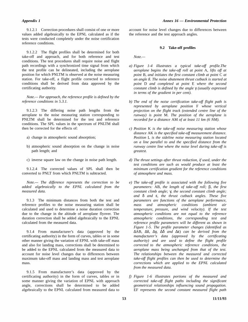
Appendix 1 Annex 16 — Environmental Protection
een
d at
is
e
ee.de
is
thehes
e
;ee,irstcedinas
gehest.
tedhed
dt
n.ath
9.1.2.1 Correction procedures shall consist of one or morevalues added algebraically to the EPNL calculated as if thetests were conducted completely under the noise certificationreference conditions.
9.1.2.2 The flight profiles shall be determined for bothtake-off and approach, and for both reference and testconditions. The test procedures shall require noise and flightpath recordings with a synchronized time signal from whichthe test profile can be delineated, including the aeroplaneposition for which PNLTM is observed at the noise measuringstation. For take-off, a flight profile corrected to referenceconditions shall be derived from data approved by thecertificating authority.
Note.— For approach, the reference profile is defined by thereference conditions in 5.3.1.
9.1.2.3 The differing noise path lengths from theaeroplane to the noise measuring station corresponding toPNLTM shall be determined for the test and referenceconditions. The SPL values in the spectrum of PNLTM shallthen be corrected for the effects of:
a) change in atmospheric sound absorption;
b) atmospheric sound absorption on the change in noisepath length; and
c) inverse square law on the change in noise path length.
9.1.2.4 The corrected values of SPL shall then beconverted to PNLT from which PNLTM is subtracted.
Note.— The difference represents the correction to beadded algebraically to the EPNL calculated from themeasured data.
9.1.3 The minimum distances from both the test andreference profiles to the noise measuring station shall becalculated and used to determine a noise duration correctiondue to the change in the altitude of aeroplane flyover. Theduration correction shall be added algebraically to the EPNLcalculated from the measured data.
9.1.4 From manufacturer’s data (approved by thecertificating authority) in the form of curves, tables or in someother manner giving the variation of EPNL with take-off massand also for landing mass, corrections shall be determined tobe added to the EPNL calculated from the measured data toaccount for noise level changes due to differences betweenmaximum take-off mass and landing mass and test aeroplanemass.
9.1.5 From manufacturer’s data (approved by thecertificating authority) in the form of curves, tables or insome manner giving the variation of EPNL with approachangle, corrections shall be determined to be addedalgebraically to the EPNL calculated from measured data to
account for noise level changes due to differences betwthe reference and the test approach angles.
9.2 Take-off profiles
Note.—
a) Figure 1-4 illustrates a typical take-off profile.Theaeroplane begins the take-off roll at point A, lifts off atpoint B, and initiates the first constant climb at point C atan angle ß. The noise abatement thrust cutback is startepoint D and completed at point E where the secondconstant climb is defined by the angle γ (usually expressedin terms of the gradient in per cent).
b) The end of the noise certification take-off flight path represented by aeroplane position F whose verticalprojection on the flight track (extended centre line of thrunway) is point M. The position of the aeroplane isrecorded for a distance AM of at least 11 km (6 NM).
c) Position K is the take-off noise measuring station whosdistance AK is the specified take-off measurement distancPosition L is the sideline noise measuring station locateon a line parallel to and the specified distance from thrunway centre line where the noise level during take-offgreatest.
d) The thrust settings after thrust reduction, if used, under test conditions are such as would produce at least tminimum certification gradient for the reference conditionof atmosphere and mass.
e) The take-off profile is associated with the following fivparameters: AB, the length of take-off roll; β, the firstconstant climb angle; γ, the second constant climb angleand δ and ε, the thrust cutback angles. These fivparameters are functions of the aeroplane performancmass and atmospheric conditions (ambient atemperature, pressure, and wind velocity). If the teatmospheric conditions are not equal to the referenatmospheric conditions, the corresponding test anreference profile parameters will be different as shown Figure 1-5. The profile parameter changes (identified ∆AB, ∆ß, ∆γ, ∆δ and ∆ε) can be derived from themanufacturer’s data (approved by the certificatinauthority) and are used to define the flight profilcorrected to the atmospheric reference conditions, taeroplane mass being unchanged from that of the teThe relationships between the measured and correctake-off flight profiles can then be used to determine tcorrections which are applied to the EPNL calculatefrom the measured data.
f) Figure 1-6 illustrates portions of the measured ancorrected take-off flight paths including the significangeometrical relationships influencing sound propagatioEF represents the second constant measured flight p
53 11/11/93
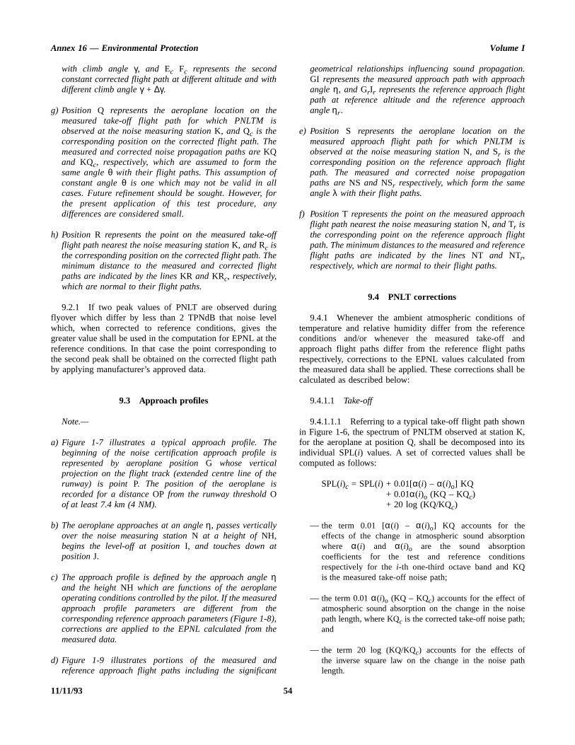
Annex 16 — Environmental Protection Volume I
n.chtch
es
hton
ch
htnce
ofcend
hsmll be
nK, itse
ion
s
ise;
ath
with climb angle γ, and Ec Fc represents the secondconstant corrected flight path at different altitude and withdifferent climb angle γ + ∆γ.
g) Position Q represents the aeroplane location on themeasured take-off flight path for which PNLTM isobserved at the noise measuring station K, and Qc is thecorresponding position on the corrected flight path. Themeasured and corrected noise propagation paths are KQand KQc, respectively, which are assumed to form thesame angle θ with their flight paths. This assumption ofconstant angle θ is one which may not be valid in allcases. Future refinement should be sought. However, forthe present application of this test procedure, anydifferences are considered small.
h) Position R represents the point on the measured take-offflight path nearest the noise measuring station K, and Rc isthe corresponding position on the corrected flight path. Theminimum distance to the measured and corrected flightpaths are indicated by the lines KR and KRc, respectively,which are normal to their flight paths.
9.2.1 If two peak values of PNLT are observed duringflyover which differ by less than 2 TPNdB that noise levelwhich, when corrected to reference conditions, gives thegreater value shall be used in the computation for EPNL at thereference conditions. In that case the point corresponding tothe second peak shall be obtained on the corrected flight pathby applying manufacturer’s approved data.
9.3 Approach profiles
Note.—
a) Figure 1-7 illustrates a typical approach profile. Thebeginning of the noise certification approach profile isrepresented by aeroplane position G whose verticalprojection on the flight track (extended centre line of therunway) is point P. The position of the aeroplane isrecorded for a distance OP from the runway threshold Oof at least 7.4 km (4 NM).
b) The aeroplane approaches at an angle η, passes verticallyover the noise measuring station N at a height of NH,begins the level-off at position I, and touches down atposition J.
c) The approach profile is defined by the approach angle ηand the height NH which are functions of the aeroplaneoperating conditions controlled by the pilot. If the measuredapproach profile parameters are different from thecorresponding reference approach parameters (Figure 1-8),corrections are applied to the EPNL calculated from themeasured data.
d) Figure 1-9 illustrates portions of the measured andreference approach flight paths including the significant
geometrical relationships influencing sound propagatioGI represents the measured approach path with approaangle η, and GrIr represents the reference approach flighpath at reference altitude and the reference approaangleηr .
e) Position S represents the aeroplane location on thmeasured approach flight path for which PNLTM iobserved at the noise measuring station N, and Sr is thecorresponding position on the reference approach fligpath. The measured and corrected noise propagatipaths are NS and NSr respectively, which form the sameangle λ with their flight paths.
f) Position T represents the point on the measured approaflight path nearest the noise measuring station N, and Tr isthe corresponding point on the reference approach fligpath. The minimum distances to the measured and refereflight paths are indicated by the lines NT and NTr,respectively, which are normal to their flight paths.
9.4 PNLT corrections
9.4.1 Whenever the ambient atmospheric conditions temperature and relative humidity differ from the referenconditions and/or whenever the measured take-off aapproach flight paths differ from the reference flight patrespectively, corrections to the EPNL values calculated frothe measured data shall be applied. These corrections shacalculated as described below:
9.4.1.1 Take-off
9.4.1.1.1 Referring to a typical take-off flight path showin Figure 1-6, the spectrum of PNLTM observed at station for the aeroplane at position Q, shall be decomposed intoindividual SPL(i) values. A set of corrected values shall bcomputed as follows:
SPL(i)c = SPL(i) + 0.01[α(i) – α(i)o] KQSPL(i)c = SPL(i) + 0.01α(i)o (KQ – KQc)SPL(i)c = SPL(i) + 20 log (KQ/KQc)
— the term 0.01 [α(i) – α(i)o] KQ accounts for theeffects of the change in atmospheric sound absorptwhere α(i) and α(i)o are the sound absorptioncoefficients for the test and reference conditionrespectively for the i-th one-third octave band and KQis the measured take-off noise path;
— the term 0.01 α(i)o (KQ – KQc) accounts for the effect ofatmospheric sound absorption on the change in the nopath length, where KQc is the corrected take-off noise pathand
— the term 20 log (KQ/KQc) accounts for the effects ofthe inverse square law on the change in the noise plength.
11/11/93 54
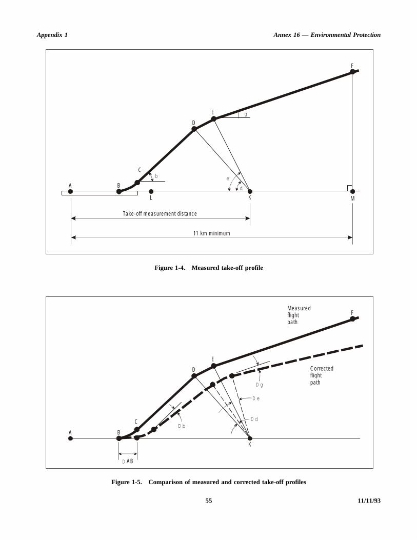
Appendix 1 Annex 16 — Environmental Protection
55 11/11/93
Figure 1-4. Measured take-off profile
Figure 1-5. Comparison of measured and corrected take-off profiles
A B
Cb
L
D
E
F
M
g
e
d
K
11 km m in im um
Take-off m easurem en t d is tanc e
A B
CD b
D
E
F
D e
D g
D d
K
D AB
C orrectedfl igh tpa th
M eas uredfl igh tpa th

Annex 16 — Environmental Protection Volume I
11/11/93 56
Figure 1-6. Take-off profile characteristics influencing sound level
Figure 1-7. Measured approach profile
E
E C
R C
R
Q
F
Q C
F C
M eas uredfl igh tpa th
C orrectedfl igh tpa th
K
g + D g
gθ
θ
Approac h m eas urem en td is tance
7 .4 km m in im um
P N O
G
H
IJ
h
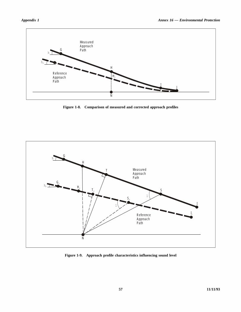
Appendix 1 Annex 16 — Environmental Protection
57 11/11/93
Figure 1-8. Comparison of measured and corrected approach profiles
Figure 1-9. Approach profile characteristics influencing sound level
M eas uredApproac hPa thG
H
H r
IJ
N
R efe renc eApproac hPa th
h
h r
M eas uredApproac hPa th
R e fe renc eApproac hPa th
G
Hh
h r
G r
H r T r
T
S
S r
l
l
I
I r
N

Annex 16 — Environmental Protection Volume I
11/11/93 58
Figure 1-10. Take-off mass correction for EPNL
Figure 1-11. Approach mass correction for EPNL
∆3
EP N L
Test M ax im um
Aerop lane take -o ff m ass
∆3
EP N L
Test M ax im um
Aerop lane land ing m as s
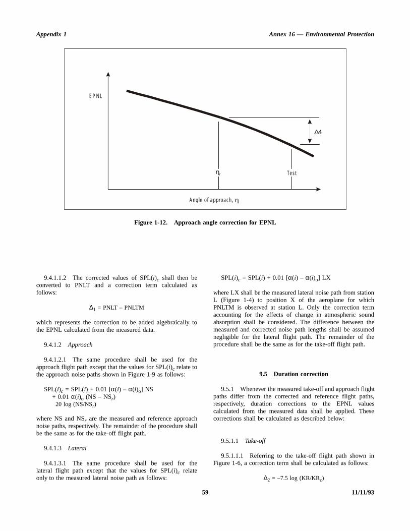
Appendix 1 Annex 16 — Environmental Protection
tionhmndthemede
ghths,esese
n:
Figure 1-12. Approach angle correction for EPNL
∆4
EP N L
Test
Ang le o f app roach , η
ηr
9.4.1.1.2 The corrected values of SPL(i)c shall then beconverted to PNLT and a correction term calculated asfollows:
∆1 = PNLT – PNLTM
which represents the correction to be added algebraically tothe EPNL calculated from the measured data.
9.4.1.2 Approach
9.4.1.2.1 The same procedure shall be used for theapproach flight path except that the values for SPL(i)c relate tothe approach noise paths shown in Figure 1-9 as follows:
SPL(i)c = SPL(i) + 0.01 [α(i) – α(i)o] NS+ 0.01 α(i)o (NS – NSr)+20 log (NS/NSr)
where NS and NSr are the measured and reference approachnoise paths, respectively. The remainder of the procedure shallbe the same as for the take-off flight path.
9.4.1.3 Lateral
9.4.1.3.1 The same procedure shall be used for thelateral flight path except that the values for SPL(i)c relateonly to the measured lateral noise path as follows:
SPL(i)c = SPL(i) + 0.01 [α(i) – α(i)o] LX
where LX shall be the measured lateral noise path from staL (Figure 1-4) to position X of the aeroplane for whicPNLTM is observed at station L. Only the correction teraccounting for the effects of change in atmospheric souabsorption shall be considered. The difference between measured and corrected noise path lengths shall be assunegligible for the lateral flight path. The remainder of thprocedure shall be the same as for the take-off flight path.
9.5 Duration correction
9.5.1 Whenever the measured take-off and approach flipaths differ from the corrected and reference flight patrespectively, duration corrections to the EPNL valucalculated from the measured data shall be applied. Thcorrections shall be calculated as described below:
9.5.1.1 Take-off
9.5.1.1.1 Referring to the take-off flight path shown iFigure 1-6, a correction term shall be calculated as follows
∆2 = –7.5 log (KR/KRc)
59 11/11/93
Annex 16 — Environmental Protection Volume I
themor-mromng
a-r’sce
thee theec-tashe
ca-ing
which represents the corrections to be added algebraically tothe EPNL calculated from the measured data. The lengths KRand KRc shall be the measured and corrected take-offminimum distances, respectively, from the noise measuringstation K to the measured and corrected flight paths. Thenegative sign shall indicate that, for the particular case of aduration correction, the EPNL calculated from the measureddata shall be reduced if the measured flight path is at a greateraltitude than the corrected flight path.
9.5.1.2 Approach
9.5.1.2.1 The same procedure shall be used for theapproach flight path except that the correction relates to theapproach minimum distances shown in Figure 1-9 as follows:
∆2 = –7.5 log (NT/NTr)
where NT is the measured approach minimum distance fromthe noise measuring station N to the measured flight path.
9.5.1.3 Lateral
9.5.1.3.1 No duration correction shall be computed for thelateral flight path because the differences between themeasured and corrected flight paths are assumed negligible.
9.6 Mass correction
9.6.1 Whenever the aeroplane mass, during either noise certification take-off or approach test, is different frothe corresponding maximum take-off or landing mass, a crection shall be applied to the EPNL value calculated frothe measured data. The corrections shall be determined fthe manufacturer’s data (approved by the certificatiauthority) in the form of tables or curves such as schemtically indicated in Figures 1-10 and 1-11. The manufacturedata shall be applicable to the noise certification referenatmospheric conditions.
9.7 Approach angle correction
9.7.1 Whenever the aeroplane approach angle during noise certification approach test is different from threference approach angle, a correction shall be applied toEPNL value calculated from the measured data. The corrtions shall be determined from the manufacturer’s da(approved by the certificating authority) in the form of tableor curves such as schematically indicated in Figure 1-12. Tmanufacturer’s data shall be applicable to the noise certifition reference atmospheric conditions and to the test landmass.
11/11/93 60
ns
ichent
entthehisentayg
heof
APPENDIX 2. EVALUATION METHOD FOR NOISE CERTIFICATION OF:
1.— SUBSONIC JET AEROPLANES—Application for Certificate of Airworthinessfor the Prototype accepted on or after6 October 1977
2.— PROPELLER-DRIVEN AEROPLANES OVER 5 700 kg—Application for Certificate of Airworthinessfor the Prototype accepted on or after1 January 1985 and before 17 November 1988
3.— PROPELLER-DRIVEN AEROPLANES OVER 8 618 kg—Application for Certificate of Airworthinessfor the Prototype accepted on or after17 November 1988
4.— HELICOPTERS
Note.— See Chapters 3 and 8, Part II.
1. INTRODUCTION
Note 1.— This noise evaluation method includes:
a) noise certification test and measurement conditions;
b) measurement of aeroplane and helicopter noise receivedon the ground;
c) calculation of effective perceived noise level frommeasured noise data; and
d) reporting of data to the certificating authority andcorrecting measured data.
Note 2.— The instructions and procedures given in themethod are clearly delineated to ensure uniformity duringcompliance tests, and to permit comparison between tests ofvarious types of aircraft conducted in various geographicallocations.
Note 3.— A complete list of symbols and units, themathematical formulation of perceived noisiness, a procedurefor determining atmospheric attenuation of sound, anddetailed procedures for correcting noise levels from
non-reference to reference conditions are included in Sectio6 to 9 of this appendix.
2. NOISE CERTIFICATION TEST ANDMEASUREMENT CONDITIONS
2.1 General
2.1.1 This section prescribes the conditions under whnoise certification shall be conducted and the measuremprocedures that shall be used.
Note.— Many applications for a noise certificate involvonly minor changes to the aircraft type design. The resultachanges in noise can often be established reliably without necessity of resorting to a complete test as outlined in tappendix. For this reason certificating authorities arencouraged to permit the use of appropriate “equivaleprocedures”. Also, there are equivalent procedures that mbe used in full certification tests, in the interest of reducincosts and providing reliable results. Guidance material on tuse of equivalent procedures in the noise certification
ANNEX 16 — VOLUME I 61 11/11/936/11/97
No. 5

Annex 16 — Environmental Protection Volume I
redot
one
torhecheed ofofnd
thes-
atlsnts
hin
d) thepththeicndm
he oftion
beof
tyichve ofich
toentg, to
subsonic jet and propeller-driven aeroplanes and helicopters isprovided in the Environmental Technical Manual on the useof Procedures in the Noise Certification of Aircraft (Doc 9501).
2.2 Test environment
2.2.1 Locations for measuring noise from an aircraft inflight shall be surrounded by relatively flat terrain having noexcessive sound absorption characteristics such as might becaused by thick, matted, or tall grass, shrubs, or wooded areas.No obstructions which significantly influence the sound fieldfrom the aircraft shall exist within a conical space above thepoint on the ground vertically below the microphone, the conebeing defined by an axis normal to the ground and by ahalf-angle 80° from this axis.
Note.— Those people carrying out the measurements couldthemselves constitute such obstructions.
2.2.2 Except as provided in 2.2.3, the tests shall be carriedout under the following atmospheric conditions:
a) no precipitation;
b) ambient air temperature not above 35°C and not below10°C and relative humidity not above 95 per cent andnot below 20 per cent over the whole noise path betweena point 10 m (33 ft) above the ground and the aircraft;
Note.— Care should be taken to ensure that the noisemeasuring, aircraft flight path tracking andmeteorological instrumentation are operated withintheir environmental limitations.
c) relative humidity and ambient temperature over thewhole noise path between a point 10 m (33 ft) above theground and the aircraft such that the sound attenuationin the one-third octave band centred on 8 kHz will notbe more than 12 dB/100 m;
d) if the atmospheric absorption coefficients vary over thePNLTM sound propagation path by more than±0.5 dB/100 m in the 3 150 Hz one-third octave bandfrom the value of the absorption coefficient derived fromthe meteorological measurement obtained at 10 m abovethe surface, ‘layered’ sections of the atmosphere must beused to compute equivalent weighted sound attenuationsin each one-third octave band, sufficient sections beingused to the satisfaction of the certificating authority;where multiple layering is not required, equivalentsound attenuations in each one-third octave band shallbe determined by averaging the atmospheric absorptioncoefficients for each such band at 10 m (33 ft) aboveground level and at the flight level of the test aircraft atthe time of PNLTM, for each measurement;
e) windspeed not above 22 km/h (12 kt) and cross-windspeed not above 13 km/h (7 kt) at 10 m (33 ft) above
ground over the 10 dB-down time interval, except fohelicopers, for which the windspeed may not exce19 km/h (10 kt) and the cross-wind speed may nexceed 9 km/h (5 kt) at 10 m (33 ft) above ground;
Note 1.— For aeroplanes, these limits are based the use of an anemometer with a built-in detector timconstant of 30 s. For anemometers with shorter detectimes the effects of short term gusts during t10 dB-down period must be considered and in suinstances the maximum value of gusts should not exc28 km/h (15 kt) and a maximum average wind valueno more than 22 km/h (12 kt). The maximum value cross-wind gust should not exceed 18 km/h (10 kt) aa maximum average cross-wind of 13 km/h (7 kt).
Note 2.— The cross-wind component is based on continuous windspeed vector resolution in the croswind direction.
f) no anomalous meteorological or wind conditions thwould significantly affect the measured noise levewhen the noise is recorded at the measuring poispecified by the certificating authority; and
g) meteorological measurements must be obtained wit30 minutes of each noise test measurement.
When a multiple layering calculation is required by 2.2.2 (the atmosphere between the aircraft and 10 m (33 ft) aboveground shall be divided into layers of equal depth. The deof the layers shall be determined by the minimum depth of layer giving a variation of ±0.5 dB/100 m in the atmospherabsorption coefficient of the 3 150 Hz one-third octave baover any part of the noise propagation path with a minimulayer depth of 30 m. The mean of the values of tatmospheric absorption coefficients at the top and bottomeach layer may be used to characterize the absorpproperties of each layer.
2.2.3 The requirements of 2.2.2 b), c) and d) shall only applied at a point 10 m (33 ft) above ground for tests helicopters.
2.2.4 The aerodrome control tower or another facilishall be approved for use as the central location at whmeasurements of atmospheric parameters are representatithose conditions existing over the geographical area in whnoise measurements are made.
2.3 Flight path measurement
2.3.1 The aircraft height and lateral position relative the flight track shall be determined by a method independof normal flight instrumentation such as radar trackintheodolite triangulation, or photographic scaling techniquesbe approved by the certificating authority.
11/11/93 624/11/99
No. 6
Appendix 2 Annex 16 — Environmental Protection
neleaste
ach
ivee.
ofacehethehenehe
ngtemoreB
ed2.6mon
nean
-d.
2.3.2 The aircraft position along the flight path shall berelated to the noise recorded at the noise measurement loca-tions by means of synchronizing signals over a distancesufficient to assure adequate data during the period that thenoise is within 10 dB of the maximum value of PNLT.
2.3.3 Position and performance data required to make theadjustments referred to in Section 8 or 9 of this appendix shallbe automatically recorded at an approved sampling rate.Measuring equipment shall be approved by the certificatingauthority.
3. MEASUREMENT OF AIRCRAFTNOISE RECEIVED ON THE GROUND
3.1 General
Note.— These measurements provided one-third octaveband levels of the noise observed at each noise-measuringstation, as a function of time, for the calculation of effectiveperceived noise level as described in Section 4.
3.1.1 The measurement system shall consist of equipmentequivalent to the following:
a) a microphone system (see 3.2);
b) a recording and reproducing system (when on-lineanalysis is not employed) to store the measured noisedata for subsequent analysis (see 3.3);
c) an analysis system to provide the output for calculationof EPNL (see 3.4);
d) calibration systems to ensure the continuous accuracy ofthe above systems (see 3.5).
3.1.2 The equipment used shall be shown by itsmanufacturers or by its users to meet the specifications of IEC561* and 651* which form the basis of 3.2, 3.3, and 3.4, or tobe of equivalent electro-acoustical performance, and shall beapproved by the certificating authority.
3.1.3 The calibration and checking procedures to be usedduring each certification test series shall be shown to meet thecorresponding specifications which are quoted in 3.5, or to beequivalent, and shall be approved by the certificating authority.
3.2 Microphone system
3.2.1 The microphone system shall consist of a micro-phone, preamplifier and wind screen meeting the specifica-tions in 3.2.2, 3.2.3, 3.2.4, 3.2.5, 3.2.6, 3.2.7 and 3.2.8. Othersystems may be approved for equivalency by the certificatingauthority on the basis of demonstrated equivalent over-all
acoustic performance. Where two or more microphosystems of the same type are used, demonstration of at one system to comply with the specifications in full will bsufficient to show type compliance.
Note.— This does not preclude the need to calibrate esystem as defined in 3.5.
3.2.2 The microphone shall be of the pressure-sensittype designed for nearly uniform grazing incidence respons
3.2.3 The microphone shall be mounted with the centrethe sensing element 1.2 m (4 ft) above the local ground surfand shall be oriented for grazing incidence, i.e. with tsensing element substantially in the plane defined by nominal flight path of the aeroplane or helicopter and tmeasuring station as shown in Figure 2-1. The microphomounting arrangement shall minimize the interference of tsupports with the sound to be measured.
3.2.4 After an adequate “warm up” period, at least as loas that specified by the equipment manufacturer, the sysoutput for constant acoustical input shall change by not mthan 0.3 dB within any one hour nor by more than 0.4 dwithin 5 hours.
3.2.5 A reference direction of incidence shall be specififor which the frequency response characteristics given in 3.apply. The change in sensitivity of the microphone systewithin angles of ±30° measured from the reference directi(see Figure 2-1) shall not exceed the following values:
Change inFrequency (Hz) sensitivity (dB)
45 to 1 120 11 120 to 2 240 1.52 240 to 4 500 2.54 500 to 7 100 47 100 to 11 200 5
3.2.6 The free-field frequency response of the microphosystem at the reference incidence direction shall lie within envelope having the following values:
Frequency ToleranceRange (Hz) (dB)
45 to 4 500 ±14 500 to 5 600 ±1.55 600 to 7 100 +1.5, –27 100 to 9 000 +1.5, –39 000 to 11 200 +2, –4
* Available from the Bureau central de la Commission électrotechnique internationale, 1 rue de Varembé, Geneva, Switzerlan
63 11/11/93

Annex 16 — Environmental Protection Volume I
asnsethe
peysis,bend
Figure 2-1. Reference direction of incidence and incidenceangle definition for grazing incidence microphones
90°G raz ing inc idencere fe renc e d irection
90°
"30°
0° 180°
Sens ing e lem en t
Note.— The requirements of this paragraph may bedetermined by a pressure response calibration (which may beobtained from an electrostatic calibrator in combination withmanufacturer provided corrections) or an anechoic free-fieldfacility.
3.2.7 With the wind screen in place, the variation insensitivity in the plane of the diaphragm of the microphonesystem shall not exceed 1.0 dB over the frequency range 45 to11 200 Hz.
3.2.8 Specifications concerning sensitivity toenvironmental factors such as temperature, relative humidity,and vibration shall be in accordance with the requirements ofIEC Publication 651.
3.2.9 Each microphone system shall be calibrated described in 3.5, and the correction for the frequency respoof the microphone system shall be reported and applied in determination of the noise level.
3.3 Recording andreproducing system
3.3.1 A recording system (such as a magnetic tarecorder) shall be used to store data for subsequent analif required. The record/replay system (including tape) shall shown to meet the specifications in 3.3.2, 3.3.3, 3.3.4 a3.3.5 at the tape speeds used for the tests.
11/11/93 64

Appendix 2 Annex 16 — Environmental Protection
the
auerest toB;dBe
bynh
be a
nd inther ofesshinr
al atl benset.5 sdB
Theibele
0.5 plusan
a
n
heale,
a
3.3.2 At standard recording level (i.e. 10 dB below the3 per cent harmonic distortion level for direct recording, or±40 per cent deviation for FM recording), in any selectedone-third octave frequency band between 180 and 11 200 Hz,the corrected frequency response shall be flat within ±0.25 dB,and in any band between 45 and 180 Hz shall be flat within±0.75 dB.
3.3.3 The amplitude fluctuations of a 1 kHz sinusoidalsignal recorded at the standard recording level shall be within±0.5 dB throughout any reel of the type of magnetic tapeutilized. Measurements to verify this shall be made using adevice with averaging properties equal to those used in themeasuring chain (see 3.4).
3.3.4 The performance of the system shall be such thatthe background noise in any one-third octave band is at least35 dB below the standard recording level (see 3.3.2).
Note.— With sharply falling spectra appropriatepre-emphasis and de-emphasis networks may need to beincluded in the system.
3.3.5 Attenuators included in the measuring chain topermit range changing shall operate in intervals of equalintegral decibel steps, and the error between any two settingsrequired for operating the equipment during noise certificationmeasurements or for associated calibrations shall not exceed0.2 dB.
3.3.6 The recording and reproducing system shall becalibrated as described in 3.5.
3.4 Analysis system
3.4.1 The output of the analysis system shall consist ofone-third octave band sound levels as a function of time,obtained by processing the (recorded) noise measurementsthrough:
a) a set of 24 one-third octave filters (or their equivalent)having geometric centre frequencies 50 Hz to 10 kHz;
b) an analyser with appropriate response and averagingproperties, in which (in principle) the output from anyone-third octave band is squared, averaged, converted tologarithmic form and digitized.
3.4.2 The one-third octave band filters shall satisfy therequirements of IEC Publication 225* and additionally haveless than 0.5 dB ripple.
The correction for effective bandwidth relative to theresponse at the frequency of the acoustic calibrator used (see3.5.5) shall be determined for the appropriate one-third octaveband filter, by measuring the filter response to sinusoidalsignals at a minimum of 20 frequencies equally spacedbetween the two adjacent preferred one-third octave
frequencies or by using equivalent procedures approved bycertificating authority.
3.4.3 The detector or detectors shall operate overminimum dynamic range of 60 dB and shall perform as trmean square devices for sinusoidal tone bursts having cfactors of up to 3 over the dynamic range extending from 030 dB below full scale reading within an accuracy of ±0.5 dthe accuracy shall be within ±1 dB between 30 and 40 below full scale reading, and within ±2.5 dB over thremaining 20 dB of range.
Compliance with this requirement shall be determined the method described in Appendix B of IEC Publicatio179A**, with the signals applied directly to the input of eacdetector in turn.
3.4.4 The averaging properties of the integrator shall tested as follows. White noise shall be passed throughone-third octave band filter with centre frequency 200 Hz astatistical bandwidth 46 ±1 Hz, and the output shall be fedturn to each detector/integrator. The standard deviation of measured levels shall be determined from a large numbesamples of the filtered white noise taken at intervals of not lthan 5 s. The value of the standard deviation shall be witthe interval 0.48 ±0.06 dB for a probability limit of 95 pecent.
3.4.5 For each detector/integrator, the response tosudden onset or interruption of a constant sinusoidal signathe respective one-third octave band centre frequency shalmeasured at sampling instants 0.5, 1, 1.5 and 2 s after the oand 0.5 and 1 s after interruption. The rising response at 0shall be –4 ±1 dB, at 1 s –1.75 ±0.75 dB, at 1.5 s –1 ±0.5 and at 2 s –0.6 ±0.5 dB relative to the steady-state level. falling response shall be such that the sum of the decreadings (below initial steady-state level) and thcorresponding rising response reading is 6.5 ±1 dB, at bothand 1 s and on subsequent records the sum of the onsetdecay must be greater than 7.5 dB. This equals to exponential averaging process (SLOW response) withnormal 1 s time constant (i.e. 2 s averaging time).
Note 1.— For analysers with linear detection aapproximation of this response would be given by:
SPL(i,k) = 10 log [0.13 (100.1L(i,k–3))
+ 0.21 (100.1L(i,k–2))
+ 0.27 (100.1L(i,k–1))
+ 0.39 (100.1L(i,k))]
* As amended. The publication was first issued in 1966 by tBureau central de la Commission électrotechnique internation1 rue de Varembé, Geneva, Switzerland.
** As amended. This publication was first issued in 1973 assupplement to IEC publication 179.
65 11/11/93

Annex 16 — Environmental Protection Volume I
unt
the or
eoisethend.3,
em is
gehall dB orhallithintheoreurech
hes oforedceo
be
heandostum
altorwnvethsnotal
histhet is
Where the weighting coefficients for simulation of slowresponse are:
Current L(i,k) ½ s record: 39 per cent
Previous L(i,k–1) ½ s record: 27 per cent
Second L(i,k–2) ½ s record: 21 per cent
Third L(i,k–3) ½ s record: 13 per cent
and where:
L(i,k), L(i,k–1), L(i,k–2) and L(i,k–3) are the as-measured ½ svalues from the analyser. These are not the weighted values ofSPL(i,k), SPL(i,k–1), SPL(i,k–2) as defined in Section 7.
It should be noted that when this approximation is used thecalibration signal should be established without thisweighting.
Note 2.– Some analysers have been shown to have signalsampling rates that are insufficiently accurate to detect signalswith crest factor ratios greater than three (common tohelicopter noise) and are therefore not considered suitable forhelicopter certification. Use of analysis systems with highsignal sampling rates (greater than 60 kHz) or those withanalog detectors prior to digitization at the output of eachone-third octave filter is encouraged.
3.4.6 Analysers using true integration cannot meet 3.4.4and 3.4.5 directly because the over-all averaging time, Ta isgreater than the sampling interval, TS (see 3.4.7). Compliancewith these clauses shall then be demonstrated in terms of theoutput of the data processor. Furthermore, in cases wherereadout and integrator resetting of the total system (includingthe data processor) require a deadtime during acquisition, thepercentage loss of the total data shall not exceed 1 per cent.When an analyser with true integration is used, this responsecan be obtained at times greater than 2.5 s from start-up, usinga continuous exponential averaging process with the followingequation:
SPL(i,k) = 10 log [(1–1/R)100.1 SPL[i,(k-1)] + (1/R)100.1 SPL(i,k)]
where SPL(i,k) is the sound pressure level at the k-th instant oftime that occurs in the i-th one-third octave and where R = 2.5for linear 0.5 s data records.
3.4.7 The sampling interval TS between successive datareadouts shall not not exceed 500 ms and its precise value shallbe known to within ±1 per cent. The instant in time by whicha readout is characterized shall be 0.75 s earlier than the actualreadout time for Ta = 2 s.
Note.— The definition of this instant in time is requiredto correlate the recorded noise with the position of the
aircraft when that noise was emitted and takes into accothe averaging period of the SLOW response.
3.4.8 In order to achieve adequate over-all precision, resolution of the digitizing system output shall be equal to,better than 0.25 dB.
3.5 Calibration and checking of system
3.5.1 Calibration and checking of the completmeasurement and analysis system used during the ncertification tests shall be carried out to the satisfaction of certificating authority at appropriate times during the tests abefore or after them, by the methods quoted in 3.5.2, 3.53.5.4, 3.5.5 and 3.5.6.
3.5.2 When on account of the use of a microphone systof known frequency response (see 3.2.5) the over-all systemcalibrated for frequency response using an insert voltatechnique, the frequency response of the electrical system sbe determined, during each test series, at a level within 10of the full-scale reading used during the tests, utilizing pinkpseudorandom noise. The output of the noise generator shave been checked by an approved standards laboratory w6 months of the test series; and tolerable changes in relative output at each one-third octave band shall be not mthan 0.2 dB. Sufficient determinations shall be made to ensthat the over-all calibration of the system is known for eatest.
Where a magnetic tape recorder forms part of tmeasuring chain, each reel of magnetic tape shall carry 30 this electrical calibration signal at its beginning and end fthis purpose. In addition, data obtained from tape-recordsignals shall be accepted as reliable only if the level differenin the 10 kHz one-third octave band filtered levels of the twsignals is not more than 0.75 dB.
3.5.3 The response of each detector/integrator shall determined in accordance with 3.4.5.
3.5.4 The performance of switched attenuators in tequipment used during noise certification measurements calibration shall be checked for each test series, using the maccurate part of the readout device to ensure that the maximerror does not exceed the resolution.
3.5.5 The response of the over-all electro-acousticsystem shall be determined using an acoustic calibragenerating a known sound pressure level at a knofrequency. The output of the acoustic calibrator shall habeen checked by a standardizing laboratory within 6 monof the test series; tolerable changes in output shall be more than 0.2 dB. A pistonphone operating at a nomin124 dB (re 20 µPa) and 250 Hz is generally used for tpurpose. Sufficient determinations shall be made during day’s work to ensure that the response of the equipmenknown for each test.
11/11/93 66
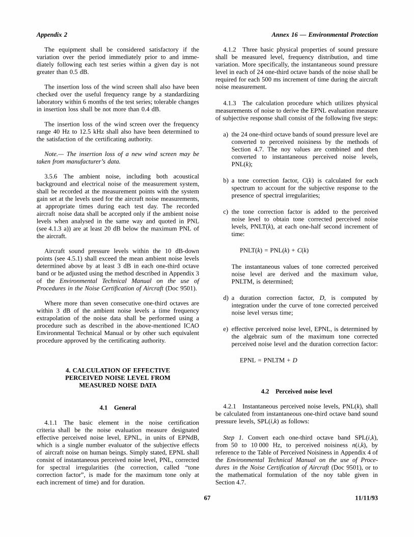
Appendix 2 Annex 16 — Environmental Protection
uree
urel beaft
alure
ps:
areofenls,
the
edisef
vede,
ed
byedor:
und
ofe-
in
The equipment shall be considered satisfactory if thevariation over the period immediately prior to and imme-diately following each test series within a given day is notgreater than 0.5 dB.
The insertion loss of the wind screen shall also have beenchecked over the useful frequency range by a standardizinglaboratory within 6 months of the test series; tolerable changesin insertion loss shall be not more than 0.4 dB.
The insertion loss of the wind screen over the frequencyrange 40 Hz to 12.5 kHz shall also have been determined tothe satisfaction of the certificating authority.
Note.— The insertion loss of a new wind screen may betaken from manufacturer’s data.
3.5.6 The ambient noise, including both acousticalbackground and electrical noise of the measurement system,shall be recorded at the measurement points with the systemgain set at the levels used for the aircraft noise measurements,at appropriate times during each test day. The recordedaircraft noise data shall be accepted only if the ambient noiselevels when analysed in the same way and quoted in PNL(see 4.1.3 a)) are at least 20 dB below the maximum PNL ofthe aircraft.
Aircraft sound pressure levels within the 10 dB-downpoints (see 4.5.1) shall exceed the mean ambient noise levelsdetermined above by at least 3 dB in each one-third octaveband or be adjusted using the method described in Appendix 3of the Environmental Technical Manual on the use ofProcedures in the Noise Certification of Aircraft (Doc 9501).
Where more than seven consecutive one-third octaves arewithin 3 dB of the ambient noise levels a time frequencyextrapolation of the noise data shall be performed using aprocedure such as described in the above-mentioned ICAOEnvironmental Technical Manual or by other such equivalentprocedure approved by the certificating authority.
4. CALCULATION OF EFFECTIVEPERCEIVED NOISE LEVEL FROM
MEASURED NOISE DATA
4.1 General
4.1.1 The basic element in the noise certificationcriteria shall be the noise evaluation measure designatedeffective perceived noise level, EPNL, in units of EPNdB,which is a single number evaluator of the subjective effectsof aircraft noise on human beings. Simply stated, EPNL shallconsist of instantaneous perceived noise level, PNL, correctedfor spectral irregularities (the correction, called “tonecorrection factor”, is made for the maximum tone only ateach increment of time) and for duration.
4.1.2 Three basic physical properties of sound pressshall be measured level, frequency distribution, and timvariation. More specifically, the instantaneous sound presslevel in each of 24 one-third octave bands of the noise shalrequired for each 500 ms increment of time during the aircrnoise measurement.
4.1.3 The calculation procedure which utilizes physicmeasurements of noise to derive the EPNL evaluation measof subjective response shall consist of the following five ste
a) the 24 one-third octave bands of sound pressure levelconverted to perceived noisiness by the methods Section 4.7. The noy values are combined and thconverted to instantaneous perceived noise levePNL(k);
b) a tone correction factor, C(k) is calculated for eachspectrum to account for the subjective response to presence of spectral irregularities;
c) the tone correction factor is added to the perceivnoise level to obtain tone corrected perceived nolevels, PNLT(k), at each one-half second increment otime:
PNLT(k) = PNL(k) + C(k)
The instantaneous values of tone corrected perceinoise level are derived and the maximum valuPNLTM, is determined;
d) a duration correction factor, D, is computed byintegration under the curve of tone corrected perceivnoise level versus time;
e) effective perceived noise level, EPNL, is determined the algebraic sum of the maximum tone correctperceived noise level and the duration correction fact
EPNL = PNLTM + D
4.2 Perceived noise level
4.2.1 Instantaneous perceived noise levels, PNL(k), shallbe calculated from instantaneous one-third octave band sopressure levels, SPL(i,k) as follows:
Step 1. Convert each one-third octave band SPL(i,k),from 50 to 10 000 Hz, to perceived noisiness n(i,k), byreference to the Table of Perceived Noisiness in Appendix 4the Environmental Technical Manual on the use of Procdures in the Noise Certification of Aircraft (Doc 9501), or tothe mathematical formulation of the noy table given Section 4.7.
67 11/11/93

Annex 16 — Environmental Protection Volume I
be
els
ewure
23hend
nd in
)s as
d
nd
Step 2. Combine the perceived noisiness values, n(i,k),found in step 1 by the following formula:
N(k) = n(k) + 0.15
N(k) = 0.85 n(k) + 0.15
where n(k) is the largest of the 24 values of n(i,k) and N(k)is the total perceived noisiness.
Step 3. Convert the total perceived noisiness, N(k), intoperceived noise level, PNL(k), by the following formula:
Note.— PNL(k) is plotted in Figure 4-1 of Appendix 4 ofDoc 9501.
4.3 Correction for spectralirregularities
4.3.1 Noise having pronounced spectral irregularities(for example, the maximum discrete frequency componentsor tones) shall be adjusted by the correction factor C(k)calculated as follows:
Step 1. Except for helicopters which start at 50 Hz (bandnumber 1), start with the corrected sound pressure level in the80 Hz one-third octave band (band number 3), calculate thechanges in sound pressure level (or “slopes”) in the remainderof the one-third octave bands as follows:
s(3,k) = no value
s(4,k) = SPL(4,k) – SPL(3,k)••s(i,k) = SPL(i,k) – SPL(i–1,k)••s(24,k) = SPL(24,k) – SPL(23,k)
Step 2. Encircle the value of the slope, s(i,k), where theabsolute value of the change in slope is greater than five; thatis, where:
| ∆s(i,k) | = | s(i,k) – s(i–1,k) | > 5
Step 3.
a) If the encircled value of the slope s(i,k), is positiveand algebraically greater than the slope s(i–1,k)encircle SPL(i,k).
b) If the encircled value of the slope s(i,k) is zero ornegative and the slope s(i–1,k) is positive, encircleSPL(i–1,k).
c) For all other cases, no sound pressure level value is toencircled.
Step 4. Compute new adjusted sound pressure levSPL′(i,k) as follows:
a) For non-encircled sound pressure levels, let the nsound pressure levels equal the original sound presslevels, SPL′(i,k) = SPL(i,k).
b) For encircled sound pressure levels in bands 1 to inclusive, let the new sound pressure level equal tarithmetic average of the preceding and following soupressure levels:
SPL′(i,k) = 2 [SPL(i–1,k) + SPL(i+1,k)]
c) If the sound pressure level in the highest frequency ba(i = 24) is encircled, let the new sound pressure levelthat band equal:
SPL′(24,k) = SPL(23,k) + s(23,k)
Step 5. Recompute new slope s′(i,k), including one for animaginary 25-th band, as follows:
s′(3,k) = s′(4,k)
s′(4,k) = SPL′(4,k) – SPL′(3,k)••s′(i,k) = SPL′(i,k) – SPL′(i–1,k)••s′(24,k) = SPL′(24,k) – SPL′(23,k)
s′(25,k) = s′(24,k)
Step 6. For i from 3 to 23 (or 1 to 23 for helicopterscompute the arithmetic average of the three adjacent slopefollows:
s(i,k) = a [s′(i,k) + s′(i+ 1,k) + s′(i+2,k)]
Step 7. Compute final one-third octave-band sounpressure levels, SPL″(i,k), by beginning with band number 3(or band number 1 for helicopters) and proceeding to banumber 24 as follows:
SPL″(3,k) = SPL(3,k)SPL″(4,k) = SPL″(3,k) + s(3,k)••SPL″(i,k) = SPL″(i–1,k) + s(i–1,k)••SPL″(24,k) = SPL″(23,k) + s(23,k)
PNL(k) = 40.0 +10
log N(k)log 2
[ n i k,( ) ] n k( )–i 1=
24
∑
n i k,( )i 1=
24
∑
11/11/93 68

Appendix 2 Annex 16 — Environmental Protection
ainade
e
or,
ismsourbyand iserth
an
esorall
ign
r
l
Step 8. Calculate the differences, F(i,k) between theoriginal sound pressure level and the final background soundpressure level as follows:
F(i,k) = SPL(i,k) – SPL″(i,k)
and note only values equal to or greater than one and a half.
Step 9. For each of the relevant one-third octave bands (3 to24), determine tone correction factors from the sound pressurelevel differences F(i,k) and Table 2-1.
Step 10. Designate the largest of the tone correction factors,determined in Step 9, as C(k). An example of the tonecorrection procedure is given in Table 4-2 of Appendix 4 ofDoc 9501.
Tone corrected perceived noise levels PNLT(k) shall bedetermined by adding the C(k) values to corresponding PNL(k)values, that is:
PNLT(k) = PNL(k) + C(k)
For any i-th one-third octave band, at any k-th increment oftime, for which the tone correction factor is suspected to resultfrom something other than (or in addition to) an actual tone (orany spectral irregularity other than aircraft noise), anadditional analysis shall be made using a filter with abandwidth narrower than one-third of an octave. If the narrowband analysis corroborates these suspicions, then a revisedvalue for the background sound pressure level SPL″(i,k), shallbe determined from the narrow band analysis and used tocompute a revised tone correction factor for that particularone-third octave band.
Note.— Other methods of rejecting spurious tonecorrections such as those described in Appendix 2 of theEnvironmental Technical Manual on the use of Procedures inthe Noise Certification of Aircraft (Doc 9501) may be used.
4.3.2 This procedure will underestimate EPNL if animportant tone is of a frequency such that it is recorded in twoadjacent one-third octave bands. It shall be demonstrated to thesatisfaction of the certificating authority:
either that this has not occurred,
or that if it has occurred that the tone correction has beenadjusted to the value it would have had if the tone hadbeen recorded fully in a single one-third octave band.
4.4 Maximum tonecorrected perceived
noise level
4.4.1 The maximum tone corrected perceived noiselevel, PNLTM, shall be the maximum calculated value of the
tone corrected perceived noise level PNLT(k). It shall becalculated in accordance with the procedure of 4.3. To obta satisfactory noise time history, measurements shall be mat 500 ms time intervals.
Note 1.— Figure 2-2 is an example of a flyover noise timhistory where the maximum value is clearly indicated.
Note 2.— In the absence of a tone correction factPNLTM would equal PNLM.
4.4.2 After the value of PNLTM is obtained, thefrequency band for the largest tone correction factor identified for the two preceding and two succeeding 500data samples. The following test shall be applied to these fsamples to identify the possibility of tone suppression one-third octave band sharing of that tone. The frequency bof the maximum tone correction factor for the four samplestested for a shift to lower frequencies (limited to threconsecutive one-third octave bands) from the first to the foudata sample. If the value of the tone correction factor C(k) forPNLTM is less than the average value of C(k) for the fiveconsecutive time intervals the average value of C(k) shall beused to compute a new value for PNLTM.
4.5 Duration correction
4.5.1 The duration correction factor D determined by theintegration technique shall be defined by the expression:
D = 10 log – PNLTM
where T is a normalizing time constant, PNLTM is themaximum value of PNLT, t1 is the first point of time afterwhich PNLT becomes greater than PNLTM – 10 and t2 is thepoint of time after which PNLT remains constantly less thPNLTM – 10.
4.5.2 Since PNLT is calculated from measured valuof SPL, there will, in general, be no obvious equation fPNLT as a function of time. Consequently, the equation shbe rewritten with a summation sign instead of an integral sas follows:
D = 10 log – PNLTM
where ∆t is the length of the equal increments of time fowhich PNLT(k) is calculated and d is the time interval to thenearest 1.0 s during which PNLT(k) remains greater or equato PNLTM – 10.
1T---
antiPNLT
10----------------log td
t1
t2
∫
1T---
t antiPNLT k( )
10-----------------------log⋅∆
k 0=
d t∆⁄
∑
69 11/11/93
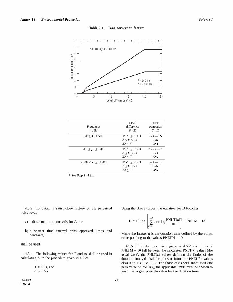
Annex 16 — Environmental Protection Volume I
s
f
neo
Table 2-1. Tone correction factors
Frequency/, Hz
Leveldifference
F, dB
Tonecorrection
C, dB
50 < / < 500 12* < F < 33 < F < 2020 < F
F/3 — 2F/63a
500 < / < 5 000 12* < F < 33 < F < 2020 < F
2 F/3 — 1F/36b
5 000 < / < 10 000 12* < F < 33 < F < 2020 < F
F/3 — 2F/63a
* See Step 8, 4.3.1.
00
1
2
3
4
5
6
7
8
5 1 0 1 5 2 0 2 5
5 0 0 H z 5 0 0 0 H zf≤ ≤
ff < 5 0 0 H z > 5 00 0 H z
L e ve l d iffe re n c e , d BF
Tone
cor
rect
ion
, dB
C
4.5.3 To obtain a satisfactory history of the perceivednoise level,
a) half-second time intervals for ∆t, or
b) a shorter time interval with approved limits andconstants,
shall be used.
4.5.4 The following values for T and ∆t shall be used incalculating D in the procedure given in 4.5.2:
T = 10 s, and∆t = 0.5 s
Using the above values, the equation for D becomes
D = 10 log – PNLTM – 13
where the integer d is the duration time defined by the pointcorresponding to the values PNLTM – 10.
4.5.5 If in the procedures given in 4.5.2, the limits oPNLTM – 10 fall between the calculated PNLT(k) values (theusual case), the PNLT(k) values defining the limits of theduration interval shall be chosen from the PNLT(k) valuesclosest to PNLTM – 10. For those cases with more than opeak value of PNLT(k), the applicable limits must be chosen tyield the largest possible value for the duration time.
antiPNLT k( )
10-----------------------log
k 0=
2d
∑
11/11/93 704/11/99
No. 6
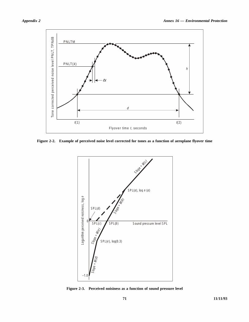
Appendix 2 Annex 16 — Environmental Protection
71 11/11/93
Figure 2-2. Example of perceived noise level corrected for tones as a function of aeroplane flyover time
Figure 2-3. Perceived noisiness as a function of sound pressure level
∆t
h
d
P N LT M
P N LT ( )k
t(1) t(2)
F lyove r tim e , seco n d st
Tone
cor
rect
ed p
erce
ived
noi
se le
vel P
NLT
, T
PN
dB
S lo pe = M(c)
SP L( ), lo g ( )a n a
SP L( )d
S lope
= M
(b)
SP L( )c SP L( )b
S lop
e =
M(e
)
SP L( ), lo g (0 .3 )e
S lop
e =
M( d
)
–1.0
Loga
rithm
per
ceiv
ed n
oisi
ness
, log
n
0Soun d p ressure le ve l S PL

Annex 16 — Environmental Protection Volume I
gfor
ofbe
hallithn 3
ndata
a, thedix
ndbe
ft,
nd
vity
ng);
e
er
4.6 Effective perceived noise level
4.6.1 The total subjective effect of an aircraft noiseevent, designated effective perceived noise level, EPNL, shallbe equal to the algebraic sum of the maximum value of thetone corrected perceived noise level, PNLTM, and theduration correction D. That is:
EPNL = PNLTM + D
where PNLTM and D are calculated in accordance with theprocedures given in 4.2, 4.3, 4.4 and 4.5.
4.7 Mathematical formulationof noy tables
4.7.1 The relationship between sound pressure level(SPL) and the logarithm of perceived noisiness is illustrated inTable 2-2 and Figure 2-3.
4.7.2 The important aspects of the mathematicalformulation are:
a) the slopes (M(b), M(c), M(d) and M(e)) of the straightlines;
b) the intercepts (SPL(b) and SPL(c)) of the lines on theSPL axis; and
c) the coordinates of the discontinuities, SPL(a) andlog n(a); SPL(d) and log n = –1.0; and SPL(e) and logn = log (0.3).
4.7.3 The equations are as follows:
a) SPL > SPL(a)n = antilog {M(c) [SPL – SPL(c)]}
b) SPL(b) < SPL < SPL(a)n = antilog {M(b) [SPL – SPL(b)]}
c) SPL(e) < SPL < SPL(b)n = 0.3 antilog10 {M(e) [SPL – SPL(e)]}
d) SPL(d) < SPL < SPL(e)n = 0.1 antilog {M(d) [SPL – SPL(d)]}
4.7.4 Table 2-2 lists the values of the constants necessaryto calculate perceived noisiness as a function of sound pressurelevel.
5. REPORTING OF DATA TO THECERTIFICATING AUTHORITY
5.1 General
5.1.1 Data representing physical measurements orcorrections to measured data shall be recorded in permanentform and appended to the record.
5.1.2 All corrections shall be approved by certificatinauthority. In particular the corrections to measurements equipment response deviations shall be reported.
5.1.3 Estimates of the individual errors inherent in eachthe operations employed in obtaining the final data shall reported, if required.
5.2 Data reporting
5.2.1 Measured and corrected sound pressure levels sbe presented in one-third octave band levels obtained wequipment conforming to the Standards described in Sectioof this appendix.
5.2.2 The type of equipment used for measurement aanalysis of all acoustic performance and meteorological dshall be reported.
5.2.3 The following atmospheric environmental datmeasured immediately before, after, or during each test atobservation points prescribed in Section 2 of this appenshall be reported:
a) air temperature and relative humidity;
b) maximum, minimum and average wind velocities; and
c) atmospheric pressure.
5.2.4 Comments on local topography, ground cover, aevents that might interfere with sound recordings shall reported.
5.2.5 The following information shall be reported:
a) type, model and serial numbers (if any) of aircraengines, propellers, or rotors (as applicable);
b) gross dimensions of aircraft and location of engines arotors (if applicable);
c) aircraft gross mass for each test run and centre of grarange for each series of test runs;
d) aircraft configuration such as flap, airbrakes and landigear positions and propeller pitch angles (if applicable
e) whether auxiliary power units (APU), when fitted, aroperating;
f) conditions of pneumatic engine bleeds and engine powtake-offs;
g) indicated airspeed in kilometres per hour (knots);
11/11/93 72
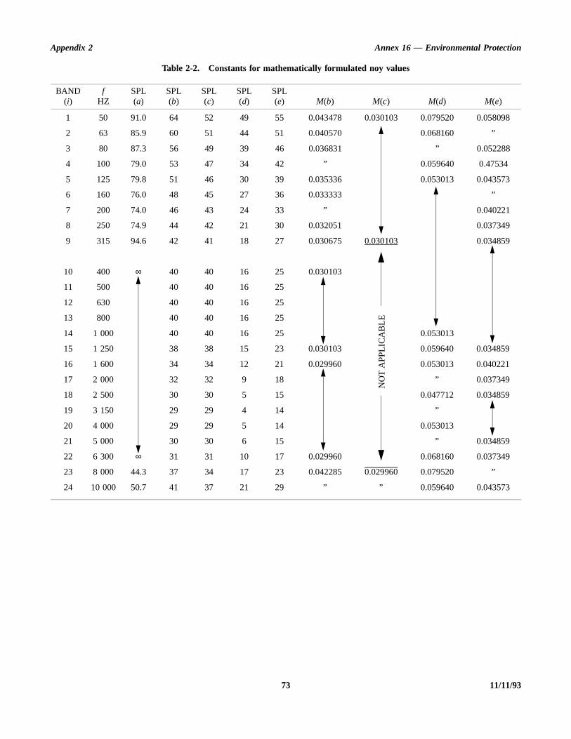
Appendix 2 Annex 16 — Environmental Protection
73 11/11/93
Table 2-2. Constants for mathematically formulated noy values
BAND(i)
fHZ
SPL(a)
SPL(b)
SPL(c)
SPL(d)
SPL(e) M(b) M(c) M(d) M(e)
1 50 91.0 64 52 49 55 0.043478 0.030103 0.079520 0.058098
2 63 85.9 60 51 44 51 0.040570 0.068160 ”
3 80 87.3 56 49 39 46 0.036831 ” 0.052288
4 100 79.0 53 47 34 42 ” 0.059640 0.47534
5 125 79.8 51 46 30 39 0.035336 0.053013 0.043573
6 160 76.0 48 45 27 36 0.033333 ”
7 200 74.0 46 43 24 33 ” 0.040221
8 250 74.9 44 42 21 30 0.032051 0.037349
9 315 94.6 42 41 18 27 0.030675 0.030103 0.034859
10 400 ∞ 40 40 16 25 0.030103
11 500 40 40 16 25
12 630 40 40 16 25
13 800 40 40 16 25
14 1 000 40 40 16 25 0.053013
15 1 250 38 38 15 23 0.030103 0.059640 0.034859
16 1 600 34 34 12 21 0.029960 0.053013 0.040221
17 2 000 32 32 9 18 ” 0.037349
18 2 500 30 30 5 15 0.047712 0.034859
19 3 150 29 29 4 14 ”
20 4 000 29 29 5 14 0.053013
21 5 000 30 30 6 15 ” 0.034859
22 6 300 ∞ 31 31 10 17 0.029960 0.068160 0.037349
23 8 000 44.3 37 34 17 23 0.042285 0.029960 0.079520 ”
24 10 000 50.7 41 37 21 29 ” ” 0.059640 0.043573
NO
T A
PP
LIC
AB
LE

Annex 16 — Environmental Protection Volume I
alidoff,. If anytestters,bel be
seint;
chrper
of forheachentultise
ce
ise
eiseoise
l
mits
the
h) 1) for jet aeroplanes: engine performance in terms ofnet thrust, engine pressure ratios, jet exhausttemperatures and fan or compressor shaft rotationalspeeds as determined from aeroplane instruments andmanufacturer’s data;
2) for propeller-driven aeroplanes: engine performancein terms of brake horsepower and residual thrust orequivalent shaft horsepower or engine torque andpropeller rotational speed as determined fromaeroplane instruments and manufacturer’s data;
3) for helicopters: engine performance and rotor speedin rpm during each demonstration;
i) aircraft flight path and ground speed during eachdemonstration; and
j) any modifications or non-standard equipment likely toaffect the noise characteristics of the aircraft.
5.3 Reporting of noise certificationreference conditions
5.3.1 Aircraft position and performance data and thenoise measurements shall be corrected to the noisecertification reference conditions as specified in the relevantchapter of Part II, and these conditions, including referenceparameters, procedures and configurations shall be reported.
5.4 Validity of results
5.4.1 Three average reference EPNL values and their90 per cent confidence limits shall be produced from the testresults and reported, each such value being the arithmetical
average of the adjusted acoustical measurements for all vtest runs at the appropriate measurement point (take-approach, or lateral or overflight, in the case of helicopters)more than one acoustic measurement system is used atsingle measurement location, the resulting data for each run shall be averaged as a single measurement. For helicopthe three microphone test results for each flight should averaged as a single measurement. The calculation shalperformed by:
a) computing the arithmetic average for each flight phausing the values from each reference microphone po
b) computing the over-all arithmetic average for eaappropriate reference condition (take-off, overflight, oapproach) using the values in a) and the related 90 cent confidence limits.
5.4.2 The minimum sample size acceptable for eachthe three certification measuring points for aeroplanes andeach set of three microphones for helicopters is six. Tsamples shall be large enough to establish statistically for eof the three average noise certification levels a 90 per cconfidence limit not exceeding ±1.5 EPNdB. No test resshall be omitted from the averaging process unless otherwspecified by the certificating authority.
Note.— Methods for calculating the 90 per cent confideninterval are given in Appendix 1 of the EnvironmentalTechnical Manual on the use of Procedures in the NoCertification of Aircraft (Doc 9501).
5.4.3 The average EPNL figures obtained by thforegoing process shall be those by which the noperformance of the aircraft is assessed against the ncertification criteria.
6. NOMENCLATURE: SYMBOLS AND UNITS
Symbol Unit Meaning
antilog — Antilogarithm to the base 10.
C(k) dB Tone correction factor. The factor to be added to PNL(k) to account for the presence of spectrairregularities such as tones at the k-th increment of time.
d s Duration time. The length of the significant noise time history being the time interval between the liof t(1) and t(2) to the nearest second.
D dB Duration correction. The factor to be added to PNLTM to account for the duration of the noise.
EPNL EPNdB Effective perceived noise level. The value of PNL adjusted for both the spectral irregularities and duration of the noise. (The unit EPNdB is used instead of the unit dB.)
11/11/93 74

Appendix 2 Annex 16 — Environmental Protection
sound
ands
that
ing
with
ency
tead
cur
t
ssure
Symbol Unit Meaning
f(i) Hz Frequency. The geometrical mean frequency for the i-th one-third octave band.
F(i,k) dB Delta-dB. The difference between the original sound pressure level and the final background pressure level in the i-th one-third octave band at the k-th interval of time.
h dB dB-down. The level to be subtracted from PNLTM that defines the duration of the noise.
H % Relative humidity. The ambient atmospheric relative humidity.
i — Frequency band index. The numerical indicator that denotes any one of the 24 one-third octave bwith geometrical mean frequencies from 50 to 10 000 Hz.
k — Time increment index. The numerical indicator that denotes the number of equal time incrementshave elapsed from a reference zero.
log — Logarithm to the base 10.
log n(a) — Noy discontinuity co-ordinate. The log n value of the intersection point of the straight lines representthe variation of SPL with log n.
M(b), M(c), etc. — Noy inverse slope. The reciprocals of the slopes of straight lines representing the variation of SPL log n.
n noy Perceived noisiness. The perceived noisiness at any instant of time that occurs in a specified frequrange.
n(i,k) noy Perceived noisiness. The perceived noisiness at the k-th instant of time that occurs in the i-th one-thirdoctave band.
n(k) noy Maximum perceived noisiness. The maximum value of all of the 24 values of n(i) that occurs at the k-thinstant of time.
N(k) noy Total perceived noisiness. The total perceived noisiness at the k-th instant of time calculated from the24-instantaneous values of n(i,k).
p(b), p(c), etc. — Noy slope. The slopes of straight lines representing the variation of SPL with log n.
PNL PNdB Perceived noise level. The perceived noise level at any instant of time. (The unit PNdB is used insof the unit dB.)
PNL(k) PNdB Perceived noise level. The perceived noise level calculated from the 24 values of SPL(i,k) at the k-thincrement of time. (The unit PNdB is used instead of the unit dB.)
PNLM PNdB Maximum perceived noise level. The maximum value of PNL(k). (The unit PNdB is used instead of theunit dB.)
PNLT TPNdB Tone corrected perceived noise level. The value of PNL adjusted for the spectral irregularities that ocat any instant of time. (The unit TPNdB is used instead of the unit dB.)
PNLT(k) TPNdB Tone corrected perceived noise level. The value of PNL(k) adjusted for the spectral irregularities thaoccur at the k-th increment of time. (The unit TPNdB is used instead of the unit dB.)
PNLTM TPNdB Maximum tone corrected perceived noise level. The maximum value of PNLT(k). (The unit TPNdB isused instead of the unit dB.)
PNLTr TPNdB Tone corrected perceived noise level adjusted for reference conditions.
s(i,k) dB Slope of sound pressure level. The change in level between adjacent one-third octave band sound prelevels at the i-th band for the k-th instant of time.
75 11/11/93

Annex 16 — Environmental Protection Volume I
tave
for
ency
ting
with
nd
tion
Symbol Unit Meaning
∆s(i,k) dB Change in slope of sound pressure level.
s′(i,k) dB Adjusted slope of sound pressure level. The change in level between adjacent adjusted one-third ocband sound pressure levels at the i-th band for the k-th instant of time.
s(i,k) dB Average slope of sound pressure level.
t s Elapsed time. The length of time measured from a reference zero.
t1, t2 s Time limit. The beginning and end, respectively, of the significant noise time history defined by h.
∆t s Time increment. The equal increments of time for which PNL(k) and PNLT(k) are calculated.
T s Normalizing time constant. The length of time used as a reference in the integration methodcomputing duration corrections, where T = 10 s.
t (°C) °C Temperature. The ambient atmospheric temperature.
α(i) dB/100 m Test atmospheric absorption. The atmospheric attenuation of sound that occurs in the i-th one-thirdoctave band for the measured atmospheric temperature and relative humidity.
α(i)O dB/100 m Reference atmospheric absorption. The atmospheric attenuation of sound that occurs in the i-th one-thirdoctave band for a reference atmospheric temperature and relative humidity.
A1 degrees First constant* climb angle.
A2 degrees Second constant** climb angle.
η degrees Approach angle.
* Gear up, speed of at least V2 + 19 km/h (V2 + 10 kt), take-off thrust.** Gear up, speed of at least V2 + 19 km/h (V2 + 10 kt), after cut-back.
SPL dB re20µPa
Sound pressure level. The sound pressure level at any instant of time that occurs in a specified frequrange.
SPL(a) dB re20 µPa
Noy discontinuity co-ordinate. The SPL value of the intersection point of the straight lines representhe variation of SPL with log n.
SPL(b)SPL(c)
dB re20 µPa
Noy intercept. The intercepts on the SPL-axis of the straight lines representing the variation of SPLlog n.
SPL(i,k) dB re20 µPa
Sound pressure level. The sound pressure level at the k-th instant of time that occurs in the i-th one-thirdoctave band.
SPL′(i,k) dB re20 µPa
Adjusted sound pressure level. The first approximation to background sound pressure level in the i-thone-third octave band for the k-th instant of time.
SPL(i) dB re20 µPa
Maximum sound pressure level. The sound pressure level that occurs in the i-th one-third octave band ofthe spectrum for PNLTM.
SPL(i)r dB re20 µPa
Corrected maximum sound pressure level. The sound pressure level that occurs in the i-th one-third octaveband of the spectrum for PNLTM corrected for atmospheric sound absorption.
SPL″(i,k) dB re20 µPa
Final background sound pressure level. The second and final approximation to background soupressure level in the i-th one-third octave band for the k-th instant of time.
δε
degreesdegrees
Thrust cutback angles. The angles defining the points on the take-off flight path at which thrust reducis started and ended respectively.
11/11/93 76

Appendix 2 Annex 16 — Environmental Protection
for
for
nt forference
rednditions.
ta to
iseest beeenfor
t
ise.5.
befer-
by
nde
Symbol Unit Meaning
ηr degrees Reference approach angle.
θ degrees Noise angle (relative to flight path). The angle between the flight path and noise path. It is identical both measured and corrected flight paths.
ψ degrees Noise angle (relative to ground). The angle between the noise paths and the grounds. It is identifiedboth measured and corrected flight paths.
µ degrees Engine noise emission parameter. (See 9.3.4.)
∆1 EPNdB PNLT correction. The correction to be added to the EPNL calculated from measured data to accounoise level changes due to differences in atmospheric absorption and noise path length between reand test conditions.
∆2 EPNdB Adjustment to duration correction. The adjustment to be made to the EPNL calculated from measudata to account for noise level changes due to the noise duration between reference and test co
∆3 EPNdB Source noise adjustment. The adjustment to be made to the EPNL calculated from measured daaccount for noise level changes due to differences between reference and test engine regime.
7. SOUND ATTENUATIONIN AIR
7.1 The atmospheric attenuation of sound shall bedetermined in accordance with the procedure presented below.
7.2 The relationship between sound attenuation,frequency, temperature and humidity is expressed by thefollowing equations:
α(i) = 10[2.05 log (fo/1000) + 1.1394 × 10⁻³ θ – 1.916984]
+ η(δ) × 10[log (fo) + 8.42994 × 10⁻³ θ – 2.755624]
10(log H – 1.328924 + 3.179768 × 10⁻²θ)
× 10(–2.173716 × 10⁻⁴θ2 + 1.7496 × 10⁻⁶θ3)
where:
η(δ) is given by Table 2-3 and fo by Table 2-4;
α(i) being the attenuation coefficient in dB/100 m;
θ being the temperature in °C; and
H being the relative humidity expressed as a percentage.
7.3 The equations given in 7.2 are convenient forcalculation by means of a computer.
8. ADJUSTMENT OFHELICOPTER FLIGHT
TEST RESULTS
8.1 General
8.1.1 Adjustments shall be made to the measured nodata by the methods of this section. Compliance with the tconditions of Chapter 8, 8.7.5 is necessary for the test toacceptable. Adjustments shall be made for differences betwtest and reference flight procedures and shall account differences in the following:
a) helicopter flight path and velocity relative to the flighpath reference point;
b) sound attenuation in air;
c) in the overflight case, parameters affecting the nogenerating mechanisms such as those described in 8
8.1.2 Adjustments to the measured noise data shall made using the methods prescribed in 8.3 and 8.4, for difences in the following:
a) attenuation of the noise along its path as affected “inverse square” and atmospheric attenuation;
b) duration of the noise as affected by distance aspeed of aircraft relative to the flight path referencpoint;
δ 1010fo
------------=
77 11/11/93

Annex 16 — Environmental Protection Volume I
11/11/93 78
Table 2.3 Values of η(δ)
Table 2-4. Value of fo
δ η(δ) δ η(δ)
0.00 0.000 2.50 0.450
0.25 0.315 2.80 0.400
0.50 0.700 3.00 0.370
0.60 0.840 3.30 0.330
0.70 0.930 3.60 0.300
0.80 0.975 4.15 0.260
0.90 0.996 4.45 0.245
1.00 1.000 4.80 0.230
1.10 0.970 5.25 0.220
1.20 0.900 5.70 0.210
1.30 0.840 6.05 0.205
1.50 0.750 6.50 0.200
1.70 0.670 7.00 0.200
2.00 0.570 10.00 0.200
2.30 0.495
A term of quadratic interpolation shall be used where necessary.
Centre frequencyof the 1/3
octave band(Hz)
fo(Hz)
Centre frequencyof the 1/3
octave band(Hz)
fo(Hz)
50 50 800 800
63 63 1 000 1 000
80 80 1 250 1 250
100 100 1 600 1 600
125 125 2 000 2 000
160 160 2 500 2 500
200 200 3 150 3 150
250 250 4 000 4 000
315 315 5 000 4 500
400 400 6 300 5 600
500 500 8 000 7 100
630 630 10 000 9 000

Appendix 2 Annex 16 — Environmental Protection
e
esht
ith.
te
once
ith.
d
t.
toht
ith.
c) the adjustment procedure described in this sectionshall apply to the lateral microphones in the take-off,overflight and approach cases. Although the noiseemission is strongly dependent on the directivity pattern,variable from one helicopter type to another, thepropagation angle I, defined in Appendix 2, 9.3.2,Figure 2-11, shall be the same for the test and referenceflight paths. The elevation angle ψ shall not beconstrained as in the third note of Appendix 2, 9.3.2, butmust be determined and reported. The certificationauthority shall specify the acceptable limitations on ψ.Corrections to data obtained when these limits areexceeded shall be applied using procedures approved bythe certificating authority. In the particular case of lateralnoise measurement, sound propagation is affected notonly by “inverse square” and atmospheric attenuation,but also by ground absorption and reflection effectswhich depend mainly on the angleψ.
Note 1.— Chapter 8, 8.7.5 in Part II of this volume placeslimits on the maximum adjustments that may be made betweentest and reference flight procedures and conditions.
Note 2.— Adjustments of noise levels for test to referenceconditions may be made, subject to agreement by thecertificating authority, by the methods of this section. Thecorrections are derived from sets of curves linking the instantat which the PNLTM is emitted for each reference procedurewith appropriate parameters. The sensitivity curves providenoise level variations as a function of the parameter for whicha correction is necessary.
8.2 Flight profiles
Note.— Flight profiles for the test conditions are describedby their geometry relative to the ground, together with theassociated helicopter speed.
8.2.1 Take-off profile
Note 1.— Figure 2-4 illustrates typical test and referenceprofiles.
a) During actual testing the helicopter is initiallystabilized in level flight at the best rate of climb speed,Vy, at a point A and continues to a point Bwhere take-off power is applied and a steady climb isinitiated. A steady climb shall be maintainedthroughout the 10 dB-down period and beyond to theend of the certification flight path (point F).
b) Position K1 is the take-off flight path reference pointand NK1 is the distance from the initiation of the
steady climb to the take-off flight path referencpoint. Positions K1′ and K1″ are associated noisemeasurement points located on a line at right anglto and at the specified distance from the take-off fligtrack TM.
c) The distance TM is the distance over which thehelicopter position is measured and synchronized wthe noise measurements (see 2.3.2 of this appendix)
Note 2.— The position of point B may vary within thelimits allowed by the certificating authority.
8.2.2 Overflight profile
Note.— Figure 2-5 illustrates a typical overflight profile.
a) The helicopter is stabilized in level flight at point D andflies through point W, overhead the flight path referencepoint, to point E, the end of the noise certificationoverflight flight path.
b) Position K2 is the overflight flight path reference poinand K2W is the height of the helicopter overhead thoverflight flight path reference point. Positions K2′ andK2″ are associated noise measurement points locateda line at right angles to and at the specified distanfrom the overflight flight track RS.
c) The distance RS is the distance over which thehelicopter position is measured and synchronized wthe noise measurements (see 2.3.2 of this appendix)
8.2.3 Approach profile
Note.— Figure 2-6 illustrates a typical approach profile.
a) The helicopter is initially stabilized at the specifieapproach path angle at point G and continues throughpoint H, point I and then to touchdown.
b) Position K3 is the approach flight path referencepoint and K3H is the height of the helicopteroverhead the approach flight path reference poinPositions K3′ and K3″ are associated noisemeasurement locations on a line at right angles and at the specified distance from the approach fligpath track PU.
c) The distance PU is the distance over which thehelicopter position is measured and synchronized wthe noise measurements (see 2.3.2 of this appendix)
79 11/11/936/11/97
No. 5
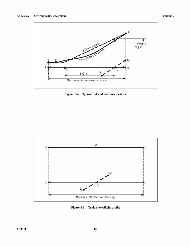
Annex 16 — Environmental Protection Volume I
11/11/93 80
Figure 2-4. Typical test and reference profiles
Figure 2-5. Typical overflight profile
T
A B
N
500 m
M eas urem en ts m ade ove r th is range
K ’1
K ”1
K 1M
F
R efe renc ehe igh t
R efere nce p rofile
An actual ta k e -o f f p r o file
WD E
SR
M eas urem en ts m ade ove r th is range
K ’2
K ”2
K 2
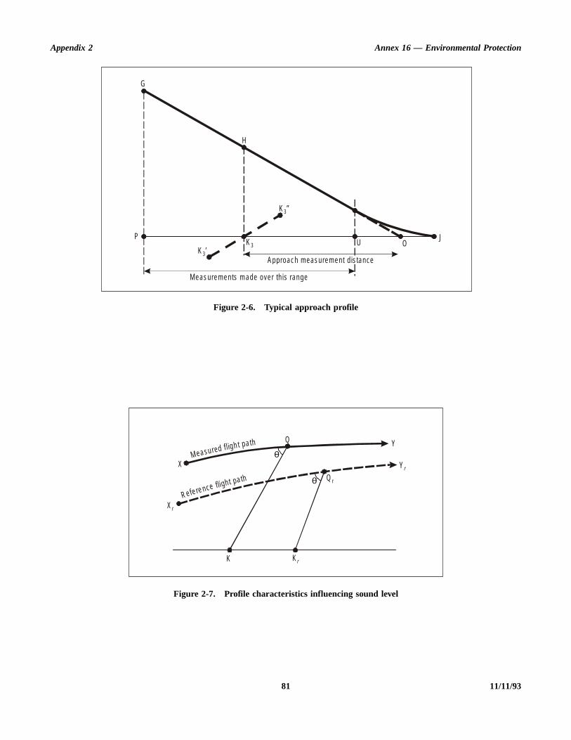
Appendix 2 Annex 16 — Environmental Protection
81 11/11/93
Figure 2-6. Typical approach profile
Figure 2-7. Profile characteristics influencing sound level
Approac h m eas urem en t d is tance
M eas urem en ts m ade ove r th is range
OJ
UK ’3
K ”3
K 3P
H
G
M ea su red f l igh t pa th
Refe re nce fligh t pa th
X
X r
Q Y
Y r
Q r
θ
θ
K K r

Annex 16 — Environmental Protection Volume I
L
Treeakach
. Ifthethera.
theehe tohe
e
y to
alueen
omity.ityr;
tiveing
uecee aby
8.3 Adjustments of PNL and PNLT
Note.— The portions of the test flight path and referenceflight path which are significant for the EPNL calculation areillustrated in Figure 2-7 for take-off, overflight and approachmeasurements.
a) XY represents the useful portion of the measured flightpath and XrYr that of the corresponding reference flightpath.
b) Q represents the helicopter position on the measuredflight path at which the noise was emitted and observedas PNLTM at the noise measuring point K. Qr is thecorresponding position on the reference flight path andKr the reference noise measuring point. QK and QrKrare respectively the measured and reference noisepropagation paths, Qr being located on the assumptionthat QK and QrKr form the same angle I with theirrespective flight paths.
8.3.1 The one-third octave band levels SPL(i) comprisingPNL (the PNL at the moment of PNLTM observed at K) shallbe adjusted to reference levels SPL(i)r as follows:
SPL(i)r = SPL(i) + 0.01 [α(i) – α(i)o] QK
+ 0.01 α(i)o (QK – QrKr)
+ 20 log (QK/QrKr)
In this expression:
— the term 0.01 [α(i) – α(i)o] QK accounts for the effectof the change in sound attenuation coefficient and α(i)and α(i)o are the coefficients for the test and referenceatmospheric conditions respectively, obtained fromSection 7 of this Appendix;
— the term 0.01 α(i)o (QK – QrKr) accounts for the effectof the change in the noise path length on the soundattenuation;
— the term 20 log (QK/QrKr) accounts for the effect of thechange in the noise path length due to the “inversesquare” law;
— QK and QrKr are measured in metres and α(i) and α(i)oare in dB/100 m.
Note.— When SPL(i) is zero (for example as a result ofapplying background noise corrections) SPL(i)r must also bekept equal to zero in the adjustment process.
8.3.2 The corrected values SPL(i)r shall be converted toPNLTr and a correction term calculated as follows:
∆1 = PNLTr – PNLTM
8.3.3 ∆1 shall be added algebraically to the EPNcalculated from the measured data.
8.3.4 If, during a test flight, several peak values of PNLare observed which are within 2 dB of PNLTM, the procedudefined in 8.3.1, 8.3.2 and 8.3.3 shall be applied at each pand the adjustment term so calculated shall be added to epeak to give corresponding adjusted peak values of PNLTthese peak values exceed that at the moment of PNLTM, maximum value of such excess shall be added as a furadjustment to the EPNL calculated from the measured dat
8.4 Adjustments ofduration correction
8.4.1 Whenever the measured flight paths and/or ground velocities in the test conditions differ from threference flight paths and/or the ground velocities in treference conditions, duration adjustments shall be appliedthe EPNL values calculated from the measured data. Tadjustments shall be calculated as described below.
8.4.2 Referring to the flight path shown in Figure 2-7, thadjustment term shall be calculated as follows:
∆2 = –7.5 log (QK/QrKr) + 10 log (V/Vr)
which represents the adjustment to be added algebraicallthe EPNL calculated from the measured data.
8.5 Correction of noiseat source
For overflight, if any combination of the following threefactors:
a) airspeed deviations from reference;
b) rotor speed deviations from reference;
c) temperature deviations from reference;
results in an agreed noise correlating parameter whose vdeviates from the reference value of this parameter, thsource noise adjustments shall be determined frmanufacturer’s data approved by the certificating authorThis correction should normally be made using a sensitivcurve of PNLTM versus advancing blade tip Mach numbehowever, the correction may be made using an alternaparameter, or parameters, approved by the certificatauthority.
Note 1.— If it is not possible to attain the reference valof advancing blade tip Mach number or the agreed referennoise correlating parameter then an extrapolation of thsensitivity curve is permitted providing that the data coverrange of values of the noise correlating parameter agreed
11/11/93 82
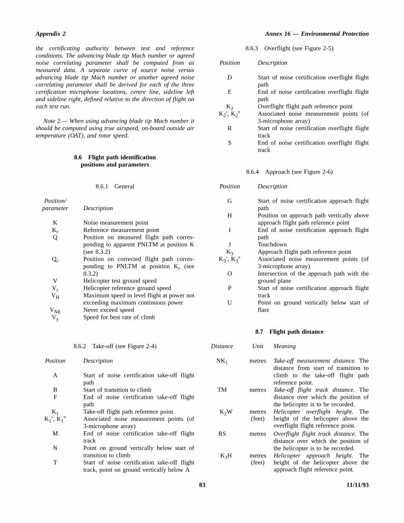
Appendix 2 Annex 16 — Environmental Protection
of
t
e
of
e
t
f
f
f
the certificating authority between test and referenceconditions. The advancing blade tip Mach number or agreednoise correlating parameter shall be computed from asmeasured data. A separate curve of source noise versusadvancing blade tip Mach number or another agreed noisecorrelating parameter shall be derived for each of the threecertification microphone locations, centre line, sideline leftand sideline right, defined relative to the direction of flight oneach test run.
Note 2.— When using advancing blade tip Mach number itshould be computed using true airspeed, on-board outside airtemperature (OAT), and rotor speed.
8.6 Flight path identificationpositions and parameters
8.6.1 General
Position/parameter Description
K Noise measurement pointKr Reference measurement pointQ Position on measured flight path corres-
ponding to apparent PNLTM at position K(see 8.3.2)
Qr Position on corrected flight path corres-ponding to PNLTM at position Kr (see8.3.2)
V Helicopter test ground speedVr Helicopter reference ground speedVH Maximum speed in level flight at power not
exceeding maximum continuous powerVNE Never exceed speedVy Speed for best rate of climb
8.6.2 Take-off (see Figure 2-4)
Position Description
A Start of noise certification take-off flightpath
B Start of transition to climbF End of noise certification take-off flight
pathK1 Take-off flight path reference point
K1′, K1″ Associated noise measurement points (of3-microphone array)
M End of noise certification take-off flighttrack
N Point on ground vertically below start oftransition to climb
T Start of noise certification take-off flighttrack, point on ground vertically below A
8.6.3 Overflight (see Figure 2-5)
Position Description
D Start of noise certification overflight flightpath
E End of noise certification overflight flightpath
K2 Overflight flight path reference pointK2′, K2″ Associated noise measurement points (
3-microphone array)R Start of noise certification overflight flight
trackS End of noise certification overflight flight
track
8.6.4 Approach (see Figure 2-6)
Position Description
G Start of noise certification approach flighpath
H Position on approach path vertically abovapproach flight path reference point
I End of noise certification approach flightpath
J TouchdownK3 Approach flight path reference point
K3′, K3″ Associated noise measurement points (3-microphone array)
O Intersection of the approach path with thground plane
P Start of noise certification approach flightrack
U Point on ground vertically below start oflare
8.7 Flight path distance
Distance Unit Meaning
NK1 metres Take-off measurement distance. Thedistance from start of transition toclimb to the take-off flight pathreference point.
TM metres Take-off flight track distance. Thedistance over which the position othe helicopter is to be recorded.
RS metres Overflight flight track distance. Thedistance over which the position othe helicopter is to be recorded.
K2W metres(feet)
Helicopter overflight height. Theheight of the helicopter above theoverflight flight reference point.
K3H metres(feet)
Helicopter approach height. Theheight of the helicopter above theapproach flight reference point.
83 11/11/93
Annex 16 — Environmental Protection Volume I
he,
r
of
i-d,
hesed
t)
d
dr
ehe
ith.
chy
de
eise
ch
Distance Unit Meaning
OK3 metres Approach measurement distance.The distance from the intersection ofthe approach path with the groundplane to the approach flight pathreference point.
PU metres Approach flight track distance. Thedistance over which the position ofthe aircraft is to be recorded.
QK metres Measured noise path. The distancefrom the measured helicopter posi-tion Q to the noise measurementposition K.
QrKr metres Reference noise path. The distancefrom the reference helicopter posi-tion Qr to the reference noisemeasurement position Kr.
9. ADJUSTMENT OF AEROPLANEFLIGHT TEST RESULTS
9.1 When certification test conditions are not identical toreference conditions, appropriate adjustments shall be made tothe measured noise data by the methods of this Section.
Note.— Differences between test and reference conditionsresult in differences in the following:
— aeroplane flight path and velocity relative tomeasurement point
— sound attenuation in air— parameters affecting engine-noise generating
mechanisms.
9.1.1 Adjustments to the measured noise values shall bemade by one of the methods described in 9.3 and 9.4 fordifferences in the following:
— attenuation of the noise along its path as affected by“inverse square” and atmospheric attenuation
— duration of the noise as affected by distance and speedof aeroplane relative to measuring point
— source noise emitted by engine as affected by therelevant parameters
— aeroplane/engine source noise as affected by largedifferences between test and reference airspeeds. Inaddition to the effect on duration, the effects ofairspeed on component noise sources can also becomesignificant and must be considered; for conventionalaeroplane configurations, when differences between testand reference airspeeds exceed 28 km/h (15 kt) trueairspeed, test data and/or analysis approved by thecertificating authority shall be used to quantify effects ofairspeed adjustment on resulting certification noiselevels.
9.1.2 The “integrated” method described in 9.4 shall beused on flyover or approach under the following conditions:
a) when the amount of the adjustments (using t“simplified” method) is greater than 8 dB on flyoveror 4 dB on approach; or
b) when the resulting final EPNL value on flyover oapproach (using the “simplified” method) is within 1 dBof the limited noise levels as prescribed in 3.4 Chapter 3.
Note.— See also Part II, Chapter 3, 3.7.6.
9.2 Flight profiles
Note.— Flight profiles for both test and reference condtions are described by their geometry relative to the grountogether with the associated aircraft speed relative to tground, and the associated engine control parameter(s) ufor determining the noise emission of the aeroplane.
9.2.1 Take-off profile
Note.— Figure 2-8 illustrates a typical take-off profile.
a) The aeroplane begins the take-off roll at point A, lifts offat point B and begins its first climb at constant angle apoint C. Where thrust or power (as appropriatecut-back is used, it is started at point D and completedat point E. From here the aeroplane begins a seconclimb at constant angle up to point F, the end of thenoise certification take-off flight path.
b) Position K1 is the take-off noise measuring station anAK1 is the distance from start of roll to the flyovemeasuring point. Position K2 is the lateral noisemeasuring station located on a line parallel to and thspecified distance from the runway centre line where tnoise level during take-off is greatest.
c) The distance AF is the distance over which theaeroplane position is measured and synchronized wthe noise measurements (see 2.3.2 of this appendix)
9.2.2 Approach profile
Note.— Figure 2-9 illustrates a typical approach profile.
a) The aeroplane begins its noise certification approaflight path at point G and touches down on the runwaat point J, and at a distance OJ from the threshold.
b) Position K3 is the approach noise measuring station anK3O is the distance from the approach noismeasurement point to the threshold.
c) The distance GI is the distance over which the aeroplanposition is measured and synchronized with the nomeasurements (see 2.3.2 of this appendix).
The aeroplane reference point during approameasurements shall be the ILS antenna.
11/11/93 844/11/99
No. 6

Appendix 2 Annex 16 — Environmental Protection
85 11/11/93
Figure 2-8. Typical take-off profile
Figure 2-9. Typical approach profile
M eas urem ent m ade ove r th is range
Spec if ied take -o ff m eas urem en t d is tance
K 1K 2
C
BA
E
D
M
F
G
H
IJ
O
K 3
P
Approac hm eas urem en t d is tance
M eas urem en t m ade ove r th is range

Annex 16 — Environmental Protection Volume I
11/11/93 86
Figure 2-10. Profile characteristics influencing sound level
Figure 2-11. Lateral measurement — determination of reference station
M ea su re d f ligh t path
Re ferenc e fl ight p ath
X r
X
Qθ
θ
Y
Q r
K r
Y r
K
X
X r
K r
q r
Q r
Q
Q
θ
θ
Y
Y r
ψ
ψ
K
q
q
M eas uredfl igh t pa th
R e fe renc efl igh t pa th
G round p ro jec tion
R unw ay cen tre line
R unw ay cen tre line
Para lle l to the runw ay cen tre l ine
Para lle l to the runw ay cen tre l ine a t s pecified d is tance
a – M easured fl igh t pa th
b – R e fe rence fl igh t pa th
Appendix 2 Annex 16 — Environmental Protection
dthe
(d
cem
nd
se
f
L
ofeandd to of ofbe the
thee
9.3 “Simplified” method of adjustment
9.3.1 General
Note.— The “simplified” adjustment method consists ofapplying adjustments to the EPNL calculated from themeasured data for the differences between measured andreference conditions at the moment of PNLTM.
9.3.2 Adjustments to PNL and PNLT
Note 1.— The portions of the test flight path and thereference flight path which are significant for the EPNLcalculation are illustrated in Figure 2-10 for the flyover andapproach noise measurements.
a) XY represents the useful portion of the measured flightpath, and XrYr that of the corresponding reference flightpath.
b) Q represents the aeroplane position on the measuredflight path at which the noise was emitted and observedas PNLTM at the noise measuring station K. Qr is thecorresponding position on the reference flight path andKr the reference measuring station. QK and QrKr arerespectively the measured and reference noisepropagation paths, Qr being found from the assumptionthat QK and QrKr form the same angle θ with theirrespective flight paths.
Note 2.— The portions of test flight path and referenceflight path which are significant for the EPNL calculation areillustrated in Figure 2-11 a) and b) for the lateral noisemeasurements.
a) XY represents the useful portion of the measured flightpath (Figure 2-11 a)), and XrYr that of thecorresponding reference flight path (Figure 2-11 b)).
b) Q represents the aeroplane position on the measuredflight path at which the noise was emitted and observedas PNLTM at the noise measuring station K. Qr is thecorresponding position on the reference flight path andKr the reference measuring station. QK and QrKr arerespectively the measured and reference noisepropagation paths. In this case Kr is only specified asbeing on a particular lateral line; Kr and Qr aretherefore found from the assumptions that QK and QrKr:
1) form the same angle θ with their respective flightpaths, and
2) form the same angle ψ with the ground.
Note 3.— In the particular case of lateral noise measure-ment, sound propagation is affected not only by “inverse
square” and atmospheric attenuation, but also by grounabsorption and reflection effects which depend mainly on angle ψ.
9.3.2.1 The one-third octave band levels SPLi)comprising PNL (the PNL at the moment of PNLTM observeat K) shall be adjusted to reference levels SPL(i)r as follows:
SPL(i)r = SPL(i) + 0.01 [α(i) – α(i)o] QK+ 0.01 α(i)o (QK – QrKr)
+ 20 log (QK/QrKr)
In this expression,
— the term 0.01 [α(i) – α(i)o] QK accounts for the effectof the change in sound attenuation coefficient, and α(i)and α(i)o are the coefficients for the test and referenatmospheric conditions respectively, obtained froSection 7;
— the term 0.01 α(i)o (QK – QrKr) accounts for the effectof the change in the noise path length on the souattenuation;
— the term 20 log (QK/QrKr) accounts for the effect of thechange in the noise path length due to the “inversquare” law;
— QK and QrKr are measured in metres and α(i) and α(i)oare in dB/100 m.
Note.— When SPL(i) is zero (for example as a result oapplying background noise corrections) SPL(i)r must also bekept equal to zero in the adjustment process.
9.3.2.1.1 The corrected values SPL(i)r shall be convertedto PNLTr , and a correction term calculated as follows:
∆1 = PNLTr – PNLTM
9.3.2.1.2 ∆1 shall be added algebraically to the EPNcalculated from the measured data.
9.3.2.2 If, during a test flight, several peak values PNLT are observed which are within 2 dB of PNLTM, thprocedure defined in 9.3.2.1 shall be applied at each peak the adjustment term calculated as in 9.3.2.1 shall be addeeach peak to give corresponding adjusted peak valuesPNLT. If these peak values exceed that at the momentPNLTM, the maximum value of such exceedance shall added as a further adjustment to the EPNL calculated frommeasured data.
9.3.3 Adjustments to duration correction
9.3.3.1 Whenever the measured flight paths and/or ground velocities in the test conditions differ from th
87 11/11/93

Annex 16 — Environmental Protection Volume I
theeellese
ofLTing
eed
heLl-
htt
ce
ise
h
heLe
ed
reference flight paths and/or the ground velocities in thereference conditions, duration adjustments shall be applied tothe EPNL values calculated from the measured data. Theadjustments shall be calculated as described below.
9.3.3.2 Referring to the flight path shown in Figure 2-10the adjustment term shall be calculated as follows:
∆2 = –7.5 log (QK/QrKr) + 10 log (V/Vr)
which represents the adjustment to be added algebraically tothe EPNL calculated from the measured data.
9.3.4 Source noiseadjustments
9.3.4.1 The source noise adjustment shall be applied totake account of differences between the parameters affectingengine noise measured in the certification flight tests and thosecalculated or specified in the reference conditions. Theadjustment shall be determined from manufacturers’ dataapproved by the certificating authority.
Note.— Typical data are illustrated in Figure 2-12 whichshows a curve of EPNL versus the engine control para-meterµ, the EPNL data being corrected to all the otherrelevant reference conditions (aeroplane mass, speed andaltitude, air temperature) and for the difference in noisebetween the installed engine and the flight manual standard ofengine at each value of µ. Data of this type are requiredaround the values of µ used for lateral, flyover and approachnoise measurements.
9.3.4.2 The adjustment term ∆3 shall be obtained bysubtracting the EPNL value corresponding to the parameter µfrom the EPNL value corresponding to the parameter µr andshall be added algebraically to the EPNL value calculated fromthe measured data.
Note.— See Figure 2-12 in which µ is the value of theengine control parameter in the flight test conditions, µr is thecorresponding value in the reference conditions.
9.3.5 Symmetry adjustments
9.3.5.1 For the lateral noise, a symmetry adjustment shallbe made (see Chapter 3, 3.3.2.2) as follows:
— if the symmetrical measurement point is opposite thepoint where the highest noise level is obtained on themain lateral measurement line, the certification noiselevel shall be the (arithmetical) mean of the noiselevels measured at these two points (see Figure2-13 a));
— if not, it shall be assumed that the variation of noise withthe altitude of the aeroplane is the same on both
sides (i.e. there is a constant difference between lines of noise versus altitude on the two sides (sFigure 2-13 b)). The certification noise level shathen be the maximum value of the mean between thlines.
9.4 “Integrated” methodof adjustment
9.4.1 General
Note.— The “integrated” adjustment method consists recomputing under reference conditions points on the PNtime history corresponding to measured points obtained durthe tests, and computing EPNL directly for the new timhistory obtained in this way. The main principles are describbelow.
9.4.2 PNLT computations
Note 1.— The portions of the test flight path and treference profile which are significant for the EPNcomputation are illustrated in Figure 2-14 for the flyover, fulpower and approach noise measurements.
a) XY represents the useful portion of the measured fligpath and XrYr that of the corresponding reference flighpath;
b) The points Q0, Q1, Qn represent aeroplane positions onthe measured flight path at time t0, t1 and tn respectively.Consider the point Q1 at which the noise was emittedand observed as one-third octave values SPL(i)1 at thenoise measuring station K at time t1. The point Qr1represents the corresponding position on the referenflight path for noise observed as SPL(i)r1 at thereference measuring station Kr at time tr1. Q1K andQr1Kr are respectively the measured and reference nopropagation paths which in each case form the angle θ1with their respective flight paths. Qr0 and Qrn aresimilarly the points on the reference flight patcorresponding to Q0 and Qn on the measured flight path.Q0 and Qn are chosen so that between Qr0 and Qrn allvalues of PNLTr (computed and described below) within10 dB of the peak value are included.
Note 2.— The portions of the test flight path and treference profile which are significant for the EPNcomputation are illustrated in Figure 2-15 a) and b) for thlateral noise measurements.
a) XY represents the useful portion of the measurflight path and XrYr that of the correspondingreference flight path;
11/11/93 88

Appendix 2 Annex 16 — Environmental Protection
89 11/11/93
Figure 2-12. Noise thrust correction
Figure 2-13. Symmetry correction
Figure 2-14. Correspondence between measured and reference flight pathsfor application of correction integrated methods
C urve co rrected to a ll othe rre levan t re fe rence cond it ions
EP N L
Test R e fe renc eEng ine c on tro lpa ram ete r
∆3
µ µr
PN LT
a)
Aerop lanea ltitude
Aerop lanea ltitude
b)
PN LT
R efe renc efl igh t pa th
Testfl igh t pa th
Y
Y r
X r
K rK
Q rn
Q n
Q r1
Q 1
Q r0
Q 0
θ0
θ0
θ1
θ1
θn
θn
X

Annex 16 — Environmental Protection Volume I
11/11/93 90
Figure 2-15 a). Measured flight path
Figure 2-15 b). Reference flight path
M E AS U R ED FL IGH T PATH
Y
PR O JE C T IO N O F F L IG H TPAT H O N GR OU N D PLA N E
K
X
Q 0
Q 1
q 1
Q n
q n
q 0
θ0
θ1
θn
ψ0
ψ1
ψn
R U N W AY C EN T R E L IN E
R EF ER EN C E FL IG H T PAT H
Y r
PAR ALLEL TO T H E R U N WAY C E N TR ELIN E AT S PE C IF IED D IS TA N C E
X r
Q 0 r
Q 1 r
q 1 r
Q n r
q n rq 0 r
θ0 r
θ1 r
θnr
ψ0r
ψ1 r
ψn r
R U N W AY C EN T R E L IN E

Appendix 2 Annex 16 — Environmental Protection
ix.
esed
instl, to
.se
t
hn
e
b) The points Q0, Q1, Qn represent aeroplane positions onthe measured flight path at time t0, t1, and tnrespectively. Consider the point Q1 at which the noisewas emitted and observed as one-third octave valuesSPL(i)1 at the noise measuring station K at time t1. Thepoint Qr1 represents the corresponding position on thereference flight path for noise observed as SPL(i)r1 atthe measuring station Kr at time trl. Q1K and Qr1Kr arerespectively the measured and reference noisepropagation paths. Qr0 and Qrn are similarly the pointson the reference flight path corresponding to Q0 and Qnon the measured flight path. Q0 and Qn are chosen sothat between Qr0 Qrn and all values of PNLT (computedand described below) within 10 dB of the peak value areincluded. In this case Kr is only specified as being on aparticular lateral line. The position of Kr and Q1r arefound from the assumptions that:
1) Q1K and Q1rKr form the same angle θ1 with theirrespective flight paths for all times t1; and
2) the differences between the angles ψ1 and ψ1r areminimized over the relevant part of the timehistory by a method approved by the certificatingauthorities.
Note 3.– In the particular case of lateral noise measure-ment, sound propagation is affected not only by “inversesquare” and atmospheric attenuation, but also by groundabsorption and reflection effects which depend mainly on theangle ψ. For geometrical reasons it is generally not possible tochoose Kr so that condition 1) above is fulfilled while at thesame time ψ1 and ψ1r are kept equal at all times t1.
Note 4.— The time tr1 is later (for Qr1Kr > Q1K) than t1 bytwo separate amounts:
1) the time taken for the aeroplane to travel the distanceQr1Qr0 at a speed Vr less the time taken for it to travelQ1Q0 at V;
2) the time taken for sound to travel the distance Qr1Kr– Q1K.
Note 5.— Where thrust or power cut-back is used therewill be test and reference flight paths at full thrust or powerand at cut-back thrust or power. Where the transient regionbetween these affects the final result an interpolation must bemade between them by an approved method such as thatgiven in Section 2.2.1 of the Environmental Technical Manualon the use of Procedures in the Noise Certification of Aircraft(Doc 9501).
9.4.2.1 The measured values of SPL(i)1 etc. shall beadjusted to the reference values SPL(i)r1 etc. for thedifferences between measured and reference noise pathlengths and between measured and reference atmospheric
conditions, by the methods of 9.3.2.1 of this appendCorresponding values of PNLr1 shall be computed.
9.4.2.2 For each value of PNLr1 a pure sound correctionC1 shall be determined by analysing the reference valuSPL(i)r etc. by the methods of 4.3 of this appendix, and addto PNLr1 to give PNLTr1.
9.4.3 Duration correction
9.4.3.1 The values of PNLTr corresponding to those ofPNLT at each one-half second interval shall be plotted agatime (PNLTr1 at time tr1 etc.). The duration correction shalthen be determined by the method of 4.5.1 of this appendixgive EPNLr.
9.4.4 Source noise adjustment
9.4.4.1 Finally, a source noise adjustment ∆3 shall bedetermined by the methods by 9.3.4 of this appendix.
9.5 Flight pathidentification positions
Position Description
A Start of take-off roll.B Lift-off.C Start of first constant climb.D Start of thrust reduction.E Start of second constant climb.F End of noise certification take-off flight path.G Start of noise certification approach flight pathH Position on approach path directly above noi
measuring station.I Start of level-off.J Touchdown.K Noise measurement point.Kr Reference measurement point.K1 Flyover noise measurement point.K2 Lateral noise measurement point.K3 Approach noise measurement point.M End of noise certification take-off flight track.O Threshold of approach end of runway.P Start of noise certification approach fligh
track.Q Position on measured take-off flight pat
corresponding to apparent PNLTM at statioK. See 9.3.2.
Qr Position on corrected take-off flight pathcorresponding to PNLTM at station K. Se9.3.2.
V Aeroplane test speed.Vr Aeroplane reference speed.
91 11/11/93
Annex 16 — Environmental Protection Volume I
n
ne
e
e
e
9.6 Flight path distances
Distance Unit Meaning
AB metres Length of take-off roll. The distancealong the runway between the start oftake-off roll and lift off.
AK metres Take-off measurement distance. Thedistance from the start of roll to thetake-off noise measurement stationalong the extended centre line of therunway.
AM metres Take-off flight track distance. Thedistance from the start of roll to thetake-off flight track position along theextended centre line of the runway forwhich the position of the aeroplaneneed no longer be recorded.
QK metres Measured noise path. The distancefrom the measured aeroplane positionQ to station K.
Distance Unit Meaning
QrKr metres Reference noise path. The distancefrom the reference aeroplane positioQr to station Kr.
OK3 metres Approach measurement distance. Thedistance from the runway threshold tothe approach measurement statioalong the extended centre line of thrunway.
OP metres Approach flight track distance. Thedistance from the runway threshold tothe approach flight track positionalong the extended centre line of thrunway for which the position of theaeroplane need no longer brecorded.
K3H metres(feet)
Aeroplane approach height. Theheight of the aeroplane above thapproach measuring station.
11/11/93 92

otnotvetedre
ent
ft)vell
nd
nsering
entoise
toent
g,or
.
he
APPENDIX 3. NOISE EVALUATION METHOD FOR NOISE CERTIFICATIONOF PROPELLER-DRIVEN AEROPLANES NOT EXCEEDING 8 618 kg —
APPLICATION FOR CERTIFICATE OF AIRWORTHINESS FORTHE PROTOTYPE ACCEPTED BEFORE 17 NOVEMBER 1988
Note.— See Part II, Chapter 6.
1. INTRODUCTION
Note 1.— This noise evaluation method includes:
a) noise certification test and measurement conditions;
b) measurement of aeroplane noise received on the ground;and
c) reporting of data to the certificating authority andcorrection of measured data.
Note 2.— The instructions and procedures given in themethod are clearly delineated to ensure uniformity duringcompliance tests, and to permit comparison between tests ofvarious types of aeroplanes, conducted in variousgeographical locations. The method applies only to aeroplaneswithin the applicability clauses of Part II, Chapter 6.
2. NOISE CERTIFICATION TESTAND MEASUREMENT CONDITIONS
2.1 General
This section prescribes the conditions under which noisecertification tests shall be conducted and the measurementprocedures that shall be used to measure the noise made by theaeroplane for which the test is conducted.
2.2 General test conditions
2.2.1 Locations for measuring noise from an aeroplane inflight shall be surrounded by relatively flat terrain having noexcessive sound absorption characteristics such as might becaused by thick, matted, or tall grass, shrubs, or wooded areas.No obstructions which significantly influence the sound fieldfrom the aeroplane shall exist within a conical space above themeasurement position, the cone being defined by an axisnormal to the ground and by a half-angle 75° from this axis.
2.2.2 The tests shall be carried out under the followingatmospheric conditions:
a) no precipitation;
b) relative humidity not higher than 95 per cent and nlower than 20 per cent and ambient temperature above 35°C and not below 2°C at 1.2 m (4 ft) aboground except that on a diagram of temperature plotagainst relative humidity combinations of temperatuand relative humidity which fall below a straight linebetween 2°C and 60 per cent and 35°C and 20 per cshall be avoided;
c) reported wind not above 19 km/h (10 kt) at 1.2 m (4above ground and cross-wind component not abo9 km/h (5 kt) at 1.2 m (4 ft) above ground. Flights shabe made in equal numbers with tail and head wicomponents; and
d) no temperature inversions or anomalous wind conditiothat would significantly affect the noise level of thaeroplane when the noise is recorded at the measupoints specified by the certificating authority.
2.3 Aeroplane testing procedures
2.3.1 The test procedures and noise measuremprocedure shall be acceptable to the airworthiness and ncertificating authorities of the State issuing the certification.
2.3.2 The aeroplane height and lateral position relativethe microphone shall be determined by a method independof normal flight instrumentation such as radar trackintheodolite triangulation, photographic scaling techniques other methods to be approved by the certificating authority
3. MEASUREMENT OF AEROPLANE NOISERECEIVED ON THE GROUND
3.1 General
3.1.1 All measuring equipment shall be approved by tcertificating authority.
ANNEX 16 — VOLUME I 93 11/11/936/11/97
No. 5

Annex 16 — Environmental Protection Volume I
t”rue
inglloree of
ng a
nd
ehentsletenstic
ofhe
narlyreeirnd.
edeldng for
alms,thene not
eastf
und
ionva,
3.1.2 Sound pressure level data for noise evaluationpurposes shall be obtained with acoustical equipment andmeasurement practices that conform to the specifications givenhereunder in 3.2.
3.2 Measurement system
3.2.1 The acoustical measurement system shall consist ofapproved equipment equivalent to the following:
a) a microphone system with frequency responsecompatible with measurement and analysis systemaccuracy as stated in 3.3;
b) tripods or similar microphone mountings that minimizeinterference with the sound being measured;
c) recording and reproducing equipment characteristics,frequency response, and dynamic range compatible withthe response and accuracy requirements of 3.3; and
d) acoustic calibrators using sine wave or broadband noiseof known sound pressure level. If broadband noise isused, the signal shall be described in terms of its averageand maximum root-mean-square (rms) value fonnon-overload signal level.
3.3 Sensing, recording andreproducing equipment
3.3.1 When so specified by the certificating authority, thesound produced by the aeroplane shall be recorded in such away that the complete information, including time history, isretained. A magnetic tape recorder is acceptable.
3.3.2 The characteristics of the complete system shallcomply with the recommendations given in InternationalElectrotechnical Commission (IEC) Publication No. 179* withregard to the sections concerning microphone, amplifier andindicating instrument characteristics. The text andspecifications of IEC Publication No. 179* entitled “PrecisionSound Level Meters” are incorporated by reference into thissection and are made a part hereof.
Note.— When a tape recorder is used it forms part of thecomplete system complying with IEC Recommendation 561.*
3.3.3 The response of the complete system to a sensiblyplane progressive sinusoidal wave of constant amplitude shalllie within the tolerance limits specified in Table IV andTable V for Type I instruments in IEC Publication No. 179,*for weighting curve “A” over the frequency range 45 to11 200 Hz.
3.3.4 The recorded noise signal shall be read throughan “A” filter as defined in IEC Publication No. 179,* andwith dynamic characteristics designated “slow”.
Note.— During tests with high flight speeds, the “fasdynamic characteristics may be necessary to obtain the tlevel.
3.3.5 The equipment shall be acoustically calibrated usfacilities for acoustic free field calibration. The over-asensitivity of the measuring system shall be checked befand after the measurement of the noise level for a sequencaeroplane operations, using an acoustic calibrator generatiknown sound pressure level at a known frequency.
Note.— A pistonphone operating at a nominal 124 dB a250 Hz is generally used for this purpose.
3.3.6 A wind screen shall be employed with thmicrophone during all measurements of aeroplane noise wthe wind speed is in excess of 11 km/h (6 kt). Icharacteristics shall be such that when it is used, the compsystem including the wind screen will meet the specificatioabove. Its insertion loss at the frequency of the acouscalibrator shall also be known and included in the provisionan acoustic reference level for the analysis of tmeasurements.
3.4 Noise measurementprocedures
3.4.1 The microphones shall be oriented in a knowdirection so that the maximum sound received arrives as neas possible in the direction for which the microphones acalibrated. The microphones shall be placed so that thsensing elements are approximately 1.2 m (4 ft) above grou
3.4.2 Immediately prior to and after each test, a recordacoustic calibration of the system shall be made in the fiwith an acoustic calibrator for the two purposes of checkisystem sensitivity and providing an acoustic reference levelthe analysis of the sound level data.
3.4.3 The ambient noise, including both acousticbackground and electrical noise of the measurement systeshall be recorded and determined in the test area with system gain set at levels which will be used for aeroplanoise measurements. If aeroplane sound pressure levels doexceed the background sound pressure levels by at l10 dB(A), approved corrections for the contribution obackground sound pressure level to the observed sopressure level shall be applied.
* As amended. Available from the Bureau central de la Commissélectrotechnique internationale, 1 rue de Varembé, GeneSwitzerland.
11/11/93 94
Appendix 3 Annex 16 — Environmental Protection
alderds.
rchh
70calipnoinstofionfor Ifnsts,testmeingthe in
renthe
ditb
erithof
ea)
and
by
i-ff
4. REPORTING OF DATA TO THECERTIFICATING AUTHORITY AND
CORRECTION OF MEASURED DATA
4.1 Data reporting
4.1.1 Measured and corrected sound pressure levelsobtained with equipment conforming to the specificationsdescribed in Section 3 of this appendix shall be reported.
4.1.2 The type of equipment used for measurement andanalysis of all acoustic aeroplane performance andmeteorological data shall be reported.
4.1.3 The following atmospheric environmental data,measured immediately before, after, or during each test at theobservation points prescribed in Section 2 of this appendixshall be reported:
a) air temperature and relative humidity; and
b) maximum, minimum and average wind velocities.
4.1.4 Comments on local topography, ground cover, andevents that might interfere with sound recordings shall bereported.
4.1.5 The following aeroplane information shall bereported:
a) type, model and serial numbers of aeroplane, engine(s)and propeller(s);
b) any modifications or non-standard equipment likely toaffect the noise characteristics of the aeroplane;
c) maximum certificated take-off mass;
d) for each overflight, airspeed and air temperature at theflyover altitude determined by properly calibratedinstruments;
e) for each overflight, engine performance as manifoldpressure or power, propeller speed in revolutions perminute and other relevant parameters determined byproperly calibrated instruments;
f) aeroplane height above ground (see 2.3.2);
g) corresponding manufacturer’s data for the referenceconditions relevant to d) and e) above.
4.2 Data correction
4.2.1 Correction of noise at source
4.2.1.1 When so specified by the certificating authority,corrections for differences between engine power achievedduring the tests and the power that would be achieved at
settings corresponding to the highest power in the normoperating range by an average engine of the type unreference conditions, shall be applied using approved metho
4.2.1.2 At a propeller helical tip Mach number at obelow 0.70 no correction is required if the test helical tip Manumber is within 0.014 of the reference helical tip Macnumber. At a propeller helical tip Mach number above 0.and at or below 0.80 no correction is required if the test helitip Mach number is within 0.007 of the reference helical tMach number. Above a helical tip Mach number of 0.80 correction is required if the helical tip Mach number is with0.005 of the reference helical tip Mach number. If the tepower at any helical tip Mach number is within 10 per cent the reference power, no correction for source noise variatwith power is required. No corrections are to be made power changes for fixed pitch propeller-driven aeroplanes.test propeller helical tip Mach number and power variatiofrom reference conditions are outside these constraincorrections based on data developed using the actual aeroplane or a similar configured aeroplane with the saengine and propeller operating as the aeroplane becertificated shall be used as described in Section 4.1 of Environmental Technical Manual on the use of Proceduresthe Noise Certification of Aircraft (Doc 9501).
4.2.2 Correction of noisereceived on the ground
4.2.2.1 The noise measurements made at heights diffefrom 300 m (985 ft) shall be adjusted to 300 m (985 ft) by tinverse square law.
4.2.3 Performance correction
Note.— The performance correction is intended to crehigher performance aeroplanes based on their ability to climat a steeper angle and to fly the traffic pattern at a lowpower setting. Also, this correction penalizes aeroplanes wlimited performance capability which results in lower rates climb and higher power settings in the traffic pattern.
4.2.3.1 A performance correction determined for slevel, 15°C conditions and limited to a maximum of 5 dB(Ashall be applied using the method described in 4.2.3.2 added algebraically to the measured value.
4.2.3.2 The performance correction shall be calculatedusing the following formula:
∆dB = 49.6 – 20 log10
whereD15 = Take-off distance to 15 m at maximum certficated take-off mass and maximum take-opower (paved runway)
3 500 D15–( )R C⁄Vy
------------ 15+
95 11/11/93

Annex 16 — Environmental Protection Volume I
velcalint.
lish.5g
ng
te in
R/C = Best rate of climb at maximum certificatedtake-off mass and maximum take-off power
Vy = Climb speed corresponding to R/C atmaximum take-off power and expressed inthe same units.
Note.— When take-off distance is not certificated, the figureof 610 m for single-engined aeroplanes and 825 m formulti-engined aeroplanes is used.
4.3 Validity of results
4.3.1 The measuring point shall be overflown at leastfour times. The test results shall produce an average dB(A)
value and its 90 per cent confidence limits, the noise lebeing the arithmetic average of the corrected acoustimeasurements for all valid test runs over the measuring po
4.3.2 The samples shall be large enough to estabstatistically a 90 per cent confidence limit not exceeding ±1dB(A). No test result shall be omitted from the averaginprocess, unless otherwise specified by the certificatiauthority.
Note.— Methods for calculating the 90 per cenconfidence interval are given in Appendix 1 of thEnvironmental Technical Manual on the use of Proceduresthe Noise Certification of Aircraft (Doc 9501).
11/11/93 96
enthe
uld
ng
erovendinnt,ityofonernveE
the ofm
atdg
hentg,
APPENDIX 4. EVALUATION METHOD FOR NOISE CERTIFICATIONOF HELICOPTERS NOT EXCEEDING 2 730 kg MAXIMUM
CERTIFICATED TAKE-OFF MASS
Note.— See Part II, Chapter 11.
1. INTRODUCTION
Note 1.— This noise evaluation method includes:
a) noise certification test and measurement conditions;
b) definition of sound exposure level using measurednoise data;
c) measurement of helicopter noise received on theground;
d) adjustment of flight test results; and
e) reporting of data to the certificating authority.
Note 2.— The instructions and procedures given in themethod are intended to ensure uniformity during compliancetests of various types of helicopters conducted in variousgeographical locations. The method applies only to helicoptersmeeting the applicability clauses of Part II, Chapter 11, of thisvolume of the Annex.
2. NOISE CERTIFICATIONTEST AND MEASUREMENT
CONDITIONS
2.1 General
This section prescribes the conditions under which noisecertification shall be conducted and the meteorological andflight path measurement procedures that shall be used.
2.2 Test environment
2.2.1 The location for measuring noise from thehelicopter in flight shall be surrounded by relatively flatterrain having no excessive ground absorption characteristicssuch as might be caused by thick, matted or tall grass, shrubsor wooded areas. No obstructions which significantlyinfluence the sound field from the helicopter shall exist
within a conical space above the test noise measuremposition, the cone being defined by an axis normal to tground and by a half-angle of 80° from this axis.
Note.— Those people carrying out the measurements cothemselves constitute such obstructions.
2.2.2 The tests shall be carried out under the followiatmospheric conditions:
a) no precipitation;
b) relative humidity not higher than 95 per cent or lowthan 20 per cent and ambient temperature not ab35°C and not below 2°C at a height between 1.2 m a10 m above ground (if the measurement site is with2 000 m of aerodrome weather measuring equipmethe aerodrome reported temperature, relative humidand wind speed may be used). Combinations temperature and humidity which lead to an absorpticoefficient in the 8 KHz one-third octave band of greatthan 10 dB/100 m shall be avoided. Absorptiocoefficients as a function of temperature and relatihumidity are given in Section 7 of Appendix 2 or SAARP 866 A;
c) reported wind speed not above 19 km/h (10 kt) and wind speed component at right angles to the directionflight not above 9 km/h (5 kt) at a height between 1.2 and 10 m above ground; and
d) no other anomalous meteorological conditions thwould significantly affect the noise level when recordeat the measuring points specified by the certificatinauthority.
2.3 Flight pathmeasurement
2.3.1 The helicopter position relative to the flight patreference point shall be determined by a method independof normal flight instrumentation, such as radar trackin
ANNEX 16 — VOLUME I 97 6/11/97
No. 5
Annex 16 — Environmental Protection Volume I
g
e to
he
ionnd
ven
ved
m-acy
i-
cs,ble.3;
ndnd ofs)
theodolite triangulation or photographic scaling techniques,approved by the certificating authority.
2.3.2 The helicopter noise shall be measured over adistance sufficient to ensure adequate data during the periodthat the noise is within 10 dB(A) of the maximum value ofdB(A).
2.3.3 Position and performance data required to make theadjustments referred to in Section 5 of this appendix shall berecorded at an approved sampling rate. Measuring equipmentshall be approved by the certificating authority.
2.4 Flight test conditions
2.4.1 The helicopter flyover noise test shall be conductedat the airspeed referred to in 11.5.2 with such airspeed adjustedas necessary to produce the same advancing blade tip Machnumber as associated with the reference conditions.
2.4.2 Advancing blade tip Mach number (Mat) is definedas the ratio of the arithmetic sum of blade tip rotational speed(Vt) and the helicopter true airspeed (Vr) divided by the speedof sound (c) at 25°C such that:
3. NOISE UNIT DEFINITION
3.1 The value of sound exposure level LAE is defined asthe level, in decibels, of the time integral of squaredA-weighted sound pressure (PA) over a given time period orevent, with reference to the square of the standard referencesound pressure (P0) or 20 micropascals and a referenceduration of one second.
3.2 This unit is defined by the expression:
LAE = 10 log dt
where T0 is the reference integration time of one second and(t2 – t1) is the integration time interval.
3.3 The above integral can also be expressed as:
LAE = 10 log dt
where LA(t) is the time varying A-weighted sound level.
3.4 The integration time (t2 – t1) in practice shall not beless than the time interval during which LA(t) first rises to
within 10 dB(A) of its maximum value (LAMAX ) and last fallsbelow 10 dB(A) of its maximum value.
3.5 The SEL may be approximated by the followinexpression:
LAE = LAMAX + ∆A
where ∆A is the duration allowance given by
∆A = 10 log10τ
where τ = (t2 – t1)/2.
LAMAX is defined as the maximum level, in decibels, of thA-weighted sound pressure (slow response) with referencethe square of the standard reference sound pressure P0.
4. MEASUREMENT OFHELICOPTER NOISE RECEIVED
ON THE GROUND
4.1 General
4.1.1 All measuring equipment shall be approved by tcertificating authority.
4.1.2 Sound pressure level data for noise evaluatpurposes shall be obtained with acoustical equipment ameasurement practices that conform to the specifications giin 4.2.
4.2 Measurement system
The acoustical measurement system shall consist of approequipment equivalent to the following:
a) a microphone system with frequency response copatible with measurement and analysis system accuras stated in 4.3;
b) tripods or similar microphone mountings that minmize interference with the sound being measured;
c) recording and reproducing equipment characteristifrequency response, and dynamic range compatiwith the response and accuracy requirements of 4and
d) acoustic calibrators using sine wave or broadbanoise of known sound pressure level. If broadbanoise is used, the signal shall be described in termsits average and maximum root-mean-square (rmvalue for non-overload signal level.
Mat =(Vt + Vr)
c
1T0-----
PA t( )P0
------------- 2
t1
t2
∫
1T0----- 10
LAt( )
10------
t1
t2
∫
986/11/97
No. 5
Appendix 4 Annex 16 — Environmental Protection
of andinghthee
d.
cyringle
do-alltory innot tofor
thes oforedceo
alms,
sete-
theA),the an
ee to
oftestent fortesttheed.
nva,
4.3 Sensing, recording andreproducing equipment
4.3.1 With the approval of the certificating authority thesound level produced by the helicopter may be stored on amagnetic tape recorder for later evaluation. Alternatively, theA-weighted sound level time history may be written onto agraphic level recorder set at “slow” response from which theSEL value may be determined or the SEL may be directlydetermined from an integrating sound level meter complyingwith the Standards of the International ElectrotechnicalCommission (IEC) Publication No. 804* for a Type 1instrument set at “slow” response.
4.3.2 The characteristics of the complete system shallcomply with the recommendations given in InternationalElectrotechnical Commission (IEC) Publication No. 651* withregard to the sections concerning microphone, amplifier andindicating instrument characteristics. The text andspecifications of IEC Publication No. 651, entitled “SoundLevel Meters”, are incorporated by reference into this sectionand are made a part hereof.
4.3.3 If a tape recording is used, the tape recorder shallcomply with the IEC Recommendation 561*.
4.3.4 The response of the complete system to a sensiblyplane progressive sinusoidal wave of constant amplitude shalllie within the tolerance limits specified in Table IV andTable V for Type I instruments in IEC Publication No. 651, forweighting curve A over the frequency range 45 to 11 500 Hz.
4.3.5 The over-all sensitivity of the measuring systemshall be checked before tests start and at intervals duringtesting using an acoustic calibrator generating a known soundpressure level at a known frequency. The output of the acousticcalibrator shall have been checked by a standardizinglaboratory within 6 months of the test series; tolerable changesin output shall be not more than 0.2 dB. The equipment shallbe considered satisfactory if the variation over the periodimmediately prior to and immediately following each testseries within a given test day is not greater than 0.5 dB.
Note.— A pistonphone operating at a nominal 124 dB and250 Hz is generally used for this purpose.
4.3.6 A wind screen should be employed with themicrophone during all measurements of helicopter noise. Itscharacteristics should be such that when it is used, thecomplete system including the wind screen will meet thespecifications. Its insertion loss at the frequencies of thepistonphone should also be known and included in the acousticreference level for analysis of the measurements.
4.4 Noise measurement procedures
4.4.1 The microphone shall be of the pressure-sensitivetype designed for nearly uniform grazing incidence response.
4.4.2 The microphone shall be mounted with the centrethe sensing element 1.2 m above the local ground surfaceshall be oriented for grazing incidence, i.e. with the senselement substantially in the plane defined by the nominal fligpath of the helicopter and the measuring station. Tmicrophone mounting arrangement shall minimize thinterference of the supports with the sound to be measure
4.4.3 If the noise signal is tape-recorded, the frequenresponse of the electrical system shall be determined, dueach test series, at a level within 10 dB of the full-scareading used during the tests, utilizing random or pseurandom pink noise. The output of the noise generator shhave been checked by an approved standards laborawithin six months of the test series, and tolerable changesthe relative output at each one-third octave band shall be more than 0.2 dB. Sufficient determinations shall be madeensure that the over-all calibration of the system is known each test.
4.4.4 Where a magnetic tape recorder forms part of measuring chain, each reel of magnetic tape shall carry 30 this electrical calibration signal at its beginning and end fthis purpose. In addition, data obtained from tape-recordsignals shall be accepted as reliable only if the level differenin the 10 kHz one-third octave band filtered levels of the twsignals is not more than 0.75 dB.
4.4.5 The ambient noise, including both acousticbackground and electrical noise of the measurement systeshall be determined in the test area with the system gainat levels which will be used for helicopter noise measurments. If helicopter sound pressure levels do not exceedbackground sound pressure levels by at least 15 dB(flyovers at an approved lower height may be used and results adjusted to the reference measurement point byapproved method.
5. ADJUSTMENT TOTEST RESULTS
5.1 When certification test conditions differ from threference conditions appropriate adjustments shall be madthe measured noise data by the methods of this section.
5.2 Corrections and adjustments
5.2.1 The adjustments may be limited to the effects differences in spherical spreading between the helicopter flight path and the reference flight path (and betwereference and adjusted reference airspeed). No adjustmenthe differences in atmospheric attenuation between the and reference meteorological conditions and between helicopter test and reference ground speeds need be appli
* Available from the Bureau central de la Commissioélectrotechnique internationale, 1 rue de Varembé, GeneSwitzerland.
99 4/11/99
No. 6
Annex 16 — Environmental Protection Volume I
(s)
to
nd
ch
h
isetion ofers,
sixs 90ticalidure.
ishngeing
ce
ise
5.2.2 The adjustments for spherical spreading may beapproximated from:
∆1 = 12.5 log10 (H/150) dB
where H is the height, in metres, of the test helicopter whendirectly over the noise measurement point.
5.2.3 The adjustment for the difference between referenceairspeed and adjusted reference airspeed is calculated from:
∆2 = 10 log10 dB
where ∆2 is the quantity in decibels that must be algebraicallyadded to the measured SEL noise level to correct for theinfluence of the adjustment of the reference airspeed on theduration of the measured flyover event as perceived at thenoise measurement station. Vr is the reference airspeed asprescribed under 11.5.2 and Var is the adjusted referenceairspeed as prescribed in 2.4.1 of this appendix.
6. REPORTING OF DATA TOTHE CERTIFICATING AUTHORITY
AND VALIDITY OF RESULTS
6.1 Data reporting
6.1.1 Measured and corrected sound pressure levelsobtained with equipment conforming to the specificationsdescribed in Section 4 of this appendix shall be reported.
6.1.2 The type of equipment used for measurement andanalysis of all acoustic helicopter performance andmeterological data shall be reported.
6.1.3 The following atmospheric environmental data,measured immediately before, after, or during each test at theobservation point prescribed in Section 2 of this appendix shallbe reported:
a) air temperature and relative humidity;
b) wind speeds and wind directions; and
c) atmospheric pressure.
6.1.4 Comments on local topography, ground cover andevents that might interfere with sound recording shall bereported.
6.1.5 The following helicopter information shall bereported:
a) type, model and serial numbers of helicopter, engineand rotor(s);
b) any modifications or nonstandard equipment likely affect the noise characteristics of the helicopter;
c) maximum certificated take-off and landing mass;
d) indicated airspeed in kilometres per hour (knots) arotor speed in rpm during each demonstration;
e) engine performance parameters during eademonstration; and
f) helicopter height above the ground during eacdemonstration.
6.2 Reporting ofnoise certification
reference conditions
Helicopter position and performance data and nomeasurements shall be corrected to the noise certificareference conditions specified in Part II, Chapter 11, 11.5this volume. These conditions, including reference parametprocedures and configurations shall be reported.
6.3 Validity of results
6.3.1 The measuring point shall be overflown at least times. The test results shall produce an average SEL and itper cent confidence limits, the noise level being the arithmeaverage of the corrected acoustical measurements for all vtest runs over the measuring point for the reference proced
6.3.2 The sample shall be large enough to establstatistically a 90 per cent confidence limit not exceedi±1.5 dB(A). No test results shall be omitted from thaveraging process unless approved by the certificatauthority.
Note.— Methods for calculating the 90 per cent confideninterval are given in Appendix 1 of the EnvironmentalTechnical Manual on the use of Procedures in the NoCertification of Aircraft (Doc 9501).
VarVr---------
1006/11/97
No. 5
them
ing
goncyure to
veentenngthe ofifiedtsove to
sringhe
ofthe be
eof
ther abylied
debé,
APPENDIX 5. MONITORING AIRCRAFT NOISE ON ANDIN THE VICINITY OF AERODROMES
Note.— See Part III.
1. INTRODUCTION
Note 1.— The introduction of jet aircraft operations, as wellas the general increase in air traffic, has resulted ininternational concern over aircraft noise. To facilitate inter-national collaboration on the solution of aircraft noise prob-lems, it is desirable to recommend a procedure for monitor-ing aircraft noise on and in the vicinity of aerodromes.
Note 2.— In this appendix monitoring is understood to bethe routine measurement of noise levels created by aircraft inthe operation of an aerodrome. Monitoring usually involves alarge number of measurements per day, from which animmediate indication of the noise level may be required.
Note 3.— This appendix specifies the measuring equipmentto be used in order to measure noise levels created by aircraftin the operation of an aerodrome. The noise levels measuredaccording to this appendix are approximations to perceivednoise levels PNL, in PNdB, as calculated by the methoddescribed in Appendix 1, 4.2.
1.1 Monitoring aircraft noise should be carried out eitherwith mobile equipment, often using only a sound level meter,or with permanently installed equipment incorporating one ormore microphones with amplifiers located at differentpositions in the field with a data transmission system linkingthe microphones to a central recording installation. Thisappendix describes primarily the latter method, butspecifications given in this appendix should also be followed,to the extent the specifications are relevant, when using mobileequipment.
2. DEFINITION
Monitoring of aircraft is defined as the routine measurement ofnoise levels created by aircraft on and in the vicinity ofaerodromes for the purpose of monitoring compliance withand checking the effectiveness of noise abatementrequirements.
3. MEASUREMENT EQUIPMENT
3.1 The measurement equipment should consist ofeither portable recording apparatus capable of direct reading,
or apparatus located at one or more fixed positions in field linked through a radio transmission — or cable syste(e.g. telephone line, etc.) to a centrally located recorddevice.
3.2 The characteristics of the field equipment, includinthe transmission system, should comply with IEC Publicati179*, “Precision Sound Level Meters”, except that frequenweighting equal to the inverse of the 40 noy conto(see Figure 5-1) should apply. An approximation, to thnearest decibel, of the inverse of the 40 noy contour relativethe value at 1 000 Hz, is given in Table 5-1. The relatifrequency response of the weighting element of the equipmshould be maintained within a tolerance of ±0.5 dB. Whsuch a weighting network is incorporated in a direct readiinstrument, the relation between the acoustical input to microphone and the meter reading should follow the inversethe 40 noy contour with the same tolerances as those specfor weighting curve C in IEC Publication 179*. Measuremenobtained by means of the instrumentation described abprovide, after adding 7 dB, values which are approximationsthe perceived noise levels in PNdB.
3.3 An alternative method of determining approximationto the perceived noise levels can be obtained from measuthe noise using a sound-level meter incorporating tA-weighting network** and adding a correction K normallybetween 9 and 14 dB dependent on the frequency spectrumthe noise. The value of K and the method used by measuring authorities for determination of that value shouldspecified when reporting results.
3.4 The field installation of microphones for aircraft noismonitoring purposes should provide for suitable protection the microphones from rain, snow and other adverse weaconditions. Adequate correction for any insertion loss, asfunction of frequency and weather conditions, produced wind screens or other protective enclosures should be appto the measured data.
* This publication was first issued in 1965 by the Bureau central la Commission électrotechnique internationale, 1 rue de VaremGeneva, Switzerland.
** The A-weighting network is described in IEC Publication 179.
ANNEX 16 — VOLUME I 101 11/11/93
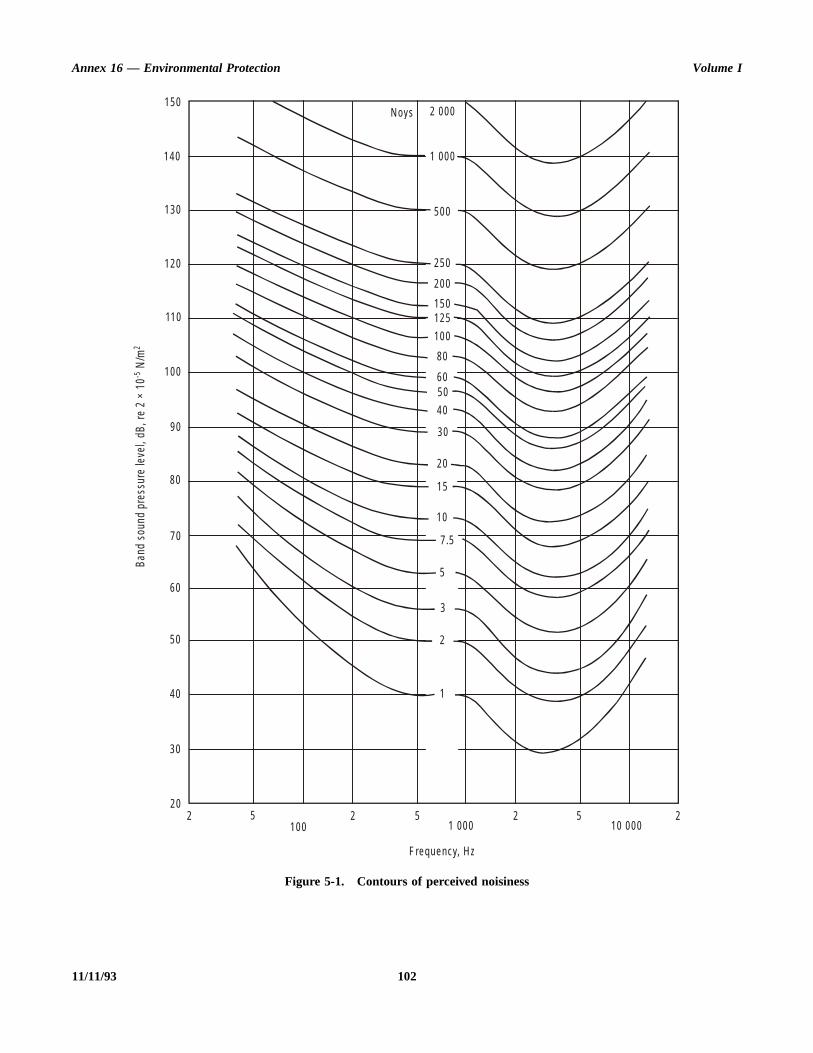
Annex 16 — Environmental Protection Volume I
11/11/93 102
Figure 5-1. Contours of perceived noisiness
100 1 0005 2 5 2 5 2
10 0002
20
30
40
50
60
70
80
90
100
110
120
130
140
150
F requency, H z
1
2
3
5
7 .5
10
15
20
30
40
5060
80
100
125150
200
250
500
1 000
2 000N oys
Band
sou
nd p
ress
ure
leve
l, dB
, re
2 ×
10 N
/m-5
2

Appendix 5 Annex 16 — Environmental Protection
end
ctedld
sing
ededen ahetheneeoise
agty,heall
leofntgalgtheIniatels
debé,
Table 5-1. Approximation to the nearest decibel of the inverse ofthe 40 noy contour relative to the value at 1 000 Hz
HzdB
40–14
50–12
63–11
80–9
100–7
125–6
160–5
HzdB
200–3
250–2
315–1
4000
5000
6300
8000
HzdB
1 0000
1 250+2
1 600+6
2 000+8
2 500+10
3 150+11
4 000+11
HzdB
5 000+10
6 300+9
8 000+6
10 000+3
12 5000
Note.— Where a record of the noise as a function of time isrequired this can be obtained by recording the noise signal ona magnetic tape, a graphic level recorder or other suitableequipment.
3.5 The recording and indicating equipment shouldcomply with IEC Publication 179* regarding the dynamiccharacteristics of the indicating instrument designated as“slow”.
Note.— If the anticipated duration of the noise signal is lessthan 5 s, the dynamic characteristics designated as “fast” maybe used.
For the purpose of this note, the duration is described asthe length of the significant time history during which therecorded signal, passed through a weighting network havingan amplitude characteristic equal to the inverse 40 noycontour, remains within 10 dB of its maximum value.
3.6 The microphone system should have been originallycalibrated at a laboratory equipped for free-field calibrationand its calibration should be rechecked at least every sixmonths.
3.7 The complete measurement system prior to fieldinstallation and at periodic intervals thereafter should becalibrated in a laboratory to ensure that the frequency responseand dynamic range requirements of the system comply withthe specifications described in this document.
Note.— Direct reading measuring systems that yieldapproximate values of perceived noise levels other than thosedefined above are not meant to be excluded from use inmonitoring.
4. FIELD EQUIPMENT INSTALLATION
4.1 Microphones used for monitoring noise levels fromaircraft operations should be installed at appropriate locations
with the axis of maximum sensitivity of each microphonoriented in a direction such that the highest sensitivity to souwaves is achieved. The microphone position should be seleso that no obstruction which influences the sound fieproduced by an aircraft exists above a horizontal plane pasthrough the active centre of the microphone.
Note 1.— Monitoring microphones may need to be placin locations having substantial background noise levels causby motor vehicle traffic, children playing, etc. In thesinstances it is often expedient to locate the microphone oroof-top, telephone pole or other structure rising above tground. Consequently, it is necessary to determine background noise level and to carry out a field check, at oor more frequencies, of the over-all sensitivity of thmeasuring system after or before the measurement of the nlevel for a sequence of aircraft operations.
Note 2.— If, due to the microphone being placed instructure above the ground, it is impracticable for operatinpersonnel to calibrate it directly because of its inaccessibiliit can be useful to provide a calibrated sound source at tmicrophone location. This sound source can be a smloudspeaker, an electrostatic actuator, or similar device.
4.2 Monitoring concerns the noise produced by a singaircraft flight, by a series of flights or by a specified type aircraft, or by a large number of operations of differeaircraft. Such noise levels vary, for a specific monitorinlocation, with variations in flight procedures or meteorologicconditions. In interpretation of the results of a monitorinprocedure, consideration should therefore be given to statistical distribution of the measured noise levels. describing the results of a monitoring procedure an approprdescription of the distribution of the observed noise leveshould be provided.
* This publication was first issued in 1965 by the Bureau central la Commission électrotechnique internationale, 1 rue de VaremGeneva, Switzerland.
103 11/11/93
ndcey anis
ng
otnot
nd
at
ring
dehert
ion
entoise
hehallght
APPENDIX 6. NOISE EVALUATION METHOD FOR NOISE CERTIFICATIONOF PROPELLER-DRIVEN AEROPLANES NOT EXCEEDING 8 618 kg —
APPLICATION FOR CERTIFICATE OF AIRWORTHINESS FORTHE PROTOTYPE ACCEPTED ON OR AFTER 17 NOVEMBER 1988
Note.— See Part II, Chapter 10.
1. INTRODUCTION
Note 1.— This noise evaluation method includes:
a) noise certification test and measurement conditions;
b) noise unit;
c) measurement of aeroplane noise received on the ground;
d) adjustments to test data; and
e) reporting of data to the certificating authority andvalidity of results.
Note 2.— The instructions and procedures given in themethod are clearly delineated to ensure uniformity duringcompliance tests and to permit comparison between tests ofvarious types of aeroplanes, conducted in various geographi-cal locations. The method applies only to aeroplanes withinthe applicability clauses of Part II, Chapter 10.
2. NOISE CERTIFICATION TEST ANDMEASUREMENT CONDITIONS
2.1 General
This section prescribes the conditions under which noisecertification tests shall be conducted and the measurementprocedures that shall be used to measure the noise made by theaeroplane for which the test is conducted.
2.2 General test conditions
2.2.1 Locations for measuring noise from an aeroplane inflight shall be surrounded by relatively flat terrain havingno excessive sound absorption characteristics such as mightbe caused by thick, matted, or tall grass, shrubs, or wooded
areas. No obstructions which significantly influence the soufield from the aeroplane shall exist within a conical spaabove the measurement position, the cone being defined baxis normal to the ground and by a half-angle 75° from thaxis.
2.2.2 The tests shall be carried out under the followiatmospheric conditions:
a) no precipitation;
b) relative humidity not higher than 95 per cent and nlower than 20 per cent and ambient temperature above 35°C and not below 2°C;
c) reported wind not above 19 km/h (10 kt) and cross winot above 9 km/h (5 kt), using a 30 s average;
d) no other anomalous meteorological conditions thwould significantly affect the noise level of theaeroplane when the noise is recorded at the measupoints specified by the certificating authority; and
e) the meteorological measurements must be mabetween 1.2 m and 10 m above ground level. If tmeasurement site is within 2 000 m of an airpometeorological station, measurements from this statmay be used.
2.3 Aeroplane testing procedures
2.3.1 The test procedures and noise measuremprocedure shall be acceptable to the airworthiness and ncertificating authorities of the State issuing the certification.
2.3.2 The flight test programme shall be initiated at tmaximum take-off mass for the aeroplane, and the mass sbe adjusted to maximum take-off mass after each hour of flitime.
2.3.3 The flight test shall be conducted at Vy ±9 km/h(5 kt) indicated airspeed.
104 ANNEX 16 — VOLUME I6/11/97
No. 5
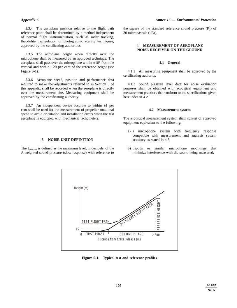
Appendix 6 Annex 16 — Environmental Protection
he
ionnd
ven
ved
sem
t;
2.3.4 The aeroplane position relative to the flight pathreference point shall be determined by a method independentof normal flight instrumentation, such as radar tracking,theodolite triangulation or photographic scaling techniques,approved by the certificating authorities.
2.3.5 The aeroplane height when directly over themicrophone shall be measured by an approved technique. Theaeroplane shall pass over the microphone within ±10° from thevertical and within ±20 per cent of the reference height (seeFigure 6-1).
2.3.6 Aeroplane speed, position and performance datarequired to make the adjustments referred to in Section 5 ofthis appendix shall be recorded when the aeroplane is directlyover the measurement site. Measuring equipment shall beapproved by the certificating authority.
2.3.7 An independent device accurate to within ±1 percent shall be used for the measurement of propeller rotationalspeed to avoid orientation and installation errors when the testaeroplane is equipped with mechanical tachometers.
3. NOISE UNIT DEFINITION
The LAmax is defined as the maximum level, in decibels, of theA-weighted sound pressure (slow response) with reference to
the square of the standard reference sound pressure (P0) of20 micropascals (µPa).
4. MEASUREMENT OF AEROPLANENOISE RECEIVED ON THE GROUND
4.1 General
4.1.1 All measuring equipment shall be approved by tcertificating authority.
4.1.2 Sound pressure level data for noise evaluatpurposes shall be obtained with acoustical equipment ameasurement practices that conform to the specifications gihereunder in 4.2.
4.2 Measurement system
The acoustical measurement system shall consist of approequipment equivalent to the following:
a) a microphone system with frequency responcompatible with measurement and analysis systeaccuracy as stated in 4.3;
b) tripods or similar microphone mountings thaminimize interference with the sound being measured
105 6/11/97
No. 5
Figure 6-1. Typical test and reference profiles
2 500SE C O N D P H ASEF IR S T PH AS E0
15
D istanc e from b rak e re lease (m )
REFERENCE FLIG HT PATH
T EST F L IGH T PATH
REF
ERE
NC
E H
EIG
HT
H e igh t (m )

Annex 16 — Environmental Protection Volume I
teredovetalandnge
nceline
cyringle
oratortory innot tofor
the0 s
nde-vells
alms,
et at. Ifthe
, a bement
ee to
o-nd.
c) recording and reproducing equipment characteristics,frequency response, and dynamic range compatiblewith the response and accuracy requirements of 4.3;and
d) acoustic calibrators using sine wave or broadband noiseof known sound pressure level. If broadband noise isused, the signal shall be described in terms of its averageand maximum root-mean-square (rms) value fornon-overload signal level.
4.3 Sensing, recording andreproducing equipment
4.3.1 The sound level produced by the aeroplane shall berecorded. A magnetic tape recorder, graphic level recorder orsound level meter is acceptable at the option of thecertificating authority.
4.3.2 The characteristics of the complete system shallcomply with the recommendations given in InternationalElectrotechnical Commission (IEC) Publication No. 651* withregard to the sections concerning microphone, amplifier andindicating instrument characteristics. The text andspecifications of IEC Publication No. 651 entitled “SoundLevel Meters” are incorporated by reference into this sectionand are made a part hereof.
Note.— If a tape recording is required by the certificatingauthority, the tape recorder shall comply with IECRecommendation 561.
4.3.3 The response of the complete system to a sensiblyplane progressive sinusoidal wave of constant amplitude shalllie within the tolerance limits specified in Table IV andTable V for Type I instruments in IEC Publication No. 651,for weighting curve “A” over the frequency range 45 to11 500 Hz.
4.3.4 The noise signal shall be passed through an “A”filter as defined in IEC Publication No. 651.
4.3.5 The over-all sensitivity of the measuring systemshall be checked before tests start and at intervals duringtesting using an acoustic calibrator generating a known soundpressure level at a known frequency.
Note.— A pistonphone operating at a nominal 124 dB and250 Hz is generally used for this purpose.
4.3.6 When a tape recording is used, the maximumA-weighted noise level LAmax may be determined using agraphic level recorder or digital equivalent.
Note.— The maximum noise level LAmax could also bedetermined using an approved sound level meter.
4.4 Noise measurementprocedures
4.4.1 The microphone shall be a 12.7 mm diamepressure type, with its protective grid, mounted in an invertposition such that the microphone diaphragm is 7 mm aband parallel to a circular metal plate. This white-painted meplate shall be 40 cm in diameter and at least 2.5 mm thick, shall be placed horizontally and flush with the surroundiground surface with no cavities below the plate. Thmicrophone shall be located three-quarters of the distafrom the centre to the edge along a radius normal to the of flight of the test aeroplane.
4.4.2 If the noise signal is tape-recorded, the frequenresponse of the electrical system shall be determined, dueach test series, at a level within 10 dB of the full-scareading used during the tests, utilizing random pseudorandom pink noise. The output of the noise genershall have been checked by an approved Standards laborawithin six months of the test series, and tolerable changesthe relative output at each one-third octave band shall be more than 0.2 dB. Sufficient determinations shall be madeensure that the over-all calibration of the system is known each test.
4.4.3 Where a magnetic tape recorder forms part of measuring chain, each reel of magnetic tape shall carry 3of this electrical calibration signal at its beginning and efor this purpose. In addition, data obtained from taprecorded signals shall be accepted as reliable only if the ledifference in the 10 kHz one-third octave band filtered leveof the two signals is not more than 0.75 dB.
4.4.4 The ambient noise, including both acousticbackground and electrical noise of the measurement systeshall be determined in the test area with the system gain slevels which will be used for aeroplane noise measurementsaeroplane peak sound pressure levels do not exceed background sound pressure levels by at least 10 dB(A)take-off measurement point nearer to the start of roll shallused and the results adjusted to the reference measurepoint by an approved method.
5. ADJUSTMENT TOTEST RESULTS
5.1 When certification test conditions differ from threference conditions appropriate adjustments shall be madthe measured noise data by the methods of this section.
* Available from the Bureau central de la Commission électrtechnique internationale, 1 rue de Varembé, Geneva, Switzerla
1066/11/97
No. 5

Appendix 6 Annex 16 — Environmental Protection
ins-
-2ed
tente
to
ight ante
in
ly
Figure 6-2. Measurement window forno absorption correction
(27ºC , 95% )(2 ºC , 95% )
(2 ºC , 80% )
90
80
70
60
50
40
30
20
10
05 10 15 20 25 30
(15ºC , 40% ) (27ºC , 40% )
R e la tivehum id ity
%
Tem pera tu re ° C
5.2 Corrections and adjustments
5.2.1 The adjustments take account of the effects of:
a) differences in atmospheric absorption betweenmeteorological test conditions and reference condi-tions;
b) differences in the noise path length between the actualaeroplane flight path and the reference flight path;
c) the change in the helical tip Mach number between testand reference conditions; and
d) the change in engine power between test and referenceconditions.
5.2.2 The noise level under reference conditions (LAmax)REF is obtained by adding increments for each of the aboveeffects to the test day noise level (LAmax) TEST.
(LAmax) REF = (LAmax) TEST + ∆(M)+ ∆1 + ∆2 + ∆3
where∆(M) is the adjustment for the change in atmospheric
absorption between test and reference conditions;∆1 is the adjustment for noise path lengths;∆2 is the adjustment for helical tip Mach number; and∆3 is the adjustment for engine power.
a) When the test conditions are within those specifiedFigure 6-2, no adjustments for differences in atmopheric absorption need be applied, i.e. ∆(M) = 0. Ifconditions are outside those specified in Figure 6then adjustments must be applied by an approvprocedure or by adding an increment ∆(M) to the testday noise levels where,
∆(M) = 0.01 (HTα – 0.2 HR)
and where HT is the height in metres of the tesaeroplane when directly over the noise measurempoint, HR is the reference height of the aeroplanabove the noise measurement point, and α is the rateof absorption at 500 Hz specified in Tables 1-5 1-16 of Appendix 1.
b) Measured noise levels should be adjusted to the heof the aeroplane over the noise measuring point onreference day by algebraically adding an incremeequal to ∆1. When test day conditions are within thosspecified in Figure 6-2:
∆1 = 22 log (HT/HR)
When test day conditions are outside those specifiedFigure 6-2:
∆1 = 20 log (HT/HR)
where HT is the height of the aeroplane when directover the noise measurement point and HR is the
107 6/11/97
No. 511/11/93

Annex 16 — Environmental Protection Volume I
detheSA
ine
ed ofe atf
ndate
elsns
ndnd
a, thedix
ndbe
e
(s)
to
reference height of the aeroplane over themeasurement point.
c) No adjustments for helical tip Mach number variationsneed be made if the propeller helical tip Mach numberis:
1) at or below 0.70 and the test helical tip Machnumber is within 0.014 of the reference helical tipMach number;
2) above 0.70 and at or below 0.80 and the test helicaltip Mach number is within 0.007 of the referencehelical tip Mach number;
3) above 0.80 and the test helical tip Mach number iswithin 0.005 of the reference helical tip Machnumber. For mechanical tachometers, if the helicaltip Mach number is above 0.8 and the test helical tipMach number is within 0.008 of the reference helicaltip Mach number.
Outside these limits measured noise levels shall beadjusted for helical tip Mach number by an incrementequal to:
∆2 = K2 log (MR/MT)
which shall be added algebraically to the measurednoise level, where MT and MR are the test andreference helical tip Mach numbers respectively. Thevalue of K2 shall be determined from approved datafrom the test aeroplane. In the absence of flight testdata and at the discretion of the certificating authoritya value of K2 = 150 may be used for MT less thanMR; however, for MT greater than or equal to MR nocorrection is applied.
Note.— The reference helical tip Mach number MR isthe one corresponding to the reference conditions abovethe measurement point:
where
where D is the propeller diameter in metres
VT is the true airspeed of the aeroplane in referenceconditions in metres per second
N is the propeller speed in reference conditions inrpm. If N is not available, its value can be taken asthe average of the propeller speeds over nominallyidentical power conditions during the flight tests.
c is the reference day speed of sound at the altituof the aeroplane in metres per second based on temperature at the reference height assuming an Itemperature lapse rate with height.
d) Measured sound levels shall be adjusted for engpower by algebraically adding an increment equal to:
∆3 = K3 log (PR/PT)
where PT and PR are the test and reference enginpowers respectively obtained from the manifolpressure/torque gauges and engine rpm. The valueK3 shall be determined from approved data from thtest aeroplane. In the absence of flight test data andthe discretion of the certificating authority a value oK3 = 17 may be used. The reference power PR shall bethat obtained at the reference height pressure atemperature assuming an ISA temperature lapse rwith height.
6. REPORTING OF DATA TO THECERTIFICATING AUTHORITYAND VALIDITY OF RESULTS
6.1 Data reporting
6.1.1 Measured and corrected sound pressure levobtained with equipment conforming to the specificatiodescribed in Section 4 of this appendix shall be reported.
6.1.2 The type of equipment used for measurement aanalysis of all acoustic aeroplane performance ameteorological data shall be reported.
6.1.3 The following atmospheric environmental datmeasured immediately before, after, or during each test atobservation points prescribed in Section 2 of this appenshall be reported:
a) air temperature and relative humidity;
b) wind speeds and wind directions; and
c) atmospheric pressure.
6.1.4 Comments on local topography, ground cover aevents that might interfere with sound recordings shall reported.
6.1.5 The following aeroplane information shall breported:
a) type, model and serial numbers of aeroplane, engineand propeller(s);
b) any modifications or nonstandard equipment likely affect the noise characteristics of the aeroplane;
MR
DπN10
------------2
VT2+1 2⁄
c----------------------------------------------=
1086/11/97
No. 5
Appendix 6 Annex 16 — Environmental Protection
sixisee
tedthe
lishngethe
c) maximum certificated take-off mass;
d) for each overflight, airspeed and air temperature at theflyover altitude determined by properly calibratedinstruments;
e) for each overflight, engine performance as manifoldpressure or power, propeller speed in revolutions perminute and other relevant parameters determined byproperly calibrated instruments;
f) aeroplane height above the measurement point; and
g) corresponding manufacturer’s data for the referenceconditions relevant to d), e) and f) above.
6.2 Validity of results
6.2.1 The measuring point shall be overflown at least times. The test results shall produce an average nolevel (LAmax) value and its 90 per cent confidence limits, thnoise level being the arithmetic average of the correcacoustical measurements for all valid test runs over measuring point.
6.2.2 The samples shall be large enough to estabstatistically a 90 per cent confidence limit not exceedi±1.5 dB(A). No test results shall be omitted from thaveraging process, unless otherwise specified by certificating authority.
109 6/11/97
No. 5
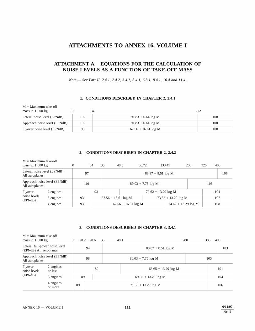
ATTACHMENTS TO ANNEX 16, VOLUME I
ATTACHMENT A. EQUATIONS FOR THE CALCULATION OFNOISE LEVELS AS A FUNCTION OF TAKE-OFF MASS
Note.— See Part II, 2.4.1, 2.4.2, 3.4.1, 5.4.1, 6.3.1, 8.4.1, 10.4 and 11.4.
1. CONDITIONS DESCRIBED IN CHAPTER 2, 2.4.1
2. CONDITIONS DESCRIBED IN CHAPTER 2, 2.4.2
3. CONDITIONS DESCRIBED IN CHAPTER 3, 3.4.1
M = Maximum take-offmass in 1 000 kg 0 34 272
Lateral noise level (EPNdB) 102 91.83 + 6.64 log M 108
Approach noise level (EPNdB) 102 91.83 + 6.64 log M 108
Flyover noise level (EPNdB) 93 67.56 + 16.61 log M 108
M = Maximum take-offmass in 1 000 kg 0 34 35 48.3 66.72 133.45 280 325 400
Lateral noise level (EPNdB)All aeroplanes
97 83.87 + 8.51 log M 106
Approach noise level (EPNdB)All aeroplanes
101 89.03 + 7.75 log M 108
Flyovernoise levels(EPNdB)
2 engines 93 70.62 + 13.29 log M 104
3 engines 93 67.56 + 16.61 log M 73.62 + 13.29 log M 107
4 engines 93 67.56 + 16.61 log M 74.62 + 13.29 log M 108
M = Maximum take-offmass in 1 000 kg 0 20.2 28.6 35 48.1 280 385 400
Lateral full-power noise level (EPNdB) All aeroplanes
94 80.87 + 8.51 log M 103
Approach noise level (EPNdB)All aeroplanes
98 86.03 + 7.75 log M 105
Flyovernoise levels(EPNdB)
2 enginesor less
89 66.65 + 13.29 log M 101
3 engines 89 69.65 + 13.29 log M 104
4 enginesor more
89 71.65 + 13.29 log M 106
ANNEX 16 — VOLUME I 111 6/11/97
No. 5

Annex 16 — Environmental Protection Volume I
4. CONDITIONS DESCRIBED IN CHAPTER 5, 5.4.1
5. CONDITIONS DESCRIBED IN CHAPTER 6, 6.3.1
6. CONDITIONS DESCRIBED IN CHAPTER 8, 8.4.1
7. CONDITIONS DESCRIBED IN CHAPTER 10, 10.4 a) and 10.4 b)
10.4 a):
10.4 b):
8. CONDITIONS DESCRIBED IN CHAPTER 11, 11.4
M = Maximum take-offmass in 1 000 kg 5.7 34.0 358.9 384.7
Lateral noise level (EPNdB) 96 85.83 + 6.64 log M 103
Approach noise level (EPNdB) 98 87.83 + 6.64 log M 105
Flyover noise level (EPNdB) 89 63.56 + 16.61 log M 106
M = Maximum take-offmass in 1 000 kg 0 0.6 1.5 8.618
Noise level in dB(A) 68 60 + 13.33 M 80
M = Maximum take-offmass in 1 000 kg 0 0.788 80.0
Take-off noise level (EPNdB) 89 90.03 + 9.97 log M 109
Approach noise level (EPNdB) 90 91.03 + 9.97 log M 110
Overflight noise level (EPNdB) 88 89.03 + 9.97 log M 108
M = Maximum take-offmass in 1 000 kg 0 0.6 1.4 8.618
Noise level in dB(A) 76 83.23 + 32.67 log M 88
M = Maximum take-offmass in 1 000 kg 0 0.57 1.5 8.618
Noise level in dB(A) 70 78.71 + 35.70 log M 85
M = Maximum take-offmass in 1 000 kg 0 0.788 2.730
Noise level in dB SEL 82 83.03 + 9.97 log M
1126/11/97
No. 5
4/11/99
No. 6

e
e
en ofofors of of
wo
han
han
ing
as
ATTACHMENT B. GUIDELINES FOR NOISE CERTIFICATION OFPROPELLER-DRIVEN STOL AEROPLANES
Note.— See Part II, Chapter 7.
Note 1.— For the purpose of these guidelines, STOLaeroplanes are those which, when operating in the shorttake-off and landing mode, consistent with the relevantairworthiness requirements, require a runway length (with nostopway or clearway) of not more than 610 m at maximumcertificated mass for airworthiness.
Note 2.— These guidelines are not applicable to aircraftwith vertical take-off and landing capabilities.
1. APPLICABILITY
The following guidelines should be applied to all propeller-driven aeroplanes of over 5 700 kg maximum certificatedtake-off mass intended for operation in the short take-off andlanding (STOL) mode, requiring a runway* length, compat-ible with the relevant take-off and landing distance require-ments, of less than 610 m at maximum certificated mass forairworthiness, and for which a certificate of airworthiness forthe individual aeroplane was first issued on or after1 January 1976.
2. NOISE EVALUATION MEASURE
The noise evaluation measure should be the effective perceivednoise level in EPNdB as described in Appendix 2 to thisvolume of the Annex.
3. NOISE MEASUREMENTREFERENCE POINTS
The aeroplane, when tested in accordance with the flight testprocedure of Section 6, should not exceed the noise levelsspecified in Section 4 at the following reference points:
a) lateral noise reference point: the point on a line parallelto, and 300 m from the runway centre line, or extendedrunway centre line, where the noise level is a maximumduring take-off or landing, with the aeroplane operatingin the STOL mode;
b) flyover noise reference point: the point on the extendedcentre line of the runway 1 500 m from the start of thtake-off roll; and
c) approach noise reference point: the point on theextended centre line of the runway 900 m from thrunway threshold.
4. MAXIMUM NOISE LEVELS
The maximum noise level at any of the reference points, whdetermined in accordance with the noise evaluation methodAppendix 2, should not exceed 96 EPNdB in the case aeroplanes with maximum certificated mass of 17 000 kg less, this limit increasing linearly with the logarithm of masat a rate of 2 EPNdB per doubling of mass in the caseaeroplanes having maximum certificated mass in excess17 000 kg.
5. TRADE-OFFS
If the maximum noise levels are exceeded at one or tmeasurement points:
a) the sum of any excesses should not be greater t4 EPNdB;
b) any excess at any single point should not be greater t3 EPNdB; and
c) any excesses should be offset by a correspondreduction at the other point or points.
6. TEST PROCEDURES
6.1 The take-off reference procedure should be follows:
* With no stopway or clearway.
ANNEX 16 — VOLUME I 113 11/11/93
Annex 16 — Environmental Protection Volume I
nednt,
be;
the
ta ofld
a) the aeroplane should be at the maximum take-offmass for which noise certification is requested;
b) the propeller and/or engine speed (rpm) and enginepower setting scheduled for STOL take-off should beused; and
c) throughout the take-off noise certification demonstrationtest, the airspeed, climb gradient, aeroplane attitude andaeroplane configuration should be those specified in theflight manual for take-off in the STOL mode.
6.2 The approach reference procedure should be asfollows:
a) the aeroplane should be at the maximum landing massfor which the noise certification is requested;
b) throughout the approach noise certificatiodemonstration test, the propeller and/or engine spe(rpm), engine power setting, airspeed, descent gradieaeroplane attitude and aeroplane configuration shouldthose specified in the flight manual for STOL landingand
c) the use of reverse thrust after landing should be maximum specified in the flight manual.
7. ADDITIONAL NOISE DATA
Where so specified by the certificating authority, dapermitting measured noise levels to be evaluated in termsthe A-weighted over-all sound pressure level (dB(A)) shoube provided.
11/11/93 114
isecingnd
toataher
pederageomfore
e of
re
n
ATTACHMENT C. GUIDELINES FOR NOISE CERTIFICATION OFINSTALLED AUXILIARY POWER UNITS (APU) AND ASSOCIATED
AIRCRAFT SYSTEMS DURING GROUND OPERATION
Note.— See Part II, Chapter 9.
1. INTRODUCTION
1.1 The following guidance material has been preparedfor the information of States establishing noise certificationrequirements for installed auxiliary power units (APU) andassociated aircraft systems used during normal groundoperation.
1.2 It should apply to installed APU and associatedaircraft systems in all aircraft for which application for acertificate of airworthiness for the prototype, or anotherequivalent prescribed procedure, is made on or after26 November 1981.
1.3 For aircraft of existing type design, for whichapplication for a change of type design involving the basicAPU installation, or another equivalent prescribed procedure,is made on or after 26 November 1981, the noise levelsproduced by installed APU and associated aircraft systemsshould not exceed those existing prior to the change, whendetermined in accordance with the following guidelines.
2. NOISE EVALUATIONPROCEDURE
The noise evaluation procedure should be according to themethods specified in Section 4.
3. MAXIMUM NOISE LEVELS
The maximum noise levels, when determined in accordancewith the noise evaluation procedure specified in Section 4,should not exceed the following:
a) 85 dB(A) at the points specified in 4.4.2.2 a), b) and c);
b) 90 dB(A) at any point on the perimeter of therectangle shown in Figure C-2.
4. NOISE EVALUATIONPROCEDURES
4.1 General
4.1.1 Test procedures are described for measuring noat specific locations (passenger and cargo doors, and servipositions) and for conducting general noise surveys arouaircraft.
4.1.2 Requirements are identified with respect instrumentation, acoustic and atmospheric environment dacquisition, reduction and presentation, and such otinformation as is needed for reporting the results.
4.1.3 Procedures involve recording data on magnetic tafor subsequent processing. The use of tape-recortime-integrating analyser systems avoids the need to averby eye the variations associated with manual readings frsound level meters and octave band analysers and thereyields more accurate results.
4.1.4 No provision is made for predicting APU noisfrom basic engine characteristics, nor for measuring noisemore than one aircraft operating at the same time.
4.2 General test conditions
4.2.1 Meteorological conditions
Wind: not more than 19 km/h (10 kt).
Temperature: not less than 2°C nor more than 35°C.
Humidity: relative humidity not less than 30 per cent nor mothan 90 per cent.
Precipitation: none.
Barometric pressure: not less than 800 hPa nor more tha1 100 hPa.
ANNEX 16 — VOLUME I 115 11/11/93

Annex 16 — Environmental Protection Volume I
nce
ise,he
Hzedst
oruldredpe
ennstoof
ave
e-
;
of
to behisf ats ofm
4.2.2 Test site
The ground between microphone and aircraft should be asmooth, hard surface. No obstructions should be presentbetween aircraft and measurement positions and no reflectingsurfaces (except the ground and aircraft) should be nearenough to sound paths to significantly influence results.Surface of the ground surrounding the aircraft should besensibly flat and level at least over an area formed byboundaries parallel to and 60 m beyond the outermostmicrophone array identified in 4.4.2.2 d).
4.2.3 Ambient noise
Ambient noise of the measurement system and test area (thatis, composite of the noise due to environmental backgroundand the electrical noise of the acoustic instrumentation) shouldbe determined.
4.2.4 APU installation
Pertinent APU and associated aircraft systems should be testedfor each aircraft model for which acoustic data arerequired.
4.2.5 Aircraft groundconfiguration
Aircraft flight control surfaces should be in the “neutral” or“clean” configuration, with gust locks on, or as stated in theaircraft’s approved operating manual for aircraft undergoingservicing.
4.3 Instrumentation
4.3.1 Aircraft
Operation data identified in 4.5.3 should be determined fromnormal aircraft instruments and controls.
4.3.2 Acoustical
4.3.2.1 General
Instrumentation and measurement procedures should beconsistent with requirements of latest applicable issues ofappropriate standards listed in the references (see 4.6). Alldata samples should be at least 2.5 times the data reductionintegration period which in no case should be less than 8 s.
All sound pressure levels should be in decibels to a referepressure of 20 µPa.
4.3.2.2 Data acquisition systems
Instrumentation systems for recording and analysis of noshown in the block diagram of Figure C-1, should meet tfollowing specifications:
4.3.2.2.1 Microphone system
a) Over a frequency range of at least 45 Hz to 11 200the system should meet the requirements as outlinunder microphone system specifications in the lateissue of reference 10 (see 4.6).
b) Microphones should be omnidirectional, vented fpressure equalization if of condenser type, and shohave known ambient pressure and temperatucoefficients. Microphone amplifier specifications shoulbe compatible with those of the microphone and tarecorder.
c) Microphone wind screens should be employed whwind speed is in excess of 11 km/h (6 kt). Correctioas a function of frequency should be applied measured data to account for the presence microphone wind screens.
4.3.2.2.2 Tape recorder
The tape recorder may be direct record or FM and should hthe following characteristics:
dynamic range of 50 dB minimum in the octave or onthird octave bands;
tape speed accuracy within ±0.2 per cent of rated speed
wow and flutter (peak to peak) less than 0.5 per centtape speed;
maximum third harmonic distortion less than 2 per cent.
4.3.2.3 Calibration
4.3.2.3.1 Microphone
Frequency response calibration should be performed priorthe test series and a subsequent post-calibration shouldperformed within one month of the pre-calibration, witadditional calibrations made when shock or damage suspected. Response calibration should cover the range oleast 45 Hz to 11 200 Hz. Pressure response characteristicthe microphone should be corrected to obtain randoincidence calibration.
11/11/93 116
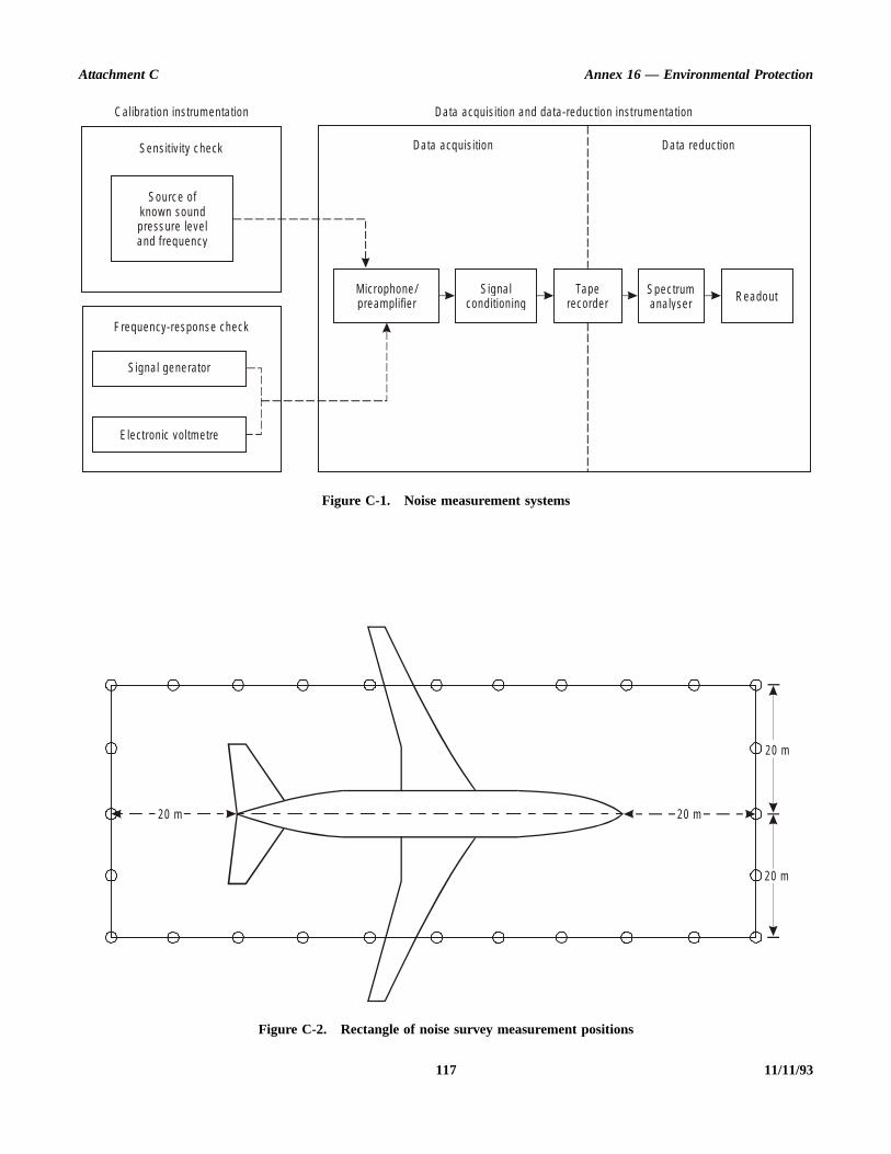
Attachment C Annex 16 — Environmental Protection
117 11/11/93
Figure C-1. Noise measurement systems
Figure C-2. Rectangle of noise survey measurement positions
Data acquis ition Da ta reduction
Da ta acquis ition and da ta -reduction instrum en ta tionCa librat ion instrum enta tion
Sens it iv ity c heck
Sourc e o fknown soundpress ure leve land f requency
F requency-response check
Signa l generator
Electron ic vo ltm e tre
M icrophone /p ream plifier
S igna lcondition ing
Taperecorder
Spec trumana lyser Readout
20 m 20 m
20 m
20 m

Annex 16 — Environmental Protection Volume I
-1ure
offorone an-vesein
imecyss
ncyforem
ntitionhensedB
B.ullthee
dB
g a ofuld
0°Cldperts.iceacy
intic
4.3.2.3.2 Recording system
a) A calibration tape, a recording of broadband noise or asweep of sinusoidal signals over a minimum frequencyrange of 45 Hz to 11 200 Hz should be recorded in thefield or in the laboratory at the beginning and end ofeach test. The tape should also include signals at thefrequencies employed during sound pressure sensitivitychecks as defined below.
b) This calibration signal, an insert voltage, should beapplied to the input and should include all signalconditioning preamplifiers, networks and recorderelectronics used to record acoustic data. In addition, a“shorted input” (i.e. microphone pressure sensitiveelement replaced with equivalent electrical impedance)recording of at least 20 s should be made as a check onsystem dynamic range and noise floor.
c) Sound pressure sensitivity calibrations with thearrangements shown in Figure C-1 should be made inthe field for each microphone prior to beginning andafter completion of measurements each day. Thesecalibrations should be made using a calibrator producinga known and constant-amplitude sound pressure level atone or more one-third octave band centre frequencies,specified in reference 11 in the frequency range from45 Hz to 11 200 Hz. A barometric correction should beapplied as required. Calibrators employed should beprecise at least to within ±0.5 dB and should have acalibration obtained according to references 6 to 9 (see4.6).
d) Each reel of tape should have comparable response andbackground noise to the calibration tape. A constantamplitude sine wave should be recorded at the start ofeach reel of tape, for reel-to-reel sound pressuresensitivity comparisons. The frequency of this sine waveshould be within the same frequency range as used forsound pressure sensitivity checks. A separate voltageinsert device or an acoustic calibrator may be used forthis purpose. If an acoustic calibrator is used, it shouldbe carefully “seated” and corrections for ambientpressure should be made so that effects of pressure oncalibrator and microphone response are eliminated.
e) Battery-driven tape recorders should be checked atfrequent intervals during a test to ensure good batterycondition. Tape recorders should not be moved whilerecording is in progress unless it has been establishedthat such movements will not change tape recordercharacteristics.
4.3.2.3.3 Data reduction equipment
Data reduction equipment should be calibrated with electricalsignals of known amplitude either at a series of discretefrequencies or with broadband signals covering the frequencyrange of 45 Hz to 11 200 Hz.
4.3.2.4 Data reduction
4.3.2.4.1 The data reduction system of Figure Cshould provide one-third or one octave band sound presslevels. Analyser filters should comply with requirements reference 12 (Class II for octave band filters and Class III one-third octave-band filters). Analyser amplitude resolutishould be no worse than 0.5 dB; dynamic range should bminimum of 50 dB between full scale and the root-measquare (rms) value of the analyser noise floor in the octaband with the highest noise floor; and amplitude responover the upper 40 dB range should be linear to with±0.5 dB.
4.3.2.4.2 Mean square sound pressures should be taveraged by integration of the squared output of frequenband filters over an integration interval that should be no lethan 8 s. All data should be processed within the frequerange from 45 Hz to 11 200 Hz. Data should be corrected all known or predictable errors, such as deviations of systfrequency response from a flat response.
4.3.2.5 Total system
4.3.2.5.1 In addition to specifications for componesystems, frequency response of the combined data acquisand reduction system should be flat within ±3 dB over tfrequency range from 45 Hz to 11 200 Hz. Frequency respogradient anywhere within this range should not exceed 5 per octave.
4.3.2.5.2 Amplitude resolution should be at least 1.0 dDynamic range should be a minimum of 45 dB between fscale and the rms value of the system noise floor in frequency band with the highest noise floor. Amplitudresponse should be linear within ±0.5 dB over the upper 35in each frequency band.
4.3.3 Meteorological
The wind speed should be measured with a device havinrange of at least 0 to 28 km/h (0-15 kt) with an accuracyat least ±2 km/h (±1 kt). Temperature measurements shobe made with a device having a range of at least 0°C to 4with an accuracy of at least ±0.5°C. Relative humidity shoube measured with a device having a range of 0 to 100 cent with an accuracy of at least ±5 percentage poinAtmospheric pressure should be measured with a devhaving a range of at least 800 to 1 100 hPa with an accurof at least ±3 hPa.
4.4 Test procedure
4.4.1 Test conditions
4.4.1.1 Ambient noise measurements should be madesufficient number to be representative for all acous
11/11/93 118

Attachment C Annex 16 — Environmental Protection
ft)
ede
) tooneromriateuldndve,Hz
d beithundthed ifise.oveford
h asof a
orrted
nt
y
he
d
elft,
measurement stations, providing correction data to apply tomeasured APU noise where necessary (see 4.4.4).
4.4.1.2 The installed APU should meet the noise levelsspecified in 3.1 at the points specified under typical loads, upto and including those imposed by the electric power generatorand air-conditioning units and any other associated systems attheir normal maximum continuous ground operation powerrequirements.
Note.— A measurement of noise from a particular model ofauxiliary power unit installed in a specific aircraft type shouldnot be deemed typical of the same equipment installed in otheraircraft types nor of other models of APU installed in the sameaircraft type.
4.4.2 Acoustical measurement locations
4.4.2.1 Except where specified otherwise, noisemeasurements should be made with microphones at 1.6 m±0.025 m (5.25 ft ±1.0 in) above the ground or surface wherepassengers or servicing personnel may stand, with themicrophone diaphragm parallel to the ground and facingupwards.
4.4.2.2 Locations for measuring noise should be asfollows:
a) cargo door locations: measurements should be made ateach cargo door location, with the door open, while theaircraft is in a typical ground handling configuration.These measurements should be taken at the centre of theopening, in the plane of the fuselage skin;
b) passenger door locations: measurements should bemade at each passenger entry door, with the door open,on the vertical centre line of the opening, in the plane ofthe fuselage skin;
c) servicing locations: measurements should be made at allservicing positions where persons are normally workingduring aircraft ground handling operations, thesepositions to be determined by reference to the approvedaircraft operating and service manuals;
d) survey locations: appropriate measurement positionsshould be chosen along the sides of a rectangle centredon the test aircraft as illustrated in Figure C-2. Thedistance between measurement positions should not begreater than 10 m for large aircraft. This distance may bereduced to accommodate small aeroplanes or to fulfilspecial requirements.
4.4.3 Meteorological measurement locations
Meteorological data should be measured at a location at thetest site within the microphone array of Figure C-2, but
upwind of the aircraft and at a height of 1.6 m (5.25 above ground level.
4.4.4 Data presentation
4.4.4.1 A-weighted sound levels should be calculatby applying frequency weighting corrections derived from thstandards for precision sound level meters (reference 10one-third or one octave band sound pressure levels. The octave band sound pressure levels may be determined fa summation of mean-square sound pressures in appropone-third octave bands. Over-all sound pressure levels shobe determined from a summation of mean-square soupressures in the 24 one-third octave, or 8 one octafrequency bands included in the frequency range from 45 to 11 200 Hz.
4.4.4.2 Over-all sound pressure levels, A-weightesound levels and one-third or one octave band data shouldpresented to the nearest decibel (dB) in tabular form, wsupplementary graphical presentations as appropriate. Sopressure levels should be corrected, if necessary, for presence of high ambient noise. No corrections are needea sound pressure level is 10 dB or more above ambient noFor sound pressure levels between 3 and 10 dB abambient noise, measured values should be corrected ambient noise by logarithmic subtraction of levels. If sounpressure levels do not exceed ambient noise by as muc3 dB, the measured values may be adjusted by means method agreed to by the certificating authority.
4.4.4.3 Acoustical data need not be normalized fatmospheric absorption losses. Test results should be repounder the actual test-day meteorological conditions.
4.5 Data reporting
4.5.1 Identification information
a) Test location, date and time of test.
b) Manufacturer and model of the APU and pertineassociated equipment.
c) Aircraft type, manufacturer, model and air registrnumber.
d) Plan and elevation views, as appropriate, of taircraft outline showing location of the APU(including inlet and exhaust ports), all associateequipment, and all acoustical measurement stations.
4.5.2 Test site description
a) Type and location of ground surfaces.
b) Location and extent of any above-ground-levreflective surfaces, such as buildings or other aircra
119 11/11/93
Annex 16 — Environmental Protection Volume I
ures
of
tic
nd
hity
ity
ureer
hity
rs,1
for
dof
ns,is
that might have been present in spite of the precautionsnoted in 4.2.2.
4.5.3 Meteorological data (for eachtest condition)
a) Wind speed, km/h (kt) and direction, degrees, relative toaircraft centre line (forward 0°).
b) Ambient temperature °C.
c) Relative humidity, per cent.
d) Barometric pressure, hPa.
4.5.4 Operational data (for eachtest condition)
a) Number of air conditioning packs operated and theirlocations.
b) APU shaft speed(s), rpm or percentage of normal rated.
c) APU normal rated shaft speed, rpm.
d) APU shaft load (kW), horse-power and/or electric poweroutput, kVA.
e) Pneumatic load, kg/min delivered by APU to allpneumatically operated aircraft systems during the test(calculated as required).
f) Temperature of APU exhaust gas at location specified inaircraft’s approved operations manual, °C.
g) Operating mode of environmental control system,cooling or heating.
h) Air conditioning distribution system supply ducttemperature, °C.
i) Events occurring during the test which may haveinfluenced the measurements.
4.5.5 Instrumentation
a) A brief description (including manufacturer and type ormodel numbers) of the acoustical and meteorologicalmeasuring instruments.
b) A brief description (including manufacturer and type ormodel numbers) of the data acquisition and dataprocessing systems.
4.5.6 Acoustical data
a) Ambient noise.
b) Acoustical data specified in 4.4.4 with a description ofcorresponding microphone locations.
c) List of standards used and description and reason forany deviations.
4.6 References
Related standard for instruments and measurement proced
1. International Electrotechnical Vocabulary, 2nd Edition,IEC-50(08) (1960).
2. Acoustic Standard Tuning Frequency, ISO-16.
3. Expression of the Physical and Subjective MagnitudesSound or Noise, ISO-131 (1959).
4. Acoustics — Preferred Reference Quantities for AcousLevels, ISO DIS 1638.2.
5. Guide to the Measurement of Acoustical Noise aEvaluation of its Effects on Man, ISO-2204 (1973).
6. Precision Method for Pressure Calibration of One-incStandard Condenser Microphone by the ReciprocTechnique, IEC-327 (1971).
7. Precision Method for Free Field Calibration of One-inchStandard Condenser Microphone by the ReciprocTechnique, IEC-486 (1974).
8. Values for the Difference between Free Field and PressSensitivity Levels for One-inch Standard CondensMicrophone, IEC-655 (1979).
9. Simplified Method for Pressure Calibration of One-incStandard Condenser Microphone by the ReciprocTechnique, IEC-402 (1972).
10. IEC Recommendations for Sound Level MeteInternational Electrotechnical Commission, IEC 65(1979).
11. ISO Recommendations for Preferred Frequencies Acoustical Measurements, International Organization forStandardization, ISO/R266-1962(E).
12. IEC Recommendations for Octave, Half-Octave anThird-Octave Band Filters Intended for the Analysis Sounds and Vibrations, International ElectrotechnicalCommission, IEC 225 (1966).
Note.— The texts and specifications of these publicatioas amended, are incorporated by reference into thattachment.
IEC publications may be obtained from:
Bureau central de la Commissionélectrotechnique internationale
1 rue de VarembéGeneva, Switzerland
ISO publications may be obtained from:
International Organization for Standardization1 rue de VarembéGeneva, Switzerland
or from State ISO member bodies.
11/11/93 120

ANNEX 16 — VOLUME I 121 11/11/93
ATTACHMENT D. GUIDELINES FOR EVALUATINGAN ALTERNATIVE METHOD OF MEASURING
HELICOPTER NOISE DURING APPROACH
Note.— The approach reference procedure of 8.6.4.1specifies a single approach path angle. This can coincide withthe impulsive noise regime for some helicopters and not forothers. In order that alternative methods of establishingcompliance may be evaluated, States are encouraged toundertake additional measurements as described below.
1. INTRODUCTION
The following guidance material has been prepared for the useof States when obtaining additional information on which afuture revision of the approach test procedures of Chapter 8may be based.
2. APPROACH NOISEEVALUATION PROCEDURE
When conducting such tests the provisions of Chapter 8 shallbe observed except as follows.
2.1 Approach reference noisemeasurement points
A flight path reference point located on the ground 120 m(395 ft) vertically below the flight paths defined in theapproach reference procedure. On level ground thiscorresponds to the following positions:
2 290 m from the intersection of the 3° approach path withthe ground plane
1 140 m from the intersection of the 6° approach path withthe ground plane
760 m from the intersection of the 9° approach path withthe ground plane.
2.2 Maximum noise levels
At the approach flight path reference point: the noise level tobe calculated by taking the arithmetical average of thecorrected levels for 3°, 6°, and 9° approaches.
2.3 Approach reference procedure
The approach reference procedure shall be established asfollows:
a) the helicopter shall be stabilized and following approachpaths of 3°, 6°, and 9°;
b) the approach shall be made at a stabilized airspeed equalto the best rate of climb speed Vy, or the lowestapproved speed for the approach, whichever is thegreater, with power stabilized during the approach andover the flight path reference point, and continued to anormal touchdown;
c) the approach shall be made with the rotor speedstabilized at the maximum normal operating rpmcertificated for approach;
d) the constant approach configuration used inairworthiness certification tests, with the landing gearextended, shall be maintained throughout the approachreference procedure; and
e) the mass of the helicopter at touchdown shall be themaximum landing mass at which noise certification isrequested.
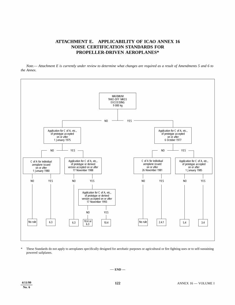
11/11/93 122 ANNEX 16 — VOLUME I
ATTACHMENT E. APPLICABILITY OF ICAO ANNEX 16NOISE CERTIFICATION STANDARDS FOR
PROPELLER-DRIVEN AEROPLANES*
Note.— Attachment E is currently under review to determine what changes are required as a result of Amendments 5 and 6 to the Annex.
* These Standards do not apply to aeroplanes specifically designed for aerobatic purposes or agricultural or fire fighting uses or to self-sustaining powered sailplanes.
— END —
MAXIMUMTAKE-OFF MASS
EXCEEDING9 000 kg
C of A for individualaeroplane issued
on or after1 January 1980
Application for C of A, etc.,of prototype accepted
on or after1 January 1975
Application for C of A, etc.,of prototype accepted
on or after6 October 1977
Application for C of A, etc.,of prototype or derived
version accepted on or after17 November 1988
C of A for individualaeroplane issued
on or after26 November 1981
Application for C of A, etc.,of prototype accepted
on or after1 January 1985
Application for C of A, etc.,of prototype or derived
version accepted on or after17 November 1993
YESNO
NO YES NO YES
NO YES NO YES NO YES NO YES
NO YES
No rule 6.3 6.3 10.4 2.4.1 5.4 3.4No rule10.4 or6.3
4/11/99
No. 6
4/1/99
Transmittal Note
SUPPLEMENT TO
ANNEX 16 — ENVIRONMENTAL PROTECTION
VOLUME I —
AIRCRAFT NOISE
(Third Edition)
1. The attached Supplement supersedes all previous Supplements to Annex 16, Volume I and includes differencesnotified by Contracting States up to 4 January 1999 with respect to all amendments up to and includingAmendment 5.
2. This Supplement should be inserted at the end of Annex 16, Volume I (Third Edition). Additional differencesreceived from Contracting States will be issued at intervals as amendments to this Supplement.
SUPPLEMENT TO ANNEX 16 — THIRD EDITION
ENVIRONMENTAL PROTECTION
Volume I — Aircraft Noise
Differences between the national regulations and practices of Contracting Statesand the corresponding International Standards and Recommended Practicescontained in Annex 16, Volume I as notified to ICAO in accordance withArticle 38 of the Convention on International Civil Aviation and the Council’sresolution of 21 November 1950.
JANUARY 1999
I N T E R N A T I O N A L C I V I L A V I A T I O N O R G A N I Z A T I O N

(ii) SUPPLEMENT TO ANNEX 16, VOLUME I (THIRD EDITION)
4/1/99
RECORD OF AMENDMENTS
No. Date Entered by No. Date Entered by
AMENDMENTS TO ANNEX 16, VOLUME I ADOPTED OR APPROVED BY THE COUNCILSUBSEQUENT TO THE THIRD EDITION ISSUED JULY 1993
No.
Date ofadoption or
approvalDate
applicable No.
Date ofadoption or
approval Date applicable
5 19/3/97 6/11/97

SUPPLEMENT TO ANNEX 16, VOLUME I (THIRD EDITION) (iii)
4/1/99
1. Contracting States which have notified ICAO of differences
The Contracting States listed below have notified ICAO of differences which exist between their national regulations andpractices and the International Standards of Annex 16, Volume I (Third Edition), up to and including Amendment 5, or havecommented on implementation.
The page numbers shown for each State and the dates of publication of those pages correspond to the actual pages in thisSupplement.
StateDate of
NotificationPages in
SupplementDate of
publication
CanadaGermanyJapanNetherlandsNew ZealandRussian FederationSwitzerlandUnited KingdomUnited States
26/9/9714/7/979/10/971/10/9717/9/9822/10/9726/9/976/10/977/11/97
11111111
1-6
4/1/994/1/994/1/994/1/994/1/994/1/994/1/994/1/994/1/99
2. Contracting States which have notified ICAO that no differences exist
StateDate of
notification StateDate of
notification
ArgentinaBahrainBarbadosCameroonChileFinlandFranceChina (Hong Kong SAR)Malaysia
30/6/979/7/9717/9/9715/9/9731/7/9710/9/9724/10/971/8/9710/6/97
NamibiaNigerNorwayPolandSamoaSaudi ArabiaSpainSwedenTunisia
22/7/9730/6/9718/4/9725/11/9720/2/987/7/97
17/10/9728/11/9716/8/97
3. Contracting States from which no information has been received
AfghanistanAlbaniaAlgeriaAngolaAntigua and BarbudaArmeniaAustraliaAustriaAzerbaijan
BahamasBangladeshBelarusBelgiumBelizeBeninBhutanBoliviaBosnia and Herzegovina
BotswanaBrazilBrunei DarussalamBulgariaBurkina FasoBurundiCambodiaCape VerdeCentral African Republic

(iv) SUPPLEMENT TO ANNEX 16, VOLUME I (THIRD EDITION)
4/1/99
ChadChinaColombiaComorosCongoCook IslandsCosta RicaCôte d’IvoireCroatiaCubaCyprusCzech RepublicDemocratic People’s Republic of KoreaDemocratic Republic of the CongoDenmarkDjiboutiDominican RepublicEcuadorEgyptEl SalvadorEquatorial GuineaEritreaEstoniaEthiopiaFijiGabonGambiaGeorgiaGhanaGreeceGrenadaGuatemalaGuineaGuinea-BissauGuyanaHaitiHondurasHungaryIcelandIndiaIndonesiaIran (Islamic Republic of)IraqIreland
IsraelItalyJamaicaJordanKazakhstanKenyaKiribatiKuwaitKyrgyzstanLao People’s Democratic RepublicLatviaLebanonLesothoLiberiaLibyan Arab JamahiriyaLithuaniaLuxembourgMadagascarMalawiMaldivesMaliMaltaMarshall IslandsMauritaniaMauritiusMexicoMicronesia (Federated States of)MonacoMongoliaMoroccoMozambiqueMyanmarNauruNepalNicaraguaNigeriaOmanPakistanPalauPanamaPapua New GuineaParaguayPeruPhilippinesPortugal
QatarRepublic of KoreaRepublic of MoldovaRomaniaRwandaSaint LuciaSaint Vincent and the GrenadinesSan MarinoSao Tome and PrincipeSenegalSeychellesSierra LeoneSingaporeSlovakiaSloveniaSolomon IslandsSomaliaSouth AfricaSri LankaSudanSurinameSwazilandSyrian Arab RepublicTajikistanThailandThe former Yugoslav Republic of MacedoniaTogoTongaTrinidad and TobagoTurkeyTurkmenistanUgandaUkraineUnited Arab EmiratesUnited Republic of TanzaniaUruguayUzbekistanVanuatuVenezuelaViet NamYemenZambiaZimbabwe
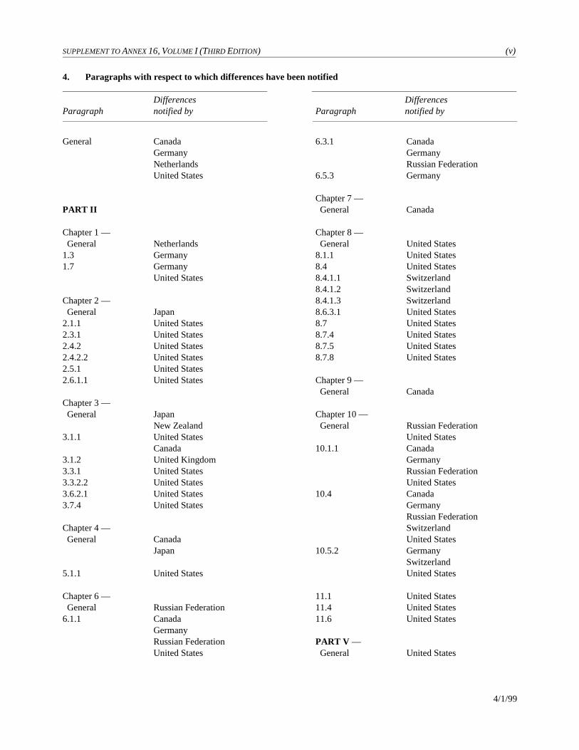
SUPPLEMENT TO ANNEX 16, VOLUME I (THIRD EDITION) (v)
4/1/99
4. Paragraphs with respect to which differences have been notified
Differences DifferencesParagraph notified by Paragraph notified by
General CanadaGermanyNetherlandsUnited States
PART II
Chapter 1 — General Netherlands1.3 Germany1.7 Germany
United States
Chapter 2 — General Japan2.1.1 United States2.3.1 United States2.4.2 United States2.4.2.2 United States2.5.1 United States2.6.1.1 United States
Chapter 3 — General Japan
New Zealand3.1.1 United States
Canada3.1.2 United Kingdom3.3.1 United States3.3.2.2 United States3.6.2.1 United States3.7.4 United States
Chapter 4 — General Canada
Japan
5.1.1 United States
Chapter 6 — General Russian Federation6.1.1 Canada
GermanyRussian FederationUnited States
6.3.1 CanadaGermanyRussian Federation
6.5.3 Germany
Chapter 7 — General Canada
Chapter 8 — General United States8.1.1 United States8.4 United States8.4.1.1 Switzerland8.4.1.2 Switzerland8.4.1.3 Switzerland8.6.3.1 United States8.7 United States8.7.4 United States8.7.5 United States8.7.8 United States
Chapter 9 — General Canada
Chapter 10 — General Russian Federation
United States10.1.1 Canada
GermanyRussian FederationUnited States
10.4 CanadaGermanyRussian FederationSwitzerlandUnited States
10.5.2 GermanySwitzerlandUnited States
11.1 United States11.4 United States11.6 United States
PART V — General United States
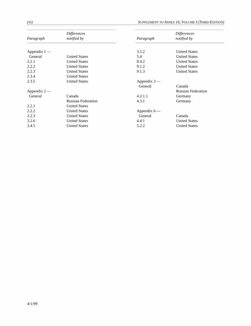
(vi) SUPPLEMENT TO ANNEX 16, VOLUME I (THIRD EDITION)
4/1/99
Differences DifferencesParagraph notified by Paragraph notified by
Appendix 1 — General United States2.2.1 United States2.2.2 United States2.2.3 United States2.3.4 United States2.3.5 United States
Appendix 2 — General Canada
Russian Federation2.2.1 United States2.2.2 United States2.2.3 United States3.2.6 United States3.4.5 United States
3.5.2 United States5.4 United States8.4.2 United States9.1.2 United States9.1.3 United States
Appendix 3 — General Canada
Russian Federation4.2.1.1 Germany4.3.1 Germany
Appendix 6 — General Canada4.4.1 United States5.2.2 United States
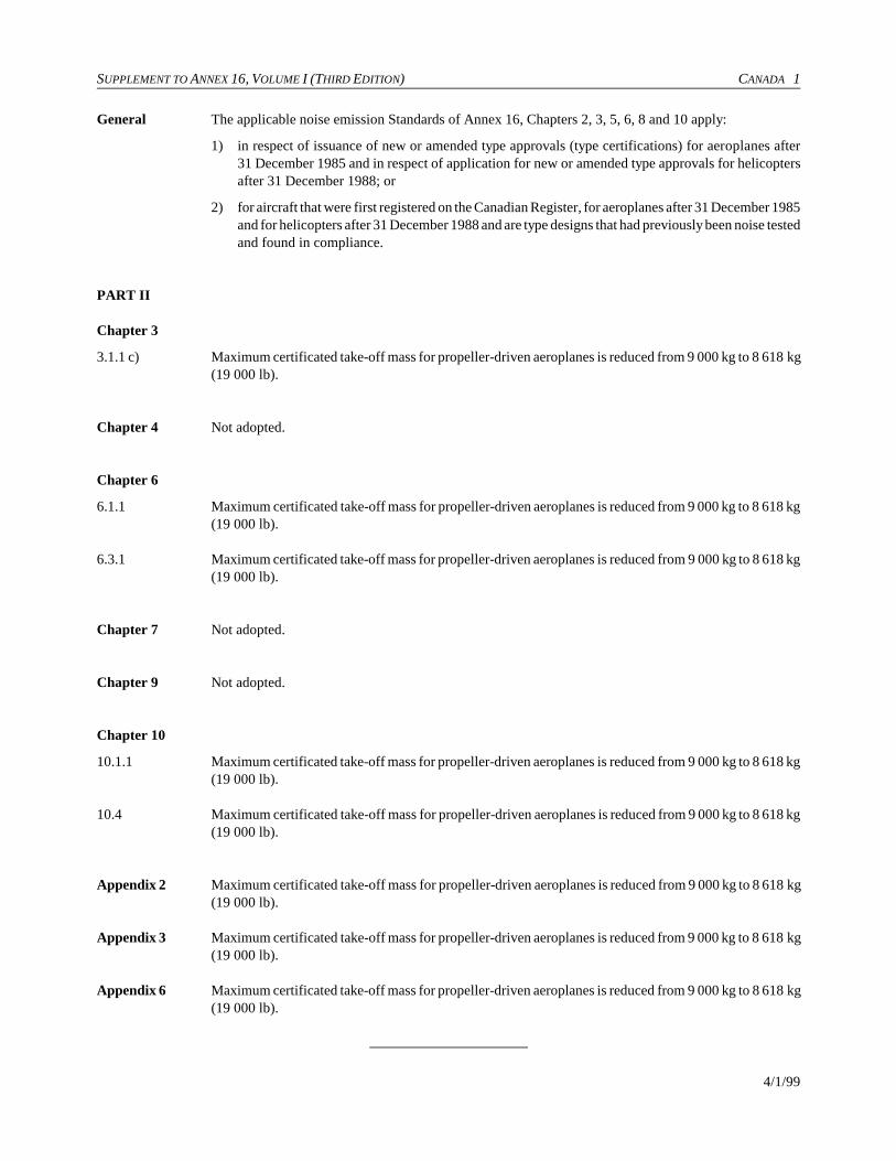
SUPPLEMENT TO ANNEX 16, VOLUME I (THIRD EDITION) CANADA 1
4/1/99
General The applicable noise emission Standards of Annex 16, Chapters 2, 3, 5, 6, 8 and 10 apply:
1) in respect of issuance of new or amended type approvals (type certifications) for aeroplanes after31 December 1985 and in respect of application for new or amended type approvals for helicoptersafter 31 December 1988; or
2) for aircraft that were first registered on the Canadian Register, for aeroplanes after 31 December 1985and for helicopters after 31 December 1988 and are type designs that had previously been noise testedand found in compliance.
PART II
Chapter 3
3.1.1 c) Maximum certificated take-off mass for propeller-driven aeroplanes is reduced from 9 000 kg to 8 618 kg(19 000 lb).
Chapter 4 Not adopted.
Chapter 6
6.1.1 Maximum certificated take-off mass for propeller-driven aeroplanes is reduced from 9 000 kg to 8 618 kg(19 000 lb).
6.3.1 Maximum certificated take-off mass for propeller-driven aeroplanes is reduced from 9 000 kg to 8 618 kg(19 000 lb).
Chapter 7 Not adopted.
Chapter 9 Not adopted.
Chapter 10
10.1.1 Maximum certificated take-off mass for propeller-driven aeroplanes is reduced from 9 000 kg to 8 618 kg(19 000 lb).
10.4 Maximum certificated take-off mass for propeller-driven aeroplanes is reduced from 9 000 kg to 8 618 kg(19 000 lb).
Appendix 2 Maximum certificated take-off mass for propeller-driven aeroplanes is reduced from 9 000 kg to 8 618 kg(19 000 lb).
Appendix 3 Maximum certificated take-off mass for propeller-driven aeroplanes is reduced from 9 000 kg to 8 618 kg(19 000 lb).
Appendix 6 Maximum certificated take-off mass for propeller-driven aeroplanes is reduced from 9 000 kg to 8 618 kg(19 000 lb).
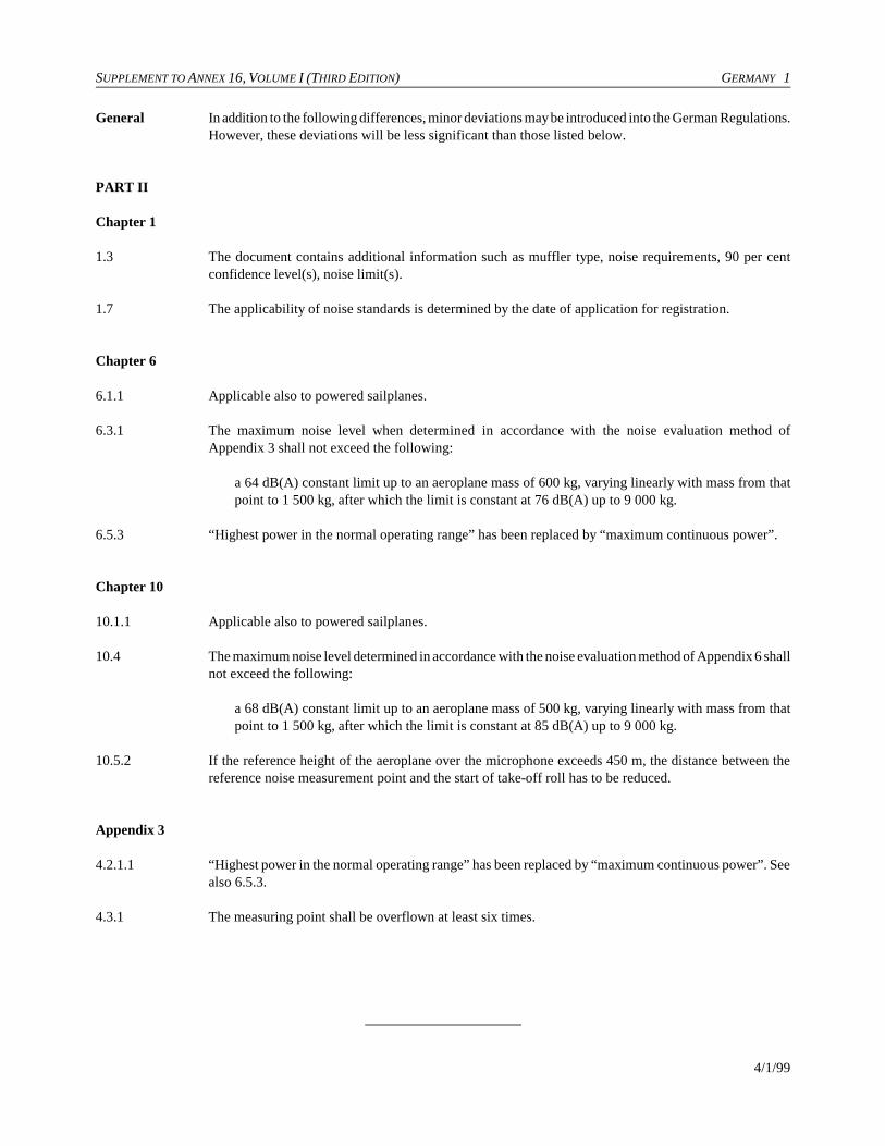
SUPPLEMENT TO ANNEX 16, VOLUME I (THIRD EDITION) GERMANY 1
4/1/99
General In addition to the following differences, minor deviations may be introduced into the German Regulations.However, these deviations will be less significant than those listed below.
PART II
Chapter 1
1.3 The document contains additional information such as muffler type, noise requirements, 90 per centconfidence level(s), noise limit(s).
1.7 The applicability of noise standards is determined by the date of application for registration.
Chapter 6
6.1.1 Applicable also to powered sailplanes.
6.3.1 The maximum noise level when determined in accordance with the noise evaluation method ofAppendix 3 shall not exceed the following:
a 64 dB(A) constant limit up to an aeroplane mass of 600 kg, varying linearly with mass from thatpoint to 1 500 kg, after which the limit is constant at 76 dB(A) up to 9 000 kg.
6.5.3 “Highest power in the normal operating range” has been replaced by “maximum continuous power”.
Chapter 10
10.1.1 Applicable also to powered sailplanes.
10.4 The maximum noise level determined in accordance with the noise evaluation method of Appendix 6 shallnot exceed the following:
a 68 dB(A) constant limit up to an aeroplane mass of 500 kg, varying linearly with mass from thatpoint to 1 500 kg, after which the limit is constant at 85 dB(A) up to 9 000 kg.
10.5.2 If the reference height of the aeroplane over the microphone exceeds 450 m, the distance between thereference noise measurement point and the start of take-off roll has to be reduced.
Appendix 3
4.2.1.1 “Highest power in the normal operating range” has been replaced by “maximum continuous power”. Seealso 6.5.3.
4.3.1 The measuring point shall be overflown at least six times.

SUPPLEMENT TO ANNEX 16, VOLUME I (THIRD EDITION) JAPAN 1
4/1/99
PART II
Chapter 2 Under the laws and regulations of Japan, noise certification is required for all aeroplanes equipped withturbo-jet engines, including those aeroplanes which are exempted by 2.1.1 a), b) and c). The operationof turbo-jet aeroplanes which do not meet the Standards of Chapter 3 is restricted under the conditionsspecified in Assembly Resolution A28-3 “Possible operating restrictions on subsonic jet aircraft whichexceed the noise levels in Volume I, Chapter 3 of Annex 16”.
Secretariat Note.— Assembly Resolution A28-3 was consolidated into Resolution A31-11 which has nowbeen superseded by Resolution A32-8.
Chapter 3 For propeller-driven aeroplanes, including their derived versions, for which the Standards of Chapter
3 are applicable, the requirement for lateral noise in 3.3.1 a) 1) shall be alternatively permitted, if
either the application for a Certificate of Airworthiness for the prototype is accepted or another
equivalent prescribed procedure is carried out by the certificating authority before 19 March 2002.
Chapter 4 Since the laws and regulations of Japan do not differentiate between supersonic aeroplanes and subsonicaeroplanes, the noise Standards of Annex 16 that are applicable to subsonic jet aeroplanes are alsoapplicable to supersonic aeroplanes.

SUPPLEMENT TO ANNEX 16, VOLUME I (THIRD EDITION) NETHERLANDS 1
4/1/99
General Currently the Netherlands requirements refer to the third edition of Annex 16, Volume I. At a date yetto be determined, all sections of Annex 16, Volume I covered by JAR 36 will be implemented by anappropriate reference in our national legislation to JAR 36, and the remaining sections will beincorporated by reference to Annex 16, Volume I, Amendment 5.
PART II
Chapter 1 A noise certificate is not routinely issued.

SUPPLEMENT TO ANNEX 16, VOLUME I (THIRD EDITION) NEW ZEALAND 1
4/1/99
PART II
Chapter 3 No person shall operate a subsonic turbo-jet aircraft of more than 34 044 kg maximum certificated take-off weight to or from any aerodrome within New Zealand after 31 March 2002 unless that aircraft hasbeen:
a) certificated under Civil Aviation Rules, Part 36 to Stage 3 noise levels prescribed in that Part; or
b) certificated by another State to the equivalent specification for Stage 3 noise levels that isacceptable to the Director of Civil Aviation.
Civil Aviation Rules, Part 36, Aircraft Noise Certification, is under development.
SUPPLEMENT TO ANNEX 16, VOLUME I (THIRD EDITION) RUSSIAN FEDERATION 1
4/1/99
PART II
Chapter 6 Instead of an 8 618 kg value for maximum take-off mass, the analogous Russian standards (AviationRegulations, Part 36) use a value of 8 600 kg. Furthermore, the Chapter 6 requirements together withthe Chapter 10 requirements are applied to aeroplanes for which the application for a certificate ofairworthiness of a prototype or derivative was adopted after 17 November 1988.
6.1.1 Instead of an 8 618 kg value for maximum take-off mass, the analogous Russian standards (AviationRegulations, Part 36) use a value of 8 600 kg.
6.3.1 Instead of an 8 618 kg value for maximum take-off mass, the analogous Russian standards (AviationRegulations, Part 36) use a value of 8 600 kg.
Note Instead of an 8 618 kg value for maximum take-off mass, the analogous Russian standards (AviationRegulations, Part 36) use a value of 8 600 kg.
Chapter 10 Instead of an 8 618 kg value for maximum take-off mass, the analogous Russian standards (AviationRegulations, Part 36) use a value of 8 600 kg. Furthermore, the Chapter 6 requirements together withthe Chapter 10 requirements are applied to aeroplanes for which the application for a certificate ofairworthiness of a prototype or derivative was adopted after 17 November 1988.
10.1.1 Instead of an 8 618 kg value for maximum take-off mass, the analogous Russian standards (AviationRegulations, Part 36) use a value of 8 600 kg.
10.4 Instead of an 8 618 kg value for maximum take-off mass, the analogous Russian standards (AviationRegulations, Part 36) use a value of 8 600 kg.
Appendix 2 Instead of an 8 618 kg value for maximum take-off mass, the analogous Russian standards (AviationRegulations, Part 36) use a value of 8 600 kg.
Appendix 3 Instead of an 8 618 kg value for maximum take-off mass, the analogous Russian standards (AviationRegulations, Part 36) use a value of 8 600 kg.

SUPPLEMENT TO ANNEX 16, VOLUME I (THIRD EDITION) SWITZERLAND 1
4/1/99
PART II
Chapter 8
8.4.1.1 The maximum permitted noise levels are 3 dB below the limits determined in accordance with 8.4.1.1.
8.4.1.2 The maximum permitted noise levels are 3 dB below the limits determined in accordance with 8.4.1.2.
8.4.1.3 The maximum permitted noise levels are 3 dB below the limits determined in accordance with 8.4.1.3.
Chapter 10
10.4 A 68 dB(A) constant limit up to an aeroplane mass of 500 kg, varying linearly with mass from that pointup to 1 500 kg, after which the limit is constant at 85 dB(A).
10.5.2 The reference height of the aeroplane over the microphone shall be determined according to theprocedures of this chapter except that it shall not exceed 450 m.
SUPPLEMENT TO ANNEX 16, VOLUME I (THIRD EDITION) UNITED KINGDOM 1
4/1/99
PART II
Chapter 3
3.1.2 A difference to be registered for paragraph 3.1.2 to read:
“For aeroplanes specified in 3.1.1 b) and c) the requirement for lateral noise in 3.3.1 a) shall alternativelybe permitted.”
SUPPLEMENT TO ANNEX 16, VOLUME I (THIRD EDITION) UNITED STATES 1
4/1/99
General In addition to the differences detailed below, minor deviations may be identified with respect toincorporated references, nomenclature and tolerances. These minor deviations are considered to beacceptable in the context of approved equivalent procedures and are less significant than the tableddifferences.
PART II
Chapter 1
1.7 Each person who applies for a type certificate for an aeroplane covered by Part 36, irrespective of the dateof application for the type certificate, must show compliance with 14 CFR Part 36.
Chapter 2
2.1.1 For type design change applications made after 14 August 1989, if an aeroplane is a Stage 3 aeroplaneprior to a change in type design, it must remain a Stage 3 aeroplane after the change in type designregardless of whether Stage 3 compliance was required before the change in type design.
2.3.1 a) Sideline noise is measured along a line 450 m from and parallel to the extended runway centre line fortwo- and three-engined aircraft; for four-engined aircraft, the sideline distance is 0.35 NM.
2.4.2 Noise level limits for Stage 2 derivative aircraft depend upon whether the engine by-pass ratio is less thantwo. If it is, the Stage 2 limits apply. Otherwise, the limits are the Stage 3 limits plus 3 dB or the Stage2 value, whichever is lower.
2.4.2.2 b) Take-off noise limits for three-engined, Stage 2 derivative aeroplanes with a by-pass ratio equal to orgreater than 2 are 107 EPNdB for maximum weights of 385 000 kg (850 000 lb) or more, reduced by 4dB per halving of the weight down to 92 EPNdB for maximum weights of 28 700 kg (63 177 lb) or less.Aircraft with a by-pass ratio less than 2 only need meet the Stage 2 limits.
2.5.1 Trade-off sum of excesses not greater than 3 EPNdB and no excess greater than 2 EPNdB.
2.6.1.1 For aeroplanes that do not have turbo-jet engines with a by-pass ratio of 2 or more, the following apply:
a) four-engined aeroplanes — 214 m (700 ft);
b) all other aeroplanes — 305 m (1 000 ft).
For all aeroplanes that have turbo-jet engines with a by-pass ratio of two or more, the following apply:
a) four-engined aeroplanes — 210 m (689 ft);
b) three-engined aeroplanes — 260 m (853 ft);
c) aeroplanes with fewer than three engines — 305 m (1 000 ft).
The power may not be reduced below that which will provide level flight for an engine inoperative or thatwill maintain a climb gradient of at least 4 per cent, whichever is greater.
Chapter 3
3.1.1 For type design change applications made after 14 August 1989, if an aeroplane is a Stage 3 aeroplaneprior to a change in type design, it must remain a Stage 3 aeroplane after the change in type designregardless of whether Stage 3 compliance was required before the change in type design.

2 UNITED STATES SUPPLEMENT TO ANNEX 16, VOLUME I (THIRD EDITION)
4/1/99
3.3.1 a), 2) No equivalent provision in 14 CFR Part 36.
3.3.2.2 A minimum of two microphones symmetrically positioned about the test flight track must be used todefine the maximum sideline noise. This maximum noise may be assumed to occur where the aircraftreaches 305 m (1 000 ft). 14 CFR Part 36 does not require symmetrical measurements to be made at eachand every point for propeller-driven aeroplane sideline noise determination.
3.6.2.1 c) Under 14 CFR Part 36, during each test take-off, simultaneous measurements should be made at thesideline noise measuring stations on each side of the runway and also at the take-off noise measuringstation. If test site conditions make it impractical to simultaneously measure take-off and sideline noise,and if each of the other sideline measurement requirements is met, independent measurements may bemade of the sideline noise under simulated flight path techniques. If the reference flight path includes apower cutback before the maximum sideline noise level is developed, the reduced sideline noise level,which is the maximum value developed by the simulated flight path technique, must be the certificatedsideline noise value.
d) 14 CFR Part 36 specifies the day speeds and the acoustic reference speed to be the minimum approvedvalue of V2 + 10 kt or the all-engines operating speed at 35 ft (for turbine-engine powered aeroplanes)or 50 ft (for reciprocating engine powered aeroplanes), whichever speed is greater as determined underthe regulations constituting the type certification basis of the aeroplane. Tests must be conducted at thetest day speeds ± 3 kt.
3.7.4 If a take-off test series is conducted at weights other than the maximum take-off weight for which noisecertification is requested:
a) at least one take-off test must be at or above that maximum weight;
b) each take-off test weight must be within +5 or !10 per cent of the maximum weight.
If an approach test series is conducted at weights other than the maximum landing weight for whichcertification is requested:
a) at least one approach test must be conducted at or above that maximum weight;
b) each test weight must exceed 90 per cent of the maximum landing weight.
Total EPNL adjustment for variations in approach flight path from the reference flight path and for anydifference between test engine thrust or power and reference engine thrust or power must not exceed2 EPNdB.
Chapter 5
5.1.1 Applies to all large transport category aircraft (as it does to all subsonic turbo-jet aircraft regardless ofcategory). Commuter category aircraft, propeller-driven aeroplanes below 8 640 kg (19 000 lb) are subjectto FAR Part 36, Appendix F or to Appendix G, depending upon the date of completion of the noisecertification tests.
Chapter 6
6.1.1 Applies to new, all propeller-driven aeroplane types below 19 000 lb (8 640 kg) in the normal, commuter,utility, acrobatic, transport or restricted categories for which the noise certification tests are completedbefore 22 December 1988.

SUPPLEMENT TO ANNEX 16, VOLUME I (THIRD EDITION) UNITED STATES 3
4/1/99
Chapter 8
General FAR 36.1(g) defines Stage 1 and Stage 2 noise levels and Stage 1 and Stage 2 helicopters. Thesedefinitions parallel those used in FAR Part 36 for turbo-jets and are used primarily to simplify theacoustical change provisions in 36.11.
FAR 36.805(c) provides for certain derived versions of helicopters for which there are no civil prototypesto be certificated above the noise level limits.
8.1.1 a) Applicable to new helicopter types for which application for an original type certificate was made on orafter 6 March 1988.
b) Applicable only to “acoustical changes” for which application for an amended or supplemental typecertificate was made on or after 6 March 1988.
8.4 14 CFR Part 36, Appendix H specifies a slightly different rate of allowable maximum noise levels as afunction of helicopter mass. The difference can lead to a difference in the calculated maximum noiselimits of 0.1 EPNdB under certain round-off conditions.
8.6.3.1 b) Does not include the VNE speeds.
8.7 14 CFR Part 36, Appendix H does not permit certain negative corrections. Annex 16 has no equivalentprovision.
8.7.4 EPNL correction must be less than 2.0 EPNdB for any combination of lateral deviation, height, approachangle and, in the case of flyover, thrust or power.
Corrections to the measured data are required if the tests were conducted below the reference weight.
Corrections to the measured data are required if the tests were conducted at other than reference enginepower.
8.7.5 The rotor speed must be maintained within one per cent of the normal operating RPM during the take-offprocedure.
8.7.8 The helicopter shall fly within ±10E from the zenith for approach and take-off, but within ±5E from thezenith for horizontal flyover.
Chapter 10
General Exception from acoustical change rule given for aircraft with flight time prior to 1 January 1955 and landconfigured aircraft reconfigured with floats or skis.
10.1.1 Applies to new, amended or supplemental type certificates for propeller-driven aeroplanes not exceeding8 640 kg (19 000 lb) for which noise certification tests have not been completed before 22 December1988.
10.4 The maximum noise level is a constant 73 dBA up to 600 kg (1 320 lb). Above that weight, the limitincreases at the rate of 1 dBA/75 kg (1 dBA/165 lb) up to 85 dBA at 1 500 kg (3 300 lb) after which it isconstant up to and including 8 640 kg (19 000 lb).

4 UNITED STATES SUPPLEMENT TO ANNEX 16, VOLUME I (THIRD EDITION)
4/1/99
10.5.2 Second phase, paragraph d). For variable pitched propellers the definition of engine power is different inthe second segment of the reference path. Maximum continuous installed power instead of maximumpower is used.
Chapter 11
11.1 FAR Appendix J was effective 11 September 1992 and applies to those helicopters for which applicationfor a type certificate was made on or after 6 March 1986.
11.4 14 CFR Part 36, Appendix J specifies a slightly different rate of allowable maximum noise levels as afunction of helicopter mass. The difference can lead to a difference in the calculated maximum noiselimits of 0.1 EPNdB under certain round-off conditions.
11.6 14 CFR Part 36, Appendix J prescribes a ±15 m limitation on the allowed vertical deviation around thereference flight path. Annex 16 has no equivalent provision.
PART V
General No comparable provision exists in United States Federal Regulations. Any local airport proprietor maypropose noise abatement operating procedures to the FAA which reviews them for safety andappropriateness.
Appendix 1
General Sections 3, 8 and 9 of Appendix 1 which contain the technical specifications for equipment, measurementand analysis and data correction for Chapter 2 aircraft and their derivatives differ in many importantaspects from the corresponding requirements in Appendix 2 which has been updated several times. Part36 updates have generally paralleled those of Appendix 2 of Annex 16. These updated requirements areapplicable in the United States to both Stage 2 and Stage 3 aircraft and their derivatives.
2.2.1 A minimum of two microphones symmetrically positioned about the test flight track must be used todefine the maximum sideline noise. This maximum noise may be assumed to occur where the aircraftreaches 305 m (1 000 ft), except for four-engine, Stage 2 aircraft for which 439 m (1 440 ft) may be used.
2.2.2 No obstructions in the cone defined by the axis normal to the ground and the half-angle 80E from the axis.
2.2.3 c) Relative humidity and ambient temperature over the sound path between the aircraft and 10 m above theground at the noise measuring site is such that the sound attenuation in the 8 kHz one-third octave bandis not greater than 12 dB/100 m and the relative humidity is between 20 and 95 per cent. However, if thedew point and dry bulb temperature used for obtaining relative humidity are measured with a device whichis accurate to within one-half a degree Celsius, the sound attenuation rate shall not exceed 14 dB/100 min the 8 kHz one-third octave band.
d) Test site average wind not above 12 kt and average cross-wind component not above 7 kt.
2.3.4 The aircraft position along the flight path is related to the recorded noise 10 dB downpoints.
2.3.5 At least one take-off test must be a maximum take-off weight and the test weight must be within +5 or!10 per cent of maximum certificated take-off weight.
SUPPLEMENT TO ANNEX 16, VOLUME I (THIRD EDITION) UNITED STATES 5
4/1/99
Appendix 2
2.2.1 A minimum of two symmetrically placed microphones must be used to define the maximum sideline noiseat the point where the aircraft reaches 305 m.
2.2.2 When a multiple layering calculation is required, the atmosphere between the aeroplane and the groundshall be divided into layers. These layers are not required to be of equal depth and the maximum layerdepth must be 100 m.
b) 14 CFR Part 36 specifies that the lower limit of the temperature test window is 36 degrees Fahrenheit (2.2degrees Celsius). Annex 16 provides 10 degrees Celsius as the lower limit for the temperature testwindow. 14 CFR Part 36 does not specify that the airport facility used to obtain meteorological conditionmeasurements be within 2 000 m of the measurement site.
c) Part 36 imposes a limit of 14 dB/100 m in the 8 kHz one-third octave band when the temperature and dewpoint are measured with a device which is accurate to within one-half a degree Celsius.
2.2.3 14 CFR Part 36 requires that the limitations on the temperature and relative humidity test window mustapply over the whole noise propagation path between a point 10 m above the ground and the helicopter.Annex 16 specifies that the limitations on the temperature and relative humidity test window apply onlyat a point 10 m above the ground. 14 CFR Part 36 requires that corrections for sound attenuation must bebased on the average of temperature and relative humidity readings at 10 m above the ground and thehelicopter. Annex 16 implies that the corrections for sound absorption are based on the temperature andrelative humidity measured at 10 m only.
3.2.6 No equivalent requirement.
3.4.5 For each detector/integrator the response to a sudden onset or interruption of a constant sinusoidal signalat the respective one-third octave band centre frequency must be measured at sampling times 0.5, 1.0, 1.5and 2.0 seconds after the onset or interruption. The rising responses must be the following amounts beforethe steady-state level:
0.5 seconds: 4.0 ± 1.0 dB1.0 seconds: 1.75 ± 0.75 dB1.5 seconds: 1.0 ± 0.5 dB2.0 seconds: 0.6 ± 0.5 dB
Note 1 No equivalent provision in 14 CFR Part 36.
3.5.2 No equivalent requirement.
5.4 14 CFR Part 36 requires that the difference between airspeed and ground speed shall not exceed 10 ktbetween the 10 dB down time period.
8.4.2 14 CFR Part 36 specifies a value of !10 in the adjustment for duration correction. Annex 16 specifies avalue of !7.5.
9.1.2 If the correction factor exceeds 8 dB on take-off or 4 dB on approach, or the correction results in a final9.1.3 EPNL value which is within 1.0 dB of the noise level limits, the “integrated” method must be used. Note
that there is no stated requirement for the use of the “integrated” procedure on sideline and the 1.0 dB testis not tied to the amount of the adjustment on take-off.
6 UNITED STATES SUPPLEMENT TO ANNEX 16, VOLUME I (THIRD EDITION)
4/1/99
Appendix 6
4.4.1 The microphone performance, not its dimensions, is specified. The microphone must be mounted 1.2 m(4 ft) above ground level. A windscreen must be employed when the wind speed is in excess of 9 km/h(5 kt).
5.2.2 a) Reference conditions are different. Noise data outside the applicable range must be corrected to 77degrees Fahrenheit and 70 per cent humidity.
c) No equivalent provision in 14 CFR Part 36. Fixed pitched propeller-driven aeroplanes have a specialprovision. If the propeller is fixed pitched and the test power is not within 5 per cent of reference power,a helical tip Mach number correction is required.
INTERNATIONAL STANDARDSAND RECOMMENDED PRACTICES
ENVIRONMENTALPROTECTION
ANNEX 16
TO THE CONVENTION ON INTERNATIONAL CIVIL AVIATION
VOLUME II
AIRCRAFT ENGINE EMISSIONS
SECOND EDITION — JULY 1993
This edition incorporates all amendments to Annex 16, adopted by the Council prior to 25 March 1993 and supersedes on 11 November 1993
all previous editions of the Annex.
For information regarding the applicability of the Standards andRecommended Practices, see Foreword and the relevant clauses
in each Chapter.
INTERNATIONAL CIVIL AVIATION ORGANIZATION

AMENDMENTS
The issue of amendments is announced regularly in the ICAO Journal and in themonthly Supplement to the Catalogue of ICAO Publications and Audio-visualTraining Aids, which holders of this publication should consult. The space belowis provided to keep a record of such amendments.
RECORD OF AMENDMENTS AND CORRIGENDA
AMENDMENTS CORRIGENDA
No.Date
applicableDate
enteredEntered
by No.Date
of issueDate
enteredEntered
by
1-2 Incorporated in this edition
3 20/3/97
4 4/11/99
(ii)

ANNEX 16 — VOLUME II (iii) 11/11/93
TABLE OF CONTENTS
Page Page
Foreword . . . . . . . . . . . . . . . . . . . . . . . . . . . . . . . . . . . . . . . . . . . (v)
Part I. DEFINITIONS AND SYMBOLS . . . . . . . . . . . . . . 1
CHAPTER 1. Definitions . . . . . . . . . . . . . . . . . . . . . . . . . . 1
CHAPTER 2. Symbols . . . . . . . . . . . . . . . . . . . . . . . . . . . . 2
Part II. VENTED FUEL . . . . . . . . . . . . . . . . . . . . . . . . . . . . 3
CHAPTER 1. Administration. . . . . . . . . . . . . . . . . . . . . . . 3
CHAPTER 2. Prevention of intentional fuel venting . . . . 4
Part III. EMISSIONS CERTIFICATION . . . . . . . . . . . . . 5
CHAPTER 1. Administration. . . . . . . . . . . . . . . . . . . . . . . 5
CHAPTER 2. Turbo-jet and turbofan enginesintended for propulsion only at subsonic speeds . . . . . . . . . 6
2.1 General . . . . . . . . . . . . . . . . . . . . . . . . . . . . . . . . . . . . . 62.2 Smoke . . . . . . . . . . . . . . . . . . . . . . . . . . . . . . . . . . . 72.3 Gaseous emissions . . . . . . . . . . . . . . . . . . . . . . . . . 72.4 Information required . . . . . . . . . . . . . . . . . . . . . . . . 7
CHAPTER 3. Turbo-jet and turbofan enginesintended for propulsion at supersonic speeds. . . . . . . . . . . . 9
3.1 General . . . . . . . . . . . . . . . . . . . . . . . . . . . . . . . . . . 93.2 Smoke . . . . . . . . . . . . . . . . . . . . . . . . . . . . . . . . . . . 103.3 Gaseous emissions . . . . . . . . . . . . . . . . . . . . . . . . . 103.4 Information required . . . . . . . . . . . . . . . . . . . . . . . . 10
APPENDICES
APPENDIX 1. Measurement of reference pressure ratio . . . . 13
1. General . . . . . . . . . . . . . . . . . . . . . . . . . . . . . . . . . . 132. Measurement . . . . . . . . . . . . . . . . . . . . . . . . . . . . . . 13
APPENDIX 2. Smoke emission evaluation. . . . . . . . . . . . . . . 14
1. Introduction and definitions . . . . . . . . . . . . . . . . . . . . . 142. Measurement of smoke emissions . . . . . . . . . . . . . . . . 143. Calculation of smoke number from
measured data . . . . . . . . . . . . . . . . . . . . . . . . . . . . . . . . 174. Reporting of data to the certificating
authority. . . . . . . . . . . . . . . . . . . . . . . . . . . . . . . . . . . . . 17
APPENDIX 3. Instrumentation and measurementtechniques for gaseous emissions . . . . . . . . . . . . . . . . . . . . . . . . 18
1. Introduction . . . . . . . . . . . . . . . . . . . . . . . . . . . . . . . 182. Definitions . . . . . . . . . . . . . . . . . . . . . . . . . . . . . . . . 183. Data required. . . . . . . . . . . . . . . . . . . . . . . . . . . . . . 204. General arrangement of the system . . . . . . . . . . . . 205. Description of component parts . . . . . . . . . . . . . . . 206. General test procedures. . . . . . . . . . . . . . . . . . . . . . 217. Calculations . . . . . . . . . . . . . . . . . . . . . . . . . . . . . . . . . . 22
Attachment A to Appendix 3. Specification forHC analyser . . . . . . . . . . . . . . . . . . . . . . . . . . . . . . . . . . . . . . 27
Attachment B to Appendix 3. Specification forCO and CO2 analysers . . . . . . . . . . . . . . . . . . . . . . . . . . . . . 28
Attachment C to Appendix 3. Specification forNOx analyser . . . . . . . . . . . . . . . . . . . . . . . . . . . . . . . . . . . . . 29
Attachment D to Appendix 3. Calibration andtest gases . . . . . . . . . . . . . . . . . . . . . . . . . . . . . . . . . . . . . . . . 30
Attachment E to Appendix 3. The calculation ofthe emissions parameters — basis, measurementcorrections and alternative numerical method . . . . . . . . . . . 31
Attachment F to Appendix 3. Specificationsfor additional data . . . . . . . . . . . . . . . . . . . . . . . . . . . . . . . . . 34
APPENDIX 4. Specification for fuel to be used inaircraft turbine engine emission testing . . . . . . . . . . . . . . . . . . . 35
APPENDIX 5. Instrumentation and measurementtechniques for gaseous emissions fromafterburning gas turbine engines . . . . . . . . . . . . . . . . . . . . . . . . 36
1. Introduction . . . . . . . . . . . . . . . . . . . . . . . . . . . . . . . 362. Definitions . . . . . . . . . . . . . . . . . . . . . . . . . . . . . . . . 363. Data required . . . . . . . . . . . . . . . . . . . . . . . . . . . . . . 394. General arrangement of the system . . . . . . . . . . . . 395. Description of component parts . . . . . . . . . . . . . . . 396. General test procedures . . . . . . . . . . . . . . . . . . . . . . 407. Calculations . . . . . . . . . . . . . . . . . . . . . . . . . . . . . . . 41
Attachment A to Appendix 5. Specification forHC analyser . . . . . . . . . . . . . . . . . . . . . . . . . . . . . . . . . . . . . . 46
Attachment B to Appendix 5. Specification forCO and CO2 analysers . . . . . . . . . . . . . . . . . . . . . . . . . . . . . 47
Attachment C to Appendix 5. Specification forNOx analyser . . . . . . . . . . . . . . . . . . . . . . . . . . . . . . . . . . . . . 48
Attachment D to Appendix 5. Calibration andtest gases . . . . . . . . . . . . . . . . . . . . . . . . . . . . . . . . . . . . . . . . 49
Attachment E to Appendix 5. The calculation ofthe emissions parameters — basis, measurementcorrections and alternative numerical method . . . . . . . . . . . 50
Attachment F to Appendix 5. Specificationsfor additional data . . . . . . . . . . . . . . . . . . . . . . . . . . . . . . . . . 53
APPENDIX 6. Compliance procedure for gaseousemissions and smoke . . . . . . . . . . . . . . . . . . . . . . . . . . . . . . . . . 54
1. General . . . . . . . . . . . . . . . . . . . . . . . . . . . . . . . . . . . 542. Compliance procedures . . . . . . . . . . . . . . . . . . . . . . 543. Procedure in the case of failure . . . . . . . . . . . . . . . 54
ens. Itn”,
nt
duel.onthed to
setifyalrdsto.
tonedtheofephyr
eshis
ofenAOthen
n
FOREWORD
Historical background
In 1972 the United Nations Conference on the HumanEnvironment was held in Stockholm. The position of ICAO atthis Conference was developed in Assembly ResolutionA18-11 which contained the following clause among others:
“2. in fulfilling this role ICAO is conscious of the adverseenvironmental impact that may be related to aircraft activityand its responsibility and that of its member States to achievemaximum compatibility between the safe and orderlydevelopment of civil aviation and the quality of the humanenvironment;”
The 18th Assembly also adopted Resolution A18-12relating to the environment which states:
“THE ASSEMBLY:
1. REQUESTS the Council, with the assistance and co-operationof other bodies of the Organization and other internationalorganizations to continue with vigour the work related to thedevelopment of Standards, Recommended Practices andProcedures and/or guidance material dealing with the quality ofthe human environment;”
This resolution was followed up by the establishment of anICAO Action Programme Regarding the Environment. As partof this Action Programme a Study Group was established toassist the Secretariat in certain tasks related to aircraft engineemissions. As a result of the work of this Study Group, anICAO Circular entitled Control of Aircraft Engine Emissions(Circular 134) was published in 1977. This Circular containedguidance material in the form of a certification procedure forthe control of vented fuel, smoke and certain gaseousemissions for new turbo-jet and turbofan engines intended forpropulsion at subsonic speeds.
It was agreed by the Council that the subject of aircraftengine emissions was not one that was solely confined toobjective technical issues but was one that neededconsideration by experts in many fields and included the directviews of Member States. A Council committee, known as theCommittee on Aircraft Engine Emissions (CAEE) wastherefore established in 1977 to pursue a number of aspects ofthe subject.
At the second meeting of the Committee on AircraftEngine Emissions, held in May 1980, proposals were madefor material to be included in an ICAO Annex. Afteramendment following the usual consultation with MemberStates of the Organization, the proposed material was adopted
by the Council to form the text of this document. ThCouncil agreed that it was desirable to include all provisiorelating to environmental aspects of aviation in one Annextherefore renamed Annex 16 as “Environmental Protectiomaking the existing text of the Annex into “Volume I —Aircraft Noise”, the material contained in this documebecoming “Volume II — Aircraft Engine Emissions”.
Applicability
Part I of Volume II of Annex 16 contains definitions ansymbols and Part II contains Standards relating to vented fPart III contains Standards relating to emissions certificatiapplicable to the classes of aircraft engines specified in individual chapters of the Part, where such engines are fitteaircraft engaged in international civil aviation.
Action by Contracting States
Notification of differences. The attention of Contracting Stateis drawn to the obligation imposed by Article 38 of thConvention by which Contracting States are required to nothe Organization of any differences between their nationregulations and practices and the International Standacontained in this Annex and any amendments thereContracting States are invited to extend such notificationany differences from the Recommended Practices contaiin this Annex, and any amendments thereto, when notification of such differences is important for the safety air navigation. Further, Contracting States are invited to kethe Organization currently informed of any differences whicmay subsequently occur, or of the withdrawal of andifferences previously notified. A specific request fonotification of differences will be sent to Contracting Statimmediately after the adoption of each amendment to tAnnex.
The attention of States is also drawn to the provisionsAnnex 15 related to the publication of differences betwetheir national regulations and practices and the related ICStandards and Recommended Practices through Aeronautical Information Service, in addition to the obligatioof States under Article 38 of the Convention.
Use of the Annex text in national regulations. The Council,on 13 April 1948, adopted a resolution inviting the attentio
ANNEX 16 — VOLUME II (v) 11/11/93

Annex 16 — Environmental Protection Volume II
ed
ds
ndion
ofe
eebuted
eas a
ish, is ofinionon
ate
he
gns:-
of
isat
of Contracting States to the desirability of using in their ownnational regulations, as far as is practicable, the preciselanguage of those ICAO Standards that are of a regulatorycharacter and also of indicating departures from the Standards,including any additional national regulations that wereimportant for the safety or regularity of international airnavigation. Wherever possible, the provisions of this Annexhave been written in such a way as to facilitate incorporation,without major textual changes, into national legislation.
Status of Annexcomponents
An Annex is made up of the following component parts, not allof which, however, are necessarily found in every Annex; theyhave the status indicated.
1.— Material comprising the Annex proper:
a) Standards and Recommended Practices adopted by theCouncil under the provisions of the Convention. Theyare defined as follows:
Standard: Any specification for physical characteristics,configuration, matériel, performance, personnel orprocedure, the uniform application of which isrecognized as necessary for the safety or regularity ofinternational air navigation and to which ContractingStates will conform in accordance with the Convention;in the event of impossibility of compliance, notificationto the Council is compulsory under Article 38.
Recommended Practice: Any specification for physicalcharacteristics, configuration, matériel, performance,personnel or procedure, the uniform application ofwhich is recognized as desirable in the interest of safety,regularity or efficiency of international air navigation,and to which Contracting States will endeavour toconform in accordance with the Convention.
b) Appendices comprising material grouped separately forconvenience but forming part of the Standards andRecommended Practices adopted by the Council.
c) Provisions governing the applicability of the Standardsand Recommended Practices.
d) Definitions of terms used in the Standards andRecommended Practices which are not self-explanatoryin that they do not have accepted dictionary meanings. Adefinition does not have an independent status but is anessential part of each Standard and RecommendedPractice in which the term is used, since a change in themeaning of the term would affect the specification.
2.— Material approved by the Council for publication inassociation with the Standards and RecommendPractices:
a) Forewords comprising historical and explanatorymaterial based on the action of the Council anincluding an explanation of the obligations of Statewith regard to the application of the Standards aRecommended Practices ensuing from the Conventand the Resolution of Adoption.
b) Introductions comprising explanatory material intro-duced at the beginning of parts, chapters or sectionsthe Annex to assist in the understanding of thapplication of the text.
c) Notes included in the text, where appropriate, to givfactual information or references bearing on thStandards or Recommended Practices in question, not constituting part of the Standards or RecommendPractices.
d) Attachments comprising material supplementary to thStandards and Recommended Practices, or included guide to their application.
Selection of language
This Annex has been adopted in four languages — EnglFrench, Russian and Spanish. Each Contracting Staterequested to select one of those texts for the purposenational implementation and for other effects provided for the Convention, either through direct use or through translatinto its own national language, and to notify the Organizatiaccordingly.
Editorial practices
The following practice has been adhered to in order to indicat a glance the status of each statement: Standards have beenprinted in light face roman; Recommended Practices have beenprinted in light face italics, the status being indicated by tprefix Recommendation; Notes have been printed in light faceitalics, the status being indicated by the prefix Note.
It is to be noted that in the English text the followinpractice has been adhered to when writing the specificatioStandards employ the operative verb “shall” while Recommended Practices employ the operative verb “should”.
In accordance with Annex 5, the International System Units (SI) is used throughout this document.
Any reference to a portion of this document which identified by a number includes all subdivisions of thportion.
11/11/93 (vi)

Foreword Annex 16 — Environmental Protection
Table A. Amendments to Annex 16
Amendment Source(s) Subject(s)
AdoptedEffective
Applicable
1st Edition Special Meeting on Aircraft Noise in the Vicinity of Aerodromes (1969)
2 April 19712 August 19716 January 1972
1 First Meeting of the Committee on Aircraft Noise
Noise certification of future production and derived versions of subsonic jet aeroplanes and updating of terminology used to describe aircraft weight.
6 December 19726 April 197316 August 1973
2 Third Meeting of the Committee on Aircraft Noise
Noise certification of light propeller-driven aeroplanes and subsonic jet aeroplanes of 5 700 kg and less maximum certificated take-off weight and guidance on discharge of functions by States in the cases of lease, charter and interchange of aircraft.
3 April 19743 August 197427 February 1975
3(2nd Edition)
Fourth Meeting of the Committee on Aircraft Noise
Noise certification standards for future subsonic jet aeroplanes and propeller-driven aeroplanes, other than STOL aeroplanes, and guidelines for noise certification of future supersonic aeroplanes, propeller-driven STOL aeroplanes and installed APU and associated aircraft systems when operating on the ground.
21 June 197621 October 19766 October 1977
4(3rd Edition)
Fifth Meeting of the Committee on Aircraft Noise
Introduction of a new parameter, viz. number of engines in the noise certification standards for subsonic jet aeroplanes, improvements in detailed test procedures to ensure that the same level of technology is applied to all types of aircraft, and editorial changes to simplify the language and eliminate inconsistencies.
6 March 19786 July 197810 August 1978
5(Annex 16, Volume I — 1st Edition)
Sixth Meeting of the Committee on Aircraft Noise
1. Annex retitled Environmental Protection and to be issued in two volumes as follows: Volume I — Aircraft Noise (incorporating provisions in the third edition of Annex 16 as amended by Amendment 5) and Volume II — Aircraft Engine Emissions.
2. Introduction in Volume I of noise certification Standards for helicopters and for future production of existing SST aeroplanes, updating of guidelines for noise certification of installed APU and associated aircraft systems and editorial amendments including changes to units of measurement to bring the Annex in line with Annex 5 provisions.
11 May 198111 September 198126 November 1981
6(Annex 16,
Volume II —1st Edition
Second Meeting of the Committee on Aircraft Engine Emissions
Introduction of Volume II containing Standards relating to the control of fuel venting, smoke and gaseous emissions from newly manufactured turbo-jet and turbofan engines intended for subsonic and supersonic propulsion.
30 June 198130 October 198118 February 1982
1 First Meeting of the Committee on Aviation Environmental Protection
Changes in test fuel specifications, Appendix 4. 4 March 198831 July 198817 November 1988
2(2nd Edition)
Second Meeting of the Committee on Aviation Environmental Protection
a) increased stringency of NOx emissions limits;
b) improvements in the smoke and gaseous emissions certification procedure.
24 March 199326 July 199311 November 1993
3 Third Meeting of the Committee on Aviation Environmental Protection
Amendment of the criteria on calibration and test gases in Appendices 3 and 5.
20 March 199720 March 1997 —
(vii) 11/11/934/11/99
No. 4

Annex 16 — Environmental Protection Volume II
4 Fourth Meeting of the Committee on Aviation Environmental Protection
Increased stringency of NOx emissions limits. 26 February 199919 July 19994 November 1999
Amendment Source(s) Subject(s)
AdoptedEffective
Applicable
11/11/93 (viii)4/11/99
No. 4

ANNEX 16 — VOLUME II 1 11/11/93
INTERNATIONAL STANDARDSAND RECOMMENDED PRACTICES
PART I. DEFINITIONS AND SYMBOLS
CHAPTER 1. DEFINITIONS
Where the following expressions are used in Volume II of thisAnnex, they have the meanings ascribed to them below:
Afterburning. A mode of engine operation wherein acombustion system fed (in whole or part) by vitiated air isused.
Approach phase. The operating phase defined by the timeduring which the engine is operated in the approach operatingmode.
Climb phase. The operating phase defined by the timeduring which the engine is operated in the climb operatingmode.
Date of manufacture. The date of issue of the documentattesting that the individual aircraft or engine as appropriateconforms to the requirements of the type or the date of ananalogous document.
Derivative version. An aircraft gas turbine engine of thesame generic family as an originally type-certificated engineand having features which retain the basic core engine andcombustor design of the original model and for which otherfactors, as judged by the certificating authority, have notchanged.
Note.— Attention is drawn to the difference between thedefinition of “derived version of aircraft” in Volume I ofAnnex 16 and the definition of “derivative version” in thisVolume.
Oxides of nitrogen. The sum of the amounts of the nitricoxide and nitrogen dioxide contained in a gas samplecalculated as if the nitric oxide were in the form of nitrogendioxide.
Rated output. For engine emissions purposes, themaximum power/thrust available for take-off under normaloperating conditions at ISA sea level static conditions withoutthe use of water injection as approved by the certificatingauthority. Thrust is expressed in kilonewtons.
Reference pressure ratio. The ratio of the mean totalpressure at the last compressor discharge plane of thecompressor to the mean total pressure at the compressor entryplane when the engine is developing take-off thrust rating inISA sea level static conditions.
Note.— Methods of measuring reference pressure ratio aregiven in Appendix 1.
Smoke. The carbonaceous materials in exhaust emissionswhich obscure the transmission of light.
Smoke Number. The dimensionless term quantifyingsmoke emissions (see 3 of Appendix 2).
Take-off phase. The operating phase defined by the timeduring which the engine is operated at the rated output.
Taxi/ground idle. The operating phases involving taxi andidle between the initial starting of the propulsion engine(s) andthe initiation of the take-off roll and between the time ofrunway turn-off and final shutdown of all propulsion engine(s).
Unburned hydrocarbons. The total of hydrocarboncompounds of all classes and molecular weights contained ina gas sample, calculated as if they were in the form ofmethane.
4/11/99
No. 4

11/11/93 2 ANNEX 16 — VOLUME II
CHAPTER 2. SYMBOLS
Where the following symbols are used in Volume II of thisAnnex, they have the meanings ascribed to them below:
CO Carbon monoxide
Dp The mass of any gaseous pollutant emitted duringthe reference emissions landing and take-off cycle
Fn Thrust in International Standard Atmosphere (ISA),sea level conditions, for the given operating mode
Foo Rated output (see definition)
F*oo Rated output with afterburning applied
HC Unburned hydrocarbons (see definition)
NO Nitric oxide
NO2 Nitrogen dioxide
NOx Oxides of nitrogen (see definition)
SN Smoke Number (see definition)
πoo Reference pressure ratio (see definition)

ANNEX 16 — VOLUME II 3 11/11/93
PART II. VENTED FUEL
CHAPTER 1. ADMINISTRATION
1.1 The provision of this Part shall apply to all turbineengine powered aircraft intended for operation in internationalair navigation manufactured after 18 February 1982.
1.2 Certification related to the prevention of intentionalfuel venting shall be granted by the certificating authority onthe basis of satisfactory evidence that either the aircraft or theaircraft engines comply with requirements of Chapter 2.
Note.— The document attesting certification relating tofuel venting may take the form of a separate fuel ventingcertificate or a suitable statement contained in anotherdocument approved by the certificating authority.
1.3 Contracting States shall recognize as valid acertification relating to fuel venting granted by the certificatingauthority of another Contracting State provided therequirements under which such certification was granted arenot less stringent than the provision of Volume II of thisAnnex.
11/11/93 4 ANNEX 16 — VOLUME II
CHAPTER 2. PREVENTION OFINTENTIONAL FUEL VENTING
Aircraft shall be so designed and constructed as to prevent theintentional discharge into the atmosphere of liquid fuelfrom the fuel nozzle manifolds resulting from the process ofengine shutdown following normal flight or groundoperations.

ANNEX 16 — VOLUME II 5 11/11/93
PART III. EMISSIONS CERTIFICATION
CHAPTER 1. ADMINISTRATION
1.1 The provision of 1.2 to 1.4 shall apply to allengines included in the classifications defined for emissioncertification purposes in Chapters 2 and 3 where such enginesare fitted to aircraft engaged in international air navigation.
1.2 Emissions certification shall be granted by thecertificating authority on the basis of satisfactory evidencethat the engine complies with requirements which are at leastequal to the stringency of the provisions of Volume II of thisAnnex. Compliance with the emissions levels of Chapters 2and 3 shall be demonstrated using the procedure described inAppendix 6.
Note.— The document attesting emissions certification maytake the form of a separate emissions certificate or a suitablestatement contained in another document approved by thecertificating authority.
1.3 The document attesting emissions certification foreach individual engine shall include at least the followinginformation which is applicable to the engine type:
a) name of certificating authority;
b) manufacturer’s type and model designation;
c) statement of any additional modifications incorporatedfor the purpose of compliance with the applicableemissions certification requirements;
d) rated output;
e) reference pressure ratio;
f) a statement indicating compliance with SmokeNumber requirements;
g) a statement indicating compliance with gaseouspollutant requirements.
1.4 Contracting States shall recognize as valid emissionscertification granted by the certificating authority of anotherContracting State provided that the requirements under whichsuch certification was granted are not less stringent than theprovisions of Volume II of this Annex.

seabe
finemassnce
ificting
nd the
ofe
t be
CHAPTER 2. TURBO-JET AND TURBOFAN ENGINES INTENDED FORPROPULSION ONLY AT SUBSONIC SPEEDS
2.1 General
2.1.1 Applicability
The provisions of this chapter shall apply to all turbo-jet andturbofan engines, as further specified in 2.2 and 2.3, intendedfor propulsion only at subsonic speeds, except when certi-ficating authorities make exemptions for specific engine typesand derivative versions of such engines for which the typecertificate of the first basic type was issued or otherequivalent prescribed procedure was carried out before1 January 1965. In such cases an exemption document shall beissued by the certificating authority. The provisions of thischapter shall also apply to engines designed for applicationsthat otherwise would have been fulfilled by turbo-jet andturbofan engines.
Note.— In considering exemptions, certificating authoritiesshould take into account the probable numbers of such enginesthat will be produced and their impact on the environment.When such an exemption is granted, the certificating authorityshould consider imposing a time limit on the future productionof such engines for installation on new aircraft, althoughproduction of such engines as spares should be permittedindefinitely.
2.1.2 Emissions involved
The following emissions shall be controlled for certification ofaircraft engines:
SmokeGaseous emissions
Unburned hydrocarbons (HC);Carbon monoxide (CO); andOxides of nitrogen (NOx).
2.1.3 Units of measurement
2.1.3.1 The smoke emission shall be measured andreported in terms of Smoke Number (SN).
2.1.3.2 The mass (Dp) of the gaseous pollutant HC, CO,or NOx emitted during the reference emissions landing andtake-off (LTO) cycle, defined in 2.1.4.2 and 2.1.4.3, shall bemeasured and reported in grams.
2.1.4 Reference conditions
2.1.4.1 Atmospheric conditions
The reference atmospheric conditions shall be ISA at level except that the reference absolute humidity shall 0.00629 kg water/kg dry air.
2.1.4.2 Thrust settings
The engine shall be tested at sufficient power settings to dethe gaseous and smoke emissions of the engine so that emission rates and Smoke Numbers corrected to the refereambient conditions can be determined at the following specpercentages of rated output as agreed by the certificaauthority:
2.1.4.3 Reference emissions landing and2.1.4.3 take-off (LTO) cycle
The reference emissions LTO cycle for the calculation areporting of gaseous emissions shall be represented byfollowing time in each operating mode.
2.1.4.4 Fuel specifications
The fuel used during tests shall meet the specificationsAppendix 4. Additives used for the purpose of smoksuppression (such as organo-metallic compounds) shall nopresent.
Operating mode Thrust setting
Take-off 100 per cent Foo
Climb 85 per cent Foo
Approach 30 per cent Foo
Taxi/ground idle 7 per cent Foo
PhaseTime in operating
mode, minutes
Take-off 0.7
Climb 2.2
Approach 4.0
Taxi/ground idle 26.0
11/11/93 6 ANNEX 16 — VOLUME II
Part III — Chapter 2 Annex 16 — Environmental Protection
oflheor
oflofr
ofl
e
e
ut
e
e
2.1.5 Test conditions
2.1.5.1 The tests shall be made with the engine on itstest bed.
2.1.5.2 The engine shall be representative of thecertificated configuration (see Appendix 6); off-take bleedsand accessory loads other than those necessary for the engine’sbasic operation shall not be simulated.
2.1.6 When test conditions differ from the referenceconditions in 2.1.4 the test results shall be corrected to thereference conditions by the methods given in Appendix 3.
2.2 Smoke
2.2.1 Applicability
The provisions of 2.2.2 shall apply to engines whose date ofmanufacture is on or after 1 January 1983.
2.2.2 Regulatory Smoke Number
The Smoke Number at any thrust setting when measured andcomputed in accordance with the procedures of Appendix 2and converted to a characteristic level by the procedures ofAppendix 6 shall not exceed the level determined from thefollowing formula:
Regulatory Smoke Number = 83.6 (Foo)–0.274
or a value of 50,whichever is lower
2.3 Gaseous emissions
2.3.1 Applicability
The provisions of 2.3.2 shall apply to engines whose ratedoutput is greater than 26.7 kN and whose date of manufactureis on or after 1 January 1986 and as further specified foroxides of nitrogen.
2.3.2 Regulatory levels
Gaseous emission levels when measured and computed inaccordance with the procedures of Appendix 3 and convertedto characteristic levels by the procedures of Appendix 6 shallnot exceed the regulatory levels determined from thefollowing formulas:
Hydrocarbons (HC): Dp /Foo = 19.6
Carbon monoxide (CO): Dp /Foo = 118
Oxides of nitrogen (NOx):
a) for engines of a type or model for which the date manufacture of the first individual production modewas on or before 31 December 1995 and for which tdate of manufacture of the individual engine was on before 31 December 1999.
Dp /Foo = 40 + 2πoo
b) for engines of a type or model for which the date manufacture of the first individual production modewas after 31 December 1995 or for which the date manufacture of the individual engine was afte31 December 1999.
Dp /Foo = 32 + 1.6πoo
c) for engines of a type or model for which the date manufacture of the first individual production modewas after 31 December 2003:
1) for engines with a pressure ratio of 30 or less:
i) for engines with a maximum rated thrust of morthan 89.0 kN:
Dp /Foo = 19 + 1.6πoo
ii) for engines with a maximum rated thrust of morthan 26.7 kN but not more than 89.0 kN:
Dp /Foo = 37.572 + 1.6πoo – 0.2087Foo
2) for engines with a pressure ratio of more than 30 bless than 62.5:
i) for engines with a maximum rated thrust of morthan 89.0 kN:
Dp /Foo = 7 + 2.0πoo
ii) for engines with a maximum rated thrust of morthan 26.7 kN but not more than 89.0 kN:
Dp /Foo = 42.71 + 1.4286πoo – 0.4013Foo +0.00642πoo × Foo
3) for engines with a pressure ratio of 62.5 or more:
Dp/Foo = 32 + 1.6πoo
7 11/11/934/11/99
No. 4
Annex 16 — Environmental Protection Volume II
engserre
us
,
red
t
ousine
orl thence byted,
Note.— The characteristic level of the Smoke Number orgaseous pollutant emissions is the mean of the values of allthe engines tested, measured and corrected to the referencestandard engine and reference ambient conditions divided bythe coefficient corresponding to the number of engines tested,as shown in Appendix 6.
2.4 Informationrequired
Note.— The information required is divided into threegroups: 1) general information to identify the enginecharacteristics, the fuel used and the method of data analysis;2) the data obtained from the engine test(s); and 3) the resultsderived from the test data.
2.4.1 Generalinformation
The following information shall be provided for each enginetype for which emissions certification is sought:
a) engine identification;
b) rated output (in kilonewtons);
c) reference pressure ratio;
d) fuel specification reference;
e) fuel hydrogen/carbon ratio;
f) the methods of data acquisition;
g) the method of making corrections for ambientconditions; and
g) the method of data analysis.
2.4.2 Test information
The following information shall be provided for each engintested for certification purposes at each of the thrust settispecified in 2.1.4.2. The information shall be provided aftcorrection to the reference ambient conditions wheapplicable:
a) fuel flow (kilograms/second);
b) emission index (grams/kilogram) for each gaseopollutant; and
c) measured Smoke Number.
2.4.3 Derived information
2.4.3.1 The following derived information shall beprovided for each engine tested for certification purposes:
a) emission rate, i.e. emission index × fuel flow(grams/second) for each gaseous pollutant;
b) total gross emission of each gaseous pollutant measuover the LTO cycle (grams);
c) values of Dp /Foo for each gaseous pollutan(grams/kilonewton); and
d) maximum Smoke Number.
2.4.3.2 The characteristic Smoke Number and gasepollutant emission levels shall be provided for each engtype for which emissions certification is sought.
Note.— The characteristic level of the Smoke Numbergaseous pollutant emissions is the mean of the values of alengines tested, measured and corrected to the referestandard engine and reference ambient conditions, dividedthe coefficient corresponding to the number of engines tesas shown in Appendix 6.
11/11/93 84/11/99
No. 4

finemassnce
ificting
nd the
ofe
t be
its
CHAPTER 3. TURBO-JET AND TURBOFAN ENGINES INTENDED FORPROPULSION AT SUPERSONIC SPEEDS
3.1 General
3.1.1 Applicability
The provisions of this chapter shall apply to all turbo-jet andturbofan engines intended for propulsion at supersonic speedswhose date of manufacture is on or after 18 February 1982.
3.1.2 Emissions involved
The following emissions shall be controlled for certification ofaircraft engines:
SmokeGaseous emissions
Unburned hydrocarbons (HC);Carbon monoxide (CO); andOxides of nitrogen (NOx).
3.1.3 Units of measurement
3.1.3.1 The smoke emission shall be measured andreported in terms of Smoke Number (SN).
3.1.3.2 The mass (Dp) of the gaseous pollutants HC, CO,or NOx emitted during the reference emissions landing andtake-off (LTO) cycle, defined in 3.1.5.2 and 3.1.5.3 shall bemeasured and reported in grams.
3.1.4 Nomenclature
Throughout this chapter, where the expression F*oo is used, itshall be replaced by Foo for engines which do not employafterburning. For taxi/ground idle thrust setting, Foo shall beused in all cases.
3.1.5 Reference conditions
3.1.5.1 Atmospheric conditions
The reference atmospheric conditions shall be ISA at sealevel except that the reference absolute humidity shall be0.00629 kg water/kg dry air.
3.1.5.2 Thrust settings
The engine shall be tested at sufficient power settings to dethe gaseous and smoke emissions of the engine so that emission rates and Smoke Numbers corrected to the refereambient conditions can be determined at the following specpercentages of rated output as agreed by the certificaauthority.
3.1.5.3 Reference emissions landing and3.1.5.3 take-off (LTO) cycle)
The reference emissions LTO cycle for the calculation areporting of gaseous emissions shall be represented byfollowing time in each operating mode.
3.1.5.4 Fuel specifications
The fuel used during tests shall meet the specificationsAppendix 4. Additives used for the purpose of smoksuppression (such as organo-metallic compounds) shall nopresent.
3.1.6 Test conditions
3.1.6.1 The tests shall be made with the engine on test bed.
Operating mode Thrust setting
Take-off 100 per cent F*oo
Climb 65 per cent F*oo
Descent 15 per cent F*oo
Approach 34 per cent F*oo
Taxi/ground idle 5.8 per cent Foo
PhaseTime in operating
mode, minutes
Take-off 1.2
Climb 2.0
Descent 1.2
Approach 2.3
Taxi/ground idle 26.0
ANNEX 16 — VOLUME II 9 11/11/93
Annex 16 — Environmental Protection Volume II
byted,
eesis;he
rt:
in
t
engserre
us
3.1.6.2 The engine shall be representative of thecertificated configuration (see Appendix 6); off-take bleedsand accessory loads other than those necessary for the engine’sbasic operation shall not be simulated.
3.1.6.3 Measurements made for determination ofemission levels at the thrusts specified in 3.1.5.2 shall be madewith the afterburner operating at the level normally used, asapplicable.
3.1.7 When test conditions differ from the referenceconditions in 3.1.5, the test results shall be corrected to thereference conditions by the methods given in Appendix 5.
3.2 Smoke
3.2.1 Regulatory Smoke Number
The Smoke Number at any thrust setting when measured andcomputed in accordance with the procedures of Appendix 2and converted to a characteristic level by the procedures ofAppendix 6 shall not exceed the regulatory level determinedfrom the following formula:
Regulatory Smoke Number = 83.6 (F*oo)–0.274
or a value of 50,whichever is lower
Note.— Certificating authorities may alternatively acceptvalues determined using afterburning provided that the validityof these data is adequately demonstrated.
3.3 Gaseous emissions
3.3.1 Regulatory levels
Gaseous emission levels when measured and computed inaccordance with the procedures of Appendix 3 or Appendix 5,as applicable, and converted to characteristic levels by theprocedures of Appendix 6 shall not exceed the regulatorylevels determined from the following formulas:
Hydrocarbons (HC): Dp /F*oo = 140(0.92)πoo
Carbon monoxide (CO): Dp /F*oo = 4 550(πoo)–1.03
Oxides of nitrogen (NOx): Dp /F*oo = 36 + 2.42πoo
Note.— The characteristic level of the Smoke Number orgaseous pollutant emissions is the mean of the values of allthe engines tested, measured and corrected to the reference
standard engine and reference ambient conditions, dividedthe coefficient corresponding to the number of engines tesas shown in Appendix 6.
3.4 Information required
Note.— The information required is divided into thregroups: 1) general information to identify the engincharacteristics, the fuel used and the method of data analy2) the data obtained from the engine test(s); and 3) tresults derived from the test data.
3.4.1 The following information shall be provided foeach engine type for which emissions certification is sough
a) engine identification;
b) rated output (in kilonewtons);
c) rated output with afterburning applied, if applicable (kilonewtons);
d) reference pressure ratio;
e) fuel specification reference;
f) fuel hydrogen/carbon ratio;
g) the methods of data acquisition;
h) the method of making corrections for ambienconditions; and
i) the method of data analysis.
3.4.2 Test information
The following information shall be provided for each engintested for certification purposes at each of the thrust settispecified in 3.1.5.2. The information shall be provided aftcorrection to the reference ambient conditions wheapplicable:
a) fuel flow (kilograms/second);
b) emission index (grams/kilogram) for each gaseopollutant;
c) percentage of thrust contributed by afterburning; and
d) measured Smoke Number.
3.4.3 Derived information
3.4.3.1 The following derived information shall beprovided for each engine tested for certification purposes:
11/11/93 10

Part III — Chapter 3 Annex 16 — Environmental Protection
ousine
orl thence byted,
a) emission rate, i.e. emission index × fuel flow,(grams/second), for each gaseous pollutant;
b) total gross emission of each gaseous pollutant measuredover the LTO cycle (grams);
c) values of Dp /F*oo for each gaseous pollutant(grams/kilonewton); and
d) maximum Smoke Number.
3.4.3.2 The characteristic Smoke Number and gasepollutant emission levels shall be provided for each engtype for which emissions certification is sought.
Note.— The characteristic level of the Smoke Numbergaseous pollutant emissions is the mean of the values of alengines tested, measured and corrected to the referestandard engine and reference ambient conditions, dividedthe coefficient corresponding to the number of engines tesas shown in Appendix 6.
11 11/11/93

ANNEX 16 — VOLUME II 13 11/11/93
APPENDIX 1. MEASUREMENT OF REFERENCE PRESSURE RATIO
1. GENERAL
1.1 Pressure ratio shall be established using arepresentative engine.
1.2 Reference pressure ratio shall be derived bycorrelating measured pressure ratio with engine thrustcorrected to standard day ambient pressure and entering thiscorrelation at the standard day rated take-off thrust.
2. MEASUREMENT
2.1 Total pressure shall be measured at the lastcompressor discharge plane and the first compressor frontface by positioning at least four probes so as to divide the air
flow area into four equal sectors and taking a mean of the fourvalues obtained.
Note.— Compressor discharge total pressure may beobtained from total or static pressure measured at a positionas close as possible to the compressor discharge plane.However, the certificating authority may approve alternativemeans of estimating the compressor discharge total pressure ifthe engine is so designed that the provision of the probesreferred to above is impractical for the emissions test.
2.2 Necessary correlation factors shall be determinedduring type certification testing using a minimum of oneengine and any associated engine component tests andanalysis.
2.3 Procedures shall be acceptable to the certificatingauthority.

entken
ss
inera-be
ti-ate aer
tomichture5°Cto the
asarehe of
ed
theen
tem asss
APPENDIX 2. SMOKE EMISSION EVALUATION
1. INTRODUCTION AND DEFINITIONS
Note.— The procedures specified here are concerned withthe acquisition of representative exhaust samples and theirtransmission to, and analysis by, the emissions measuringsystem.
1.1 Variations in the procedure contained in thisAppendix shall only be allowed after prior application to andapproval by the certificating authority.
1.2 Where the following expressions and symbols areused in this Appendix, they have the meanings ascribed tothem below:
Sampling reference size. The sample mass, 16.2 kg/m2 ofstained filter area, which if passed through the filter materialresults in a change of reflectance which gives a value of theSN parameter.
Sampling size. A chosen exhaust sample, the magnitude ofwhose mass (expressed in kilograms per square metre ofstained filter surface area) lies in the range prescribed in2.5.3 h) of this Appendix which, when passed through thefilter material, causes a change in reflectance yielding a valuefor the SN′ parameter.
Sampling volume. The chosen sample volume (expressedin cubic metres) whose equivalent mass, calculated asindicated in 3 of this Appendix, conforms to the abovedefinition of sampling size.
SN. Smoke Number; Dimensionless term quantifyingsmoke emission level based upon the staining of a filter by thereference mass of exhaust gas sample, and rated on a scale of0 to 100 (see 3 of this Appendix).
SN′. Smoke Number obtained from an individual smokesample, not necessarily of the reference size, as defined in 3 ofthis Appendix.
W. Mass of individual exhaust gas smoke sample, inkilograms, calculated from the measurements of samplevolume, pressure and temperature (see 3 of this Appendix).
2. MEASUREMENT OF SMOKE EMISSIONS
2.1 Sampling probe for smoke emissions
a) The probe shall be made of stainless steel. If a mixingprobe is used, all sampling orifices shall be of equaldiameter.
b) The probe design shall be such that at least 80 per cof the pressure drop through the probe assembly is taat the orifices.
c) The number of sampling orifices shall not be lethan 12.
d) The sampling plane shall be as close to the engexhaust nozzle exit plane as permitted by considetions of engine performance but in any case shall within 0.5 nozzle diameters of the exit plane.
e) The applicant shall provide evidence to the cerficating authority, by means of detailed traverses, ththe proposed probe design and position does providrepresentative sample for each prescribed powsetting.
2.2 Sampling line forsmoke emissions
2.2.1 The sample shall be transferred from the probethe sample collection system via a line of 4.0 to 8.5 minside diameter taking the shortest route practicable whshall in no case be greater than 25 m. The line temperashall be maintained at a temperature between 60°C and 17with a stability of ±15°C, except for the distance required cool the gas from the engine exhaust temperature down toline control temperature.
2.2.2 Sampling lines shall be as “straight through” possible. Any necessary bends shall have radii which greater than 10 times the inside diameter of the lines. Tmaterial of the lines shall be such as to discourage build-upparticulate matter or static electricity.
Note.— Stainless steel, copper or carbon-loaded groundpolytetrafluoroethylene (PTFE) meet these requirements.
2.3 Smoke analysis system
Note.— The method prescribed herein is based upon measurement of the reduction in reflectance of a filter whstained by a given mass flow of exhaust sample.
The arrangement of the various components of the sysfor acquiring the necessary stained filter samples shall beshown schematically in Figure 2-1. An optional bypa
11/11/93 14 ANNEX 16 — VOLUME II

Appendix 2 Annex 16 — Environmental Protection
rnt
s
edss
ofe
to
around the volume meter may be installed to facilitate meterreading. The major elements of the system shall meet thefollowing requirements:
a) sample size measurement: a wet or dry positivedisplacement volume meter shall be used to measuresample volume to an accuracy of ±2 per cent. Thepressure and temperature at entry to this meter shall alsobe measured to accuracies of 0.2 per cent and ±2°Crespectively;
b) sample flow rate measurement: the sample flow rateshall be maintained at a value of 14 ±0.5 L/min and theflowmeter for this purpose shall be able to make thismeasurement with an accuracy of ±5 per cent;
c) filter and holder: the filter holder shall be constructed incorrosion-resistant material and shall have the flow
channel configuration shown in Figure 2-1. The filtematerial shall be Whatman type No. 4, or any equivaleapproved by the certificating authority;
d) valves: four valve elements shall be provided aindicated in Figure 2-1:
1) valve A shall be a quick-acting, full-flow, flowdiverter enabling the incoming sample to be directthrough the measuring filter or around the bypacircuits or shut off;
Note.— Valve A may, if necessary, consist two valves interlocked to give the requisitfunction.
2) valves B and C shall be throttling valves used establish the system flow rate;
15 11/11/93
Figure 2-1. Smoke analysis system
D
α
α
q
q
PLA N E OF F ILT ER
F LOW
F ILTE RH O LD ER
= 19 to 37 .5 m m
= 5° to 7 .5°
= 20° to 30°
D(SP O T D IA .)
EX H AU S TN O Z ZLE
SA M P LEPR O B E
BY -PAS S
VA LV E CVA LV E A C O AR S E
F ILTE R
SAM
PLE F ILTE R
AN DH O LD ER
VA LV E B VA LV E D
VA C U U MPU M P
F LOWR O TA -M E T ER
VO LU M EM E T ER
PR E SS U R E A N DT EM PER AT U R EM E AS U R EM EN T

Annex 16 — Environmental Protection Volume II
htber
esano-
testh
ngsbe
nestestss as
lehes”,L.
tom
o
of
3) valve D shall be a shut-off valve to enable thefilter holder to be isolated;
all valves shall be made of corrosion-resistantmaterial;
e) vacuum pump: this pump shall have a no-flow vacuumcapability of –75 kPa with respect to atmos-pheric pressure; its full-flow rate shall not be less than28 L/min at normal temperature and pressure;
f) temperature control: the incoming sample linethrough to the filter holder shall be maintained at atemperature between 60°C and 175°C with a stabilityof ±15°C;
Note.— The objective is to prevent water con-densation prior to reaching the filter holder andwithin it.
g) If it is desired to draw a higher sample flow ratethrough the probe than through the filter holder, anoptional flow splitter may be located between theprobe and valve A (Figure 2-1), to dump excess flow.The dump line shall be as close as possible to probeoff-take and shall not affect the ability of thesampling system to maintain the required 80 per centpressure drop across the probe assembly. The dumpflow may also be sent to the CO2 analyser orcomplete emissions analysis system.
h) If a flow splitter is used, a test shall be conducted todemonstrate that the flow splitter does not change thesmoke level passing to the filter holder. This may beaccomplished by reversing the outlet lines from the flowsplitter and showing that, within the accuracy of themethod, the smoke level does not change.
i) leak performance: the sub-system shall meet therequirements of the following test:
1) clamp clean filter material into holder,
2) shut off valve A, fully open valves B, C and D.
3) run vacuum pump for one minute to reach equi-librium conditions;
4) continue to pump and measure the volume flowthrough the meter over a period of five minutes.This volume shall not exceed 5 L (referred tonormal temperature and pressure) and the systemshall not be used until this standard has beenachieved.
j) reflectometer: the measurements of the reflectance ofthe filter material shall be by an instrument conform-ing to the American National Standards Institute(ANSI) Standard No. PH2.17/1977 for diffuser reflec-
tion density. The diameter of the reflectometer ligbeam on the filter paper shall not exceed D/2 nor less than D/10 where D is the diameter of filtestained spot as defined in Figure 2-1.
2.4 Fuel specifications
The fuel shall meet the specifications of Appendix 4. Additivused for the purpose of smoke suppression (such as orgmetallic compounds) shall not be present.
2.5 Smoke measurement procedures
2.5.1 Engine operation
2.5.1.1 The engine shall be operated on a static facility which is suitable and properly equipped for higaccuracy performance testing.
2.5.1.2 The tests shall be made at the power settiapproved by the certificating authority. The engine shall stabilized at each setting.
2.5.2 Leakage and cleanliness checks
No measurements shall be made until all sample transfer liand valves are warmed up and stable. Prior to a series of the system shall be checked for leakage and cleanlinesfollows:
a) leakage check: isolate probe and close off end of sampline, perform leakage test as specified in 2.3 g) with texceptions that valve A is opened and set to “bypasvalve D is closed and that the leakage limit is 2 Restore probe and line interconnection;
b) cleanliness check:
1) open valves B, C and D;
2) run vacuum pump and alternately set valve A “bypass” and “sample” to purge the entire systewith clean air for five minutes;
3) set valve A to “bypass”;
4) close valve D and clamp clean filter material intholder. Open valve D;
5) set valve A to “sample” and reset back t“bypass” after 50 kg of air per square metre ofilter has passed through the filter material;
6) measure resultant filter spot SN′ as described inparagraph 3 of this Appendix.;
11/11/93 16
Appendix 2 Annex 16 — Environmental Protection
ne to
hallhetencehe
.
by
alsam
n
izeslues
e
de.ed,ous
ingor
7) if this SN′ exceeds 3, the system shall be cleaned(or otherwise rectified) until a value lower than 3is obtained.
The system shall not be used until the requirements of theseleakage and cleanliness checks have been met.
2.5.3 Smoke measurement
Smoke measurement shall be made independently of othermeasurements unless the smoke values so measured aresignificantly below the limiting values, or unless it can bedemonstrated that the smoke values from simultaneous smokeand gaseous emissions measurements are valid, in which casesmoke measurements may be made simultaneously withgaseous emissions measurements. In all cases the bend radiusrequirements for sampling lines detailed in 2.2.2 shall bestrictly observed. The smoke analysis sub-system shall be setup and conform to the specifications of 2.3. Referring toFigure 2-1, the following shall be the major operations inacquiring the stained filter specimens:
a) during engine operation with the probe in position, valveA shall not be placed in the no-flow condition, otherwiseparticulate buildup in the lines might be encouraged;
b) set valve A to “bypass”, close valve D and clamp cleanfilter into holder. Continue to draw exhaust sample in thebypass setting for at least five minutes while the engineis at or near to the requisite operating mode, valve Cbeing set to give a flow rate of 14 ±0.5 L/min;
c) open valve D and set valve A to “sample”, use valve Bto set flow rate again to value set in b);
d) set valve A to “bypass” and close valve D, clamp cleanfilter material into the holder;
e) when the engine is stabilized on condition, allow oneminute of sample flow with settings as at d);
f) open valve D, set valve A to “sample”, reset flow rate ifnecessary, and allow chosen sample volume (see h)) topass, before setting valve A back to “bypass” and closevalve D;
g) set aside stained filter for analysis, clamp clean filterinto holder;
h) the chosen sample sizes shall be such as to be withinthe range of 12 kg to 21 kg of exhaust gas per squaremetre of filter, and shall include samples which areeither at the value of 16.2 kg of exhaust gas persquare metre of filter or lie above and below that
value. The number of samples at each engioperating condition shall not be less than 3 and e)g) shall be repeated as necessary.
3. CALCULATION OF SMOKE NUMBERFROM MEASURED DATA
The stained filter specimens obtained as outlined in 2.5.3 sbe analysed using a reflectometer as specified in 2.3. Tbacking material used shall be black with an absolureflectance of less than 3 per cent. The absolute reflectareading RS of each stained filter shall be used to calculate treduction in reflectance by
SN′ = 100(1 – RS /RW )
where RW is the absolute reflectance of clean filter material
The masses of the various samples shall be calculated
W = 0.348 PV/T × 10–2(kg)
where P and T are, respectively, the sample pressure in pascand the temperature in kelvin, measured immediately upstreof the volume meter. V is the measured sample volume icubic metres.
For each engine condition in the case that the sample srange above and below the reference value, the various vaof SN′ and W shall be plotted as SN′ versus log W/A, where Ais the filter stain area (m2). Using a least squares straight linfit, the value of SN′ for W/A = 16.2 kg/m2 shall be estimatedand reported as the Smoke Number (SN) for that engine moWhere sampling at the reference size value only is employthe reported SN shall be the arithmetic average of the variindividual values of SN′.
4. REPORTING OF DATA TO THECERTIFICATING AUTHORITY
The measured data shall be reported to the certificatauthority. In addition the following data shall be reported feach test:
a) sample temperature;
b) sample pressure;
c) actual sample volume at sampling conditions;
d) actual sample flow rate at sampling conditions; and
e) leak and cleanliness checks substantiation (see 2.5.2).
17 11/11/93
o-ru-ift
ific
is
- as toheple,pm
nent the
nterment
ch
atput
ntsven
the
o-
APPENDIX 3. INSTRUMENTATION AND MEASUREMENT TECHNIQUESFOR GASEOUS EMISSIONS
1. INTRODUCTION
Note.— The procedures specified in this appendix areconcerned with the acquisition of representative exhaustsamples and their transmission to, and analysis by, theemissions measuring system. The procedures do not apply toengines employing afterburning. The methods proposed arerepresentative of the best readily available and mostestablished practice.
Variations in the procedure contained in this appendix shallonly be allowed after prior application to and approval by thecertificating authority.
2. DEFINITIONS
Where the following expressions are used in this appendix,they have the meanings ascribed to them below:
Accuracy. The closeness with which a measurementapproaches the true value established independently.
Air/fuel ratio. The mass rate of airflow through the hotsection of the engine divided by the mass rate of fuel flow tothe engine.
Calibration gas. A high accuracy reference gas to be usedfor alignment, adjustment and periodic checks of instruments.
Concentration. The volume fraction of the component ofinterest in the gas mixture — expressed as volume percentageor as parts per million.
Exhaust nozzle. In the exhaust emissions sampling of gasturbine engines where the jet effluxes are not mixed (as insome turbofan engines for example) the nozzle considered isthat for the gas generator (core) flow only. Where, however,the jet efflux is mixed the nozzle considered is the total exitnozzle.
Flame ionization detector. A hydrogen-air diffusion flamedetector that produces a signal nominally proportional to themass-flow rate of hydrocarbons entering the flame per unit oftime — generally assumed responsive to the number of carbonatoms entering the flame.
Interference. Instrument response due to presence ofcomponents other than the gas (or vapour) that is to bemeasured.
Noise. Random variation in instrument output not assciated with characteristics of the sample to which the instment is responding, and distinguishable from its drcharacteristics.
Non-dispersive infra-red analyser. An instrument that byabsorption of infra-red energy selectively measures speccomponents.
Parts per million (ppm). The unit volume concentration ofa gas per million unit volume of the gas mixture of which it a part.
Parts per million carbon (ppmC). The mole fraction ofhydrocarbon multiplied by 106 measured on a methaneequivalence basis. Thus, 1 ppm of methane is indicated1 ppmC. To convert ppm concentration of any hydrocarbonan equivalent ppmC value, multiply ppm concentration by tnumber of carbon atoms per molecule of the gas. For exam1 ppm propane translates as 3 ppmC hydrocarbon; 1 phexane as 6 ppmC hydrocarbon.
Reference gas. A mixture of gases of specified and knowcomposition used as the basis for interpreting instrumresponse in terms of the concentration of the gas to whichinstrument is responding.
Repeatability. The closeness with which a measuremeupon a given, invariant sample can be reproduced in short-trepetitions of the measurement with no intervening instrumadjustment.
Resolution. The smallest change in a measurement whican be detected.
Response. The change in instrument output signal thoccurs with change in sample concentration. Also the outsignal corresponding to a given sample concentration.
Stability. The closeness with which repeated measuremeupon a given invariant sample can be maintained over a giperiod of time.
Zero drift. Time-related deviation of instrument outpufrom zero set point when it is operating on gas free of tcomponent to be measured.
Zero gas. A gas to be used in establishing the zero, or nresponse, adjustment of an instrument.
11/11/93 18 ANNEX 16 — VOLUME II

Appendix 3 Annex 16 — Environmental Protection
19 11/11/93
Figure 3-1. Sampling and analysis system, schematic
EX H AU S TN O Z ZL E
SA M P LEPR O B E
T R AN S FE RL IN E
PU M PD U M P
PU M P
Z E R O SPA N
VE N T VE N T VE N T
H CAN A LY SIS
C OAN A LY SIS
C O 2AN A LY SIS
Z E R O
Z E R O
SPA N
SPA N
N OAN A LY SIS
x
VE N T
R EP R ES E N T S (G R O U P O F) VALV E(S) TO IM PL E M E N TR EQ U IR ED R O U T E SE L EC T IO N (S )
L IN E T EM PE R ATU R E C O N T R O L LE D AT 160 ° C
L IN E T EM PE R ATU R E C O N T R O L LE D AT 65° C
F U RT H E R N O TE S A N D D E TA IL IN T E X T
Annex 16 — Environmental Protection Volume II
mpe
teustisary
sisple, be hot
stsic
ensary,
ingal
t oft the
2;
austinezle
nghere-
theing
3. DATA REQUIRED
3.1 Gaseous emissions
Concentrations of the following emissions shall be determined:
a) Hydrocarbons (HC): a combined estimate of all hydro-carbon compounds present in the exhaust gas.
b) Carbon monoxide (CO).
c) Carbon dioxide (CO2).
Note.— CO2 is not considered a pollutant but itsconcentration is required for calculation and checkpurposes.
d) Oxides of nitrogen (NOx): an estimate of the sum ofthe two oxides, nitric oxide (NO) and nitrogendioxide (NO2).
e) Nitric oxide (NO).
3.2 Other information
In order to normalize the emissions measurement data and toquantify the engine test characteristics, the followingadditional information shall be provided:
— inlet temperature;— inlet humidity;— atmospheric pressure;— hydrogen/carbon ratio of fuel;— other required engine parameters (for example, thrust,
rotor speeds, turbine temperatures and gas-generator airflow).
This data shall be obtained either by direct measurementor by calculation, as presented in Attachment F to thisappendix.
4. GENERAL ARRANGEMENTOF THE SYSTEM
No desiccants, dryers, water traps or related equipment shallbe used to treat the exhaust sample flowing to the oxides ofnitrogen and the hydrocarbon analysis instrumentation.Requirements for the various component sub-systems aregiven in 5, but the following list gives some qualifications andvariations:
a) it is assumed that each of the various individual sub-systems includes the necessary flow control, condi-tioning and measurement facilities;
b) the necessity for a dump and/or a hot-sample puwill depend on ability to meet the sample transfer timand analysis sub-system sample flow rarequirements. This in turn depends on the exhasample driving pressure and line losses. It considered that these pumps usually will be necessat certain engine running conditions; and
c) the position of the hot pump, relative to the gas analysub-systems, may be varied as required. (For examsome HC analysers contain hot pumps and so mayjudged capable of being used upstream of the systempump.)
Note.— Figure 3-1 is a schematic drawing of the exhaugas sampling and analytical system and typifies the barequirements for emissions testing.
5. DESCRIPTION OFCOMPONENT PARTS
Note.— A general description and specification of thprincipal elements in the engine exhaust emissiomeasurement system follows. Greater detail, where necesswill be found in Attachments A, B and C to this appendix.
5.1 Sampling system
5.1.1 Sampling probe
a) The probe shall be made of stainless steel. If a mixprobe is used, all sampling orifices shall be of equdiameter;
b) the probe design shall be such that at least 80 per centhe pressure drop through the probe assembly is taken aorifices;
c) the number of sampling orifices shall not be less than 1
d) the sampling plane shall be as close to the engine exhnozzle exit plane as permitted by considerations of engperformance but in any case shall be within 0.5 nozdiameter of the exit plane; and
e) the applicant shall provide evidence to the certificatiauthority, by means of detailed traverses, that tproposed probe design and position does provide a repsentative sample for each prescribed power setting.
5.1.2 Sampling lines
The sample shall be transferred from the probe to analysers via a line of 4.0 to 8.5 mm inside diameter, tak
11/11/93 20

Appendix 3 Annex 16 — Environmental Protection
for
C
ilitycy
werne
to
tye
allialaide
eet
chest
ing
cell-nt
90ser
nt,ts.
s
the shortest route practicable and using a flow rate such thatthe transport time is less than 10 seconds. The line shall bemaintained at a temperature of 160°C ±15°C (with a stabilityof ±10°C), except for a) the distance required to cool the gasfrom the engine exhaust temperature down to the line controltemperature, and b) the branch which supplies samples to theCO, CO2, and NOx analysers. This branch line shall be main-tained at a temperature of 65°C ± 15°C (with a stability of±10°C). When sampling to measure HC, CO, CO2 and NOxcomponents the line shall be constructed in stainless steel orcarbon-loaded grounded PTFE.
5.2 HC analyser
The measurement of total hydrocarbon sample content shall bemade by an analyser using the heated flame ionization detector(FID), between the electrodes of which passes an ionizationcurrent proportional to the mass rate of hydrocarbon enteringa hydrogen flame. The analyser shall be deemed to includecomponents arranged to control temperature and flow rates ofsample, sample bypass, fuel and diluent gases, and to enableeffective span and zero calibration checks.
Note.— An over-all specification is given in Attachment Ato this appendix.
5.3 CO and CO2 analysers
Non-dispersive infra-red analysers shall be used for themeasurements of these components, and shall be of the designwhich utilizes differential energy absorption in parallelreference and sample gas cells, the cell or group of cells foreach of these gas constituents being sensitized appropriately.This analysis sub-system shall include all necessary functionsfor the control and handling of sample, zero and span gasflows. Temperature control shall be that appropriate towhichever basis of measurement, wet or dry, is chosen.
Note.— An over-all specification is given in Attachment Bto this appendix.
5.4 NOx analyser
The measurement of NO concentration shall be by thechemiluminescent method in which the measure of theradiation intensity emitted during the reaction of the NO inthe sample with added O3 is the measure of the NOconcentration. The NO2 component shall be converted to NOin a converter of the requisite efficiency prior tomeasurement. The resultant NOx measurement system shallinclude all necessary flow, temperature and other controls and
provide for routine zero and span calibration as well as converter efficiency checks.
Note.— An over-all specification is given in Attachment to this appendix.
6. GENERAL TEST PROCEDURES
6.1 Engine operation
6.1.1 The engine shall be operated on a static test facwhich is suitable and properly equipped for high accuraperformance testing.
6.1.2 The emissions tests shall be made at the posettings prescribed by the certificating authority. The engishall be stabilized at each setting.
6.2 Major instrument calibration
Note.— The general objective of this calibration is confirm stability and linearity.
6.2.1 The applicant shall satisfy the certificating authorithat the calibration of the analytical system is valid at the timof the test.
6.2.2 For the hydrocarbon analyser this calibration shinclude checks that the detector oxygen and differenthydrocarbon responses are within the limits specified, as ldown in Attachment A to this appendix. The efficiency of thNO2/NO converter shall also be checked and verified to mthe requirements in Attachment C to this appendix.
6.2.3 The procedure for checking the performance of eaanalyser shall be as follows (using the calibration and tgases as specified in Attachment D to this appendix):
a) introduce zero gas and adjust instrument zero, recordsetting as appropriate;
b) for each range to be used operationally, introducalibration gas of (nominally) 90 per cent range fuscale deflection (FSD) concentration; adjust instrumegain accordingly and record its setting;
c) introduce approximately 30 per cent, 60 per cent, andper cent range FSD concentration and record analyreadings;
d) fit a least squares straight line to the zero, 30 per ce60 per cent and 90 per cent concentration poinFor the CO and/or CO2 analyser used in their basicform without linearization of output, a least square
21 11/11/93

Annex 16 — Environmental Protection Volume II
heur
anteds
asonatee
er
ionseirdes,her
.ich
curve of appropriate mathematical formulation shall befitted using additional calibration points if judgednecessary. If any point deviates by more than 2 per centof the full scale value (or ±1 ppm*, whichever isgreater) then a calibration curve shall be prepared foroperational use.
6.3 Operation
6.3.1 No measurements shall be made until all instru-ments and sample transfer lines are warmed up and stable andthe following checks have been carried out:
a) leakage check: prior to a series of tests the system shallbe checked for leakage by isolating the probe and theanalysers, connecting and operating a vacuum pump ofequivalent performance to that used in the smokemeasurement system to verify that the system leakageflow rate is less than 0.4 L/min referred to normaltemperature and pressure;
b) cleanliness check: isolate the gas sampling systemfrom the probe and connect the end of the samplingline to a source of zero gas. Warm the system up tothe operational temperature needed to perform hydro-carbon measurements. Operate the sample flow pumpand set the flow rate to that used during engineemission testing. Record the hydrocarbon analyserreading. The reading shall not exceed 1 per cent of theengine idle emission level or 1 ppm (both expressed asmethane), whichever is the greater.
Note 1.— It is good practice to back-purge the samplinglines during engine running, while the probe is in the engineexhaust but emissions are not being measured, to ensure thatno significant contamination occurs.
Note. 2.— It is also good practice to monitor the inlet airquality at the start and end of testing and at least once perhour during a test. If levels are considered significant, thenthey should be taken into account.
6.3.2 The following procedure shall be adopted foroperational measurements:
a) apply appropriate zero gas and make any necessaryinstrument adjustments;
b) apply appropriate calibration gas at a nominal 90 percent FSD concentration for the ranges to be used,adjust and record gain settings accordingly;
c) when the engine has been stabilized at the requisiteoperating mode, continue to run it and observe pollu-tant concentrations until a stabilized reading isobtained, which shall be recorded;
d) recheck zero and calibration points at the end of ttest and also at intervals not greater than 1 hoduring tests. If either has changed by more th±2 per cent of range FSD, the test shall be repeaafter restoration of the instrument to within itspecification.
6.4 Carbon balance check
Each test shall include a check that the air/fuel ratio estimated from the integrated sample total carbconcentration exclusive of smoke, agrees with the estimbased on engine air/fuel ratio within ±15 per cent for thtaxi/ground idle mode, and within 10 per cent for all othmodes (see 7.1.2).
7. CALCULATIONS
7.1 Gaseous emissions
7.1.1 General
The analytical measurements made shall be the concentratof the various classes of pollutant, as detected at threspective analysers for the several engine operation moand these values shall be reported. In addition, otparameters shall be computed and reported, as follows**.
7.1.2 Basic parameters
EI(CO) = (1 + T(P0/m))
EI(HC) = (1 + T(P0/m))
EI(NOx)=
(1 + T(P0/m))(as NO2)
Air/fuel ratio = (P0/m)
EIp (emission index = mass of p produced in gfor component p) mass of fuel used in kg
CO[ ]CO2[ ] CO[ ] HC[ ]+ +
-------------------------------------------------------- 10
3MCO
MC n m⁄( )MH+----------------------------------------
HC[ ]CO2[ ] CO[ ] HC[ ]+ +
-------------------------------------------------------- 10
3MHC
MC n m⁄( )MH+----------------------------------------
NOx[ ]CO2[ ] CO[ ] HC[ ]+ +
-------------------------------------------------------- 10
3MNO2
MC n m⁄( )MH+----------------------------------------
MAIR
MC n m⁄( )MH+----------------------------------------
* Except for the CO2 analyser, for which the value shall be ±100 ppm** A more comprehensive and precise alternative methodology wh
is acceptable is presented in Attachment E to this appendix.
11/11/93 22

Appendix 3 Annex 16 — Environmental Protection
l
l
st
st
pe
s toedt be ins
siones aturebe
neis
where
and
MAIR molecular mass of dry air = 28.966 gor, where appropriate,= (32 R + 28.156 4 S + 44.011 T)g
MHC molecular mass of exhaust hydrocarbons, takenas CH4 = 16.043 g
MCO molecular mass of CO = 28.011 g
MNO2molecular mass of NO2 = 46.008 g
MC atomic mass of carbon = 12.011 g
MH atomic mass of hydrogen = 1.008 g
R concentration of O2 in dry air, by volume =0.209 5 normally
S concentration of N2 + rare gases in dry air, byvolume = 0.709 2 normally
T concentration of CO2 in dry air, by volume =0.000 3 normally
[HC] mean concentration of exhaust hydrocarbonsvol/vol, expressed as carbon
[CO] mean concentration of CO vol/vol, wet
[CO2] mean concentration of CO2 vol/vol, wet
[NOx] mean concentration of NOx vol/vol, wet =[NO + NO2]
[NO] mean concentration of NO in exhaust sample,vol/vol, wet
[NO2] mean concentration of NO2 in exhaust sample,vol/vol, wet
=
[NOx]c mean concentration of NO in exhaust sampleafter passing through the NO2/NO converter,vol/vol, wet
η efficiency of NO2/NO converter
h humidity of ambient air, vol water/vol dry air
m number of C atoms in characteristic fuemolecule
n number of H atoms in characteristic fuemolecule
x number of C atoms in characteristic exhauhydrocarbon molecule
y number of H atoms in characteristic exhauhydrocarbon molecule
The value of n/m, the ratio of the atomic hydrogen toatomic carbon of the fuel used, is evaluated by fuel tyanalysis. The ambient air humidity, h, shall be measured ateach set condition. In the absence of contrary evidence athe characterization (x,y) of the exhaust hydrocarbons, thvalues x = 1, y = 4 are to be used. If dry or semi-dry CO anCO2 measurements are to be used then these shall firsconverted to the equivalent wet concentration as shownAttachment E to this appendix, which also containinterference correction formulas for use as required.
7.1.3 Correction of emission indicesto reference conditions
Corrections shall be made to the measured engine emisindices for all pollutants in all relevant engine operating modto account for deviations from the reference conditions (ISAsea level) of the actual test inlet air conditions of temperatand pressure. The reference value for humidity shall 0.00629 kg water/kg dry air.
Thus, EI corrected = K × EI measured,
where the generalized expression for K is:
K = (PBref/PB)a × (FARref/FARB)b
K × exp (|TBref – TB|/c) × exp (d|h – 0.006 29|)
PB Combustor inlet pressure, measured
TB Combustor inlet temperature, measured
FARB Fuel/air ratio in the combustor
h Ambient air humidity
Pref ISA sea level pressure
Tref ISA sea level temperature
PBref Pressure at the combustor inlet of the engitested (or the reference engine if the data
P0/m =2Z – (n/m)
4(1 + h – |TZ/2|)
Z = 2 – [CO] – (|2/x| – |y/2x|) [HC} + [NO2]
[CO2] + [CO] + [HC]
NOx[ ]c
NO[ ]–( )
η-------------------------------------------
23 11/11/93
Annex 16 — Environmental Protection Volume II
rics
sttheneg
t,the.1.4 for
enttsg
d
a),
ne,nsce
inebebeis
g toient
ofnce
al
corrected to a reference engine) associatedwith TB under ISA sea level conditions.
TBref Temperature at the combustor inlet under ISAsea level conditions for the engine tested (orthe reference engine if the data is to becorrected to a reference engine). Thistemperature is the temperature associated witheach thrust level specified for each mode.
FARref Fuel/air ratio in the combustor under ISA sealevel conditions for the engine tested (or thereference engine if the data is to be correctedto a reference engine).
a,b,c,d Specific constants which may vary for eachpollutant and each engine type.
The combustor inlet parameters shall preferably bemeasured but may be calculated from ambient conditions byappropriate formulas.
7.1.4 Using the recommended curve fitting technique torelate emission indices to combustor inlet temperatureeffectively eliminates the exp ((TBref – TB)/c) term from thegeneralized equation and for most cases the (FARref /FARB)term may be considered unity. For the emissions indices of COand HC many testing facilities have determined that thehumidity term is sufficiently close to unity to be eliminatedfrom the expression and that the exponent of the (PBref /PB)term is close to unity.
Thus,
EI(CO) corrected = EI derived from(PB /PBref) " EI(CO) v. TB curve
EI(HC) corrected = EI derived from(PB /PBref) " EI(HC) v. TB curve
EI(NOx) corrected = EI derived from EI(NOx) (PBref /PB)0.5 exp (19 |h – 0.006 29 | ) v. TB curve
If this recommended method for the CO and HC emissionsindex correction does not provide a satisfactory correlation, analternative method using parameters derived from componenttests may be used.
Any other methods used for making corrections to CO, HCand NOx emission indices shall have the approval of thecertificating authority.
7.2 Control parameter functions(Dp, Foo, π)
7.2.1 Definitions
Dp The mass of any gaseous pollutant emitted duringthe reference emissions landing and take-off cycle.
Foo The maximum thrust available for take-off undenormal operating conditions at ISA sea level statconditions, without the use of water injection, aapproved by the applicable certificating authority.
π The ratio of the mean total pressure at the lacompressor discharge plane of the compressor to mean total pressure at the compressor entry plawhen the engine is developing take-off thrust ratinat ISA sea level static conditions.
7.2.2 The emission indices (EI) for each pollutancorrected for pressure and humidity (as appropriate) to reference ambient atmospheric conditions as indicated in 7and if necessary to the reference engine, shall be obtainedthe required LTO engine operating mode settings (n) of idle,approach, climb-out and take-off, at each of the equivalcorrected thrust conditions. A minimum of three test poinshall be required to define the idle mode. The followinrelationships shall be determined for each pollutant:
a) between EI and TB ; and
b) between Wf (engine fuel mass flow rate) and TB ; and
c) between Fn (corrected to ISA sea level conditions) anTB (corrected to ISA sea level conditions);
Note.— These are illustrated, for example, by Figure 3-2 b) and c).
When the engine being tested is not a “reference” engithe data may be corrected to “reference” engine conditiousing the relationships b) and c) obtained from a referenengine. A reference engine is defined as an engsubstantially configured to the description of the engine to certificated and accepted by the certificating authority to representative of the engine type for which certification sought.
The manufacturer shall also supply to the certificatinauthority all of the necessary engine performance datasubstantiate these relationships and for ISA sea level ambconditions:
d) maximum rated thrust (Foo); and
e) engine pressure ratio (π) at maximum rated thrust.
Note.— These are illustrated by Figure 3-2 d).
7.2.3 The estimation of EI for each pollutant at each the required engine mode settings, corrected to the refereambient conditions, shall comply with the following generprocedure:
a) at each mode ISA thrust condition Fn, determine theequivalent combustor inlet temperature (TB) (Figure3-2 c));
11/11/93 24

Appendix 3 Annex 16 — Environmental Protection
25 11/11/93
Figure 3-2. Calculation procedure
a) E I v T B b) v W f T B
c) v F T B d) v F πIS A SEA LEV EL IS A SEA LEV EL
( )o oπ π
F
( )F o o
F
( )F n
( )T
( )T
TB
TB
EI
(E I )n
W f
( )Wf n
TB
EI = EM IS SIO N IN D E X = C OM BU S TO R IN LE T T EM P ER AT U R E = EN G IN E F U EL M AS S F LO W R AT E
= EN G IN E T H R U ST
= EN G IN E PR ESS U R E R ATIO
T BWfF
π

Annex 16 — Environmental Protection Volume II
heepted ifurve
therofgedive
b) from the EI/TB characteristic (Figure 3-2 a)), determinethe EIn value corresponding to TB;
c) from the Wf /TB characteristic (Figure 3-2 b)), determinethe Wf
n value corresponding to TB;
d) note the ISA maximum rated thrust and pressure ratiovalues. These are Foo and π respectively (Figure 3-2 d));
e) calculate, for each pollutant Dp = Σ (EIn) (Wfn) (t)
where:
t time in LTO mode (minutes)
Wfn
fuel mass flow rate (kg/min)
Σ is the summation for the set of modes comprising thereference LTO cycle.
7.2.4 While the methodology described above is trecommended method, the certificating authority may accequivalent mathematical procedures which utilizmathematical expressions representing the curves illustratethe expression have been derived using an accepted cfitting technique.
7.3 Exceptions to theproposed procedures
In those cases where the configuration of the engine or oextenuating conditions exist which would prohibit the use this procedure, the certificating authority, after receivinsatisfactory technical evidence of equivalent results obtainby an alternative procedure, may approve an alternatprocedure.
11/11/93 26
te
arse
ce
ofed
aonC,of
be
of to
en
ta
ATTACHMENT A TO APPENDIX 3. SPECIFICATIONFOR HC ANALYSER
Note 1.— As outlined in 5.2 of Appendix 3, the measuringelement in this analyser is the flame ionization detector (FID)in which the whole or a representative portion of the sampleflow is admitted into a hydrogen-fuelled flame. With suitablypositioned electrodes an ionization current can be establishedwhich is a function of the mass rate of hydrocarbon enteringthe flame. It is this current which, referred to an appropriatezero, is amplified and ranged to provide the output response asa measure of the hydrocarbon concentration expressed asppmC equivalent.
Note 2.— See Attachment D for information on calibrationand test gases.
1. GENERAL
Precautions: The performance specifications indicated aregenerally for analyser full scale. Errors at part scale may be asignificantly greater percentage of reading. The relevance andimportance of such increases shall be considered whenpreparing to make measurements. If better performance isnecessary, then appropriate precautions shall be taken.
The instrument to be used shall be such as to maintain thetemperature of the detector and sample-handling componentsat a set point temperature within the range 155°C to 165°C toa stability of ±2°C. The leading specification points shall be asfollows, the detector response having been optimized and theinstrument generally having stabilized:
a) Total range: 0 to 5 000 ppmC in appropriate ranges.
b) Resolution: better than 0.5 per cent of full scale of rangeused or 0.5 ppmC, whichever is greater.
c) Repeatability: better than ±1 per cent of full scale ofrange used, or ±0.5 ppmC, whichever is greater.
d) Stability: better than ±2 per cent of full scale of rangeused or ±1.0 ppmC, whichever is greater, in a period of1 hour.
e) Zero drift: less than ±1 per cent of full scale of rangeused or ±0.5 ppmC, whichever is greater, in a period of1 hour.
f) Noise: 0.5 Hz and greater, less than ±1 per cent offull scale of range used or ±0.5 ppmC, whichever isgreater.
g) Response time: shall not exceed 10 seconds from inleof the sample to the analysis system, to thachievement of 90 per cent of the final reading.
h) Linearity: response with propane in air shall be linefor each range within ±2 per cent of full scale, otherwicalibration corrections shall be used.
2. SYNERGISTIC EFFECTS
Note.— In application there are two aspects of performanwhich can affect the accuracy of measurement:
a) the oxygen effect (whereby differing proportions oxygen present in the sample give differing indicathydrocarbon concentration for constant actual HCconcentrations); and
b) the relative hydrocarbon response (whereby there isdifferent response to the same sample hydrocarbconcentrations expressed as equivalent ppmdependent on the class or admixture of classes hydrocarbon compounds).
The magnitude of the effects noted above shall determined as follows and limited accordingly.
Oxygen response: measure the response with two blends propane, at approximately 500 ppmC concentration knowna relative accuracy of ±1 per cent, as follows:
1) propane in 10 ± 1 per cent O2, balance N2
2) propane in 21 ± 1 per cent O2, balance N2
If R1 and R2 are the respective normalized responses th(R1 – R2) shall be less than 3 per cent of R1.
Differential hydrocarbon response: measure the responsewith four blends of different hydrocarbons in air, aconcentrations of approximately 500 ppmC, known to relative accuracy of ±1 per cent, as follows:
a) propane in zero air
b) propylene in zero air
c) toluene in zero air
d) n-hexane in zero air.
ANNEX 16 — VOLUME II 27 20/3/97
No. 3

Annex 16 — Environmental Protection Volume II
sear
ndned
eonshe a
halla
eof
ull
be
tice
e
f
If Ra, Rb, Rc and Rd are, respectively, the normalizedresponses (with respect to propane), then (Ra – Rb), (Ra – Rc)and (Ra – Rd) shall each be less than 5 per cent of Ra.
3. OPTIMIZATION OF DETECTORRESPONSE AND ALIGNMENT
3.1 The manufacturer’s instructions for initial setting upprocedures and ancillary services and supplies required shallbe implemented, and the instrument allowed to stabilize. Allsetting adjustments shall involve iterative zero checking, andcorrection as necessary. Using as sample a mixture of
approximately 500 ppmC of propane in air, the responcharacteristics for variations first in fuel flow and then, nean optimum fuel flow, for variations in dilution air flow toselect its optimum shall be determined. The oxygen adifferential hydrocarbon responses shall then be determias indicated above.
3.2 The linearity of each analyser range shall bchecked by applying propane in air samples at concentratiof approximately 30, 60 and 90 per cent of full scale. Tmaximum response deviation of any of these points fromleast squares straight line (fitted to the points and zero) snot exceed ±2 per cent of full scale value. If it does, calibration curve shall be prepared for operational use.
ATTACHMENT B TO APPENDIX 3. SPECIFICATION FORCO AND CO2 ANALYSERS
Note 1.– Paragraph 5.3 of Appendix 3 summarizes thecharacteristics of the analysis sub-system to be employed forthe individual measurements of CO and CO2 concentrations inthe exhaust gas sample. The instruments are based on theprinciple of non-dispersive absorption of infra-red radiation inparallel reference and sample gas cells. The required ranges ofsensitivity are obtained by use of stacked sample cells orchanges in electronic circuitry or both. Interferences fromgases with overlapping absorption bands may be minimized bygas absorption filters and/or optical filters, preferably thelatter.
Note 2.— See Attachment D for information on calibrationand test gases.
Precautions: The performance specifications indicated aregenerally for analyser full scale. Errors at part scale may be asignificantly greater percentage of reading. The relevance andimportance of such increases shall be considered whenpreparing to make measurements. If better performance isnecessary, then appropriate precautions shall be taken.
The principal performance specification shall be as follows:
CO Analyser
a) Total range: 0 to 2 500 ppm in appropriate ranges.
b) Resolution: better than 0.5 per cent of full scale of rangeused or 1 ppm, whichever is greater.
c) Repeatability: better than ±1 per cent of full scale ofrange used, or ±2 ppm, whichever is greater.
d) Stability: better than ±2 per cent of full scale of rangeused or ±2 ppm, whichever is greater, in a period of1 hour.
e) Zero drift: less than ±1 per cent of full scale of rangused or ±2 ppm, whichever is greater, in a period 1 hour.
f) Noise: 0.5 Hz and greater, less than ±1 per cent of fscale of range used or ±1 ppm, whichever is greater.
g) Interferences: to be limited with respect to indicated COconcentration as follows:
1) less than 500 ppm/per cent ethylene concentration
2) less than 2 ppm/per cent CO2 concentration
3) less than 2 ppm/per cent water vapour.*
If the interference limitation(s) for CO2 and/or water vapourcannot be met, appropriate correction factors shall determined, reported and applied.
Note.— It is recommended as consistent with good practhat such correction procedures be adopted in all cases.
CO2 Analyser
a) Total range: 0 to 10 per cent in appropriate ranges.
b) Resolution: better than 0.5 per cent of full scale of rangused or 100 ppm, whichever is greater.
c) Repeatability: better than ±1 per cent of full scale orange used or ±100 ppm, whichever is greater.
* Need not apply where measurements are on a “dry” basis.
2820/3/97
No. 3
Appendix 3 Annex 16 — Environmental Protection
allisess
rare
ter
icgofle.seheer
aal
theesof
le.to
oid
ree aandhen is
dle to
e
f
d) Stability: better than ±2 per cent of full scale of rangeused or ±100 ppm, whichever is greater, in a periodof 1 hour.
e) Zero drift: less than ±1 per cent of full scale of rangeused or ±100 ppm, whichever is greater, in a period of1 hour.
f) Noise: 0.5 Hz and greater, less than ±1 per cent offull scale of range used or ±100 ppm, whichever isgreater.
g) The effect of oxygen (O2) on the CO2 analyser responseshall be checked. For a change from 0 per cent O2 to21 per cent O2, the response of a given CO2concentration shall not change by more than 2 per cent ofreading. If this limit cannot be met an appropriatecorrection factor shall be applied.
Note.— It is recommended as consistent with goodpractice that such correction procedures be adopted inall cases.
CO and CO2 Analysers
a) Response time: shall not exceed 10 seconds from inlet ofthe sample to the analysis system, to the achievement of90 per cent of the final reading.
b) Sample temperature: the normal mode of operation isfor analysis of the sample in its (untreated) “wet”
condition. This requires that the sample cell and other components in contact with the sample in thsub-system be maintained at a temperature of not lthan 50°C, with a stability of ±2°C. The option tomeasure CO and CO2 on a dry basis (with suitable watetraps) is allowed, in which case unheated analysers permissible and the interference limits for H2O vapourremoved, and subsequent correction for inlet wavapour and water of combustion is required.
c) Calibration curves:
i) Analysers with a linear signal output characteristshall be checked on all working ranges usincalibration gases at known concentrations approximately 0, 30, 60 and 90 per cent of full scaThe maximum response deviation of any of thepoints from a least squares straight line, fitted to tpoints and the zero reading, shall not exceed ±2 pcent of the full scale value. If it does then calibration curve shall be prepared for operationuse.
ii) Analysers with a non-linear signal outpucharacteristic, and those that do not meet trequirements of linearity given above, shall havcalibration curves prepared for all working rangeusing calibration gases at known concentrations approximately 0, 30, 60 and 90 per cent of full scaAdditional mixes shall be used, if necessary, define the curve shape properly.
ATTACHMENT C TO APPENDIX 3. SPECIFICATION FOR NO x ANALYSER
Note.— See Attachment D for information on calibrationand test gases.
1. As indicated in 5.4 of Appendix 3, the measurementof the oxides of nitrogen concentration shall be by thechemiluminescent technique in which radiation emitted by thereaction of NO and O3 is measured. This method is notsensitive to NO2 and therefore the sample shall be passedthrough a converter in which NO2 is converted to NO beforethe measurement of total NOx is made. Both the original NOand the total NOx concentrations shall be recorded. Thus bydifference, a measure of the NO2 concentration shall beobtained.
2. The instrument to be used shall be complete with allnecessary flow control components, such as regulators,valves, flowmeters, etc. Materials in contact with the samplegas shall be restricted to those which are resistant to attack byoxides of nitrogen, such as stainless steel, glass, etc. Thetemperature of the sample shall everywhere be maintained at
values, consistent with the local pressures, which avcondensation of water.
Precautions: The performance specifications indicated agenerally for analyser full scale. Errors at part scale may bsignificantly greater percentage of reading. The relevance importance of such increases shall be considered wpreparing to make measurements. If better performancenecessary, then appropriate precautions shall be taken.
3. The principal performance specification, determinefor the instrument operated in an ambient temperature stabwithin 2°C, shall be as follows:
a) Total range: 0 to 2 500 ppm in appropriate ranges.
b) Resolution: better than 0.5 per cent of full scale of rangused or 1 ppm, whichever is greater.
c) Repeatability: better than ±1 per cent of full scale orange used, or ±1 ppm, whichever is greater.
29 20/3/97
No. 3
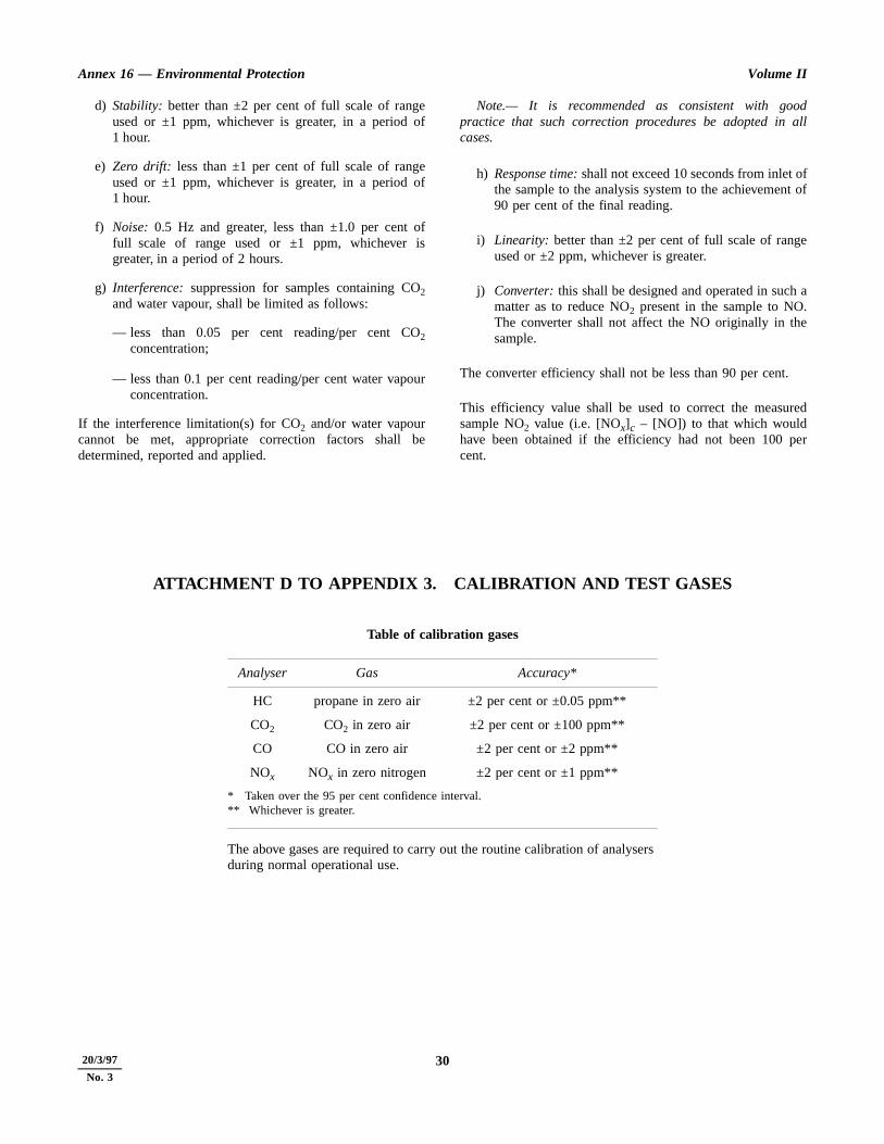
Annex 16 — Environmental Protection Volume II
odall
ft of
e
a.e
red
per
d) Stability: better than ±2 per cent of full scale of rangeused or ±1 ppm, whichever is greater, in a period of1 hour.
e) Zero drift: less than ±1 per cent of full scale of rangeused or ±1 ppm, whichever is greater, in a period of1 hour.
f) Noise: 0.5 Hz and greater, less than ±1.0 per cent offull scale of range used or ±1 ppm, whichever isgreater, in a period of 2 hours.
g) Interference: suppression for samples containing CO2and water vapour, shall be limited as follows:
— less than 0.05 per cent reading/per cent CO2concentration;
— less than 0.1 per cent reading/per cent water vapourconcentration.
If the interference limitation(s) for CO2 and/or water vapourcannot be met, appropriate correction factors shall bedetermined, reported and applied.
Note.— It is recommended as consistent with gopractice that such correction procedures be adopted in cases.
h) Response time: shall not exceed 10 seconds from inlet othe sample to the analysis system to the achievemen90 per cent of the final reading.
i) Linearity: better than ±2 per cent of full scale of rangused or ±2 ppm, whichever is greater.
j) Converter: this shall be designed and operated in suchmatter as to reduce NO2 present in the sample to NOThe converter shall not affect the NO originally in thsample.
The converter efficiency shall not be less than 90 per cent.
This efficiency value shall be used to correct the measusample NO2 value (i.e. [NOx]c – [NO]) to that which wouldhave been obtained if the efficiency had not been 100 cent.
ATTACHMENT D TO APPENDIX 3. CALIBRATION AND TEST GASES
Table of calibration gases
Analyser Gas Accuracy*
HC propane in zero air ±2 per cent or ±0.05 ppm**
CO2 CO2 in zero air ±2 per cent or ±100 ppm**
CO CO in zero air ±2 per cent or ±2 ppm**
NOx NOx in zero nitrogen ±2 per cent or ±1 ppm**
* Taken over the 95 per cent confidence interval.** Whichever is greater.
The above gases are required to carry out the routine calibration of analysers during normal operational use.
3020/3/97
No. 3
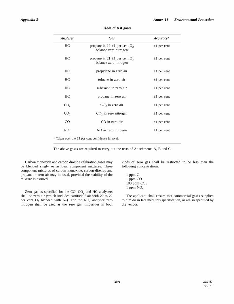
Appendix 3 Annex 16 — Environmental Protection
the
liedby
Table of test gases
Carbon monoxide and carbon dioxide calibration gases maybe blended singly or as dual component mixtures. Threecomponent mixtures of carbon monoxide, carbon dioxide andpropane in zero air may be used, provided the stability of themixture is assured.
Zero gas as specified for the CO, CO2 and HC analysersshall be zero air (which includes “artificial” air with 20 to 22per cent O2 blended with N2). For the NOx analyser zeronitrogen shall be used as the zero gas. Impurities in both
kinds of zero gas shall be restricted to be less than following concentrations:
1 ppm C1 ppm CO100 ppm CO21 ppm NOx
The applicant shall ensure that commercial gases suppto him do in fact meet this specification, or are so specified the vendor.
Analyser Gas Accuracy*
HC propane in 10 ±1 per cent O2balance zero nitrogen
±1 per cent
HC propane in 21 ±1 per cent O2balance zero nitrogen
±1 per cent
HC propylene in zero air ±1 per cent
HC toluene in zero air ±1 per cent
HC n-hexane in zero air ±1 per cent
HC propane in zero air ±1 per cent
CO2 CO2 in zero air ±1 per cent
CO2 CO2 in zero nitrogen ±1 per cent
CO CO in zero air ±1 per cent
NOx NO in zero nitrogen ±1 per cent
* Taken over the 95 per cent confidence interval.
The above gases are required to carry out the tests of Attachments A, B and C.
31 20/3/97
No. 330A

Annex 16 — Environmental Protection Volume II
THIS PAGE INTENTIONALLY LEFT BLANK
3220/3/97
No. 330B

Appendix 3 Annex 16 — Environmental Protection
er
l
le,
e,
e,
e,
ld
ore
ATTACHMENT E TO APPENDIX 3. THE CALCULATION OF THE EMISSIONSPARAMETERS — BASIS, MEASUREMENT CORRECTIONS AND
ALTERNATIVE NUMERICAL METHOD
1. SYMBOLS
AFR air/fuel ratio, the ratio of the mass flow rate of dryair to that of the fuel
EI emission index; 103 × mass flow rate of gaseousemission product in exhaust per unit mass flowrate of fuel
K ratio of concentration measured wet to thatmeasured dry (after cold trap)
L, L′ analyser interference coefficient for interferenceby CO2
M, M′ analyser interference coefficient for interferenceby H2O
MAIR molecular mass of dry air = 28.966 g or, whereappropriate, = (32 R + 28.156 4 S + 44.011 T) g
MCO molecular mass of CO = 28.011 g
MHC molecular mass of exhaust hydrocarbon, taken asCH4 = 16.043 g
MNO2
molecular mass of NO2 = 46.008 g
MC atomic mass of carbon = 12.011 g
MH atomic mass of hydrogen = 1.008 g
P1 number of moles of CO2 in the exhaust sample permole of fuel
P2 number of moles of N2 in the exhaust sample permole of fuel
P3 number of moles of O2 in the exhaust sample permole of fuel
P4 number of moles of H2O in the exhaust sampleper mole of fuel
P5 number of moles of CO in the exhaust sample permole of fuel
P6 number of moles of CxHy in the exhaust sampleper mole of fuel
P7 number of moles of NO2 in the exhaust sampleper mole of fuel
P8 number of moles of NO in the exhaust sample pmole of fuel
PT P1 + P2 + P3 + P4 + P5 + P6 + P7 + P8
R concentration of O2 in dry air, by volume = 0.2095normally
S concentration of N2 + rare gases in dry air, byvolume = 0.7902 normally
T concentration of CO2 in dry air, by volume =0.0003 normally
P0 number of moles of air per mole of fuel in initiaair/fuel mixture
Z symbol used and defined in 3.4
[CO2] mean concentration of CO2 in exhaust sample,vol/vol
[CO] mean concentration of CO in exhaust sampvol/vol
[HC] mean concentration of HC in exhaust samplvol C/vol
[NO] mean concentration of NO in exhaust samplvol/vol
[NO2] mean concentration of NO2 in exhaust sample,vol/vol
[NOx] mean concentration of NO and NO2 in exhaustsample, vol/vol
[NOx]c mean concentration of NO in exhaust samplafter passing through the NO2/NO converter,vol/vol
[NO2] mean =
[ ]d mean concentration in exhaust sample after cotrap, vol/vol
[ ]m mean concentration measurement indicated befinstrument correction applied, vol/vol
NOx[ ]c NO[ ]–( )η
-------------------------------------------
33 20/3/97
No. 331 11/11/93

Annex 16 — Environmental Protection Volume II
buttion
of
esstalthe
)
)
)
5)
6)
7)
)
9)
se notforllyO
ry2.5
the
eO
h humidity of ambient air, vol water/vol dry air
hd humidity of exhaust sample leaving “drier” or“cold trap”, vol water/vol dry sample
m number of C atoms in characteristic fuel molecule
n number of H atoms in characteristic fuel molecule
x number of C atoms in characteristic exhausthydrocarbon molecule
y number of H atoms in characteristic exhausthydrocarbon molecule
η efficiency of NO2/NO converter
2. BASIS OF CALCULATION OF EIAND AFR PARAMETERS
2.1 It is assumed that the balance between the originalfuel and air mixture and the resultant state of the exhaustemissions as sampled can be represented by the followingequation:
CmHn + P0[R(O2) + S(N2) + T(CO2) + h(H2O)]
= P1(CO2) + P2(N2) + P3(O2) + P4(H2O)
+ P5(CO) + P6(CxHy) + P7(NO2) + P8(NO)
from which the required parameters can, by definition, beexpressed as
EI(CO) = P5
EI(HC) = xP6 expressed as methane equivalent
EI(NOx) = (P7 + P8) expressed as NO2 equivalent
AFR = P0
2.2 Values for fuel hydrocarbon composition (m, n) areassigned by fuel specification or analysis. If only the ratio
n/m is so determined, the value m = 12 may be assigned. Themole fractions of the dry air constituents (R, S, T) arenormally taken to be the recommended standard values alternative values may be assigned, subject to the restricR+ S + T = 1 and the approval of the certificating authority.
2.3 The ambient air humidity, h, is as measured at eachtest condition. It is recommended that, in the absencecontrary evidence as to the characterization (x, y) of theexhaust hydrocarbon, values of x = 1 and y = 4 are assigned.
2.4 Determination of the remaining unknowns requirthe solution of the following set of linear simultaneouequations, where (1) to (4) derive from the fundamenatomic conservation relationships and (5) to (9) represent gaseous product concentration relationships.
m + TP0 = P1 + P5 + xP6 . . . . . . . . . . . . . . . . . . . . . . . (1
n + 2hP0 = 2P4 + yP6 . . . . . . . . . . . . . . . . . . . . . . . . . . (2
(2R + 2T + h)P0= 2P1 + 2P3 + P4 + P5+ 2P7 + P8 . . . . . . . . . . . . . . . (3)
2SP0 = 2P2 + P7 + P8 . . . . . . . . . . . . . . . . . . . . . . . . . . (4
[CO2] PT = P1 . . . . . . . . . . . . . . . . . . . . . . . . . . . . . . . . (
[CO] PT = P5 . . . . . . . . . . . . . . . . . . . . . . . . . . . . . . . . . (
[HC] PT = xP6 . . . . . . . . . . . . . . . . . . . . . . . . . . . . . . . . (
[NOx] cPT= η P7 + P8 . . . . . . . . . . . . . . . . . . . . . . . . . . (8
[NO] PT = P8 . . . . . . . . . . . . . . . . . . . . . . . . . . . . . . . . . (
PT = P1 + P2 + P3 + P4 + P5 + P6 + P7 + P8 . . . . . . (10)
The above set of conditional equations is for the cawhere all measured concentrations are true ones, that is,subject to interference effects or to the need to correct sample drying. In practice, interference effects are usuapresent to a significant degree in the CO, and Nmeasurements, and the option to measure CO2 and CO on adry or partially dry basis is often used. The necessamodifications to the relevant equations are described in and 2.6.
2.5 The interference effects are mainly caused by presence of CO2 and H2O in the sample which can affect theCO and the NOx analysers in basically different ways. ThCO analyser is prone to a zero-shifting effect and the Nxanalyser to a sensitivity change, represented thus:
[CO] = [CO]m + L[CO2] + M[H2O]
and [NOx]c = [NOx]cm (1 + L′[CO2] + M′[H2O])
103MCO
mMC nMH+-------------------------------
103MHC
mMC nMH+-------------------------------
103MNO2
mMC nMH+-------------------------------
MAIR
mMC nMH+-------------------------------
3420/3/97
No. 33211/11/93 32
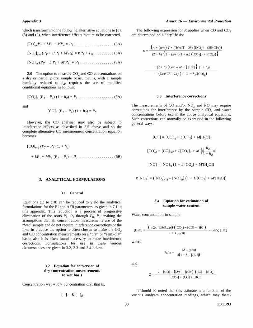
Appendix 3 Annex 16 — Environmental Protection
ns.ing
hem-
which transform into the following alternative equations to (6),(8) and (9), when interference effects require to be corrected,
[CO]mPT + LP1 + MP4 = P5 . . . . . . . . . . . . . . . . . . . . (6A)
[NOx]cm (PT + L′P1 + M′P4) = ηP7 + P8 . . . . . . . . . . (8A)
[NO]m (PT + L′P1 + M′P4) = P8 . . . . . . . . . . . . . . . . . (9A)
2.6 The option to measure CO2 and CO concentrations ona dry or partially dry sample basis, that is, with a samplehumidity reduced to hd, requires the use of modifiedconditional equations as follows:
[CO2]d (PT – P4) (1 + hd) = P1 . . . . . . . . . . . . . . . . . . (5A)
and[CO]d (PT – P4) (1 + hd) = P5
However, the CO analyser may also be subject tointerference effects as described in 2.5 above and so thecomplete alternative CO measurement concentration equationbecomes
[CO]md (PT – P4) (1 + hd)
+ LP1 + Mhd (PT – P4) = P5 . . . . . . . . . . . . . . . . . . (6B)
3. ANALYTICAL FORMULATIONS
3.1 General
Equations (1) to (10) can be reduced to yield the analyticalformulations for the EI and AFR parameters, as given in 7.1 tothis appendix. This reduction is a process of progressiveelimination of the roots P0, P1 through P8, PT, making theassumptions that all concentration measurements are of the“wet” sample and do not require interference corrections or thelike. In practice the option is often chosen to make the CO2and CO concentration measurements on a “dry” or “semi-dry”basis; also it is often found necessary to make interferencecorrections. Formulations for use in these variouscircumstances are given in 3.2, 3.3 and 3.4 below.
3.2 Equation for conversion ofdry concentration measurements
to wet basis
Concentration wet = K × concentration dry; that is,
[ ] = K [ ]d
The following expression for K applies when CO and CO2are determined on a “dry” basis:
3.3 Interference corrections
The measurements of CO and/or NOx and NO may requirecorrections for interference by the sample CO2 and waterconcentrations before use in the above analytical equatioSuch corrections can normally be expressed in the followgeneral ways:
[CO] = [CO]m + L[CO2] + M[H2O]
[CO]d = [CO]md + L[CO2]d + M
[NO] = [NO]m (1 + L′[CO2] + M′[H2O])
η[NO2] = ([NOx]cm – [NO]m) (1 + L′[CO2] + M′[H2O])
3.4 Equation for estimation ofsample water content
Water concentration in sample
where
and
It should be noted that this estimate is a function of tvarious analyses concentration readings, which may the
K = { 4 + (n/m) T + (n/mT – 2h) ([NO2] – (2[HC]/x))
(2 + h) { 2 + (n/m) (1 + hd) ([CO2]d + [CO]d)}
+ (2 + h) (y/x–n/m) [HC]} (1 + hd)
– (n/mΤ – 2h) (1 –1 + hd [CO]d)
[H2O] =(|n/2m| + h|P0/m|) ([CO2] + [CO] + [HC])
– (y/2x) [HC]1 + T(P0/m)
P0/m =2Z – (n/m)
4(1 + h – |TZ/2|)
Z = 2 – [CO] – (|2/x| – |y/2x|) [HC] + [NO2]
[CO2] + [CO] + [HC]
hd
1 hd+--------------
35 20/3/97
No. 33333 11/11/93

Annex 16 — Environmental Protection Volume II
ch
ionthelarons
n-eirdys
ine
±1heh
an
ofce
atbeiod
selves require water interference correction. For betteraccuracy an iterative procedure is required in these cases withsuccessive recalculation of the water concentration until therequisite stability is obtained. The use of the alternative,numerical solution methodology (4) avoids this difficulty.
4. ALTERNATIVE METHODOLOGY —NUMERICAL SOLUTION
4.1 As an alternative to the analytical proceduressummarized in 3 above, it is possible to obtain readily theemissions indices, fuel/air ratio, corrected wet concentrations,
etc., by a numerical solution of equations (1) to (10) for easet of measurements, using a digital computer.
4.2 In the equation set (1) to (10) the actual concentratmeasurements are substituted using whichever of alternative equations (5A), (6A), etc. applies for the particumeasuring system, to take account of interference correctiand/or dried sample measurements.
4.3 Suitable simple two-dimensional array equatiosolving computer programmes are widely available and thuse for this purpose is convenient and flexible, allowing reaincorporation and identification of any sample drying optionand interference or other corrections.
ATTACHMENT F TO APPENDIX 3. SPECIFICATIONS FORADDITIONAL DATA
As required in 3.2 of Appendix 3, in addition to the measuredsample constituent concentrations, the following data shallalso be provided:
a) inlet temperature: measured as the total temperature at apoint within one diameter of the engine intake plane toan accuracy of ±0.5°C;
b) inlet humidity (kg water/kg dry air): measured at a pointwithin 15 m of the intake plane ahead of the engine toan accuracy of ±5 per cent of reading;
c) atmospheric pressure: measured within 1 km of theengine test location and corrected as necessary to thetest stand altitude to an accuracy of ±100 Pa;
d) fuel mass flow: by direct measurement to an accuracy of±2 per cent;
e) fuel H/C ratio: defined as n/m, where CmHn is theequivalent hydrocarbon representation of the fuel used
in the test and evaluated by reference to the engfuel type analysis;
f) engine parameters:
1) thrust: by direct measurement to an accuracy of per cent at take-off power and ±5 per cent at tminimum thrust used in the certification test, witlinear variation between these points;
2) rotation speed(s): by direct measurement to accuracy of at least ±0.5 per cent;
3) gas generator airflow: determined to an accuracy±2 per cent by reference to engine performancalibration.
The parameters a), b), d) and f) shall be determinedeach engine emissions test setting, while c) shall determined at intervals of not less than 1 hour over a perencompassing that of the emissions tests.
3620/3/97
No. 33411/11/93 34

ANNEX 16 — VOLUME II 35 11/11/93
APPENDIX 4. SPECIFICATION FOR FUEL TO BE USED INAIRCRAFT TURBINE ENGINE EMISSION TESTING
PropertyAllowable range
of values
Density kg/m3 at 15°C 780 – 820Distillation temperature, °C
10% boiling point 155 – 201Final boiling point 235 – 285
Net heat of combustion, MJ/kg 42.86 – 43.50Aromatics, volume % 15 – 23Naphthalenes, volume % 1.0 – 3.5Smoke point, mm 20 – 28Hydrogen, mass % 13.4 – 14.1Sulphur, mass % less than 0.3%Kinematic viscosity at –20°C, mm2/s 2.5 – 6.5
ific
h
- as toheple,pm
y
nent the
nterment
ch
atput
ntsven
the
no
APPENDIX 5. INSTRUMENTATION AND MEASUREMENT TECHNIQUESFOR GASEOUS EMISSIONS FROM
AFTERBURNING GAS TURBINE ENGINES
1. INTRODUCTION
Note.— The procedures specified in this appendix areconcerned with the acquisition of representative exhaustsamples and their transmission to, and analysis by, theemissions measuring system. These procedures only applywhen afterburning is employed. The methods proposed arerepresentative of the best readily available and mostestablished modern practice. The need to correct for ambientconditions is recognized and a method will be specified whenone becomes available. Meanwhile any correction methodsused when afterburning is employed should be approved by thecertificating authority.
Variations in the procedure contained in this appendix shallonly be allowed after prior application to and approval by thecertificating authority.
2. DEFINITIONS
Where the following expressions are used without furtherexplanation in this appendix, they have the meanings ascribedto them below:
Accuracy. The closeness with which a measurementapproaches the true value established independently.
Calibration gas. A high accuracy reference gas to be usedfor alignment, adjustment and periodic checks of instruments.
Concentration. The volume fraction of the component ofinterest in the gas mixture — expressed as volume percentageor as parts per million.
Flame ionization detector. A hydrogen-air diffusion flamedetector that produces a signal nominally proportional to themass-flow rate of hydrocarbons entering the flame per unit oftime — generally assumed responsive to the number of carbonatoms entering the flame.
Interference. Instrument response due to presence ofcomponents other than the gas (or vapour) that is to bemeasured.
Noise. Random variation in instrument output notassociated with characteristics of the sample to which theinstrument is responding, and distinguishable from its driftcharacteristics.
Non-dispersive infra-red analyser. An instrument that byabsorption of infra-red energy selectively measures speccomponents.
Parts per million (ppm). The unit volume concentrationof a gas per million unit volume of the gas mixture of whicit is a part.
Parts per million carbon (ppmC). The mole fraction ofhydrocarbon multiplied by 106 measured on a methaneequivalence basis. Thus, 1 ppm of methane is indicated1 ppmC. To convert ppm concentration of any hydrocarbonan equivalent ppmC value, multiply ppm concentration by tnumber of carbon atoms per molecule of the gas. For exam1 ppm propane translates as 3 ppmC hydrocarbon; 1 phexane as 6 ppmC hydrocarbon.
Plume. Total external engine exhaust flow, including anambient air with which the exhaust mixes.
Reference gas. A mixture of gases of specified and knowcomposition used as the basis for interpreting instrumresponse in terms of the concentration of the gas to whichinstrument is responding.
Repeatability. The closeness with which a measuremeupon a given, invariant sample can be reproduced in short-trepetitions of the measurement with no intervening instrumadjustment.
Resolution. The smallest change in a measurement whican be detected.
Response. The change in instrument output signal thoccurs with change in sample concentration. Also the outsignal corresponding to a given sample concentration.
Stability. The closeness with which repeated measuremeupon a given invariant sample can be maintained over a giperiod of time.
Zero drift. Time-related deviation of instrument outpufrom zero set point when it is operating on gas free of tcomponent to be measured.
Zero gas. A gas to be used in establishing the zero, or response, adjustment of an instrument.
11/11/93 36 ANNEX 16 — VOLUME II

Appendix 5 Annex 16 — Environmental Protection
37 11/11/93
Figure 5-1. Exhaust gas sampling system, schematic
EX H AU S TN O Z ZLE
M in im um o f 4nozz le diam ete rs
18 - 25 nozz le d iam ete rs
N O Z ZLE C EN T R E L IN EPR O B E
SA M P LET R AN S FE RLIN E
N O Z ZLEEX IT P LAN E
SA M P LIN GPLA N E
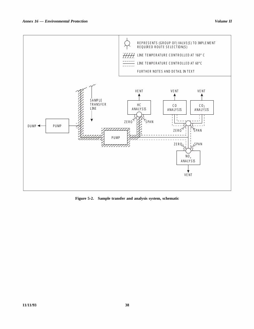
Annex 16 — Environmental Protection Volume II
11/11/93 38
Figure 5-2. Sample transfer and analysis system, schematic
SA M P LET R AN S FE RL IN E
PU M PD U M P
PU M P
Z E R O SPA N
VE N T VE N T VE N T
H CAN A LY SIS
C OAN A LY SIS
C O 2AN A LY SIS
Z E R O
Z E R O
SPA N
SPA N
N OAN A LY SIS
x
VE N T
R EP R ES E N T S (G R O U P O F) VA LV E(S) TO IM PLE M E N TR EQ U IR ED R O U T E SE LE C T IO N (S)
L IN E T EM PE R ATU R E C O N T R O LL ED AT 16 0° C
L IN E T EM PE R ATU R E C O N T R O LL ED AT 60 ° C
F U RT H E R N O TE S A N D D E TA IL IN T EX T

Appendix 5 Annex 16 — Environmental Protection
onuslist
b-di-
ille
nts.ngesene
sFornd of
of the
eure- be
lesr of
beat a
ro- as thesexitdi-eszleine
3. DATA REQUIRED
3.1 Gaseous emissions
Concentrations of the following emissions shall be determined:
a) Hydrocarbons (HC): a combined estimate of allhydrocarbon compounds present in the exhaust gas.
b) Carbon monoxide (CO).
c) Carbon dioxide (CO2).
Note.— CO2 is not considered a pollutant but itsconcentration is required for calculation and checkpurposes.
d) Oxides of nitrogen (NOx): an estimate of the sum of thetwo oxides, nitric oxide (NO) and nitrogen dioxide(NO2).
e) Nitric oxide (NO).
3.2 Other information
In order to normalize the emissions measurement data and toquantify the engine test characteristics, other information inaddition to the requirements of Chapter 3, 3.4 shall beprovided as follows:
— inlet temperature;— inlet humidity;— atmospheric pressure;— wind vectors relative to engine exhaust axis;— hydrogen/carbon ratio of fuel;— engine installation details;— other required engine parameters (for example, thrust,
rotor speeds, turbine temperatures);— pollutant concentration data and statistical validation
parameters.
This data shall be obtained either by direct measurement or bycalculation, as presented in Attachment F to this appendix.
4. GENERAL ARRANGEMENTOF THE SYSTEM
Owing to the reactive nature of the exhaust plume fromengines using afterburning, it is necessary to ensure that themeasured emissions do in fact correspond to those actuallyemitted into the surrounding atmosphere. This is achieved bysampling the plume sufficiently far downstream from theengine that the exhaust gases have cooled to a temperaturewhere reactions have ceased. No desiccants, dryers, watertraps or related equipment shall be used to treat the exhaust
sample flowing to the oxides of nitrogen and the hydrocarbanalysis instrumentation. Requirements for the variocomponent sub-systems are given in 5, but the following gives some qualifications and variations:
a) it is assumed that each of the various individual susystems includes the necessary flow control, contioning and measurement facilities;
b) the necessity for a dump and/or a hot-sample pump wdepend on the ability to meet the sample transfer timand analysis sub-system sample flow rate requiremeThis in turn depends on the exhaust sample-drivipressure and line losses. It is considered that thpumps usually will be necessary at certain engirunning conditions; and
c) the position of the hot pump, relative to the gaanalysis sub-systems, may be varied as required. (example, some HC analysers contain hot pumps aso may be judged capable of being used upstreamthe system hot pump.)
Note.— Figures 5-1 and 5-2 are schematic drawings the exhaust gas sampling and analytical system and typifybasic requirements for emissions testing.
5. DESCRIPTION OFCOMPONENT PARTS
Note.— A general description and specification of thprincipal elements in the engine exhaust emissions measment system follows. Greater detail, where necessary, willfound in Attachments A, B and C to this appendix.
5.1 Sampling system
5.1.1 Sampling probe
a) The probe shall be constructed so that individual sampcan be withdrawn at various locations across a diametethe plume. Mixed samples shall not be permitted.
b) The material with which the sample is in contact shall stainless steel and its temperature shall be maintained value not less than 60°C.
c) The sampling plane shall be perpendicular to the pjected engine nozzle centre line, and shall be situatedclose as possible to a position 18 nozzle diameters fromnozzle exit plane, consistent with 7.1.2, but in no cagreater than 25 nozzle diameters. The nozzle ediameter shall be for the maximum engine power contion. Between and including exit and sampling planthere shall be an unobstructed region of at least 4 nozexit diameters in radial distance about the project engnozzle centre line.
39 11/11/93
Annex 16 — Environmental Protection Volume II
thehehe.
terantw,
eroks.
C
ilitycyntseibed at
nt
ghustofhall
ofO
g.
to
glid
d) The minimum number of sampling points shall be equalto 11. The measurement plane, located at a distance Xfrom the engine shall be divided into three sectionsdemarcated by circles centred around the exhaust streamaxis with radii
R1 = 0.05XR2 = 0.09X
and a minimum of 3 samples shall be taken from eachsection. The difference between the number of samples ineach section must be less than 3. The sample taken at themost remote distance from the axis shall be from a pointlocated at a radius of between 0.11X and 0.16X.
5.1.2 Sampling lines
The sample shall be transferred from the probe to the analysersvia a line of 4.0 to 8.5 mm inside diameter, taking the shortestroute practicable and using a flow rate such that the transporttime is less than 10 seconds. The line shall be maintained at atemperature of 160°C ±15°C (with a stability of ±10°C). Whensampling to measure HC, CO, CO2 and NOx components, theline shall be constructed in stainless steel or carbon-loadedgrounded PTFE.
5.2 HC analyser
The measurement of total hydrocarbon sample content shall bemade by an analyser using the heated flame ionization detector(FID), between the electrodes of which passes an ionizationcurrent proportional to the mass rate of hydrocarbon enteringa hydrogen flame. The analyser shall be deemed to includecomponents arranged to control temperature and flow rates ofsample, sample bypass, fuel and diluent gases, and to enableeffective span and zero calibration checks.
Note.— An over-all specification is given in Attachment Ato this appendix.
5.3 CO and CO2 analysers
Non-dispersive infra-red analysers shall be used for themeasurement of these components, and shall be of the designwhich utilizes differential energy absorption in parallelreference and sample gas cells, the cell or group of cells foreach of these gas constituents being sensitized appropriately.This analysis sub-system shall include all necessary functionsfor the control and handling of sample, zero and span gasflows. Temperature control shall be that appropriate towhichever basis of measurement, wet or dry, is chosen.
Note.— An over-all specification is given in Attachment Bto this appendix.
5.4 NOx analyser
The measurement of NO concentration shall be by chemiluminescent method in which the measure of tradiation intensity emitted during the reaction of the NO in tsample with added O3 is the measure of the NO concentrationThe NO2 component shall be converted to NO in a converof the requisite efficiency prior to measurement. The resultNOx measurement system shall include all necessary flotemperature and other controls and provide for routine zand span calibration as well as for converter efficiency chec
Note.— An over-all specification is given in Attachmentto this appendix.
6. GENERAL TEST PROCEDURES
6.1 Engine operation
The engine shall be operated on an open air static test facwhich is suitable and properly equipped for high accuraperformance testing, and which conforms to the requiremefor sampling probe installation as specified in 5.1. Themissions tests shall be made at the power settings prescrby the certificating authority. The engine shall be stabilizedeach setting.
6.2 Ambient air conditions
6.2.1 A check shall be made on the ambieconcentrations of CO, HC, CO2 and NOx , with the engineunder test running at the test condition. Unusually hiconcentrations indicate abnormal conditions such as exhagas recirculation, fuel spillage or some other source unwanted emissions in the test area and such situations sbe rectified or avoided as appropriate.
Note.— For guidance, the normal ambient concentrationCO2 is 0.03 per cent, and ambient concentration levels for Cand HC of 5 ppm and NOx of 0.5 ppm are unlikely to beexceeded under normal conditions.
6.2.2 Extreme climatic conditions, such a those involvinprecipitation or excessive wind speed shall also be avoided
6.3 Major instrument calibration
Note.— The general objective of this calibration is confirm stability and linearity.
6.3.1 The applicant shall satisfy the certificatinauthority that the calibration of the analytical system is vaat the time of the test.
11/11/93 40
Appendix 5 Annex 16 — Environmental Protection
h
ngnethat
irer
en
or
ary
erjust
sitetoad.
heing
teststs.ulltion
ionsinghesicrted,
.
6.3.2 For the hydrocarbon analyser this calibration shallinclude checks that the detector oxygen and differentialhydrocarbon responses are within the limits specified inAttachment A to this appendix. The efficiency of the NO2/NOconverter shall also be checked and verified to meet therequirements in Attachment C to this appendix.
6.3.3 The procedure for checking the performance of eachanalyser shall be as follows (using the calibration and testgases as specified in Attachment D to this appendix):
a) introduce zero gas and adjust instrument zero, recordingsetting as appropriate;
b) for each range to be used operationally, introducecalibration gas of (nominally) 90 per cent range full-scale deflection (FSD) concentration; adjust instrumentgain accordingly and record its setting;
c) introduce approximately 30 per cent, 60 per cent, and 90per cent range FSD concentrations and record analyserreadings;
d) fit a least squares straight line to the zero, 30 percent, 60 per cent and 90 per cent concentration points.For the CO and/or CO2 analyser used in its basic formwithout linearization of output, a least squares curveof appropriate mathematical formulation shall be fittedusing additional calibration points if judged necessary.If any point deviates by more than 2 per cent of thefull scale value (or ±1 ppm*, whichever is greater)then a calibration curve shall be prepared foroperational use.
6.4 Operation
6.4.1 No measurements shall be made until allinstruments and sample transfer lines are warmed up andstable and the following checks have been carried out:
a) leakage check: prior to a series of tests the systemshall be checked for leakage by isolating the probeand the analysers, connecting and operating a vacuumpump of equivalent performance to that used in thesmoke measurement system to verify that the systemleakage flow rate is less than 0.4 L/min referred tonormal temperature and pressure;
b) cleanliness check: isolate the gas sampling systemfrom the probe and connect the end of the samplingline to a source of zero gas. Warm the system up tothe operational temperature needed to perform hydro-carbon measurements. Operate the sample flow pumpand set the flow rate to that used during engineemission testing. Record the hydrocarbon analyserreading. The reading shall not exceed 1 per cent of
the engine idle emission level or 1 ppm (botexpressed as methane), whichever is the greater.
Note 1.— It is good practice to back-purge the samplilines during engine running, while the probe is in the engiexhaust but emissions are not being measured, to ensure no significant contamination occurs.
Note. 2.— It is also good practice to monitor the inlet aquality at the start and end of testing and at least once phour during a test. If levels are considered significant, ththey should be taken into account.
6.4.2 The following procedure shall be adopted foperational measurements:
a) apply appropriate zero gas and make any necessinstrument adjustments;
b) apply appropriate calibration gas at a nominal 90 pcent FSD concentration for the ranges to be used, adand record gain settings accordingly;
c) when the engine has been stabilized at the requioperating conditions and sampling location, continue run it and observe pollutant concentrations until stabilized reading is obtained, which shall be recordeAt the same engine operating condition repeat tmeasurement procedure for each of the remainsampling locations;
d) recheck zero and calibration points at the end of the and also at intervals not greater than 1 hour during teIf either has changed by more than ±2 per cent of fscale of range, the test shall be repeated after restoraof the instrument to within its specification.
7. CALCULATIONS
7.1 Gaseous emissions
7.1.1 General
The analytical measurements made shall be the concentratof the various classes of pollutant, at the relevant afterburnmode(s) of the engine, at the various locations in tsampling plane. In addition to the recording of these baparameters, other parameters shall be computed and repoas follows.
* Except for the CO2 analyser, for which the value shall be ±100 ppm
41 11/11/93

Annex 16 — Environmental Protection Volume II
en
ns
e,
7.1.2 Analysis and validationof measurements
a) At each engine setting, the concentrations measured atdifferent probe sampling positions must be averaged asfollows:
where
Summation of the total number n of samplingpositions used.
Cij Concentration of species i measured at the jthsampling position.
Ci moy average or mean concentration of species i.
All dry concentration measurements shall be converted intoreal wet concentrations. (See Attachment E to thisappendix).
b) The quality of the measurements for each pollutant will bedetermined through a comparison with measurements ofCO2 using the correlation coefficient:
Values of ri which are near to 1 indicate that measurementstaken over the entire sampling period are sufficiently stableand that the curves are gaussian. In the event that ri is lessthan 0.95, measurements must be repeated in a samplingplane located at a more remote distance from the aircraftengine. The measurement process, per se, is then followedby the same calculations and the same demonstration aspreviously.
7.1.3 Basic parameters
For the measurements at each engine operating mode theaverage concentration for each gaseous species is estimated asshown in 7.1.2, any necessary corrections for dry samplemeasurement and/or interferences having been made asindicated in Attachment E to this appendix. These averageconcentrations are used to compute the following basicparameters:
EI(CO) = (1 + T(P0/m))
EI(HC) = (1 + T(P0/m))
(1 + T(P0/m))
Air/fuel ratio = (P0/m)
where
and
MAIR molecular mass of dry air = 28.966 gor, where appropriate,= (32 R + 28.156 4 S + 44.011 T) g
MHC molecular mass of exhaust hydrocarbons, takas CH4 = 16.043 g
MCO molecular mass of CO = 28.011 g
MNO2
molecular mass of NO2 = 46.088 g
MC atomic mass of carbon = 12.011 g
MH atomic mass of hydrogen = 1.008 g
R concentration of O2 in dry air, by volume =0.209 5 normally
S concentration of N2 + rare gases in dry air, byvolume = 0.709 2 normally
T concentration of CO2 in dry air, by volume =0.000 3 normally
[HC] mean concentration of exhaust hydrocarbovol/vol, wet, expressed as carbon
[CO] mean concentration of CO vol/vol, wet
[CO2] mean concentration of CO2 vol/vol, wet
[NOx] mean concentration of NOx vol/vol, wet =[NO + NO2]
[NO] mean concentration of NO in exhaust samplvol/vol, wet
EIp (emission index=
mass of p produced in g
for component p) mass of fuel used in kg
Ci moy Ci jj 1=
n
∑=
j 1=
n
∑
r i
n Ci j CO2 j Ci j CO2jj 1=
n∑
j 1=
n∑–
j 1=
n∑
n CO2j( ) CO2jj 1=
n∑
2
–2
j 1=
n∑
n Cij 2 Ci jj 1=
n∑
2
–j 1=
n∑
---------------------------------------------------------------------------------------------------------------------------------------------------------------=
√
P0/m =2Z – (n/m)
4(1 + h – TZ/2)
Z = 2 – [CO] – (|2/x| – |y/2x|) [HC} + [NO2]
[CO2] + [CO] + [HC]
CO[ ]CO2[ ] CO[ ] HC[ ]+ +
-------------------------------------------------------- 10
3MCO
MC n m⁄( )MH+----------------------------------------
HC[ ]CO2[ ] CO[ ] HC[ ]+ +
--------------------------------------------------------
103MHC
MC n m⁄( )MH+----------------------------------------
NOx[ ]CO2[ ] CO[ ] HC[ ]+ +
-------------------------------------------------------- 10
3MNO2
MC n m⁄( )MH+----------------------------------------
MAIR
MC n m⁄( )MH+---------------------------------------
EI(NOx)(as NO2)
=
11/11/93 42
Appendix 5 Annex 16 — Environmental Protection
neised
Aoreisith
aeed
h
be by
ere
COhed
[NO2] mean concentration of NO2 in exhaust sample,vol/vol, wet
=
[NOx]c mean concentration of NO in exhaust sampleafter passing through the NO2/NO converter,vol/vol, wet
η efficiency of NO2/NO converter
h humidity of ambient air, vol water/vol dry air
m number of C atoms in characteristic fuelmolecule
n number of H atoms in characteristic fuelmolecule
x number of C atoms in characteristic exhausthydrocarbon molecule
y number of H atoms in characteristic exhausthydrocarbon molecule
The value of n/m, the ratio of the atomic hydrogen to atomiccarbon of fuel used, is evaluated by fuel type analysis. Theambient air humidity, h, shall be measured at each setcondition. In the absence of contrary evidence as to thecharacterization (x,y) of the exhaust hydrocarbons, the valuesx = 1, y = 4 are to be used. If dry or semi-dry CO and CO2measurements are to be used then these shall first be con-verted to the equivalent wet concentrations as shown inAttachment E to this appendix, which also contains inter-ference correction formulas for use as required.
Note.— The procedure given in 7.1.4 and 7.2 is onlyapplicable to tests made when afterburning is not used. Fortests when afterburning is used, a similar procedure could beused after approval by the certificating authority.
7.1.4 Correction of emission indicesto reference conditions
Corrections shall be made to the measured engine emissionindices for all pollutants in all relevant engine operatingmodes to account for deviations from the reference conditions(ISA at sea level) of the actual test inlet air conditions oftemperature and pressure. The reference value for humidityshall be 0.006 29 kg water/kg dry air.
Thus, EI corrected = K × EI measured,
where the generalized expression for K is:
K = (PBref/PB)a × (FARref/FARB)b
× exp (|TBref – TB|/c) × exp (d|h – 0.006 29|)
PB Combustor inlet pressure, measured
TB Combustor inlet temperature, measured
FARB Fuel/air ratio in the combustor
h Ambient air humidity
Pref ISA sea level pressure
Tref ISA sea level temperature
PBref Pressure at the combustor inlet of the engitested (or the reference engine if the data corrected to a reference engine) associatwith TB under ISA sea level conditions.
TBref Temperature at the combustor inlet under ISsea level conditions for the engine tested (the reference engine if the data is to bcorrected to a reference engine). Thtemperature is the temperature associated weach thrust level specified for each mode.
FARref Fuel/air ratio in the combustor under ISA selevel conditions for the engine tested (or threference engine if the data is to be correctto a reference engine).
a,b,c,d Specific constants which may vary for eacpollutant and each engine type.
The combustor inlet parameters shall preferably measured but may be calculated from ambient conditionsappropriate formulas.
7.1.5 Using the recommended curve fitting techniquto relate emission indices to combustor inlet temperatueffectively eliminates the exp (|TBref – TB|/c) term from thegeneralized equation and for most cases the (FARref /FARB)term may be considered unity. For the emissions indices of and HC many testing facilities have determined that thumidity term is sufficiently close to unity to be eliminatefrom the expression and that the exponent of the (PBref /PB)term is close to unity.
Thus,
EI(CO) corrected = EI derived from(PB /PBref) " EI(CO) v. TB curve
EI(HC) corrected = EI derived from(PB /PBref) " EI(HC) v. TB curve
NOx[ ]c NO[ ]–( )η
-------------------------------------------
43 11/11/93
Annex 16 — Environmental Protection Volume II
gub-
ient
ofnce
al
e
tio
he
heepted ifurve
therofgedive
EI(NOx) corrected = EI derived from EI(NOx) (PBref /PB)0.5 exp (19 |h – 0.006 29 | ) v. TB curve
If this recommended method for the CO and HC emissionsindex correction does not provide a satisfactory correlation, analternative method using parameters derived from componenttests may be used.
Any other methods used for making corrections to CO, HCand NOx emissions indices shall have the approval of thecertificating authority.
7.2 Control parameter functions(Dp, Foo, π)
7.2.1 Definitions
Dp The mass of any gaseous pollutant emitted during thereference emissions landing and take-off cycle.
Foo The maximum thrust available for take-off undernormal operating conditions at ISA sea level staticconditions, without the use of water injection, asapproved by the applicable certificating authority.
π The ratio of the mean total pressure at the lastcompressor discharge plane of the compressor to themean total pressure at the compressor entry planewhen the engine is developing take-off thrust ratingat ISA sea level static conditions.
7.2.2 The emission indices (EI) for each pollutant,corrected for pressure and humidity (as appropriate) to thereference ambient atmospheric conditions as indicated in 7.1.4and if necessary to the reference engine, shall be obtained forthe required LTO engine operating mode settings (n) of idle,approach, climb-out and take-off, at each of the equivalentcorrected thrust conditions. A minimum of three test pointsshall be required to define the idle mode. The followingrelationships shall be determined for each pollutant:
a) between EI and TB ; and
b) between Wf (engine fuel mass flow rate) and TB ; and
c) between Fn (corrected to ISA sea level conditions) andTB (corrected to ISA sea level conditions);
Note.— These are illustrated, for example, by Figure 5-3 a),b) and c).
When the engine being tested is not a “reference” engine,the data may be corrected to “reference” engine conditionsusing the relationships b) and c) obtained from a referenceengine. A reference engine is defined as an engine substan-tially configured to the description of the engine to be certifi-cated and accepted by the certificating authority to be repre-sentative of the engine type for which certification is sought.
The manufacturer shall also supply to the certificatinauthority all of the necessary engine performance data to sstantiate these relationships and for ISA sea level ambconditions:
d) maximum rated thrust (Foo); and
e) engine pressure ratio (π) at maximum rated thrust.
Note.— These are illustrated by Figure 5-3 d).
7.2.3 The estimation of EI for each pollutant at each the required engine mode settings, corrected to the refereambient conditions, shall comply with the following generprocedure:
a) at each mode ISA thrust condition Fn, determine theequivalent combustor inlet temperature (TB) (Figure5-3 c));
b) from the EI/TB characteristic (Figure 5-3 a)), determinthe EIn value corresponding to TB;
c) from the Wf /TB characteristics (Figure 5-3 b)),determine the Wfn
value corresponding to TB;
d) note the ISA maximum rated thrust and pressure ravalues. These are Foo and π respectively (Figure 5-3 d));
e) calculate, for each pollutant Dp = Σ (EIn) (Wfn) (t)
where:
t time in LTO mode (minutes)
Wfn
fuel mass flow rate (kg/min)
Σ is the summation for the set of modes comprising treference LTO cycle.
7.2.4 While the methodology described above is trecommended method, the certificating authority may accequivalent mathematical procedures which utilizmathematical expressions representing the curves illustratethe expressions have been derived using an accepted cfitting technique.
7.3 Exceptions to theproposed procedures
In those cases where the configuration of the engine or oextenuating conditions exist which would prohibit the use this procedure, the certificating authority, after receivinsatisfactory technical evidence of equivalent results obtainby an alternative procedure, may approve an alternatprocedure.
11/11/93 44
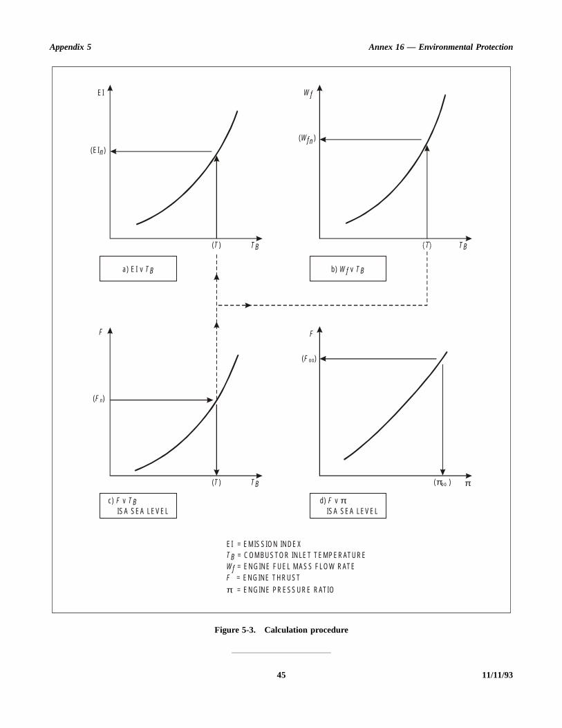
Appendix 5 Annex 16 — Environmental Protection
45 11/11/93
Figure 5-3. Calculation procedure
a) E I v T B b) v W f T B
c) v F T B d) v F πIS A SEA LEV EL IS A SEA LEV EL
( )o oπ π
F
( )F o o
F
( )F n
( )T
( )T
TB
TB
EI
(E I )n
W f
( )Wf n
TB
EI = EM IS SIO N IN D E X = C OM BU S TO R IN LE T T EM P ER ATU R E = EN G IN E F U EL M AS S F LO W R ATE
= EN G IN E T H R U ST
= EN G IN E PR ESS U R E R ATIO
T BWfF
π
te
arse
ce
ofed
aonC,of
be
of to
en
ta
ATTACHMENT A TO APPENDIX 5. SPECIFICATIONFOR HC ANALYSER
Note 1.— As outlined in 5.2 of Appendix 5, the measuringelement in this analyser is the flame ionization detector (FID)in which the whole or a representative portion of the sampleflow is admitted into a hydrogen-fuelled flame. With suitablypositioned electrodes an ionization current can be establishedwhich is a function of the mass rate of hydrocarbon enteringthe flame. It is this current which, referred to an appropriatezero, is amplified and ranged to provide the output response asa measure of the hydrocarbon concentration expressed asppmC equivalent.
Note 2.— See Attachment D for information on calibrationand test gases.
1. GENERAL
Precautions: The performance specifications indicated aregenerally for analyser full scale. Errors at part scale may be asignificantly greater percentage of reading. The relevance andimportance of such increases shall be considered whenpreparing to make measurements. If better performance isnecessary, then appropriate precautions shall be taken.
The instrument to be used shall be such as to maintain thetemperature of the detector and sample-handling componentsat a set point temperature within the range 155°C to 165°C toa stability of ±2°C. The leading specification points shall be asfollows, the detector response having been optimized and theinstrument generally having stabilized:
a) Total range: 0 to 500 ppmC in appropriate ranges.
b) Resolution: better than 0.5 per cent of full scale of rangeused or 0.5 ppmC, whichever is greater.
c) Repeatability: better than ±1 per cent of full scale ofrange used, or ±0.5 ppmC, whichever is greater.
d) Stability: better than ±2 per cent of full scale of rangeused or ±1 ppmC, whichever is greater, in a period of1 hour.
e) Zero drift: less than ±1 per cent of full scale of rangeused or ±0.5 ppmC, whichever is greater, in a period of1 hour.
f) Noise: 0.5 Hz and greater, less than ±1 per cent of fullscale of range used or ±0.5 ppmC, whichever isgreater.
g) Response time: shall not exceed 10 seconds from inleof the sample to the analysis system, to thachievement of 90 per cent of the final reading.
h) Linearity: response with propane in air shall be linefor each range within ±2 per cent of full scale, otherwicalibration corrections shall be used.
2. SYNERGISTIC EFFECTS
Note.— In application there are two aspects of performanwhich can affect the accuracy of measurement:
a) the oxygen effect (whereby differing proportions oxygen present in the sample give differing indicathydrocarbon concentration for constant actual HCconcentrations); and
b) the relative hydrocarbon response (whereby there isdifferent response to the same sample hydrocarbconcentrations expressed as equivalent ppmdependent on the class or admixture of classes hydrocarbon compounds).
The magnitude of the effects noted above shall determined as follows and limited accordingly.
Oxygen response: measure the response with two blends propane, at approximately 500 ppmC concentration knowna relative accuracy of ±1 per cent, as follows:
1) propane in 10 ± 1 per cent O2, balance N2
2) propane in 21 ± 1 per cent O2, balance N2
If R1 and R2 are the respective normalized responses th(R1 – R2) shall be less than 3 per cent of R1.
Differential hydrocarbon response: measure the responsewith four blends of different hydrocarbons in air, aconcentrations of approximately 500 ppmC, known to relative accuracy of ±1 per cent, as follows:
a) propane in zero air
b) propylene in zero air
c) toluene in zero air
d) n-hexane in zero air.
11/11/93 46 ANNEX 16 — VOLUME II20/3/97
No. 3

Appendix 5 Annex 16 — Environmental Protection
seantialated
edof
he a
halla
eof
e 1
ull
be
tice
If Ra, Rb, Rc and Rd are, respectively, the normalizedresponses (with respect to propane), then (Ra – Rb), (Ra – Rc)and (Ra – Rd) shall each be less than 5 per cent of Ra.
3. OPTIMIZATION OF DETECTORRESPONSE AND ALIGNMENT
3.1 The manufacturer’s instructions for initial setting upprocedures and ancillary services and supplies required shallbe implemented, and the instrument allowed to stabilize. Allsetting adjustments shall involve iterative zero checking, andcorrection as necessary. Using as sample a mixture of
approximately 500 ppmC of propane in air, the responcharacteristics for variations first in fuel flow and then, near optimum fuel flow, for variations in dilution air flow to selecits optimum shall be determined. The oxygen and differenthydrocarbon responses shall then be determined as indicabove.
3.2 The linearity of each analyser range shall be checkby applying propane in air samples at concentrations approximately 30, 60 and 90 per cent of full scale. Tmaximum response deviation of any of these points fromleast squares straight line (fitted to the points and zero) snot exceed ±2 per cent of full scale value. If it does, calibration curve shall be prepared for operational use.
ATTACHMENT B TO APPENDIX 5. SPECIFICATION FORCO AND CO2 ANALYSERS
Note 1.– Paragraph 5.3 of Appendix 5 summarizes thecharacteristics of the analysis sub-system to be employed forthe individual measurements of CO and CO2 concentrations inthe exhaust gas sample. The instruments are based on theprinciple of non-dispersive absorption of infra-red radiation inparallel reference and sample gas cells. The required ranges ofsensitivity are obtained by use of stacked sample cells orchanges in electronic circuitry or both. Interferences fromgases with overlapping absorption bands may be minimized bygas absorption filters and/or optical filters, preferably thelatter.
Note 2.— See Attachment D for information on calibrationand test gases.
Precautions: The performance specifications indicated aregenerally for analyser full scale. Errors at part scale may be asignificantly greater percentage of reading. The relevance andimportance of such increases shall be considered whenpreparing to make measurements. If better performance isnecessary, then appropriate precautions shall be taken.
The principal performance specification shall be as follows:
CO Analyser
a) Total range: 0 to 2 500 ppm in appropriate ranges.
b) Resolution: better than 0.5 per cent of full scale of rangeused or 1 ppm, whichever is greater.
c) Repeatability: better than ±1 per cent of full scale ofrange used, or ±2 ppm, whichever is greater.
d) Stability: better than ±2 per cent of full scale of rangused or ±2 ppm, whichever is greater, in a period 1 hour.
e) Zero drift: less than ±1 per cent of full scale of rangused or ±2 ppm, whichever is greater, in a period ofhour.
f) Noise: 0.5 Hz and greater, less than ±1 per cent of fscale of range used or ±1 ppm, whichever is greater.
g) Interferences: to be limited with respect to indicated COconcentration as follows:
1) less than 500 ppm/per cent ethylene concentration
2) less than 2 ppm/per cent CO2 concentration
3) less than 2 ppm/per cent water vapour.*
If the interference limitation(s) for CO2 and/or water vapourcannot be met, appropriate correction factors shall determined, reported and applied.
Note.— It is recommended as consistent with good practhat such correction procedures be adopted in all cases.
CO2 Analyser
a) Total range: 0 to 10 per cent in appropriate ranges.
* Need not apply where measurements are on a “dry” basis.
47 11/11/9320/3/97
No. 3
Annex 16 — Environmental Protection Volume II
t”erb-hane)re
ter
icli-xi-etsts
t ofe
-e--gofllf
allves,all
s ofre ofes,tion
ree aandhen
b) Resolution: better than 0.5 per cent of full scale ofrange used or 100 ppm, whichever is greater.
c) Repeatability: better than ±1 per cent of full scale ofrange used or ±100 ppm, whichever is greater.
d) Stability: better than ±2 per cent of full scale of rangeused or ±100 ppm, whichever is greater, in a period of1 hour.
e) Zero drift: less than ±1 per cent of full scale of rangeused or ±100 ppm, whichever is greater, in a period of1 hour.
f) Noise: 0.5 Hz and greater, less than ±1 per cent of fullscale of range used or ±100 ppm, whichever is greater.
g) The effect of oxygen (O2) on the CO2 analyser responseshall be checked. For a change from 0 per cent O2 to 21per cent O2 the response of a given CO2 concentrationshall not change by more than 2 per cent of reading. Ifthis limit cannot be met an appropriate correction factorshall be applied.
Note.— It is recommended as consistent with goodpractice that such correction procedures be adopted inall cases.
CO and CO2 Analysers
a) Response time: shall not exceed 10 seconds from inletof the sample to the analysis system, to theachievement of 90 per cent of the final reading.
b) Sample temperature: the normal mode of operation isfor analysis of the sample in its (untreated) “wecondition. This requires that the sample cell and all othcomponents in contact with the sample in this susystem be maintained at a temperature of not less t50°C, with a stability of ±2°C. The option to measurCO and CO2 on a dry basis (with suitable water trapsis allowed, in which case unheated analysers apermissible and the interference limits for H2O vapourremoved, and subsequent correction for inlet wavapour and water of combustion is required.
c) Calibration curves:
i) Analysers with a linear signal output characteristshall be checked on all working ranges using cabration gases at known concentrations of appromately 0, 30, 60 and 90 per cent of full scale. Thmaximum response deviation of any of these poinfrom a least squares straight line, fitted to the poinand the zero reading, shall not exceed ±2 per centhe full scale value. If it does then a calibration curvshall be prepared for operational use.
ii) Analysers with a non-linear signal output characteristic, and those that do not meet the requirments of linearity given above, shall have calibration curves prepared for all working ranges usincalibration gases at known concentrations approximately 0, 30, 60 and 90 per cent of fuscale. Additional mixes shall be used, inecessary, to define the curve shape properly.
ATTACHMENT C TO APPENDIX 5. SPECIFICATION FORNOx ANALYSER
Note.— See Attachment D for information on calibrationand test gases.
1. As indicated in 5.4 of Appendix 5, the measurementof the oxides of nitrogen concentration shall be by the chemi-luminescent technique in which radiation emitted by thereaction of NO and O3 is measured. This method is not sensi-tive to NO2 and therefore the sample shall be passed througha converter in which NO2 is converted to NO before themeasurement of total NOx is made. Both the original NO andthe total NOx concentrations shall be recorded. Thus bydifference, a measure of the NO2 concentration shall beobtained.
2. The instrument to be used shall be complete with necessary flow control components, such as regulators, valflowmeters, etc. Materials in contact with the sample gas shbe restricted to those which are resistant to attack by oxidenitrogen, such as stainless steel, glass, etc. The temperatuthe sample shall everywhere be maintained at valuconsistent with the local pressures, which avoid condensaof water.
Precautions: The performance specifications indicated agenerally for analyser full scale. Errors at part scale may bsignificantly greater percentage of reading. The relevance importance of such increases shall be considered w
11/11/93 4820/3/97
No. 3

Appendix 5 Annex 16 — Environmental Protection
O
our
be
tice
ft of
e
a
y
red
ent.
preparing to make measurements. If better performance isnecessary, then appropriate precautions shall be taken.
3. The principal performance specification, determinedfor the instrument operated in an ambient temperature stableto within 2°C, shall be as follows:
a) Total range: 0 to 2 500 ppm in appropriate ranges.
b) Resolution: better than 0.5 per cent of full scale ofrange used or 1 ppm, whichever is greater.
c) Repeatability: better than ±1 per cent of full scale ofrange used, or ±1 ppm, whichever is greater.
d) Stability: better than ±2 per cent of full scale of rangeused or ±1 ppm, whichever is greater, in a period of1 hour.
e) Zero drift: less than ±1 per cent of full scale of rangeused or ±1 ppm, whichever is greater, in a period of1 hour.
f) Noise: 0.5 Hz and greater, less than ±1.0 per cent offull scale of range used or ±1 ppm, whichever isgreater, in a period of 2 hours.
g) Interference: suppression for samples containing CO2and water vapour, shall be limited as follows:
— less than 0.05 per cent reading/per cent C2concentration;
— less than 0.1 per cent reading/per cent water vapconcentration.
If the interference limitation(s) for CO2 and/or water vapourcannot be met, appropriate correction factors shall determined, reported and applied.
Note.— It is recommended as consistent with good practhat such correction procedures be adopted in all cases.
h) Response time: shall not exceed 10 seconds from inlet othe sample to the analysis system to the achievemen90 per cent of the final reading.
i) Linearity: better than ±2 per cent of full scale of rangused or ±2 ppm, whichever is greater.
j) Converter: this shall be designed and operated in suchmatter as to reduce NO2 present in the sample toNO. The converter shall not affect the NO originallin the sample.
The converter efficiency shall not be less than 90 per cent.
This efficiency value shall be used to correct the measusample NO2 value (i.e. [NOx]c – [NO]) to that which wouldhave been obtained if the efficiency had not been 100 per c
ATTACHMENT D TO APPENDIX 5. CALIBRATION AND TEST GASES
Table of calibration gases
Analyser Gas Accuracy*
HC propane in zero air ±2 per cent or ±0.05 ppm**
CO2 CO2 in zero air ±2 per cent or ±100 ppm**
CO CO in zero air ±2 per cent or ±2 ppm**
NOx NOx in zero nitrogen ±2 per cent or ±1 ppm**
* Taken over the 95 per cent confidence interval.** Whichever is greater.
The above gases are required to carry out the routine calibration of analysers during normal operational use.
49 11/11/9320/3/97
No. 348A

Annex 16 — Environmental Protection Volume II
the
lieded
Table of test gases
Carbon monoxide and carbon dioxide calibration gases maybe blended singly or as dual component mixtures. Threecomponent mixtures of carbon monoxide, carbon dioxide andpropane in zero air may be used, provided the stability of themixture is assured.
Zero gas as specified for the CO, CO2 and HC analysersshall be zero air (which includes “artificial” air with 20 to 22per cent O2 blended with N2). For the NOx analyser zeronitrogen shall be used as the zero gas. Impurities in both
kinds of zero gas shall be restricted to be less than following concentrations:
1 ppm C1 ppm CO100 ppm CO21 ppm NOx
The applicant shall ensure that commercial gases suppto him do in fact meet this specification, or are so specifiby the vendor.
Analyser Gas Accuracy*
HC propane in 10 ±1 per cent O2balance zero nitrogen
±1 per cent
HC propane in 21 ±1 per cent O2balance zero nitrogen
±1 per cent
HC propylene in zero air ±1 per cent
HC toluene in zero air ±1 per cent
HC n-hexane in zero air ±1 per cent
HC propane in zero air ±1 per cent
CO2 CO2 in zero air ±1 per cent
CO2 CO2 in zero nitrogen ±1 per cent
CO CO in zero air ±1 per cent
NOx NO in zero nitrogen ±1 per cent
* Taken over the 95 per cent confidence interval.
The above gases are required to carry out the tests of Attachments A, B and C.
11/11/93 5020/3/97
No. 348B

Appendix 5 Annex 16 — Environmental Protection
51 11/11/93
THIS PAGE INTENTIONALLY LEFT BLANK
20/3/97
No. 349
Annex 16 — Environmental Protection Volume II
le
l
le,
e,
e,
e,
ld
ore
r
ATTACHMENT E TO APPENDIX 5. THE CALCULATION OF THE EMISSIONSPARAMETERS — BASIS, MEASUREMENT CORRECTIONS AND
ALTERNATIVE NUMERICAL METHOD
1. SYMBOLS
AFR air/fuel ratio; the ratio of the mass flow rate ofdry air to that of the fuel
EI emission index; 103 × mass flow rate of gaseousemission product in exhaust per unit mass flowrate of fuel
K ratio of concentration measured wet to thatmeasured dry (after cold trap)
L, L′ analyser interference coefficient for interferenceby CO2
M, M′ analyser interference coefficient for interferenceby H2O
MAIR molecular mass of dry air = 28.966 g or, whereappropriate, = (32 R + 28.156 4 S + 44.011 T) g
MCO molecular mass of CO = 28.011 g
MHC molecular mass of exhaust hydrocarbon, taken asCH4 = 16.043 g
MNO2
molecular mass of NO2 = 46.008 g
MC atomic mass of carbon = 12.011 g
MH atomic mass of hydrogen = 1.008 g
P1 number of moles of CO2 in the exhaust sample permole of fuel
P2 number of moles of N2 in the exhaust sample permole of fuel
P3 number of moles of O2 in the exhaust sample permole of fuel
P4 number of moles of H2O in the exhaust sampleper mole of fuel
P5 number of moles of CO in the exhaust sample permole of fuel
P6 number of moles of CxHy in the exhaust sampleper mole of fuel
P7 number of moles of NO2 in the exhaust sampleper mole of fuel
P8 number of moles of NO in the exhaust sampper mole of fuel
PT P1 + P2 + P3 + P4 + P5 + P6 + P7 + P8
R concentration of O2 in dry air, by volume =0.2095 normally
S concentration of N2 + rare gases in dry air, byvolume = 0.7902 normally
T concentration of CO2 in dry air, by volume =0.0003 normally
P0 number of moles of air per mole of fuel in initiaair/fuel mixture
Z symbol used and defined in 3.4
[CO2] mean concentration of CO2 in exhaust sample,vol/vol
[CO] mean concentration of CO in exhaust sampvol/vol
[HC] mean concentration of HC in exhaust samplvol/vol
[NO] mean concentration of NO in exhaust samplvol/vol
[NO2] mean concentration of NO2 in exhaust sample,vol/vol
[NOx] mean concentration of NO and NO2 in exhaustsample, vol/vol
[NOx]c mean concentration of NO in exhaust samplafter passing through the NO2/NO converter,vol/vol
[NO2] mean =
[ ]d mean concentration in exhaust sample after cotrap, vol/vol
[ ]m mean concentration measurement indicated befinstrument correction applied, vol/vol
h humidity of ambient air, vol water/vol dry air
hd humidity of exhaust sample leaving “drier” o“cold trap”, vol water/vol dry sample
NOx[ ]c NO[ ]–( )η
-------------------------------------------
11/11/93 5250
Appendix 5 Annex 16 — Environmental Protection
buttion
of
essic
ous
)
)
)
5)
6)
7)
)
9)
ereject
pleo ad
vant
the
O
m number of C atoms in characteristic fuel molecule
n number of H atoms in characteristic fuel molecule
x number of C atoms in characteristic exhausthydrocarbon molecule
y number of H atoms in characteristic exhausthydrocarbon molecule
η efficiency of NO2/NO converter
2. BASIS OF CALCULATIONOF EI AND AFRPARAMETERS
2.1 It is assumed that the balance between the originalfuel and air mixture and the resultant state of the exhaustemissions as sampled can be represented by the followingequation:
CmHn + P0[R(O2) + S(N2) + T(CO2) + h(H2O)]
= P1(CO2) + P2(N2) + P3(O2) + P4(H2O)
+ P5(CO) + P6(CxHy) + P7(NO2) + P8(NO)
from which the required parameters can, by definition, beexpressed as
EI(CO) = P5
EI(HC) = xP6 expressed as methane equivalent
EI(NOx) = (P7 + P8) expressed as NO2 equivalent
AFR = P0
2.2 Values for fuel hydrocarbon composition (m, n) areassigned by fuel specification or analysis. If only the ration/m is so determined, the value m = 12 may be assigned. Themole fractions of the dry air constituents (R, S, T) are
normally taken to be the recommended standard values alternative values may be assigned, subject to the restricR+ S + T = 1 and the approval of the certificating authority.
2.3 The ambient air humidity, h, is as measured at eachtest condition. It is recommended that, in the absencecontrary evidence as to the characterization (x, y) of theexhaust hydrocarbon, values of x = 1 and y = 4 are assigned.
2.4 Determination of the remaining unknowns requirthe solution of the following set of linear simultaneouequations, where (1) to (4) derive from the fundamental atomconservation relationships and (5) to (9) represent the gaseproduct concentration relationships.
m + TP0 = P1 + P5 + xP6 . . . . . . . . . . . . . . . . . . . . . . . . (1
n + 2hP0 = 2P4 + yP6 . . . . . . . . . . . . . . . . . . . . . . . . . . (2
(2R + 2T + h)P0= 2P1 + 2P3 + P4 + P5 + 2P7 + P8 . . . . . . . . . . . . . . (3)
2SP0 = 2P2 + P7 + P8 . . . . . . . . . . . . . . . . . . . . . . . . . . (4
[CO2] PT = P1 . . . . . . . . . . . . . . . . . . . . . . . . . . . . . . . . (
[CO] PT = P5 . . . . . . . . . . . . . . . . . . . . . . . . . . . . . . . . . (
[HC] PT = xP6 . . . . . . . . . . . . . . . . . . . . . . . . . . . . . . . . (
[NOx] cPT = η P7 + P8 . . . . . . . . . . . . . . . . . . . . . . . . . . (8
[NO] PT = P8 . . . . . . . . . . . . . . . . . . . . . . . . . . . . . . . . . (
PT = P1 + P2 + P3 + P4 + P5 + P6 + P7 + P8 . . . . . . (10)
The above set of conditional equations is for the case whall measured concentrations are true ones, that is, not subto interference effects or to the need to correct for samdrying. In practice, interference effects are usually present tsignificant degree in the CO, NOx and NO measurements, anthe option to measure CO2 and CO on a dry or partially drybasis is often used. The necessary modifications to the releequations are described in 2.5 and 2.6.
2.5 The interference effects are mainly caused by presence of CO2 and H2O in the sample which can affect theCO and NOx analysers in basically different ways. The Canalyser is prone to a zero-shifting effect and the NOx analyserto a sensitivity change, represented thus:
[CO] = [CP]m + L[CO2] + M[H2O]
and
[NOx]c = [NOx]cm (1 + L′[CO2] + M′[H2O])
103MCO
mMC nMH+-------------------------------
103MHC
mMC nMH+-------------------------------
103MNO2
mMC nMH+-------------------------------
MAIR
mMC nMH+-------------------------------
53 11/11/9351
Annex 16 — Environmental Protection Volume II
ns.ing
hem-
which transform into the following alternative equations to(6), (8) and (9), when interference effects require to becorrected,
[CO]mPT + LP1 + MP4 = P5 . . . . . . . . . . . . . . . . . . . . (6A)
[NOx]cm (PT + L′P1 + M′P4) = η P7 + P8 . . . . . . . . . (8A)
[NO]m (PT + L′P1 + M′P4) = P8 . . . . . . . . . . . . . . . . . (9A)
2.6 The option to measure CO2 and CO concentrations ona dry or partially dry sample basis, that is, with a samplehumidity reduced to hd, requires the use of modifiedconditional equations as follows:
[CO2]d (PT – P4) (1 + hd) = P1 . . . . . . . . . . . . . . . . . . (5A)
and[CO]d (PT – P4) (1 + hd) = P5
However, the CO analyser may also be subject tointerference effects as described in 2.5 above and so thecomplete alternative CO measurement concentration equationbecomes
[CO]md (PT – P4) (1 + hd)
+ LP1 + Mhd (PT – P4) = P5 . . . . . . . . . . . . . . . . . . (6B)
3. ANALYTICAL FORMULATIONS
3.1 General
Equations (1) to (10) can be reduced to yield the analyticalformulations for the EI and AFR parameters, as given in 7.1 tothis appendix. This reduction is a process of progressiveelimination of the roots P0, P1 through P8, PT, making theassumptions that all concentration measurements are of the“wet” sample and do not require interference corrections or thelike. In practice the option is often chosen to make the CO2and CO concentration measurements on a “dry” or “semi-dry”basis; also it is often found necessary to make interferencecorrections. Formulations for use in these variouscircumstances are given in 3.2, 3.3 and 3.4 below.
3.2 Equation for conversion ofdry concentration measurements
to wet basis
Concentration wet = K × concentration dry; that is,
[ ] = K [ ]d
The following expression for K applies when CO and CO2are determined on a “dry” basis:
3.3 Interference corrections
The measurements of CO and/or NOx and NO may requirecorrections for interference by the sample CO2 and waterconcentrations before use in the above analytical equatioSuch corrections can normally be expressed in the followgeneral ways:
[CO] = [CO]m + L[CO2] + M[H2O]
[CO]d = [CO]md + L[CO2]d + M
[NO] = [NO]m (1 + L′[CO2] + M′[H2O])
η[NO2] = ([NOx]cm – [NO]m) (1 + L′[CO2] + M′[H2O])
3.4 Equation for estimation ofsample water content
Water concentration in sample
where
and
It should be noted that this estimate is a function of tvarious analyses concentration readings, which may the
K = { 4 + (n/m) T + (n/mT – 2h) ([NO2] – (2[HC]/x))
(2 + h) { 2 + (n/m) (1 + hd) ([CO2]d + [CO]d)}
+ (2 + h) (y/x–n/m) [HC]} (1 + hd)
– (n/mΤ – 2h) (1 –1 + hd [CO]d)
[H2O] =(|n/2m| + h|P0/m|) ([CO2] + [CO] + [HC])
– (y/2x) [HC]1 + T(P0/m)
P0/m =2Z – (n/m)
4(1 + h – |TZ/2|)
Z = 2 – [CO] – (|2/x| – |y/2x|) [HC] + [NO2]
[CO2] + [CO] + [HC]
hd
1 hd+--------------
11/11/93 5452
Appendix 5 Annex 16 — Environmental Protection
ch
ionthelarons
n-eirdys
ine
ofatt,
an
cyce
atbeiod
selves require water interference correction. For betteraccuracy an iterative procedure is required in these cases withsuccessive recalculation of the water concentration until therequisite stability is obtained. The use of the alternative,numerical solution methodology (4) avoids this difficulty.
4. ALTERNATIVE METHODOLOGY —NUMERICAL SOLUTION
4.1 As an alternative to the analytical proceduressummarized in 3 above, it is possible to obtain readily theemissions indices, fuel/air ratio, corrected wet concentrations,
etc., by a numerical solution of equations (1) to (10) for easet of measurements, using a digital computer.
4.2 In the equation set (1) to (10) the actual concentratmeasurements are substituted using whichever of alternative equations (5A), (6A), etc. applies for the particumeasuring system, to take account of interference correctiand/or dried sample measurements.
4.3 Suitable simple two-dimensional array equatiosolving computer programmes are widely available and thuse for this purpose is convenient and flexible, allowing reaincorporation and identification of any sample drying optionand interference or other corrections.
ATTACHMENT F TO APPENDIX 5. SPECIFICATIONS FORADDITIONAL DATA
As required in 3.2 of Appendix 5, in addition to the measuredsample constituent concentrations, the following data shallalso be provided:
a) inlet temperature: measured as the total temperature at apoint within one diameter of the engine intake plane toan accuracy of ±0.5°C;
b) inlet humidity (kg water/kg dry air): measured at a pointwithin 15 m of the intake plane ahead of the engine toan accuracy of ±5 per cent of reading;
c) atmospheric pressure: measured within 1 km of theengine test location and corrected as necessary to thetest stand altitude to an accuracy of ±100 Pa;
d) fuel mass flow: by direct measurement to an accuracy of±2 per cent;
e) fuel H/C ratio: defined as n/m, where CmHn is theequivalent hydrocarbon representation of the fuel used
in the test and evaluated by reference to the engfuel type analysis;
f) engine parameters:
1) thrust: by direct measurement to an accuracy ±1 per cent at take-off power and ±5 per cent the minimum thrust used in the certification teswith linear variation between these points;
2) rotation speed(s): by direct measurement to accuracy of at least ±0.5 per cent;
3) gas generator airflow: determined to an accuraof ±2 per cent by reference to engine performancalibration.
The parameters a), b), d) and f) shall be determinedeach engine emissions test setting, while c) shall determined at intervals of not less than 1 hour over a perencompassing that of the emissions tests.
55 11/11/9353

ais
orl thence byted,
ot the the,rer
ine
eoes.ilsbeTheus
6
APPENDIX 6. COMPLIANCE PROCEDURE FORGASEOUS EMISSIONS AND SMOKE
1. GENERAL
The following general principles shall be followed forcompliance with the regulatory levels set forth in Volume II,Part III, 2.2, 2.3, 3.2 and 3.3 of this Annex:
a) the manufacturer shall be allowed to select forcertification testing any number of engines, including asingle engine if so desired;
b) all the results obtained during the certification tests shallbe taken into account by the certification authority;
c) a total of at least 3 engine tests shall be conducted, sothat if a single engine is presented for certification itmust be tested at least 3 times;
d) if a given engine is tested several times, the arithmeticmean value of the tests shall be considered to be themean value for that engine. The certification result (X) isthen the mean of the values (Xi) obtained for eachengine tested;
e) the manufacturer shall provide to the certificatingauthority, the information specified in Volume II,Part III, 2.4 or 3.4 of this Annex as appropriate;
f) the engines submitted for testing shall have emissionsfeatures representative of the engine type for whichcertification is sought. However, at least one of theengines shall be substantially configured to theproduction standard of the engine type and have fullyrepresentative operating and performance character-istics. One of these engines shall be declared to be thereference standard engine. The methods for correcting tothis reference standard engine from any otherengines tested shall have the approval of the nationalcertificating authority. The methods for correcting testresults for ambient effects shall be those outlined in7 of Appendix 3 or 7 of Appendix 5, as applicable.
2. COMPLIANCE PROCEDURES
The certificating authority shall award a certificate ofcompliance if the mean of the values measured and corrected(to the reference standard engine and reference ambient
conditions) for all the engines tested, when converted tocharacteristic level using the appropriate factor which determined by the number of engines tested (i) as shown in thetable below, does not exceed the regulatory level.
Note.— The characteristic level of the Smoke Numbergaseous pollutant emissions is the mean of the values of alengines tested, measured and corrected to the referestandard engine and reference ambient conditions dividedthe coefficient corresponding to the number of engines tesas shown in the table below.
3. PROCEDURE IN THE CASEOF FAILURE
Note.— When a certification test fails, it does nnecessarily mean that the engine type does not comply withrequirements, but it may mean that the confidence given tocertificating authority in compliance is not sufficiently highi.e. less than 90 per cent. Consequently, the manufactushould be allowed to present additional evidence of engtype compliance.
3.1 If an engine type fails a certification test, thcertificating authority shall permit the manufacturer, if he swishes, to conduct additional tests on the certification enginIf the total results available still show that the engine type fathe certification requirements, the manufacturer shall allowed to test as many additional engines as desired. resulting test results shall then be considered with all previodata.
Numberof enginestested (i) CO HC NOx SN
1 0.814 7 0.649 3 0.862 7 0.776 92 0.877 7 0.768 5 0.909 4 0.852 73 0.924 6 0.857 2 0.944 1 0.909 14 0.934 7 0.876 4 0.951 6 0.921 35 0.941 6 0.889 4 0.956 7 0.929 66 0.946 7 0.899 0 0.960 5 0.935 87 0.950 6 0.906 5 0.963 4 0.940 58 0.953 8 0.912 6 0.965 8 0.944 49 0.956 5 0.917 6 0.967 7 0.947 610 0.958 7 0.921 8 0.969 4 0.950 2
more 1 – 0.130 59 1 – 0.247 24 1 – 0.096 78 1 – 0.157 3than 10
i i i i
11/11/93 54 ANNEX 16 — VOLUME II

Appendix 6 Annex 16 — Environmental Protection
thetstallun
e
ce is
3.2 If the result is still failure, the manufacturer shallbe allowed to select one or more engines for modification.The results of the tests already made on the selected engine(s)while unmodified shall be inspected, and further testing shallbe done so that at least three tests are available. The mean ofthese tests shall be determined for each engine and describedas the “unmodified mean”.
3.3 The engine(s) may then be modified, and at leastthree tests shall be conducted on the modified engine(s), themean of which shall be described as the “modified mean” in
each case. This “modified mean” shall be compared to “unmodified mean” to give a proportional improvemenwhich shall then be applied to the previous certification teresult to determine if compliance has been achieved. It shbe determined before testing of any modified engine is begthat the modification(s) comply with the appropriatairworthiness requirements.
3.4 This procedure shall be repeated until complianhas been demonstrated or the engine type applicationwithdrawn.
— END —
55 11/11/93

31/12/94
Transmittal Note
SUPPLEMENT TO
ANNEX 16 — ENVIRONMENTAL PROTECTION
VOLUME II —AIRCRAFT ENGINE EMISSIONS
(Second Edition)
1. The attached Supplement supersedes all previous Supplements to Annex 16, Volume II and includesdifferences notified by Contracting States up to 31 December 1994.
2. This Supplement should be inserted at the end of Annex 16, Volume II, Second Edition. Additionaldifferences received from Contracting States will be issued at intervals as amendments to thisSupplement.
SUPPLEMENT TO ANNEX 16 —ENVIRONMENTAL PROTECTION
Volume II — Aircraft Engine Emissions
Second Edition
Differences between the national regulations and practices of ContractingStates and the corresponding International Standards and RecommendedPractices contained in Annex 16, Volume II as notified to ICAO in accordancewith Article 38 of the Convention on International Civil Aviation and theCouncil’s resolution of 21 November 1950.
DECEMBER 1994
I N T E R N A T I O N A L C I V I L A V I A T I O N O R G A N I Z A T I O N

(ii) SUPPLEMENT TO ANNEX 16, VOLUME II (SECOND EDITION)
31/12/94
RECORD OF AMENDMENTS TO SUPPLEMENT
No. Date Entered by No. Date Entered by
1 25/3/99
AMENDMENTS TO ANNEX 16, VOLUME II ADOPTED OR APPROVEDBY THE COUNCIL SUBSEQUENT TO THE SECOND EDITION ISSUED JULY 1993
No.
Date ofadoption orapproval
Dateapplicable No.
Date ofadoption orapproval Date applicable
3 20/3/97 N/A
SUPPLEMENT TO ANNEX 16, VOLUME II (SECOND EDITION) (iii)
25/3/99
1. Contracting States which have notified ICAO of differences
The Contracting States listed below have notified ICAO of differences which exist between their national regulations andpractices and the International Standards of Annex 16, Volume II, Second Edition, or have commented on implementation.
The page numbers shown for each State and the dates of publication of those pages correspond to the actual pages in thisSupplement.
Date of Pages in Date ofState notification Supplement publication
France 18/11/93 1 31/12/94Netherlands 3/11/93 1 25/3/99New Zealand 19/10/93 1 31/12/94Qatar 22/6/93 1 31/12/94Russian Federation 30/9/93 1 31/12/94Saudi Arabia 16/7/93 1 31/12/94Vanuatu 2/8/93 1 31/12/94
2. Contracting States which have notified ICAO that no differences exist
Date of Date ofState notification State notification
Argentina 2/9/93Australia 2/8/93Austria 26/7/93Bahrain 13/4/96Barbados 25/5/93Canada 13/7/93Chile 26/10/93Cyprus 8/7/93Denmark 12/10/93Egypt 25/7/93Fiji 12/7/93Finland 28/4/93Germany 30/9/93
Iceland 31/10/94Ireland 10/10/93Jordan 17/10/93Lithuania 30/6/93Norway 12/10/93Poland 30/9/93Portugal 12/1/94Singapore 16/9/93Spain 17/10/97Turkey 24/6/93Uganda 13/5/93Uruguay 19/10/93Venezuela 1/11/95

(iv) SUPPLEMENT TO ANNEX 16, VOLUME II (SECOND EDITION)
25/3/99
3. Contracting States from which no information has been received
AfghanistanAlbaniaAlgeriaAngolaAntigua and BarbudaArmeniaAzerbaijanBahamasBangladeshBelarusBelgiumBelizeBeninBhutanBoliviaBosnia and HerzegovinaBotswanaBrazilBrunei DarussalamBulgariaBurkina FasoBurundiCambodiaCameroonCape VerdeCentral African RepublicChadChinaColombiaComorosCongoCook IslandsCosta RicaCôte d’IvoireCroatiaCubaCzech RepublicDemocratic People’s Republic of KoreaDemocratic Republic of the CongoDjiboutiDominican RepublicEcuadorEl SalvadorEquatorial GuineaEritreaEstoniaEthiopiaGabonGambiaGeorgia
GhanaGreeceGrenadaGuatemalaGuineaGuinea-BissauGuyanaHaitiHondurasHungaryIndiaIndonesiaIran (Islamic Republic of)IraqIsraelItalyJamaicaJapanKazakhstanKenyaKiribatiKuwaitKyrgyzstanLao People’s Democratic RepublicLatviaLebanonLesothoLiberiaLibyan Arab JamahiriyaLuxembourgMadagascarMalawiMalaysiaMaldivesMaliMaltaMarshall IslandsMauritaniaMauritiusMexicoMicronesia (Federated States of)MonacoMongoliaMoroccoMozambiqueMyanmarNamibiaNauruNepalNicaraguaNigerNigeria
OmanPakistanPalauPanamaPapua New GuineaParaguayPeruPhilippinesRepublic of KoreaRepublic of MoldovaRomaniaRwandaSaint LuciaSaint Vincent and the GrenadinesSamoaSan MarinoSao Tome and PrincipeSenegalSeychellesSierra LeoneSlovakiaSloveniaSolomon IslandsSomaliaSouth AfricaSri LankaSudanSurinameSwazilandSwedenSwitzerlandSyrian Arab RepublicTajikistanThailandThe former Yugoslav Republic of MacedoniaTogoTongaTrinidad and TobagoTunisiaTurkmenistanUkraineUnited Arab EmiratesUnited KingdomUnited Republic of TanzaniaUnited StatesUzbekistanViet NamYemenZambiaZimbabwe
SUPPLEMENT TO ANNEX 16, VOLUME II (SECOND EDITION) (v)
25/3/99
4. Paragraphs with respect to which differences have been notified
Differences DifferencesParagraph notified by Paragraph notified by
General Netherlands, Kingdom of theNew ZealandQatarRussian FederationSaudi ArabiaVanuatu
Chapter 2General France
Chapter 3General France
SUPPLEMENT TO ANNEX 16, VOLUME II (SECOND EDITION) FRANCE 1
31/12/94
Chapter 2
General The new engines certificated in France meet the emission conditions specified by Chapters 2 and 3 ofAnnex 16, Volume II. To date, France still does not issue an emission certificate and does not make anexplicit reference to these technical specifications in its regulations.
Chapter 3
General The new engines certificated in France meet the emission conditions specified by Chapters 2 and 3 ofAnnex 16, Volume II. To date, France still does not issue an emission certificate and does not make anexplicit reference to these technical specifications in its regulations.

SUPPLEMENT TO ANNEX 16, VOLUME II (SECOND EDITION) NETHERLANDS 1
25/3/99
General Engine emission standards are not applicable. The Ministry of the Environment is responsible for settingemission standards. Discussions between the Ministry of Transport and the Ministry of the Environmenton rulemaking have commenced.
SUPPLEMENT TO ANNEX 16, VOLUME II (SECOND EDITION) NEW ZEALAND 1
31/12/94
General New Zealand does not certificate aircraft with respect to the prevention of intentional fuel venting.New Zealand does not itself carry out aircraft engine emission certification.

SUPPLEMENT TO ANNEX 16, VOLUME II (SECOND EDITION) QATAR 1
31/12/94
General No regulations for aircraft engine emissions exist currently in the State of Qatar and no specific date canbe given at present regarding incorporation of the ICAO provisions in the national regulations.
SUPPLEMENT TO ANNEX 16, VOLUME II (SECOND EDITION) RUSSIAN FEDERATION 1
31/12/94
General Work is presently under way in the Russian Federation on the preparation of new national standards(aviation regulations) for local aircraft noise which take into account the provisions of Annex 16,Volume II, including Amendment 2. It is intended to put these regulations into effect within the next sixmonths, after which the Russian Federation will submit the required notification of differences.
SUPPLEMENT TO ANNEX 16, VOLUME II (SECOND EDITION) SAUDI ARABIA 1
31/12/94
General Standards for control of aircraft engine emissions have not yet been established for the Kingdom ofSaudi Arabia.
SUPPLEMENT TO ANNEX 16, VOLUME II (SECOND EDITION) VANUATU 1
31/12/94
General While we do not disapprove of any of the amendments, we are not in a position to make a statement thatdifferences will or will not exist on a certain date between the Vanuatu regulations and the Provisions ofAnnex 16, Volume I.
The Vanuatu Civil Aviation Directorate has been restructured and it is planned that as a result of thisrestructuring the necessary expertise will be available in approximately 12 months to commence a rewriteof the Vanuatu Civil Aviation Regulations. The rewrite will attempt to harmonize our regulations for theapplication of ICAO Standards with other States in the region.
As each part of our regulations is rewritten, we will advise you of any difference that may exist betweenour national rules and ICAO Standards.