environmental management in the construction industry - a
TRANSCRIPT

Environmental Management in the Construction Industry - A Comparative Analysis of Skanska’s Environmental Risk Assessment
Miljöledning inom byggsektorn - En jämförande studie av Skanskas miljörelaterade riskanalys
Max Söderman SLU, Department of Economics Theses 424 Degree Thesis in Business Administration Uppsala, 2006 D-level, 30 ECTS credits ISSN 1401-4084 ISRN SLU-EKON-EX-424-SE

______________________________________________________________________________
Abstract This thesis reviews the implementation of Environmental Management System at a construction company. The object of the study is the Gottlieb Skanska construction site at Shaft 10 of the Delaware Aqueduct at the West Branch reservoir north of New York City. The thesis emphasizes the current identification of environmental aspects and risk assessment and presents a quantitative alternative to this process. The alternative approach is applied on the construction site both with and without implemented preventive controls. A comparative risk analysis is carried out and contrasted to the current procedures. The analysis shows that the controls have a tremendous impact on the risk of pollution from activities at Shaft 10 to the West Branch reservoir. Regarding the relative effect on the total environmental impact, the change foremost reflects the effectiveness of the controls; especially those aimed at the most severe hazards like discharge of PCB, Mercury and Lead. The greatest threats to the water of West Branch reservoir after the controls are implemented seem to be spillage, mostly from workers and trucks. Manual spill will be the sole greatest contributor to discharges, since humans more easily slip through preventive systems. In comparison with the present risk assessment, the Quantitative Risk Analysis results do not deviate much from the current outcomes, although it in more detail addresses environmental threats. The strength of this probabilistic approach is in using available data and opinions to statistically determine whether conclusions can be drawn, providing “hard numbers” for decisions regarding allocation of resources toward protective actions. Since Quantitative Risk Analysis provides an assessment of environmental safety, and safety in turn is highly dependent on environmental management, the link between Quantitative Risk Analysis and environmental management is crucial for minimizing environmental impact.

Preface and acknowledgements The first ideas about this project emerged during discussions in late April 2005 between me and the Gottlieb Skanska Environmental Director at the Skanska USA Civil headquarters in Queens, NY. Since then, quite a few changes have been made to the proposed agenda, although the core concept of the project has remained intact. The project research was conducted at the construction site of Shaft 10 near the West Branch Reservoir, NY, while the analytical work and writing took place at Cornell University, NY. I first want to express my thanks to Lars Lönnstedt, Professor of Forest Economics at the Department of Forest Products and Markets, Swedish University of Agricultural Sciences. With patience and great knowledge about academic research he advised me throughout this project. Secondly, I want to thank Duane Chapman, Professor of Environmental Economics at the Department of Applied Economics and Management, Cornell University. His thoughts about Environmental Management and regulated activities helped a lot and guided me towards better understanding of corporate strategy and governance. Finally, I am very grateful for the professional courtesy and accommodating manner of the Gottlieb Skanska employees I have been in contact with, especially Environmental Director Michael Quinn and Safety Engineer Stefano Pappalardo.

Contents
1. Introduction 1 1.1 Background 1 1.2 Purpose and Delimitation 2 2. Method 3 2.1 Literature 3 2.2 Working Method 3
2.2.1 Basis for the analysis 3 2.2.2 Assumtions 4 2.2.3 Analytical approach 4 2.2.4 Failed extension of the analysis 5
3. Skanska 5 3.1 Parent company 5 3.2 Gottlieb Skanska 5 4. Contract DEL-159 6 4.1 The Delaware Aqueduct System 6 4.2 The contract 6 4.3 Shaft 10 operating procedures 7 4.3.1 Hazardous materials in Shaft 10 7 4.3.2 Project stages 8 4.4 Organization at the reconstruction site 11 5. Environmental Management 12 5.1 The ISO-14001 Certification 12 5.2 The Safety, Health and Environmental Management System 13 5.3 Current Implementation of the EMS at Shaft 10 12
5.3.1 Identification of Significant Environmental Aspects 14 5.3.2 Risk Assessment and Hazard Identification 15 5.3.3 Reducing the environmental risks 16 5.3.4 Continuation of the EMS 19
5.4 Internal and External Audits 19 5.5 Objectives of the EMS 20 6. Regulations 21 6.1 Regulations concerning water quality 21 6.2 Regulations concerning waste handling 22 7. Theoretical framework 23 7.1 Quantitative Risk Assessment (QRA) 23
7.1.1 Identification of potential hazards and their consequences 25 7.1.2 Estimation of event probability and consequence analysis 27
7.2 Simulation of possible events 30 7.3 Tolerability and acceptability of risk 31 7.4 Cost-Benefit Analysis (CBA) 33 8. Application of the theory 34 9. Results 37 9.1 The “base-line case” Fel! Bokmärket är inte definierat. 9.2 The “Implemented policy case” 39 9.3 In-depth assessment of the environmental risk 41 9.4 Cost-Benefit Analysis 41 10. Analysis 42 10.1 Comparison of the results with and without controls 42 10.2 Comparison of the SHEMS risk assessment and the QRA 44 10.3 Tolerability of risk and CBA 44 11. Conclusions 45 12. References 47

Table of Appendices
Appendix A: Skanska Organizational Chart Appendix B: Skanska USA Civil Operating Units Appendix C: Map of East of Hudson Watersheds Appendix D: Plan of the Shaft 10 Appendix E: SHEMS Summary of Significant Environmental Aspects Appendix F: SHEMS Risk Matrix Appendix G: Map of construction site Appendix H: System Specific Characteristics: Reservoir Standards (mg/L) Appendix I: Hazop Chart Appendix J: Fault Tree Appendix K: Cumulative Distribution Diagrams for uncertain Activities

1
1. Introduction
This chapter describes the background and purpose of the Thesis. In addition, the delimitations setting the framework for the Thesis are explained. 1.1 Background Standardized Environmental Management Systems (EMS) are widely spread in the corporate world. These systems were first introduced in Japan’s electronic industry in the 1980’s and later adapted by American and European corporations, pioneered by the Chemical and Power Industries and followed by other firms with less environmental impact1. Important reasons for firms to implement EMS has been more stringent legislation in recent years and pressure from customers, which have given them incentives to take environmental aspects into consideration during planning, production and waste handling, as well as to further develop environmental control and auditing systems2. Also, EMS is considered an efficient mean to improve a firm’s use of resources, to decrease the probability of adverse publicity and to strengthen the confidence from investors and the public3. Swedish contractors began systemizing their commitment to environmental improvements in the mid- and late-90’s by building up environmental strategies, formulating environmental policies and implementing Environmental Management Systems4. As the largest construction company in Sweden, and globally the third largest contractor outside of Japan as of 20035, Skanska had all its business units ISO 14001-certified by 2000 which demanded, among other things, the business units to implement their own EMS. This was done mainly to strengthen Skanska’s brand, to perform better risk management and to ensure that current and future employees work in a safe environment. 1.2 Purpose and Delimitation 1 SIS FORUM AB, 1998, p.18 2 Hyödynmaa, 2002, p.22 3 SIS FORUM AB, 1998, p.37 4 Hyödynmaa 2002, p.19 5 www, Skanska

2
The purpose is to:
• Review Gottlieb Skanska’s operations in general and the contract DEL-159 in particular (chapter 5).
• Describe the processes at the reconstruction of Shaft 10 of the
Delaware Aqueduct System that cause environmental aspects to arise; in addition to review the regulations affecting the reconstruction site (chapters 6 and 8).
• Appraise Gottlieb Skanska’s identification of the environmental
aspects, the assessment of the aspects likelihood and consequences and the measures taken to reduce the overall environmental risk generated by the reconstruction of Shaft 10 (chapter 7).
• Review theoretical Quantitative Risk Analysis methods of
interest for an alternative assessment of the environmental risks at the Shaft #10 reconstruction site (chapter 9).
• Construct risk-capturing simulation models in accordance with
the theory to apply on the Shaft 10 reconstruction site (chapter 10).
The scope of this Thesis is limited to working processes at the Shaft 10 reconstruction site and the Environmental Management System currently deployed at the site. This implies that any other associated operation or Management System in use outside the gates of the site is not considered in the study. Neither is the safety or health elements of the integrated Safety, Health and Environmental Management System considered. The descriptive parts of the study pay attention to a wide range of aspects related to the implementation of the Environmental Management System at the site, while the quantitative analysis only focuses on the identification of environmental aspects and the subsequent risk assessment.
2. Method

3
This chapter describes the general method used to carry out the project and how the work proceeds throughout the different stages. The sources of information are of six kinds: literature, general company information, interviews, site tours, numerical data and surveys. Readings and articles constitute the theoretical framework for the applications. Information from the project and the numerical data is used in various analyses and models to form a platform for further conclusions. 2.1 Literature A broad range of literature is used to elucidate theory from the Environmental Management field, OR and Statistics. Other sources of information are the Gottlieb Skanska Safety, Health and Environmental Management System, instruction guidelines for contractors, regulatory documents and Skanska’s annual and environmental reports. General information about Skanska, hazardous materials, the Delaware aqueduct, regulations and the ISO 14001 certification is gathered from the internet. 2.2 Working method Information from interviews, tours around the construction area and the internet is assembled to make up the descriptive parts. Three interviews at the construction site and two site-tours are conducted to gain general knowledge about current conditions and procedures at the Shaft 10 site. Information is collected throughout the writing process from the Safety, Health and Environmental Management System (SHEMS) and monitoring data from environmental audits for previous construction projects.
2.2.1 Basis for the analysis For the quantitative analysis surveys and figures from old environmental audits are used. The intention is to use as much “real life” data for the various environmental aspects as possible rather than to rely on assumptions. Nevertheless, due to lack of both data about discharges from this specific construction site (because the project was in an initial phase when the study was made and no data existed) and relevant historical data from similar projects, the analysis is mostly based on “expert opinion” gathered from surveys. Historical data exist to a certain degree, but is not available. The only exception is the numbers used for the probability distribution for discharges of Asbestos, which comes from an internal environmental audit for a previous Gottlieb Skanska construction project. This lack of real life data is a shortcoming in the sense that the simulation is mostly based on assumptions. The Monte Carlo simulation technique used in the analysis can be run with estimated data and models can be modeled in whatever level of detail required however, which is an advantage in comparison with other analytical methods.
2.2.2 Assumptions

4
The assumptions are of two kinds: estimates of the amounts of discharges to the West Branch reservoir from the activities at the construction site that are classified as environmental aspects before and after preventive controls are in place and estimates about each discharge’s severity. The estimates of the amounts are gathered through a survey aimed at the safety engineer and construction workers at the site. The safety engineer and 7 construction workers answered the survey and their answers are used to set up intervals for each aspect’s probability distribution in the simulation model. The questionnaire consists of questions considering the employees opinion about the probability of amount of leakage, and ask for their opinion about a) the practical minimum of discharges, b) the most likely amount of discharges, c) the practical maximum amount of discharges, d) the probability that the discharges could be below a, e) the probability that the discharges could be below c. The answers are weighted and an average number is extracted for each aspect. These values are used in Trigen distributions for every aspect in the Microsoft add-in @Risk for the simulation, described in detail in chapter 10. A challenge at this stage is to inform the questioned people about what is asked for to get as close to the reality as possible. To account for the aspect’s impact on the water, a 1-10 scale is used. These severity factors come from an interview directed to an official at the New York City Department of Environmental Protection. This person is the most reliable source available for the study. The most favorable scenario would of course be to have full access to historical data about discharges from previous similar construction projects. When that is not the case, the above mentioned approach seems to be the closest one gets to capture the probability of discharges from the Shaft 10 construction site. 2.2.3 Analytical approach The quantitative analysis follows a three step approach composed of: 1) aspect identification (Hazop Analysis); 2) a visual depiction of how the activities at the site could lead to discharges (Fault Tree Analysis) and 3) two simulations of the amount of discharges released to the reservoir, before and after the preventive controls are implemented. The aspect identification is conducted through on-site tours and interviews with the safety engineer, while the Fault Tree Analysis is an extension of the identification and is based on interviews. For the simulation, each aspect’s severity factor is multiplied with its probability distribution before and after the preventive controls and added up to construct the objective function, which is total environmental impact to the reservoir from the activities. 2.2.4 Failed extension of the analysis

5
As a continuation of the Quantitative Risk Analysis, a Cost-Benefit Analysis is intended to show how much resources are worth spending on the EMS. Because neither the costs of the implementation of the EMS at the Shaft 10 construction site, a feasible interest rate, or the benefits in monetary terms are available, the Cost-Benefit Analysis is restricted to a theoretical discussion. The idea is to discount the benefits and costs from the EMS and find a net present value, positive or negative, of the EMS.
3. Skanska
This chapter briefly reviews organization, markets and financial performance of Skanska and its operating unit Gottlieb Skanska. 3.1 Parent Company Skanska is a multinational company performing construction-related services and project development. Home markets are Sweden, the US, UK, Denmark, Finland, Norway, Poland, the Czech Republic and Argentina6. In 2004 Total Assets amounted to SEK 62.5 billion ($8.5 billion) and the company had a turnover of SEK 121 billion ($16.5 billion)7(see appendix A). The average number of employees in the group is 53,9818 of which approximately 9,100 work in the US9. Skanska operates in the US through two divisions, Skanska USA Building and Skanska USA Civil10. The latter is comprised of ten operating units providing construction services to public and private organizations in the civil, mechanical, industrial, marine, foundation, and environmental market sectors11 (see appendix B). 3.2 Gottlieb Skanska Gottlieb Skanska is a business unit within the Skanska USA Civil division. The unit operates in the greater New York City area and is headquartered in Queens, NY. The firm undertakes a wide variety of construction and rehabilitation projects, including rail and bus maintenance facilities, subway stations, fan plants, high-rise
6 www, Skanska 7 Skanska Annual Report, p.39 and 40 8 Skanska Six Months Report January-June 2005, p.6 9 www, Skanska USA 10 www, Skanska 11 www, Skanska USA Civil

6
apartment complexes, toll booth plazas, warehouse and office projects and water supply and treatment facilities. Clients are both private and public12. Gottlieb Skanska has a bonding capacity of $3.5 billion and a staff of over 400 employees. The firm has a backlog of orders of over $711 million.
4. Contract DEL-159
This chapter reviews the Gottlieb Skanska reconstruction project at Shafts 9, 10 and 17 of the Delaware Aqueduct System. The working conditions at the three job-sites are similar, and emphasize is laid on the work at Shaft 10 at the West Branch Reservoir, of the East of Hudson Watersheds. 4.1 The Delaware Aqueduct System The Aqueduct System was built 1937-1962 and is 105 miles (170 km) long.13. Water for the system is impounded in three upstate reservoir systems, including 19 reservoirs and three controlled lakes with a storage capacity of approximately 580 billion gallons (2 196 billion liters). The tunnel supplies more than half of New York City’s water, with about 95 percent of the total water supply delivered by gravity14 (See appendix C) The connection between a reservoir and the aqueduct system is called a Shaft. It encompasses gates to control the water flow in and out of the reservoir. Shaft 9, 10 and 17 were all built in 1941. 4.2 The Contract Contract DEL-159 was issued November 28th 2003 to remediate any potential mercury and PCB sources of contamination found in Shafts 9, 10, and 17 of the Delaware Aqueduct System, owned by the New York City Department of Environmental Protection. Contamination sources of the toxic substances generally originate from the degradation of the original motor actuator seals installed circa 194115. The contract also involves removal of materials containing Asbestos and lead paint inside the Shaft. The three job-sites represent similar work conditions but the effort varies in magnitude depending on the size of the shafts, where Shaft 10 is largest and Shaft 9 is the smallest. Shafts 9 and 10 are both located in Putnam County, NY, while Shaft 17 is in Westchester County, NY, 30 miles further south16.
12 www, Gottlieb Skanska 13 www, NYC Department of Environmnetal Protection 14 www, Great Achievements 15 www, Gottlieb Skanska 16 Pers. med., Pappalardo, 2005

7
The reconstruction project spans over 75 months and will thus be finished 2010. The project is of environmental rehabilitation nature and is carried out simultaneously at the three job-sites. The value of the contract is $134 Million. 4.3 Shaft 10 Operation Procedures The objective of reconstructing Shaft 10 is to replace all the materials that are no longer acceptable from an environmental point of view, in addition to upgrading certain components of the shaft.
4.3.1 Hazardous materials in Shaft 10 The hazardous materials that were originally used in the construction of Shaft 10 include (see appendix D):
PCB
PCBs (Polychlorinated Biphenyls) are mixtures of synthetic organic chemicals with the same basic chemical structure and similar physical properties ranging from oily liquids to waxy solids. Due to their non-flammability, chemical stability, high boiling point and electrical insulating properties, PCBs were used in hundreds of industrial and commercial applications17. PCB persists in the nature for a long time and accumulates in plants, animals and fishes causing cancer and deformation of offspring. Concern over the toxicity and persistence in the environment of PCBs led US Congress in 1976 to enact §6(e) of the Toxic Substances Control Act (TSCA) that included among other things, prohibitions on the manufacture, processing, and distribution in commerce of PCBs.
Mercury
Mercury is a naturally occurring element that is found in air, water and soil. It exists in several forms: elemental or metallic mercury, inorganic mercury compounds, and organic mercury compounds. Mercury is an element in the earth's crust. Humans cannot create or destroy mercury. Pure mercury is a liquid metal, sometimes referred to as quicksilver that volatizes readily. It has traditionally been used to make products like thermometers, switches, and some light bulbs. Mercury exposure at high levels can harm the brain, heart, kidneys, lungs, and immune system of people of all ages18. Lead Lead is a metal found naturally in the environment as well as in manufactured products. The major sources of lead emissions have historically been motor vehicles (such as cars and trucks) and industrial sources. Due to the phase out of leaded gasoline, metals processing is the major source of lead emissions to the air today. The highest levels of lead in air are generally found near lead smelters. Other stationary sources are waste incinerators, utilities, and lead-acid battery
17 www, EPA, 1 18 www, EPA, 2

8
manufacturers19. Lead is a highly toxic metal that was used for many years in products found in and around our homes. Lead may cause a range of health effects, from behavioral problems and learning disabilities, to seizures and death. Asbestos Asbestos is the name given to a number of naturally occurring fibrous silicate minerals that have been mined for their useful properties such as thermal insulation, chemical and thermal stability and high tensile strength. The three most common types of Asbestos are 1) Chrysotile, b) Amosite and c) Crocidolite. Asbestos can only be identified under a microscope. Gottlieb Skanska has not identified which type of Asbestos it is removing, though Chrystolite is the most common type in buildings and makes up approximately 90%-95% of all Asbestos contained in buildings in the United States20. Asbestos is made up of microscopic fibres that may become airborne when distributed. These fibres may become inhaled into the lungs, where they may cause significant health problems. The greater and the longer the exposure, the greater is the risk of contracting Asbestos related diseases. These health problems include the lung disease Asbestosis and lung cancer. Remediation of these environmental hazards is a crucial part in the working process, and it has to take place before starting the reconstruction work inside the Shaft. 4.3.2 Project stages This chapter will review the chain of stages that compose the project throughout the 75-months period21
19 www, EPA, 3 20 www, EPA, 4 21 Pers. med., Pappalardo, 2005
RECONSTRUCTION
REMOVAL
REMEDIATION
PREPARATIONS
PROJECT STEPS
75 MONTH

9
Chart 1: Major stages of the project (source: own) Step 1: Preparations In this stage the construction job-site is created. Preceding planning reaches its climax and central features such as amount and timing of material supplies and project working force expertise is settled on. Mobile offices, temporary car lots, machines and material are gathered and brought in place. The first construction plans, routines and systems are formed and implemented. Initiating actions are taken to make sure the job-site meets Safety and Environmental Standards, which will be further described in chapter 822. Step 2: Remediation of hazardous materials Gottlieb Skanska ought to remediate all environmental hazards before starting the reconstruction inside the Shaft. This work begins with the removal of Asbestos found in the ceiling material and around the windows, followed by abatement of lead in the paint on walls, bricks and handrails inside the Shaft. Once the lead abatement is done, it opens up work for other trades, which Gottlieb Skanska has no control of, like pluming, electrical work and HVAC (Heating, Ventilation, Air Conditioning)23. The next task for Gottlieb Skanska is the elimination of PCB and Mercury contamination. The PCB was until this project started used in the cones in the 22 Pers. med., Pappalardo, 2005 23 Guided tour, 2005

10
operators controlling the gates of the Shaft. When constructing the operators, PCB was considered a feasible material for the cones thanks to its ability to stand friction and heat well. The liquid mercury was used in the operators for creating a seal when the gates would close24.Throughout the years these materials started leaking and contamination has been found at the gate wells which control the flow of water from the reservoirs to the Delaware Aqueduct and vice versa25. Step 3: Removal and restoration of the operators and stop shutters The 7 operators of Shaft 10 contain PCB to dissipate the friction created while opening the gates and Mercury to form a seal when the gates close. The PCB and Mercury have to be eliminated and replaced with other substances. To perform this step, the operators first need to be displaced from their function and concealed in protective cover, one by one. Second, wood blocking is placed under 2 sheets of poly to create a containment area which the operator gets lowered into by crane. The operator is then taken apart and the hazardous materials are removed and replaced by other materials. This work area is cordoned off with caution tape and Shaft doors are kept close while the restoration of the operator is undertaken. All contaminated material, like water and rags, and removed PCB and Mercury are placed into an approved labeled drum for hazardous waste. The stop shutters are intermediate valves for the gates located close to the gates 40 feet under the ground floor of the Shaft. The Shutters are painted with lead paint, which has to be removed. For the restoration, the stop shutters are placed in storage racks with the use of an over head crane. The work area is cordoned off with caution tape, shaft doors will be closed and air monitoring is conducted during wet brushing procedure. Loose lead containing paint flakes will be scraped off, followed by vacuuming. Subsequently, cleaning solution is applied to the entire stop shutter and then wiped off with rags soaked with water; the water is then vacuumed from both the stop shutter and the containment area. All water, removed scale and rags are placed into an approved labeled drum for hazardous waste. The removal of the Operators and Stop Shutters demands the flow of water in and out of the reservoir to stop. The timing of the removal depends on when Gottlieb Skanska gets permission to shut the water off, which affects the water supply to New York City. The company has to give its client, the NYCDEP enough notice and subsequently receive the permission to close one or more gate(s) for each operation. Step 4: Reconstruction of the building’s interiors. 24 Pers. med., Pappalardo, 2005 25 www, Gottlieb Skanska

11
Following the restoration of the operators and stop shutters, the water pipe gates in the sub terrain area of the Shaft have to be replaced. The gates are too old to be safe in the future and are built with outdated but not hazardous materials, among them wood. These control devices are installed below the water level, 40 feet under the ground floor of the shaft26. While replacing the gates one by one, temporarily barriers for the water flow need to be constructed. This procedure also demands permission from the NYDEP, which has the potential of creating a considerable amount of slack time throughout the project. In addition to the reconstruction of the gates, a number of less central modifications of the Shaft are made. These modifications include restructure of the drainage system, new electrical cables and installation of heating, ventilation, and air conditioning (HVAC) arrangements27. An extension of the Shaft is also constructed to shelter the control room. 4.4 Organization at the reconstruction site. Skanska’s organization follows a 5-stage hierarchy where employees at each level work independent to a large extent, much due to the decentralized nature of the company’s operations. Work settings like construction sites and offices are flexible and this fosters on-site managers and workers to make own decisions. The organizational structure is adapted by Skanska’s operational units in the US and it is represented at Gottlieb Skanska as follows:
1. Upper echelon, president and vice presidents 2. Project Manager and management teams 3. Superintendent 4. Foremen 5. The laborer him/her-self
At the Delaware Aqueduct reconstructions of Shafts 9, 10 and 17, a project manager is responsible for the whole project, which includes cost-effectiveness, productivity and safety. A Superintendent is responsible for each Shaft reconstruction and foremen, including the safety engineer, control various processes at the reconstruction site28.
26 The 9th of September 2005 the asbestos removal is finalized and Gottlieb Skanska is in progress of cementing procedures regarding lead abatement for approval of the owner, New York Department of Environmental Protection (NYDEP). 27 Guided tour, 2005 28 Pers. med., Quinn, 2005

12
The flow of information between the levels, both up and down, is of greatest importance as regards implementing management systems and communicating its causes and effects, which will be more thoroughly considered in chapter 8. Two subcontractors are hired for the Delaware Aqueduct reconstructions: Montesano Brothers; performing civil services and excavations, and Hazardous Elimination Corp; handling hazardous wastes29. Gottlieb Skanska also uses other entrepreneurs for electrical work, pluming and heating, ventilation, and air conditioning (HVAC). The subcontractors have to compile with Gottlieb Skanska’s Safety and Environmental Management System while the entrepreneurs do not30.
5. Environmental Management
This chapter reviews the environmental impact from the reconstruction of Shaft 10 and how Gottlieb Skanska’s EMS is used to control the environmental effects. The chapter also explicates the objectives of the EMS, its implementation and the control of its fulfillment. A brief overview of Gottlieb Skanska’s environmental certification is presented as well. 5.1 The ISO-14001 Certification ISO 14001 was first published in 1996 and specifies the actual requirements for an environmental management system. It can be adopted by any organization and it applies to those environmental aspects which the organization has control over and which it is expected to have an influence on31. ISO 14001 is often seen as the corner stone standard of the ISO 14000 series. However, it is not only the most well known, but also the only ISO 14000 standard against which it is currently possible to be certified by an external certification authority. It does not itself state specific environmental performance criteria32. Since December 31, 2000 all Skanska business units are certified according to the ISO-14001 standard33. All new acquires need to be certified within two years after the acquisition34. The independent business units within the civil division in the US have their own registration with ISO-14001 and need to meet the standards just like the parent company, which implies that they must have an EMS of their own and conduct internal audits, as well as being subject to external audits. In the situation where two business units carry out a joint project, the leading unit is
29 Pers. med., Pappalardo, 2005 30 The 9th of September full working force is approximately 25 men per shift 31 Edwards, 2004, p.2 32 www, EPA, 5 33 Skanska Sustainability Report, 2004, p.2 34 www, ISO-14001 Certification

13
responsible for accomplishing the environmental objectives and its management system is used throughout the project period35.
5.2 The Safety, Health and Environmental Management System To fulfil the requirements for the ISO-14001 Certification, Gottlieb Skanska has developed a comprehensive system covering all aspects of importance for the standard: the Safety, Health and Environmental Management System36. As the name suggests, the system also covers safety issues and is in compliance with the OSHAS-18001 Safety Standards, which procedures and implementation are beyond the scope of this text. Henceforth the notion of EMS will equal the part of the SHEMS concerning environmental issues. The SHEMS is composed of generic procedures which have to be gone through thoroughly for each project Gottlieb Skanska undertakes. Each procedure’s purpose and scope are defined and templates and checklists used to carry it out are shown as attachments. For the purpose of this text, Procedure 1 is of most interest. The first part of Procedure 1 handles identification and management of significant environmental aspects, while the second part considers determining of risk assessment and requirements for hazard identification37. 5.3 Current Implementation of the EMS at Shaft 10 As shown in chart 2, the environmental are addressed at an early stage of the reconstruction project, most of them before the actual work starts. Initially, the future environmental aspects are identified and their inherited likelihood and severity is assessed. Subsequently, preventive actions to decrease either one of the two parameters take place and they get tested for again. After the second test and eventual improvements, the environmental issues are controlled for by the EMS, which will run with regular maintenance and updates throughout the project.
35 Pers. med., Quinn, 2005 36 Gottlieb Skanska SHEMS, 2005, p.2 37 Gottlieb Skanska SHEMS, 2005, p.5 and p.7

14
Chart 2: Implementation of the EMS (source: own) 5.3.1 Identification of Significant Environmental Aspects. The purpose of this procedure is to identify environmental aspects of the organization’s activities in order to set objectives and targets that can be achieved through the implementation of the SHEMS. Identifying the significant environmental aspects of the activities at the job-site is the first step of the EMS implementation and takes place before the actual work starts. Any feature of the site that gets checked with a “yes” or “maybe” on a Checklist for Environmental Aspects gets examined. If the feature meets one of the following criteria:38.
• Any regulated aspect or aspect deemed significant by a client (law or required by contract)
• Probable human exposure to hazardous substance. • A solid waste stream that can be profitable recycled or re-used. • Any situation that receives two or more complaints within a 30 day
period. • Any contaminated waste that cannot be disposed of as solid waste in
regular trash dumpsters.
38 Gottlieb Skanska SHEMS, 2005, p.9
RISK REDUCTION
RISK ASSESSMENT
IDENTIFY ASPECTS
RECONSTRUCTION
REMOVAL
REMEDIATION
PREPARATIONS
TAKE DOWN JOB-SITE
CONTROL
MAINTENANCE
EXTERNAL AND INTERNAL AUDITS
UPGRADING
TRAINING OF EMPLOYEES
PROJECT STEPS THE SHEMS
75 MONTH

15
• A resource conservation or operational improvement that is 5% or more than the value of the project.
• Any situation that could result in adverse publicity or negative public opinion.
it is considered significant and listed in a Summary of Significant Environmental Aspects39 (see appendix E). After involving Senior Environmental Management of Gottlieb Skanska, the Safety Engineer responsible for environmental safety found three topical issues that are considered significant at the Shaft 10 reconstruction site: Extensive disruption to or displacement of the soil, discharge to a public water system and generation, transport, storage, or disposal of regulated hazardous waste. These aspects get identified on a Hazard Category Worksheet. In addition, a Safety, Health and Environmental Program (SHEMP) is filled out for each of the three Significant Environmental Aspects. The SHEMP includes definition of objectives, indicators to measure their achievement, required training, tasks and responsible parties. It is used in conjunction with the Construction Plan, which will be further investigated in chapter 7.3.2, to ensure a complete information cycle40. The above steps are followed to create the baseline of significant environmental aspects upon which the SHEMS is to be built. 5.3.2 Risk Assessment and Hazard Identification Hazard identification and risk assessment is conducted on two levels. First, as part of the initial management review, potential onsite hazards will be identified by means of a pre-set core list of hazards. Management of each hazard is generic by nature and intended to be the minimum requirements that are expected in the management of each hazard. Second, for each individual activity, hazards will further be identified and managed in Construction Plans. Once the Hazard Category Worksheet and the SHEMP are completed, Construction Plans for each construction activity at the job-site are assembled, which contain a magnitude of information, including significant environmental aspects and risk assessment of that particular activity. The scope of the work is used to break down the activity into specific and detailed sequential tasks, allowing for an analysis of the hazards involved. For the purpose of Risk Assessment, triggers are used as the means to identify and control the risk for that activity. Triggers are defined as any: piece of equipment; tool; and material that have been identified as part of the scope of work and will be
39 Gottlieb Skanska SHEMS, 2005, p.14 40 Gottlieb Skanska SHEMS, 2005, p.6

16
utilized at some point in the activity. Once the triggers and hazards have been identified, an initial risk level is applied to the specific task. The initial risk level is determined by using Risk Matrix System, which combines a four scale grading of likelihood of the event with a four scale grading of the severity of the event (see appendix F). Table 1 shows the results of the Initial Risk Assessment at the Shaft 10 site. The assessment accumulates all activities affected by each Significant Aspect at the reconstruction site and thus firstly depicts the overall initial likelihood and severity of the Significant Aspects respectively and secondly, the overall Initial Risk Level. The overall Initial Risk Level is here defined through the Risk Matrix as a combination of likelihood and severity. This way of depicting risks is called the Jonsson analysis where the risks are assessed in relative terms, not in units or monetary terms. It gives an idea about the risks weights, probability and consequence41. Table 1: Results of the Initial Risk Assessment (source: DEL-159 SHEMS) Significant Environmental Aspect
Likelihood Severity Initial Risk Level
Extensive disruption to or displacement of the soil
Likely Major High
Discharge to a public water system
Very Likely Major High
Transport, storage or disposal of regulated hazardous waste
Seldom Moderate Moderate
5.3.3 Reducing the environmental risks Once the significant environmental aspects are identified and documented and their likelihood and severity for various activities is assessed on the site, preventive actions are taken to minimize the risks. At this point in the process, the SHEMP that corresponds to that trigger should be used as the primary means of identifying control measures for that risk42. The following text reviews the engineering and routines aimed to minimize the environmental risk steaming from hazardous waste, leakage and soil erosion at the job-site. Since handling of hazardous waste is best described in the context of the entire waste handling process, the general waste handling procedure is described as well. 5.3.3.1 Waste handling The waste at the reconstruction site is divided in three groups: General construction waste, non-hazardous regulated waste and hazardous waste.
41 Hamilton, 1996, p.77 42 Pers. med., Quinn, 2005

17
General waste, that hasn’t been in contact with hazardous substances, gets separated into metal, concrete, packaging from deliveries and miscellaneous debriefs (mixture of wood and cardboard) on the site and subsequently recycled or reused. Large containers are used to store the waste until it gets transported to a transfer station for further handling. Garbage from the mobile offices and workers is not recycled43. Wooden skids for various input materials are reused for stockpiling The waste generated from the reconstruction operations of Shaft 10 is separated into hazardous and non-hazardous. The hazardous waste gets packed in labeled drums and transported to regulated landfills. The hazardous waste consist of Asbestos, Lead paint, Mercury, oil spill and PCB, which is accounted for, weighted and disposed of properly. The hazardous waste drums stand in a wooden box to isolate eventual leakage and there is powder nearby to soak up leakage. All hazardous waste needs to be tested and brought off the job-site within 90 days after its generation. It gets transported to regulated landfills around the US, which only accept hazardous waste. These procedures are standardized and highly regulated44. All other material the reconstruction work generates is considered non-hazardous regulated waste. 5.3.3.2 Procedures and Improvements to protect the water The water in the West Branch Reservoir is consumed in New York City. Anything that goes in the water gets to the drinking system. It is therefore of outmost importance to keep it protected from pollution. One of the major environmental challenges at the site is to prevent the fluid and solid emissions from the reconstruction operations from reaching the reservoir water. The activities at the site could also cause soil erosion, which affects the water in similar ways as leakage. In addition to general consciousness among workers and readiness to clean up eventual spillage, Gottlieb Skanska takes other measures to protect the water from contamination (see appendix G)45:
• Drains at the site debouching to the reservoir are covered with Hay and rocks to prevent turbidity from reaching the water supply. The bales of hey and the rocks work as filters fluids except clean rain water from reaching the reservoir.
43 Pers. med., Pappalardo, 2005 44 Pers. med., Quinn, 2005 45 Pers. med., Quinn, 2005

18
• A Gabion Wall is raised circa 10 feet above the water line to prevent soil erosion. It is constructed of steel cages with chisel rocks inside and reaches 3 feet beneath the soil and around the water side of the site.
• A Silt Fence is raised along the shore to prevent mud from reaching the
water. In case the mud gets by the Gabion wall, it will be caught in the fence. It encircles around the water side of the site.
• A Turbidity Curtain is placed in the water about 10 feet from the shore,
which blocks floating contamination but lets water permeate through it. It is 1.5 feet deep and floats in the water around the site.
• A 50 Х 20 feet Catch Basin has been dug out circa 40 feet from the shore
as a natural filter for contaminated water. The dirty water will percolate into the ground before oozing into the reservoir.
All of these three barriers are inspected once a week by an engineer and after any rainfall greater than 0.5 inch the barriers have to be inspected the next day.
• The Department of Environmental Protection takes water samples from Floating Balloons in the water outside the site to test the water quality (tour around the site).
Once these controls have been identified, and by assuming the controls are implemented as designed, the Residual Risk Level for the task is determined by applying the same Matrix system that was used to determine the Initial Risk Level. Table 2 shows the result of the Residual Risk Level after the controls have been implemented. Table 2: Results of the Residual Risk Assessment (source: DEL-159 SHEMS) Significant Environmental Aspect
Likelihood Severity Residual Risk Level
Extensive disruption to or displacement of the soil
Seldom Major Medium
Discharge to a public water system
Seldom Major Medium
Transport, storage or disposal of regulated hazardous waste
Seldom Moderate Medium
At the time of commencement of any activity, the highest remaining risk level will determine the activity’s overall risk level which is documented on the

19
acknowledgement sheet attached to the Risk Assessment and Control Worksheet46. If the risk is classified as “extreme” post the efforts to mitigate it, the action will not be undertaken by Gottlieb Skanska. The customer will be refunded whatever amount allocated to that specific activity in the construction budget. If the risk of an activity is classified as “high”, the President or the Vice President has to sign the Acknowledgement Sheet in the Construction Plan and accept the risk factor. If medium, the Project Manager has the authority to sign it and if the risk is low, the superintendent may sign off. Consequently, for the Shaft 10 Significant Environmental Aspects, the Project manager takes the role as Risk Acceptance Authority and bears the responsibility. 5.3.4 Continuation of the EMS Once the procedures are in place and the environmental improvements have been made, the system is relied on to prevent significant environmental impacts from the site. Although functional, the system needs to be constantly critiqued and controlled regularly since it is applied on dynamic, constantly changing settings and needs to be flexible47. Projections of future changes of the site and planning to ensure that the site meets future requirements are also necessary. The Safety Engineer at the Shaft 10 site performs controls regularly. The controls comprise items that are considered important from an environmental standpoint as well as safety checks. A pilot program is carried out on the Delaware Aqueduct project in which a Palm Device is used to check the vital items. The information can then be seen by anyone with authorization to the program. If the program works well, it will be implemented in the whole company. A major challenge from this stage and forward is to maintain a high degree of consciousness of the environmental aspects at every level in the job-site organization. The EMS is communicated to employees and subcontractors through briefings from the SHEMS, video education and guidelines from Superintendents. A quick session is carried out if a small and unexpected problem or situation emerges throughout the projects life-cycle. During the session, the Safety Engineer explains briefly the situation for the work crew and assesses the risks. 5.4 Internal and External Audits In order to retain the ISO-14001 certificate, Gottlieb Skanska is required to perform both internal and external audits. The procedures of the two audits are similar, consisting of a walk-through on the job-site and controls of key processes to confirm that they are in compliance with the EMS. The internal audit is done by a person from another operating unit and vice versa, to avoid favoritism.
46 Gottlieb Skanska SHEMS, 2005, p.24 47 Pers. med., Pappalardo, 2005

20
The external audit is performed by National Sanitation Foundation-International Strategic Registration, Ltd (NSF-ISR), a voluntary consensus standards service provider. In addition to the walk-through, the external audit includes a more strict control of the EMS-documentation. The projects to audit are picked randomly within Gottlieb Skanska and the focus of the audit depends on the processes of the project. After the audit the auditor brings the paper to a board at NSF-ISR and receives critique. If the Environmental Manager at the job-site later gets corrective action requirements, he/she has seven days to resolve a major problem and thirty days to resolve a minor one48. Audits are executed both at site level and corporate level. The audits are designed to keep the target company’s EMS performing well in the long-run. 5.5 Objectives of the EMS The management system is designed to make environmental care an integral part of all projects undertaken by Gottlieb Skanska and a responsibility of all employees. It is meant to allocate appropriate resources and provide the training necessary to ensure the attainment of environmental targets. This broad definition of the EMS is a framework for achieving the following results49:
• Regulatory compliance: Evaluate and comply with applicable federal, state and local laws and regulations and any other requirement at each location where it conducts business.
• Prevention of accidents: Strive to identify and assess risk in all activities
and take actions to mitigate any high-risk conditions
• Prevention of pollution: Seek first, to cost effectively avoid the creation of pollution and waste from projects and operations, and second, to manage remaining waste through safe and responsible methods.
• Conservation: Strive to reduce consumption of natural resources through
cost-effective use of recycled and reused materials and conservation of energy and water.
• Emissions and effluents Work to diminish emissions and effluents by
employing operational controls, monitoring operational indicators
48 Pers. med., Quinn, 2005 49 Gottlieb Skanska SHEPS, 2005, p.1
21
• Ecology and habitat: Protect habitats, wetlands and other sensitive ecological resources in accordance with applicable regulations and ordinances.
• Hazardous and Toxic substances: Exercise caution when using hazardous
material and avoid the use of toxic substances if we cannot properly access their environmental risks.
• Communication: Alert potentially affected individuals and authorities of
any environmental incidents in a timely and effective manner. In day-to day operations, compliance with Safety and Environmental legislation plays the most significant role of these targets, directing how operations will be conducted. The following chapter reviews regulations affecting Gottlieb Skanska’s work at the Shaft 10 reconstruction site.
6. Regulations
A great amount of regulations set the framework for Gottlieb Skanska’s operations at the West Branch Reservoir. This chapter reviews the regulations mandating environmental protection and the restrictions limiting the extent of pollutions and emissions. Regulations regarding the water quality of the West Branch reservoir and handling of hazardous waste are emphasized, in view of the fact that this paper focuses on these environmental issues. 6.1 Regulations concerning water quality At the federal level, the Environmental Protection Agency (EPA) works to develop and enforce regulations that implement environmental laws enacted by Congress. The enactment of the Federal Water Pollution Control Act Amendments of 1972 gave EPA the authority to implement water pollution control programs. As amended in 1977, this law became commonly known as the Clean Water Act (CWA). The Act established the basic structure for regulating discharges of pollutants into the waters and is the cornerstone of surface water quality protection in the United States50. EPA mandates to New York City Department of Environmental Protection (NYCDEP), how to carry out its regulatory work, which in turn protects the quality of the watersheds of New York City Water supply in Westchester, Putnam, Dutchess, Delaware, Ulster, Greene, Sullivan and Schoharie counties through the Chapter 18: Final Rules and Regulations for the Protection from Contamination, Degradation and Pollution of the New York City Water Supply and its Sources51. The purpose of these rules is to insure compliance with Federal and State standards
50 www, Dagens Miljö, 2005 51 NYC Department of Environmnetal Protection, 2005 p.1

22
by providing a comprehensive watershed protection program. Several federal regulations, guidance documents and technical materials have been incorporated and are occasionally referred to. Under subchapter C of Chapter 18, Regulated Activities concerning the following elements are found that directs Gottlieb Skanska’s work at Shaft 10:
• Section 18-32 Discharge of Hazardous Substances and Hazardous waste52
• Section 18-34 Discharge of Petroleum products53
• Section 18-39 Storm water Pollution Prevention Plans54
• Section 18-40 Miscellaneous Point Sources55
• Section 18-41 Solid Waste56
Subchapter D of Chapter 18, Water Quality Standards for Reservoirs directs the standards of quality that has to be met and the levels of material in the water to be maintained (see appendix H):
• Section 18-48 Water Quality Standards57
6.2 Regulations concerning waste handling Waste handling is regulated at the state level by New York State Department of Environmental Conservation. Chapter 4- Quality Services contains subchapter B: Solid Wastes which directs Management of waste. Under Subchapter B: Solid Wastes, 5 parts contain elements directing Gottlieb Skanska’s waste handling: 1. Part 360: Solid Waste Management Facilities58
• Subpart 360-14: Used Oil
• Subpart 360-15: Comprehensive Solid Waste Management Planning
2. Part 364: Waste Transporter Permits59
3. Part 370: Hazardous Waste Management System—General60
4. Part 371: Identification and Listing of Hazardous Wastes61
52 NYC Department of Environmnetal Protection, 2005, p.43 53 NYC Department of Environmnetal Protection, 2005, p.45 54 NYC Department of Environmnetal Protection, 2005, p.66 55 NYC Department of Environmnetal Protection, 2005, p.77 56 NYC Department of Environmnetal Protection, 2005, p.78 57 NYC Department of Environmnetal Protection, 2005, p.82 58 www, Department of Environmnetal Conservation, 2005, 1 59 www, Department of Environmental Conservation, 2005, 2 60 www, Department of Environmental Conservation, 2005, 3 61 www, Department of Environmental Conservation, 2005, 4
23
5. Part 374: Management of Specific Hazardous Waste62
• Subpart 374.1: Standards for the Management of Specific Hazardous Wastes and Specific Types of Hazardous Waste Management Facilities
• Subpart 374.2: Standards for the Management of Used Oil • Subpart 374.3: Standards For Universal Wastes
These parts all give directions for storing, transportation and management of non-hazardous and hazardous waste generated at the Shaft 10 reconstruction site. Skanska has so far met or exceeded all regulations for the Delaware Aqueduct contract. Regarding PCB and Mercury, the most harmful of the hazardous wastes from the construction site, these regulations give a zero-tolerance level of discharges, which implies that no PCB or Mercury may end up in the environment.
7. Theoretical framework
Based on literature and articles, this chapter reviews the concept of Risk Analysis in an industrial context. Many of the examined techniques are originally designed for use in the process industries and are intended to deal with health and safety hazards. Even so, these techniques may be modified to also apply to environmental aspects in the construction industry. Only the methods most relevant to the Shaft 10 construction site are objects to in-depth review, while others are briefly mentioned to point out alternative approaches to risk assessment. 7.1 Quantitative Risk Assessment (QRA) The use of QRA is one of many tools to assist with decision-making on the design of predictive and preventive systems. When QRA is used within a company, the applications frequently involve the comparison of alternatives. In the case of planning preventive systems, the comparison may be between alternative locations for the arrangements. In other cases the comparison may be between alternative processes, the way in which hazardous materials are stored or alternative degrees of commitment63. A general procedure to perform risk assessment is shown in chart 3.
62 www, Department of Environmental Conservation, 2005, 5 63 Pitblado & Turney, 1996, p.88

24
Chart 3: Procedure for the application of risk assessment
(source: Risk Assessment in process industries, p.5)
The analysis sets out to answer three questions64:
• What can go wrong? • What are the consequences and effects and are these acceptable? • Are the safeguards and controls adequate to render the risk acceptable?
through the deployment of four basic QRA-stages65:
• The identification of the potential hazard • The estimation of the consequences of each hazard • The estimation of the probability of occurrence of each hazard
64 Pitblado & Turney, 1996, p.4 65 Andrews & Moss, 1993, p. 13
Hazard Identification
Can Hazard be eliminated cost effectively?
Consequence Analysis
Can the consequences be eliminated or reduced to
acceptable limits cost effectively?
Quantification of event probability and risk
Does the risk meet agreed criteria?
Tolerable/acceptable activity
Eliminate Hazard
Implement and reassess
Make improvements and reassess
No Yes
No Yes
Yes No

25
• A comparison of the results of the analysis against the acceptability criteria.
The benefits of quantitative hazard analysis arise in two direct ways and a third indirect way. For analyses carried out during planning, like the one at Shaft 10, modifications found to be needed during the analysis allow changes to be made on paper, when they are cheap. After the job-site is raised, benefits are largely from reductions in accidents. The benefits are extended indirectly if the process of analysis increases hazard awareness and communication. Additionally it gives the safety engineer at the site a “hard science” basis for their work, which may increase their effectiveness66. Many companies, among them Gottlieb Skanska, do not use quantitative techniques after the identification stage. Decisions are made and actions taken to control specific hazards, and they are done considering probabilities and consequences qualitatively. In a sense, this is an elementary form of risk analysis, but on a less sophisticated level67 7.1.1 Identification of potential hazards and their consequences Since no single identification method can be recommended for all circumstances, a company assessing operations-related hazards should seek to select a method to suit both the needs of the process and the experience of the company68. It is often beneficial to carry out the identification in stages matched to the quality of information available, given that the flexibility to eliminate hazards entirely is much reduced by the time the design is sufficiently documented to allow a full hazard study. Although hazard identification is normally given most attention at the design stage of a project, the importance of continuing the identification throughout the life of the project must be emphasized, particularly when modifications are made69. The techniques discussed in this section are aimed at two particular outcomes. First, there is the identification of serious incidents, known as “top events” and second, the methods can be used to identify the underlying root causes which can lead to the top events, as well as those incidents which could lead to operability problems. The techniques most frequently used to identify hazards in the design stage can be grouped as follows70:
66 Taylor & Spon, 1994, p.19 67 Pitblado & Turney, 1996, p.5 68 Pitblado & Turney, 1996, p.9 69 Pitblado & Turney, 1996, p.10 70 Pitblado & Turney, 1996, p.12
26
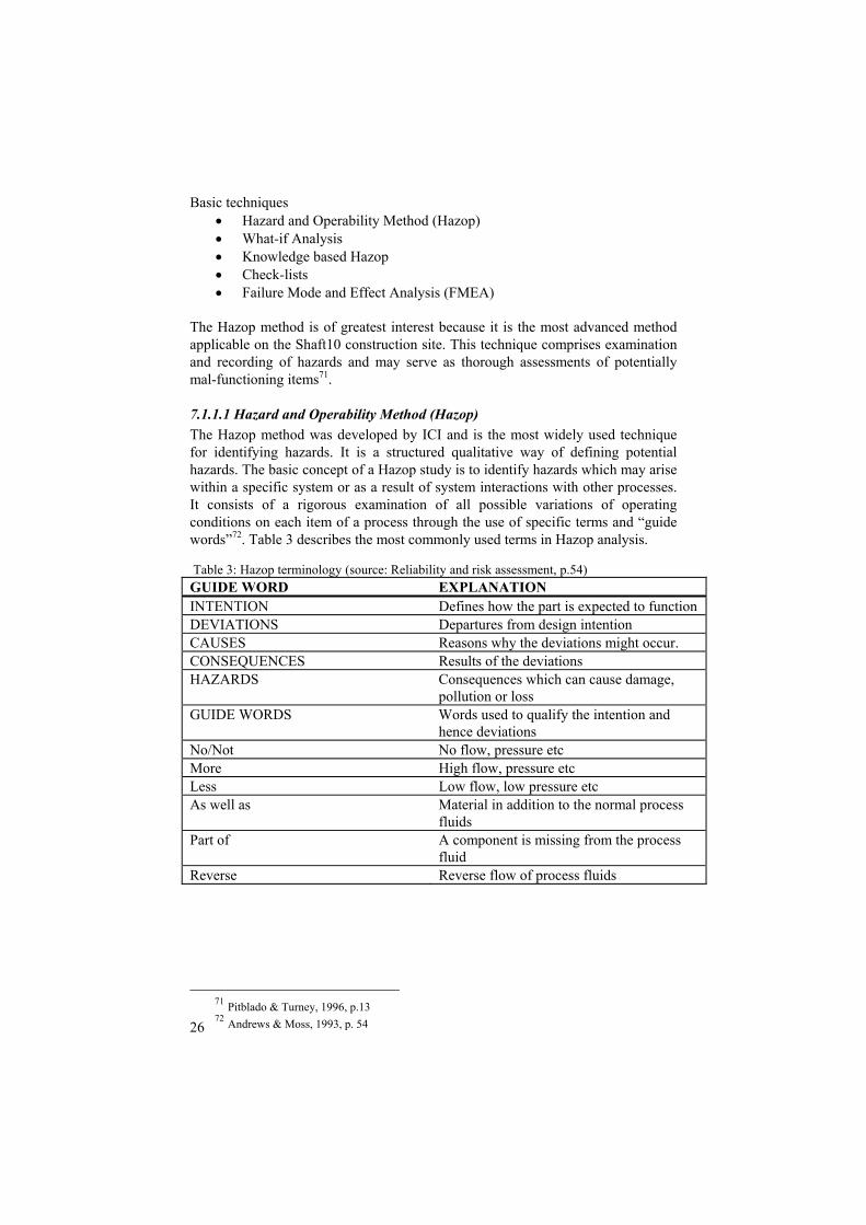
Basic techniques • Hazard and Operability Method (Hazop) • What-if Analysis • Knowledge based Hazop • Check-lists • Failure Mode and Effect Analysis (FMEA)
The Hazop method is of greatest interest because it is the most advanced method applicable on the Shaft10 construction site. This technique comprises examination and recording of hazards and may serve as thorough assessments of potentially mal-functioning items71. 7.1.1.1 Hazard and Operability Method (Hazop) The Hazop method was developed by ICI and is the most widely used technique for identifying hazards. It is a structured qualitative way of defining potential hazards. The basic concept of a Hazop study is to identify hazards which may arise within a specific system or as a result of system interactions with other processes. It consists of a rigorous examination of all possible variations of operating conditions on each item of a process through the use of specific terms and “guide words”72. Table 3 describes the most commonly used terms in Hazop analysis. Table 3: Hazop terminology (source: Reliability and risk assessment, p.54) GUIDE WORD EXPLANATION INTENTION Defines how the part is expected to function DEVIATIONS Departures from design intention CAUSES Reasons why the deviations might occur. CONSEQUENCES Results of the deviations HAZARDS Consequences which can cause damage,
pollution or loss GUIDE WORDS Words used to qualify the intention and
hence deviations No/Not No flow, pressure etc More High flow, pressure etc Less Low flow, low pressure etc As well as Material in addition to the normal process
fluids Part of A component is missing from the process
fluid Reverse Reverse flow of process fluids
71 Pitblado & Turney, 1996, p.13 72 Andrews & Moss, 1993, p. 54

27
Throughout the study, the Hazop terms are used in record sheets for each item of interest. The record sheets may describe appropriate actions to secure the process and are subsequently used as foundation for further analysis73. Both procedures 1A and 1B of the Gottlieb Skanska EMS show certain Hazop characteristics (see chapters 7.3.1 and 7.3.2), though it is standardized for application on many different types of construction projects and thus not detailed enough to take all processes into account. 7.1.2 Estimation of event probability and consequence analysis This part discusses techniques used to estimate event probabilities and the combination of these event probabilities with the result of consequence analysis to produce estimates of the overall risk from an activity. The most common definition of risk is likelihood times severity, used in the SHEMS Risk Matrix for instance. Risk or soft uncertainty is also used to define situations where 1) the set of all possible outcomes of an action is known and 2) the probability distributions of all possible outcomes is also known. Hard uncertainty is used to define situations where either 1) the set of all possible outcomes or future states is unknown or 2) where the full set of outcomes is known, but the probability distributions of all possible outcomes of the action is unknown or is not fully definable for a lack of reliable information74. The uncertainty about pollution from Shaft 10 will henceforth be defined as soft uncertainty, although the criteria are barely fulfilled. There are two basic approaches to event probability estimation. The first is direct use of statistical data on failure of systems. This is sometimes called the “historical approach”. The second is to break down the event into its contributory factors and causes, using analytical/ simulation techniques. An advantage associated with the use of historical event data is that, where the accumulated experience is relevant and statistically meaningful, the assessment will not omit any of the significant routes leading to the event. However, outdated data which may not be relevant to a specific case under study are also included, resulting in an over-estimate, usually referred to as a conservative estimate75 of the chance of the event. Careful definition of the events to be quantified is important when using analytical simulation techniques, especially in a full analysis where the probabilities and consequences of the various possible events are to be combined to produce an overall quantitative estimate76.
73 Andrews & Moss, 1993, p.56 74 Richard, 2001, p.42 75 Pitblado & Turney, 1996, p.65 76 Taylor & Spon, 1994, p.19

28
The techniques most frequently used to estimate event probabilities can be grouped as follows77:
• Fault Tree Analysis (FTA) • Event Tree Analysis (ETA) • Task Analysis
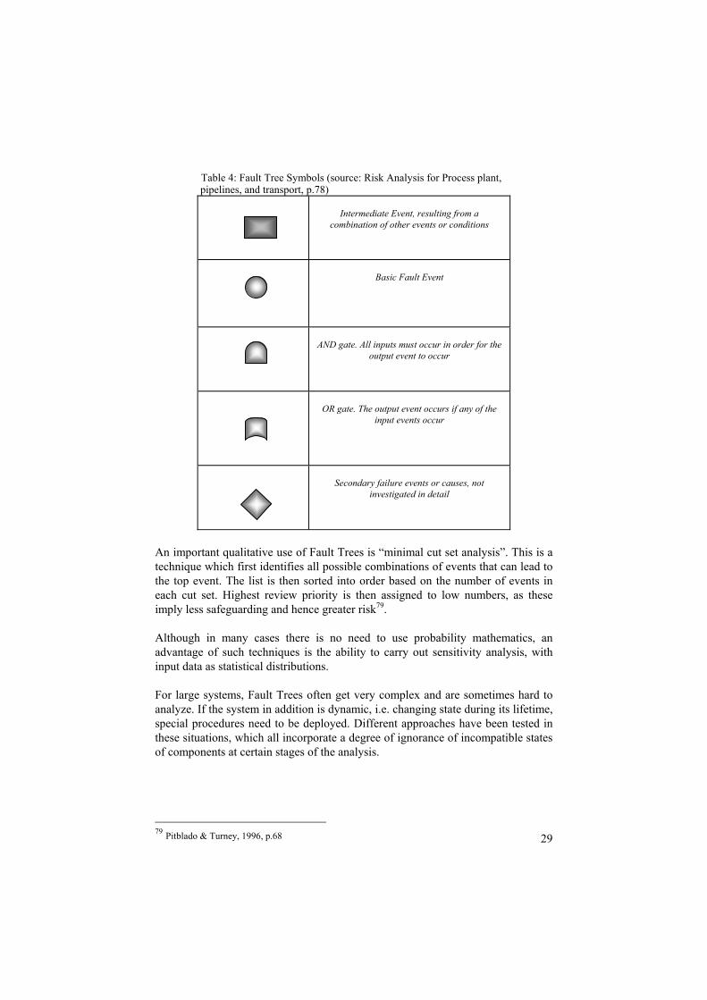
These techniques all model the mechanisms, the logical combinations or sequence of events, by which an undesired event could occur. Most of the techniques are constructed as logic diagrams and are initially qualitative in nature, although they provide models for subsequent quantification if considered appropriate. Hazop and FMEA methods (see chapter 9.1.1.1 and 9.1.1.2) do not provide the logic framework for setting down full event causes and effects which characterize logic diagram trees approaches. However, logic diagrams must start from an event which has been identified by some of those methods78. The FTA is of greatest interest in this study because it can be used as cause-consequence analyses for an enhanced assessment of risks at the Shaft 10 construction site. 7.1.2.1 Fault Tree Analysis (FTA) Fault Tree Analysis is the best known and most widely used technique for developing failure logic. The basic process is to select an undesired “top-event” and trace it back to the possible causes which can be component failures, human errors or any other pertinent events that can lead to the top event. The fault tree only includes events which contribute to its top event; it is not a model of all possible system failures. A fault tree is composed of a complex of entities known as “gates” which produce a specified output which is propagated. The most common “gates” are represented in table 4. The gates represent logical expressions with corresponding algebraic functions applied in the numerical modeling.
77 Pitblado & Turney, 1996, p.12 78 Pitblado & Turney, 1996, p.68
29
Table 4: Fault Tree Symbols (source: Risk Analysis for Process plant, pipelines, and transport, p.78)
An important qualitative use of Fault Trees is “minimal cut set analysis”. This is a technique which first identifies all possible combinations of events that can lead to the top event. The list is then sorted into order based on the number of events in each cut set. Highest review priority is then assigned to low numbers, as these imply less safeguarding and hence greater risk79. Although in many cases there is no need to use probability mathematics, an advantage of such techniques is the ability to carry out sensitivity analysis, with input data as statistical distributions. For large systems, Fault Trees often get very complex and are sometimes hard to analyze. If the system in addition is dynamic, i.e. changing state during its lifetime, special procedures need to be deployed. Different approaches have been tested in these situations, which all incorporate a degree of ignorance of incompatible states of components at certain stages of the analysis.
79 Pitblado & Turney, 1996, p.68
Intermediate Event, resulting from a
combination of other events or conditions
Basic Fault Event
AND gate. All inputs must occur in order for the
output event to occur
OR gate. The output event occurs if any of the
input events occur
Secondary failure events or causes, not
investigated in detail

30
7.2 Simulation of possible events Once the Fault Tree model has been properly constructed, a subsequent step could be to use stochastic simulation to show different scenarios involving the events embedded in those models which affect the top event of the tree (the objective function). This is done to assimilate the various uncertainties of the problem and produce a realistic appreciation of the problem’s total uncertainty80. As an extension of the Fault and Event Tree Analyses, deployment of Monte Carlo simulation fits well in the QRA-context. The use of Monte Carlo Simulation is the most viable option in many dynamic problems as it is easy to apply on real-world situations and provides results that are useful in decision-making. Monte Carlo simulation offers the most versatile of all the system analysis methods available. Independence of component failure and constant failure rates, assumptions required for most analytic methods, are not required for simulation. Systems can thus be modeled in whatever level of detail required81. The basic approach to Monte Carlo simulation is to transform the single point values (“best guess estimates”) describing uncertain events in a deterministic model into distributions. The uncertainties in these estimates mean that they can be treated as random variables, which in turn can be described by a probability distribution with a probability density function (PDF). A probability distribution is a plot of the probability density (i.e. relative frequency) versus the data variables to describe the behaviour of a random variable82. The PDF can also be represented by its Cumulative Distribution Function, (CDF). The CDF is obtained by adding (accumulating) the individual increments of the probability distribution function. As will be shown, the cumulative density function is defined as the probability that any outcome in X is less than or equal to a stated limiting value x. The PDF is the slope of the CDF. The CDF is very useful when depicting and comparing risks. For clarification, the Monte Carlo approximation works in the following way83: Suppose a known model is given: Y=F(X) Y=Output X=Input along with a probability distribution function F, where ( ) ( )axaF ≤= Pr for the value of the input x.
80 Vose, 1996, p.1 81 Andrews & Moss, 1993, p.260 82 McBean & Frank, 1998, p.18 83 Cox, 2002, p.80
31
The probability distribution of y can be approximated by (a) Randomly drawing multiple values of x from F, (b) Calculating ( )ii xfy = for each sampled input value ix ; and (c) Forming the sample distribution function of the resulting
iy values. This sample distribution approximates the true probability distribution of y induced by the probability distribution of x. During simulation performed by software packages, this sampling method is run over and over again, each time with a random number between 0 and 1 to generate a random sample for the probability distribution84. Through the use of Monte Carlo simulation, the distribution of the top event probability in terms of the individual parameters distributions may thus be determined85, which provides a good explanatory ground for sensitivity analysis and comparison of risks. 7.4 Tolerability and acceptability of risk The above analysis, if mannered correctly and applied in an accurate way, provides a comprehensive quantitative risk assessment. The degree of “completeness” of the analysis always varies from project to project depending on the complexity of the project, availability of significant data, costs and the types of uncertainty and consequences faced by the decision-maker. When the uncertain situation is fully replicated, given the constraints mentioned above, the following step is to make the decision regarding acceptance of the risk/risks. Although the QRA is an important factor in decision-making, the acceptance of an activity should not be based on risk alone86. Sound decisions are unlikely to be reached if no consideration is given to the uncertainty in the risk estimates, the costs of reducing the risks, other costs to the organization or society of the activity or the benefits to be derived from it. The choice of accepting or not accepting the risk/risks may be facilitated by the definition and deployment of certain criteria. Three classes of concepts can be defined and are depicted in chart 387:
• an “intolerable” level of risk at or above which immediate action to reduce the risk or terminate the activity is called for, irrespective of cost
• a “broadly acceptable” level at or below which further reduction measures are nor required
• a middle region where additional risk reduction measures are necessary until their overall cost becomes grossly disproportionate to the risk
84 Vose, 1996, p.40 85 Andrews & Moss, 1993, p.260 86 Pitblado & Turney, 1996, p.91 87 Pitblado & Turney, 1996, p. 91

32
reduction produced. This is classed as “as low as reasonable practicable” (ALARP)
The higher and more unacceptable a risk is, the more proportionately one is to spend to reduce it. This implies a considerable effort even to achieve a marginal reduction. There may come a point where even a marginal further reduction would be unjustifiably expensive and the obligation to improve is discharged88. Where the risks are less significant, the less proportionately it is worth spending to reduce the risk. At the lower limit where the risks are ”broadly acceptable” the levels of risk are so insignificant that further reduction is not necessary, provided that the risk levels will be attained in practice89. ALARP implies that, in making a judgment, the total cost and inconvenience associated with risk reduction measure may be weighed against the benefits of reduced risk.
Once a risk is found to be in the ALARP region, cost-benefit analysis may be used as an aid to decision making. In the simplest case, the total cost of the measures 88 Pitblado & Turney, 1996, p.92 89 Pitblado & Turney, 1996, p.93
The ALARP region (risk is undertaken only if a benefit is
desired)
Intolerable region
Risk cannot be justified on any grounds
Broadly acceptable region
Intolerable level
Tolerable only if risk reduction is
impracticable or if cost is grossly
disproportionate to the improvement
gained
Tolerable if cost of reduction would exceed the
improvement gained
Chart 4: Level of risk and ALARP (source: Risk Assessment in Process Industries, p.92)
Negligible risk

33
necessary to reduce the risk may be set against the achieved risk reduction and decisions made on the best option to adopt. 7.5 Cost-Benefit Analysis (CBA) A CBA summarizes the positive and negative aspects of an alternative into one number. A CBA will shed much light on four central features of an environmental project: (1) the efficient level of protection that balances the benefits and costs of additional protection; (2) the optimal mix of environmental features in the alternative; (3) the optimal size or scale of the project; (4) the optimal timing of when to implement the components of the management action90. An important element is establishing what the baseline, or effects without the policy, would be. The effects of the policy are then compared to a future state of the world without the policy to establish the net effect of the policy, which avoids using a “before vs. after” viewpoint, which may attribute some changes that occur at the same time as the policy implementation to the project, when in fact the changes were already underway91. Defining the benefits and determining in which way these benefits are to be valued are other crucial but difficult tasks. Monetizing environmental safety and progress is often considered controversial, as we are unfamiliar thinking of these issues in market terms. However, not including them in a CBA will lead to a distorted answer in the analysis92. In addition to carefully define and monetize the benefits and costs, discounting these items over time is necessary for an analysis. This is due to the simple fact that a dollar today is worth more than a dollar tomorrow, as people prefer their benefits now rather than later. People might also invest their money in some productive enterprise to yield a net return93. A common means used to discount future streams of benefits and cost is the Net Present Value (NPV). As the name implies, NPV is the present value of the benefits minus the present value of the costs. The difference is the net gain adjusted for the timing of benefits and costs. The units of measurement are present worth of dollars in the base year in which all of the benefits and costs are figured. The definition of NPV can be illustrated by the equation94
( )∑= +
−=
T
ttr
CtBtNPV0 1
where:
90 Loomis & Helfand, 2001, p.105 91 Loomis & Helfand , p.107 92 Loomis & Helfand, p.109 93 Loomis & Helfand, p.141 94 Loomis & Helfand, p.151

34
Bt = Benefits in time period t Ct = Costs in time period t r = interest rate t = time period If NPV is used as a decision rule, then only projects with NPV greater than zero are accepted as economically efficient. NPV might be seen as a discounted measure of whether the environmental management action represents a potential Pareto improvement over the life of the project, which indicates a situation where nobody loses from a policy, and at least some gain.
8. Application of the theory
The previous chapters 6, 7, and 8 review the construction operations, the implementation of the EMS and regulations directing the work, while Chapter 9 describes QRA-theory. This part seeks to relate the contents of the preceding chapters to each other, providing an application of the theory on the on-going operations of Shaft 10. The objective is to demonstrate a more quantitative Risk Analysis as an alternative to Gottlieb Skanska’s Risk Assessment and to prove its robustness using data collected through surveys and by reviewing SHEMS templates and environmental monitoring data from previous similar Gottlieb Skanska projects. The numerical data are used in models in Microsoft Excel and its add-in @Risk. The analysis follows as close as possible the steps described in chapter 9, although some deviations occur, caused by limited amount of data and other inconsistencies between theory and practical implementation. The major elements of environmental assessment include a review of existing information, initial site visit, and a review of potential assessment methods, assessment design, data analysis, risk assessment and remediation95. The general approach is to carry out a QRA-analysis for possible contamination of the water in the West Branch Reservoir. Firstly, the analysis takes no account of Gottlieb Skanska’s measures and controls to protect the water. Secondly, those results get compared with the results from an exact same analysis but now considering the controls implemented at the site. The first results function as the “base-line case” without controls, which in comparison with the second “implemented policy case” with controls provides a foundation for Cost-Benefit Analysis. The two analyses differ from each other only in the simulation stage, where the reduction of likelihood of the various events gets accounted for. A Hazop Analysis identifies potential sources of contaminants in the reservoir from Shaft 10 and their consequences, which is used as support for the Fault Tree Analysis. The Fault Tree Analysis is constructed based on the Hazop and information about cause-consequence relationships in between activities at the construction site and environmental impact. 95 Louvar & Louvar, 1998, p.285

35
To simulate various scenarios of possible events that could cause discharges to the West Branch reservoir, a model is constructed in the Microsoft Excel add-in @Risk. Probability distributions are assigned to the uncertain components of the model, which were defined in the Hazop and Fault Tree Analyses96. The probability distributions describe the amount of discharges from the activities/events while the severity of the discharge is captured through an impact factor ranging from 1-10 for the activities/events, which is multiplied with the probability distributions97. The following text reviews special features of the model, its constraints and assumptions about the variables. Data about leakage of Asbestos materials where gathered from old environmental audits. Information about probability of leakage from machines, workers handling substances, soil erosion and solid materials come from surveys directed to the workers and the safety engineer at the construction site. The model thus involves elements of subjective estimation due to lack of relevant historical data. Error and bias problems are addressed through the forming of the surveys and the choice of probability distributions used to model the potential environmental problems. In general, non-parametric/general distributions are better for modeling subjective expert opinion than parametric/theoretically derived distributions. The distinction between the two groups of distributions may be expressed as follows. The shape of theoretically derived distributions is borne of the mathematics describing a theoretical problem while general distributions’ mathematics are defined by the shape that is required. The two distributions used in this model are the Trigen distribution for the variables with data from surveys and the General distribution for Asbestos variable, with data from old environmental audits. Both these distributions are general and intuitively easy to understand98. The Trigen distribution is an extension of the Triang distribution and requires 5 parameters: a) the practical minimum, b) the most likely value, c) the practical maximum value, d) the probability that the value could be below a, e) the probability that the value could be below c. d) and e) are set to 0 and 90 respectively. This distribution is useful when it is fairly easy to estimate the minimum and most likely values of a variable, but the maximum is almost unbounded and could be enormous99. The distributions also need to be constrained to fit the reality of Shaft 10. There can for instance not be a positive environmental impact from Shaft 10, a fact which is expressed through truncation of all the variable’s probability distributions so their minimum value is 0. All variables have continuous distributions and may take several values within a range determined by the information from the surveys. The range represents the amount of discharges for the whole period of 96 Vose, 1996, p.190 97 Pers. Med., Official NYCDEP 98 Vose, 1996, p.56 99 Vose, 1996, p.168

36
reconstruction, which is 75 months. Correlations between the different variables might be observed for three reasons. The first is that there is a logical relationship between the variables. The second is that there is another external factor affecting both variables. The third reason is that the observed correlation has occurred purely by chance and no correlation actually exists100. For this analysis, a correlation matrix is used to correlate the probability distributions of leakage and erosion together because the activity of the machines at the site affects both probabilities. To account for the reduction of risk of discharges to the watershed, estimates gathered through surveys are used. The controls are estimated to decrease the discharges with 50% for leakage from machines, 40% for manual spill, 75% for solid materials and soil erosion and 90% for spillage of hazardous waste. The probability that the value could be below the practical maximum of the distribution is raised to 95101. The most important outputs of the two simulations are 1) general statistics for each variable that may be used for comparison of the “base-case” and “implemented policy case”, 2) Tornado graphs depicting the dependency of the overall environmental impact on the risky activities for the two cases, and 3) Cumulative Distribution Functions (CDFs) for each variable. The CDF graphs are very useful when comparing risks, as they picture the uncertainty of a given situation, are comparable and intuitively easy to understand. The CDF is S-shaped for a typical bell-shaped Probability Distribution Function (PDF)102. In this analysis, the graphic depiction of the CDFs for the activities has cumulative probability on the vertical axis and amount of discharges on the horizontal axis, while the CDF for overall environmental impact incorporates severity of the various discharges on the horizontal axis as well. Probabilities for particular intervals can be extracted from the curve by reading off fractile values. A fractile is that value of the uncertain variable for which the probability that the variable is smaller than the fractile is the fractile103. In other words, a cumulative probability on the vertical axis matching a point on the curve is the probability that the variable takes on values below the point on the curve. The variance of the uncertain variable is represented by the slope of the curve. A steeper slope represents less variance of the variable. Also, the farther to the right the curve is, the greater amount of discharges is covered by the cumulative probability.
9. Results
100 Vose, 1996, p.192 101 Survey seven construction workers and safety engineer, 2005 102 Hardacker et al., 2002, p.39 103 Hardacker et al., 2002, p.41

37
This chapter reviews the results from the environmental QRA. Brief comments about the results are included, whereas a more thorough analysis is presented in next chapter. 9.1 The “base-line case” Subsequent to the Hazop and Fault Tree Analyses (see appendices I and J) the simulation of the “base-line case”, without considering controls, yielded statistics shown in table 5. The unit in table 5 and table 6 is an artificial measurement based on the probability of each type of discharge times the consequence of that discharge. The overall impact to the reservoir is a summation of each discharge’s figure, which comprise all probability distributions times their consequence into one number, specific for this job site and comparable only with results from the same model. Table 5: Statistics from simulation, no controls considered (source: @Risk model)

38
To depict how much each of the variables affects the overall impact to the reservoir, the top event, a Tornado graph is constructed (chart 4). The Tornado graph is a visual representation of a regression with the overall impact as dependent variable and the various events as independent variables. Each activity’s bar and attached number describes its contribution to the overall impact to the reservoir.
Variables Minimum Maximum Mean St dev Variance Dependent variable
Overall impact to the reservoir
315.84 67.13 534.54 78.50 6162.19
Independent variables
Excavator breakage
0.25
27.55
11.13
5.91
34.93
Truck breakage
0.20 34.38
14.02
7.31
53.48
Car breakage 0.02 6.98 2.70 1.57 2.48 Drill breakage 0.16
20.45
8.66
4.36
19.04 Crane breakage
0.05
27.84
10.32
6.38
40.75
Spill workers 0.51 39.88 18.37 8.28 68.58 Wood 1.16 133.07 61.79 27.56 759,80 Metal 0.19 53.83 23.06 11.45 131.09 Bricks 0.19 40.82 17.14 8.89 79.07 Miscellan 0.28 26.81 11.72 5.73 32.90 PCB 0.03 14.31 5.12 3.28 10.79 Mercury 0.05 14.26 5.20 3.31 10.99 Lead 0.09 27.62 11.03 6.07 36.88 Asbestos 1.00 8.06 3.36 1.68 2.82 Erosion Cars 0.56 105.65 49.37 21.82 476.52 Erosion Exc 2.32 270.31 117.15 57.25 3278.40 Erosion Tru 0.97 202.50 87.98 43.28 1873.70 Erosion Cra 1.01 94.34 41.63 19.73 389.40

39
Chart 5: Tornado graph without controls (source: @Risk Model) 9.2 The “Implemented policy case” The simulation of the “implemented policy case”, considering controls, yielded statistics shown in table 6.
Bricks/C17 ,055 Cars/C7 ,056 Metal/C16 ,074 Lead/C23 ,076 EroCrane/C30 ,122 EroCars/C27 ,134 Drill/C5 ,169 Wood/C15 ,172 Excavator/C6 ,23 Crane/C9 ,241 Trucks/C8 ,276 EroTrucks/C29 ,278 Workers/C12 ,312 EroExca/C28 ,378 Mercury/C22 ,402 PCB/C21 ,411
@RISK Student VersionFor Academic Use Only
-1 -0,75 -0,5 -0,25 0 0,25 0,5 0,75 1

40
Table 6: Statistics from simulation, controls considered (source: @Risk Model) Variables Minimum Maximum Mean St dev Variance Dependent variable
Overall risk 87.80 265.85 175.34 26.70 713.02 Independent variables
Excavator breakage
0.16 11.92 5.11 2.59 6.71
Truck breakage
0.04 15.03 6.41 3.27 10.68
Car breakage 0.05 2.97 1.23 0.68 0.46 Drill breakage 0.18 8.99 3.97 1.89 3.58 Crane breakage
0.18 12.24 4.80 2.88 8.27
Spill workers 0.99 20.72 10.73 4.55 20.71 Wood 0.64 29.59 14.44 6.39 40.79 Metal 0.15 11.68 5.35 2.54 6.45 Bricks 0.33 9.05 3.72 1.88 3.55 Miscellan 0.12 5.87 2.76 1.20 1.43 PCB 0.02 1.21 0.46 0.29 0.08 Mercury 0.01 1.19 0.45 0.28 0.08 Lead 0.02 2.44 1.01 0.55 0.30 Asbestos 1.01 7.64 3.43 1.62 2.61 Erosion Cars 0.45 23.38 11.35 4.83 23.33 Erosion Exc 0.49 60.01 26.65 12.79 163.62 Erosion Tru 1.77 44.75 19.30 9.29 86.25 Erosion Cra 0.37 20.61 10.14 4.44 19.72 A Tornado graph is constructed considering controls, which in comparison with chart 4 clearly shows how the weights of the independent variables change with and without controls.
Bricks/C17 ,038 Metal/C16 ,051 Cars/C7 ,082 EroCrane/C30 ,089 EroCars/C27 ,097 Mercury/C22 ,114 PCB/C21 ,116 Wood/C15 ,129 EroTrucks/C29 ,187 Drill/C5 ,229 EroExca/C28 ,258 Excavator/C6 ,313 Crane/C9 ,348 Asbestos/C24 ,391 Trucks/C8 ,395 Workers/C12 ,55
@RISK Student VersionFor Academic Use Only
-1 -0,75 -0,5 -0,25 0 0,25 0,5 0,75 1

41
Chart 6: Tornado graph with controls (source: @Risk Model) 9.3 In-depth assessment of the environmental risk To properly compare the environmental risks of the defined events and the overall environmental risk, CDF graphs are used. The CDF graph for the dependent overall environmental impact is shown here while the CDF graphs for the independent activities are shown in appendix K (see appendix K). The resulting CDF from both simulations are shown in the same graph in chart 6 to facilitate comparison.
Cdfs Overall Impact
0
1 0 0
2 0 0
3 0 0
4 0 0
5 0 0
6 0 0
7 0 0
8 0 0
0 50 100
150
200
250
300
350
400
450
500
550
600
650
700
750
800
Environmental impact
Cum
ulat
ive
prob
abili
ty
up to
1
0
5 0
1 0 0
1 5 0
2 0 0
2 5 0
Without controls With controls
Chart 7: CDF-curves for overall environmental impact (source: @Risk Model) 9.4 Cost-Benefit Analysis The intention of this section is to compare the benefits of the EMS to the costs of implementing the EMS for Skanska. Although there conceptually are few obstacles in applying the theory of Chapter 9.5, lack of information about both costs and benefits makes any form of relevant analysis difficult to make. An obvious problem is that there exists no concrete value in monetary terms of the benefits. Such benefits include: enhanced company image; which attracts investors, customers and business partners and lower probability of fines and lawsuits. The EMS also works as a quality mark which facilitates interactions with interest groups such as communities affected by Gottlieb Skanska projects and landowners.

42
10. Analysis
In this chapter analyses of the results are presented. A comparative analysis of the states with and without controls is presented. Comparing the effects of the different regimes is more justified if the results all come from the same model, which it does in this analysis. All models have some error in them and comparisons are better if the form of error is constant across the results104.
10.1 Comparison of the results with and without controls The diagrams in Appendix 11 clearly depict that the controls have a tremendous impact on the risk of pollution from activities at Shaft 10 to the West Branch reservoir. The CDFs considering controls all show a smaller range of kilogram discharges and a smaller variance. Hence, the probability of discharges decreases for all activities. Using a 50/50 approach, a certain amount of each type of pollution for which there is a 50% probability of lower discharges are shown in table 7 with and without the controls. The 50/50 concept is good to use since it is easier to understand a 50% chance than a 40% or 60% chance for example. The figures in table 7 can also be extracted from the CDF-graphs by drawing a line from the middle of the cumulative probability axis and see where it crosses the S-shaped CDF-curve. Table 7: Comparison of cumulative probabilities (source: @Risk model)
104 Loomis & Helfand, p.69

43
The shapes of the CDFs are similar within the groups Spillage machines and workers, solid materials, hazardous waste and soil erosion. These similarities are due to similar characteristics within the group regarding the amounts of releases. Regarding the relative effect of the releases on the total environmental impact, chart 4 and 5 illustrate the change before and after the controls. This change foremost reflects the effectiveness of the controls. The most significant changes are the decrease of importance of discharges of PCB and Mercury due to rigorous waste control, the disappeared effect from lead paint for the same reason, and the ending or decreasing impact of soil erosion from the excavator and trucks, much thanks to the Gabion wall control. The greatest threats to the water of West Branch Reservoir after the controls are implemented seem to be spillage, mostly from workers and trucks. Manual spill will be the sole greatest contributor to discharges, which makes sense, since humans are far more flexible than vehicles and other machines and more easy slip through controls preventive systems. The overall risk of environmental impact changes dramatically after the controls are implemented. The horizontal axis of chart 6 is not amount in kilograms, but a measurement of all the individual releases multiplied with their severity factor and added up. It is an artificial constructed unit which facilitates the comparison of the total effect of the controls. The “with controls”- function does not reach 0 which implies that some impact is inevitable, but it does not clarify what type of impact. As long as the activities of the construction site do not raise the levels of regulated
Discharges 50% without controls 50% with controls Kg Spill from Excavator 12 5 Kg spill from Trucks 14 6 Kg spill from Cars 2,7 1,5 Kg spill from Drill 6,8 2,7 Kg spill from Crane 7,9 3,5 Kg spill from workers 16 10 Kg Wood 60 12 Kg Metal 22 5 Kg bricks 14 3 Kg Miscellaneous 11 3 Kg PCB 4,5 0,2 Kg Mercury 4,5 0,2 Kg Leaded paint 10 0,7 Kg Asbestos material 3 0,025 Kg Soil Erosion Cars 50 10 Kg Soil Erosion Excavat 120 25 Kg Soil Erosion Trucks 90 18 Kg Soil Erosion Crane 38 10

44
substances in the water, which is controlled for by the balloon instruments, some discharges are allowed. The range of the CDF is shifted backwards and the slope decreases after the controls are implemented, showing a more environmental sound situation with the controls. 10.2 Comparison of the SHEMS risk assessment and the QRA The QRA represents a more in-depth and detailed assessment of the environmental risk. It also involves hard numbers in contrast to the SHEMS assessment. The two analyses still have similarities and reach equal results, where the QRA supports the qualitative approach. The similarity of the results might be related to two things; the estimates of discharges come from the same people that stand behind the SHEMS, or the actual qualitative analysis is well performed. The form of the surveys and the distributions for the simulation allows for estimation of the independent variables, which helps replicating the situation at the Shaft 10 throughout the 75 month project. Examples of similarities in between SHEMS and QRA is the great effect from worker spill on the water after controls are implemented shown in the Tornado graph (see chart 6) and a stated emphasis on EMS training and education throughout the project. The management acknowledges that the worker spill is a great source of pollution after the preventive controls. For environmental management projects, decision makers may currently receive four types of technical input: modelling/monitoring, risk analysis, cost or cost-benefit analysis and stakeholder preferences. While modelling and monitoring results are usually presented as quantitative estimates, risk assessment and cost-benefit analysis incorporate a higher degree of qualitative judgment by team members and experts105. In contrast to the SHEMS assessment, the QRA is restricted to analysis of impact on the watershed. Protection of the water is the most important issue in the SHEMS to, because of the nature of the project, but the analysis is not limited to those risks. 10.3 Tolerability of risk and CBA Although a full analysis can not be formulated, some general points relating the theory to this real-life situation need to be made. Before the controls, most of the defined activities/threats are in the intolerable region. In this region, a Cost-Benefit Analysis is not necessary, as the risks need to be reduced at any cost. Bricks, metal and leakage from cars are in the upper ALARP region, and for these activities/threats a Cost-Benefit Analysis would be justified if the controls where
105 Linkov & Bamadan, 2004, p.57

45
aimed only at these variables. Now this is not the case, the controls are installed to prevent general discharges or leakage. For example, the silt fence reduces the risk of any solid material reaching the watershed, not only metal. When the controls have been implemented, further preventive measures’ costs are disproportional to the benefits of reducing the risks even more, and all defined activities/threats are in the ALARP region. The residual risk is bearable and accepted. A CBA would require knowledge of benefits of the risk reduction, which is difficult to quantify.
11. Conclusions
The main objective of this study is to present an alternative way of assessing environmental risks in the construction industry. The activity at the Shaft 10 construction site is used as example, on which the methodology is applied. Since QRA provides an assessment of environmental safety, and safety in turn is highly dependent on environmental management, the link between QRA and environmental management is important. In comparison with the present risk assessment, the QRA results do not deviate much from the present outcomes, although the QRA in more detail addresses environmental threats. The advantages of a quantitative analysis might be more evident if it was applied on more complex projects than the Shaft 10 remediation and if data about releases and their consequences where attainable. The context in which this project was undertaken didn’t allow much use of historical data from previous similar construction projects, which forced the risk analysis to be based mostly on assumptions. The use of assumptions from the same persons who carried out the original Risk Assessment results, not surprisingly, in similar outcomes. Nevertheless, the strength of this probabilistic approach is in using available data to determine whether conclusions can be drawn. Generic data is combined with sound expert judgment to attain the most realistic model possible. The assumptions in the models can to a large degree be justified from the employee’s experiences, which make the model credible. Those assumptions identify the key variables that influence the system under study and help identify how these variables are related to each other. The main purpose of this study is to depict a method which may be used alternatively or complementary to the current Risk Analysis procedures for any construction project that needs in-depth examination of its uncertain impact on the environment. A distinctive characteristic of construction projects is their relatively short life-cycle, compared with plants and other facilities with repeating processes and practices. A construction project is much more dynamic and changeable. This actuality presents a tremendous challenge for planners and decision-makers as the

46
implementations of routines and systems have to be done more often and on transforming objects. An obvious advantage of the QRA is that it gives the Environmental Manager hard numbers to rely on when arguing for preventive measures and actions. It also reduces the degree of random mistakes in the EMS procedures and, if managed correctly, replicates the reality in a detailed and consistent way which together with knowledge and sound judgment optimizes environmental management. A QRA study gives managers an instrument to better conclude how to best allocate resources. An activity that mistakenly is heavily controlled for might actually need less attention with less cost and vice versa. These kinds of situations can be depicted and clarified through QRA. A limiting factor for the use of QRA is the large amount of information needed to perform an analysis. Either based on historical data or subjective assumptions, the risk assessment requires a substantial basis to present relevant results. Another challenge for contractors would be to perform unique analyses for each and every construction project, since they have different conditions and types of impact on the environment. The DEL-159 project meets or exceeds all environmental regulations so far, which is aligned with Skanska’s environmental policy. The current environmental procedures at the Shaft 10 construction site is profound and efficient As it seems, one of the most important objectives of Gottlieb Skanska’s EMS is to avoid environmental disasters and bad publicity. The company’s relatively high exposure to operative risks related to the environment and safety issues would suggest a proactive approach in handling these kinds of risks, where QRA could come to play an important part. The worldwide implementation of EMS at all Skanska units in the late nineties was not cheap, and it shows the emerging importance of environmental issues as factors in corporate strategic planning. 12. References

47
Text
Andrews J.D. and Moss T.R., (1993), Reliability and Risk Assessment, Longman Scientific and Technical, Essex Cox L. A., (2002), Risk Analysis. Foundations, models and methods, Kluwer Academic Publishers, Norwell, Massachusetts Edwards A. J., (2004), ISO 14001 Environmental certification step by step Elsevier Butterworth- Heinemann, Oxford Gottlieb Skanska, (2001), Safety, Health and Environmental Policy Statement Skanska Six Month report, January-June, (2005) Gottlieb Skanska, (2005) Safety, Health and Environmental Management System (2002), Hamilton G., (1996), Risk Management 2000, Studentlitteratur, Lund Hardacker J.B., Huirne R. B. M and Anderson J.R, (2002), Coping with Risk in Agriculture, Cab International, Wallingford Hyödynmaa M, (2002), Miljöledning i byggföretag- motiv, möjligheter och hinder (Licentiatavhandling Institutionen för industriell ekonomi och organisation) KTH, Stockholm. Loomis J. and Helfand G., (2001), Environmental Policy Analysis for decision making, Kluwer Academic Publishers, Norwell, Massachusetts Louvar J. and Louvar D., (1998), Health and Environmental risk analysis: Foundations with applications, Prentice-Hall PTR Environmental Management and Engineering series vol. 2, Prentice-Hall, New Jersey Linkov I. and Bamadan A, (2004), Comparative Risk Assessment and EnvironmentalDecision Making, Earth and Environmental Sciences- VOl. 38, Kluwer Academic Publishers, Dordrecht, Netherlands McBean E and Frank R., (1998), Statistical Procedures for analysis of environmental monitoring data and risk assessment, Prentice-Hall PTR Environmental Management and Engineering series vol.3, Prentice-Hall, New Jersey New York City Department of Environmental Protection, (2005), Rules and regulations for the protection from contamination, degradation and pollution of the New York City water supply and its sources

48
Pitblado R. and Turney R., (1996), Risk assessment in the process industries, Second Edition. Institution of chemical engineers, Rugby, Warwickshire Richard Y., (2001), Uncertainty and the environment- Implications for decision making and environmental policy, Edward Elgar Publishing Ltd, New York SIS FORUM AB, (1998), Miljöledningsguiden: steg för steg mot ISO 14001 och EMAS Görmangruppen AB, Stockholm Skanska, (2004), Skanska Annual Report 2004 Skanska, (2005), Skanska Six Months Report January-June 2005 Skanska, (2005), Skanska Sustainability Report 2004 Taylor J.R. and Spon E., (1994), Risk Analysis for Process plant, Pipelines and transport, Chapman and Hall, London Vose D, (1996), Quantitative Risk Analysis: A guide to Monte Carlo simulation modelling John Wiley & Sons Ltd, Sussex Web-based Skanska, www.skanska.com , 2005-09-05 Skanska USA, http://www.skanskausa.com/templates/Page.asp?id=3253, 2005-09-15 Skanska USA Civil, http://www.usacivil.skanska.com/ ,2005-09-15 Gottlieb Skanska, http://www.gottlieb.skanska.com/index2.html 2005-09-15 NYC Department of Environmental Protection http://www.ci.nyc.ny.us/html/dep/html/croton.html 2005-10-03 Great Achievements, http://www.greatachievements.org/?id=3610, 2005-10-01 The environmental Protection Agency 1. http://www.epa.gov/opptintr/pcb/, 2005-10-20 2. http://www.epa.gov/mercury/ , 2005-10-20 3. http://www.epa.gov/air/urbanair/lead/what.html 2005-10-20 4. http://www.epa.gov/asbestos/help.html#Docs, 2005-10-20 5. http://www.epa.gov/region5/water/cwa.htm, 2005-10-20

49
ISO-14001 Certification http://www.iso14000-iso14001-environmental-management.com/iso14001.htm, 2005-10-18 Dagens miljö http://dagensmiljo.idg.se/ArticlePages/200305/05/20030505142546_DMI258/2003050514 2546_DMI258.dbp.asp , 2005-11-13 The Department of Environmental Concervation 1. http://www.dec.state.ny.us/website/regs/subpart360_14.html , 2005-11-10 2. http://www.dec.state.ny.us/website/regs/part364.html , 2005-11-10 3. http://www.dec.state.ny.us/website/regs/part370.html , 2005-11-10 4. http://www.dec.state.ny.us/website/regs/part371a.html , 2005-11-10 5.http://www.dec.state.ny.us/website/dshm/regs/370parts.htm , 2005-11-10 Interviews tour and surveys Pappalardo Stefano, Safety Engineer, contract DEL-159, NY, 2005-09-09 Quinn Michael, Environmental Director, Gottlieb Skanska, NY, 2005-10-02 Guided tour around the construction site, 2005-09-09 Survey 7 workers and Safety Engineer E-mail interview, official NYCDEP

Appendix A
Skanska Organizational Chart
Source: www.skanska.com

Appendix B
Skanska USA Civil Operating Units Operating unit Location Specialization Slattery Skanska
Queens, New York
Rail transportation projects, tunnels and water pollution control plants
Gottlieb Skanska Queens, New York
Power generating facilities, road and rail tunnels
Koch Skanska
New Jersey
Bridges and other support structures for transportation agencies
Tidewater Skanska
Virginia
Bridges and other support structures for transportation agencies
Fairfield Skanska
Virginia
Bridges and other support structures for transportation agencies
Atlantic Skanska
Atlanta, Georgia Wastewater treatment plants and rail maintenance facilities
Yeager Skanska
California Highways, dams, bridges, airport and flood control structures.
Tidewater Skanska
Cortez, Colorado Water filtration plants, bridges, roads, drydocks, tunnels, cement plants and natural gas treatment plants.
Nielson Skanska
Cortez, Colorado Water filtration plants, bridges, roads, drydocks, tunnels, cement plants and natural gas treatment plants.
Bayshore concrete products
Cape Charles, Virginia Manufactures all types of prestressed concrete fabrications and Underpinning & Foundation
Maspeth Maspeth, New York Underpinning and pile driving
Source: http://www.usacivil.skanska.com

Appendix C
Map of East of Hudson Watersheds
Source: http://www.ci.nyc.ny.us/html/dep/html/wsmaps.html

Appendix D
Plan of the Shaft 10
Source: Gottlieb Skanska
Operators - Contains PCB - Contains Mercury
Ceiling, windows - Asbestos
Storage Area Hazardous and Non-hazardous Waste
Stairs, bricks - Lead
Gate Wells - PCB from Operators - Mercury from Operators

Appendix E
SHEMS Summary of Significant Environmental Aspects
Source: Gottlieb Skanska SHEMS p. 20

Appendix F
SHEMS Risk Matrix
Source: Gottlieb Skanska SHEMS p. 25

Appendix G
Map of construction site
Source: Mapquest, own
Shaft #10
Floating Balloons
Instrument
Offices
Gate to Job-site
Containers
Gabion Wall
Silk fence
Turbidity Curtain
Catch Basin
Hey over drain
Waste Storage Hazardous and Non-hazardous
Significant Environmental Hazards at the reconstruction site of Shaft #10:
• Soil Erosion • Leakage • Hazardous waste

Appendix H
System Specific Characteristics: Reservoir Standards (mg/L)
Source: Rules and Regulations for the protection from contamination, degradation and pollution of the New York City water supply and its sources, page 111.
Annual mean Single Sample Maximum Alkalinity (mg CaCO3)
≥ 40.00 ≥ 10.00
Ammonia Nitrogen
0.05 0.10
Chloride 30.00 40.00 8.00 Nitrate+ Nitrate- N
0.30
0.50
Organic Nitrogen
0.50
0.70
Sodium
15.00 20.00
Sulfate
15.00 25.00
Total Diss. Solids
150.00 175.00
Total Organic Carbon
6.00 7.00
Total Susp. Solids
5.00 8.00
Chlorophyll-a 0.01 0.015

Appendix I
Hazop Chart
Description Activity/ Event
Guide Word
Deviation Possible Cause
Consequences Severity *
Discharge Equipment breakage
** ***
Excavator less of more of part of
seal pressure missing
wear out over-use no maintenance
Leakage of oils and/or gasoline to the ground
3
Trucks less of more of part of
seal pressure missing
wear out over-use no maintenance
Leakage of oils and/or gasoline to the ground
3
Cars less of more of part of
seal pressure missing
wear out over-use no maintenance
Leakage of oils and/or gasoline to the ground
3
Drills less of more of part of
seal pressure missing
wear out over-use no maintenance
Leakage of oils and/or gasoline to the ground
3
Crane less of more of part of
seal pressure missing
wear out over-use no maintenance
Leakage of oils and/or gasoline to the ground
3
Spillage from workers handling hazardous substances
** ***
Manual work
Less of More of
Caution
Not trainedenough overworked
Leakage of hazardous substances to the ground
3
Solid materials
Wooden More of
Overfull container
Not emptied regularly
Wooden trash in reservoir
0,5
Metal More of Overfull container
Not emptied regularly
Pieces of metal in reservoir
0,5
bricks More of Overfull container
Not emptied regularly
Bricks or pieces of bricks in reservoir
0,5
Miscellaneous
Less of Less of
Caution Bins
Not trainedenough overworked unawareness
Miscellaneous materials in reservoir
0,5

Source: SHEMS, tour on construction site * On a scale from 1-10 ** The probability of water contamination increases with the exogenous factor “rain” for these items. *** These discharges can reach the water either through the drainage system, through the soil or above the soil.
Description Activity/ Event
Guide Word
Deviation Possible Cause
Consequences Severity*
Hazardous waste ** ***
PCB Less of Caution
Not trained enough overworked
PCB in reservoir 10
Mercury Less of Caution
Not trained enough overworked
Mercury in reservoir 10
Leaded point
Less of Caution
Not trained enough overworked
Leaded pain in reservoir
10
Asbestos material
Less of Caution
Not trained enough overworked
Asbestos material in reservoir
6
Soil erosion Mud sliding ** Cars More of
More of Activity
Normal Mud in reservoir 0,5
Excavator More of More of
Activity
Normal
Mud in reservoir 0,5
Trucks More of More of
Activity
Normal
Mud in reservoir 0,5
Crane More of More of
Activity
Normal
Mud in reservoir 0,5

Appendix J
Fault Tree
Source: Interview, tour on construction site
Discharges in Reservoir
Excavator
Wood
Drill Crane Car Truck
Rain
Oils/Gasoline and other substances
Solid Material from containers
Hazardous Waste
Spillage
Metal Bricks
Miscellaneous
Leakage from barrel
Soil Erosion from Activities on site
Asbestos Material
Leaded paint Mercury PCB
Worker
Rain
Cars Trucks Excavator Crane
Machine Activity Rain
* These discharges can reach the water either through the drainage system, through the soil or above the soil
* *

Appendix K
Cumulative Distribution Diagrams for uncertain Activities
Cdfs Excavator
0
5
1 0
1 5
2 0
2 5
0 2 4 6 8 10 12 14 16 18 20 22 24 26
Ki l ogr a m di sc ha r ge s
0
2
4
6
8
1 0
1 2
wit hout cont rols wit h cont rols
Cdfs trucks
0
5
1 0
1 5
2 0
2 5
3 0
3 5
0 2 4 6 8 10 12 14 16 18 20 22 24 26 28 30 32 34
Ki l ogr a m di sc ha r ge s
0
2
4
6
8
1 0
1 2
1 4
1 6
Wit hout cont rols Wit h cont rols
Cdfs cars
0
1
2
3
4
5
6
7
0 0,5 1 1,5 2 2,5 3 3,5 4 4,5 5 5,5 6 6,5
Ki l ogr a m di sc ha r ge s
0
0 ,5
1
1 ,5
2
2 ,5
3
Wit hout cont rols Wit h cont rols
Cdfs Drill
0
5
1 0
1 5
2 0
0 2 4 6 8 10 12 14 16 18 20
Ki l ogr am di schar ges
0
2
4
6
8
wi thout contr ols wi th contr ols
Cdfs crane
0
5
1 0
1 5
2 0
2 5
0 2 4 6 8 10 12 14 16 18 20 22 24 26
Ki l ogr a m di sc ha r ge s
0
2
4
6
8
1 0
1 2
Wit hout cont rols Wit h cont rols
Cdfs manual spill
0
5
1 0
1 5
2 0
2 5
3 0
3 5
4 0
0 3 6 9 12 15 18 21 24 27 30 33 36
Ki l ogr a m di sc ha r ge s
0
5
1 0
1 5
2 0
Wit hout cont rols Wit h cont rols
Cdfs wood
0
2 0
4 0
6 0
8 0
1 0 0
1 2 0
0 10 20 30 40 50 60 70 80 90 100 110 120 130
Ki l ogr a m di sc ha r ge s
0
5
1 0
1 5
2 0
2 5
3 0
Wit hout cont rols Wit h cont rols
Cdfs metal
0
1 0
2 0
3 0
4 0
5 0
0 4 8 12 16 20 24 28 32 36 40 44 48 52
Ki l ogr a m di sc ha r ge s
0
2
4
6
8
1 0
1 2
Wit hout cont rols Wit h cont rols

Cdfs bricks
0
1 0
2 0
3 0
4 0
0 4 8 12 16 20 24 28 32 36 40
Ki l ogr a m di sc ha r ge s
0
2
4
6
8
Wit hout cont rols Wit h cont rols
CDfs miscellanous
0
5
1 0
1 5
2 0
2 5
0 2 4 6 8 10 12 14 16 18 20 22 24 26
Ki l ogr a m di sc ha r ge s
0
1
2
3
4
5
6
Wit hout cont rol Wit h cont rol
Cdfs PCB
0
2
4
6
8
1 0
1 2
0 1 2 3 4 5 6 7 8 9 10 11 12 13
Ki l ogr a m di sc ha r ge s
0
0 ,2
0 ,4
0 ,6
0 ,8
1
1 ,2
Wit hout cont rols Wit h cont rols
Cdfs mercury
0
2
4
6
8
1 0
1 2
1 4
0 1 2 3 4 5 6 7 8 9 10 11 12 13
Ki l ogr a m di sc ha r ge s
0
0 ,2
0 ,4
0 ,6
0 ,8
1
1 ,2
Wit hout cont rols Wit h cont rols
Cdfs leaded paint
0
5
1 0
1 5
2 0
2 5
0 2 4 6 8 10 12 14 16 18 20 22 24
Ki l ogr a ms di sc ha r ge s
0
0 ,5
1
1 ,5
2
2 ,5
Wit hout cont rols Wit h cont rols
Cdfs asbestos material
0
1
2
3
4
5
6
7
0 0,5 1 1,5 2 2,5 3 3,5 4 4,5 5 5,5 6 6,5
Ki l ogr a m di sc ha r ge s
0
0 ,1
0 ,2
0 ,3
0 ,4
0 ,5
0 ,6
0 ,7
0 ,8
Wit hout cont rols Wit h cont rols
Cdfs erosion cars
0
2 0
4 0
6 0
8 0
1 0 0
0 10 20 30 40 50 60 70 80 90
Ki l ogr a m di sc ha r ge s
0
5
1 0
1 5
2 0
Wit hout cont rols Wit h cont rols
Cdfs erosion excavator
0
5 0
1 0 0
1 5 0
2 0 0
2 5 0
0 20 40 60 80 100 120 140 160 180 200
220
240
260
Ki l ogr a m di sc ha r ge s
0
1 0
2 0
3 0
4 0
5 0
6 0
Wit hout cont rols Wit h cont rols
Cdfs erosion truck
0
5 0
1 0 0
1 5 0
2 0 0
0 20 40 60 80 100 120 140 160 180 200
Ki l ogr a m di sc ha r ge s
0
1 0
2 0
3 0
4 0
Wit hout cont rols Wit h cont rols
Cdfs erosion crane
0
1 0
2 0
3 0
4 0
5 0
6 0
7 0
8 0
9 0
0 10 20 30 40 50 60 70 80 90
Ki l ogr a m di sc ha r ge s
0
5
1 0
1 5
2 0
Wit hout cont rols Wit h cont rols