enve 422- wastewater engineering...
TRANSCRIPT

Enve 422- Wastewater Engineering Design Design of Inlet Pumping Stations, Screens, Grit Chambers
Assist.Prof. Bilge Alpaslan Kocamemi
Marmara University
Faculty of Engineering
Department of Environmental Engineering
Kuyubası-Istanbul/Turkey
E-mail: [email protected]

DESIGN OF INLET PUMPING STATIONS
Pump selection
Qmin, Qave , Qpeak flows
Calculation of system losses (for valves, fittings, elbows , especially in the force main)
Calculation of friction loss
Preparation of system curve
Pump characteristic and efficiency curves (given by manufacturer)
Preparation of modified pump characteristic curve (obtained by substracting headlosses in suction
and discharge piping )
Static head
Parallel connection, series connection

DESIGN OF INLET PUMPING STATIONS
Qmin, Qave , Qpeak flows
Variable speed pumps, combination of constant speed pumps
Diameter, invert level, slope of inlet sewer pipe
calculate (h/D) ratio of inlet sewer pipe
calculate water height before coarse screens
decide concrete elevation of wet well floor
Ground elevation of manhole just before the enterance of wet well
Effluent discharge elevation of the plant
(in case of river discharge overflow elevation of river)
decide by-pass overflow weir elevation
All dimensions for locating the pumps given by pumps
manufacturers
minimum clearance required between two pump casings
minimum clearance between the side wall and pump casing
minimum depth of water in the wet well
mimimum opening size before pumps

Centrifugal pumps
-vertical shaft, horizantal shaft, submerged pump, submersible pump
-Variable speed pumps, combination of constant speed pumps
(Qmin, Qave , Qpeak flows)
Archimedian Pumps
DESIGN OF INLET PUMPING STATIONS


DESIGN OF PUMPING STATION
Inlet sewer
DN 2600
S: 1/1000
By-pass
overflow
weir

Invert elev.: -24.59
Ground elev. :
+2.00
By-pass overflow
weir
Invert elev.: +0.0
Crown elev. : +1.5
-23
-25.09
+2.0
As determined
by hydraulic
calculations


DESIGN OF INLET PUMPING STATIONS
deep wet well cylindrical
at least two compartments (for maintenance)
passage between compartments
ventilation
H2S and CH4 measurement and alarm sytems
level sensors
passage between
compartments


Minimum cycle time
(15-75 kw > 15 min, > 75 kw > 20-30min
Suction pipe diameter
Suction pipe velocity 1.2 – 1.8 m/sec
Minimum distance between floor and
suction pipe= Dsuction/2
Submergence depth (S)
Distance between LWL and suction pipe
To prevent vortexing
Metcalf & Eddy Pumping Table 9.3
1.098 (Vemme)-0.4896

Min. Water depth , m
S (submergence ) + Dsuction / 2
H = start-stop level
Width of wet well (w) , m
(no of pumps ) x B + 2 x C
Length of wet well (L), m
A + 2 x B
Surface Area of wet well , m2
w x L
Minimum volume required
for wet well
Total volume of wet well = Minimum active volume + (no. Of pump -1 ) x H x surface area of wet well


DESIGN OF SCREENS
Coarse screens ( 3-5 cm) , fine screens (1-3 cm), micro screens (<1 cm)
Manually cleaned , mechanically cleaned
Mechanically cleaned
scraper , at regular time intervals
5 m/min-10 m/min
Coarse screenings mechanical band conveyor container
Fine screenings mechanical band conveyor screening presscontainer
Leachate recyle back to the inlet
40% decrease in volume
Moisture = 40%- 50%

Band
conveyor
Scraper

DESIGN OF SCREENS
Major design criteria:
Approach velocity
Velocity between bars
M&E, 4th ed., p.316-320 WEF QASIM, p.158
manual mechanical manual mechanical manual mechanical
Bar size
width mm 5-15 5-15 4-8 8-10
depth mm 25-38 25-38 25-50 50-75
Clear spacing between bars mm 25-50 15-75 25-50 6-38 25-75 10-50
Slope from vertical degree 30-45 0-30 30-45 0-30 40-45 5-15
Approach velocity
maximum m/s 0.3-0.6 0.6-1 0.3-0.6 0.6-1.2
minimum m/s 0.3-0.5 0.3-0.6
Velocity between bars 0.3-0.6 0.6 - 1
at peak flow m/s <0.9
Allowable headloss, clogged screen mm 150 150-600 150 150
Cycle time of cleaning min app. 15 min

Velocity check when one channel is out of service
Velocity check under clogging condition (about 20%)
Minimum 2 channels
flexibility in operation (Qmin, Qave, Qpeak )
repair,maintanance
to take each channel out of operation easily
inlet and outlet common channel
to the inlet and outlet of each screen channel penstock
DESIGN OF SCREENS

DESIGN OF SCREENS
HEAD LOSS CALCULATION
a) Clean and Dirty Screen (Ref: Metcalf & Eddy, 2003 ve Qasım, 1985)
c= emprical discharge coefficient accounting turbulence and eddy losses
for clean screen 0.7, for dirty (clogged screen) 0.6
V= velocity between bars (m/sec)
v= approach velocity (m/sec)
g2
)vV(
c
1kaybıYük
22 Head Loss

DESIGN OF SCREENS
b) Clean screen head loss (Ref: Qasım, 1985)
= shape factor
W/b= total spacing between bars, m
hv= velocity head (according to velocity between bars ), m
= angle of screen with horizantal , degree
sinh
b
wkaybıYük v
3/4
Head Loss


Qaverage
peak Factor
Qpeak (m3/d)
Q min(m3/d)
Total no of stages
No of stages in operation
@ Qpeak
@ Qave
@ Qmin
SCREENS
Q peak(1 stage) m3/s
Q ave(1 stage) m3/s
Q min(1 stage) m3/s
According to Q peak
v (m/s) bw bars
v (m/s) approach
Bar width (cm)
Bar spacing (cm)
Teta
Shape factor
Depth of flow (m) @Qpeak
@Qave
@Qmin
FOR SCREEN PART FOR APPROACH CHANNEL
Selected screen width m Channel width before screen m
Total frame width mm
Channel width for screen m Approach velocity
# of bars due to selected
width @Qpeak m/sec 0.6-1 m/sec
Selected # of bars , @Qave m/sec
New # of spacings @Qmin 0.3-0.5 m/sec
Final screen width
Flow Area (clean screen) Flow Area (% 20 clogged screen)
@Qpeak m2 @Qpeak m2
@Qave m2 @Qave m2
@Qmin @Qmin m2
Clean Screen % 20 clogged screen
Velocity between bars Velocity between bars
@Q peak @ Q peak m/sec
Velocity between bars Velocity between bars
@ Q ave @ Q ave m/sec
Velocity between bars Velocity between bars
@ Q min @ Q min m/sec
Clean Headloss Calculation % 20 clogged head loss calculation
@ Qpeak @ Qpeak m
@ Qave @ Qave m
@Qmin @Qmin m
Depth of flow after Screen Depth of flow after Screen
Clean screen % 20 clogged
@Qpeak @Qpeak m
@Qave @Qave m
@Qmin @Qmin m

DESIGN OF GRIT CHAMBERS
for the removal of inorganics like sand, pebble, silt, glass,metal
(organics like egg shell, coffee grinds)
WHY NOT ARE THEY REMOVED IN PRIMARY SEDIMENTATION BASINS?
Primary sludge Digesters
Sand, silt etc inorganics nondegradable
occupy volume in digesters
volume increase of digesters

DESIGN OF GRIT CHAMBERS
HORIZANTAL FLOW, VORTEX TYPE, AERATED
Horizantal Flow
0.3m/sec horizantal velocity at all flow conditions settlement of inorganics
Velocity control at the exit of chamber (ex: parabolic weir)
Vortex type
Circular
Centrifugal force
Aerated Grit Chambers
Spiral movement of water
Blowers positive displacement rotary type or centrifugal type
Diffusers tubular, coarse or medium bubble

Aerated Grit Chambers

bffbsf
hbelhsf
AMERICAN APPROACH (NO GREASE REMOVAL) EUROPEAN APPROACH (GREASE REMOVAL)
Metcalf & Eddy, 2003, p389 Qasım, 1985 p. 243 ATV, Korrezpondenz Abwasser1998 (45) Nr.3
Depth 2... 5 m 2... 5 m
Length 7.5…20 m 7.5…20 m 10 - 50 m
Width 2.5 - 7 m grease part w (bff) / grit part w (bsf)=0.2 to 0.5
Width/Depth 1:1 - 5:1 1:1 - 5:1
bsf/hsf <1 w/supply of dry weather bsf/hsf <0.8 w/
supply of rain weather
Length/Width 3:1 - 5:1 2.5:1 - 5:1 cross section area (w/o fat catch 1-15 m2) L = approx. Tenfold width
Detention Time 2…5 min(at peak) 2…5 min(at peak)
If grit chamber is used for pre-aeration or to remove grit
less than 0.21 mm (65 mesh) longer det. time may be
provided
approx. 10 min w/small requirements approx. 5
min w/ high requirements of the sand support approx. 20 min
Horizontal velocity < 0.2 m/sec
Transverse velocity at the
surface
0.6 -0.8 m/s
Grease part surface loading
q aff < 25 m/hr
Air Requirement
3.33…8.33 L/ sec m
4.6…12.4 L/sec m
Higher air rate should be used for wider and deeper
tanks. Provision should be made to vary the air flow. An
air flowrate of 4.6 - 8 L/sec m in a 3.5 to 5 m wide and
4.5 m deep tank give surface velocity of approx. 0.5 - 0.
7 m/sec. The vel. at the floor of the tank is 75% of the
surface velocity. A velocity of 0.23 m/s is required to
move a 0.2 mm sand particle along the tank bottom.
0.5 -1.3 m3/m3.hr It is suggested an air
entry of approx not to exceed 0.8 m3/m3.hr with grit chambers under 3 m2 cross
section area and 1.3 m3/m3.hr with larger grit chambers
Grit Amount 4 …200 m3/million m3 water 5…200 m3/million m3 water
Diffuser location
located about 0.45 to 0.6 m above the normal
plane of the bottom.
normally located approx. 0.6 m above the sloping tank
bottom. hsf - h bel = 30 cm ( over the sand gutter upper edge)
Bottom slope
along width (toward spiral conveyor)
3 horizontal : 1 vertical 35 - 45 degree


Mechanical Equipment List for Aerated Grit Chambers
Blowers
Travelling Bridge
Sand pumps
Grit classifier
Grease pumps
Rotary screen

TTW
GREASE SAND
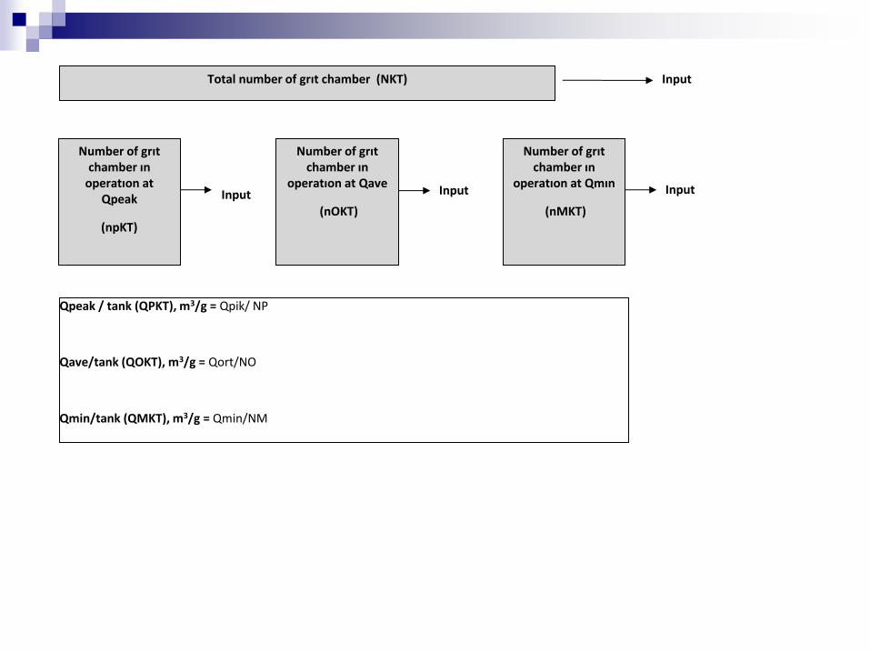
Total number of grıt chamber (NKT) Input
Number of grıt chamber ın
operatıon at Qpeak
(npKT)
Input
Number of grıt chamber ın
operatıon at Qave
(nOKT)
Number of grıt chamber ın
operatıon at Qmın
(nMKT)
Input Input
Qpeak / tank (QPKT), m3/g = Qpik/ NP
Qave/tank (QOKT), m3/g = Qort/NO
Qmin/tank (QMKT), m3/g = Qmin/NM

Herbir tankın toplam genişliği (TTW), m
Input Yağ tutma kısmı / Kum tutma kısmı (YTKT_ORAN)
Input
TTW
Herbir tankın kum tutucu kısmı genişliği(KTW), m = ttW/(ytkt_oran+1)
Herbir tankın yağ tutucu kısmı genişliği(YTW), m = KTW x ytkt_oran

TTW
Herbir tankın kum tutucu kısmı genişliği(KTW), m = ttW/(ytkt_oran+1)
Herbir tankın yağ tutucu kısmı genişliği(YTW), m = KTW x ytkt_oran

Tank uzunluğu (Ltank), m Input
Ltank= 10 x TTW
Yağ toplama kısmındaki rampa uzunluğu (YRL), m Input
Yağ toplama kısmı tank uzunluğu(Ltank_yag_toplama), m =Ltank-YRL
TTW

TTW Kum tutucu tarafı yanal derinlik(kt_yanal_d)
Kum tutucu kısmı yan duvarın yatayla yaptığı açı (kt_egimli_acı)
Kum tutucu kısmı yan duvar eğimli kısım derinliği(kt_egimli_d)
Kum toplama hunisi kum tutucu tarafı yatayla yaptığı açı (huni_acı_kt)
Kum toplama hunisi yağ tutucu tarafı yatayla yaptığı açı (huni_acı_yt)
Kum toplama hunisi derinliği(huni_d)
Kum toplama hunisi ust genislik (huni_ust_w)
Yag tutucu kısmı yan duvarın yatayla yaptığı açı(yt_egimli_acı)
Input

TTW
Kum toplama hunisi alt genislik(huni_alt_w), m
= huni_ust_w-2*(huni_d/tan(huni_acı_yt)
Yag tutucu tarafı yanal derinlik(yt_egimli_d), m
=(ktw+ytw)-(kt_egimli_d/tan(kt_egimli_acı)-huni_ust_w)*tan(yt_egimli_acı)
Yag tutucu kısmı yan duvar eğimli kısım derinliği (yt_yanal_d), m
=kt_yanal_d+kt_egimli_d-yt_egimli_d
Toplam tank derinligi (toplam_tank_d), m (kum toplama hunisi dahil)
=yt_yanal_d+yt_egimli_d+huni_d

TTW
Pik debide yag tutucu kısmı yuzey yuku (yk_yag_pik), m/sa
= (qpkt/24) / (Ltank_yag_toplama x ytw)
Ortalama debide yag tutucu kısmı yuzey yuku (yk_yag_ort), m/sa
=(qokt/24) / (Ltank_yag-toplama x ytw)
Pik debide tüm yüzey yükü (yk_tum_pik), m/sa
=(qpkt/24) / (Ltank x ttw)
Ortalama debide tüm yüzey yükü (yk_tum_ort), m/sa
=(qokt/24) / (Ltank x ttw)

TTW X=(ytw x TAN(yt_egimli_acı x Pİ()/180))
Y=(yt_egimli_d + yt_yanal_d) - (yt_yanal_d+x)
Z=y/tan(yt_egimli_acı x pi()/180)
W=kt_egimli_d/tan(kt_egimli_acı*pi()/180)
T=(ytw+ktw)-(huni_ust_w+z)

Kum tutucu yanal alanı (yanal_alan), m2
=((ktw*(kt_yanal_d+huni_d))-(y*z/2)-(kt_egimli_d*w/2))+((ytw*(yt_yanal_d+yt_egimli_d))-(y+yt_egimli_d)*t/2))
Kum toplama kısmı tank hacmi(kth), m3
=((ktw*(kt_yanal_d+huni_d))-(y*z/2)-(kt_egimli_d*w/2))*LTANK
Yağ toplama kısmı tank hacmi (yth), m3
= ((ytw*(yt_yanal_d+yt_egimli_d))-(y+yt_egimli_d)*t/2))*ltank_yag_toplama
Toplam tank hacmi (tth), m3 (kum toplama hunisi hacmi hariç)
=kth+yth
Kum toplama hunisi hacmi(hh), m3 = ((huni_alt_w+huni_ust_w)*huni_d/2)*Ltank
TTW

Hydraulic retention time at Qpeak (Tr_pik), min =( TTH / qpkt) x 24 x 60
Hydraulic retention time at QaveTr_ort), min =TR_ort=( TTH / qokt) x 24 x 60
Horizantal velocity at Qpeak (yatay_hız_pik), m/sn=(qpkt / 86400) / yanal_alan
Horizantal velocity at Qave (yatay_hız-ort), m/sn= (qokt/86400) / yanal_alan
Chosen air flow per tank (birim_hava_sarf) m3/sa/m3 tank su hacmi
Input
Air requirement per tank at Q (ave ort_hava_ihtiyacı), m3/sa = birim_hava_sarf x tth
Total air requirement (toplam_hava_ihtiyacı), m3/sa= ort_hava_ihtiyacı x nkt