entryrae - keison products · the rae systems distri utor where the monitor was purchased; they...
TRANSCRIPT

EntryRAE
User ManUal
PGM-3000Multi-Gas Monitor
046-4001-000, Revision C, January 2006

�
Read Before OperatingThis manual must �e carefully read �y all individuals who have or will have the responsi�ility of using, maintaining, or servicing this product. The product will perform as designed only if it is used, maintained, and serviced in accordance with the manufacturer’s instructions.Caution!
To reduce the risk of electric shock, turn off power before removing the monitor cover. Disconnect the battery before removing sensor modules for service. Never operate this monitor while the cover is removed. Remove monitor cover and sensor modules only in an area known to be non-hazardous.
Special Note
When the EntryRAE monitor is removed from the transport case and is turned on for the first time, there may be residual vapors trapped inside the monitor, and the initial toxic gas sensors values may indicate a few ppm. After running the monitor for several minutes in clean air, the residual vapors should clear and readings should return to near zero.
Attention! For European Applications
A. Recharge batteries in non-hazardous locations.
B . Do not connect external cable to serial interface jack in hazardous locations.
C. Use RAE Systems Charging cradle (P/N 046-3059-001) for connection to communication port and charging jack only in a non hazardous area.
Note
Only the combustible gas detection portion of this instrument has been assessed for performance in accordance with C22.2 No.152-M1984.
Seulement la partie combustible de détection de gaz de cet instrument a été evaluée pour l’exécution selon C22.2 No. 152-M1984.
Protected �y U.S. Patents 5,393,979 , 5,561,344 , 5,773,833 , 6,225,633, 6,313,638 , 6,333,632 , 6,320,388
WARNING
To prevent ignition of flammable or combustible atmospheres, disconnect power before servicing.
WARNING
Do not mix old batteries with used batteries or mix batteries from different manufacturers.
WARNING
Substitution of components may impair intrinsic safety.

c
WarningsFor safety reasons, this equipment must �e operated and serviced �y qualified personnel only. Read and understand the user manual completely �efore operating or servicing.Battery Pack
Use only RAE Systems battery packs (P/N 046-3007-000 or 046-3051-000). This instrument has not been tested in an explosive gas/air atmosphere having an oxygen concentration greater than 21%. Substitution of components may impair intrinsic safety. Recharge/replace batteries only in non-hazardous atmospheres.
Computer Interface
Do not transfer data by means of the computer interface cable in hazardous atmospheres.
Static Hazard
Clean only with a damp cloth.
Cali�ration
While the EntryRAE has been factory calibrated prior to shipment, transport and storage after leaving the factory can affect the sensors. Therefore, any newly purchased RAE Systems Instrument should be fully calibrated by exposing it to known concentration calibration gases before the instrument is put into service for the first time. For safety, check the accuracy of the monitor by exposing the sensors to calibration gas(es) before each day’s use. (Refer to “Calibration” on page 10.)
Caution!
Before each day’s usage, sensitivity must be tested on a known concentration of methane gas equivalent to 20% to 50% of full-scale concentration. Accuracy must be within 0% to +20% of actual. Accuracy may be corrected by calibration. Refer to “Calibration” on page 10.)
Long-Term Storage
Reliable performance of this gas detector is based upon regular usage. For long term storage, the battery should be disconnected. Preparation for use after long storage requires installation of the batteries and a warm-up period of at least 10 minutes for the sensors to equilibrate. The user should recognize that sensor life is based upon the purchase date.
Readings
Any rapid up-scale reading followed by a declining or erratic reading may indicate a gas concentration beyond the upper scale limit, which may be hazardous.
CAUTION: HIGH OFF-SCALE READINGS MAY INDICATE AN EXPLOSIVE CONCENTRATION!

d
AvertissementsPour des raisons de sécurité, cet équipement doit être utilisé, entretenu et réparé uniquement par un personnel qualifié. Étudier le manuel d’instructions en entier avant d’utiliser, d’entretenir ou de réparer l’équipement.Ensem�le de Batterie
Utiliser seulement de paquets batterie de RAE Systems (numéro de la pièce 046-3007-000 ou 046-3051-000). Cet instrument n’a pas été essayé dans une atmosphère de gaz/air explosive ayant une concentration d’oxygène plus élevée que 21%. La substitution de composants peut compromettre la sécurité intrinsèque. Ne charger les batteries que dans l’emplacement désigné non dangereux.
Câ�le de Computer
Connecter pas le câble externe que dans environnements non dangereux.
Danger Risque D’origine Electrostatique
Nettoyer uniquement avec un chiffon humide.
La Cali�ration
Les indications de toute instruments de RAE Systems doit être testé en exposant l’instrument à une concentration de gaz connue par une procédure diétalonnage avant de mettre en service l’instrument pour la première fois. Pour une sécurité maximale, la sensibilité du EntryRAE doit être vérifié en exposant l’instrument. (Référez la Calibration à la page 10.)
Attention!
Avant chaque utilisation journalière verifier la sensibilité avec une concentration connue de methane equivalante a 20% à 50% de la pleine échelle. La precision doit être comprise entre 0% à +20% de la valeur vraie et peut être corrigée par une procédure diétalonnage. (Référez la Calibration à la page 10.)
Stockage à Long Term
Le fonctionnement durable de ce détecteur de gas est conditionné par une utilisation régulière de celui ci. Lors d’un stockage à long terme, la batterie doit être déconnectée. Le rédémarrage aprés une longue période d’arrêt, nécessite la réinstallation de la batterie, et une période de chauffage de 10 mn afin que les capteurs se mettent à l’équilibre. L’utilisateur doit être conscient que la durée de vie indiquée pour le capteur démarre à sa date d’achat.
Les Lectures
Toute lecture rapide et positive, suivie d’une baisse subite au erratique de la valeur, peut indiquer une concentration de gaz hors gamme de détection qui peut être dangereuse.
ATTENTION: DES LECTURES SUPÉRIEURES A L’ÉCHELLE PEUVENT INDIQUER DES CONCENTRATIONS EXPLOSIVES.
e
Read Before Operating . . . . . . . . . . . . . . . . . . . . . . . . . . . . . . . . . . . . b
Warnings . . . . . . . . . . . . . . . . . . . . . . . . . . . . . . . . . . . . . . . . . . . . . . . c
Avertissements . . . . . . . . . . . . . . . . . . . . . . . . . . . . . . . . . . . . . . . . . . d
General Information . . . . . . . . . . . . . . . . . . . . . . . . . . . . . . . . . . . . . . . 1
Equipment List . . . . . . . . . . . . . . . . . . . . . . . . . . . . . . . . . . . . . . . . . . . 2
Physical Description . . . . . . . . . . . . . . . . . . . . . . . . . . . . . . . . . . . . . . 4
Display and Legend . . . . . . . . . . . . . . . . . . . . . . . . . . . . . . . . . . . . . . . 5
Operating the EntryRAE . . . . . . . . . . . . . . . . . . . . . . . . . . . . . . . . . . . 6
Turning the Monitor On . . . . . . . . . . . . . . . . . . . . . . . . . . . . . . . . . . 6
Warm-up Sequence . . . . . . . . . . . . . . . . . . . . . . . . . . . . . . . . . . . . 6
Turning the Monitor Off . . . . . . . . . . . . . . . . . . . . . . . . . . . . . . . . . . 7
Monitor Mode . . . . . . . . . . . . . . . . . . . . . . . . . . . . . . . . . . . . . . . . . 8
The Pump Cycle . . . . . . . . . . . . . . . . . . . . . . . . . . . . . . . . . . . . . . . 8
Continuous Operation of the Pump . . . . . . . . . . . . . . . . . . . . . . . . . 8
Detecting Gases and Vapors Real-time . . . . . . . . . . . . . . . . . . . . . 8
Calibration . . . . . . . . . . . . . . . . . . . . . . . . . . . . . . . . . . . . . . . . . . . . . 10
Calibration Equipment . . . . . . . . . . . . . . . . . . . . . . . . . . . . . . . . . . 10
Calibration Procedure . . . . . . . . . . . . . . . . . . . . . . . . . . . . . . . . . . 10
Optional Step: Zero Calibration for the Oxygen Sensor . . . . . . . . 14
Calibration Period . . . . . . . . . . . . . . . . . . . . . . . . . . . . . . . . . . . . . 15
EntryRAE Usage Overview . . . . . . . . . . . . . . . . . . . . . . . . . . . . . . . . 16
Alarm Signals . . . . . . . . . . . . . . . . . . . . . . . . . . . . . . . . . . . . . . . . 17
Testing Alarm Signals . . . . . . . . . . . . . . . . . . . . . . . . . . . . . . . . . . 17
Alarm Conditions . . . . . . . . . . . . . . . . . . . . . . . . . . . . . . . . . . . . . . 18
Preset Alarm Limits and Calibration . . . . . . . . . . . . . . . . . . . . . . . 18
Back Light . . . . . . . . . . . . . . . . . . . . . . . . . . . . . . . . . . . . . . . . . . . 18
Sampling Pump . . . . . . . . . . . . . . . . . . . . . . . . . . . . . . . . . . . . . . . 19
Datalogging . . . . . . . . . . . . . . . . . . . . . . . . . . . . . . . . . . . . . . . . . . 19
Charging the EntryRAE . . . . . . . . . . . . . . . . . . . . . . . . . . . . . . . . . 19
Ta�le of Contents

f
The Li-Ion Battery Pack . . . . . . . . . . . . . . . . . . . . . . . . . . . . . . . . . 21
Programming Mode . . . . . . . . . . . . . . . . . . . . . . . . . . . . . . . . . . . . . . 21
Security . . . . . . . . . . . . . . . . . . . . . . . . . . . . . . . . . . . . . . . . . . . . . 21
Programming Menus . . . . . . . . . . . . . . . . . . . . . . . . . . . . . . . . . . . 22
Entering Program Mode . . . . . . . . . . . . . . . . . . . . . . . . . . . . . . . . 23
Change Monitor Setup . . . . . . . . . . . . . . . . . . . . . . . . . . . . . . . . . 23
Maintenance . . . . . . . . . . . . . . . . . . . . . . . . . . . . . . . . . . . . . . . . . . . 27
Replacing the Li-Ion Battery Pack . . . . . . . . . . . . . . . . . . . . . . . . . 27
Emergency Alkaline Battery Adapter . . . . . . . . . . . . . . . . . . . . . . . 29
Sensor Replacement . . . . . . . . . . . . . . . . . . . . . . . . . . . . . . . . . . 30
CO Sensor Charcoal Filter . . . . . . . . . . . . . . . . . . . . . . . . . . . . . . 32
Cleaning the PID . . . . . . . . . . . . . . . . . . . . . . . . . . . . . . . . . . . . . . 33
Setting Pump Stall Threshold . . . . . . . . . . . . . . . . . . . . . . . . . . . . . . 34
Specifications . . . . . . . . . . . . . . . . . . . . . . . . . . . . . . . . . . . . . . . . . . 35
Certifications . . . . . . . . . . . . . . . . . . . . . . . . . . . . . . . . . . . . . . . . . 36
Sensor Range and Resolution . . . . . . . . . . . . . . . . . . . . . . . . . . . 36
Service and Repair Record . . . . . . . . . . . . . . . . . . . . . . . . . . . . . . . . 37
SPECIAL NOTE: If the monitor needs to be serviced, contact either:
The RAE Systems distri�utor where the monitor was purchased; they will return the monitor on your behalf,
or
The RAE Systems Technical Service department. Before returning the monitor for service or repair, obtain a Returned Material Authorization (RMA) number for proper tracking of your equipment. This number needs to be on all documentation and posted on the outside of the box in which the monitor is returned for service or upgrade. Packages without RMA Numbers will be refused at the factory.

General Information 1
General Information
The EntryRAE is a 4-gas plus PID (photoionization detector) gas moni-tor. Reliable, easy to operate and simple to calibrate, the EntryRAE delivers added protection without added complexity.
Simple, Modular, Dura�le PID
RAE Systems is the technology leader in PIDs. Our modular, plug & play, self-cleaning (patented) PID is the most reliable and durable PID available today.
Key Features
• Reliable self-cleaning PID• Also includes CO, H2S, LEL and O2 sensors• Built-in pump • Ιnterchangeable Li-Ion and alkaline battery adapter• Up to 16 hours of continuous operation• Large, easy-to-read display• Datalogging• Visual alarm with bright red flashing LEDs• Loud audible alarms (95dB at 30 cm)• Rugged weather-resistant composite case

2 General Information
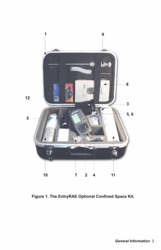
Equipment ListPhoto Item
Num�er Part Name Part Num�er
Monitor Only*Shipping case
2 Monitor 701-3040-000Sensors
Photoionization Detector 023-0102-000Oxygen (O2) 046-1161-000Combustible (%LEL, %Vol) 014-0212-000Carbon Monoxide (CO) 032-0200-000Hydrogen Sulfide (H2S) 032-0202-000
Rechargeable Li-Ion Battery 046-3007-000
3Charging Cradle
- 120 V AC to 12 V DC wall charger, US plug or- 230 V AC to 12 V DC wall charger, Euro plug
046-3059-000500-0036-000500-0036-001
4 Alkaline Battery Adapter 046-3051-0005 Calibration Adapter/Tubing Assembly 046-3040-000
7External Filters (5-pack) 046-3022-005Charcoal Filters (for the CO Sensor) 008-3006-005
8 User Manual 046-4001-00012 EntryRAE Resource CD 046-4013-000
Computer Interface Cable - RS232 to RS232 with USB adapterOptional Confined Space Kit II (CSK II) 046-0911-000
1 Hard Transport Case with precut foam 002-3009-000
9 Remote Sampling Probe with 15 feet (5 meters) of self-coiling Teflon (tm) tubing 008-3015-002
5 Tool Kit 081-0005-000
10 Four-Gas Mix in a 34-Liter cylinder (50% LEL, 20.9% O2, 10 ppm H2S, 50 ppm CO) 600-0050-004
11 100 ppm Isobutylene Gas in a 34 L cylinder 600-0002-0006 Regulator (male) with tubing 007-3021-0006 Regulator (female) with tubing 002-3011-000
Optional Guaranteed Cost of Ownership4-year repair and replacement guarantee SVC-PTC4-046Optional Accessories (items sold separately)
not shown AutoRAE Docking Station Starter Kit 048-5900-000not shown Additional AutoRAE Cradle 048-0154-000not shown PID Cleaning Kit 500-0014-010
* Different shipping cases are used for monitor-only and calibration kits.
General Information 3
1
8
55, 6
10 7 2 4 11
9
123
Figure 1. The EntryRAE Optional Confined Space Kit.

4 General Information
Physical Description1. Display2. Operation / Program keys3. Charge status4. Visual alarm5. Gas plate6. Buzzer7. Gas inlet with external filter8. Charging contacts9. Charging cradle10. Power jack11. RS-232 port
9
7
11
4
5
6
8
2
1
103
bottom of monitor
Figure 2. EntryRAE and Charging Cradle.
monitor in cradle
General Information 5
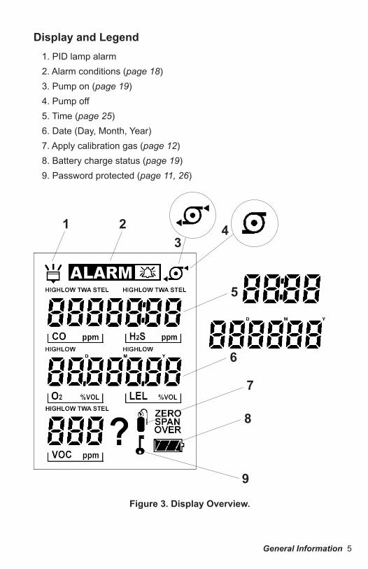
Display and Legend1. PID lamp alarm 2. Alarm conditions (page 18)3. Pump on (page 19)4. Pump off5. Time (page 25)6. Date (Day, Month, Year)7. Apply calibration gas (page 12)8. Battery charge status (page 19)9. Password protected (page 11, 26)
7
4
5
6
213
9
8
Figure 3. Display Overview.
6 Operating the EntryRAE
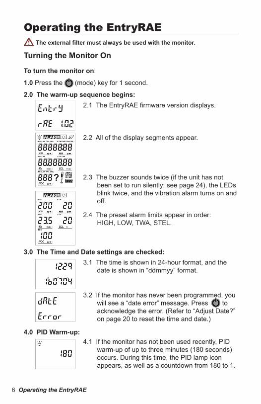
3.1 The time is shown in 24-hour format, and the date is shown in “ddmmyy” format.
3.2 If the monitor has never been programmed, you will see a “date error” message. Press @ to acknowledge the error. (Refer to “Adjust Date?” on page 20 to reset the time and date.)
3.0 The Time and Date settings are checked:
Operating the EntryRAEThe external filter must always �e used with the monitor.
Turning the Monitor On
2.1 The EntryRAE firmware version displays.
2.2 All of the display segments appear.
2.3 The buzzer sounds twice (if the unit has not been set to run silently; see page 24), the LEDs blink twice, and the vibration alarm turns on and off.
2.4 The preset alarm limits appear in order: HIGH, LOW, TWA, STEL.
To turn the monitor on:
1.0 Press the @ (mode) key for 1 second.
2.0 The warm-up sequence �egins:
4.0 PID Warm-up:4.1 If the monitor has not been used recently, PID
warm-up of up to three minutes (180 seconds) occurs. During this time, the PID lamp icon appears, as well as a countdown from 180 to 1.

Operating the EntryRAE 7
5.1 Cali�ration NeededThis message appears if the number of days since the last calibration is greater than the “Cal Due Day” setting. (Refer to “Calib Due Day?” in the Calibration section on page 24.)NOTE: If the Time and Date are invalid or were recently updated, then calibration is automatically due. Press @ to acknowledge the message.
6.1 Perform a fresh air calibration before each use.6.2 The monitor must be in clean ambient air during
fresh air calibration.
6.3 Press Y and the calibration begins. The display counts down from 5 to 0 (6 seconds), at which time the process is complete.
6.4 “Cal Updating.” The calibration data is updated, the monitor warm-up is complete, and the EntryRAE is in Monitor Mode.
5.0 The date of the last cali�ration is checked:
6.0 A Fresh Air Cali�ration is requested
1.0 Press the @ button for 5 seconds.
Turning the Monitor OffThe monitor cannot be turned off until after the warm-up sequence is completed.
To turn the monitor off:
1.1 The display counts down from 3 to 1 (3 seconds), and flashes the LED for each count.
1.2 Release @ when “Unit Off” appears on the display.

8 Operating the EntryRAE
Monitor ModeIn Monitor Mode, the EntryRAE samples the environment and displays real-time readings for each enabled sensor.
The Pump CycleUnder normal operating conditions, when the monitor is not in an alarm state, the pump cycles on and off about every 8 seconds. This on/off cycle improves the reliability of the PID and saves battery life.
The pump runs continuously when:
1.0 The concentration of any measured gas or vapor triggers an alarm condition.
2.0 When the concentration of VOCs is nearing an alarm condition.
Continuous Operation of the PumpPressing the Y key and the N key simultaneously causes the pump to run continuously for 5 minutes. This value can be changed using the ProRAE Studio software.
Detecting Gases and Vapors Real-timeCAUTION: HIGH OFF-SCALE READINGS MAY INDICATE AN EXPLOSIVE CONCENTRATION.
ATTENTION: LES LECTURES HORS ÉCHELLE ÉLEVÉES PEUVENT INDIQUER UNE CONCENTRATION EXPLOSIVE.

Operating the EntryRAE 9
In Monitor Mode, the EntryRAE samples the environment and displays the current measured readings for each enabled sensor.
It also calculates and stores the High, Low, STEL and TWA for the sensors. Press @ to scroll through these readings:
STEL - The Short Term Exposure Limit for CO, H2S, and VOC gases only; the average reading of the gas concentration for the last 15 minutes, which is updated every minute. Dashes (“- - -”) appear for the first 15 minutes.
TWA - The Time Weighted Average for CO, H2S, and VOC gases only; the accumulated reading of the gas concentration since the monitor was turned on, divided by 8 hours. Updated every minute.
LOW – The lowest reading for each gas concentration since the monitor was turned on; updated every second. Press Y to reset the minimum values.
HIGH - The highest reading for each gas concentration since the monitor was turned on; updated every second. Press Y to reset the high values.

10 Operating the EntryRAE
1.0 The monitor must �e in Programming Mode for cali�ration.
1.1 Press and hold @ and N for 3 seconds to enter Programming.
1.2 Password Ena�led Monitors.
CalibrationWhile EntryRAEs are cali�rated prior to leaving the factory, temperature extremes and/or shocks during shipment can cause sensor drift. Therefore, the accuracy of any newly purchased RAE Systems monitor should �e tested �y exposing the sensor(s) to known concentration cali�ration gas �efore the monitor is used or put into service. For maximum safety, the accuracy of the monitor should �e checked �y exposing the sensor(s) to known concentration cali�ration gas �efore each day’s use.
Les indications de toute instruments de RAE Systems doit être testé en exposant l’instrument à une concentration de gaz connue par une procédure dietalonnage avant metre en service l’instrument pour la première fois. Pour une sécurité maximale, la sensi�ilité du EntreRAE doit être vérifie en exposant l’instrument à une concentration de gaz connue par une procédure diétalonnage avant chaque utilisation journaliere.
Information regarding sensor expiration is listed in Technical Note TN-114, availa�le at www.raesystems.com.
Cali�ration EquipmentThe sensors are calibrated using both fresh air and calibration (span) gas. The EntryRAE span gas mixtures are fixed. To calibrate an EntryRAE, the following items are needed:
A. A cylinder of four-gas mix containing: 50% LEL methane 20.9% O2
10 ppm H2S 50 ppm CO
B. A cylinder of 100 ppm isobutylene.C. A calibration adapter to connect the monitor to the outlet of the gas
cylinder.
Cali�ration ProcedureThe calibration procedure is broken down into three steps. All steps should be performed whenever calibration is needed.
Step One: Enter Programming Mode

Operating the EntryRAE 11
1.2.1 If a password is enabled, you are prompted to enter one.
1.2.2 Use Y to increase the digit and N to decrease the digit.
1.2.3 Use @ to move to the next digit.1.2.4 Press @ and Y to enter the password.1.2.5 If the password is incorrect, the monitor
returns to Monitor mode.
2.1 Press Y and the calibration begins. The display counts down from 5 to 1 (5 seconds), at which time the process is complete.
2.2 Cali�ration UpdatingThe monitor is in the process of calibrating the sensors. As it completes, the display shows the sensors registering zero (or 20.9% for O2), before it moves to the next step, “Span Cal?”
Using External Zeroing Organic FiltersUse an external zero organic filter (P/N 008-3024-000, 3-pack) if the ambient air may be contaminated with hydrocarbons. Attach the filter to the EntryRAE during fresh air calibration. The filter can be used up to 20 times before disposing. This filter removes most heavier organic and inorganic compounds, but may not completely remove lighter compounds such as methane, propane and CO. Note that the filter should be attached to the EntryRAE before the calibration adapter.
Step Three: Span Gas Cali�ration for Multiple Sensors
3.0 For this calibration step, the LEL, CO and H2S sensors are calibrated using the 4-gas mix (P/N 600-0050-004).
Step Two: Fresh Air Cali�ration
The monitor must be in clean ambient air during fresh air calibration.
12 Operating the EntryRAE
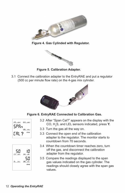
3.1 Connect the calibration adapter to the EntryRAE and put a regulator (500 cc per minute flow rate) on the 4-gas mix cylinder.
3.2 After “Span Cal?” appears on the display with the CO, H2S, and LEL sensors indicated, press Y.
3.3 Turn the gas all the way on.3.3 Connect the open end of the calibration
adapter to the regulator. The monitor starts to countdown from 70 seconds.
3.4 When the countdown timer reaches zero, turn off the gas, and disconnect the calibration adapter from the regulator.
3.5 Compare the readings displayed to the span gas values indicated on the gas cylinder. The readings should closely agree with the span gas values.
Figure 6. EntryRAE Connected to Cali�ration Gas.
Figure 5. Cali�ration Adapter.
Figure 4. Gas Cylinded with Regulator.

Operating the EntryRAE 13
Step Four: Span Gas Cali�ration for the PID Sensor
4.1 The final step is to calibrate the PID sensor.4.2 Connect the EntryRAE calibration adapter to the monitor (see Figure
6) and put a regulator (500 cc per minute flow rate) on the cylinder of isobutylene.
4.3 Connect the open end of the calibration adapter to the regulator.
3.6 If calibration fails, the monitor briefly displays “Err” above each failed sensor. NOTE: Stop calibration in the event that the gas runs out or is disconnected. To interrupt calibration, press @ . When calibration stops, the sensors revert to their previous calibration values.
3.7 After briefly displaying the concentration, the monitor moves on to calibrating the PID.
4.4 When “Span Cal?” appears on the display with the VOC sensor indicated, press Y and turn the gas all the way on. The monitor counts down from 30 seconds.
4.5 Turn off the gas, dicsconnect from the adapter, and remove the calibration adapter from the monitor.If the calibration fails, the monitor briefly displays “Err” above the failed sensor.NOTE: Stop calibration if the gas runs out or is disconnected. To interrupt calibration, press @. When calibration stops, the sensors revert to their previous calibration values.
14 Operating the EntryRAE
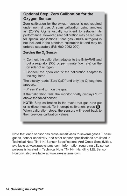
Optional Step: Zero Cali�ration for the Oxygen SensorZero calibration for the oxygen sensor is not required under normal use. A span calibration using ambient air (20.9% O2) is usually sufficient to establish its performance. However, zero calibration may be required for special applications. Zero gas (100% nitrogen) is not included in the standard calibration kit and may be ordered separately (P/N 600-0062-000).
Zeroing the O2 Sensor
Connect the calibration adapter to the EntryRAE and put a regulator (500 cc per minute flow rate) on the cylinder of nitrogen. Connect the open end of the calibration adapter to
the regulator.The display reads “Zero Cal?” and only the O2 segment appears. Press Y and turn on the gas.If the calibration fails, the monitor briefly displays “Err” above the failed sensor.NOTE: Stop calibration in the event that gas runs out or is disconnected. To interrupt calibration, press @ . When calibration stops, the sensors will revert back to their previous calibration values.
Note that each sensor has cross-sensitivities to several gases. These gases, sensor sensitivity, and other sensor specifications are listed in Technical Note TN-114, Sensor Specifications And Cross-Sensitivities, available at www.raesystems.com. Information regarding LEL sensor poisons is located in Technical Note TN-144, Handling LEL Sensor Poisons, also available at www.raesystems.com.
Operating the EntryRAE 15
After the optional zero calibration for the O2 sensor, “Calib due day?” is displayed. Press Y to set a new date, or N to skip.
When setting a new day, Y increases the digit, N decreases the digit, and @ moves to the next digit. After the third digit is set, the question mark (“?”) blinks. Press Y to accept the changes. Press N to discard the changes. Press @ to change the due date.
Cali�ration PeriodThe EntryRAE should have a fresh air calibration before each use and should be fully calibrated:
no less than every 30 days if it does not pass a fresh air reading if it does not pass a field calibration.

16 Operating the EntryRAE
Confined Space Pre-Entry Test
It is important to always test the atmosphere inside a confined space before entering. Be aware of any hazardous chemicals you may be bringing into the space. Remember that many cleaners, paints, adhesives, degreasers and other modern industrial products (even treated wood) contain volatile organic compounds that may be hazardous to your health and safety.
Test the atmosphere in the confined space by sampling air at three levels (top, middle and bottom) in the confined space. Give the instrument time to sample the gas at each level - the correct sampling time is 60 seconds plus 1 second for every foot of tubing.
Alarms
If there are any gas ALARMS at any level in the confined space, that space is not safe. DO NOT ENTER! Identify the alarm condition and then start your preventive actions according to your company’s confined space entry procedures.
No Alarms
If there are no alarms, the confined space may be safe to enter. Disconnect the tubing before carrying the EntryRAE into the confined space. If monitoring is to be done by a confined space attendant, they should continue to monitor while you enter the area. If the monitor alarms and “BAT” is displayed, the battery needs to be charged: There are 15 minutes
Storage
Always keep the EntryRAE on its charging cradle in a dry indoor area when it is not in use. See page c for long-term storage warnings and procedures.
EntryRAE Usage OverviewAfter the EntryRAE is warmed up, calibrated, and charged, it is ready for use to enhance your personal safety.
CAUTION: HIGH OFF-SCALE READINGS MAY INDICATE AN EXPLOSIVE CONCENTRATION.

Operating the EntryRAE 17
Alarm SignalsWhen an alarm condition occurs, the monitor provides audible, visible and vibration alarms to alert users of unsafe conditions.
Auto Reset and Latched AlarmThe EntryRAE comes from the factory with “Auto Reset Alarm” turned on. This means that the alarms cease when the alarm condition is no longer present. Alternatively, this feature can be changed and set up as a “Latched Alarm.” When the alarm system is “Latched,” Y must be pressed to acknowledge the alarm condition and to reset the alarms.
The Auto Reset function does not automatically reset if a sensor fails calibration and goes into alarm. The sensor must be successfully calibrated in order to clear this alarm.
Testing Alarm SignalsPress Y while in monitoring mode. If the alarm is functional, the buzzer beeps once (if the monitor is not set to run silently; see page 24), the alarm LED flashes once, and the vibration alarm turns on and off.
Press the @ button for 5 seconds.
The display counts down from 3 to 1 (3 seconds). Release @ when “Unit Off” appears on the
display.
Return the EntryRAE to the dry, indoor storage area and put it in its charger.
or less of run time remaining. Leave the Confined Space immediately! (Refer to the Applications and Technical Notes Guide, P/N 000-4001-000, for more information regarding confined space entry and other applications.)
After Usage
18 Operating the EntryRAE
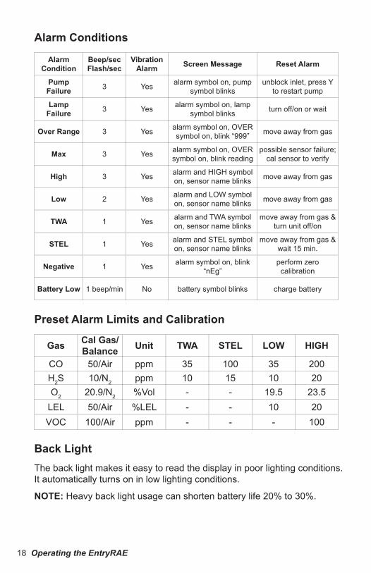
Alarm Conditions
Alarm Condition
Beep/secFlash/sec
Vi�ration Alarm Screen Message Reset Alarm
Pump Failure 3 Yes alarm symbol on, pump
symbol blinksunblock inlet, press Y
to restart pump
Lamp Failure 3 Yes alarm symbol on, lamp
symbol blinks turn off/on or wait
Over Range 3 Yes alarm symbol on, OVER symbol on, blink “999” move away from gas
Max 3 Yes alarm symbol on, OVER symbol on, blink reading
possible sensor failure; cal sensor to verify
High 3 Yes alarm and HIGH symbol on, sensor name blinks move away from gas
Low 2 Yes alarm and LOW symbol on, sensor name blinks move away from gas
TWA 1 Yes alarm and TWA symbol on, sensor name blinks
move away from gas & turn unit off/on
STEL 1 Yes alarm and STEL symbol on, sensor name blinks
move away from gas & wait 15 min.
Negative 1 Yes alarm symbol on, blink “nEg”
perform zero calibration
Battery Low 1 beep/min No battery symbol blinks charge battery
Preset Alarm Limits and Cali�ration
Gas Cal Gas/Balance Unit TWA STEL LOW HIGH
CO 50/Air ppm 35 100 35 200H2S 10/N2 ppm 10 15 10 20O2 20.9/N2 %Vol - - 19.5 23.5
LEL 50/Air %LEL - - 10 20VOC 100/Air ppm - - - 100
Back LightThe back light makes it easy to read the display in poor lighting conditions. It automatically turns on in low lighting conditions.
NOTE: Heavy back light usage can shorten battery life 20% to 30%.

Operating the EntryRAE 19
Sampling PumpUnder normal operating conditions, when the monitor is not in an alarm state, the pump cycles on and off about every eight seconds. This on/off cycle improves the reliability of the PID and saves battery life. Press the Y key and the N key simultaneously and the pump will run continuously for five minutes. The pump also runs continuously when:
1.0 The concentration of any measured gas or vapor triggers an alarm condition.
2.0 The concentration of VOCs approaches alarm conditions.
The monitor can detect any obstructions in the external filter that causes a pump stall. The alarm activates and the pump symbol blinks in the upper right corner of the display. Clear the obstruction.
Press Y to start the pump again.
DataloggingDatalogging occurs automatically for all enabled sensors at one-minute intervals, allowing five days' continuous data storage. When the end of the storage memory is reached, the monitor automatically wraps around to the beginning of the log and overwrites the oldest stored data.
NOTE: Datalogging pauses when the monitor goes into Programming Mode.
Charging the EntryRAEThe battery charge is indicated on the EntryRAE screen by the battery charge status icon on the monitor’s LCD. When the icon’s segments are filled in, the battery is charged. As the battery is discharged, the segments disappear, indicating that the unit should be charged before use. Refer to “Maintenance” for instructions on changing/removing the battery.
The Li-Ion battery pack can be charged alone or while it is installed in the monitor. To charge an installed battery, simply plug the transformer into the cradle and into an AC electrical outlet. Place the monitor in the cradle. The monitor (or battery) is fully charged when:The monitor (or battery) is fully charged when:
The LED on the charging cradle is green The “Fully Charged” message appears on the display The segments of the battery icon are blinking.

20 Operating the EntryRAE
Figure 7. Contacts on the �attery pack.
To charge the battery pack alone, place the battery pack on the charging cradle, matching the contacts on the battery pack to the contacts on the charging cradle.
Figure 6. Installing the �attery pack into the charging cradle.
The monitor (or battery) is still in charging mode when:
The LED on the charging cradle is red The “Monitor Charging” message appears on the display The segments of the battery icon are scrolling.

Programming Mode 21
The Li-Ion Battery PackThe factory-supplied Li-ion battery pack is designed to last for 16 hours of normal operation between charges (without alarm or back light conditions). The rechargeable batteries have a 1-year warranty. Age, ambient temperature, and heavy usage may impact battery life.
Battery packs slowly drain even if the monitor is turned off. Therefore, it is strongly recommended that the EntryRAE be stored on its charging cradle. The battery can trickle-charge when not in use.
If the battery packs have not been charged for 10 days, the battery voltage will be low. Fully charge battery packs before going into the field, and recharge them upon returning from the field.
To reduce the risk of ignition of hazardous atmospheres, recharge �attery only in areas known to �e non-hazardous. Remove and replace �attery only in areas known to �e non-hazardous.
Ne charger les �atteries que dans emplacement désignes non dangereux.
Programming ModeIn addition to calibration, authorized users may change the monitor settings to their requirements using the Programming Mode.
Note: Monitoring gas concentrations pauses during Programming Mode and during calibration. Datalogging also pauses during Programming Mode, but resumes when programming is finished.
SecurityEntryRAE provides the option of securely enabling a password to access Programming Mode. The default password is “0000.” To enable password access, change the “0000” to a desired password. (Refer to “Change Pass?” on page 26.)

22 Programming Mode
Programming Menus

Programming Mode 23
Entering Program Mode1. Press @ and N together until the first program
menu, “Fresh Air Calibration?” appears.2. Press N to cycle through the submenu options.3. Press Y to enter a submenu.4. To modify a value, use Y to increase and N to
decrease. 5. Use @ to move from character to character and/or
from sensor to sensor.6. When the “?” appears at the bottom of the display,
press Y to save changes (or N to cancel changes) and exit the submenu.
7. To discard changes or exit the Programming Mode, press @ to return to the Reading Display.
Change Monitor SetupThe following submenus represent the programmable setup of the monitor.
Fresh Air Cali�ration? Refer to “Fresh Air Calibration” on page 11.
Span Cali�ration CO, HCO, H2S, LEL?? Refer to “SpanRefer to “Span Gas Calibration for Multiple Sensors” on page 11 to calibrate the CO, H2S and LEL sensors.

24 Programming Mode
Span Cali�ration VOC? Refer to “Span Gas Calibration for the PID Sensor” on page 13.
Zero Cali�ration? Refer to “Zero Calibration for the Oxygen Sensor” on page 14.
Cali� Due Day? Use this feature to set a reminder to calibrate regularly. Enter the number of days between calibrations per your company’s standards. After 30 days of no calibration, the monitor sounds. Once the monitor is calibrated, the counter resets.
Set Type? Choose either automatic alarm reset or latched (constant) alarm. To acknowledge and reset a latched alarm, press Y.
Set Run Silent? Press Y to let the monitor run in silent mode. In this mode, the audible alarm does not sound during alarm conditions.
Press N to let the audible alarm sound during alarm conditions.
Adjust Alarm Limits?HIGH - The highest reading for each gas concentration since the monitor was turned on; updated every second.
Press Y to reset the high values.

Programming Mode 25
LOW – The lowest reading for each gas concentration since the monitor was turned on, updated every second. Press Y to reset the minimum values.
TWA - The Time Weighted Average for CO, H2S, and VOC gases only; the accumulated reading of the gas concentration, divided by 8 hours, since the monitor was turned on. Updated every minute.
STEL - The Short Term Exposure Limit for CO, H2S, and VOC gases only; the average reading of the gas concentration for the last 15 minutes, which is updated every minute. Dashes “- - -” appear in the display for the first 15 minutes.
Ena�le/Disa�le Sensor? Enable or disable sensor(s); a disabled sensor does not measure or display the gas concentration. Use this if a sensor has failed or is providing erroneous readings. Use @ to move from sensor to sensor. “Yes” means the sensor is enabled; likewise, “No” means the sensor is disabled. Press Y to enable or press N to disable.
Adjust Date? Set the date and time using the standard 24-hour format.

26 Programming Mode
Change Pass? (Password) Set a four-digit password, which is used to access Programming Mode. (Refer to “Security” on page 21.)
Secure Beep? If “yes,” a security beep sounds every minute when the monitor is on.
Set LEL Unit? The EntryRAE provides the option of displaying the concentration of combustibles gases in %LEL or %Vol.

Maintenance 27
MaintenanceReplacing the Li-Ion Battery Pack
To reduce the risk of ignition of hazardous atmospheres, recharge the �attery only in areas known to �e non-hazardous. Remove and replace the �attery only in areas known to �e non-hazardous.
Ne charger les �atteries que dans emplacements désignes non dangereux.
Do not use the �attery outside the operating temperature range of -4º to 122º F / -20º to 50º C (UL/cUL) or -4º to -116º F / -20º to 47º C (ATEX).
Ne faites aucune utilisation l’extérieur de �atterie la gamme de température de fonctionnement entre -4º à 122º F / -20º à 50º C (UL/cUL) or -4º à -116º F / -20º à 47º C (ATEX).
Do not store the �attery outside the temperature range of -4º to 122º F (-20º to 50º C).
Ne faites aucune magasin la �atterie en dehors de la température entre -4º à 122º F (-20º à 50º C).
The battery compartment is located on the back of the monitor.
Remove the battery compartment cover by loosening the three case screws with a screwdriver or a coin.
case screws for battery compartment
Figure 8. Battery Compartment Screw Locations

28 Maintenance
Remove the battery pack from the monitor.
Replace the battery compartment cover and tighten the screws.
The spent battery pack may be charged on the charging cradle by itself. (Refer to “Charging the Li-Ion Battery Pack” on page 19.)
Figure 9. Removing the Battery Pack Cover.
Figure 10. Removing the Li-Ion Battery Pack.

Maintenance 29
Use the adapter when there isn't time to recharge the Li-Ion battery pack. The adapter (P/N 046-3051-000) accepts four AA alkaline batteries (use only Duracell MN1500 or Energizer 91) to provide approximately 12 to 14 hours of operation.
Remove the Li-Ion battery pack from the monitor.
Install four AA alkaline batteries into the battery
Emergency Alkaline Battery Adapter
adapter, making sure the battery polarity is correct.
Replace the battery cover and tighten the screws.
The monitor automatically detects the alkaline batteries.
Figure 11. Installing the Alkaline Battery Pack.

30 Maintenance
Sensor Replacement Under normal operating conditions, most sensors lose their original sensitivity after the expected operating life and need to be replaced.
Warranties: The oxygen (O2), combustible gas (LEL), hydrogen sulfide (H2S) and carbon monoxide (CO) sensors all have a 2-year warranty. The PID sensor has 1 year warranty.
Replace a sensor when it fails to calibrate.
The sensors are located inside the front of the monitor.
See Technical Note TN-114, Sensor Specifications And Cross-Sensitivities, for additional information, available at www.raesystems.com.
PID
H2S
O2
LEL
CO
Figure 12. Sensor Locations.

Maintenance 31
To replace a sensor:
1. Turn the monitor off.2. Remove the front sensor cover by
loosening the two screws on the back of the monitor below the battery cover. See Figure 13.
3. Push the screws from the back of the monitor to pop the cover off the front (Figure 14).
4. Using the sensor puller, remove the sensor by carefully pulling straight out (Figure 15).The colored dots marked next to each sensor socket should match the color of the sensors.
5. To install new sensors, re-align the dots on the sensors with the dots on the monitor.
6. Press the sensors all the way into the socket.
7. Replace the monitor cover and tighten the screws in the back.
Figure 13. Loosening rear screws.
Figure 15. Using sensor puller to handle sensor.
Figure 14. Pushing screws to remove sensor cover.

32 Maintenance
8. Turn the monitor on and the newly installed sensors should be properly identified by the EntryRAE in the start-up screen. Let the monitor run for 15 minutes before calibration.
9. Calibrate all sensors prior to use.
CO Sensor Charcoal FilterThe carbon monoxide (CO) sensor may be sensitive to hydrocarbons, so use a charcoal filter (P/N 008-3006-005) to reduce or eliminate organic vapor contamination or cross-sensitivity. The charcoal filter is installed in the gas plate above the CO sensor. Under normal operation conditions, the charcoal filter lasts from four to six weeks before it needs to be replaced. If the monitor has been exposed to high concentrations of VOC gases for a prolonged period of time, the carbon filter needs to be replaced more frequently.
Place the carbon filter above the CO sensor on the gas plate.
NOTE: The CO charcoal filter lowers the reading if it is accidentally used on other sensors.
Figure 16. CO and charcoal filter locations.
CO Sensor
Charcoal filter location

Maintenance 33
Cleaning the PIDIf the PID does not calibrate, it may need to be cleaned. Be sure to use the specially shaped swab included in the PID Cleaning Kit (p/n 500-0014-010), shown in the Equipment List, to clean the PID.1. Open the sensor compartment.2. Remove sensor with sensor puller (follow procedure on page 31).3. Using a swab, drip a little bit methanol on the lamp window through
the openings on the top of the PID.4. Use the swab to carefully clean the lamp window through the two
openings.5. Leave the PID to dry by itself for five minutes.
Figures 19. Cleaning the PID.
Pump ReplacementThe pump in the EntryRAE is not field replaceable. Call RAE Systems Technical Support or an authorized service center when the pump needs to be replaced.

34 Maintenance
Setting Pump Stall ThresholdNote: This section should only be used by authorized technical users. Monitoring continues while EntryRAE is in Diagnostic Mode.
Diagnostic mode allows users to set the pump stall setpoint. This should only be done if your EntryRAE is going into a pump alarm when the pump is not blocked, or if the EntryRAE does not go into pump alarm when you block the pump inlet by holding your finger over it.
Entering Diagnostic Mode
1. Press @ and Y simultaneously until the first diagnostic screen blanks. Then release the keys and the values reappear.
2. Press @ 7 times to cycle through the diagnostic screens until you reach the pump diagnostic screen. The first, CO, H2S, O2, LEL, VOC, and run time screens are used for factory operation and testing only. The pump diagnostic screen displays a high and low pump rate. The first digit of the last number blinks.
3. To set the pump stall alarm, write down the “Hi” value as found, and then block the pump inlet while the pump is running (about 5 seconds), until the “Hi” reading stabilizes.
4. Write down the new “Hi” value. Add the two “Hi” values together, and then divide by two to get the average value.
5. Enter the average into the bottom number on the screen using the Y and N keys to increase and decrease the digits, and @ to move between digits.
6. Once the average is entered, press @ until you see the blinking “?”. Press Y to save the pump stall threshold value.
7. Exit the diagnostic mode by pressing @ and Y together until the screen changes. Gas readings may take a second to appear.

Specifications 35
SpecificationsSize 5.9" L x 3.3" W x 1.9" H (15 x 8.5 x 1.9 cm) without clip
Weight 20 oz with battery (567 g) and clipSensors (5) Protected catalytic bead for combustible gases
Electrochemical sensors for oxygen and toxic gasesPhotoionization detector for VOC broadband detection using 10.6 eV lamp
Battery Drop-in rechargeable Li-ion battery packStandard alkaline battery adapterCharging cradle doubles as external battery changer
Operating Hours 16 hours continuous with Li-ion (typical), 12 hours with alkalineBattery Operation
Temperature-4º to 122º F (-20º to 50º C) UL/cUL -4º to 116º F (-20º to 47º C) ATEX
Battery Storage Temperature
-4º to 122º F (-20º to 50º C)
Display Large 1.4" x 1.8" (3.5 x 4.5 cm) segmented display with LED back lightKeypad Three-button operation
Direct Readout Instantaneous for 5 values:Oxygen as percentage by volumeCombustible gas as %LEL or %VolVOCs, CO and H2S as parts per millionTWA and STEL values for VOCs, CO and H2SHigh and low values for all gasesBattery life displayed as icon in 1/4 increments
Alarms Audible: 95dB at 30 cmVisible: Bright LED bar visible from top, front and sidesSensory: Built-in vibration alarmHigh: 3 beeps and flashes per secondLow: 2 beeps and flashes per secondSTEL and TWA: 1 beep and flash per secondLow battery displays empty battery symbol, beep per second
EMI/RFI Highly resistant to EMI/RFI. Compliant with EMC directive 89/336/EECIP Rating IP-55: protected against dust, protected against low pressure jets of
water from all directionsDatalogging Wrapping 120 hours (five days) of data at one minute intervals for all
five sensorsCommunication PC-to-EntryRAE via RS-232 through charging cradle, with USB adapter
Cali�ration Two-point field calibration for zero and span gasSampling Pump Internal pump, flow rate typical 200 cc per minuteLow Flow Alarm Auto shut-off at low-flow conditionMinimum Pump
Flow100 cc per minute
Operation Temperature
-4o to 122o F (-20o to 50o C), UL/cUL-4o to 116o F (-20o to 47o C), ATEX
Storage Temperature
-4o to 122o F (-20o to 50o C)
Humidity 0% to 95% relative humidity (non-condensing)Pressure 1 Atmosphere ±10%
Attachments Stainless steel alligator clip (installed), wrist strapWarranty Lifetime on non-consuming components (per RAE Standard Warranty),
2 years for O2, LEL, CO, and H2S sensors, 1 year for PID, 1 year for pump, 1 year for battery

Specifications 37
Service and Repair RecordDate Service / Repair Type

Thank you for reading this data sheet.
For pricing or for further information, please contact us at our UK Office, using the details below.
UK OfficeKeison Products,
P.O. Box 2124, Chelmsford, Essex, CM1 3UP, England.Tel: +44 (0)330 088 0560Fax: +44 (0)1245 808399
Email: [email protected]
Please note - Product designs and specifications are subject to change without notice. The user is responsible for determining the suitability of this product.