entrematic ditec sprint 24v - cantec · entrematic ditec sprint 24v brukerveiledning,...
TRANSCRIPT
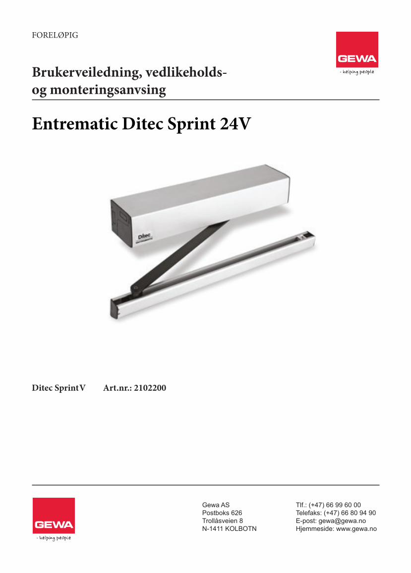
Entrematic Ditec Sprint 24V
Brukerveiledning, vedlikeholds-og monteringsanvsing
Foreløpig
Gewa ASPostboks 626Trollåsveien 8N-1411 KOLBOTN
Tlf.: (+47) 66 99 60 00Telefaks: (+47) 66 80 94 90E-post: [email protected]: www.gewa.no
Ditec Sprint V Art.nr.: 2102200
Ditec SprintSwing doors(Original instructions)
www.ditecentrematic.com
IP1546 ENTechnical Manual
2 IP15
46EN
- 2
013-
06-0
3
IndexSubject Page
1. General safety precautions 32. Declaration of incorporation of partly completed machinery 4
2.1 Machinery Directive 43. Technical details 5
3.1 Operating instructions 53.2 Dimensions 6
4. Standard installation 75. Main components 86. Mechanical installation 9
6.1 Removing the cover 97. Installation with SBS sliding arm 108. Installation with SBA articulated arm 119. Installation with SPRINTBRAS 3-lever articulated arm 1210. Installation of the floor doorstop 1311. Electrical connections 14
11.1 Electrical connections for 230 V - 120 V power supply 1411.2 Electrical connections for 24 V power supply 15
12. Connection of power supply 1513. Commands 1614. Outputs and accessories 16
14.1 Functions selector switch 1715. Electromagnetic emissions 1716. Adjustments 18
16.1 Trimmers enabling procedure 1816.2 Signals 18
17. Doors requirements for disabled 1918. Start-up 1919. Troubleshooting 2020. Routine maintenance plan 20
Operating instructions 21General safety precautions 21Manual release instructions 22
Caption
i This symbol indicates informations which are useful for correct product function.
This symbol indicates instructions or notes regarding safety issues which require particular attention.
3IP15
46EN
- 2
013-
06-0
3
1. General safety precautions
This installation manual is intended for qualified personnel only.Installation, electrical connections and adjustments must be performed in accordance with Good Working Methods and in com-pliance with applicable regulations.Before installing the product, carefully read the instructions. Bad installation could be hazardous.
The packaging materials (plastic, polystyrene, etc.) should not be discarded in the environment or left within reach of children, as these are a potential source of hazard.
Before installing the product, make sure it is in perfect condition.Do not install the product in an explosive environment and atmosphere: gas or inflammable fumes are a serious hazard risk.Before installing the motors, make all structural changes relating to safety clearances and protection or segregation of all areas where there is risk of being crushed, cut or dragged, and danger areas in general.Make sure the existing structure is up to standard in terms of strength and stability. The motor manufacturer is not responsible for failure to use Good Working Methods in building the frames to be motorized or for any deformation occurring during use.The safety devices (photocells, safety edges, emergency stops, etc.) must be installed taking into account: applicable laws and directives, Good Working Methods, installation premises, system operating logic and the forces developed by the motorized door.The safety devices must protect any areas where the risk exists of being crushed, cut or gragged, or where there are any other risks generated by the motorized door.Apply hazard area notices required by applicable regulations.Each installation must clearly show the identification details of the motorized door.
When necessary, connect the motorized door to a reliable earth system made in accordance with applicable safety regulations.During installation, maintenance and repair, interrupt the power supply before opening the lid to access the electrical parts.
The protective casing of the automation must be removed by qualified personnel only.To handle electronic parts, wear earthed antistatic conductive bracelets. The motor manufacturer declines all responsibility in the event of component parts being fitted that are not compatible with
the safe an correct operation.For repairs or replacements of products only original spare parts must be used. The installer shall provide all information relating to automatic, manual and emergency operation of the motorized door, and provide the user with operating instructions.
Failure to observe the information in this manual may result in minor personal injury or damage to equipment.
Save these instructions for future reference.
4 IP15
46EN
- 2
013-
06-0
3
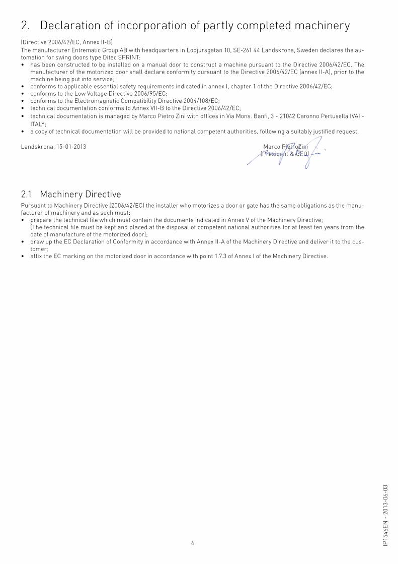
2. Declaration of incorporation of partly completed machinery
2.1 Machinery Directive
(Directive 2006/42/EC, Annex II-B)The manufacturer Entrematic Group AB with headquarters in Lodjursgatan 10, SE-261 44 Landskrona, Sweden declares the au-tomation for swing doors type Ditec SPRINT: • has been constructed to be installed on a manual door to construct a machine pursuant to the Directive 2006/42/EC. The
manufacturer of the motorized door shall declare conformity pursuant to the Directive 2006/42/EC (annex II-A), prior to the machine being put into service;
• conforms to applicable essential safety requirements indicated in annex I, chapter 1 of the Directive 2006/42/EC;• conforms to the Low Voltage Directive 2006/95/EC;• conforms to the Electromagnetic Compatibility Directive 2004/108/EC;• technical documentation conforms to Annex VII-B to the Directive 2006/42/EC;• technical documentation is managed by Marco Pietro Zini with offices in Via Mons. Banfi, 3 - 21042 Caronno Pertusella (VA) -
ITALY;• a copy of technical documentation will be provided to national competent authorities, following a suitably justified request.
Landskrona, 15-01-2013 Marco PietroZini (President & CEO)
Pursuant to Machinery Directive (2006/42/EC) the installer who motorizes a door or gate has the same obligations as the manu-facturer of machinery and as such must:• prepare the technical file which must contain the documents indicated in Annex V of the Machinery Directive; (The technical file must be kept and placed at the disposal of competent national authorities for at least ten years from the
date of manufacture of the motorized door);• draw up the EC Declaration of Conformity in accordance with Annex II-A of the Machinery Directive and deliver it to the cus-
tomer;• affix the EC marking on the motorized door in accordance with point 1.7.3 of Annex I of the Machinery Directive.
5IP15
46EN
- 2
013-
06-0
3
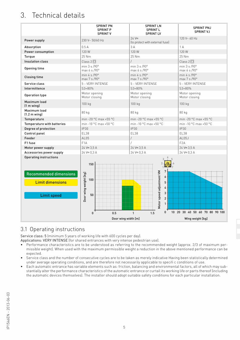
Control panel EL38F1 fuse F1AMotor power supply 24 V 3.5 A Accessories power supply 24 V 0.3 AService class: 5 (minimum 5 years of working life with 600 cycles per day).
Applications: VERY INTENSE (for shared entrances with very intense pedestrian use).• Performance characteristics are to be understood as referring to the recommended weight (approx. 2/3 of maximum per-
missible weight). When used with the maximum permissible weight a reduction in the above mentioned performance can be expected.
• Service class and the number of consecutive cycles are to be taken as merely indicative Having been statistically determined under average operating conditions, and are therefore not necessarily applicable to specifi c conditions of use.
• Each automatic entrance has variable elements such as: friction, balancing and environmental factors, all of which may sub-stantially alter the performance characteristics of the automatic entrance or curtail its working life or parts thereof (including the automatic devices themselves). The installer should adopt suitable safety conditions for each particular installation.
3. Technical details
3.1 Operating instructions
SPRINT PNSPRINT PSPRINT V
SPRINT LNSPRINT L
SPRINT LV
SPRINT PNJSPRINT VJ
Power supply 230 V~ 50/60 Hz 24 V (to protect with external fuse)
120 V~ 60 Hz
Absorption 0.5 A 3 A 1 APower consumption 120 W 120 W 120 WTorque 25 Nm 25 Nm 25 NmInsulation class Class 2 / Class 2
Opening time min 3 s /90°max 6 s /90°
min 3 s /90°max 6 s /90°
min 3 s /90°max 6 s /90°
Closing time min 4 s /90°max 7 s /90°
min 4 s /90°max 7 s /90°
min 4 s /90°max 7 s /90°
Service class 5 - VERY INTENSE 5 - VERY INTENSE 5 - VERY INTENSEIntermittence S3=80% S3=80% S3=80%
Operation type Motor openingMotor closing
Motor openingMotor closing
Motor openingMotor closing
Maximum load(1 m wing) 100 kg 100 kg 100 kg
Maximum load(1.2 m wing) 80 kg 80 kg 80 kg
Temperature min -20 °C max +55 °C min -20 °C max +55 °C min -20 °C max +55 °CTemperature with batteries min -10 °C max +50 °C min -10 °C max +50 °C min -10 °C max +50 °CDegree of protection IP30 IP30 IP30Control panel EL38 EL38 EL38Feeder AL05 / AL05JF1 fuse F1A / F2AMotor power supply 24 V 3,5 A 24 V 3,5 A 24 V 3,5 A Accessories power supply 24 V 0,3 A 24 V 0,3 A 24 V 0,3 AOperating instructions
Recommended dimensions
Limit dimensions
Limit speed
0
50
100
150
0.5
Door wing width [m]
Doo
r w
ing
wei
ght [
kg]
1 1.5
0
1
2
3
4
5
6
77
45
623
1
10 20 30 40 50 60 70 80 90 100
Wing weight [kg]
Mot
or s
peed
adj
ustm
ent V
M
6 IP15
46EN
- 2
013-
06-0
3
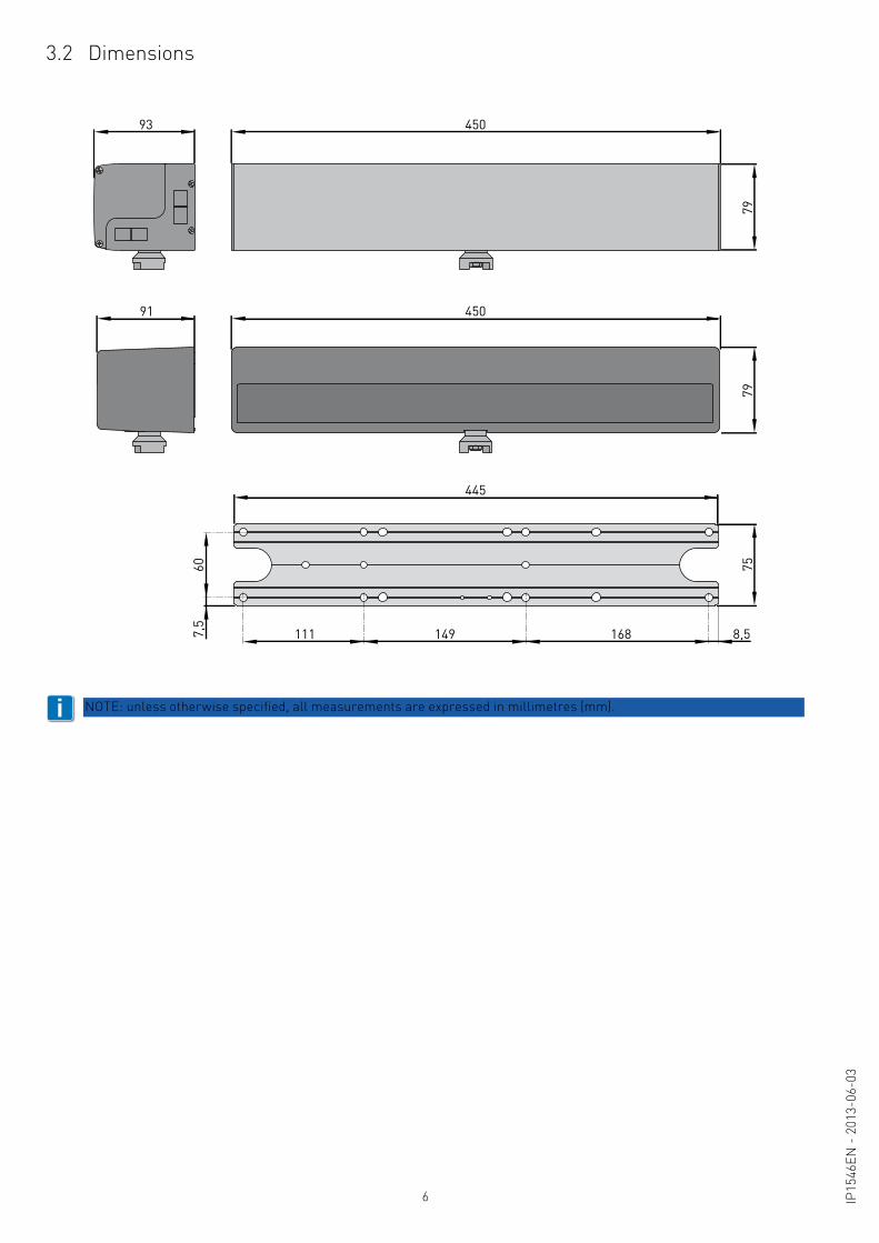
3.2 Dimensions
93 450
91 450
445
7979
75
7,5
60
8,5111 149 168
i NOTE: unless otherwise specified, all measurements are expressed in millimetres (mm).
7IP15
46EN
- 2
013-
06-0
3
4
6
6
15
7
2
3
A
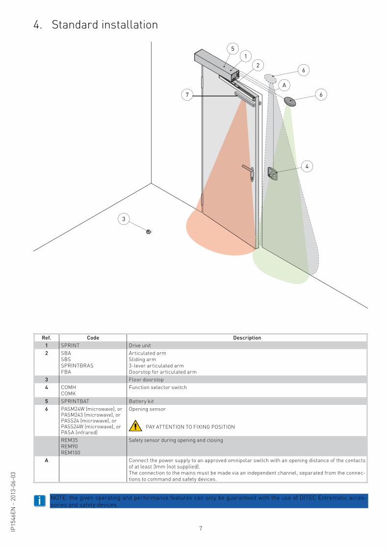
4. Standard installation
i NOTE: the given operating and performance features can only be guaranteed with the use of DITEC Entrematic acces-sories and safety devices.
Ref. Code Description1 SPRINT Drive unit2 SBA
SBSSPRINTBRASFBA
Articulated armSliding arm3-lever articulated armDoorstop for articulated arm
3 Floor doorstop4 COMH
COMKFunction selector switch
5 SPRINTBAT Battery kit6 PASM24W (microwave), or
PASM243 (microwave), orPASS24 (microwave), orPASS24W (microwave), orPASA (infrared)
Opening sensor
PAY ATTENTION TO FIXING POSITION
REM35REM90REM100
Safety sensor during opening and closing
A Connect the power supply to an approved omnipolar switch with an opening distance of the contacts of at least 3mm (not supplied).The connection to the mains must be made via an independent channel, separated from the connec-tions to command and safety devices.
8 IP15
46EN
- 2
013-
06-0
3
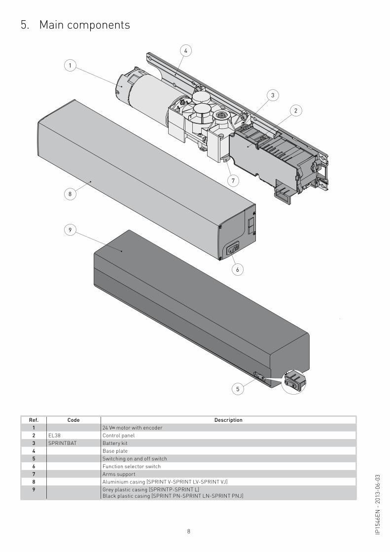
5. Main components
Ref. Code Description1 24 V motor with encoder2 EL38 Control panel3 SPRINTBAT Battery kit4 Base plate5 Switching on and off switch6 Function selector switch7 Arms support8 Aluminium casing [SPRINT V-SPRINT LV-SPRINT VJ]9 Grey plastic casing [SPRINTP-SPRINT L]
Black plastic casing [SPRINT PN-SPRINT LN-SPRINT PNJ]
1
9
2
3
5
7
8
4
6
9IP15
46EN
- 2
013-
06-0
3
Check the stability, the weight of the door wing and the regularity of the movement, without friction (if necessary reinforce the frame).Any “door check” must be eliminated or completely cancelled.
1
2
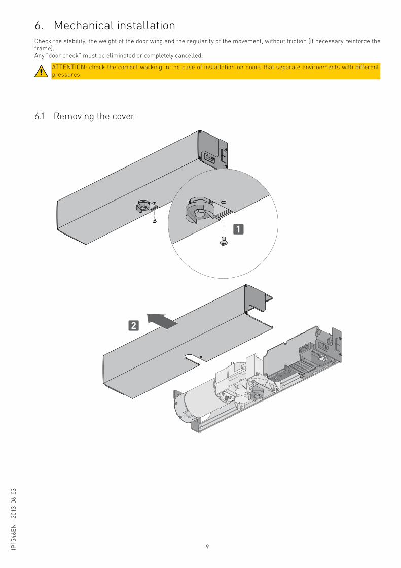
6. Mechanical installation
ATTENTION: check the correct working in the case of installation on doors that separate environments with different pressures.
6.1 Removing the cover
10 IP15
46EN
- 2
013-
06-0
3
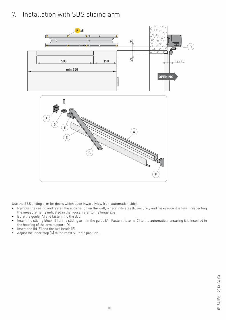
7. Installation with SBS sliding arm
Use the SBS sliding arm for doors which open inward (view from automation side).• Remove the casing and fasten the automation on the wall, where indicates (P) securely and make sure it is level, respecting
the measurements indicated in the figure: refer to the hinge axis.• Bore the guide [A] and fasten it to the door.• Insert the sliding block [B] of the sliding arm in the guide [A]. Fasten the arm [C] to the automation, ensuring it is inserted in
the housing of the arm support [D].• Insert the lid [E] and the two heads [F].• Adjust the inner stop [G] to the most suitable position.
500
min 650
150
3429
OPENING
max 45
x8
D
A
E
F
F
GB
C
DP
11IP15
46EN
- 2
013-
06-0
3
OPENING
46
44
320
max 300min 550
max
30
B
AA
C
90-100°
min 10°
C
x8DP
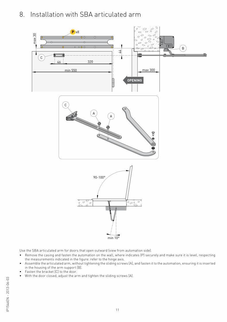
8. Installation with SBA articulated arm
Use the SBA articulated arm for doors that open outward (view from automation side).• Remove the casing and fasten the automation on the wall, where indicates (P) securely and make sure it is level, respecting
the measurements indicated in the figure: refer to the hinge axis.• Assemble the articulated arm, without tightening the sliding screws [A], and fasten it to the automation, ensuring it is inserted
in the housing of the arm support [B].• Fasten the bracket [C] to the door.• With the door closed, adjust the arm and tighten the sliding screws [A].
12 IP15
46EN
- 2
013-
06-0
3
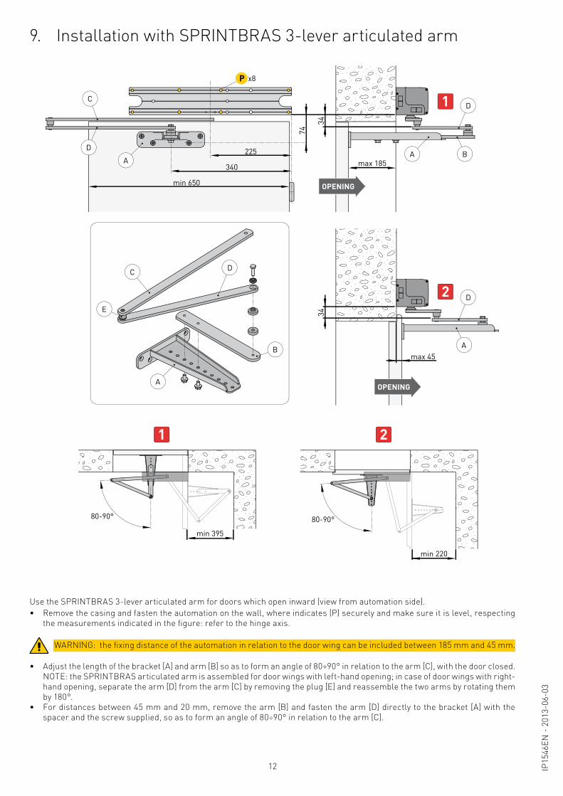
9. Installation with SPRINTBRAS 3-lever articulated arm
• Adjust the length of the bracket [A] and arm [B] so as to form an angle of 80÷90° in relation to the arm [C], with the door closed. NOTE: the SPRINTBRAS articulated arm is assembled for door wings with left-hand opening; in case of door wings with right-
hand opening, separate the arm [D] from the arm [C] by removing the plug [E] and reassemble the two arms by rotating them by 180°.
• For distances between 45 mm and 20 mm, remove the arm [B] and fasten the arm [D] directly to the bracket [A] with the spacer and the screw supplied, so as to form an angle of 80÷90° in relation to the arm [C].
Use the SPRINTBRAS 3-lever articulated arm for doors which open inward (view from automation side).• Remove the casing and fasten the automation on the wall, where indicates (P) securely and make sure it is level, respecting
the measurements indicated in the figure: refer to the hinge axis.
max 185
34
min 650
340
225
34
74
OPENING
OPENING
max 45
1
min 395
min 220
80-90°
2
2
C
D
A
B
80-90°
A
DA B
A
D
D
1
E
C
x8DP
WARNING: the fixing distance of the automation in relation to the door wing can be included between 185 mm and 45 mm.
13IP15
46EN
- 2
013-
06-0
3
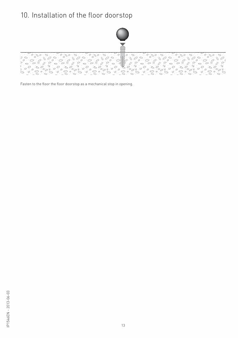
Fasten to the floor the floor doorstop as a mechanical stop in opening.
10. Installation of the floor doorstop
14 IP15
46EN
- 2
013-
06-0
3
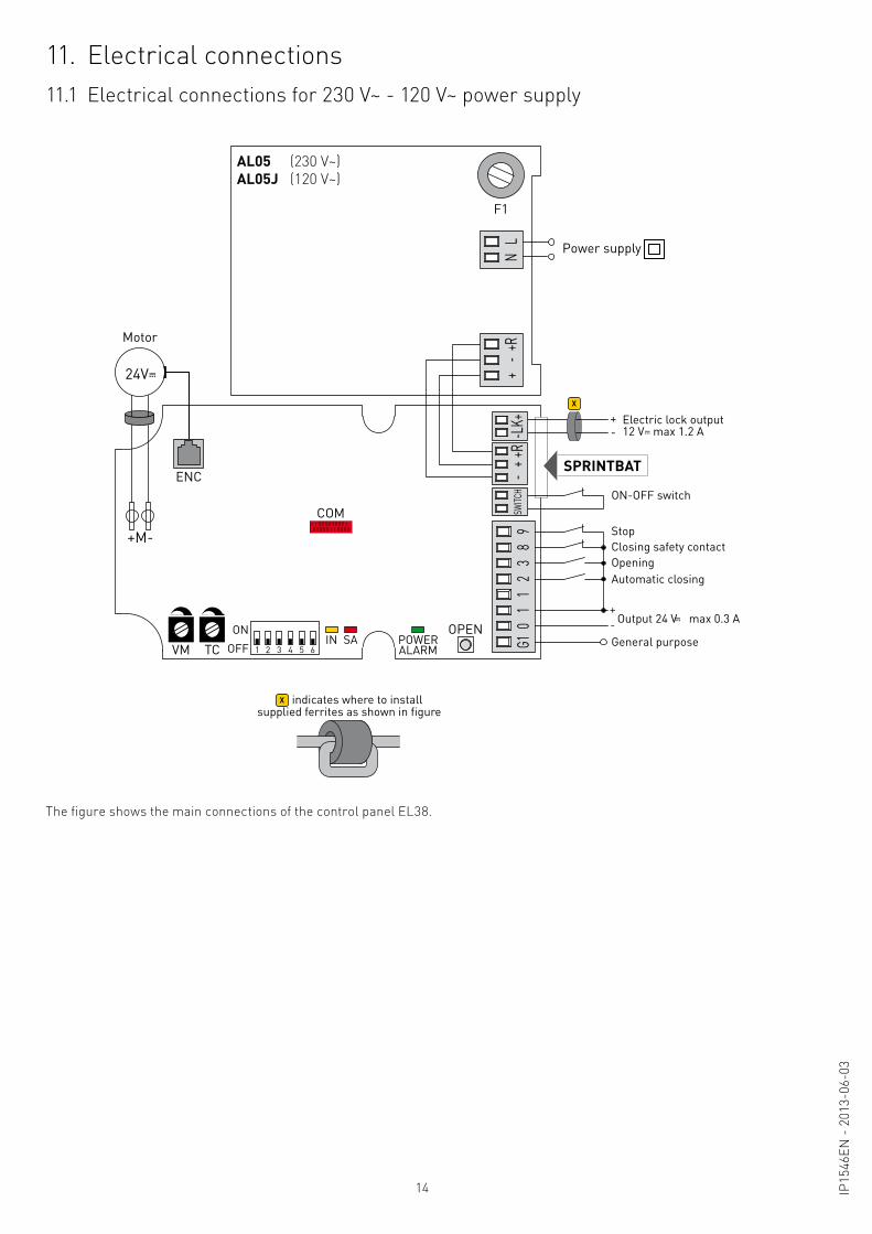
11. Electrical connections11.1 Electrical connections for 230 V~ - 120 V~ power supply
The figure shows the main connections of the control panel EL38.
ONOFF 1 2 3 4 5 6VM TC
OPEN
COM
ENC
G10
11
23
89
+-
+R+
-+R
SWITC
H
SA POWERALARM
IN
+M--L
K+
F1
NL
Motor
24V
Power supply
+-
OpeningClosing safety contact
ON-OFF switch
Stop
Automatic closing
General purpose
SPRINTBAT
AL05 (230 V~)AL05J (120 V~)
X
Output 24 V max 0.3 A
Electric lock output12 V max 1.2 A
+-
supplied ferrites as shown in figureindicates where to installX
15IP15
46EN
- 2
013-
06-0
3
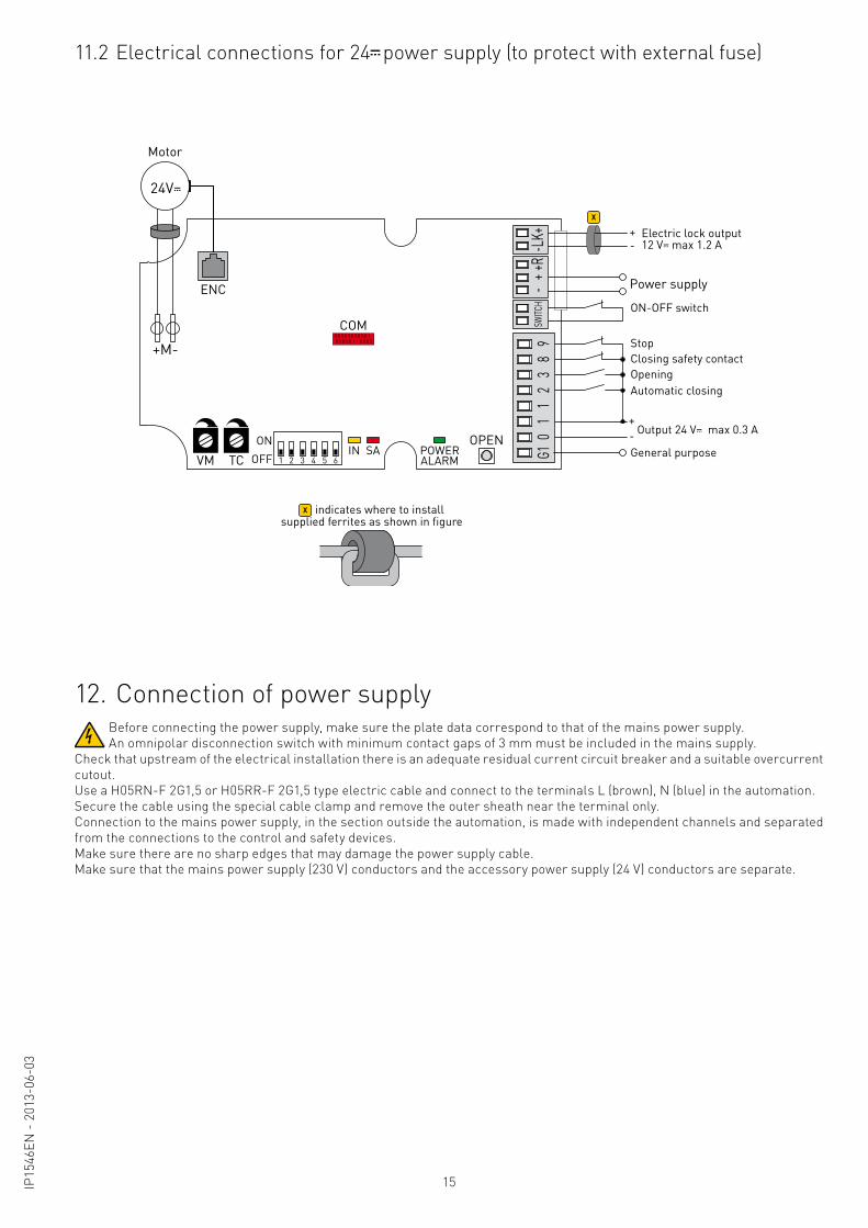
11.2 Electrical connections for 24 power supply (to protect with external fuse)
Before connecting the power supply, make sure the plate data correspond to that of the mains power supply.An omnipolar disconnection switch with minimum contact gaps of 3 mm must be included in the mains supply.
Check that upstream of the electrical installation there is an adequate residual current circuit breaker and a suitable overcurrent cutout.Use a H05RN-F 2G1,5 or H05RR-F 2G1,5 type electric cable and connect to the terminals L (brown), N (blue) in the automation.Secure the cable using the special cable clamp and remove the outer sheath near the terminal only.Connection to the mains power supply, in the section outside the automation, is made with independent channels and separated from the connections to the control and safety devices.Make sure there are no sharp edges that may damage the power supply cable.Make sure that the mains power supply (230 V) conductors and the accessory power supply (24 V) conductors are separate.
12. Connection of power supply
ONOFF 1 2 3 4 5 6VM TC
OPEN
COM
ENC
G10
11
23
89
+-
+RSW
ITCH
SA POWERALARM
IN
+M-
-LK+
Motor
24V
Power supply
+-
OpeningClosing safety contact
ON-OFF switch
Stop
Automatic closing
General purpose
X
Output 24 V max 0.3 A
Electric lock output12 V max 1.2 A
+-
supplied ferrites as shown in figureindicates where to installX
16 IP15
46EN
- 2
013-
06-0
3
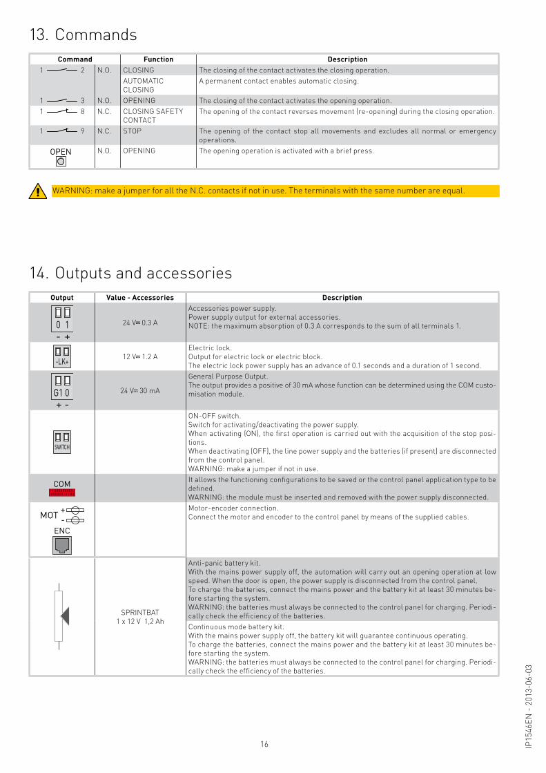
13. Commands
WARNING: make a jumper for all the N.C. contacts if not in use. The terminals with the same number are equal.
Command Function Description1 2 N.O. CLOSING The closing of the contact activates the closing operation.
AUTOMATIC CLOSING
A permanent contact enables automatic closing.
1 3 N.O. OPENING The closing of the contact activates the opening operation.1 8 N.C. CLOSING SAFETY
CONTACTThe opening of the contact reverses movement (re-opening) during the closing operation.
1 9 N.C. STOP The opening of the contact stop all movements and excludes all normal or emergency operations.
OPEN N.O. OPENING The opening operation is activated with a brief press.
14. Outputs and accessoriesOutput Value - Accessories Description
4 90 1 2 3+-
24 V 0.3 A
Accessories power supply. Power supply output for external accessories.NOTE: the maximum absorption of 0.3 A corresponds to the sum of all terminals 1.
-LK+ 12 V 1.2 AElectric lock.Output for electric lock or electric block.The electric lock power supply has an advance of 0.1 seconds and a duration of 1 second.
4 9G1 0 2 3-+
24 V 30 mA
General Purpose Output.The output provides a positive of 30 mA whose function can be determined using the COM custo-misation module.
SWITCH
ON-OFF switch. Switch for activating/deactivating the power supply.When activating (ON), the first operation is carried out with the acquisition of the stop posi-tions.When deactivating (OFF), the line power supply and the batteries (if present) are disconnected from the control panel.WARNING: make a jumper if not in use.
COM It allows the functioning configurations to be saved or the control panel application type to be defined.WARNING: the module must be inserted and removed with the power supply disconnected.
MOT +-
ENC
Motor-encoder connection.Connect the motor and encoder to the control panel by means of the supplied cables.
SPRINTBAT1 x 12 V 1,2 Ah
Anti-panic battery kit.With the mains power supply off, the automation will carry out an opening operation at low speed. When the door is open, the power supply is disconnected from the control panel.To charge the batteries, connect the mains power and the battery kit at least 30 minutes be-fore starting the system.WARNING: the batteries must always be connected to the control panel for charging. Periodi-cally check the efficiency of the batteries.Continuous mode battery kit.With the mains power supply off, the battery kit will guarantee continuous operating.To charge the batteries, connect the mains power and the battery kit at least 30 minutes be-fore starting the system.WARNING: the batteries must always be connected to the control panel for charging. Periodi-cally check the efficiency of the batteries.
17IP15
46EN
- 2
013-
06-0
3
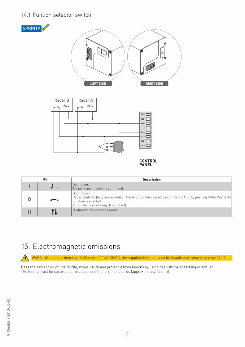
Radar A24 V+ -
Radar B24 V+ -
LEFT SIDE RIGHT SIDE
CONTROLPANEL
SPRINTV
G10
11
23
89
14.1 Funtion selector switch
Rif. DescriptionDoor open.1-3 permanent opening command.Door closed.Radar controls (A-3) are excluded. The door can be opened by control 1-3A or by pushing if the Push&Go function is enabled.Automatic door closing (1-2 contact).Bi-directional operating mode.
Pass the cable through the ferrite, make 1 turn and protect it from knocks by using heat-shrink sheathing or similar.The ferrite must be secured to the cable near the terminal boards (approximately 50 mm).
15. Electromagnetic emissionsWARNING: in accordance with Directive 2004/108/EC, the supplied ferrites must be installed as shown on page 14-15.
18 IP15
46EN
- 2
013-
06-0
3
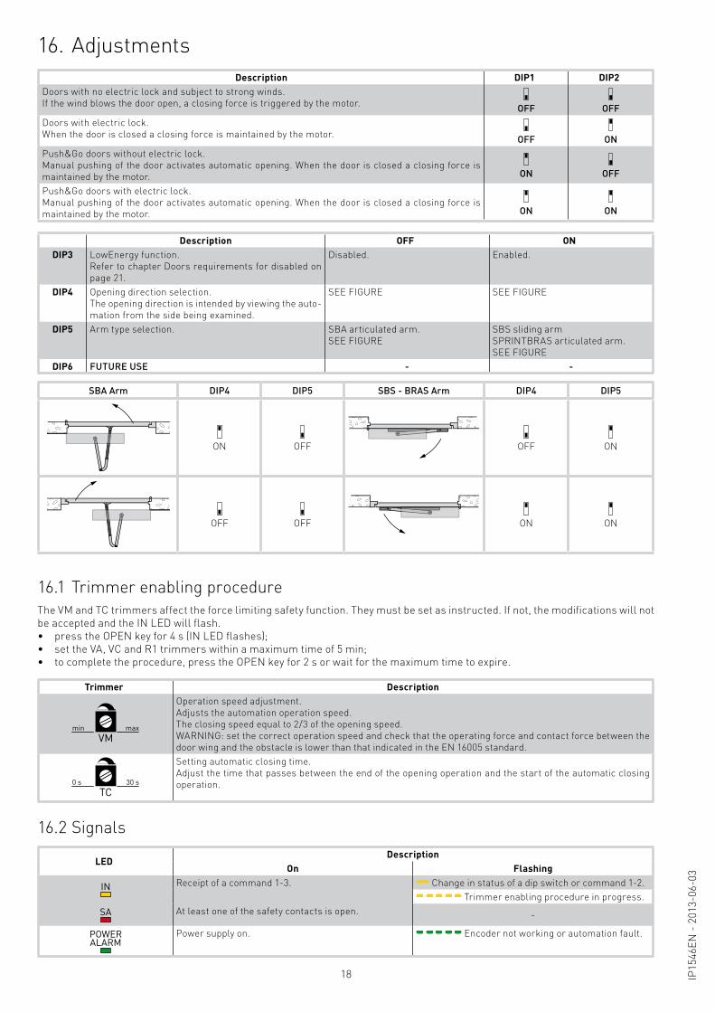
16. AdjustmentsDescription DIP1 DIP2
Doors with no electric lock and subject to strong winds. If the wind blows the door open, a closing force is triggered by the motor. OFF OFFDoors with electric lock.When the door is closed a closing force is maintained by the motor. OFF ONPush&Go doors without electric lock.Manual pushing of the door activates automatic opening. When the door is closed a closing force is maintained by the motor. ON OFF
Push&Go doors with electric lock.Manual pushing of the door activates automatic opening. When the door is closed a closing force is maintained by the motor. ON ON
Description OFF ONDIP3 LowEnergy function.
Refer to chapter Doors requirements for disabled on page 21.
Disabled. Enabled.
DIP4 Opening direction selection.The opening direction is intended by viewing the auto-mation from the side being examined.
SEE FIGURE SEE FIGURE
DIP5 Arm type selection. SBA articulated arm.SEE FIGURE
SBS sliding arm SPRINTBRAS articulated arm.SEE FIGURE
DIP6 FUTURE USE - -
The VM and TC trimmers affect the force limiting safety function. They must be set as instructed. If not, the modifications will not be accepted and the IN LED will flash.• press the OPEN key for 4 s (IN LED flashes);• set the VA, VC and R1 trimmers within a maximum time of 5 min;• to complete the procedure, press the OPEN key for 2 s or wait for the maximum time to expire.
16.1 Trimmer enabling procedure
16.2 Signals
Trimmer Description
min maxVM
Operation speed adjustment.Adjusts the automation operation speed.The closing speed equal to 2/3 of the opening speed.WARNING: set the correct operation speed and check that the operating force and contact force between the door wing and the obstacle is lower than that indicated in the EN 16005 standard.
0 s 30 sTC
Setting automatic closing time.Adjust the time that passes between the end of the opening operation and the start of the automatic closing operation.
LEDDescription
On Flashing
IN Receipt of a command 1-3. Change in status of a dip switch or command 1-2. Trimmer enabling procedure in progress.
SA At least one of the safety contacts is open. -
POWERALARM
Power supply on. Encoder not working or automation fault.
SBA Arm DIP4 DIP5 SBS - BRAS Arm DIP4 DIP5
ON OFF OFF ON
OFF OFF ON ON
19IP15
46EN
- 2
013-
06-0
3
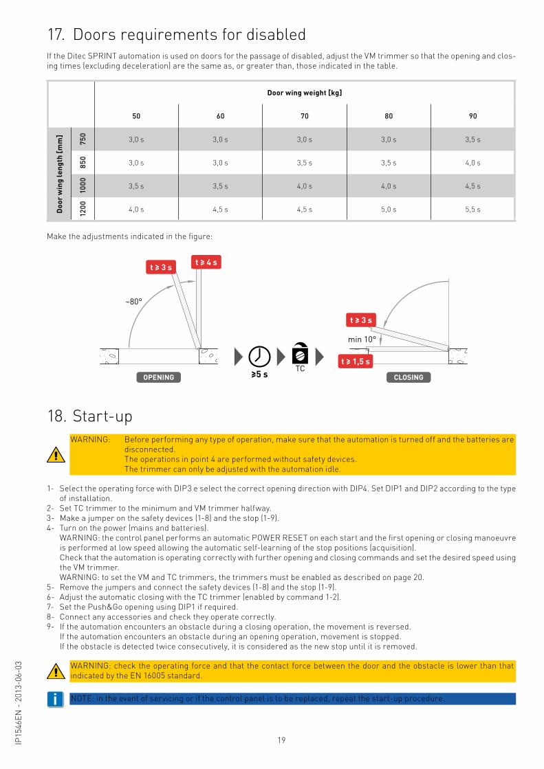
Door wing weight [kg]
50 60 70 80 90
Doo
r w
ing
leng
th [m
m]
750
3,0 s 3,0 s 3,0 s 3,0 s 3,5 s
850
3,0 s 3,0 s 3,5 s 3,5 s 4,0 s
1000 3,5 s 3,5 s 4,0 s 4,0 s 4,5 s
1200 4,0 s 4,5 s 4,5 s 5,0 s 5,5 s
If the Ditec SPRINT automation is used on doors for the passage of disabled, adjust the VM trimmer so that the opening and clos-ing times (excluding deceleration) are the same as, or greater than, those indicated in the table.
Make the adjustments indicated in the figure:
≥5 s
~80°
min 10°
OPENING
t ≥ 3 s t ≥ 4 s
CLOSING
t ≥ 3 s
t ≥ 1,5 sTC
17. Doors requirements for disabled
1- Select the operating force with DIP3 e select the correct opening direction with DIP4. Set DIP1 and DIP2 according to the type of installation.
2- Set TC trimmer to the minimum and VM trimmer halfway.3- Make a jumper on the safety devices (1-8) and the stop (1-9).4- Turn on the power (mains and batteries). WARNING: the control panel performs an automatic POWER RESET on each start and the first opening or closing manoeuvre
is performed at low speed allowing the automatic self-learning of the stop positions (acquisition). Check that the automation is operating correctly with further opening and closing commands and set the desired speed using
the VM trimmer. WARNING: to set the VM and TC trimmers, the trimmers must be enabled as described on page 20.5- Remove the jumpers and connect the safety devices (1-8) and the stop (1-9).6- Adjust the automatic closing with the TC trimmer (enabled by command 1-2).7- Set the Push&Go opening using DIP1 if required.8- Connect any accessories and check they operate correctly.9- If the automation encounters an obstacle during a closing operation, the movement is reversed. If the automation encounters an obstacle during an opening operation, movement is stopped. If the obstacle is detected twice consecutively, it is considered as the new stop until it is removed.
18. Start-upWARNING: Before performing any type of operation, make sure that the automation is turned off and the batteries are
disconnected. The operations in point 4 are performed without safety devices. The trimmer can only be adjusted with the automation idle.
WARNING: check the operating force and that the contact force between the door and the obstacle is lower than that indicated by the EN 16005 standard.
i NOTE: in the event of servicing or if the control panel is to be replaced, repeat the start-up procedure.
20 IP15
46EN
- 2
013-
06-0
3
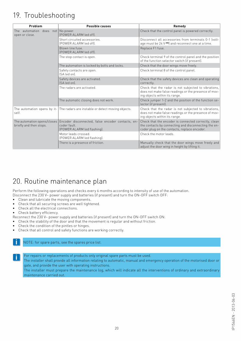
19. TroubleshootingProblem Possible causes Remedy
The automation does not open or close.
No power.(POWER ALARM led off).
Check that the control panel is powered correctly.
Short circuited accessories.(POWER ALARM led off).
Disconnect all accessories from terminals 0-1 (volt-age must be 24 V ) and reconnect one at a time.
Blown line fuse.(POWER ALARM led off).
Replace F1 fuse.
The stop contact is open. Check terminal 9 of the control panel and the position of the function selector switch (if present).
The automation is locked by bolts and locks. Check that the door wings move freely.Safety contacts are open.(SA led on).
Check terminal 8 of the control panel.
Safety devices are activated.(SA led on).
Check that the safety devices are clean and operating correctly.
The radars are activated. Check that the radar is not subjected to vibrations, does not make false readings or the presence of mov-ing objects within its range.
The automatic closing does not work. Check jumper 1-2 and the position of the function se-lector (if present).
The automation opens by it-self.
The radars are instable or detect moving objects. Check that the radar is not subjected to vibrations, does not make false readings or the presence of mov-ing objects within its range.
The automation opens/closes briefly and then stops.
Encoder disconnected, false encoder contacts, en-coder fault.(POWER ALARM led flashing).
Check that the encoder is connected correctly, clean the contacts by connecting and disconnecting the en-coder plug on the contacts, replace encoder.
Motor leads crossed.(POWER ALARM led flashing).
Check the motor leads.
There is a presence of friction. Manually check that the door wings move freely and adjust the door wing in height by lifting it.
Perform the following operations and checks every 6 months according to intensity of use of the automation.Disconnect the 230 V~ power supply and batteries (if present) and turn the ON-OFF switch OFF: • Clean and lubricate the moving components.• Check that all securing screws are well tightened.• Check all the electrical connections.• Check battery efficiency.Reconnect the 230 V~ power supply and batteries (if present) and turn the ON-OFF switch ON:• Check the stability of the door and that the movement is regular and without friction.• Check the condition of the pintles or hinges.• Check that all control and safety functions are working correctly.
20. Routine maintenance plan
i
i
NOTE: for spare parts, see the spares price list.
For repairs or replacements of products only original spare parts must be used.The installer shall provide all information relating to automatic, manual and emergency operation of the motorised door or gate, and provide the user with operating instructions.The installer must prepare the maintenance log, which will indicate all the interventions of ordinary and extraordinary maintenance carried out.
21IP15
46EN
- 2
013-
06-0
3
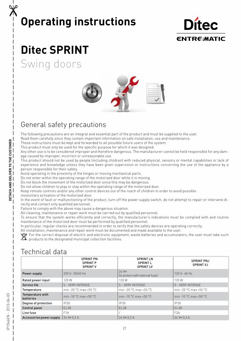
General safety precautions
Ditec SPRINTSwing doors
Operating instructionsD
ETAC
H A
ND
DEL
IVER
TO
TH
E CU
STO
MER
The following precautions are an integral and essential part of the product and must be supplied to the user.Read them carefully since they contain important information on safe installation, use and maintenance.These instructions must be kept and forwarded to all possible future users of the system.This product must only be used for the specific purpose for which it was designed.Any other use is to be considered improper and therefore dangerous. The manufacturer cannot be held responsible for any dam-age caused by improper, incorrect or unreasonable use.This product should not be used by people (including children) with reduced physical, sensory or mental capabilities or lack of experience and knowledge unless they have been given supervision or instructions concerning the use of the appliance by a person responsible for their safety.Avoid operating in the proximity of the hinges or moving mechanical parts.Do not enter within the operating range of the motorized door while it is moving.Do not block the movement of the motorized door since this may be dangerous.Do not allow children to play or stay within the operating range of the motorized door.Keep remote controls and/or any other control devices out of the reach of children in order to avoid possibleinvoluntary activation of the motorized door.In the event of fault or malfunctioning of the product, turn off the power supply switch, do not attempt to repair or intervene di-rectly and contact only qualified personnel.Failure to comply with the above may cause a dangerous situation.All cleaning, maintenance or repair work must be carried out by qualified personnel.To ensure that the system works efficiently and correctly, the manufacturer’s indications must be complied with and routine maintenance of the motorized door must be performed by qualified personnel.In particular, regular checks are recommended in order to verify that the safety devices are operating correctly.All installation, maintenance and repair work must be documented and made available to the user.
For the correct disposal of electric and electronic equipment, waste batteries and accumulators, the user must take such products to the designated municipal collection facilities.
Technical dataSPRINT PNSPRINT PSPRINT V
SPRINT LNSPRINT L
SPRINT LV
SPRINT PNJSPRINT VJ
Power supply 230 V~ 50/60 Hz 24 V (to protect with external fuse) 120 V~ 60 Hz
Rated power input 120 W 120 W 120 WService life 5 - VERY INTENSE 5 - VERY INTENSE 5 - VERY INTENSETemperature min -20 °C max +55 °C min -20 °C max +55 °C min -20 °C max +55 °CTemperature with batteries min -10 °C max +50 °C min -10 °C max +50 °C min -10 °C max +50 °C
Degree of protection IP30 IP30 IP30 Control panel EL38 EL38 EL38Line fuse F1A / F2AAccessories power supply 24 V 0,3 A 24 V 0,3 A 24 V 0,3 A
22 IP15
46EN
- 2
013-
06-0
3
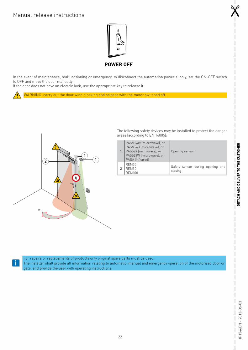
In the event of maintenance, malfunctioning or emergency, to disconnect the automation power supply, set the ON-OFF switch to OFF and move the door manually.If the door does not have an electric lock, use the appropriate key to release it.
POWER OFF
Manual release instructions
DET
ACH
AN
D D
ELIV
ER T
O T
HE
CUST
OM
ER
WARNING: carry out the door wing blocking and release with the motor switched off.
The following safety devices may be installed to protect the danger areas (according to EN 16005):
1
PASM24W (microwave), orPASM243 (microwave), orPASS24 (microwave), orPASS24W (microwave), orPASA (infrared)
Opening sensor
2REM35REM90REM100
Safety sensor during opening and closing
11
2
iFor repairs or replacements of products only original spare parts must be used.The installer shall provide all information relating to automatic, manual and emergency operation of the motorised door or gate, and provide the user with operating instructions.

23IP15
46EN
- 2
013-
06-0
3
All rights related to this material are the exclusive property of Entrematic Group AB.Although the contents of this publication have been compiled with the greatest possible care, Entrematic Group AB cannot accept liability for any damage that might arise from errors or omissions in this publication. We reserve the right to make modifications without prior notice. No part of this publication may be copied, scanned, adapted or modified without prior permission in writing from Entrematic Group AB.

Entrematic Italy S.p.A. Via V. Pisani, 20 20124 Milano (MI) ITALIA Tel. +39 02 963911 Fax +39 02 9650314www.ditecentrematic.com
IP15
46EN
- 2
013-
06-0
3