entity-based system dynamics abstract -...
TRANSCRIPT

VENTANA systems, inc. 1
Entity-Based System Dynamics
Larry Yeager, [email protected]
Thomas Fiddaman, [email protected] David Peterson. [email protected]
Ventana Systems, Inc. 60 Jacob Gates Road
Harvard, MA 01451
Abstract
We describe a new platform for system dynamics modeling that supports detailed and object
oriented modeling while preserving attractive features of existing tools, including a completely declarative language with a graphical representation. New concepts supporting this platform
include collections of entities, attributes, relationships, aggregation and allocation functions, and actions, which are presented with examples. The design facilitates modularity and collaboration,
provides a more natural description of detail than arrays, and solves sparse matrix problems. It
has application to both traditional system dynamics, with modular sectors, and to agent based modeling.
3/19/2014

VENTANA systems, inc. 2
Introduction
The authors believe that the emerging needs for modeling large and complex systems can best be addressed through a new modeling language and platform that is based on system dynamics
but that is designed from the ground up to support object oriented modeling. This paper provides an overview of such a platform. Before we proceed, we discuss some of the strengths
and weaknesses of existing approaches.
Strengths of Traditional SD Tools
System dynamics modeling and the tools that support it offer unique advantages for building
simulation models of large and complex systems. These include,
Use of graphical descriptions, with a limited number of core abstractions, to promote
inspection and peer interaction.
Useful variable names and documentation fields.
Declarative languages with automatic renaming.
Separation of model structure from data and output (unlike spreadsheets).
Productive debugging from visibility of full model state and Causal Tracing™.
Good testing habits and automated testing tools, as in Vensim’s Reality Check™.
Easy syntax and unit checking.
The Challenges Presented by Complex Systems
In Business Dynamics, Sterman (2000, Chapter 22) discusses “Challenges for the Future”. He calls for improving group modeling, speeding the process, and integrating modeling
methodologies. He also cites the importance of linking models with each other and with
potentially large databases. Modelers have increasingly bumped up against the limits of traditional system dynamics in a number of areas:
Communication of results with beauty and clarity that can compete with other media.
Management of detail, including,
o Situations in which the combinatorics of overlapping states make it difficult to
draw sensible stock-flow diagrams a priori.
o Multi-tier relationships that make array syntax arcane and difficult, even for
experienced modelers.
o Systems that cannot be accurately aggregated, as in agent based models where
behavior emerges from granularity at the individual level rather than the
population level.
o Sparse matrices that are better represented by lists than by multidimensional
arrays.
o Dynamic activation of structure, or creation and deletion of agents.
Team model building and reuse of structure across projects, requiring modularity and
support for source control.
End-to-end management of large scale data.

VENTANA systems, inc. 3
Advanced algorithms requiring parallel or grid computing.
When tools fail to support these areas, opportunities are missed to reduce costs and increase the quality of system dynamics work.
Limitations of Current System Dynamics Tools
Ordinary applications of system dynamics tools suffer from some more mundane limitations as well.
Variable names are typically global and must be unique within the model. This means that the variable name must include both the context and the item identification. For instance, in a
business model, there may be many separate “Cash” variables. With an object-oriented
approach, variable names are only unique within an entity type. References to variables defined in separate objects include the reference name, which increases clarity and simplifies the
application of modular design principles.
Replication of structure generally involves either copy/paste/edit, macros or arrays. Copy/paste is
a manual process and therefore not very flexible. Macros are rather opaque to the user. Arrays
are a property defined for individual variables, though conceptually dimensions are generally a property of a subsystem. Arrays become arduous to use when they must be mapped across
subsystems with differing levels of detail. Arrays become especially awkward if they are used to model items that are dynamically created and deleted; the result is large static arrays, very
complex equations, and slow simulations
Solutions
Most of these challenges can be met already through the use of flexible tools based on object
oriented programming. However, in many cases this foregoes much of the clarity and efficiency of SD tools. It also increases cost and shrinks the pool of skilled practitioners, who must
simultaneously be modelers and programmers.
Modularity
Productivity of modelers could be improved by increasing the ability to reuse tested components
within a model or across projects. Team modeling is challenged by the difficult task of connecting model components, especially when components are being developed by separate
individuals or teams.
The software industry has addressed the cost and reusability issue effectively with the
emergence of object oriented programming and design. In this paper, we propose that these principles be applied to the building of system dynamics models and discuss a platform that
implements these proposals.
The desire to reuse model components is not new. Eberlein and Hines (1996) proposed the use of standardized molecules that could speed up implementation. Tignor (1999), Tignor and
Myrtveit (2000), and Myrtveit (2000) proposed a variety of object oriented extensions to system dynamics implementations. Logical grouping and hierarchical model building is also important, as
presented by Eubanks and Yeager (2001). Bauer and Bodendorf (2006) created a Model
Composer that would assemble a composite model using components built with Vensim. According to Osgood and Tian (2012), modularity is one of the key principles in software
engineering. They go on to say that “most System Dynamics modules remain stubbornly monolithic”.

VENTANA systems, inc. 4
Agent Detail
Numerous efforts to combine system dynamics and agent based modeling have been attempted due to the unique capabilities offered by each paradigm. With significant effort, some agent-like
models have been constructed using system dynamics tools. Sterman (2000, p. 896) states that “There are different simulation methods for agent-based modeling, ranging from simple cellular
automata to detailed, disaggregate system dynamics models.” He identified agent-based
modeling as one of the key areas for advancing the theory of dynamic simulation. Schieritz and Grobler (2003) describe a hybrid model that uses agent-style control structure to instantiate and
manage small system dynamics models running in Vensim.
Agent-based modeling provides several capabilities that are not available in traditional system
dynamics models. Gilbert and Terna (2000) emphasize the similarities between an “object” and an “agent”. Schieritz (2002) describes integrating system dynamics and agent modeling. She
notes that “The drawback of the system dynamics approach in modeling supply networks is the
fixed structure of a system dynamics model”. Schieritz and Milling (2003) provide a lengthy comparison of system dynamics and agent-based modeling. The source of dynamics is identified
as levels (system dynamics) versus events (agent-based modeling). Although aggregate levels provide an adequate representation of many systems, it is clear that the effective study of many
complex social systems requires the ability to dynamically create and delete agents (or objects or
entities).
Behdani (2012) compares system dynamics, discrete event modeling, and agent-based modeling.
Behdani identifies eight capabilities that appear to favor an agent-based approach. The first four items are the ability to create numerous heterogeneous items, the potential for local interaction,
nestedness (relationships to sub-components), and adaptiveness. Although all of these can and have been modeled using system dynamics languages, some of these models require contortions
by the modeling team. Emergence, self-organization, and co-evolution are heavily dependent on
the ability of the system dynamics modelers to stretch array-based software far beyond its normal range of clarity and efficiency.
Thus, it appears that the major issues required to integrate agent-type behavior into a system dynamics model are the ability to define agents in system dynamics diagrams and to then create
and delete these agents and to dynamically configure their relationships with other agents and
the environment.
The final point noted by Behdani is “Path Dependency”. In this context, that means the ability to
use the agent’s history and prior observations as input to decisions and actions. This capability is fully supported by the platform described in this article.
Lessons from Software Development
Osgood and Tian (2012) make many recommendations in their paper “15 Things System Dynamics can Learn from Software Development”. The object-oriented paradigm in software
development significantly improved the generation and application of reusable modules. Object-oriented design will also support “Encapsulation and Abstractions by Specification”, “Interface-
Based Development”, and “Mocking”. These software engineering features establish module specifications, separation of those specifications into formal interfaces, and create test modules
that satisfy the interface and can be used in place of the full module for improved testing or
development.

VENTANA systems, inc. 5
Entity Based System Dynamics
The approach we now describe includes several important extensions to the system dynamics toolset:
- Entity type definitions, providing objects or modules
- Attributes used to identify and categorize individual entities
- Collections of entities automatically generated and tracked by attribute
- Aggregation and allocation functions that make one-to-many or many-to-many
mappings among collections and individual entities
- References, or special attributes used to connect entities of the same or different types
- Actions, providing for discrete events like the dynamic creation and deletion of entities
While these concepts are not part of the familiar lexicon, we expect that they will make modeling
detail more natural, whether for representing sectors in a traditional flat system dynamics models or for agent based modeling. Collections of entities are more natural than arrays, because detail
is a property of an institution, vehicle, or person, rather than a property of each and every equation that describes that entity. For the advanced modeler, these constructs greatly amplify
what is possible; for the beginning modeler, none of these constructs need be addressed until required.
The organization of models into component types that correspond to actual structures and
organizations should help make modeling clients and stakeholders more confident in the associated models because the diagrams can correspond directly to familiar concepts. It is
furthermore expected that subject matter experts would be able to construct, review, and validate portions of models without needing to deal with the entire system.
The platform design includes a non-procedural language for defining all model components, a
graphical representation of all model components, and the ability to support object oriented system dynamics as well as discrete events and agent-based models.
Modular Definition Structure
Building a model of a complex system can be most easily accomplished by building smaller
models of each type of component that is part of that system. We refer to these components as entity type definitions. Entities may represent a wide range of components such as physical
entities, organizations, facilities, products, logical collections, and abstractions. Typical
combinations could include:
- City/Region: city departments, neighborhoods, power plants, populations, businesses,
health care providers, agencies, business, schools
- Company Strategy: product lines, markets, consumers, competitors, departments
Portfolio Planning: projects, tasks, resource groups, pre-requisites, quality and
productivity relationships
Entity Type Definition
The modeler creates, or reuses from prior work, a separate model definition for each type of component in the system. For example, the modeler may define a “customer” type. These
entity type definitions are constructed using graphical definition capabilities that support

VENTANA systems, inc. 6
traditional stock and flow diagrams. Equations are defined in the familiar non-procedural
structure like that supported by current system dynamics software. Entity type definitions also contain identifiers that can be used to uniquely identify each entity.
Entity type definitions are stored in separate files. Thus, it is much easier to manage model development by distributed teams. Alternative entity type definitions may be substituted for each
other to generate scenarios or to test alternative versions of the model. Interface specifications
list the required input variables and identify the output variables that must be supplied to outside entities.
At the start of model execution, entities may be specified by external data sources, making it easier to use a model or its components across many separate simulation applications. For
instance, a customer entity type might be used in many different applications, each time being invoked to create a different number of customers with different properties. The structure of
entity type definitions makes it easy to load extremely large data sets from databases or from
files.
These entity type definitions are intentionally similar to class definitions in an object oriented
programming language. This approach supports the key benefits of object oriented design that relate to dynamic simulation – without requiring programming expertise. These key benefits
include the ability to create and delete entities during a simulation, the ability to override
equations (methods), and the ability to base an entity type definition on another entity type definition (inheritance and multiple inheritance). By defining empty interfaces for entity types,
teams of users can specify high level interactions among model components that will later be completed in parallel.
Each entity type definition can be defined using system dynamics stock and flow diagrams. Figure 1 shows an entity type definition with a diagram and a list of all of its variables.

VENTANA systems, inc. 7
Figure 1
By referencing this definition, the model can create, delete, merge, or split entities during model
execution.
Attributes
Each entity contains one or more identifiers, called attributes, which are used to access each
entity of a given type. Attributes serve a similar role to key fields in relational database tables.
Attributes are non-numeric variables that are used to identify, categorize, and logically
differentiate entities created from the same entity type definition. Attribute values are visible to the model user as names and text strings. Attributes support the modeling of references,
relationships, collections, and aggregated reporting.
Many attribute values are set when an entity is created and are never changed. Other attributes may be changed during the simulation to record changes in the status or classification of the
entity. When they are used as identifiers, attributes serve the function of array dimensions or subscripts in traditional system dynamics.
Collections
The primary contents within an entity based model are collections (lists) of entities. The platform
automatically forms collections containing all of the entities of each type. Aggregate values can
be accessed for each collection. The simplest aggregate is the COUNT of the number of items in the collection. For each variable in the collection’s entity type, the user can access MIN, MAX,

VENTANA systems, inc. 8
MEAN, MEDIAN, STDEV, SUM, and PRODUCT aggregates. These functions are accessible without
any direct setup by the model builder and can be applied to any numerical variable.
Aggregate functions summarize the properties of many entities in a collection for use by one
entity elsewhere. Corresponding allocation functions provide the opposite mapping, as when many moviegoers compete for scarce seats in a theater, or many to many relations, as when
multiple buyers seek a product from multiple suppliers.
Collections can also be referenced as a subcollection, corresponding to subsets of attribute values. The processing to support these references is also automatic. An ENABLED attribute
allows the option to have collections automatically exclude entities that have been dynamically deactivated. An entity might be deactivated to represent death, bankruptcy, or simply departure
from the system being studied.
Entities can be members of multiple collections in different ways. These subcollections are based
on the value of one or more attributes. For example, a model could have subcollections of all
restaurants by City and other subcollections of restaurants by Style. Multiple attributes can also be used to define subcollections that group restaurants by both City and Style. The platform
automatically manages membership in collections and subcollections when an entity is created or deleted or when a relevant attribute is changed. For instance, each subcollection of active tasks
by phase in a project model will change as tasks are started and completed.
There are potentially many subcollections of entities with multiple attributes. During simulation, the platform calculates only those subcollections and aggregate values that are used in other
calculations. Any other aggregates are generated as needed during subsequent analysis of the results. The platform only creates subcollections that have members.
The second type of user defined collection is a “super-collection” that includes entities of more than one type. This super-collection is based on common variables and attributes that must be
shared by all of the member entities (and entity types). For example, if entity types
MANUFACTURER, RETAILER, and RESTAURANT all include BUSINESS in their definition, the aggregate functions for business may be used on any of the common fields. If BUSINESS
includes EMPLOYER in its definition and CITYGOV and STATEGOV also include EMPLOYER, then all of the covered entities are included in aggregates such as Number of Employees and Average
Salary.
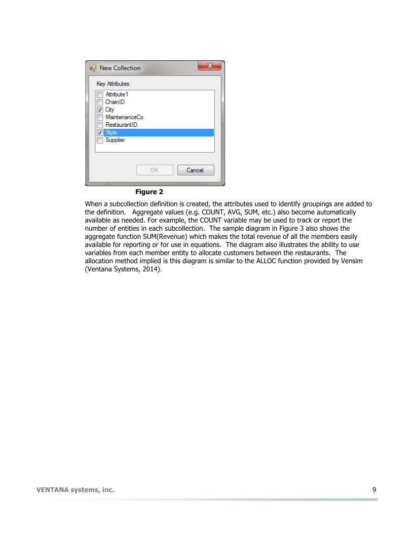
Figure 2 shows an example of how a specific subcollection could be added to a model of restaurants. The user selects which attribute or attributes to use in defining the subcollection.
When the model is simulated, one subcollection is created for each combination that has at least one entity. In this case, we select City and Style for groupings.
VENTANA systems, inc. 9
Figure 2
When a subcollection definition is created, the attributes used to identify groupings are added to
the definition. Aggregate values (e.g. COUNT, AVG, SUM, etc.) also become automatically available as needed. For example, the COUNT variable may be used to track or report the
number of entities in each subcollection. The sample diagram in Figure 3 also shows the
aggregate function SUM(Revenue) which makes the total revenue of all the members easily available for reporting or for use in equations. The diagram also illustrates the ability to use
variables from each member entity to allocate customers between the restaurants. The allocation method implied is this diagram is similar to the ALLOC function provided by Vensim
(Ventana Systems, 2014).

VENTANA systems, inc. 10
Figure 3
References
A key advantage of a system dynamics model is the ability to represent causality as it exists between any parts of the system. In order to connect parts of a disaggregated system, we
support the ability for entities to create references (causal or informational links) to other
entities. Using these references, equations and other specifications for an entity are able to access the values of variables from any referenced entity. For example, a business entity could
access tax rates and unemployment information for its home state as well as a national tax rate. A person entity could reference peers in a network. Figure 4 shows three example entity types:
Business, State, and National. Reference attributes have been added to the business so that it
could reference one corresponding entity for each of the other two types. The desired information variables may be placed on the diagram and connected to the “Profit After Tax”
variable.

VENTANA systems, inc. 11
Figure 4
The equation dialog illustrates how these references are represented in equations. In a manner
similar to many object-oriented languages, the reference name and variable name are separated by a dot (period). The equation editor provides auto-lookup and auto-completion capabilities to
minimize the need for typing. These features also help reduce “typos” and undefined variable errors.
In order to use a reference, each entity must have a value for the attribute(s) needed to find the
correct target entity, such as a State or a Nation. In this example, the reference would likely remain static for the entire simulation. However, if a business were to relocate and change its
home state, the platform would automatically adjust the references accordingly.
VENTANA systems, inc. 12
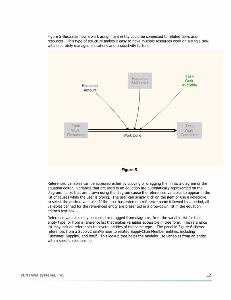
Figure 5 illustrates how a work assignment entity could be connected to related tasks and
resources. This type of structure makes it easy to have multiple resources work on a single task with separately managed allocations and productivity factors.
Figure 5
Referenced variables can be accessed either by copying or dragging them into a diagram or the
equation editor. Variables that are used in an equation are automatically represented on the diagram. Links that are drawn using the diagram cause the referenced variables to appear in the
list of causes while the user is typing. The user can simply click on the item or use a keystroke to select the desired variable. If the user has entered a reference name followed by a period, all
variables defined for the referenced entity are presented in a drop-down list in the equation
editor’s text box.
Reference variables may be copied or dragged from diagrams, from the variable list for that
entity type, or from a reference list that makes variables accessible in tree form. The reference list may include references to several entities of the same type. The panel in Figure 6 shows
references from a SupplyChainMember to related SupplyChainMember entities, including
Customer, Supplier, and itself. This lookup tree helps the modeler use variables from an entity with a specific relationship.

VENTANA systems, inc. 13
Figure 6
Figure 7 illustrates two additional types of references. Restaurant[City, Style] represents the
subcollection of all restaurants with the same City and Style as the individual restaurant. This
reference can be used to access aggregate information about competitors. The reference to State is using the City attribute to reference the correct State entity.

VENTANA systems, inc. 14
Figure 7
Relationship Entities
Relationship entities are used to model the relationship between two or more other entities. The Relationship entity must contain attribute variables that identify specific entities or collections of
entities. Stock and attribute variables control the relationship logic and may also be used to store relationship history or status.
For example, a market with multiple buyers and suppliers might contain a collection of
relationship entities that express which buyers are connected to which suppliers. If relationships are transient, one might think of the collection as an Order Book, with members that exist only as
long as there is an open transaction between a buyer and a seller.
Lists of relationship entities support efficient storage of relationships when entities may have
relationships with multiple entities of a particular type but where the “array” of relationships is
sparsely populated. This is a significant improvement versus system dynamics arrays or spreadsheets which become very large as the number of members increases. Relationships may
involve two entities of the same type (e.g. Task to Task precedence) and may sometimes include more than two entities.
Sparse Matrix Issues
The sparse matrix problem may exist when the modeler needs components with multiple
distinguishing attributes. Current system dynamics tools are usually restricted to multi-
dimensional arrays. When these arrays model real-world items, some or most of the array elements are not used – hence the term sparse array.
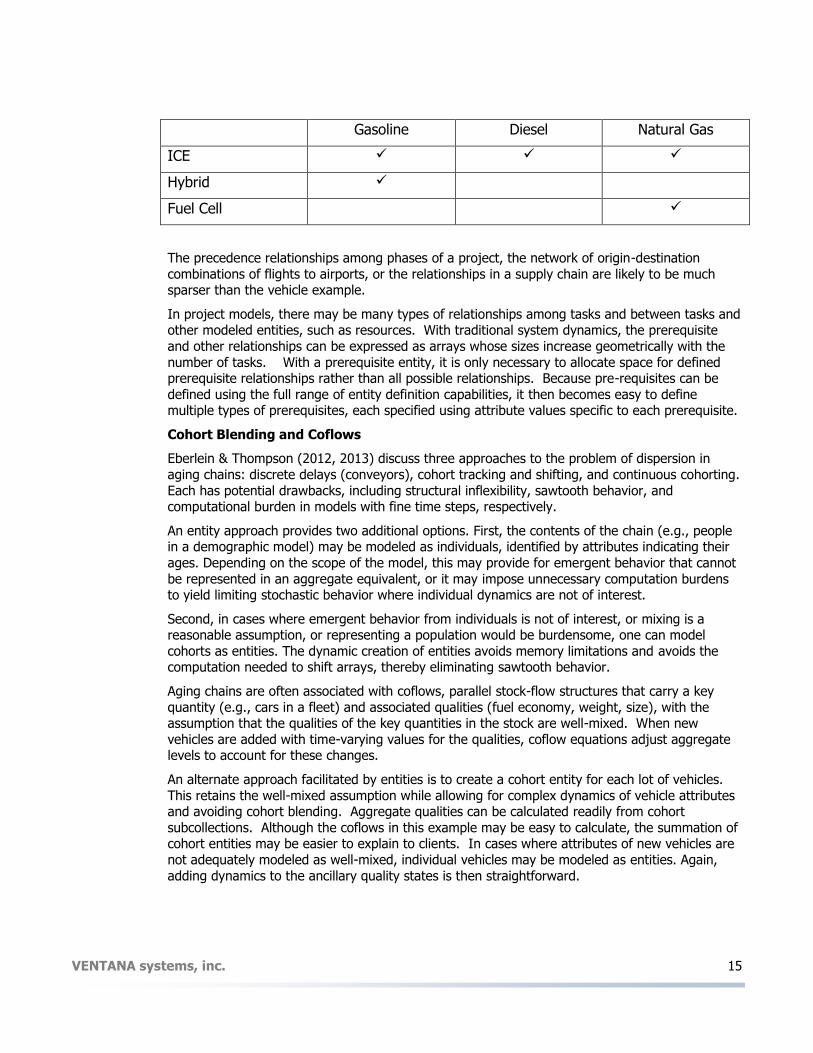
For example, one can categorize vehicles by fuel type (gasoline, diesel, natural gas) and propulsion technology (internal combustion, hybrid, and fuel cell). But in practice, many elements
of the matrix of vehicle combinations may not exist.
VENTANA systems, inc. 15
Gasoline Diesel Natural Gas
ICE
Hybrid
Fuel Cell
The precedence relationships among phases of a project, the network of origin-destination
combinations of flights to airports, or the relationships in a supply chain are likely to be much sparser than the vehicle example.
In project models, there may be many types of relationships among tasks and between tasks and other modeled entities, such as resources. With traditional system dynamics, the prerequisite
and other relationships can be expressed as arrays whose sizes increase geometrically with the
number of tasks. With a prerequisite entity, it is only necessary to allocate space for defined prerequisite relationships rather than all possible relationships. Because pre-requisites can be
defined using the full range of entity definition capabilities, it then becomes easy to define multiple types of prerequisites, each specified using attribute values specific to each prerequisite.
Cohort Blending and Coflows
Eberlein & Thompson (2012, 2013) discuss three approaches to the problem of dispersion in
aging chains: discrete delays (conveyors), cohort tracking and shifting, and continuous cohorting.
Each has potential drawbacks, including structural inflexibility, sawtooth behavior, and computational burden in models with fine time steps, respectively.
An entity approach provides two additional options. First, the contents of the chain (e.g., people in a demographic model) may be modeled as individuals, identified by attributes indicating their
ages. Depending on the scope of the model, this may provide for emergent behavior that cannot
be represented in an aggregate equivalent, or it may impose unnecessary computation burdens to yield limiting stochastic behavior where individual dynamics are not of interest.
Second, in cases where emergent behavior from individuals is not of interest, or mixing is a reasonable assumption, or representing a population would be burdensome, one can model
cohorts as entities. The dynamic creation of entities avoids memory limitations and avoids the computation needed to shift arrays, thereby eliminating sawtooth behavior.
Aging chains are often associated with coflows, parallel stock-flow structures that carry a key
quantity (e.g., cars in a fleet) and associated qualities (fuel economy, weight, size), with the assumption that the qualities of the key quantities in the stock are well-mixed. When new
vehicles are added with time-varying values for the qualities, coflow equations adjust aggregate levels to account for these changes.
An alternate approach facilitated by entities is to create a cohort entity for each lot of vehicles.
This retains the well-mixed assumption while allowing for complex dynamics of vehicle attributes and avoiding cohort blending. Aggregate qualities can be calculated readily from cohort
subcollections. Although the coflows in this example may be easy to calculate, the summation of cohort entities may be easier to explain to clients. In cases where attributes of new vehicles are
not adequately modeled as well-mixed, individual vehicles may be modeled as entities. Again,
adding dynamics to the ancillary quality states is then straightforward.
VENTANA systems, inc. 16
Actions
Policy models for complex systems will often require dynamically varying structure. For example, a regional economic model might need to create businesses, disband business, and add new
facilities. Modelers may want to conditionally change attribute values for existing entities in order to change relationships, aggregation, or logical processing. In still other cases, the model may
need to sequence certain processing inside the context of a single time period (DT or Time Step).
All of these capabilities are supported using a new construction called Actions.
Actions are model components that provide support for certain discrete event and agent-based
capabilities within the context of a continuous dynamic model. Actions can be used to package transactions or flows that must occur together in order for an internally consistent change of the
model state to occur; for example, double entry bookkeeping in a financial model. Actions can simulate a wide range of operations such as creating new entities, making investments, placing
orders, or finding oil.
During simulation, all required calculations are processed for every active entity. Actions, however, are only processed when scheduled or invoked by other actions. The scheduled
execution time for an action may be any explicit time during the simulation. Actions may also be scheduled to be processed at the beginning or end of every time period.
A new action is defined by adding an Action to an existing entity type definition. The action is
not limited to the parent entity and may even create or delete entities. The properties for an action are accessed through a dialog box and include:
Schedule: Immediate, Start of Period, End of Period, Scheduled time, On Create Conditions: Logical expressions that determine whether the Action is executed
New Entity Type: If an entity is to be created Number to Create:
Action Name:
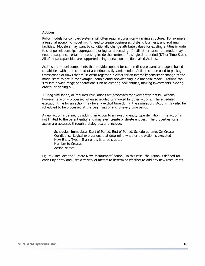
Figure 8 includes the “Create New Restaurants” action. In this case, the Action is defined for
each City entity and uses a variety of factors to determine whether to add any new restaurants.

VENTANA systems, inc. 17
Figure 8
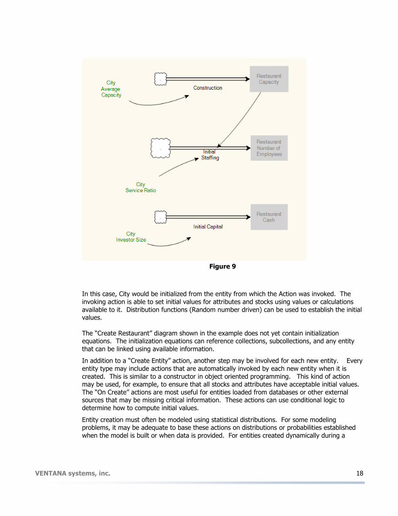
The action can then be defined using a separate diagram. If the action type is “Create Entity”, the diagram is pre-populated with the variables that need to be initialized (Stock and Attributes).
The user may add variables to an action to calculate intermediate values. Figure 9 illustrates
how an action can use stock and flow diagrams to initialize the values of new entities.
VENTANA systems, inc. 18
Figure 9
In this case, City would be initialized from the entity from which the Action was invoked. The
invoking action is able to set initial values for attributes and stocks using values or calculations
available to it. Distribution functions (Random number driven) can be used to establish the initial values.
The “Create Restaurant” diagram shown in the example does not yet contain initialization equations. The initialization equations can reference collections, subcollections, and any entity
that can be linked using available information.
In addition to a “Create Entity” action, another step may be involved for each new entity. Every
entity type may include actions that are automatically invoked by each new entity when it is
created. This is similar to a constructor in object oriented programming. This kind of action may be used, for example, to ensure that all stocks and attributes have acceptable initial values.
The “On Create” actions are most useful for entities loaded from databases or other external sources that may be missing critical information. These actions can use conditional logic to
determine how to compute initial values.
Entity creation must often be modeled using statistical distributions. For some modeling problems, it may be adequate to base these actions on distributions or probabilities established
when the model is built or when data is provided. For entities created dynamically during a

VENTANA systems, inc. 19
simulation, initial attributes may be assigned from dynamically updated distributions of its
contemporary population of like entities (maintained and managed by the collection representing the active populations of respective entity types). The platform provides the option to use
distributions calculated from collections so that newly created entities can be based on the best information at that point in time. These capabilities are implemented as built-in functions.
Actions are also able to delete or disable existing entities. Entities are logically deleted from the
active system structure, not physically deleted from memory. Thus, they are available for reference if the model uses look-back logic to refer to past values of variables. Create and
Delete functionality may be combined in one action to merge existing entities or to split an entity into multiple entities. Actions can also be linked to changes in entity information to update
relationships and attribute settings.
Team Modeling Support
Typical models are monolithic—there is just one computer file, and it contains the model. In
practical terms, this is a severe restriction on the number of people who can productively collaborate to develop and use a model, and hence a restriction on the scope of problems
addressable by a simulation analysis. Software development environments have long had support for team efforts, with modularization and automated software builds. Similar tools have
been developed around Vensim (Thompson & Bush 2005, Helfrich & Bush, 2008).
In the new platform, each entity type definition is stored separately from all other entity type definitions – either in XML files or in multi-user database tables. Entity type definitions are
connected to other entity type definitions by name. This allows the use of alternate implementations or versions of some or all of the entity type definitions. The model background
can be “filled-in” by various modelers or groups. This modular design approach minimizes the difficulty of keeping multiple development groups “in sync”.
Most model executions will include data tables that initialize some or all of the entities for a
model. These data tables may be modified or replaced by any stakeholder, expert, or observer with access to the model. Furthermore, all of the logic is transparent (with the exception of user-
compiled functions, which we have yet to explain). Multiple groups could make changes to the same entity as part of model analysis and experimentation.
The platform keeps a version history of the model used to generate specific scenarios, to provide
convenient backing up and analysis. The concentration of entity logic in a small number of diagrams will make it easier for non-modeler subject matter experts to review and contribute to
model logic. Interested observers (with proper access authority) will be able to include alternate equations as part of scenario definition.
Example Application
As an example, consider the C-ROADS model (http://climateinteractive.org/simulations/C-ROADS, Sterman et al. 2012). It translates country emissions commitments into global climate outcomes
and is used by decision makers in US and foreign agencies. It was developed in Vensim by a partnership of Climate Interactive, MIT, Ventana Systems and others.
There are several challenges involved in construction of the model with traditional tools:
1. Emissions scenario input may be entered at, or aggregated to, varying, possibly
overlapping, regional levels.

VENTANA systems, inc. 20
2. Decision input is desired in different modes; executing code for modes of entry that are
inactive is wasteful.
3. Multiple team members manage different portions of the model, but the model must be
run in its entirety.
4. Quality control requires calibration and testing of subsystems in isolation.
The C-ROADS model, implemented with the entity platform we describe, might look and work as
follows. Notably, this is a traditional SD model, without agent detail, employing entities to provide
modularity and flexibility. Nevertheless, it requires some of the same infrastructure needed to manage populations or networks of agents.
The C-ROADS model would become a top-level Entity Type Definition, a.k.a. “the model”. This would contain other entity type definitions that organize the structure of the model into sectors.
The top-level model entity might also contain global data and variables, not shown.
Figure 10. C-ROADS model top-level entity, showing relationships among component entities:
Team members could begin to assemble the model by first creating interfaces or templates for the entity type definitions needed, containing attributes and key variables that cross entity
boundaries, but lacking internal dynamics. The construction of entities could then proceed in parallel, with individual team members taking responsibility for particular entities, and populating
them with stocks, flows, data, etc. as needed to yield an executable model.
Most of the sector entities would be singletons, i.e. entity types for which only a single instance will exist. For example, the current C-ROADS model contains global aggregate greenhouse gas
cycles, climate, and other processes. There is no compelling reason to disaggregate these components.
VENTANA systems, inc. 21
On the other hand, the multiple countries and regions are designated as entities in a collection.
There are two ways one might design this. In a simple case, where each country belongs to exactly one region, one could identify each Country Emissions entity with a region attribute,
which would then be used to aggregate emissions by region.
However, in some cases, it would be useful to have multiple overlapping regions. For example
France might be a member of the OECD and of the EU for different accounting purposes. For
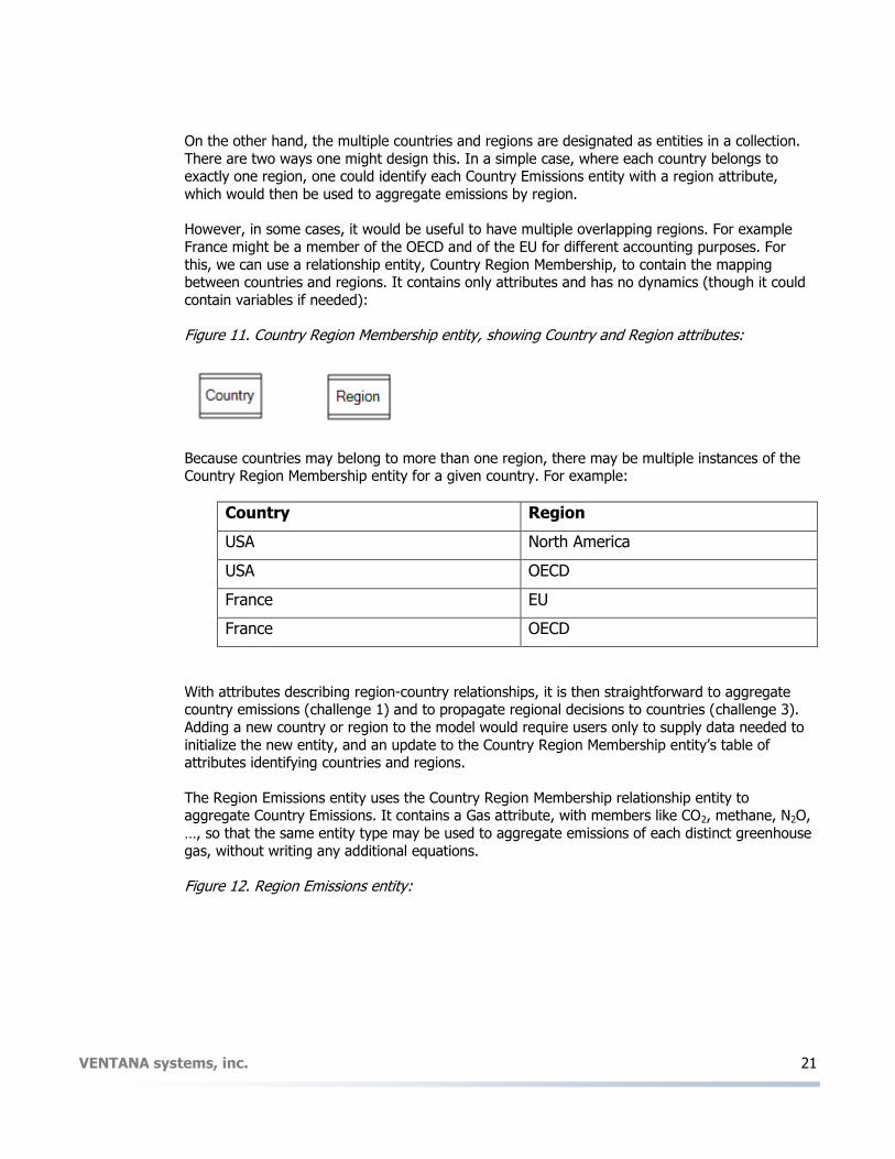
this, we can use a relationship entity, Country Region Membership, to contain the mapping between countries and regions. It contains only attributes and has no dynamics (though it could
contain variables if needed):
Figure 11. Country Region Membership entity, showing Country and Region attributes:
Because countries may belong to more than one region, there may be multiple instances of the Country Region Membership entity for a given country. For example:
Country Region
USA North America
USA OECD
France EU
France OECD
With attributes describing region-country relationships, it is then straightforward to aggregate country emissions (challenge 1) and to propagate regional decisions to countries (challenge 3).
Adding a new country or region to the model would require users only to supply data needed to
initialize the new entity, and an update to the Country Region Membership entity’s table of attributes identifying countries and regions.
The Region Emissions entity uses the Country Region Membership relationship entity to aggregate Country Emissions. It contains a Gas attribute, with members like CO2, methane, N2O,
…, so that the same entity type may be used to aggregate emissions of each distinct greenhouse
gas, without writing any additional equations.
Figure 12. Region Emissions entity:

VENTANA systems, inc. 22
In addition, the Region Emissions entity may contain a Region Emissions Policy entity type, which
defines an emissions trajectory at a regional rather than country level, as an EU policy might apply to member countries. The Region Emissions Policy entity acquires an attribute, Region,
from its parent, and defines a Region Emissions Trajectory (ordinarily this variable would have complex dynamics, but we do not elaborate upon its structure here). While it could stand alone,
it is encapsulated within the region for clarity.
The Country Entity generates emissions scenarios. It combines Historic Emissions, from data, with future scenarios generated by different methods. Two methods, Emissions by Intensity and
Emissions by BAU, are calculated within entities that are members of the Country Entity. Depending on the Active Decision Mode (a variable switch), it may not be necessary to create
both the Emissions by Intensity and Emissions by BAU entities, saving computation time if only one mode is needed (challenge 2).
A third method derives country emissions from regional policy, using the Region Emissions
Trajectory from the Regional Emissions Policy entity owned by an associated Region Emissions entity. As in the Region Emissions entity, the Country Region Membership relationship entity is
used to determine which regional policy is mapped to a given country.

VENTANA systems, inc. 23
Figure 13 Regional Emissions
Like the Region Emissions entity type, the Country Emissions entity type contains a Gas attribute, so that the same structure may be used for each distinct greenhouse gas, without writing any
additional equations.
Once country emissions have been simulated, and aggregated to regions, including global, the
global biogeochemical cycles may be calculated.
The Methane Cycle entity, for example, takes Natural Emissions from a data source, combines and combines them with Anthropogenic Emissions from the Region Emissions entity. Since only
global emissions are needed to drive the methane cycle, it refers to the Anthropogenic Emissions from the Region Emissions entity, selecting the methane Gas instance for the global region. It
then computes the dynamics of Atmospheric Methane. For visual simplicity and organization, the complexities of atmospheric chemistry that govern the variable atmospheric lifetime of methane
are collapsed into the Hydroxyl Chemistry group.

VENTANA systems, inc. 24
Figure 14 Methane Cycle Entity
The methane cycle, like other entity type definitions in the model, may be stored separately,
facilitating version control and collaboration (challenge 4) via file-based synchronization or source control systems, or via storage of the entity and its history in a multiuser database. This would
permit a person with relevant biogeophysical expertise to maintain the methane cycle, while other team members with economic or political expertise maintained country and region
emissions entities.
The methane cycle may be run in isolation from the remainder of the model. This permits extreme conditions or equilibrium testing, unencumbered by the overhead of executing the
remainder of the model. It also permits rapid execution for automated recalibration of parameters within the Hydroxyl Chemistry group, in response to new data or structural changes
to the model. Assembly of other portions of the model, like the Climate entity type definition,
proceeds using the same concepts.
A significant effort is required to maintain data on historic country emissions, stated future
policies, global atmospheric GHG concentrations, temperature, and other variables. These inputs are best maintained in a database. The platform provides access to this data. The connection is
facilitated because the structure of collections of entities with attributes naturally matches the structure of relational database tables.
Conclusion
This paper has analyzed the challenges facing the application of system dynamics to large and complex systems. These challenges include the need to manage large, disaggregated systems
and for the models to simulate dynamic changes in structure. The cost and difficulty of building and using models of complex systems limits the number of attempts and also limits the
effectiveness of those models that are developed. The cost of hybrid methodologies is increased
because of the need to develop technical interfaces as part of the modeling project.

VENTANA systems, inc. 25
We concluded that the fundamental shift to an object-oriented architecture required new
development rather than structure superimposed on existing system dynamics toolsets. This paper provides an overview of a new platform for building modular models of complex dynamic
systems. It enables new techniques and improved approaches to the representation of real world systems. We expect that modelers will find innovative ways to combine these capabilities
in ways to expand and improve the scope of system dynamics.

VENTANA systems, inc. 26
Bibliography
C. Bauer and F. Bodendorf (2006). Enhancing System Dynamics Modeling Using a Component-Based Approach. International Journal of Simulation Vol 7 No 6.
B. Behdani (2012). Evaluation of Paradigms for Modeling Supply Chains as Complex Socio-Technical Systems. Proceedings of the 2012 Winter Simulation Conference.
R. Eberlein and J. Hines (1996). Molecules for modelers. Proceedings of the International System
Dynamics Society. Cambridge: System Dynamics Society.
R. L. Eberlein and J. P. Thompson (2012). Chronological Aging in Continuous Time. The 30th
International Conference of the System Dynamics Society
R. L. Eberlein and J. P. Thompson (2013). Precise modeling of aging populations. System
Dynamics Review, 29: 87–101. doi: 10.1002/sdr.1497
K. Eubanks and L. Yeager (2001). An Introduction to Jitia: Simulation Software Designed for
Developing Large Models. The 19th International Conference of the System Dynamics Society
N. Gilbert and P. Terna. (2000). “How to Build and Use Agent-Based Models in Social Science”, Mind
and Society 1: 57 – 72.
N. Helfrich and W. Schade (2008) Bringing distributed software development to SD modelling
with Vensim. The 26th International Conference of the System Dynamics Society.
M. Myrtveit (2000). Object Oriented Extensions to System Dynamics. The 18th International
Conference of the System Dynamics Society
N. Osgood. (2009). Silver: Software in support of the system dynamics modeling process. The 27th International Conference of the System Dynamics Society
N. Osgood and Y. Tian, (2012). 15 Things System Dynamics can Learn from Software Development. The 30th International Conference of the System Dynamics Society.
N. Schieritz (2002). Integrating System Dynamics and Agent-Based Modeling. The 20th
International Conference of the System Dynamics Society
N. Schieritz and P. Milling (2003). Modeling the Forest or Modeling the Trees: A Comparison of
System Dynamics and Agent-Based Simulation. The 21st International Conference of the System Dynamics Society
N. Schieritz and A. GroBler (2003). Emergent structures in supply chains - a study integrating agent-based and system dynamics modeling. Proceedings of the 34th Annual Hawaii
International Conference on System Sciences
H. Scholl (2001). Agent-Based and Systems Dynamics Modeling: A Call for Cross-Study and Joint Research. 34th Annual Hawaii International Conference on System Sciences
J. Sterman (2000). Business Dynamics: Systems thinking and modeling for a complex world. McGraw Hill.
J. Sterman, T. Fiddaman, T. Franck, A. Jones, S. McCauley, P. Rice, E. Sawin, and L. Siegel
(2012), Climate interactive: the C-ROADS climate policy model. System Dynamics Review, 28: 295–305. doi: 10.1002/sdr.1474
VENTANA systems, inc. 27
M. Teose, K. Ahmadizadeh, E. O’Mahony, R. L. Smith, Z. Lu, S. P. Ellner, C. Gomes, Y. Grohn
(2011). Embedding System Dynamics in Agent Based Models for Complex Adaptive Systems. Proceedings of the Twenty-Second International Joint Conference on Artificial Intelligence
D. Thompson and B. Bush (2005). Software Practices Applied to System Dynamics: Support for Large Scale Group Development. The 23rd International Conference of the System Dynamics
Society
W. Tignor (1999). System Dynamics Models and the Object-Oriented Paradigm. The 17th International Conference of the System Dynamics Society
W. Tignor (2004) System Engineering and System Dynamics Models. The 22nd International Conference of the System Dynamics Society
W. Tignor and M. Myrtveit (2000). Object-Oriented Design Patterns and System Dynamics Components. The 18th International Conference of the System Dynamics Society
Ventana Systems, Inc (2013). Vensim Reference Manual.