enterprise architect import - unified modeling … enterprisearchitectimportplugin...
TRANSCRIPT

ENTERPRISE ARCHITECT IMPORT
user guide
No Magic, Inc.
2013

All material contained herein is considered proprietary information owned by No Magic, Inc. and is not to be shared, copied, or reproduced by any means. All information copyright 1998-2013 by No Magic, Inc.

C O N T E N T S
1. Introduction 52. Plugin Information 63. Working with Enterprise Architect Import Plugin 6
3.1 Conversion Options 83.2 Conversion Messages 10
4. Transforming EA Specific Data 104.1 Constraints 114.2 Requirements 124.3 Scenarios 124.4 Files 124.5 Requirements (External) 134.6 Changes 134.7 Issues 13
5. Importing Diagrams 155.1 Geometry Properties 155.2 Color Properties 155.3 Display Properties 15
6. Special Transformation 166.1 Use Case Diagram Elements 16
6.1.1 Actor with Properties 166.1.2 Use Case with Invalid Inner Elements 176.1.3 Boundary 17
6.2 Activity Diagram Elements 186.2.1 Activity 186.2.2 Activity Diagram 196.2.3 Object as the Inner Element of an Activity 196.2.4 Synch Node 206.2.5 Activity Parameter 216.2.6 Exception Handler 226.2.7 ObjectFlow 236.2.8 ExpansionRegion 236.2.9 InterruptibleActivityRegion 256.2.10 Swimlane 256.2.11 StructuredActivity 266.2.12 InterruptFlow 286.2.13 ExpansionNode 29
6.3 Sequence Diagram Elements 296.3.1 Lifelines 29
6.3.1.1 Gaps between Lifelines 296.3.1.2 Lifelines Arrangement 306.3.1.3 Class, Part, and Port 31
6.3.2 Gate 316.3.3 Endpoints 346.3.4 Delete Messages 356.3.5 Branch Messages 376.3.6 Boundaries, Controls, and Entities 386.3.7 Actors 396.3.8 General Ordering 41
Copyright © 1998-2013 No Magic, Inc.3

C O N T E N T S
6.3.9 State Invariant 426.3.10 Continuation 426.3.11 Diagonal Message 436.3.12 Synchronous Message Behavior 44
6.3.12.1 Order 446.3.12.2 Process 456.3.12.3 Activation Level 47
6.3.13 Asynchronous Message Behavior 476.3.14 Return Message Behavior 486.3.15 Activation Options 49
6.4 Communication Diagram Elements 496.4.1 Object, Boundary, Entity, and Control 496.4.2 Exception Elements 506.4.3 Realization and Nesting 516.4.4 Association 526.4.5 Message 546.4.6 Operations 55
6.5 State Machine Diagram Elements 566.5.1 StateMachine 566.5.2 State 57
6.5.2.1 State Containing Other Elements 576.5.2.2 State Containing StateMachine 576.5.2.3 State Containing Attribute and Operation 586.5.2.4 State Containing Diagram Element 59
6.5.3 StateMachine Placed on a Diagram 606.5.4 Object 61
6.5.4.1 Object Containing State Machine Element 626.5.5 Synch 636.5.6 EntryPoint / ExitPoint 646.5.7 Object Flow Connecting State Machine Elements 656.5.8 Information Flow Connecting State Machine Elements 666.5.9 Trigger 676.5.10 Self Transition 676.5.11 Removed Element 68
6.6 Composite Structure Diagrams 696.6.1 Import Elements 696.6.2 Conversion Details 70
6.6.2.1 Dummy Class 706.6.2.2 Class 706.6.2.3 Interface 726.6.2.4 Part 726.6.2.5 Port 756.6.2.6 Collaboration 776.6.2.7 Expose Interface 786.6.2.8 Package 816.6.2.9 Assembly 816.6.2.10 Dependency 826.6.2.11 Removed Relationships 82
6.6.3 Transformation Report 836.7 Interaction Overview Diagrams 84
6.7.1 Conversion Details 846.7.1.1 Interaction Overview Diagram 846.7.1.2 Interaction Element 856.7.1.3 Interaction Occurrence 87
7. Known Limitations and Constraints 88
4 Copyright © 1998-2013 No Magic, Inc.

ENTERPRISE ARCHITECT IMPORT PLUGIN FOR MAGICDRAW
1. IntroductionMagicDraw has the functionality to import UML models that conform to various XMI versions (including XMI 2.1) from Sparx Systems Enterprise Architect (EA), a modeling and visualization tool based on the UML 2.3 standard. EA has the ability to import and export XMI compliant models; therefore, you can use EA to import UML2.1(XMI2.1). However, the XMI models exported from EA contain some XMI conflicts and EA-specific data that do not conform to the UML standards.
Enterprise Architect Import Plugin for MagicDraw allows you to migrate the XMI models from EA to MagicDraw flawlessly by using an additional transformation process with a set of mapping rules.
The main purpose of Enterprise Architect Import Plugin is to help MagicDraw users who need to import models from EA by managing the conflicts that can cause problems during loading the XMI models to MagicDraw and transforming some EA-specific data into UML elements with stereotypes.
Apart from the ability to import model elements, the plugin also allows for the import of diagrams. The current plugin version supports:
• Class diagrams
• Package diagrams
• Object diagrams
• Component diagrams
• Deployment diagrams
• Use Case diagrams
• Activity diagrams
• Sequence diagrams
• Communication diagrams
• StateMachine diagrams
• CompositeStructure diagrams
• InteractionOverview diagrams
2. Plugin InformationEnterprise Architect Import Plugin for MagicDraw supports Enterprise Architect Versions 7.1, 7.5, and 8.0 (most of the testing procedures performed on EA 7.1.833 and EA 7.5.847). The plugin helps you import and transform an EA exported XMI using the UML2.1(XMI2.1) option into a MagicDraw file (*.mdxml).
Your imported models will include the following details:
• UML models
• Profiles
• Stereotype usage information
• EA-specific data:
• Constraints
Copyright © 1998-2013 No Magic, Inc.5

ENTERPRISE ARCHITECT IMPORT PLUGIN FOR MAGICDRAW
• Requirements
• Scenarios
• Files
• Requirements (External)
• Changes
• Issues
• Diagram information
• Class diagrams
• Package diagrams
• Object diagrams
• Component diagrams
• Deployment diagrams
• Use Case diagrams
• Activity diagrams
• Sequence diagrams
• Communication diagrams
• StateMachine diagrams
• CompositeStructure diagrams
• InteractionOverview diagrams
• SysML (SysML 1.1 model from EA will be transformed to MagicDraw SysML.)
3. Working with Enterprise Architect Import Plugin Enterprise Architect Import Plugin will be automatically loaded when you start MagicDraw.
To open the Import Enterprise Architect Files dialog:
6 Copyright © 1998-2013 No Magic, Inc..

ENTERPRISE ARCHITECT IMPORT PLUGIN FOR MAGICDRAW
• On the MagicDraw main menu, click File > Import From > Enterprise Architect UML2.1 XMI2.1 File (Figure 1). The Import Enterprise Architect Files dialog will open (Figure 2).
Figure 1 -- Enterprise Architect Import Menu
Figure 2 -- Import Enterprise Architect Files Dialog
7 Copyright © 1998-2013 No Magic, Inc..

ENTERPRISE ARCHITECT IMPORT PLUGIN FOR MAGICDRAW
Table 1 -- Import Enterprise Architect Files Dialog Properties
To import an EA project:
1. Either type an EA exported XMI file or click the “...” button to select the file (Figure 2).
2. Either type a MagicDraw output filename or click the “...” button to select the file.3. Select the conversion options.4. Click the Import button to start importing the file.
3.1 Conversion Options
Apart from the options that you have in the Import Enterprise Architect File dialog, you can also find several other conversion options in the MagicDraw Environment Options dialog.
To view the Enterprise Architect Import other options in the Environment Options dialog:
1. Click Option > Environment on the MagicDraw main menu. The Environment Options dialog will open (Figure 3).
2. Select Enterprise Architect Import from the tree menu on the left-hand side. The transforma-tion options are classified into two groups: (i) General and (ii) Activity element mapping.
Property name Function
EA exported XMI: UML 2.1(XMI 2.1)
To specify an EA exported XMI file. You can click the “...” but-ton to select the file.
MagicDraw output file name (*.mdxml)
To specify a MagicDraw output filename. You can click the “...” button to select the file.
Switch aggregation side To configure the aggregation switch-side. This option is rec-ommended for XMI files exported from EA 7.1.
Exclude EA specific data To exclude all EA-specific data from being imported (see “Transforming EA Specific Data” on page 10 to see a list of EA specific-data that can be transformed into UML elements with stereotypes).
Open project after conversion To load the output project file once the conversion process has been completed.
Generate conversion log To generate a conversion log and save it in the same folder as the MagicDraw output file. The same conversion information will also be displayed on the MagicDraw messages window.
NOTE Enterprise Architect Import Plugin supports the EA XMI files exported with the option specified as: XMI Type = UML2.1(XMI 2.1).
8 Copyright © 1998-2013 No Magic, Inc..

ENTERPRISE ARCHITECT IMPORT PLUGIN FOR MAGICDRAW
Figure 3 -- Environment Options Dialog
(i) General
The options available in the General group are the same as those in the Import Enterprise Architect Files dialog.
(ii) Activity element mapping option
The Activity element mapping group provides you with the options to convert the EA elements to other element types.
9 Copyright © 1998-2013 No Magic, Inc..

ENTERPRISE ARCHITECT IMPORT PLUGIN FOR MAGICDRAW
Table 2 -- Activity Element Mapping Options
3.2 Conversion Messages
Enterprise Architect Import Plugin consists of a series of XMI conversions. Each conversion will be reported to the MagicDraw Messages window and also saved to a log file if the Generate conversion log option is selected.
The conversion log will be saved in the same directory as the MagicDraw output file using the same name but a different .log extension.
4. Transforming EA Specific DataBesides UML data, each EA-exported XMI also contains EA-specific information. Enterprise Architect Import Plugin can transform this particular information into UML elements with the stereotypes applied if you select to include EA-specific data before importing the XMI file. The EA-specific data that will be transformed include:
(4.1) Constraints: name, description, type, weight, and status
(4.2) Requirements: name, description, type, status, difficulty, priority, and last update
(4.3) Scenarios: name, description, type, and weight
(4.4) Files: file path type
(4.5) Requirements (External): type, status, difficulty, priority, last update, created, and note
(4.6) Changes: type, status, difficulty, priority, last update, created, and note
(4.7) Issues: type, status, difficulty, priority, last update, created, and note
Property name Function
Convert EA WriteVariableAc-tion to
To convert EA WriteVariableAction to either AddVariableV-alueAction or RemoveVariableValueAction.
Convert EA WriteLinkAction to To convert EA WriteLinkAction to either CreateLinkAction or DestroyLinkAction.
Convert EA WriteStructural-FeatureAction to
To convert EA WriteStructuralFeatureAction to either AddStructuralFeatureValueAction or RemoveStructuralFea-tureValueAction.
NOTE You can open the MagicDraw Messages window by pressing Ctrl + M.
NOTE You can access and specify the EA information in the Property dialog in EA.
10 Copyright © 1998-2013 No Magic, Inc..

ENTERPRISE ARCHITECT IMPORT PLUGIN FOR MAGICDRAW
To include the EA-specific data in the transformation process, the plugin will create a set of stereotypes and tag definitions as the EA Profile (Figure 4).
Figure 4 -- EA Profile
4.1 Constraints
Each EA constraint will be transformed into a UML constraint and <<EAConstraint>> will be applied to the constraint. The properties of an EA constraint will be mapped either to the properties of a UML constraint or to the tag values of <<EAConstraint>>. Table 3 below shows the constraints mapping details.
11 Copyright © 1998-2013 No Magic, Inc..

ENTERPRISE ARCHITECT IMPORT PLUGIN FOR MAGICDRAW
Table 3 -- Constraints Mapping
4.2 Requirements
Each EA requirement will be transformed into a UML Class. In EA, since a requirement cannot be created in an element, which is the owner of a Class, the transformed requirement will be kept in a separate Package, named EA Requirement, and a Realization will be created from the owner of the requirement into a transformed requirement. See Table 4 below for details.
Table 4 -- Requirements Mapping
4.3 Scenarios
Each EA scenario will be transformed into a UML Comment and <<EAScenario>> will be applied to the com-ment. The properties of a scenario will be mapped either to the properties of each UML Comment or to the tag values of <<EAScenario>>. See Table 5 below for details.
Table 5 -- Scenarios Mapping
4.4 Files
EA is capable of adding files to a UML element. The information will be transformed into a Hyperlink in Magic-Draw.
EA MagicDraw
name The name property of a UML constraint.
description EAConstraint::type tag value
type EAConstraint::weight tag value
weight EAConstraint::status tag value
Constraint owner Constrained Element property point to the constraint owner.
EA MagicDraw
name EARequirement :: name tag value
description EARequirement :: description tag value
type EARequirement :: type tag value
status EARequirement :: status tag value
difficulty EARequirement :: difficulty tag value
priority EARequirement :: priority tag value
last update EARequirement :: name update value
EA MagicDraw
name EAScenario::name tag value
description The Body property of a UML Comment.
type EAScenario::type tag value
weight EAScenario::weight tag value
subject An annotated Element property pointing to an EA subject element.
12 Copyright © 1998-2013 No Magic, Inc..

ENTERPRISE ARCHITECT IMPORT PLUGIN FOR MAGICDRAW
Table 6 -- Files Mapping
4.5 Requirements (External)
A Requirement created by EA is different from the one you create as an internal element for each element. EA requirements will appear in the Project Browser and can be pasted on a diagram. Each EA Requirement will be transformed into a Class and <<EARequirement>> will be applied to the requirement.
Table 7 -- Requirements (External) Mapping
4.6 Changes
EA can create a Change and will export it as a Class. The Class information will be transformed into the <<EAChange>> tag values. See Table 8 below for details.
Table 8 -- Changes Mapping
4.7 Issues
EA can create an Issue and will export it as a Class. The Issue information will be transformed into the <<EAIssue>> tag values. See Table 9 below for details.
Table 9 -- Issues Mapping
EA MagicDraw
Local file File
Web address Web page
EA MagicDraw
type EARequirement::type tag value
status EARequirement::status tag value
difficulty EARequirement::difficulty tag value
priority EARequirement::priority tag value
last update EARequirement::last update tag value
created EARequirement::created tag value
note Documentation
EA MagicDraw
type EAChange::type tag value
status EAChange::status tag value
difficulty EAChange::difficulty tag value
priority EAChange::priority tag value
last update EAChange::last update tag value
created EAChange::created tag value
note Documentation
EA MagicDraw
type EAIssue::type tag value
13 Copyright © 1998-2013 No Magic, Inc..

ENTERPRISE ARCHITECT IMPORT PLUGIN FOR MAGICDRAW
status EAIssue::status tag value
difficulty EAIssue::difficulty tag value
priority EAIssue::priority tag value
last update EAIssue::last update tag value
created EAIssue::created tag value
note Documentation
EA MagicDraw
14 Copyright © 1998-2013 No Magic, Inc..

ENTERPRISE ARCHITECT IMPORT PLUGIN FOR MAGICDRAW
5. Importing DiagramsEnterprise Architect Import Plugin allows you to import diagrams. The diagram information that will be imported include:
(5.1) Geometry properties
(5.2) Color properties
(5.3) Display properties
5.1 Geometry Properties
The geometry properties that will be imported to MagicDraw are as follows:
• Positions on a diagram (for shape elements)
• Width and height (for shape elements)
• Path break points (for link elements)
5.2 Color Properties
The color properties will be imported along with the diagrams to MagicDraw. The name of each color property is called differently in MagicDraw.
Table 10 -- Color Properties Mapping
5.3 Display Properties
The display properties in EA can be categorized into three groups: (i) shape, (ii) link, and (iii) diagram proper-ties. Only those that have similar properties to the MagicDraw’s will be imported, for example, the Show Dia-gram Details property in EA will be imported as the Show Diagram Info property in MagicDraw.
NOTE Geometry information can be overridden by other display properties. For example, if an imported element width is shorter than the required width to display text on the element, the width will be adjusted automat-ically.
EA MagicDraw
Background color Fill color
Border color (for shape ele-ment)
Pen color
Font color Text color
Line color (for link element) Pen color
15 Copyright © 1998-2013 No Magic, Inc..

ENTERPRISE ARCHITECT IMPORT PLUGIN FOR MAGICDRAW
6. Special TransformationAn EA-exported XMI contains some non-standard UML elements and many elements that can break the XMI schema. To retain the standard UML elements and keep the XMI schema intact, Enterprise Architect Import Plugin applies some particular transformation rules. The following sections will describe how the plugin trans-forms each model element so that you can import a complete XMI model that conforms to the UML standards.
6.1 Use Case Diagram Elements
6.1.1 Actor with Properties
An Actor with properties will be transformed into a Class with the EAActor stereotype (Figure 5).
Figure 5 -- Actor with Property
NOTE An Actor that has been converted to a Class with <<EAActor>> will not display some properties accordingly such as Fill Color because the stereotype image will be shown instead.
16 Copyright © 1998-2013 No Magic, Inc..

ENTERPRISE ARCHITECT IMPORT PLUGIN FOR MAGICDRAW
6.1.2 Use Case with Invalid Inner Elements
A NestedClassifier, ownedComment, ownedRule, ownedAttribute, or ownedOperation cannot be an inner ele-ment of a uml:UseCase. It will be moved to a new created realized Class.
Figure 6 -- Use Case with Invalid Inner Elements
6.1.3 Boundary
A boundary in EA will be converted into a rectangle with rounded corners in MagicDraw. The boundary can contain inner elements. Unlike the rectangular boundary in MagicDraw, the boundary in EA will take all the inner elements with it whenever it is moved (Figure 7).
Figure 7 -- Boundaries
17 Copyright © 1998-2013 No Magic, Inc..

ENTERPRISE ARCHITECT IMPORT PLUGIN FOR MAGICDRAW
6.2 Activity Diagram Elements
6.2.1 Activity
An Activity element in EA can be directly placed as an element view on an Activity diagram. However, this behavior conflicts with the MagicDraw and UML notation. In MagicDraw, if you drag an Activity from the con-tainment tree to an Activity diagram, a new CallBehaviorAction view will be created and the 'Behavior' property of the CallBehaviorAction will be set to the Activity. This same behavior will be used in the import process.
An Activity element created in EA, which is placed on an Activity diagram, will be transformed into two ele-ments: (i) Activity, and (ii) CallBehaviorAction elements. Both of them will have the same name and will be linked through the property of a CallBehaviorAction element called 'Behavior'.
After the element has been transformed, the following transformation message will open:
Updated element <xmi:id>: A new CallBehaviorAction was created and its Behavior was set to the element.
Figure 8 -- EA Activity
Figure 9 -- Activity with a New CallBehavior in MagicDraw
18 Copyright © 1998-2013 No Magic, Inc..

ENTERPRISE ARCHITECT IMPORT PLUGIN FOR MAGICDRAW
Additionally, any ObjectNode elements that are attached to the Activity element will be transformed into Input-Pin elements and attached to the newly created CallBehaviorAction element (Figure 10).
Figure 10 -- An ObjectNode Converted into an InputPin
6.2.2 Activity Diagram
Every Activity Diagram element from EA will be placed inside an Activity element that has the same name (Fig-ure 11).
Figure 11 -- Activity diagram placement in MD
6.2.3 Object as the Inner Element of an Activity
Object elements, which are inside an Activity element in EA, will be removed (Figure 12).
NOTE The EA Activity and CallBehaviorAction elements have a similar characteristic, that is, you can attach a control flow to it and others. EA has its own CallBehav-iorAction element.
NOTE In MagicDraw, every Activity diagram element must be placed inside an Activity element that has the same name, but this is not the case in EA.
19 Copyright © 1998-2013 No Magic, Inc..

ENTERPRISE ARCHITECT IMPORT PLUGIN FOR MAGICDRAW
Figure 12 -- Object Element Transformation
An Object element that contains any ActivityDiagram-related elements will be removed (Figure 13).
Figure 13 -- Object Containing Activity-related Elements
6.2.4 Synch Node
A Synch element in EA will be transformed into a Join element in MagicDraw and it will look exactly like a Fork/Join element (Figure 14).
NOTE Object elements in MagicDraw have their XMI types defined as 'uml:Central-BufferNode' but, those in EA have their XMI types defined as 'uml:Instance-Specification', which do not belong to an Activity diagram.
Note In MagicDraw, an Object element (CentralBufferNode) is not allowed to contain any other elements besides comments and hyperlinks.
20 Copyright © 1998-2013 No Magic, Inc..

ENTERPRISE ARCHITECT IMPORT PLUGIN FOR MAGICDRAW
Figure 14 -- Synch Element
6.2.5 Activity Parameter
If you create an ActivityParameter element, MagicDraw will automatically create an ActivityParameterNode ele-ment to represent it. Every ActivityParameterNode element in EA will be transformed into a Pin element (Fig-ure 15).
Figure 15 -- ActivityParameterNode
There are four parameter types that you can specify for each Activity Parameter element: (i) in, (ii) out, (iii) inout, and (iv) return.
The ActivityParameterNode element of an ActivityParameter element, whose parameter type is either 'in' or 'inout', will be transformed into an InputPin element. The ActivityParameterNode element of an ActivityParame-ter element, whose parameter type is either 'out' or 'return', will be transformed into an OutputPin element (Fig-ure 16).
Note A MagicDraw Fork/Join element (whose type is uml:ForkNode) can be used to construct either a Fork and Join node in an Activity diagram. The JoinNode ele-ment (whose type is uml:JoinNode) is allowed to be placed in the Activity dia-gram, but the element’s image will be displayed as the Fork/Join element’s default image.
21 Copyright © 1998-2013 No Magic, Inc..

ENTERPRISE ARCHITECT IMPORT PLUGIN FOR MAGICDRAW
Figure 16 -- ActivityParameter Type
6.2.6 Exception Handler
The Exception Handler element in EA is different from the UML’s ExceptionHandler. This EA element will be transformed into a CallBehaviorAction element. Any ObjectNode element that is attached to it will be trans-formed into an InputPin element and any InterruptFlow line will be transformed into an ExceptionHandler line in MagicDraw (Figure 17).
After the transformation has been completed, the following transformation messages will open:
• Updated element <xmi:id>: EA ExceptionHandler is transformed to an CallBehaviorAction with and input pin.
• Updated element <xmi:id>: EA InterruptFlow was transformed to an ExceptionHandler.
Note Usually, if you specify the parameter type of an ActivityParameter element as 'inout', two Pin elements (InputPin and OutputPin elements) will be created for the element. Since EA will only create one ActivityParameterNode element, this element will be transformed into an InputPin element.
22 Copyright © 1998-2013 No Magic, Inc..

ENTERPRISE ARCHITECT IMPORT PLUGIN FOR MAGICDRAW
Figure 17 -- ExceptionHandler
6.2.7 ObjectFlow
An ObjectFlow line whose both ends are not attached to any of the following elements, will be transformed into a ControlFlow.
• InputPin
• OutputPin
• ObjectNode
• CentralBufferNode
• DataStoreNode
After the transformation has been completed, the following transformation message will open:
Updated element <xmi:id>: uml:ObjectFlow updated to uml:ControlFlow.
6.2.8 ExpansionRegion
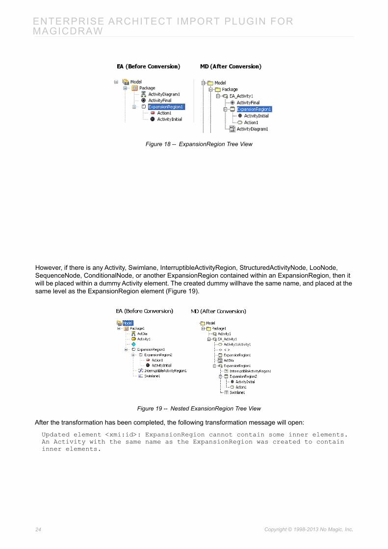
Most of the elements that are placed inside any ExpansionRegion elements in EA will stay in their original place (Figure 18).
23 Copyright © 1998-2013 No Magic, Inc..
ENTERPRISE ARCHITECT IMPORT PLUGIN FOR MAGICDRAW
Figure 18 -- ExpansionRegion Tree View
However, if there is any Activity, Swimlane, InterruptibleActivityRegion, StructuredActivityNode, LooNode, SequenceNode, ConditionalNode, or another ExpansionRegion contained within an ExpansionRegion, then it will be placed within a dummy Activity element. The created dummy willhave the same name, and placed at the same level as the ExpansionRegion element (Figure 19).
Figure 19 -- Nested ExansionRegion Tree View
After the transformation has been completed, the following transformation message will open:
Updated element <xmi:id>: ExpansionRegion cannot contain some inner elements. An Activity with the same name as the ExpansionRegion was created to contain inner elements.
24 Copyright © 1998-2013 No Magic, Inc..
ENTERPRISE ARCHITECT IMPORT PLUGIN FOR MAGICDRAW
6.2.9 InterruptibleActivityRegion
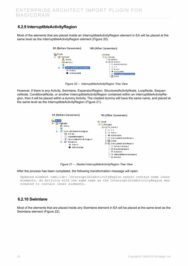
Most of the elements that are placed inside an InterruptibleActivityRegion element in EA will be placed at the same level as the InterruptibleActivityRegion element (Figure 20).
Figure 20 -- InterruptibleActivityRegion Tree View
However, if there is any Activity, Swimlane, ExpansionRegion, StructuredActivityNode, LoopNode, Sequen-ceNode, ConditionalNode, or another InterruptibleActivityRegion contained within an InterruptibleActivityRe-gion, then it will be placed within a dummy Activity. The created dummy will have the same name, and placed at the same level as the InterruptibleActivityRegion (Figure 21).
Figure 21 -- Nested InterruptibleActivityRegion Tree View
After the process has been completed, the following transformation message will open:
Updated element <xmi:id>: InterruptibleActivityRegion cannot contain some inner elements. An Activity with the same name as the InterruptibleActivityRegion was created to contain inner elements.
6.2.10 Swimlane
Most of the elements that are placed inside any Swimlane element in EA will be placed at the same level as the Swimlane element (Figure 22).
25 Copyright © 1998-2013 No Magic, Inc..

ENTERPRISE ARCHITECT IMPORT PLUGIN FOR MAGICDRAW
Figure 22 -- Swimlane Tree View
A dummy Activity will also be created to hold any other Swimlanes that it may contain. The dummy activity will have the same name and placed at the same level as the Swimlane.
If two or more Swimlanes are nested together, then every element (except Swimlane element) that is contained within either of them will be taken and placed at the same level as the Swimlane that tops the nested-Swim-lane-elements hierarchy (Figure 23).
Figure 23 -- Nested Swimlane Tree View
After the process has been completed, the following transformation message will open:
Updated element <xmi:id>: Swimlane cannot contain some inner elements. The XMI structure was fixed.
6.2.11 StructuredActivity
There are four elements that are classified as Structured Activity elements in EA:
(i) StructuredActivityNode element
(ii) LoopNode element
(iii) SequenceNode element
(iv) ConditionalNode element
Most of the elements that are placed inside any StructuredActivityNode, LoopNode, SequenceNode, or Condi-tionalNode elements in EA will stay in their original place (Figure 24).
26 Copyright © 1998-2013 No Magic, Inc..

ENTERPRISE ARCHITECT IMPORT PLUGIN FOR MAGICDRAW
Figure 24 -- StructuredActivityNode Tree View
However, if there is any Activity, Swimlane, InterruptibleActivityRegion, ExpansionRegion, or another Structure-dActivity contained within a StructuredActivity, then it will be placed within a dummy Activity. The created dummy will have the same name, and placed at the same level as the StructuredActivity (Figure 25).
Figure 25 -- Nested StructuredActivityNode Tree View
After the process has been completed, the following transformation messages will open depending on the Structured Activity elements that are involved:
• Updated element <xmi:id>: StructuredActivityNode cannot contain some inner elements. An Activity with the same name as the StructuredActivityNode was created to contain inner elements.
• Updated element <xmi:id>: ConditionalNode cannot contain some inner elements. An Activity with the same name as the ConditionalNode was created to contain inner elements.
• Updated element <xmi:id>: LoopNode cannot contain some inner elements. An Activity with the same name as the LoopNode was created to contain inner elements.
• Updated element <xmi:id>: SequenceNode cannot contain some inner elements. An Activity with the same name as the SequenceNode was created to contain inner elements.
27 Copyright © 1998-2013 No Magic, Inc..

ENTERPRISE ARCHITECT IMPORT PLUGIN FOR MAGICDRAW
6.2.12 InterruptFlow
EA InterruptFlows, in some cases, are ControlFlow lines, and their image will be displayed as that of the Inter-ruptFlow line in the Activity diagram. An InterruptFlow is not a ControlFlow line if the InterruptFlow line is drawned from one element, which is in an InterruptibleActivityRegion, to another outside that InterruptibleActiv-ityRegion. If there is such line in an XMI file, it will be imported as a ControlFlow line, and its image will be changed to that of the ControlFlow line.
However, if either end of the lines is any of the following elements, it will be transformed into an ObjectFlow line (Figure 26).
• InputPin element
• OutputPin element
• ObjectNode element
• CentralBufferNode element
• DataStoreNode element
Figure 26 -- InterruptFlow
28 Copyright © 1998-2013 No Magic, Inc..

ENTERPRISE ARCHITECT IMPORT PLUGIN FOR MAGICDRAW
6.2.13 ExpansionNode
An ExpansionNode is a Pin which can only be contained within an ExpansionRegion and will be imported like any other Pin elements. However, if an ExpansionNode in EA is created inside another element rather than an ExpansionRegion, that particular ExpansionNode will not be imported (Figure 27).
Figure 27 -- ExpansionNode
6.3 Sequence Diagram Elements
6.3.1 Lifelines
All of the EA Lifelines will be imported, but a part or port within a Lifeline will be transformed into a new separate Lifeline.
Gaps between Lifelines
The position and width of any Lifeline created in EA will not be imported. Every Lifeline will be given a fixed value and position in MagicDraw. MagicDraw will place the first Lifeline on the left-hand side of the diagram and the second Lifeline on the right-hand side next to the first one. The length of the gap between the Lifelines will
29 Copyright © 1998-2013 No Magic, Inc..

ENTERPRISE ARCHITECT IMPORT PLUGIN FOR MAGICDRAW
be fixed (Figure 28).
Figure 28 -- Gaps between Lifelines
Lifelines Arrangement
A Lifeline can be nested within another component such as a Part or Port. If this is the case, every component that is nested within the Lifeline and the Lifeline itself will be drawn separately in MagicDraw, and they will be arranged in order depending on the position of their Lifeline lines (Figure 29).
30 Copyright © 1998-2013 No Magic, Inc..

ENTERPRISE ARCHITECT IMPORT PLUGIN FOR MAGICDRAW
Figure 29 -- Lifelines Arrangement
Class, Part, and Port
Classes, Parts, and Ports have different characteristics from the others when they are represented as Lifelines. They will be bundled according to their relationships. One convenient way to create a Class, Part, or Port is through a Composite Structure diagram (Figure 30).
Figure 30 -- Class, Part, and Port
6.3.2 Gate
A Sequence Message whose tail is connected to a Gate (and the head connected to a Lifeline) in EA will be transformed into a Sequence Message with its tail connected to one of the boundary lines of the diagram in
31 Copyright © 1998-2013 No Magic, Inc..

ENTERPRISE ARCHITECT IMPORT PLUGIN FOR MAGICDRAW
which it is contained, and the Gate itself will be removed (Figure 31).
Figure 31 -- Gate
Once the Gate has been removed and the transformation process has been completed, the following transfor-mation message will open:Removed element <xmi:id>: uml:Gate.
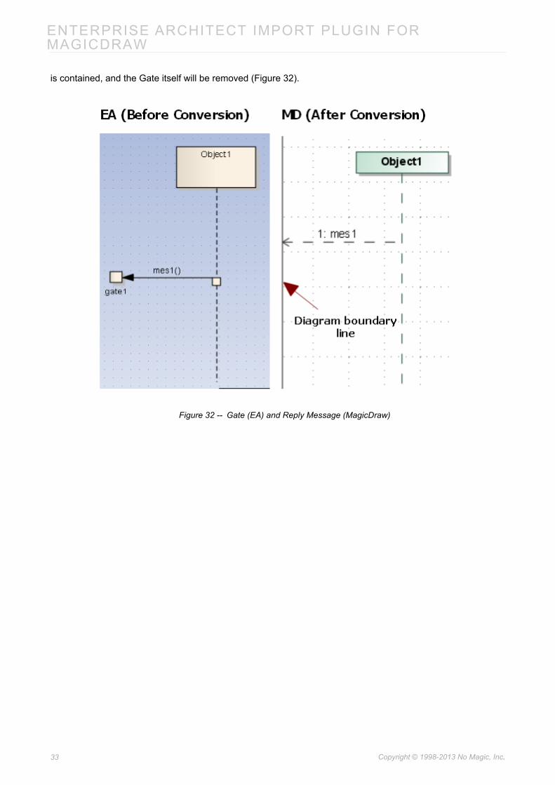
A Sequence Message whose head is connected to a Gate (and tail connected to a Lifeline line) in EA will be transformed into a Reply Message with its tail connected to one of the boundary lines of the diagram in which it
32 Copyright © 1998-2013 No Magic, Inc..
ENTERPRISE ARCHITECT IMPORT PLUGIN FOR MAGICDRAW
is contained, and the Gate itself will be removed (Figure 32).
Figure 32 -- Gate (EA) and Reply Message (MagicDraw)
33 Copyright © 1998-2013 No Magic, Inc..

ENTERPRISE ARCHITECT IMPORT PLUGIN FOR MAGICDRAW
The Diagonal Message and Reply Message will be connected to the nearest diagram boundary (Figure 33).
Figure 33 -- Gate (EA) and Direction of Diagonal Message (MagicDraw)
Anything else connected to a Gate, except the tail of a Sequence Message, will also be removed. For example, if the head of a Sequence Message is connected to a Gate, the Message will be removed. If the tail of a Mes-sage is connected to a Gate, but the head is connected to anything rather than a Lifeline line, the Message will be removed.
6.3.3 Endpoints
A Sequence Message whose head connected to an Endpoint and tail connected to a Lifeline line in EA, will be transformed into a Lost Message, and the Endpoint element itself will be removed. Once the process has been completed, the following transformation message will open:
Removed element <xmi:id>: EndPoint.
34 Copyright © 1998-2013 No Magic, Inc..

ENTERPRISE ARCHITECT IMPORT PLUGIN FOR MAGICDRAW
A Message whose head connected to a Lifeline line and tail connected to an Endpoint, will be transformed into a Found Message (Figure 34).
Figure 34 -- Endpoint
Anything else connected to an endpoint, except the head of a Sequence Message, will also be removed. For example, if the tail of a Sequence Message is connected to an endpoint, the Message will be removed.
If the head of a Message is connected to an endpoint, but the tail is connected to anything rather than a Lifeline line, the Message will be removed. Once the process has been completed, the following transformation mes-sage will open:
Removed element <xmi:id>: Invalid Message. Source and Target of the Message are not connected to any Lifeline.
6.3.4 Delete Messages
A Sequence Message whose property 'Lifecycle' is set to 'Delete' (that causes the Lifeline, which is being tar-geted by the Message, to end at some range after the point of contact), will be transformed into a Delete Mes-sage, and the Lifeline that is connected to its head will end at the point of contact, and all Messages will be removed after that point of contact of the Lifeline. MagicDraw will report the following transformation message once each process has been completed:
Removed element <xmi:id>: Message is under Delete Message.
35 Copyright © 1998-2013 No Magic, Inc..

ENTERPRISE ARCHITECT IMPORT PLUGIN FOR MAGICDRAW
Figure 35 -- Delete Message
Under certain circumstances a Lifeline, which is connected to the head of a Delete Message, does not end at the point of contact. Instead, an Activation will be created and started from the point of contact, and then the Lifeline will just end at the end of the Activation. However, that Activation should not interact with any Message (Figure 36).
Figure 36 -- Special Case of Delete Message
36 Copyright © 1998-2013 No Magic, Inc..

ENTERPRISE ARCHITECT IMPORT PLUGIN FOR MAGICDRAW
Under certain circumstances, an 'X' sign (normally will be drawn after a Delete Message) in EA will be drawn on a Lifeline line whose Lifeline is being pointed by a Create Message. If this is the case, the 'X' sign has no signif-icant meaning and can be ignored (Figure 37).
Figure 37 -- 'X' Sign
6.3.5 Branch Messages
If the Branch with previous Message option of a Sequence Message is enabled, the tail of the message will be connected to the tail of its previous Message on the same Lifeline line. The message will be called 'Branch Message' from that time on.
37 Copyright © 1998-2013 No Magic, Inc..

ENTERPRISE ARCHITECT IMPORT PLUGIN FOR MAGICDRAW
Every Branch Message in EA will be transformed into a normal Message in MagicDraw (Figure 38).
Figure 38 -- Branch Message
After the transformation process has been completed, the following transformation message will open:
Updated element <xmi:id>: Branch Message updated to regular Message.
6.3.6 Boundaries, Controls, and Entities
The Boundary, Control, and Entity elements in a Sequence diagram context in EA are Lifeline elements whose stereotype property type is set to 'Boundary', 'Control', or 'Entity'. They will be imported like any other normal Lifelines (Figure 39). However, an XMI exported from EA has a <<entity>> stereotype problem that causes the Lifeline with the <<entity>> stereotype applied unable to show the stereotype icon. You can solve this problem by placing an <<entity>> stereotype in EA_Profile.xml so that the converted model can use it
38 Copyright © 1998-2013 No Magic, Inc..

ENTERPRISE ARCHITECT IMPORT PLUGIN FOR MAGICDRAW
instead of the one from EA.
Figure 39 -- Boundary, Control, and Entity
6.3.7 Actors
An Actor element in the Sequence diagram context in EA is not a regular Lifeline element. It is a special Lifeline element whose property type is 'uml:Actor'. It will be transformed into a regular Actor and a Lifeline element will
39 Copyright © 1998-2013 No Magic, Inc..

ENTERPRISE ARCHITECT IMPORT PLUGIN FOR MAGICDRAW
be created to represent it. Figure 40 below shows an Actor element in the MagicDraw containment tree.
Figure 40 -- Actor
40 Copyright © 1998-2013 No Magic, Inc..

ENTERPRISE ARCHITECT IMPORT PLUGIN FOR MAGICDRAW
6.3.8 General Ordering
Every General Ordering element in EA will not be imported because MagicDraw does not support it in the cur-rent release (Figure 41).
Figure 41 -- General Ordering
After the transformation process has been completed, the following transformation message will open:
Updated element <xmi:id>: General Ordering will not be imported.
41 Copyright © 1998-2013 No Magic, Inc..

ENTERPRISE ARCHITECT IMPORT PLUGIN FOR MAGICDRAW
6.3.9 State Invariant
A State Invariant in EA will be transformed as it is (Figure 42). MagicDraw does not support State Invariants in the current release.
Figure 42 -- State Invariant
6.3.10 Continuation
Continuations from EA can be imported to MagicDraw. They are viewable in the containment tree in Magic-Draw, but without a picture displayed in the diagram (Figure 43). MagicDraw does not support Continuations in the current release.
Figure 43 -- Continuation
After the transformation process has been completed, the following transformation message will open:
Updated element <xmi:id>: Continuation will not be displayed.
42 Copyright © 1998-2013 No Magic, Inc..

ENTERPRISE ARCHITECT IMPORT PLUGIN FOR MAGICDRAW
6.3.11 Diagonal Message
A Diagonal Message is a Message whose destination's height is adjustable (Figure 44). A diagonal Message may change Activations.
Figure 44 -- Diagonal Message
43 Copyright © 1998-2013 No Magic, Inc..

ENTERPRISE ARCHITECT IMPORT PLUGIN FOR MAGICDRAW
To create a Diagonal Message in EA, you need to specify the Timing Details property of the Message and add a numeric value to the Duration Constraint input field (Figure 45).
Figure 45 -- Creating a Diagonal Message
6.3.12 Synchronous Message Behavior
The placement of Synchronous Messages in EA will affect the way Activations are created.
Order
A Message in EA has a 'Sequence Number' that indicates the order of the message in the diagram. This infor-mation can be found in the exported XMI file and knowing it helps predicting the way how Activations will be created. The order starts from the top and goes downward, so the first Message in the diagram is the one that
44 Copyright © 1998-2013 No Magic, Inc..

ENTERPRISE ARCHITECT IMPORT PLUGIN FOR MAGICDRAW
is drawn at the top of the diagram and it will have its Sequence Number set to '1' (Figure 46).
Figure 46 -- Message Sequence Number
Process
Generally, in EA, any two Synchronous Messages will be in the same process if they meet the following condi-tions (Figure 47):
• Both of their tails placed on the same Lifeline.
45 Copyright © 1998-2013 No Magic, Inc..

ENTERPRISE ARCHITECT IMPORT PLUGIN FOR MAGICDRAW
• The head of the upper Message and the tail of the lower Message are on the same Lifeline.
Figure 47 -- Process
46 Copyright © 1998-2013 No Magic, Inc..

ENTERPRISE ARCHITECT IMPORT PLUGIN FOR MAGICDRAW
Activation Level
The Activation Level starts from level 0 and will be increased in increments of 1 as an ongoing process receives a Message that is not a Return Message (Reply Message in MagicDraw) (Figure 48).
Figure 48 -- Activation Level
6.3.13 Asynchronous Message Behavior
If a Message is an Asynchronous Message in EA, then its source Activation will end if there is no other Mes-sage in the same group that has a higher Sequence Number, and its source will be attached to the same Life-
47 Copyright © 1998-2013 No Magic, Inc..

ENTERPRISE ARCHITECT IMPORT PLUGIN FOR MAGICDRAW
line (Figure 49).
Figure 49 -- Asynchronous Message
6.3.14 Return Message Behavior
A Return Message in EA is called a Reply Message in MagicDraw. One of its characteristics is that when it is pointed to an Activation, it will not create an Activation at the top of the existing Activation (unlike other normal Synchronous Messages) (Figure 50).
Figure 50 -- Return Message
48 Copyright © 1998-2013 No Magic, Inc..

ENTERPRISE ARCHITECT IMPORT PLUGIN FOR MAGICDRAW
6.3.15 Activation Options
You can control how Activations behave at some level through the Message options, which you can access by right-clicking any Message, and then select the Activations option. However, MagicDraw does not support Activation Options in the current release.
Figure 51 -- Activation Options
6.4 Communication Diagram Elements
6.4.1 Object, Boundary, Entity, and Control
All of the Object, Boundary, Entity, Control elements in EA are InstanceSpecifications. After conversion, their UML element types will remain, and a Lifeline and an OwnedAttribute element will be created to represent each of them in the Communication diagram in which they are in.
Figure 52 -- Object, Boundary, Entity, and Control (Diagram View)
49 Copyright © 1998-2013 No Magic, Inc..

ENTERPRISE ARCHITECT IMPORT PLUGIN FOR MAGICDRAW
Figure 53 -- Object, Boundary, Entity, and Control (Containment Tree)
Other elements that can be drawn in a Communication diagram will be handled in a similar manner.
6.4.2 Exception Elements
Some of the elements that can be drawn in a Communication diagram using EA are not supported by Magic-Draw, consequently, their displaying parts will not be imported. Such elements are Package, Activity, Action, DiagramFrame, State, Interaction, ExceptionHandler, CentralBufferNode, InterruptibleActivityRegion, MergeNode, Trigger, ExpansionRegion, and InteractionFragment.
50 Copyright © 1998-2013 No Magic, Inc..

ENTERPRISE ARCHITECT IMPORT PLUGIN FOR MAGICDRAW
Figure 54 -- Exception Elements
6.4.3 Realization and Nesting
The Realization's element type in EA is 'uml:Realization' and the Nesting's element type in EA is exported in XMI as 'uml:Dependency'.
The Realization and Nesting lines in EA are not supported in the Communication diagram; therefore, only their model data, not the displaying parts, that will be imported.
51 Copyright © 1998-2013 No Magic, Inc..

ENTERPRISE ARCHITECT IMPORT PLUGIN FOR MAGICDRAW
Figure 55 -- Realization and Nesting
6.4.4 Association
Every Association relationship that is drawn in a Communication diagram in EA will have a Connector line cre-ated for each of them, and the elements that are attached to the Association line's both ends will have a Lifeline element created to represent each of them. So, the Association lines and the elements that are attached to them will not be removed, but the elements that will be shown in the MagicDraw's diagram frame will be those of the Lifeline elements and the Connector lines that are created to represent them (Figure 56).
52 Copyright © 1998-2013 No Magic, Inc..

ENTERPRISE ARCHITECT IMPORT PLUGIN FOR MAGICDRAW
Figure 56 -- Association
53 Copyright © 1998-2013 No Magic, Inc..

ENTERPRISE ARCHITECT IMPORT PLUGIN FOR MAGICDRAW
If an Association line is connected to the InstanceSpecification elements, its data will be removed. If an Associ-ation line is linked between two InstanceSpecification elements, it will be transformed into an InstanceSpecifi-cation element. This is one of the constraints that belongs to the Communication diagram.
Figure 57 -- Association Line between InstanceSpecifications
6.4.5 Message
Messages can be created on Connectors and will be imported to MagicDraw (Figure 58).
54 Copyright © 1998-2013 No Magic, Inc..

ENTERPRISE ARCHITECT IMPORT PLUGIN FOR MAGICDRAW
Figure 58 -- Message
6.4.6 Operations
An InstanceSpecification cannot contain Operation elements. If the XMI file from EA has some InstanceSpecifi-cation elements that contain Operation elements, those Operations will be removed (Figure 59).
55 Copyright © 1998-2013 No Magic, Inc..

ENTERPRISE ARCHITECT IMPORT PLUGIN FOR MAGICDRAW
Figure 59 -- Operations
6.5 State Machine Diagram Elements
6.5.1 StateMachine
After conversion, a dummy StateMachine element will be created. The dummy StateMachine is either created by XMI exporter from EA or by EA Import plugin. A StateMachine diagram will be placed inside the dummy StateMachine and a dummy Region element will be created to contain all of the StateMachine elements (Fig-ure 60).
Figure 60 -- Dummy StateMachine Element and Dummy Region Element
56 Copyright © 1998-2013 No Magic, Inc..

ENTERPRISE ARCHITECT IMPORT PLUGIN FOR MAGICDRAW
6.5.2 State
State Containing Other Elements
A State element that contains other elements will be transformed to a Composite State and all of the contained elements will be placed inside the Region element of the State element (Figure 61).
Figure 61 -- State Containing Other Elements
State Containing StateMachine
If a State element contains a StateMachine element, the StateMachine element will be brought out and placed at the same level of the Region element of the State element.
57 Copyright © 1998-2013 No Magic, Inc..

ENTERPRISE ARCHITECT IMPORT PLUGIN FOR MAGICDRAW
Figure 62 -- State Containing StateMachine
State Containing Attribute and Operation
If a State element contains Attribute and Operation elements. The Attribute and Operation elements will be removed both from the Diagram view and Containment tree (Figure 63).
58 Copyright © 1998-2013 No Magic, Inc..

ENTERPRISE ARCHITECT IMPORT PLUGIN FOR MAGICDRAW
Figure 63 -- State Containing Attribute and Operation
The following transformation messages will open:
• Removed element <xmi:id>: State cannot contain Attribute.
• Removed element <xmi:id>: State cannot contain Operation.
State Containing Diagram Element
If a diagram element is placed inside a State element, it will be removed (Figure 64).
59 Copyright © 1998-2013 No Magic, Inc..

ENTERPRISE ARCHITECT IMPORT PLUGIN FOR MAGICDRAW
Figure 64 -- State Containing Diagram Element
The following transformation message will open:
Removed element <xmi:id>: State cannot contain diagram element.
6.5.3 StateMachine Placed on a Diagram
If a StateMachine element is drawn in a StateMachine diagram, an additional SubMachineState will be created to represent the StateMachine (Figure 65).
NOTE A SubMachine State is a State whose SubMachine property is set to a StateMachine.
60 Copyright © 1998-2013 No Magic, Inc..

ENTERPRISE ARCHITECT IMPORT PLUGIN FOR MAGICDRAW
Figure 65 -- StateMachine Represented by a SubMachine State
6.5.4 Object
An Object element placed in a State Machine diagram will be removed from the Diagram view, however, its data will be preserved in the Containment tree as an InstanceSpecification (Figure 66).
61 Copyright © 1998-2013 No Magic, Inc..

ENTERPRISE ARCHITECT IMPORT PLUGIN FOR MAGICDRAW
Figure 66 -- Object
The following transformation message will open:
Removed view <xmi:id>: The view represents element that does not support in State Machine Diagram.
Object Containing State Machine Element
In EA, an Object element can contain a State Machine element. After being imported to MagicDraw, the State Machine element that is placed inside an Object element will be removed both from the Diagram view and Con-tainment tree, however, the Object element data will be preserved. All of the Object element data will be placed at the closest owner package of the Object element (Figure 67).
62 Copyright © 1998-2013 No Magic, Inc..

ENTERPRISE ARCHITECT IMPORT PLUGIN FOR MAGICDRAW
Figure 67 -- Object Containing State Machine Element
The following transformation message will open:
Removed element <xmi:id>: Invalid element. Instancespecification can not contain element from State Machine.
6.5.5 Synch
A Synch element will be transformed to a Junction element (Figure 68).
63 Copyright © 1998-2013 No Magic, Inc..

ENTERPRISE ARCHITECT IMPORT PLUGIN FOR MAGICDRAW
Figure 68 -- Synch
The following transformation message will open:
Updated element <xmi:id>: Synch updated to Junction.
6.5.6 EntryPoint / ExitPoint
An Entry or Exit point, which is placed inside a State (or StateMachine) element, will be placed outside a Region element of its parent element in the Containment tree and relocated to the nearest boundary of its par-ent element in the Diagram view (Figure 69).
64 Copyright © 1998-2013 No Magic, Inc..

ENTERPRISE ARCHITECT IMPORT PLUGIN FOR MAGICDRAW
Figure 69 -- Entry/Exit Point
6.5.7 Object Flow Connecting State Machine Elements
An Object Flow connecting the elements in a State Machine will be removed both from the Diagram view and Containment tree (Figure 70).
Figure 70 -- ObjectFlow Connecting State Machine Elements
The following transformation message will open:
Removed element <xmi:id>: Invalid ObjectFlow. Source or Target of the ObjectFlow are connected to element from State Machine.
65 Copyright © 1998-2013 No Magic, Inc..

ENTERPRISE ARCHITECT IMPORT PLUGIN FOR MAGICDRAW
6.5.8 Information Flow Connecting State Machine Elements
An Information Flow connecting the elements in a State Machine will be removed from the Diagram view, how-ever, its data will be preserved.
Figure 71 -- Information Flow, Trace, and Dependency
The following transformation message will open:
Removed element <xmi:id>: The view represents element that does not support in State Machine Diagram.
66 Copyright © 1998-2013 No Magic, Inc..

ENTERPRISE ARCHITECT IMPORT PLUGIN FOR MAGICDRAW
6.5.9 Trigger
If there is a Trigger element that is not related to any Transition line, a dummy StateMachine will be created to hold the Trigger element. The dummy StateMachine will be named after the parent package name concatenat-ing with 'trigger'.
In the case of a Trigger element that is related to Transition, the data of the Trigger element will be placed inside its parent Transition. Each Trigger element will be given an event type, which is represented by an Event element. After conversion, the Event will be placed at the closest owner package of the Event.
Figure 72 -- Trigger
6.5.10 Self Transition
Most of the elements in a StateMachine diagram can have a self transition, except for the Initial, Final, and His-tory elements. The self transition in these three elements will be removed from the Diagram view, but the data of the self transition will be preserved in the Containment tree.
67 Copyright © 1998-2013 No Magic, Inc..

ENTERPRISE ARCHITECT IMPORT PLUGIN FOR MAGICDRAW
Figure 73 -- Self Transition
The following transformation messages will open:
• Removed view <xmi:id>: Self Transition does not support for Initial.
• Removed view <xmi:id>: Self Transition does not support for Final.
• Removed view <xmi:id>: Self Transition does not support for History.
6.5.11 Removed Element
An element, which is not the element of a State Machine diagram, for example, Class, Actor, Usecase, or Action, and drawn in the State Machine diagram, will be removed from the Diagram view. However, its data will be preserved in the Containment tree.
Figure 74 -- Removed Element
If an element, which is not the element of a State Machine diagram, has a child element and it is drawn in the State Machine diagram, the element will be removed from the Diagram view, however, its data will be pre-served in the Containment tree.
68 Copyright © 1998-2013 No Magic, Inc..

ENTERPRISE ARCHITECT IMPORT PLUGIN FOR MAGICDRAW
Figure 75 -- Removed Element with a Child Element
The following transformation message will open:
Removed view <xmi:id>:The view represents element that does not support in State Machine Diagram.
6.6 Composite Structure Diagrams
This section will describe some additional EA specific Composite Structure diagram information.
6.6.1 Import Elements
One way EA is different than MagicDraw is in how the Composite Structure diagram's content elements are designed. Table 11 below shows the differences by focusing on the EA’s elements and how they will be trans-formed or converted into the format that MagicDraw can correctly load and display. The element names shown in the table are the same as those in both EA and MD 's GUI. The contents in the bracket ([…]) are the XMI ele-ment type references.
69 Copyright © 1998-2013 No Magic, Inc..

ENTERPRISE ARCHITECT IMPORT PLUGIN FOR MAGICDRAW
Table 11 -- Differences between EA and MagicDraw
6.6.2 Conversion Details
Dummy Class
In MagicDraw, the Composite Structure diagram needs a Context element to contain itself, whereas in EA, there is no Context element. After conversion, a dummy Class element will be created to represent the Context element of Composite Structure diagram.
A dummy Class will be named after the closest owner package of the Composite Structure diagram. The Com-posite Structure diagram and all of the Composite Structure elements will be placed inside the dummy Class element.
Figure 76 -- Dummy Class
Class
The Class element data will be normally copied even if the Class element is drawn in a Composite Structure diagram. A Property element will be created to represent the Class element. The Property element will be named after the Class element.
Enterprise Architect MagicDraw
Interaction
Class [uml:Class] Class [uml:Class]
Interface [uml:Interface] Interface [uml:Interface]
Part [uml:Class]Part [uml:Property]
Part [uml:Property]
Port [uml:Port] Port [uml:Port]
Collaboration [uml:Collaboration] Collaboration Use [uml:Collaboration]
Expose Interface [not exist]
Connector [element type is not exist] Connector [uml:Connector]
Assembly [element type is not exist]
Delegate [element type is not exist] Connector [uml:Connector]
Role Binding [uml:Dependency] Role Binding [uml:Dependency]
Represents [uml:Dependency] Dependency [uml:Dependency]
Occurrence [uml:Dependency] Dependency [uml:Dependency]
70 Copyright © 1998-2013 No Magic, Inc..

ENTERPRISE ARCHITECT IMPORT PLUGIN FOR MAGICDRAW
Figure 77 -- Property Representing a Class Element
Class with Attributes and Operations
The Class view in EA will be converted to a Part in MagicDraw; therefore, attributes and operations will not be shown in the Composite Structure diagram.
Figure 78 -- Part Element after Conversion
71 Copyright © 1998-2013 No Magic, Inc..

ENTERPRISE ARCHITECT IMPORT PLUGIN FOR MAGICDRAW
Interface
The Interface element data will be normally copied even if the Interface element is drawn in a Composite Struc-ture diagram. A Property element will be created to represent the Interface element. The Property element will be named after the Interface element.
Figure 79 -- Property Representing Interface Element
Part
There are two types of Parts: (i) Part with port and (ii) Part that sets type to other elements.
(i) Part with Port
If you assign the type of a Part element to a Class, Component, or Node, the Part element can have a Port (see () Port for more information).
In the case of a Part is not nested to any element, the Part element will be exported from EA as a Class; there-fore, this Part element can have a Port.
72 Copyright © 1998-2013 No Magic, Inc..

ENTERPRISE ARCHITECT IMPORT PLUGIN FOR MAGICDRAW
Figure 80 -- Part that does not Nest Element(s) with Posts
In the case of a Part is nested to an element and the type is not set, then the Part type will be used to set type to a dummy Class. This particular Part can have a Port.
A dummy Class will be created at the same level of the Part element that sets type to it. The dummy Class will be named after the Part concatenating with '_type'.
Figure 81 -- Part that Nests Element(s) with Post
(ii) Part that sets type to other elements
The type of Part can be set to another element, for example, a Class, Actor, Component, or Usecase by right-clicking the Part element and select Advanced > Set Property Type > Select Property Type (Figure 82).
73 Copyright © 1998-2013 No Magic, Inc..

ENTERPRISE ARCHITECT IMPORT PLUGIN FOR MAGICDRAW
Figure 82 -- Setting Part Type
If the Part type is set to a type that cannot be the owner of a port, the port will be removed.
In MagicDraw, the Property element data cannot have any elements, whereas in EA, it can have any elementst; therefore, if you draw a Part element and it has an element inside it, that particular element will be relocated to an element, which is the Part type.
In the case of a Part is not nested to any element, the Part element will be exported from EA as a Class; there-fore, the element inside the Part will not be relocated. If that particular Part assigns a type to other elements, its type will always be set to Class.
Figure 83 -- Part that Sets Type to Other Elements
74 Copyright © 1998-2013 No Magic, Inc..

ENTERPRISE ARCHITECT IMPORT PLUGIN FOR MAGICDRAW
In the case of a Nested Part whose type is set to another element, for example, a Class, Actor, or Usecase, and this Part contains Nested elements, all of the Nested elements of the Part will be relocated to the element that is the type of this Part.
Figure 84 -- Part that Sets Type to Other Elements has Nested Element Inside Itself
Port
In MagicDraw, a Property element that can have a Port is the Property that sets type to a Class, Component, or Node, and other elements cannot have a Port, whereas in EA, most of the elements can have a Port.
If a Port is created with an element that is not a Class, Component or Node, the Port will be removed from the diagram view, however, its data will be preserved.
75 Copyright © 1998-2013 No Magic, Inc..

ENTERPRISE ARCHITECT IMPORT PLUGIN FOR MAGICDRAW
Figure 85 -- Only Class, Component, and Node Can Have a Port
The following transformation message will open:
Removed view <xmi:id>: Invalid Port. Port can be added to Part that its type is set to Class, Component and Node only.
(i) Port whose type is set to other elements
You can set the type of Port element to another element (a Class, Actor, Component, or Usecase) by right-clicking the Port element and select Advanced > Set Property Type > Select Property Type (Figure 86).
Figure 86 -- Setting Port Type
(ii) Port whose type is set to another element and containing Expose Interfaces
76 Copyright © 1998-2013 No Magic, Inc..

ENTERPRISE ARCHITECT IMPORT PLUGIN FOR MAGICDRAW
If an Expose Interface is created on a Port and the Port type is set to another element, the Expose Interface data will be relocated to the Port's type element. For example, if the Port1 type is set to Actor, after conversion, an Interface Realization (the Expose Interface data) will be placed inside the Actor.
Figure 87 -- Port that Sets Type to Other Element Contains Expose Interface
Collaboration
The Collaboration element data and its nested data will be normally copied, however, if the Collaboration ele-ment is drawn in a Composite Structure diagram, a Collaboration use element will be created to represent the Collaboration element. The Collaboration use element will be named after the Collaboration element.
Figure 88 -- Collaboration Use
77 Copyright © 1998-2013 No Magic, Inc..

ENTERPRISE ARCHITECT IMPORT PLUGIN FOR MAGICDRAW
Collaboration containing other elements
A Collaboration can contain only Property, Activity, State Machine, and Interaction. Elements other than these will be removed. If any element is drawn inside the Collaboration, it will be removed from the diagram view (Fig-ure 89).
Figure 89 -- Collaboration Containing Other Elements
The following transformation messages will open:
• Removed element <xmi:id>: Invalid Element. Collaboration can contain Property, Activity, State Machine and Interaction only.
• Removed view <xmi:id>: Invalid Element view. Collaboration cannot be contained in any element view.
Expose Interface
Expose Interfaces are the Provided and Required interfaces in MagicDraw.
In MagicDraw, you can draw a Provided Interface or Required Interface in a Port only and set the type of the Port to another element (an Actor, Usecase, or Class). You can create that particular Port on a Part element whose type is set to a Class, Component, or Node only.
(i) Expose Interface with Port
If you draw an Expose Interface in a Port and the Port does not assign a type to any elements, that particular Port will be used to set type to a Dummy Class. The Dummy Class will be created and named after the Port concatenating with '_type'. The Interface element will be moved to the same level of the Port.
78 Copyright © 1998-2013 No Magic, Inc..

ENTERPRISE ARCHITECT IMPORT PLUGIN FOR MAGICDRAW
Figure 90 -- Expose Interface with Port
If an Expose Interface is created on a Port and the type of the Port is set to another element, the Expose Inter-face data will be relocated to the Port's type element (see (ii) Port whose type is set to another element and containing Expose Interfaces for more information).
In MagicDraw, there are some elements that can be used as a Port type. The element can have either a Pro-vided Interface or Required Interface, or both.
The following is a list of the Port's type elements with specific conditions:
• Interfaces can only have a Provided Interface.
• Artifacts cannot have a Provided Interface.
• Information Items cannot have a Provided Interface.
• Signals cannot have a Provided Interface.
• Components always have both Provided and Required Interfaces.
• The other elements can have both Provided and Required Interfaces.
• After conversion, if the type of a Port is set to an Interface and the Port has an Expose Interface, only the Provided Interface will be shown and the Interface Realization data will be removed.
• Artifacts, Information Items, and Signals cannot hold Interface Realization. If the type of a Port is set to one of them, the Provided Interface will be removed. However, this does not affect the Required Interface.
• If the type of a Port is set to a Component and the Port has an Expose Interface, it will always show both the Provided and Required Interfaces.
79 Copyright © 1998-2013 No Magic, Inc..

ENTERPRISE ARCHITECT IMPORT PLUGIN FOR MAGICDRAW
Figure 91 -- Port’s Type Element with Specific Conditions
The following transformation message will open:
Updated element <xmi:id>: Provided Interface conflicts with Port type. The Port type is updated to an owner of Interface Realization.
If an Expose Interface is created with an element that is not a Port, the element will be removed both from the Containment tree and diagram view (Figure 92).
Figure 92 -- Expose Interface with Element that is not Port
The following transformation message will open:
80 Copyright © 1998-2013 No Magic, Inc..

ENTERPRISE ARCHITECT IMPORT PLUGIN FOR MAGICDRAW
Removed element <xmi:id>: Invalid Element. Expose Interface can be added to Port only.
(ii) Expose Interface with relationship
In MagicDraw, the Provided and Required Interfaces cannot be connected with any relationship as is shown in Figure 93. If there is any relationship connecting to the Expose Interface, it will be removed both from the Con-tainment tree and diagram view.
Figure 93 -- Expose Interface with Lines
The following transformation message will open:
Removed element <xmi:id>: Invalid Element. Expose Interface cannot be connected with the element.
Package
In MagicDraw, a Package cannot be drawn in a Composite Structure diagram. If it is drawn in EA, it will be removed from the diagram once it has been converted to MagicDraw.
Figure 94 -- Package
Assembly
In MagicDraw, there is no Assembly line. It will be updated to a Connector.
81 Copyright © 1998-2013 No Magic, Inc..

ENTERPRISE ARCHITECT IMPORT PLUGIN FOR MAGICDRAW
Figure 95 -- Updating the Assembly Line to the Connector Line
The following transformation message will open:
Updated element <xmi:id>: Assembly updated to Connector.
Dependency
There are many relationships that EA exporter exports to Dependency as the following elements:
• Delegate
• Role Binding
• Represents
• Occurrence
• Nest
• Derive
• Import
• Instantiate
• Usage
• Realize
• Trace
The above relationships will be shown in the diagram view as Dependencies with stereotype.
Removed Relationships
If an Association, Direct Association, Aggregation, Composition, Generalization, or Specialization is created in a Composite Structure diagram, it will be removed from the diagram view, but, its data will be preserved (Fig-ure 96).
82 Copyright © 1998-2013 No Magic, Inc..

ENTERPRISE ARCHITECT IMPORT PLUGIN FOR MAGICDRAW
Figure 96 -- Removing Lines
The following transformation messages will open:
• Removed view <xmi:id>: Association cannot be shown in Composite Structure diagram.
• Removed view <xmi:id>: Direct Association cannot be shown in Composite Structure diagram.
• Removed view <xmi:id>: Aggregation cannot be shown in Composite Structure diagram.
• Removed view <xmi:id>: Composition cannot be shown in Composite Structure diagram.
• Removed view <xmi:id>: Generalization cannot be shown in Composite Structure diagram.
6.6.3 Transformation Report
A report containing the conflicts solved during transformation and other transformation information such as spe-cial mapping and removal of some irrelevant data, are required to be provided to the users.
The following is a list of the transformation messages:
• Removed view <xmi:id>: Invalid Port. Port can be added to Part that set type to Class, Component, and Node only.
• Removed element <xmi:id>: Invalid Element. Collaboration can contain Property, Activity, State Machine, and Interaction only.
83 Copyright © 1998-2013 No Magic, Inc..

ENTERPRISE ARCHITECT IMPORT PLUGIN FOR MAGICDRAW
• Removed view <xmi:id>: Collaboration cannot be contained in any element view.
• Removed view <xmi:id>: UseCase cannot be contained in any element view.
• Removed element <xmi:id>: Invalid Element. Expose Interface can be added to Port only.
• Removed element <xmi:id>: Invalid Element. Expose Interface cannot be connected with the element.
• Updated element <xmi:id>: Assembly updated to Connector.
• Updated element <xmi:id>: Provided Interface conflicts with Port type. The Port type is updated to an owner of Interface Realization.
• Removed view <xmi:id>: Association cannot be shown in Composite Structure diagram.
• Removed view <xmi:id>: Direct Association cannot be shown in Composite Structure diagram.
• Removed view <xmi:id>: Aggregation cannot be shown in Composite Structure diagram.
• Removed view <xmi:id>: Composition cannot be shown in Composite Structure diagram.
• Removed view <xmi:id>: Generalization cannot be shown in Composite Structure diagram.
6.7 Interaction Overview Diagrams
The following sections will describe some additional EA specific Interaction Overview diagram information.
6.7.1 Conversion Details
Interaction Overview Diagram
An Interaction Overview diagram is one of the four types of Interaction diagrams (the other three are Timing, Sequence, and Communication diagrams).
An Interaction Overview diagram, just like an Activity diagram, visualize a sequence of activities. Most of the notation elements for Interaction Overview diagrams are the same as those for Activity diagrams such as initial, decision, fork, join, and final nodes. Two new elements in the interaction overview diagrams are Interaction Occurrences and Interaction elements.
84 Copyright © 1998-2013 No Magic, Inc..

ENTERPRISE ARCHITECT IMPORT PLUGIN FOR MAGICDRAW
Figure 97 -- Interaction Overview Diagram
After conversion, the Interaction Overview diagram will be placed within an Activity element (Figure 98).
Figure 98 -- Interaction Overview Diagram Placement
Interaction Element
Interaction elements are elements that display an inline Interaction diagram (Interaction Overview, Timing, Sequence, or Communication diagram).
In EA, Interaction elements can be created to display other diagrams rather than those classified as Interaction diagrams (Figure 99).
85 Copyright © 1998-2013 No Magic, Inc..

ENTERPRISE ARCHITECT IMPORT PLUGIN FOR MAGICDRAW
Figure 99 -- Interaction Element
Interaction elements will not be imported to MagicDraw.
Figure 100 -- Interaction Element in Interaction Overview Diagram
86 Copyright © 1998-2013 No Magic, Inc..
ENTERPRISE ARCHITECT IMPORT PLUGIN FOR MAGICDRAW
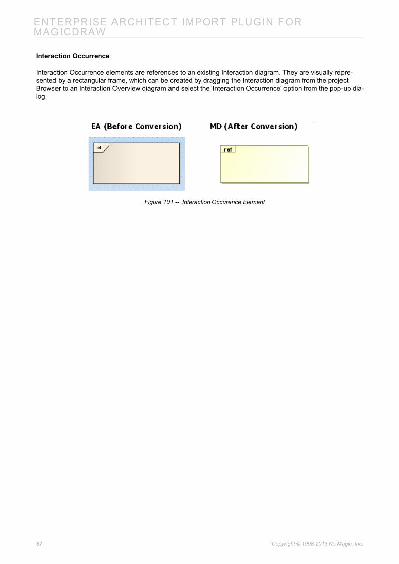
Interaction Occurrence
Interaction Occurrence elements are references to an existing Interaction diagram. They are visually repre-sented by a rectangular frame, which can be created by dragging the Interaction diagram from the project Browser to an Interaction Overview diagram and select the 'Interaction Occurrence' option from the pop-up dia-log.
Figure 101 -- Interaction Occurence Element
87 Copyright © 1998-2013 No Magic, Inc..

ENTERPRISE ARCHITECT IMPORT PLUGIN FOR MAGICDRAW
7. Known Limitations and Constraints Table 12 shows the conversion limitations and constraints in EA exported XMI and EA Import Plugin.
Table 12 -- Limitations and Costraints
No. Constraint name Description
1 N-ary Association Due to the difference between the EA exported XMI and MagicDraw XMI, the view of N-ary association will not be imported.
2 Diagram Legend MagicDraw does not have a similar element. Diagram legends will not be imported.
3 Diagram Note The element most similar to Diagram Note is the MagicDraw diagram information table (Option > Show diagram info). However, it will be mapped to the Option > show diagram details, in EA. So Diagram Notes will not be imported to MagicDraw.
4 Text size The size of text displayed in EA and MagicDraw may vary. The text size in EA is mostly bigger.
5 Word wrap Due to size constraints in text displayed in element blocks, the result of word wrap in EA and MagicDraw is likely to be different.
6 Contact point between element and link
The position of both ends of a link element cannot be mapped to Magic-Draw because the last segments of the link element in MagicDraw always point to the center of connected elements.
7 Display alternative image
In EA, you can display an element in a diagram by using an alternative image. MagicDraw will not import that particular image. A default shape will be used instead.
8 Link label position A Link element such as an association has many text labels, for example, multiplicity and role name labels. MagicDraw will not import the position of these labels. A default position will be used instead.
9 Pin position A pin position in MagicDraw may have been slightly moved from its origi-nal position in EA. Especially if the pin is placed at the corner of its con-taining element, it will be shifted a little away from the corner (mostly in a clockwise direction).
10 Nested CallBehavior-Action
A CallBehaviorAction element nested with another CallBehaviorAction ele-ment. The outermost part of the element will remain, the other will be removed.
11 DataStoreNode inner element
A DataStoreNode element that contains Activity-Diagram-related-ele-ments. Every element inside that particular DataStoreNode element will be removed, only the DataStoreNode element will remain.
12 Object inner element An Object element that contains Activity-Diagram-related-elements. Every element inside that particular Object element will be removed, only the Object element will remain.
13 Lifeline position A position of Lifeline in MagicDraw will not correspond to the original posi-tion in EA. The position is fixed.
14 Diagonal Sequence Message
MagicDraw does not support Diagonal Sequence Messages.
15 Sequence Activation Options
MagicDraw does not support manipulating Sequence Activation through Sequence Activation Options.
88 Copyright © 1998-2013 No Magic, Inc..

ENTERPRISE ARCHITECT IMPORT PLUGIN FOR MAGICDRAW
16 State contains dia-gram
If a diagram element placed inside State element. It will be removed.
17 Region in Orthogo-nal State
EA exported XMI contains incorrect information when: • more than one regions have identical name. • region was created and then removed before exported to XMI.This will result in an unexpected result after importing it into MagicDraw.
18 Assembly Relation-ship in Composite Structure diagram
Assembly relationships in EA are exported to XMI as Connectors.Conse-quently, they will be imported to MagicDraw as Connectors.
19 Interaction elements as diagram frame
MagicDraw does not import Interaction element displayed as diagram frame in Interaction Overview diagram.
20 Message timing details
Duration Observation, and Timing Observation do not be imported to MagicDraw.
21 Concurrent State Regions in StateMa-chine
Adding and removing multiple Concurrent State Regions to and from StateMachine in EA can cause the EA XMI to be incorrectly exported. If the EA exported XMI is in this state, the result of the StateMachine imported to MagicDraw cannot be determined.The same problem also occures if there are multiple Concurrent State Regions with the same name.
22 Combined Fragment Adding and removing multiple Interaction Operands to and from Combined Fragment in EA can cause the EA XMI to be incorrectly exported. The problem can be fixed by impoting the EA XMI back to a new project in EA and export it back before importing it to MagicDraw.
23 Problem occur during conversion of Sequence diagram.
Importing EA XMI to MagicDraw sometime results in the message saying that “Problem occur during conversion of Sequence diagram”. If this problem occurs, Please try to import the XMI back to a new project in EA and export it back again before importing it to MagicDraw.
No. Constraint name Description
89 Copyright © 1998-2013 No Magic, Inc..