enterprise application development using uml, java ... · 3 ts-641, enterprise application...
TRANSCRIPT

TS-641, Enterprise Application Development Using UML, Java, and XML1
Enterprise Application Development Using UML, Java™ Technology and XML
Will HoweryCTOPassage Software LLC

TS-641, Enterprise Application Development Using UML, Java, and XML2
Introduction
• Effective management and modeling of enterprise applications
• Web and business-to-business applications• Messaging environments
– Loosely coupled– Asynchronous– Fault tolerant
• Java technology provides the descriptive language • XML provides the data representation • UML provides the notational language• Manage complexity for deploying n-tier
enterprise applications

TS-641, Enterprise Application Development Using UML, Java, and XML3
Overview
• A process and examples for building UML applications with XML messages through multiple distributed server containers
• Illustrate a complete UML design for n-tier application web development
• Implement a web based logon and user profile application
• Utilizing – UML – Java technology – XML DTD/schema definitions

TS-641, Enterprise Application Development Using UML, Java, and XML4
Tools
• Examples presented in UML using Rational Rose with UML Factory
• The examples will be implemented with JAR components that can be deployed into multiple configurations
• UML Factory will generate, deploy, and animate the examples through the UML diagrams

TS-641, Enterprise Application Development Using UML, Java, and XML5
Technologies
• UML: – Unified Modeling Language will describe the
static and dynamic behavior for applications• XML:
– Extensible Markup Language describes document information for building pages and carrying messages through the application tiers
• JSP™ components:– JavaServer Pages™ technology-based
components are used to define dynamic HTML interface pages

TS-641, Enterprise Application Development Using UML, Java, and XML6
Technologies
• XSL: – Extensible Style Sheet language is used to
transform the XML documents into dynamic HTML interface pages
• EJB™ specification– Enterprise JavaBeans™ specification is used
for data access and manipulation• JMS:
– Java™ Message Service API provides an asynchronous fault tolerant messaging capability between application tiers
TS-641, Enterprise Application Development Using UML, Java, and XML7
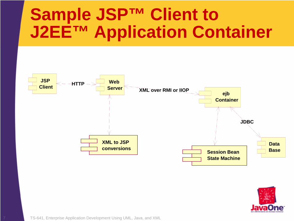
Sample JSP™ Client to J2EE™ Application Container
XML to JSP conversions
Web Server
JSP Client
ejb Container
HTTPXML over RMI or IIOP
Session Bean State Machine
Data Base
JDBC
TS-641, Enterprise Application Development Using UML, Java, and XML8
UML Model Overview
• Use Case Diagram• Collaboration Diagram• Class Diagrams• State Diagrams• Activity Diagrams• Deployment Diagram

TS-641, Enterprise Application Development Using UML, Java, and XML9
Modeling the Application
• Use Case– Use Case Diagrams define the high-level
interactions between external actors and system processes. The Use Case diagram must have an actor, an interaction, and a process
MainProcess
LogonProcessGPublic
SetProfile
Register
Logon

TS-641, Enterprise Application Development Using UML, Java, and XML10
Alternate Implementations
• Realize– The “realize” stereotype on a Use Case
interaction defines alternate mechanisms for implementing the same process
GPublic SetProfile
JSP Logon
(from JSP Implementation)
XSL Logon
(from XSL Implementation)
LogonProcess
Logon
<<realize>>
<<realize>>

TS-641, Enterprise Application Development Using UML, Java, and XML11
User Artifacts
• Each interaction on a Use Case process contains artifacts, these artifacts are tangible attributes provided to the Actor or input artifacts from the Actor to the process. For a Logon:– UserName– UserPassword
LogonProcess
Logon
GPublic

TS-641, Enterprise Application Development Using UML, Java, and XML12
Collaboration Diagram
• Collaboration Diagrams define the implementation for each Use Case interaction
LogonPage : (Logical
UserValidation : (Logical
TryAgain Page : (Logical
FailPage : (Logical
MainMenuPage : (Logical
1: Submit
4: Retry
5: Submit 3: Fail
2: Good

TS-641, Enterprise Application Development Using UML, Java, and XML13
Storyboard Interface Objects
• Storyboard interface objects identify user input and output artifacts. These objects will identify the types of artifacts used within the system for the Use Case interaction
LogonPage : LogonPageSB
UserValidation : (Logical
1: Submit
5: Submit 3: Fail
2: Good
TryAgain Page : TryAgainSB
FailPage : FailLogonSB
MainMenuPage : MainMenuSB
4: Retry
LogonPageSBUserNameLabel : Label = User Name:UserName : Edit = UserNamePasswordLabel : Label = Password:Password : Password = UserPasswordHidden1 : Hidden = SomeFieldrule : rule = LogonValidation event=logoSubmit : link = Submit
<<StoryBoard>>

TS-641, Enterprise Application Development Using UML, Java, and XML14
Decision Control Process Flow Objects• Through the Collaboration diagram choices
or decisions are made directing the diagram flow. Control process flow objects define the domain logic class specifications that will govern these decisions
LogonPage : LogonPageSB
UserValidation : (Logical
1: Submit
5: Submit 3: Fail
2: Good
TryAgain Page : TryAgainSB
FailPage : FailLogonSB
MainMenuPage : MainMenuSB
4: Retry
Decision Object
TS-641, Enterprise Application Development Using UML, Java, and XML15
LogonPageSBUserNameLabel : Label = User Name:UserName : Edit = UserNamePasswordLabel : Label = Password:Password : Password = UserPasswordHidden1 : Hidden = SomeFieldrule : rule = LogonValidation event=logoSubmit : link = Submit
<<StoryBoard>>
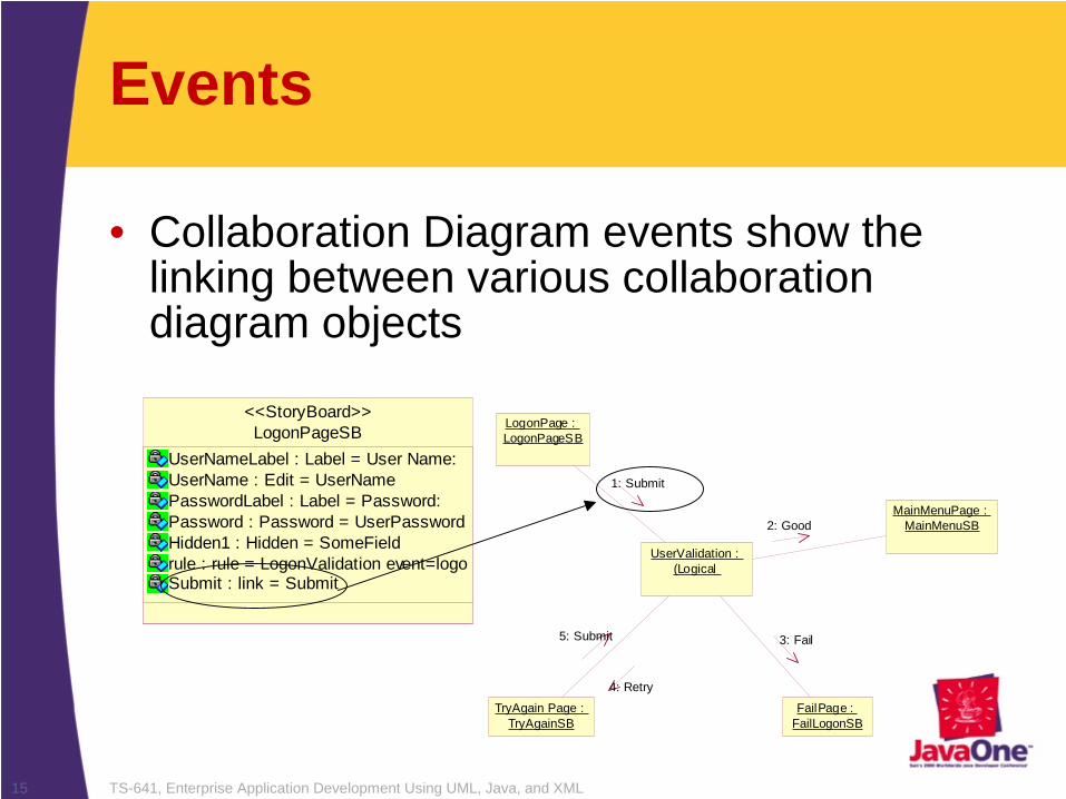
Events
• Collaboration Diagram events show the linking between various collaboration diagram objects
LogonPage : LogonPageSB
UserValidation : (Logical
1: Submit
5: Submit 3: Fail
2: Good
TryAgain Page : TryAgainSB
FailPage : FailLogonSB
MainMenuPage : MainMenuSB
4: Retry

TS-641, Enterprise Application Development Using UML, Java, and XML16
LogonPageSBUserNameLabel : Label = User Name:UserName : Edit = UserNamePasswordLabel : Label = Password:Password : Password = UserPasswordHidden1 : Hidden = SomeFieldrule : rule = LogonValidation event=logoSubmit : link = Submit
<<StoryBoard>>
Storyboard Class Specifications• The storyboard class specification identifies
the ordered set of artifacts and events that this storyboard object element will contain
Artifacts

TS-641, Enterprise Application Development Using UML, Java, and XML17
HTML Pages
• Each storyboard class specification is linked to an HTML page that will be processed to create the XSL or JSP interface definition

TS-641, Enterprise Application Development Using UML, Java, and XML18
HTML Pages
• The HTML pages will contain tokens identifying the XML abstract semantic names representing the use case artifacts coming and going from the control process flow

TS-641, Enterprise Application Development Using UML, Java, and XML19
XML DTD/Schema Modeling
• Modeling the XML schema information within UML provides a visual representation of the XML documents structure. The modeled XML document also provides runtime information and model time checking for collating the use case artifacts with the XML elements
– Sample Company Person XML relating to the LogonPage
logonFormToPersonCtlUserName = PersonCtlUserNamePassword = PersonCtlPassword
<<XMLTransform>>
LogonPageDTD
<<AttributeAccess>> getXML_PersonCt lPersonId()<<AttributeAccess>> getXML_PersonCt lFirstName()<<AttributeAccess>> getXML_PersonCt lMiddleName()<<AttributeAccess>> getXML_PersonCt lLastName()<<AttributeAccess>> getXML_PersonCt lUserName()<<AttributeAccess>> getXML_PersonCt lPassword()<<AttributeAccess>> getXML_UserName()<<AttributeAccess>> getXML_Password()<<AttributeAccess>> getXMLMapPersonCtl()<<AttributeAccess>> getXMLMapLogonPageSB()
<<ControlPF>>
PersonCtl
PersonId : IntegerFirstName : StringMiddleName : StringLastName : StringUserName : StringPassword : String
(from DataAccess)
<<ControlDA>>
<<XMLMap>>
LogonPageSB
UserNameLabel : Label = User Name:UserName : Edit = UserNamePasswordLabel : Label = Password:Password : Password = UserPasswordHidden1 : Hidden = SomeFieldrule : rule = LogonValidation event=logoSubmit : link = Submit
(from StoryBoardObjects)
<<StoryBoard>>
<<XMLMap>>
TS-641, Enterprise Application Development Using UML, Java, and XML20
XML Mappings
• UML Factory provides an abstract mapping between XML elements and semantic names. These Mappings allow isolation between the arbitrary physical representation of a data element, and a logical name or handle to access and manipulate that element– Semantic Names
• Semantic Names identify abstract textual identifiers for elements, or attributes, within the XML document
– XML Element Mappings• XML element mappings identify the arbitrary physical XML
element definition. The XML mappings identify XML text, cardinality, attributes, and schema information

TS-641, Enterprise Application Development Using UML, Java, and XML21
XML Mapping Example
• Generated semantic mappings to sample Company Person XML
mXMLMaptestDTD = new XMLMap();mXMLMaptestDTD.addMapping("TestXML", "xml");mXMLMaptestDTD.addMapping("XmlName", "xml/name");mXMLMaptestDTD.addMapping("Company", "xml /company");mXMLMaptestDTD.addMapping("CompanyName", "xml/company#name");mXMLMaptestDTD.addMapping("CompanyCity", "xml/company#city");mXMLMaptestDTD.addMapping("Person", "xml/company* /person");mXMLMaptestDTD.addMapping("FirstName", "xml/company/person#fname");mXMLMaptestDTD.addMapping("LastName", "xml/company/person#lname");

TS-641, Enterprise Application Development Using UML, Java, and XML22
XML Mappings to “JSP™ tags”• The token semantic names within the HTML
page associate with storyboard class specifications are substituted with methods to extract semantic data from the XML document representing the Storyboard interface object

TS-641, Enterprise Application Development Using UML, Java, and XML23
XML Mappings to XSL tags
• In like manner, the token semantic names within the HTML page associated with storyboard class specifications are replaced with XSL syntax to transform the XML document representing the Storyboard interface object

TS-641, Enterprise Application Development Using UML, Java, and XML24
Storyboard Events
• The storyboard class specification objects contain events that will fire into the application, transitioning through the designed collaboration diagrams– If the target object of a collaboration diagram
event is another interface element then that storyboard interface element will be displayed
– If the target object is a decision point then the class specification defined for that decision logic would be sent the event through the UML state machine implementation

TS-641, Enterprise Application Development Using UML, Java, and XML25
LogonPageSBUserNameLabel : Label = User Name:UserName : Edit = UserNamePasswordLabel : Label = Password:Password : Password = UserPasswordHidden1 : Hidden = SomeFieldrule : rule = LogonValidation event=logoSubmit : link = Submit
<<StoryBoard>>
Storyboard Events
• The Logon Page Submit link event
LogonPage : LogonPageSB
UserValidation : (Logical
1: Submit
5: Submit 3: Fail
2: Good
TryAgain Page : TryAgainSB
FailPage : FailLogonSB
MainMenuPage : MainMenuSB
4: Retry

TS-641, Enterprise Application Development Using UML, Java, and XML26
Collaboration Decisions
• Decisions are implemented by UML logical classes LogonValidation
MaxTries : int = 3CurrentTries : intValidated : boolean
<<StateMachineMethod>> SubmitValidate(theWidl : Widl) : v oid<<AttributeAccess>> LogonValidation() : v oid<<AttributeAccess>> setMaxTries(aMaxTries : int) : v oid<<AttributeAccess>> getMaxTries() : int<<AttributeAccess>> setCurrentTries(aCurrentTries : int) : v oid<<AttributeAccess>> getCurrentTries() : int<<AttributeAccess>> setValidated(aValidated : boolean) : v oid<<AttributeAccess>> getValidated() : boolean<<AttributeAccess>> inWidl(theWidl : Widl) : booleanisValid() : booleanisMaxAttempts() : boolean<<StateMachineMethod>> GoodGood(theWidl : Widl) : v oid<<StateMachineMethod>> FailFail(theWidl : Widl) : v oid<<StateMachineMethod>> Retry Retry (theWidl : Widl) : v oid<<StateMachineMethod>> DoneEnd(theWidl : Widl) : v oid<<AttributeAccess>> setPersonCtl(aPersonCtl : PersonCtl) : v oid<<AttributeAccess>> getPersonCtl() : PersonCtl
<<ControlPF>>
LogonPage : LogonPageSB
UserValidation : (Logical
1: Submit
5: Submit 3: Fail
2: Good
TryAgain Page : TryAgainSB
FailPage : FailLogonSB
MainMenuPage : MainMenuSB
4: Retry

TS-641, Enterprise Application Development Using UML, Java, and XML27
Control Process Flow Class Specification• The control process flow class specification
provides the logical implementation making decisions through the use case collaboration process. The UML control process flow stereotyped class specification is generated into Java™ source code with all the static and dynamic behavior required for:– Receiving input events– Managing persistent data– Manipulating Interface XML documents – Returning information to the process – Maintaining state information of the application

TS-641, Enterprise Application Development Using UML, Java, and XML28
Receiving Events
• When a user activates an event from an interface object, that event is sent into the state machine. All information coming into the state machine is contained within an XML document

TS-641, Enterprise Application Development Using UML, Java, and XML29
Control Process Class State Machines
Start
End
Validate
Retry
Fail
Goo d
Done[ Continue ]
Done[ Continue ]
Done[ Continue ]Se ts Widl Return results="Retry"
Sets Widl Return results="Good"
Sets Widl Retu rn resul ts=" Fai l"
Goo d[ isVa lid() ]
Fail [ isMaxAttempts() && !i sValid() ]Retry[ !isMaxAttempts() && !isValid() ]
SubmitLogonValidationMaxTries : int = 3CurrentTries : intValidated : boolean
<<StateMachineMethod>> SubmitValidate(theWidl : Widl) : v oid<<AttributeAccess>> LogonValidation() : v oid<<AttributeAccess>> setMaxTries(aMaxTries : int) : v oid<<AttributeAccess>> getMaxTries() : int<<AttributeAccess>> setCurrentTries(aCurrentTries : int) : v oid<<AttributeAccess>> getCurrentTries() : int<<AttributeAccess>> setValidated(aValidated : boolean) : v oid<<AttributeAccess>> getValidated() : boolean<<AttributeAccess>> inWidl(theWidl : Widl) : booleanisValid() : booleanisMaxAttempts() : boolean<<StateMachineMethod>> GoodGood(theWidl : Widl) : v oid<<StateMachineMethod>> FailFail(theWidl : Widl) : v oid<<StateMachineMethod>> Retry Retry (theWidl : Widl) : v oid<<StateMachineMethod>> DoneEnd(theWidl : Widl) : v oid<<AttributeAccess>> setPersonCtl(aPersonCtl : PersonCtl) : v oid<<AttributeAccess>> getPersonCtl() : PersonCtl
<<ControlPF>>

TS-641, Enterprise Application Development Using UML, Java, and XML30
WIDL
• WIDL is a Web Interface Definition Language specification – The WIDL contains an event, process, and structured records
defining behavior and data together within a single XML document package
– Event or Method• The method described within the WIDL is the event name coming
into the state machine– Process
• The WIDL process attribute identifies the executable Java class that will receive the WIDL and respond to the method event. Theprocess name can be a fully qualified Java class or an abstract object name. Containers receiving the WIDL input from either session beans, JMS messaging Queue implementations etc., must have a mechanism to late bind the WIDL event to the correct process

TS-641, Enterprise Application Development Using UML, Java, and XML31
WIDL Records
The WIDL contains three records for input information, output information and return information. These records can be populated with attributes or complete XML documents• Input Record
– Our example for the Web application will use the input record to contain information coming from the Web interface into the process logic
• Output Record– The example WIDL use the output record of the WIDL to contain
Return Page or XML document information back to the Web interface• Return Record
– The WIDL return record contains results information for evaluating decisions to the collaboration process flow. The result Attribute within the WIDL Return record contains the return events from the control process flow class specification

TS-641, Enterprise Application Development Using UML, Java, and XML32
State Machines
• State machines define the possible events coming into a dynamic class and the state transitions for those events. The state machine diagram provides a readable definition of the dynamic behavior for a given class specification
LogonPage : LogonPageSB
UserValidation : (Logical
1: Submit
5: Submit 3: Fail
2: Good
TryAgain Page : TryAgainSB
FailPage : FailLogonSB
MainMenuPage : MainMenuSB
4: Retry
Start
Validate
Retry
Fail
Goo d
Done[ Continue ]
Done[ Cont
Done[ Continue ]Se ts Widl Return results="Retry"
Sets Widl Return results="Good"
Goo d[ isVa l id() ]
Fail [ isMaxAttempts() && !i sValid() ]Retry[ !isMaxAttempts() && !isVal id() ]
Submit

TS-641, Enterprise Application Development Using UML, Java, and XML33
States and Transitions
• States– States define the process stops through the
state machine• Event Transitions
– Transitions define the event causing a transition from one state to another state
• Event State Methods– Event state methods are the implied action
behaviors when an event transition occurs. These event state methods are implemented through UML activity diagrams

TS-641, Enterprise Application Development Using UML, Java, and XML34
State Diagram Elements
Start
Validate
Retry
Fail
Goo d
Done[ Continue ]
Done[ Continue ]
D [ C ti ]Se ts Widl Return
Sets Widl Return results="Good"
Goo d[ isVa lid() ]
Fail [ isMaxAttempts() && !i sValid() ]Retry[ !isMaxAttempts() && !isValid() ]
Submit
Event Transition Event State Method
State
TS-641, Enterprise Application Development Using UML, Java, and XML35
State Timing
• Guard Conditions– Guard conditions imply a synchronous transition exiting a
given state. The guard conditions contain boolean logic to determine which exit transition will be traversed
• Asynchronous– Asynchronous events have no guard conditions and are
triggered from some external source. That source is typically a user interface link artifacts
• Synchronous– Synchronous events transition automatically and internal
to the state machine. Synchronous events are identified as exit events from a state containing guard conditions

TS-641, Enterprise Application Development Using UML, Java, and XML36
Transition Timing Example
Start
Validate
Retry
Fail
Goo d
Done[ Continue ]
Done[ Continue ]
D [ C ti ]Se ts Widl Return
Sets Widl Return results="Good"
Goo d[ isVa lid() ]
Fail [ isMaxAttempts() && !i sValid() ]Retry[ !isMaxAttempts() && !isValid() ]
Submit
Asynchronous TransitionSynchronous Guarded Transition

TS-641, Enterprise Application Development Using UML, Java, and XML37
Setting Animation Points
• Within the state machine any transition can be identified within the UML diagram as an animation point. When the application is executed the UML document will be displayed selecting the animation location
Start
Validate
Retry
Fail
Goo d
Sets Widl Return results="Good"
Goo d[ isVa lid() ]
Fail [ isMaxAttempts() && !i sValid() ]Retry[ !isMaxAttempts() && !isValid() ]
Submit
Animation Point

TS-641, Enterprise Application Development Using UML, Java, and XML38
Activity Diagrams
• Activity Diagrams implement the behavior of algorithms for UML class specification methods
S ta rt
V a l i d a te
R e try
F a il
Go o d
D o n e [ C o n t i n u e ]
D o n e [ C o n t i n u e ]
D o n e [ C o n t i n u e ]S e ts W i d l R e tu rn re s ul ts =" R e try "
S e ts W i d l R e tu rn re su l ts= " G o o d "
Go o d [ is Va l i d () ]
F a i l [ i sM a x A t te m p ts () & & ! i sV al i d ( ) ]R e t ry [ ! i sM a xA tte m p ts() & & ! i sV a l i d () ]
S u b m i t
Event State Method

TS-641, Enterprise Application Development Using UML, Java, and XML39
UML Object Navigation Notation• Activity Diagrams are represented in UML Object
Navigation Notation. This notation manipulates the objects with their public attributes and methods. Using the object notation and Activity Editor within UML Factory you can define the complete behavior for a method implementation
sUserName = theWidl.getInputParameter( "UserName" )sPassWord = theWidl.getInputParameter( "Password" )this.setValidated( false )

TS-641, Enterprise Application Development Using UML, Java, and XML40
Designing an Activity

TS-641, Enterprise Application Development Using UML, Java, and XML41
Accessing a Data Base
• Through the activity diagram implementations we can manipulate our database objects, defining the operations for all our database elements as required
aPerson.PersonCtl( )aPerson.setFirstName( sUserName )aPerson.setPassword( sPassWord )this.setValidated( aPerson.load( ) )

TS-641, Enterprise Application Development Using UML, Java, and XML42
Manipulating XML
• Within the activity diagrams we also define the XML manipulation for retrieving and building the XML documents going between the process flow logic and user interface elementssValue= new String( "PassageSoftware" );
aXMLMap.insert( this.getXML_CompanyName( ), sValue );sValue= new String( "Richmond, VA" );aXMLMap.insert( this.getXML_CompanyCity( ), sValue );
aXMLMap.insert( this.getXML_Person_NODE( ), null );sName= new String( "Dick" );
sLName= new String( "Douglas" );aXMLMap.insert( this.getXML_FirstName( ), sName );aXMLMap.insert( this.getXML_LastName( ), sLName );

TS-641, Enterprise Application Development Using UML, Java, and XML43
Intelligent Advisor Code view
• The UML Factory Intelligent Adviser allows us to view the code generation results while designing the UML activity diagrams

TS-641, Enterprise Application Development Using UML, Java, and XML44
Setting Animation Points
• Any activity within the activity diagrams can also have animation points defined. When the application is executing the activity diagram will display and select the activities with animation settings
Animation Points

TS-641, Enterprise Application Development Using UML, Java, and XML45
Generating the Application
• After the static and dynamic elements of our application are defined we can organize these elements into UML Component Diagrams to define deployment definitions. From the components definitions we can then generate the complete Java class code, compile the code and package it into the appropriate application JAR

TS-641, Enterprise Application Development Using UML, Java, and XML46
Collaboration Diagram XML Generation• The collaboration diagram information for
our use case definitions is also generated into an XML description document identifying the interface elements, XML mappings, and control process flow information. This XML document then becomes the basis for execution through the application – The XML document defines the process flow
through the application– The engine that iterates the collaboration
diagram XML document was also designed and generated from a UML model

TS-641, Enterprise Application Development Using UML, Java, and XML47
Control Process Flow Generation• Dynamic behavior represented within an
application is designed within a control process flow class specification. The following sections will briefly illustrate the generation processing capabilities for dynamic behavior within a UML environment. The following code examples were completely generated from the UML model

TS-641, Enterprise Application Development Using UML, Java, and XML48
Generating the UML Class Specification• Looking at the State Machine implementation
– Current State– Incoming Event– Synchronous Transitions– Asynchronous Transitions– Start and End States
• Packages, imports, declarations– Java package specifications can be explicitly or implicitly
defined by the class locations within the UML model • Association and Attribute implementations
– Association implementations generate both the container and access methods for the stereotyped association. The type of container and resulting access methods are defined by the stereotype applied to the association between class specifications

TS-641, Enterprise Application Development Using UML, Java, and XML49
Method Implementation
• Activity Diagram Method Implementations– Activity diagrams are generated following the UML Object
Notation. The activity generation can be viewed with either as a fully generated class or using the Intelligent Advisor codewindow
• Round Trip engineering– Roundtrip engineering allows developers to hand edit code
generated from the UML Diagram. By Identifying elements which have been hand edited, the UML Factory generator will leave the method implementation as edited without forward generating from the model. The developer controls the granularly of roundtrip engineering
• UML Model Animation code– Animation points placed within the code can be turned
off for individual points, the entire model being generated, and also ignored, from run time configuration properties

TS-641, Enterprise Application Development Using UML, Java, and XML50
Executing the Architectures
• The following demonstrations will walk through executing the various architectures from the complete components on different types of application servers

TS-641, Enterprise Application Development Using UML, Java, and XML51
Sample JSP™ Client to J2EE™ Application Container
XML to JSP convers ions
Web Server
JSP Client
ejb Container
HTTPXML over RMI or IIOP
Session Bean State Machine
Data Base
JDBC
TS-641, Enterprise Application Development Using UML, Java, and XML52
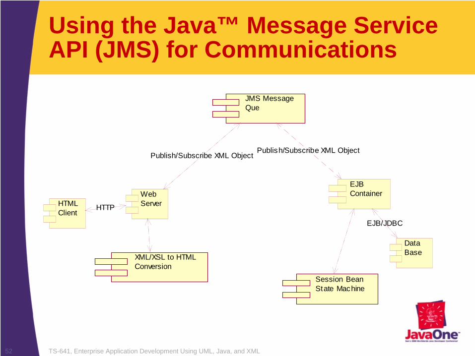
Using the Java™ Message Service API (JMS) for Communications
HTML Client
Web Server
XML/XSL to HTML Conversion
JMS Message Que
EJB Container
Session Bean State Machine
Data Base
HTTP
Publish/Subscribe XML ObjectPublish/Subscribe XML Object
EJB/JDBC

TS-641, Enterprise Application Development Using UML, Java, and XML53
Summary
• This concludes the presentations and demonstrations for building n-tier enterprise applications with UML and XML data representations
• The demonstrations have illustrated the ability to completely model both static and dynamic application behavior within a UML model
• The UML model also defined components and deployment into multiple configurations
• The modeled demonstration illustrated the ability to use the same components within different J2EE™ platform-enabled implementations on multiple architectural environments
TS-641, Enterprise Application Development Using UML, Java, and XML54
Enterprise Development Benefits• Enterprise computing can improve the software
development process by combining the descriptive power of the UML notation, and the flexible data representation and distribution capabilities of XML with the object oriented, network, and portable capabilities of Java technology
• Combining these technologies enables organizations to manage components increasing reuse, visibility, and implementation understanding; effectively reducing the complexity and total cost of ownership for deploying n-tier enterprise applications

TS-641, Enterprise Application Development Using UML, Java, and XML55