entellisys low-voltage switchgear... · traditional low voltage power circuit breaker testing...
TRANSCRIPT
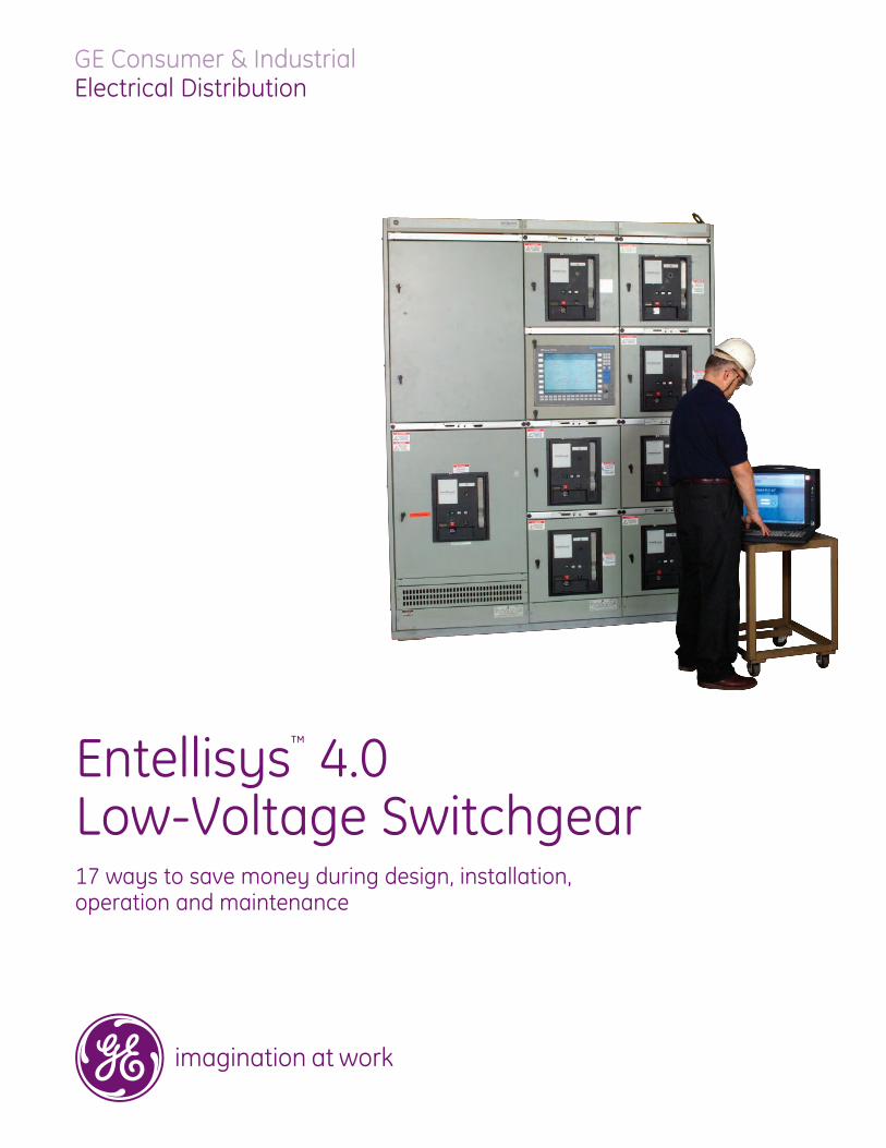
GE Consumer & IndustrialElectrical Distribution
Entellisys™ 4.0Low-Voltage Switchgear17 ways to save money during design, installation, operation and maintenance
imagination at work

2
Entellisys™ 4.0 is the sensible choice to save you moneyover the lifetime of your system.
Entellisys Low-Voltage Switchgear is the first system to provide the power ofknowledge about the entire switchgear lineup.
This power can be used:• by the engineer to improve protection, • by the installing contractor to shorten installation time, • by the operator to stay out of the arc flash zone, • by the maintenance personnel to save maintenance time
and money, and • by the owner to adapt the equipment to the dynamic needs
of the facility.
Entellisys helps to reduce costs, shorten schedules, and increase reliabilitythroughout the process of designing, installing, maintaining, and owningyour low-voltage power distribution switchgear.
Entellisys is becoming the preferred solution in critical applications such as data centers, hospitals, petro/chem facilities and airports around the world.State-of-the-art protection, monitoring and control make it the intelligentchoice to provide reliable power distribution now and in the future.
Contact your account manager and request a financial savings report, customized for your application.

3
1. Easy to add or modify functionalityInformation is constantly changing during the design of aproject, which affects the design of the power system.Entellisys’ software-based architecture makes it easy forengineers to modify functionality at almost any time duringthe design and build phase without impacting the schedule.No longer do discrete devices have to be procured, equipmentmodified and wiring run. A change in options can be madeeasily with updated software. This translates to dollars saved.And this flexibility remains for the life of the equipment.
2. Finally, a holistic approach to low-voltageswitchgear dynamics
Traditional switchgear trip systems can only react to whatthey know – the current magnitude and time for one particularcircuit. Entellisys is the first low-voltage circuit-protectiontechnology that overcomes this limitation. The Entellisys single-processor concept bases control of every circuit breaker in theswitchgear on what is best for the entire line-up under thesystem’s exact conditions at that exact moment. Each tripfunction is no longer limited to the current information availableat its particular circuit. With Entellisys, each circuit breaker iscontrolled with full information about every current, voltageand circuit breaker in the switchgear.
3. Now you don’t have to sacrifice selectivity for protection
Entellisys knows the magnitude and the location of a fault.As a result, when Zone Selective Interlocking and BusDifferential are applied, you achieve both fast protection(detection as fast as .25 ms) and selectivity. You can nowhave the best of both worlds: fast protection with minimaloutage potential.
4. Creating future value for the userEntellisys architecture enables the equipment to stay currentwith technology. This translates the ability to add new func-tionality as it is developed and implementing it as the facility’sneeds change – without incurring downtime. No longer is theowner stuck with traditional type equipment that is difficultto add protection, metering or control features, and usuallyrequires downtime for the change.
Project Design

4
5. Fast installationEntellisys streamlined architecture minimizes wiring andshipping split terminations by reducing the amount of wiringin equipment – in some cases up to 70%. That makes instal-lation fast and efficient.
6. Faster start-up using diagnostics for troubleshootingThe Sequence of Events log in Entellisys provides a detailedhistory of the system dynamics with a resolution of 0.5ms.Instead of guessing at what might be occurring, personnelcan quickly know exactly what is happening and quicklyremedy the situation.
Traditional switchgear wiring.
Entellisys’ greatly reduced wiring means many fewer terminations and faster, easier installations.
7. Streamlined interface to building and power management systems
Traditional switchgear using discrete devices forces the integrator to interface with many devices within eachswitchgear lineup. Entellisys streamlines the integrationprocess in a number of ways.
Only one interface is required for the entire lineup. That meansinstead of interfaces for each type of device, one interfaceto the Modbus® register map provides access to thousandsof registers for data collection as well as control. The sameinterface can be used for each Entellisys system, and theonly thing that changes is the circuit breaker identification.
Entellisys provides all of the metering values in IEEE floatingpoint format so no scaling is required, the values are alreadyconverted to amps and volts. This is not typical in the industry,and most devices require the integrator to capture the currenttransformer ratios and calculate each value for each circuit,which is time-consuming and requires additional start-uptime in validating.
Installation and Start-Up

5
8. Increased reliabilityPower distribution systems are designed to provide continuityof service. Compared to traditional switchgear, Entellisysarchitecture provides increased reliability through stream-lined hardware and built-in redundancy. Instead of manydevices for monitoring, protection and control, and miles ofwire, Entellisys has one set of hardware to provide the entirerange of possible needed functionality. This simplicity (fewercomponents, less wiring) increases reliability.
Traditional switchgear almost always has only one level ofdevice functionality. Entellisys has standard redundant centralprocessing units, communication buses and UPSs. As a simpleexample, two 90% reliable devices when used in seriestranslate to 81% reliability, three equals 72.9%, etc. The same90% reliable components, used in parallel, yield 99% reliability.
Traditional switchgear doesn’t necessarily know a function isnot working until it is called upon to act. Entellisys continuouslymonitors the health of the system components and, if some-thing is not functioning properly, the instance is identified bythe system health screen, the event log, or can be configuredas an alarm. The alarms can be emailed to up to 4 addresses,providing immediate feedback that attention is needed.
9. Increased system availabilityWhat matters to you is that your switchgear is performingas needed, providing protection, monitoring and control.With the redundant systems and system health monitoring,you are notified if something needs attention. Due to theredundant architecture, it is possible to service the systemlevel devices and maintain service – not something you typi-cally even know about in traditional switchgear, let aloneresolve in a non-intrusive manner.
10. Decreased downtime using low-voltageswitchgear diagnostics
Power systems are dynamic and, until Entellisys, it was veryhard to discern what exactly has occurred during a distur-bance. In traditional systems, you may have some trip typeindication, possibly a waveform on a circuit or two, andsome type of time stamping that may not be synchronizedacross devices.
Entellisys provides a detailed log of all of the system’s pro-tection functions (pick-up, drop-out, etc.) as well as detailedfault reports that include the current and voltage for everyEntelliGuard™ circuit breaker at the time of the event. Anindustry first, Entellisys’ waveform capture records the current
System Operation
Reliability comes from redundant CPUs, UPSs, communications and wiring

6
and voltage waveforms for every EntelliGuard circuit breaker,as well as the open and close commands and actions. All of theevents, data and waveforms are synchronized to within tensof microseconds, giving you a detailed chronological log ofsystem dynamics.
This is a powerful tool in determining exactly what occurredduring a disturbance. Entellisys also provides various dataand protective alarm settings to provide warnings of possibleunfavorable conditions, allowing you to take action and preventan outage. Ask GE for real-life examples of how Entellisysidentified issues that prevented an outage and providedinformation on root-cause system conditions.
11. Reduced arc-flash hazardEntellisys offers advanced protection modes, known aszone-based protection, that include bus differential, directionalzone-selective interlocking and multi-source ground faultprotection. This protection enables detection – as fast as25ms – of arcing faults in the equipment while maintainingselectivity. The energy let-through from a fault is greatlyreduced, often resulting in reduced hazard risk categories(HRC). The reduced HRC category can mean less cumbersomepersonal protective equipment (PPE) for the operators aswell as less potential damage to downstream equipment.
12. Move operators outside the flash protectionboundary
The Near-Gear Human Machine Interface allows for thecomplete interaction with the Entellisys system. The touchscreen display can be placed up to 300 cable feet away
from the lineup, which is generally far outside the flash pro-tection boundary. The operator can fully interact with theEntellisys system, view all parameters and open and closecircuit breakers without being in front of live equipment.
13. Move operators away from the gear during racking operations
Entellisys’ remote racking device eliminates the need foroperators to stand in front of a moving circuit breaker duringracking-out or racking-in of an EntelliGuard circuit breaker.
14. Efficient remote communications Entellisys provides enhanced communication capabilities forthe user. Alarms can be easily configured and can beemailed to up to four different email addresses. Entellisyscommunicates all status data, alarms, metering, event log,etc., digitally over Modbus TCP/IP. No additional switches orhardware are needed to get this information. The amount ofinformation available, all synchronized, is unprecedented.The register map is predefined and is identical for all lineups.The register map uses a “source” structure. Each circuitbreaker is a source and is consequently another incrementin the register map. Once a substation is integrated, thattemplate can be used for all substations, requiring only thenumber of circuit breakers to change.

7
15. Streamlined circuit breaker testing The Entellisys architecture of circuit hardware (current sensors,Messengers) is in the equipment, not on the circuit breaker. Thattranslates into efficient maintenance procedures for testing.
Traditional low voltage power circuit breaker testing requirespersonnel to remove the circuit breaker from the gear, moveit to a test station for high current injection testing and returnand rack the circuit breaker back into the switchgear. This isnot only time-consuming, it increases the probability of dam-age or an arcing fault due to the movement and handling ofthe circuit breaker in and out of the gear.
Entellisys changes this. The current sensors’ integrity can bedetermined by simply reading the metering information on theHMI for each circuit. The Entellisys test kit can be connectedto the HMI via the USB port to download all of the circuit breakersettings to the test kit. Then, individually, each EntelliGuardcircuit breakers is racked to the Test position. The Entellisystest kit plugs into the Messenger test port and you can runautomatic or customized test cases. The test kit sends simu-lated current signals to the Messenger, and the entire protectionlogic (Messenger, communication bus, CPUs) is exercised. Atest kit indicates trip timing and provides a test report file.Consequently, EntelliGuard circuit breakers do not requirehigh current injection testing. This saves you time andresources while providing comprehensive testing.
16. Predictive maintenance information Entellisys provides circuit breaker operating data so you canimprove your maintenance timing. For each circuit breaker,Entellisys tracks the total number of operations, no loadoperations, load operations and fault operations as well asthe date of the last operation. You can enter threshold levelsfor each type of operation and the system will generate analarm and send emails when the threshold is crossed.
Entellisys also calculates the percentage of the total load lifethat has been used, both mechanically and electrically. Itcan activate alarms and associated emails for various stagesduring mechanical and electrical life. Entellisys also tracksthe date and time each circuit breaker was initially energizedand, on every anniversary, an alarm is activated and anevent is recorded. Now you have data to determine themaintenance required instead of just a time-based system.
17. Fewer spare circuit breakers The circuit-specific components (current sensors andMessengers) are located in the equipment, making circuitbreakers more interchangeable. Because you no longer haveto consider frame size, sensor rating and trip unit type, youcan stock fewer spare circuit breakers. In fact, EntelliGuardcircuit breakers make it even easier for you. All 800A, 1600Aand 2000A circuit breakers are the same physical size, as arethe 3200A and 4000A breakers. So you can use a higher ratedcircuit breaker in a lower rated cubicle of the same envelope,which also reduces the number of spares. For example, if thereare 800A, 1600A and 2000A feeder circuit breakers, insteadof needing one of each frame size/CT/trip unit combination,one 2000A EntelliGuard circuit breaker will meet the need.
Maintenance

8
Layout and Sizing
Entellisys indoor low voltage switchgear height is 92" (97"over the top wiring trough and 103.5" over the optionalbreaker hoist). The available breaker stacking space is 84".
Breaker frame size and type determine the width of the breakersections and also the minimum depth of the switchgear line-up.Refer to tables below for properly sizing Entellisys line-ups. Thedepth of the entire line-up is determined by the deepest devicein the line-up. For example, a line-up with an EGF-20 breakerwith a fuse roll-out (depth – 60") and EGF-08 breakers (depth –67") would be a minimum of 67" deep – the EGF-08 being thedeepest device. Also refer to the section arrangements on thefollowing pages for available breaker stacking configurations.
Switchgear Layout Considerations1. Sections on the following pages can be bussed together
if there are matching bus levels in the adjacent sections.Refer to the sample ENTELLISYS line-up.
2. Any breaker compartment shown on the section drawingscan be made blank to provide additional space formounting Entellisys devices. See Tables 16.5 and 16.6 fordevice and cubicle data.
3. The ampere ratings shown beside each breaker symbolindicate the range of frame sizes that are allowed in theparticular section arrangement. This takes into consider-ation the temperature rise in the section due to breaker
loading. Refer to ANSI C37.20.1-2002 para 8.4.2.3 forcumulative circuit breaker loading guidelines.
4. Devices cannot be mounted on breaker cubicle doors. 5. 3200A, 4000A, and 5000A fuse roll-outs are the same size
as their respective breakers, therefore any compartmentshown with a 3200, 4000, or 5000 amp breaker will alsoaccommodate a fuse roll-out and vice versa.
6. Front busway connections to a circuit breaker require ablank compartment above the breaker for busway above ora blank compartment below the breaker for busway below.
7. Use of fused breakers does not necessarily require200kA bus bracing. Bus bracing should be based on theavailable short circuit current on the switchgear bus.
8. 200kA bus bracing can limit feeder breaker placement.200kA bus bracing does not allow adjacent 22 inch widesections.
9. Factory review of layout is required for bus bracinggreater than 100kA
10. Some cable entrance designs are not suitable for serviceentrance. Consult the factory if service entrance isrequired for the incoming cable section.
11. Additional cable and conduit space is available by makingbreaker sections wider (22 inch wide to 30 inch wide or30 inch wide to 38 inch wide) or by making the line-updeeper (7 or 14 inches). Refer to the tables below.
Indoor Enclosure Depth Options
Available Depth Options
Front compartment 30"
30" (std) 37" (7" ext) 44" (14" ext)
37"
30" (std) 37" (7" ext) 44" (14" ext)
Rear compartment (Std depth or 7" or14" rear extension
Total depth 60" 67" 74" 67" 74" 81"
Entellisys Switchgear Section Sizing
1 Breaker and fuse roll-out must be mounted in separate vertical sections.2 81" depth available only when these devices are used in a line-up with items identified with **.3 Section width can be increased for additional cable / conduit space. 22" sections can be increased to 30" wide, 30" wide sections can be increased to 38" wide.
BreakerType
Device Combination or Bus Rating
Frame Size(Amperes)
Breaker Cubicle Vertical Height (Inches)
Minimum SectionWidth3 (Inches)
Minimum Equipment Depth[Front/Rear Compt] (Inches)
Optional EquipmentDepth (Inches)
EGS-08
800
21 22
60 [30 /30] 67/74EGH-08EGX-08EGF-08 67 [37 /30] 74/81**EGS-16
160060 [30 /30] 67/74
EGH-16 60 [30 /30] 67/74EGF-16 67 [37 /30] 74/81**EGS-20 2000 60 [30 /30] 67/74
EGF-20 with fuse roll-out 56
30
60 [30 /30] 67/74/812
EGS-32
3200 3560 [30 /30] 67/74/812
EGH-32 60 [30 /30] 67/74/812
EGX-32 60 [30 /30] 67/74/812
EGF-32 with fuse roll-out 84 38 67 [37 /30] 74/81**EGS-40
400035 30 60 [30 /30] 67/74/812
EGX-40 35 30 60 [30 /30] 67/74/812
EGF-40 with fuse roll-out 84 38 67 [37 /30] 74/81**EGS-50
5000 35 3874 [37 /37] 81**
EGX-50 74 [37 /37] 81**EGF-50 with fuse roll-out1 74 [37 /37] 81**
1600-4000A main bus rating — — — 60 [30 /30] 67/74/812
5000A main bus rating — — — 67 [30 /37] 74/812

Weights and dimensionsSwitchgear WeightsProcedure:A) Add the weight of every vertical section in the lineupB) Add the weight of each breaker and fuse roll-out in
the lineup
EntelliGuard Breaker and Fuse Roll-out Weights, Lbs. (Kg)
9
1 Also includes number of fuse roll-outs in the vertical section.
Section Width
Number of Breaker Compartments1 in Vertical Section
Vertical Section Weights, Lb. (Kg)
22"
1 940 (426)
2 1100 (499)
3 1270 (576)
4 1440 (653)
30"1 1300 (590)
2 1400 (635)
38"1 1660 (753)2 1900 (862)
22" or 30" Auxiliary section 1170 (531)
Device Manual ElectricalEGS / EGH-08 188 (86) 193 (88)
EGX-08 198 (90) 203 (92)
EGF-08 233 (106) 238 (108)
EGS / EGH-16 198 (90) 203 (92)
EGF-16 243 (111) 248 (113)
EGS-20 203 (92) 208 (95)
EGS / EGH / EGX-32 455 (207) 470 (214)
EGS / EGX-40 560 (255) 575 (261)
EGS / EGX-50 600 (273) 615 (280)
2000/3200A fuse roll-out(EG32FRE) 330 (150) 3 fuses – add 75
(34)
4000A fuse roll-out (EG40FRE) 335 (152) 3 fuses – add 90(41)
5000A fuse roll-out (EG50FRE) 345 (156) 3 fuses – add 90(41)
Entellisys Sample Layout
22"
800-1600A
800-2000A
800-2000A
800-2000A
F22-122"
800-1600A
800-2000A
800-2000A
800-2000A
F22-122" 22"
14"
35"
21"
3200-4000A
800-1600A
800-2000A
800-2000A
800-2000A
800-1600A
800-2000A
800-2000A
800-2000A
UPS'S
CONTROL POWER TRANSFER
MT30-730"
MT30-1930"
35"
MT30-6 F22-130"
F22-1
B/W
MAINTIE
3200-4000A
HMI
TIE
MAINTIE
3200-4000A
42"
CPU'SNETWORK SWITCHES
DIGITAL I/OBUSWAY ABOVE=FRONT POSITION
BUSWAY ABOVE=FRONT POSITION
B/W
92”
Upper Bus
Lower Bus
**Mid (Center) Bus
Special Considerations for 5000 Amp Equipment1. Minimum depth of a 5000A breaker section is 74 inches.2. Upper and lower bus levels are available at 5000 amps.
The center bus level is not available at 5000 amps. 3. 5000 amp bus is available as a bare bus design or with
bus compartment barriers. 4. Sections adjacent to a 5000 amp transformer transition
section must be 30 inches wide, minimum.

10
Where you savetime and money Feature Benefit
Design
Software-based architecture Easy to add or modify functionality during design and addfunctionality as needs change
Single-processor concept Operates based on the entire line-up dynamics rather thanjust one circuit, improving protection
Bus differential & zone selective interlocking Fast and selective protection minimizes let-thru energy thatcan cause equipment damage
Installation
Reduced wiring & components Fast, efficient installation reduces installation costs
Detailed event log (synchronized to tens ofmicroseconds, 0.5ms resolution) Identify root cause of faults quickly, minimizing downtime
Single interface to other systems Easy to customize and interface to such systems BMS or PMCS
Operation
Centralized architecture Increases reliability by reducing wiring and component hardware; provides redundant system
Two systems – redundant CPUs, UPSs andcommunication buses
No single point of failure – reduces risk of unplanned down-time
Advanced warning functionality Alarms and emails provide advanced notice of potentialproblems
Detailed event log Allows you to track root cause of faults quickly with a resolu-tion of 0.5ms to minimize downtime
Event alarms via HMI or email Quick notification of faults to reduce downtime
Bus differential & zone selective interlocking
Fast and selective protection minimizes the arc flash hazardthat can damage equipment
Near-Gear HMI Provides complete interaction with the switchgear outsidethe arc flash hazard boundary
Reduced Energy Let-Thru (RELT) Reduces the risk of arc flash hazard when personnel need towork near the switchgear
Remote racking No need for an operator to face a breaker during rackingoperation
Remote HMI Enables remote, secure access via network or web; reducesthe need to travel to remote sites
High Resistance Ground Fault (HRGF) detection Detects a HRGF and provides an alarm
HRGF location Locates the feeder where the HRGF exists and provides an alarm
HRGF tripping priority Allows user to have priority tripping schemes in the event ofmore than one HRGF at the same time
Separate control stack (CPU, UPS, HMI) Maintenance of components outside the arc flash hazardboundary; HMI on stack outside of the arc flash hazard area
Line-up synchronization via SNTP pulse Syncs clock with facility system-wide time standards tomake is easier to compare event logs within the facility
Ground fault alarm Provides an alarm only - no trip - on ground fault
High current alarm with waveform capture Captures waveform after passing a high current threshold
Remote software for PC, not HMI Communicate with up to 25 line-ups from one PC
Maintenance
Entellisys test kit Streamlined circuit breaker testing and reduced downtime
Predictive maintenance data Schedule maintenance based on usage rather than calendar
Circuit breaker components are located inthe equipment Fewer spare circuit breakers, lower spare parts inventory
Software upgrades Quicker to make changes compared to changing hardware
Simple, intuitive HMI Easy to navigate and understand
Mobile metering No additional meter hardware required if needs change
3.0 4.0
3 3
3 3
3 3
3 3
3 3
3 3
3 3
3 3
3 3
3 3
3 3
3 3
3 3
3 3
3 3
3 3
3 3
3
3
3
3
3
3
3
3 3
3 3
3 3
3 3
3 3
3 3
Features and benefits

GE Consumer & Industrial41 Woodford AvenuePlainville, CT 06062
www.geelectrical.com
DEA-427A (08/07)
imagination at work
Information subject to change at any time without notice. Please verify all details with GE.