engineers - americanradiohistory.com · a broadcast engineering tutorial for non -engineers . ii we...
TRANSCRIPT

NrAt
A BROADCAST ENGINEERING
TUTORIAL
for
ENGINEERS 2nd Edition

4/11k

Preface
Many times, people without engineering backgrounds need to have a general understanding of broadcast engineering issues. This is true for broadcast managers who come from sales, finance or programming backgrounds, for lawyers who work with broadcast clients, and for members of the
financial community who deal with the broadcasting industry. It is also true for engineering trainees who have no engineering experience but who want to develop a
knowledge base from which to launch a broadcast engineering career. This book is written for all of these people. It describes the engineering aspects of broadcast facilities in very general terms with the goal of providing non -engineers with enough knowledge about broadcast engineering to enhance the work they are doing in their respective fields.
In this second edition, new material has been added to
explain digital television technology, and to further explain the digital audio formats that have rapidly become commonplace in radio broadcast studios.
A Broadcast Engineering Tutorial for Non -Engineers

ii
We hope that the information in these pages will help to
further their understanding of our trade, and thus enhance
their ability to perform the broadcast -related functions of
their jobs.
NAB Science and Technology Department
April, 1999
National Association of Broadcasters

111
Table of Contents
Introduction
PART I: THE STUDIO
1
3
Radio Stations 4 Analog Tape Players/Recorders 5
Digital Audio Tape Players/Recorders 17
Compact Disc Players 19
The Mixing Board 21
Telephone Hybrids 25 Microphones, Headphones and Speakers 25
Computers 32 Digital Audio Basics 34
Sampling Rate 39
Bit Rate 40 Compression 41
The AES/EBU Digital Format 43
Distribution Amplifiers and Servers 45
Audio Processing Equipment 47
Emergency Alert System Equipment 58
Television Stations 60 NTSC Video 61
The Horizontal Blanking Interval 68
The Vertical Blanking Interval 70
ATSC Video 73 Pixels 76
Compression 79 Frames 82
Frame Rate 88
Interlacing 90
Multicasting 91
A Broadcast Engineering Tutorial for Non -Engineers
iv
Ancillary Data 95 DTV Audio 96
Timing 101
Audio -Video Synchronization 106 Video Tape Recorders 109 Character Generators 116 Television Cameras 117 Chroma Key and Matte Systems 120 Video Mixing Board 122
Distribution Amplifiers and Routing Switchers 124 Emergency Alert System Equipment 126
PART II: THE STUDIO -TRANSMITTER LINK 129
PART III: THE TRANSMITTER SITE 135
The Stereo Generator 141
Subcarrier Generators 143
The Exciter 159
The Power Amplifier 170 The Transmission Line 172
The Antenna 174 The Remote Control 184
PART IV: REMOTE BROADCASTING FACILITIES 187
PART V: FCC TECHNICAL RULES 191
Conclusion 201
Index 203
National Association of Broadcasters

1
Introduction
In its most general form, a broadcast station consists of two
basic facilities: the studio complex and the transmitter.
The studio complex is the place where the programming
that is broadcast by the station originates. The transmitter
is the device that actually broadcasts the programming
material out over the air. In between the two is a hard-
wired, or wireless, connection called the studio -to -
transmitter link.
Part I of this book will cover the studio. It will describe the
various pieces of equipment that are found in a typical
broadcast studio, and it will explain how they work
together. Part II will cover the studio -to -transmitter link, or
STL. It will explain the different types of STLs and what
the advantages and disadvantages are to using each one.
Part III will cover the transmitter site - including the
transmitter, transmission line and antenna. It will describe
the modifications that the transmitter makes to the program
material received from the studio in order to transport this
material to receivers at distant locations. Part V gives a
general overview of the Federal Communications Commission's technical criteria for allocating broadcast
channels.
A Broadcast Engineering Tutorial for Non -Engineers

2
All three types of broadcast facility (AM, FM and TV) are
covered in this book. When there is little technical difference between two facilities as, for example, is the
case with AM and FM radio studios - they will be covered together.
And now, on to Part I.
National Association of Broadcasters

3
Part. I: The Studio
A Broadcast Engineering Tutorial for Non -Engineers

4
Radio Stations
Many people may find it easiest to understand the operation
of a radio station studio if they compare the studio setup to
that of their home stereo. Generally speaking, the operation
of a radio station studio is very similar to the operation of a
typical home stereo - with the primary differences being 1) there is generally a lot more equipment in a studio setup than in a home stereo, and 2) the studio setup allows the
program material from multiple inputs to be mixed together and then output as a combined signal, while a home stereo
usually only permits a single input source to be sent to the
speakers, headphones, recorder, etc. at any particular time.
The following is a list of some of the equipment that one is
likely to find in a radio studio:
'I Cart ("cartridge") players/recorders Ni Cassette players/recorders
CD players
Ni Computers Ni Digital audio tape players/recorders -Ni Distribution amplifiers
Headphones Ni Microphones Ni Mixing boards
National Association of Broadcasters

5
Ni Reel-to-reel players/recorders "I Speakers 'i Telephone hybrids
In many modern radio studios, analog equipment has been
replaced by new digital equipment because the digital equipment is more reliable and generally permits more efficient use of a station's resources. As we review the
technical characteristics of the various pieces of common studio equipment, we will start with analog equipment --
which was heavily used in the past and is still used in many studios today -- and lead into digital equipment -- which is
in many studios today and will be in all studios of the future.
Analog Tape Players/Recorders
Cart, cassette and reel-to-reel players/recorders all have one
major thing in common: they all use magnetic tape as the medium on which audio information is stored. Each of these devices has a different aspect that makes it
particularly suitable for certain applications. A cart (short for "cartridge") machine, is especially useful for playing short "programs," such as commercials and songs. A
portable cassette machine, because of its compact size, is
particularly useful for recording audio in the field, such as
A Broadcast Engineering Tutorial for Non -Engineers
6
news interviews. A reel-to-reel machine, because of its
long lengths of easily accessible recording tape, is most
useful for recording and playing back long programs, and for editing program material.
The type of tape used in a tape player/recorder varies from
machine to machine. Cart machines have tape cartridges which contain a single loop of tape that is created by taking
a piece of tape and connecting its ends together with
adhesive tape. (The adhesive tape used to perform this
function is called splicing tape, and the act of cutting and
taping magnetic tape is called splicing.) The advantage to
having the single loop of tape is that it never has to be
rewound -- it always rotates in the same direction. When a
recording is made on a cart, cue tones are placed on the tape
by the recorder at the exact point on the tape just before the
place where the program material is to be recorded. Cue
tones are tones that are recorded on a separate part of the
tape from the main audio information as illustrated in
Figure 1.
National Association of Broadcasters

7
left channel
right channel tape
edges
cue channel
Figure 1: Cue Channel on Stereo Cart Tape
The cue tones are detected by the cart machine when it is
playing back the tape, but they are not audible. During
playback, when the cart machine hears these cue tones, it
stops playing. Playback can then be restarted by pressing
the "start" button. The great advantage to this system is
that the disc jockey, or board operator, who is playing the
commercial, or song, or whatever is on the tape, only has to
worry about starting it. A button is pressed to start the tape
and, once its audio has finished playing, it recycles itself all
the way back to the beginning of the audio again and stops,
ready to be played the next time it is needed. No stop or
rewind buttons ever need to be pressed.
A slightly more advanced type of cart machine puts another
cue tone on the recorded tape at the exact end of the
recorded material. When this cue tone is detected during
playback, it signals the cart machine to start the tape in
A Broadcast Engineering Tutorial for Non -Engineers

8
another cart machine. In this manner, a group of cart
machines can be hooked together and used to play a series
of commercials, or songs, back to back with perfect timing. The human operator needs only to start the first cart.
Most people are very familiar with the operation of a
cassette deck, so we will not spend too much time
describing it here. We will, however, go over some of the
details of noise reduction technology, which plays a
particularly important role in cassette decks.
A cassette deck basically operates in the same manner as a
reel-to-reel tape machine, with two important distinctions.
The first distinction is that in a cassette system the two reels
(the supply reel and the take-up reel) are encapsulated in a
small plastic cassette. The second distinction is that
cassette tape is narrower, and plays and records at a single,
generally slower speed than reel-to-reel tape. (Reel-to-reel machines used in broadcast facilities usually permit the user
to select from multiple tape speeds.)
The narrower tape in a cassette, and its generally slower
speed, make cassette recordings generally noisier than
reel-to-reel recordings. In order to combat this noise,
manufacturers have:
National Association of Broadcasters

9
1. developed tape coatings that increase the maximum level of the audio that can be stored on magnetic tape,
thus increasing the dynamic range of recorded material;
2. introduced bias signals to the recording/playback process to overcome distortion at low signal levels; and
3. developed noise reduction (equalization) circuits -- the
most widely recognized of which are the various
Dolby ° circuits.
Tape coatings
The type of magnetic coating used on a recording tape is
important because, in general, the more magnetic the tape is
the higher the maximum signal level that can be stored on
it. Increasing the maximum signal level that can be stored on the tape allows audio material with a greater dynamic range (difference between the loudest and softest audio
levels) to be stored on the tape.
Tapes that use coatings with chromium dioxide (Cr02) as
the magnetic material were the first big coating -related breakthrough in noise reduction technology. Cr02 tapes have better high -frequency performance and lower noise
than tapes with simple ferric -oxide coatings. Later, pure
metal particles began being used to produce ground metal
powders for coating tapes. This development enabled even
A Broadcast Engineering Tutorial for Non -Engineers

10
greater signal levels to be stored on a tape without
distortion, and further improved the dynamic range of
recorded material.
Bias
The material on a recording tape is magnetic, and the tape
head that transfers the audio material to the tape is a
magnet. When the magnet (tape head) first applies its
magnetic field to the tape, the magnetic particles on the
tape are a little resistant to begin moving. Once they begin
moving they move smoothly - but for a small fraction of a
second when the magnetic field is first applied, particularly
if the magnetic field is not very strong, their movement is a
little rough and unpredictable. This poses a significant
problem in recordings where the signal level being recorded
is soft because the rough, unpredictable movement of the
magnetic particles in the weak field results in a recording
that sounds distorted to the human ear.
In order to overcome this weak signal distortion problem, a
bias signal is added to the recorded material. This bias
signal is an inaudible tone, typically at a frequency around
100 kHz which is way above the range of human hearing,
and its purpose is to increase the strength of the magnetic
field created by the recording head in order to insure that
the magnetic particles on the tape will move smoothly and
National Association of Broadcasters

11
predictably, even when the audio being recorded is at a low
level.
As one might imagine, the amount of bias required to
insure that the particles on the tape will move smoothly and
predictably varies from tape type to tape type. Generally
speaking, Type I ("normal") tapes require the least amount
of bias, Type II ("chrome") tapes require more bias, and
Type IV ("metal") tapes require the most bias. (Type III
was used to refer to tapes with dual -layer coatings, one
chrome and one normal (ferric). These types of coatings
are generally not used very much.)
Although the above generalizations regarding tape type and
the amount of bias required are true, it is also true that the
amount of bias required varies widely among tapes of the
same type. For this reason, most tape decks include
bias -adjusting circuitry. This circuitry is usually inside the
tape deck and not user controllable, though some tape decks
do provide external user controls. If too much bias is used,
high frequencies (treble) will be somewhat muted and the
recording will sound dull. If too little bias is used, high
frequencies will be amplified and the recording will sound
tinny.
Because the tape head only needs to alter the orientation of
the magnetic particles on the tape when recording, selecting
A Broadcast Engineering Tutorial for Non -Engineers

12
a bias setting is only necessary when recording. There is no
need to select a bias setting during playback.
Equalization (EO)
One of the inherent characteristics of the tape recording and
playback process is that, when a tape is played back, the
audio at the lowest and highest frequencies will not be as
loud as it was in the original material. To correct this
problem, equalization is employed. In essence, the highest
frequencies are amplified during the recording process so
that they end up being recorded on the tape at a level that is
higher than their "natural" level. Then, during the playback
process, these same frequencies are suppressed, but to a
lesser degree than they were originally amplified. This
way, when the normal reduction in the higher frequencies
occurs during the playback process, the end result is an
audio signal that sounds like the original material. The
lower frequencies are not given any special treatment
during the recording process, but they are amplified during
the playback process.
To illustrate this concept, let's imagine a hypothetical
signal using an arbitrary signal strength scale of 0-5, with 0
being the softest audio and 5 being the loudest. If, in the
original material, the level of the lowest and highest
frequencies is 3, then without equalization they will be
National Association of Broadcasters

13
played back at a level of 2 (see Figure 2). In order to
compensate for this loss of 1 unit of signal level during the
playback process, the highest frequencies are amplified
during the recording process to a level of 5. Then, during
the playback process, they are suppressed to a level of 4
which, when accompanied by the inherent loss of 1 unit of
signal level in the playback process, results in a played back
signal level of 3. The level of the lowest frequencies is
simply amplified during playback to restore them to their
natural level of 3. The recorded and played back signal
levels in a system using equalization are illustrated in
Figure 3.
5-
4-
signal 3
level 2-
1
o -
record level playback level
5-
4-
signal 3-
level 2
noise
low medium high low medium high
frequency frequency
Figure 2: Example of Recording Process with No
Equalization
A Broadcast Engineering Tutorial for Non -Engineers

14
D-
signal 3
level 2 -
record level
low medium high
frequency
4
signal 3
level 2
noise o
playback level
low medium high
frequency
Figure 3: Example of Recording Process with Equalization
In practice, the amount of equalization used is specified by
a time constant of either 70 or 120 microseconds (,us).
Recording with a 70 /..is time constant will result in more
amplification of the higher frequencies, and playback using
a 70 µs time constant will result in greater suppression of
the higher frequencies. In essence, the smaller time
constant means that the equalization circuitry reacts to the
higher frequencies faster, resulting in a greater degree of
equalization.
The reason that the higher frequencies are amplified during
recording and the lower frequencies are not has to do with
National Association of Broadcasters

15
tape hiss. The hiss often heard on a tape recording consists
of higher frequencies. By amplifying the higher
frequencies in the audio before they are recorded to tape,
the difference in signal level between the recorded material
and the hiss is increased. This way, when the level of the
higher frequencies is reduced to some degree during
playback, the level of the hiss will be reduced also. The
difference between the audio signal level and the hiss, or
other noise on the tape, is called the signal-to-noise ratio.
The larger the signal-to-noise (S/N) ratio, the better the
recording sounds. A low S/N ratio will result in a
recording that sound "hissy."
Dolby® noise reduction technology is a sophisticated form
of equalization. Dolby A uses amplification during
recording and suppression during playback in the manner
described above except that Dolby A technology operates
over the entire audio range - not just the lowest and
highest frequencies. Dolby A was originally developed for
the professional recording industry. Dolby B circuitry is a
less complex - and therefore less expensive - version of
Dolby A. It operates primarily at higher frequencies.
Dolby C is an enhanced version of Dolby B which covers
more frequencies and uses a larger signal boost during
recording. The larger signal boost during recording means
that there is more signal suppression during playback,
A Broadcast Engineering Tutorial for Non -Engineers
16
resulting in a greater reduction in the level of extraneous
noise.
Well, that concludes a rather thorough overview of noise
reduction technology and how it relates to analog tape
recording. Let's continue on now with the third and final
type of analog tape machine found in many broadcast
facilities - the reel-to-reel.
As mentioned earlier, a reel-to-reel machine basically
operates in the same manner as a cassette player/recorder,
except that it uses wider (1/4 -inch versus'/s-inch) tape which
can move at different user -selectable speeds, and the two
reels are not encapsulated in a plastic cassette case as they
are in a cassette system. The wider tape, and the ability to
move the tape at faster speeds, make reel-to-reel recordings
less noisy than cassette recordings. The other major benefit
of a reel-to-reel system is that its easily accessible tape
enables smooth editing of program material through the use
of splicing. If, for example, an interview has been recorded
on reel-to-reel tape, and parts of it need to be cut out due to
time constraints, or appropriateness of content, then the part
of the tape which is to be left out of the final product can
simply be cut out, and the remaining portions taped
together with splicing tape. This process is not possible
(or, at least certainly not practical) when cassettes or carts
are being used.
National Association of Broadcasters

17
Digital Audio Tape Players/Recorders
Digital audio tape (DAT) players/recorders are sort of a
cross between analog tape equipment and compact disc
players. DAT equipment offers significant advantages over
analog equipment because its underlying digital technology
enables it to record and play back audio that is not as noisy
as audio recorded on analog equipment. From a playback
perspective, DAT equipment is not quite as desirable as
compact disc equipment because DAT tapes are subject to
wear and tear and will eventually wear out whereas
compact discs wih never wear out, if they are properly
cared for. However, from a recording perspective, DAT
equipment has a tremendous advantage over compact disc
equipment because it is much less expensive to make a
DAT recording than it is to make a CD recording for the
one -recording -at -a -time purposes of the typical broadcaster - and many recordable CDs cannot be used for
re-recording, whereas DAT tape can be erased and recorded
over just like analog tape.
The reason that DAT tape's digital technology makes it less
noisy than analog tape is that the digital coding on a DAT
tape makes extraneous noise on the DAT tape virtually
invisible to the DAT equipment. Figure 4 provides an
example of why this happens. Basically, as long as the
amount of noise on the tape is not so high that it prevents
A Broadcast Engineering Tutorial for Non -Engineers
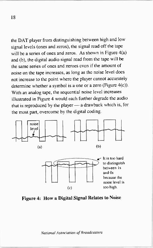
18
the DAT player from distinguishing between high and low
signal levels (ones and zeros), the signal read off the tape
will be a series of ones and zeros. As shown in Figure 4(a)
and (b), the digital audio signal read from the tape will be
the same series of ones and zeroes even if the amount of
noise on the tape increases, as long as the noise level does
not increase to the point where the player cannot accurately
determine whether a symbol is a one or a zero (Figure 4(c)).
With an analog tape, the sequential noise level increases
illustrated in Figure 4 would each further degrade the audio
that is reproduced by the player- a drawback which is, for
the most part, overcome by the digital coding.
(a) (b)
--------------------------- - k It is too hard to distinguish between is and Os
because the noise level is
too high. (c)
Figure 4: How a Digital Signal Relates to Noise
National Association of Broadcasters
19
While digital audio tape offers improved audio
performance over analog tape, it is still subject to the same
wear and tear that plagues analog tape. This includes such
things as having the tape machine "eat" the tape due to
malfunctions with the tape turning mechanics in the
machine, or problems with the tape cassette itself. It also
includes stretching of the tape, which happens over time
and generally more often with longer tapes (i.e., ones that
have longer playing times)
Compact Disc Players
Compact discs (CDs) are, to date, the most reliable media
for storing digital information. The reason is simple - on
a compact disc, the digital information is permanently
etched, or carved, into the plastic that makes up the CD. It
cannot be erased by passing through a magnetic field like
the information on a recording tape can, and really the only
way to damage the information on a CD is to physically
damage the CD itself by breaking it or severely scratching
it. Small scratches on a CD are often not a problem for
most modern CD players used in broadcast facilities
because the players are able miss a few is and Os here and
there in the digitally recorded audio and still accurately
reconstruct the recorded music. They are able to do this
A Broadcast Engineering Tutorial for Non -Engineers

20
because the digital data on the CD actually contains more
digital bits than are necessary to encode the audio
information. These additional bits are added, in a specially
coded manner, to enable the CD player to accurately
determine what the correct value of a missing or damaged
piece of digital data is. This system of adding these
additional bits is called an error correction system. An
error correction system is only capable of fixing errors in
the data up to a certain point. If there are too many missing
or damaged pieces of data, even the error correction system
will fail and the CD will skip or stop playing.
The other thing that helps to make a CD so durable is the
fact that it is not subject to any wear and tear during the
playback process. A CD player reads information off of a
CD by shining a light (a laser) on it and analyzing the
reflections of this light that are caused by the CD. Because
there is never any mechanical contact between the laser and
the CD, there is no wear and tear on the CD. A magnetic
recording tape, on the other hand, is subject to a lot of wear
and tear because during both playback and recording it is
being dragged over the tape head.
Some CD players used in broadcast facilities have both
analog and digital outputs. If the station's audio system is
analog -based, then the analog outputs can be used to feed a
signal into the mixing board. If, on the other hand, the
National Association of Broadcasters

21
station's audio system is digitally -based, then the digital outputs can be used to feed information into the mixing board. In a digitally -based audio system, digital outputs
from a CD player are generally more desirable because they
allow the station to avoid installing an analog -to-digital (A/D) converter between the CD player output and the
mixing board input. This is advantageous because, in
general, every time an audio signal has to go through a
conversion process it is degraded to some small degree. So,
it is desirable to keep the number of conversions to a
minimum.
The Mixing Board
The heart of a radio studio - the thing that allows several
program sources to be fed simultaneously to the transmitter - is the mixing board, or console. A basic mixing board is
simply a device that has multiple signals being fed into it
from different program sources (such as a microphone, a
CD player, and a tape player). The mixing board allows its
operator to combine (mix) the signals from the various inputs to produce a single output signal that is a
combination of the various input signals. Figure 5
illustrates the basics of mixing board operation.
A Broadcast Engineering Tutorial for Non -Engineers

22
CD player 2
CD player 1
mic 2 mic
4
cart 1
cart 2
phone hybrid
. . 4
00 CO 00 00 00 00 CO 0e
0 0 0 0 0 0 0 0
network feed
board output
Figure 5: Illustration of a Basic Mixing Board Setup
The mixing board functions in a manner that is very similar
to a home stereo system. In a home stereo, various program
sources (such as a cassette deck, a CD player, and a
turntable) are connected to a single amplifier. The user
must then select which one of the sources to amplify at any
given time -a selection which is often made by choosing
a single button to press from a series of buttons on the front
panel of the amplifier. A mixing board also connects
several input sources to a single amplifier. The big
difference between a mixing board and a home stereo,
however, is that the mixing board allows the user to select
multiple input sources (simultaneously) -a selection
which is usually made by choosing one, or more, buttons to
press from a series of buttons on the front panel of the
mixing board.
National Association of Broadcasters

23
To illustrate the significance that the ability to mix multiple inputs plays in producing an on -air radio program, consider the sequence of events that occurs when a radio announcer introduces a song. The announcer talks into the microphone to describe the song that is about to be played. While the announcer is talking, the select switch on the mixing board for the microphone input is selected, and the microphone is "potted up." (The phrase "pot up" is derived from the name of the electronic device used to control the level of the selected signal in many mixing boards -a potentiometer, or variable resistor.) At the same time, the select switch for the device that will play the song (e.g., a
CD player) is also selected and potted up, though no audio is coming from the CD player because it has not yet been started. When the announcer is finished introducing the song, the start button for the CD player is pressed and the music begins playing. At this point, the select switch for the microphone is deselected, or turned off, and the mixing board is no longer mixing any signals - it is simply amplifying a single signal (the CD player).
The above is just one example of how a mixing board is
used to produce an on -air broadcast signal. There are many others using all different kinds of input sources, and even other scenarios involving the two input sources described above. For example, many radio stations believe it sounds
A Broadcast Engineering Tutorial for Non -Engineers

24
better to the listener when the music from the CD player is
actually started before the announcer has finished
introducing the song. This helps to insure that there is
absolutely no silence, or "dead air," between the
announcer's introduction and the actual start of the song.
The importance of the mixing board becomes apparent
when one considers what it would be like to introduce a
song, and begin playing the song, using a device like a
home stereo system that allows only one input to be
selected at a time. Using such a device, the announcer
would have to select the microphone, introduce the song,
then simultaneously deselect the microphone, select the CD
player and start the CD playing. Such a system would
certainly result in an on -air signal that sounds choppy and
unprofessional with lots of "clicks" and "pops."
Well, by now you should be comfortable with the image of
a mixing board as an extra fancy amplifier like the ones
used in many home stereo systems. The outputs of the
various audio -generating devices (CD players,
microphones, tape players, etc.) are connected to the inputs
of the mixing board, and the output of the mixing board is
sent to the studio monitors (speakers) and off to the
transmitter for broadcast.
National Association of Broadcasters
25
Telephone Hybrids
A telephone hybrid is a piece of equipment that converts incoming audio from a telephone line into a "line level" signal that can be fed into a mixing board, tape recorder, etc. It also converts a "line level" signal coming out of a
mixing board into an audio signal that can be fed over the phone line.
Telephone hybrids are essential pieces of equipment for stations that do a lot of on -air talking to people who have called in. The hybrid allows the DJ or talk show host to hear the caller through the mixing board without having to pick up a telephone handset, and it allows the caller to hear the DJ or talk show host speaking through the microphone connected to the mixing board. By using the hybrid, the broadcaster ensures that only the caller's voice is of "telephone quality," while the DJ or talk show host's voice remains of "broadcast quality."
Microphones, Headphones and Speakers
Microphones, headphones and speakers will all be covered together because they all perform very similar functions. Microphones convert sound waves created by human
A Broadcast Engineering Tutorial for Non -Engineers

26
voices, instruments, or other things, into electrical signals
which can be fed into a mixing board, or another electronic
device. Headphones and speakers take electrical signals
and convert them into sound waves which can be heard by
the human ear.
The electrical signal produced by a microphone is of a very
low level, and it needs to be fed into a microphone
preamplifier before it is mixed with other studio audio
signals. In most cases, the microphone preamplifier is
included inside the mixing board, so no additional
equipment is needed. Care must be taken to insure that
only microphones are connected to the microphone input on
a mixing board. Connecting a device with a high output
signal, such as a CD player, to the microphone input on a
mixing board will overload the mixing board input and
might cause damage.
While each different model of broadcast microphone is
designed a little bit differently, they all have generally
similar design principles. All microphones have a surface
that, when impacted by a sound wave, causes a
corresponding change in the properties of an electrical
circuit. To illustrate the design principles that apply to
broadcast microphones, let's consider the designs of three
different microphones that are commonly found in
National Association of Broadcasters
27
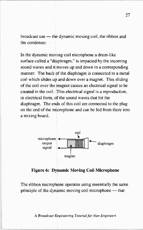
broadcast use - the dynamic moving coil, the ribbon and the condenser.
In the dynamic moving coil microphone a drum -like surface called a "diaphragm," is impacted by the incoming sound waves and it moves up and down in a corresponding manner. The back of the diaphragm is connected to a metal
coil which slides up and down over a magnet. This sliding
of the coil over the magnet causes an electrical signal to be
created in the coil. This electrical signal is a reproduction, in electrical form, of the sound waves that hit the
diaphragm. The ends of this coil are connected to the plug on the end of the microphone and can be fed from there into
a mixing board.
coil
microphone output signal
diaphragm
magnet
Figure 6: Dynamic Moving Coil Microphone
The ribbon microphone operates using essentially the same
principle of the dynamic moving coil microphone - that
A Broadcast Engineering Tutorial for Non -Engineers

28
an electrical signal will be produced in a wire which is
moving through a magnetic field. In the ribbon
microphone, a very thin piece of metal foil (the ribbon) is
suspended in a magnetic field in such a manner that
incoming sound waves impact the ribbon and cause it to
move back and forth in the magnetic field. This movement
of the ribbon within the magnetic field causes an electrical
signal to be created in the ribbon which is an electrical
reproduction of the sound waves that hit the ribbon. The
ends of the ribbon are connected to the plug on the end of
the microphone and can be fed from there into a mixing
board.
microphone output ribbon + magnet signal
Figure 7: Ribbon Microphone Design
The condenser microphone operates using a different
principle than a dynamic moving coil or ribbon
microphone. The operation of the condenser microphone is
based on the operation of a capacitor. A capacitor is an
National Association of Broadcasters

29
electronic device with two leads which allows electricity to
flow from one lead to the other at a varying rate, depending on how easily the material between the two leads allows
electricity to pass. In the condenser microphone, incoming sound waves strike a diaphragm which is situated in front
of a metal plate called the "back plate." Together, the
diaphragm and the back plate form a capacitor. The ability of the material between them (air) to allow electricity to
pass is dependent on how far apart they are. So, if
electricity is applied to the circuit in a condenser microphone, the flow of this electricity will vary in
proportion to the capacitance of the capacitor, which itself will vary in accordance with the sound waves hitting the
diaphragm. In this manner, an electrical signal is produced at the microphone output which is an electronic version of the incoming sound waves that are hitting the diaphragm. The main advantage of the condenser microphone is that
the capacitor circuit is much smaller and lighter than the
magnets used in the dynamic moving coil and ribbon microphones. For this reason, lapel, or clip -on
microphones are typically of the condenser type.
A Broadcast Engineering Tutorial for Non -Engineers

30
microphone 4
output signal
4
back plate
iI diaphragm
Figure 8: Condenser Microphone Design
A speaker, as one would imagine, operates in basically the
exact opposite manner of a microphone. In a speaker, an
electrical signal (of a much higher level than the one that
comes out of a microphone) is fed into a metal coil located
in a magnetic field. This metal coil is attached to a
lightweight surface called the - yes, you guessed it - diaphragm. The changing electrical signal in the coil
causes it to move back and forth in the magnetic field and,
because the coil is attached to the diaphragm, this causes
the diaphragm to move back and forth too. It is the
diaphragm's movement against the outside air that creates
the sound waves which can be heard by the human ear.
These soundwaves, of course, correspond to the electrical
signal that is fed to the speaker through the speaker wire.
National Association of Broadcasters

31
speaker input signal
magnet
coil
diaphragm
Figure 9: Typical Speaker Design
Headphones operate in a manner that is essentially the same
as the manner in which speakers operate, the main
difference being that the electrical signal levels fed into
headphones are not as strong as those that are fed into
speakers and, of course, the physical elements of a
headphone speaker are generally smaller than those of a
loudspeaker.
The unique thing about headphones, speakers and
microphones is that, no matter how many revolutionary
changes occur in broadcast equipment design, these devices will always operate in an essentially similar manner. While
it may be possible to convert all of the other audio signals
running around a broadcast facility to digital pulses - headphones, speakers and microphones will have to retain
their analog design because, at least as far as the
A Broadcast Engineering Tutorial for Non -Engineers

32
evolutionary eye can see, human voice and human hearing
will continue to be in analog form.
Computers
Well, speaking of converting the audio signals in a
broadcast facility to digital pulses, this is certainly the trend
in modern radio facilities. Nowadays, many radio stations
have most of their prerecorded music, commercials, etc.
stored on computer hard drives. The continually increasing
size of these hard drives, and their continually decreasing
cost (on a per megabyte basis), have made this possible.
There are many advantages to converting a radio station's
studio facilities to digital technology. One such advantage
is that digital recording material can generally overcome
noise in the audio path better than analog recording
material. Another advantage is that hard disk -based digital
recordings are easier to automate than analog tape
recordings because disk -based systems can be run by a
single computer program on a single machine, whereas
tape -based systems require the coordinated operation of
multiple machines through the use of cue tones. Yet
another advantage is that a computer system is subject to
less mechanical wear and tear than a tape -based system, so
it is more likely to have longer periods of time between
National Association of Broadcasters

33
mechanical malfunctions than a tape -based system. Also,
disk -based systems make log keeping much easier because
the computer that controls the system knows when it has
played a song, or a commercial, or whatever, and it can
automatically create and print its own program log.
When a radio station uses a disk -based audio system, there
are still two places where audio material must remain
analog. The first, as mentioned above, is at all of the
microphone inputs and speaker/headphone outputs. Human
voice and human hearing are still analog and therefore require analog mies and analog speakers and headphones.
The second is at the output of the transmitter. All of the
broadcast radio receivers that listeners are using today are
designed to receive analog radio (AM or FM)
transmissions. So, the final signal that comes out of the
transmitter must still be analog. Using equipment that is on
the market today, it is possible to have a DJ's voice
converted to digital immediately after leaving the
microphone and have it remain in digital form until after it
has been fed into the transmitter, which then produces an
analog output signal based on the digital input.
Some radio stations have converted partly to computer- they may have all of their commercials stored on a
computer, but still receive an analog satellite feed. In these
situations they will need to use a mixing board that is
A Broadcast Engineering Tutorial for Non -Engineers

34
equipped with both analog and digital inputs. There are
several such mixing boards on the market today. The
standard format for the digital input signals on these boards
is usually the AES/EBU digital format. "AES/EBU refers
to a standard format of digital bit transmission adopted by
the Audio Engineering Society and the European
Broadcasting Union.
Digital Audio Basics
There are three basic concepts that one needs to understand
in order to have a good basic understanding of digital
audio. These are resolution, sampling rate and bit rate.
The resolution of digital audio is the precision with which
the digital signal, at any particular instant in time, matches
the original analog material from which it was created.
Resolution, like many aspects of digital systems, is
measured in bits. The higher the number of bits (and thus
the resolution), the more accurately the digital signal
represents the original analog material. For example, 16 -bit
audio more precisely replicates original analog material
than does 8 -bit audio.
One of the keys to understanding digital resolution is
understanding the relationship between the number of bits
National Association of Broadcasters

35
of data in each digital sample and the amount of resolution that each sample has. On the surface it might appear that 16 -bit digital resolution is twice as good as 8 -bit resolution. This is not the case, however. In reality, 16 -bit resolution is
256 times as good as 8 -bit resolution.
To understand why this is so, let's consider an example. Let's imagine that we have a thermometer that can read temperatures in the range 0°-127°. If we only have one digital bit to represent the reading from the thermometer - that is, one bit of digital resolution - then a logical way to
digitally code the temperature from the thermometer would be to say that the digital bit is a zero whenever the
temperature is below 64° and it is one whenever the
temperature is at or above 64°. Clearly, this is not a very
accurate representation of the actual temperature reading from the thermometer.
If we have two digital bits to represent the reading from the
thermometer then we could assign a specific digital bit combination to four different temperature ranges. The bit combination '00' could represent temperatures below 32°.
The bit combination '01' could represent temperatures from 32° to 63°. The bit combination '10' could represent temperatures from 64° to 95°. And, the bit combination '11' could represent temperatures above 95°. Note that going from one bit of digital resolution to two bits of digital
A Broadcast Engineering Tutorial for Non -Engineers

36
resolution doubled the number of temperature ranges that
could be represented digitally, and thus doubled the
accuracy of the digital representation of the temperature
reading.
If we were to add yet another bit of digital resolution to this
system then temperature ranges could be represented
digitally as follows:
Digital Bit Combination Temperature Range
000 0°-15°
001 16°-31°
010 32°-47°
011 48°-63°
100 64°-79°
101 80°-95°
110 96°-111°
111 112°-127°
Going from two bits of digital resolution to three bits
doubled the accuracy of the digital representation of the
temperature reading once again.
Clearly, there is a pattern here. Each time a single bit is
added to the digital representation of the temperature
reading the accuracy with which the digital representation
National Association of Broadcasters

37
depicts the actual temperature doubles. This makes perfect
sense, when you think about it, because each digital bit has
only two possible values -0 and 1. So, when a single bit of digital resolution is added to a system all of the previous digital codes can still be used - let's say they represent the
same things they did before the new bit was added but now they represent them when the new bit is `0' - and an entire
new set of digital codes becomes available that is equal in
size to the one that existed before the new bit was added - in this example all of these new codes would be the ones
that existed before the new bit was added but now with the
new bit included and set to the value of `1.'
It should now be clear why 16 -bit digital audio represents the original analog material with 256 times more accuracy than 8 -bit digital audio. Following the pattern we just discussed, 9 -bit digital audio would be twice as accurate as
8 -bit audio, and 10 -bit audio would be twice as accurate as
9 -bit audio. Continuing all the way up to 16 -bit audio we
would find that the accuracy of 16 -bit audio is equal to the
accuracy of8-bit audio x2x2x2x2x2x2x2x2, which is another way of saying the accuracy of 16 -bit audio is equal to the accuracy of 8 -bit audio times 256.
A Broadcast Engineering Tutorial for Non -Engineers

38
I
Audio signal level
Sample point
time
Figure 10: A Digital Sample of an Analog Audio Signal
Whether the resolution of the digital sample is 8 -bit, 16 -bit
or whatever, each individual sample represents the level of
the audio signal at a particular instant in time. Sampling an
audio signal is a lot like sampling the thermometer in the
example we just discussed above. Probably the biggest
difference between sampling an audio signal and sampling
a temperature reading is that the audio signal changes value
much more rapidly. For this reason, the audio signal must
be sampled much more frequently than the thermometer in
order to provide an accurate digital representation of the
original information.
National Association of Broadcasters

39
Sampling Rate
The sampling rate is the rate at which digital samples are
made of the original material. The more often the original
material is sampled, the more accurately the digital
reproduction represents the original material.
Audio signal level
Sample points
ime - Figure 11: Periodic Digital Samples of an Analog
Signal
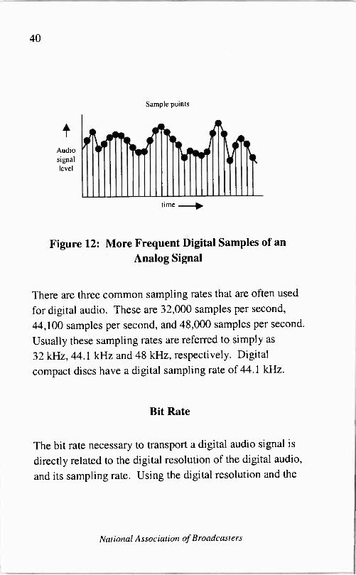
Figure 11 shows an analog signal being sampled at some
regular interval. Figure 12 shows the same analog signal
being sampled twice as often. As can be seen by
comparing these two figures, the more often a signal is
digitally sampled, the closer the series of resulting sample
points represents the original signal.
A Broadcast Engineering Tutorial for Non -Engineers
40
+ Audio signal level
Sample points
illlIIIIhuilIIliíinilIhiIh time _>,
Figure 12: More Frequent Digital Samples of an Analog Signal
There are three common sampling rates that are often used
for digital audio. These are 32,000 samples per second,
44,100 samples per second, and 48,000 samples per second.
Usually these sampling rates are referred to simply as
32 kHz, 44.1 kHz and 48 kHz, respectively. Digital
compact discs have a digital sampling rate of 44.1 kHz.
Bit Rate
The bit rate necessary to transport a digital audio signal is
directly related to the digital resolution of the digital audio,
and its sampling rate. Using the digital resolution and the
National Association of Broadcasters

sampling rate for compact discs, for example, we can calculate the bit rate necessary to transport CD audio.
CD digital resolution: x CD sampling rate:
CD bit rate per channel: x 2 stereo channels:
16 bits/sample/channel 44,100 samples/second 705,600 bits/second/channel 2
41
Total CD bit rate: 1,411,200 bits/second
There are eight bits in each byte of data on a computer disk. So, in order to store one second of compact disc stereo audio on a computer disk 1,411,200 = 8 = 176,400 bytes of disk space is required. A typical three minute long song would require 176,400 bytes x 180 seconds =
31.752 megabytes of disk space.
Compression
In order to conserve disk space, and also to make it possible to send digital audio signals through channels that are not capable of carrying all 1,411,200 bits per second from a
CD, a technique called compression is used. In order to
compress a digital audio signal some of the digital bits in
the audio signal are discarded, and the remaining bits can be encoded in a manner that reduces the total number of bits needed to transmit the audio.
A Broadcast Engineering Tutorial for Non -Engineers

42
The reason some bits can be discarded when compressing a
digital audio signal is that the audio they represent cannot
actually be heard by the typical listener. For example, if a
very loud tone is accompanied by a very quiet tone on a
slightly different audio frequency, in most cases the human
hearing system will not even recognize the existence of the
quiet tone. Therefore, the digital bits used to represent the
quieter tone can be discarded without perceptibly altering
the audio.
After all of the bits representing audio that generally cannot
be heard have been discarded, special digital coding
techniques can be used to further reduce the bit rate.
Because there are just about as many digital audio
compression systems as there are companies that make
digital audio equipment, there are many different ways that
coding techniques are used to reduce the data rate necessary
to transmit digital audio. It is beyond the scope of this
book to discuss all of these, but one general example of
how coding can be used to reduce bit rate will give you an
idea of how this is possible.
Let's say that the numerical values associated with
individual digital sample points in a segment of audio are:
5, 12, 7, 9, 5, 12, 7, 9, 5, 12, 7, 9, 5, 12, 7, 9, 5, 12, 7, 9
National Association of Broadcasters
43
It is possible to represent this series of values by simply
transmitting each individual value, and in fact this is how a
compact disc system works. It is also possible, however, to
simply transmit 5, 12, 7, 9 followed by the instruction
"repeat four more times." In this manner, the amount of
data necessary to transmit a long series of repetitious digital
values can be reduced.
The AES/EBU Digital Format
As mentioned earlier, the AES/EBU format is a
standardized format for transporting digital audio
information from place to place in a broadcast studio. It is
the most common standard used for this purpose in the
radio broadcasting industry.
Basically, in order to get digital audio information from one
place to another in a radio station studio, a stream of digital
bits must be carried - usually through a cable - from the
originating point to the receiving point. In order for the
device receiving the bits to understand which ones belong
where, a standardized format for transporting the bits must
be defined. This is what AES/EBU does.
A Broadcast Engineering Tutorial for Non -Engineers

44
In the AES/EBU format the stream of digital bits is
organized into 64 -bit long segments called frames. Each of these frames is further broken down into two sub -frames. Sub -frame 1 carries the digital audio information for audio channel 1, and sub -frame 2 carries the digital audio information for audio channel 2. In the vast majority of radio stations broadcasting music the two sub -frames correspond to the left and right channel of the stereo audio. The AES/EBU frame structure is illustrated in Figure 13.
I Device I sending
Frame 7 Frame 6 I
I
I Device receiving
AES/EBU Right Left Right Left I AES/EBU I bits data data data data I bits
I I
Figure 13: The AES/EBU Format
AES/EBU is not a file storage format. It is a standardized format for transporting digital audio from one point to
another. There are many different digital audio file storage formats, almost as many as there are manufacturers of digital audio storage equipment. Typically, when a digital
audio file is retrieved from a hard disk and sent, say, to a
mixing board, the playback device (the hard disk -based system) reads the file from the disk, formats it into an
AES/EBU data stream, and sends it out through a cable to
National Association of Broadcasters

45
the mixing board. The mixing board then receives the
digital audio through an AES/EBU-compliant input port.
Of course, in order to make use of the AES/EBU format,
the sending device must be capable of sending data in this
format and the receiving device must be able to receive this
format.
Whether a radio station is using a hard disk -based system,
or a completely analog studio system, after the audio
program material leaves the mixing board, and before it is
delivered to the transmitter, there are several important
pieces of equipment that it travels through. This equipment
can be broken down into three categories: distribution
amplifiers and servers, audio processing equipment and
Emergency Alert System (EAS) equipment.
Distribution Amplifiers and Servers
Distribution amplifiers (or DAs, as they are often referred
to) are relatively simple pieces of equipment which take an
electronic signal and distribute it to several places. They
are a necessity in an analog broadcast studio because a
particular signal will generally only come out of a mixing
board via one particular output connection and this single
connection, by itself, cannot be used to feed multiple pieces
of equipment without harming the output signal or, worse,
damaging the equipment.
A Broadcast Engineering Tutorial for Non -Engineers

46
As an example of why a DA is needed, consider a typical radio studio setup where the DJ talks on the air to people who have called in over the phone, and records some of these conversations for later rebroadcast. In this situation, the output of the mixing board needs to be fed through a
telephone hybrid into the telephone line so that the caller can hear what is being transmitted over the air through the phone line. In addition, the output of the mixing board needs to be fed into a recording device so that the conversation between the DJ and the caller can be recorded. Finally, the output of the mixing board also needs to be fed to the transmitter for broadcast over the air. The function of the DA in this scenario is to take the single output signal from the board as an input and resend it, at its full original strength, to all three locations.
DAs can also be used to feed the output of a mixing board in one studio into the input channel of a mixing board in
another studio. Or, they can be used to feed multiple recording devices (such as a cart recorder, a reel-to-reel recorder and a cassette recorder) in a single studio.
A studio that has been completely converted to a hard disk - based digital format will need to have the computer equivalent of a DA - called a server - for the same general reasons that a DA is needed in an analog studio.
National Association of Broadcasters

47
Servers are the devices that allow, for example, everyone in
an office to share a single copy of a word processing
program over a computer network. Similarly, they can also
allow multiple recording devices to share a single hard disk
version of a song in a radio studio.
The major difference between a server and a DA (other
than the fact that the server receives and sends digital
computer signals and the DA receives and sends analog
audio signals) is that the server is also a storage device.
Songs, commercials, newscasts and all other types of audio
segments used in a broadcast facility can be stored on a
server for later recall by whatever playback device wants to
use them. In addition, the server can be used for "live"
retransmission of a digital signal as it receives the signal. A
DA, on the other hand, is only capable of sending out audio
that it is receiving.
Audio Processing Equipment
The purpose of audio processing equipment is to create a
"signature sound" for the radio station, or at least to take
the "plain old audio" that comes from the microphone, CD
player, tape machine, etc. and enhance it in order to make it
sound better. Audio processing is as much an art as it is an
engineering science. Some stations do a lot of it and
employ several different pieces of equipment in the process.
A Broadcast Engineering Tutorial for Non -Engineers

48
Other stations do less and might only have a single piece of processing equipment. Most stations, particularly commercial ones that are competing with other stations for listeners and advertising dollars, do at least a moderate amount of audio processing.
From an engineering standpoint, the purpose of audio processing is to maintain the level of energy in the station's audio to within a specified range. Usually, this is done on a
frequency band by frequency band basis. The best way to understand how it works is to imagine an equalizer similar to one you might have with your home stereo or car radio. An equalizer, as those familiar with them know, is designed to amplify, or suppress, the level of signal within particular portions of the audio frequency band. Increasing the level of higher frequency signals, or decreasing the level of lower frequency signals, will make the audio have more "treble." Decreasing the level of higher frequency signals, or increasing the level of lower frequency signals, will make the audio have more "bass." What sets typical broadcast processing equipment apart from a normal equalizer is that the amount of equalization performed by the broadcast processor is dynamic (i.e., it changes with time) and it is
usually a function of the program material.
Let's consider an example of how a broadcast audio processing system might work. For this example we will
National Association of Broadcasters
49
assume that the processing equipment works over three
different frequency bands -- low (bass), mid -range, and
high (treble). Let's say that the station using this equipment
wants the on -air signal to have as high a level (volume) as
possible in all three bands. In this situation, the processor
will be set to increase the signal level in each band.
In a home stereo system, increasing the signal level across
all frequencies is very simple - the level (volume) control
for each frequency is turned up. In a broadcast audio
processing system, however, things are a bit more
complicated. This is due largely to the fact that FCC rules
limit the level (volume) of the transmitted audio.
The volume of the transmitted audio is very important to
most stations. Although some will do it for other reasons,
the primary reason that most radio stations use audio
processing is to increase the loudness of their signals.
Many broadcasters believe that a signal which sounds
louder will be perceived by the listener as being stronger
and therefore better. The secret to making a broadcast
station sound loud is to increase the level of the softer
portions of the program material, and decrease the level of
the louder portions of the program material, to the point
where the output of the audio processing equipment is kept
at as constant a level as possible. The reason that keeping
the output level nearly constant is important is because the
A Broadcast Eaigineering Tutorial for Non -Engineers

50
radio station must remain in compliance with the FCC's modulation limits.
Modulation increases and decreases with the level of a
station's program material. The stronger (i.e. louder) the program material is when it is fed into the transmitter's exciter, the greater the modulation level of the transmitted signal. (See Part III for a description of the transmitter and the exciter.) In fact, the modulation level of a broadcast signal can basically be thought of as the volume level of the signal.
Generally speaking, the FCC sets a maximum limit on modulation for two reasons. First, it helps to insure that one broadcaster's signal does not interfere with another broadcaster's signal and, second, it helps to insure a
reasonably similar level of audio from all stations, providing a generally stable listening environment for the audience.
Let's get back to our example of making a radio station's signal sound as loud as possible. There are several pieces of equipment which are typically used in the processing process - namely equalizers, compressors/expanders, limiters and clippers. These pieces of equipment are generally installed in a station's air chain in the order shown in Figure 14.
National Association of Broadcasters

51
audio from mixing board
equalizer compressor / expander -1> limiter Fw
to transmitter
Figure 14: Processing Equipment in a Typical Air Chain
Although shown as separate pieces of equipment in Figure
14, the equalization and compression/expansion functions
are often performed by the same piece of equipment.
Equalization is needed to perform the actual boosting of the
signal level over the appropriate frequency range (in our
example, the entire frequency range). Compression is
needed to ensure that the boosted signal does not exceed
the FCC modulation limit. Expansion is needed to ensure
that low-level (quiet) signals, such as background noise and
electronic hiss, are suppressed and not amplified to the
point that they become annoying. A limiter is needed to
further suppress any peaks in the signal that still exceed the
A Broadcast Engineering Tutorial for Non -Engineers

52
FCC modulation limit after compression, and a clipper can "chop off" any excessive peaks that make it out of the limiter. Let's look at some pictures that illustrate what happens during each step in the audio processing process.
audio level
low band (bass)
FCC modulation limit
mid band high band (treble)
Figure 15: Unprocessed Audio
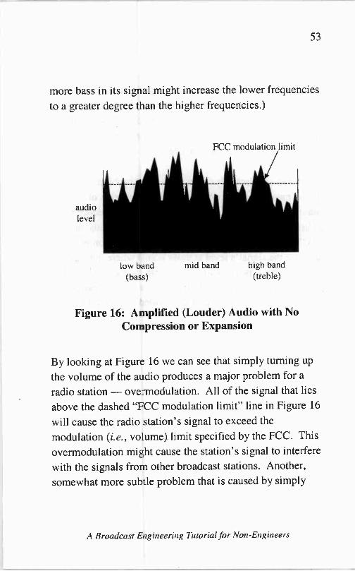
Figure 15 illustrates the signal level (volume) of an
unprocessed audio signal across all audio frequencies. The simplest and most intuitive way to increase the loudness of this signal is simply to increase the signal level (turn up the
volume) across all frequency bands using an equalizer. The signal that results from this action is illustrated in Figure 16. (A station that, for example, is interested in having
National Association of Broadcasters
53
more bass in its signal might increase the lower frequencies
to a greater degree than the higher frequencies.)
audio level
low band (bass)
FCC modulation limit
mid band high band (treble)
Figure 16: Amplified (Louder) Audio with No Compression or Expansion
By looking at Figure 16 we can see that simply turning up
the volume of the audio produces a major problem for a
radio station - overmodulation. All of the signal that lies
above the dashed "FCC modulation limit" line in Figure 16
will cause the radio station's signal to exceed the
modulation (i.e., volume) limit specified by the FCC. This
overmodulation might cause the station's signal to interfere
with the signals from other broadcast stations. Another,
somewhat more subtle problem that is caused by simply
A Broadcast Engineering Tutorial for Non -Engineers

54
turning up the volume of the entire signal is the
amplification of lower level (softer) signals which, in many
cases, are likely to be just background noise or electronic hiss. The "valleys" in the signal shown in Figure 16 are the
areas where this might be a problem.
In order to satisfactorily correct these two problems, the
station must do some compression and expansion of its
audio. Specifically, it must use compression to reduce the
audio signal's level at those points where it exceeds the
FCC's modulation limit, and it must use expansion to
decrease the signal's level at those points where the signal
is so low that it is likely to only contain background noise
or electronic hiss. An illustration of where compression
and expansion might be used is provided in Figure 17.
National Association of Broadcasters

55
FCC modulation compression occurs here
limit 1 + 1 +. +
audio level
FCC modulation
limit i_-
audio level
low band (bass)
low band (bass)
mid band
(a)
expansion occurs here
mid band
(b)
high band (treble)
high band (treble)
Figure 17: Amplified Audio with Compression and Expansion
A Broadcast Engineering Tutorial for Non -Engineers

56
It is worth repeating here that broadcast processing
equipment differs from a typical equalizer found in many
home stereo systems because of the ability of broadcast processing equipment to automatically adjust the amount of
compression, expansion, etc. that it is doing based on the
program material. A home equalizer will always suppress a
signal at, for example, 1 kHz, if it is set to do so, while a
broadcast processor will suppress a signal at 1 kHz only if
the signal is above the "threshold of compression." (The
threshold of compression is the signal level above which
the compressor will reduce the signal. Similarly, the
"threshold of expansion" is the signal level below which
the expander will reduce the signal.)
In addition to equalizers, compressors and expanders, there
are two other devices which are commonly found in
broadcast audio chains - limiters and clippers. Limiters
and clippers are both essentially compressors which, to
varying degrees, compress the audio signal more
aggressively than a "plain" compressor.
A limiter is typically used to take the peaks that still exist in
a signal after compression and knock them down further.
This is sometimes necessary when, after compression, a
signal still has peaks in it that are high enough to result in
overmodulation and a violation of FCC rules. A clipper is
generally used as a last resort to "chop off' any remaining
National Association of Broadcasters

57
peaks of overmodulation after the signal has passed through
both the compressor and the limiter. A clipper, if not used
correctly, can cause severe distortion to a signal because it
literally clips the peaks off - it does not "softly adjust" the
peaks like the compressor and limiter.
Although the configuration of processing equipment
described above is a typical one, it should be noted that
equalizers, compressors, expanders, limiters and clippers
can be used in a variety of configurations. As we said
earlier, audio processing is as much an art as it is an
engineering science, and some "artists" may prefer to use
only certain pieces of processing equipment.
Well, that about covers audio processing. As we mentioned
earlier, after a radio station's program material leaves the
main mixing board, it will generally travel through three
types of equipment before being fed to the transmitter.
These are distribution amplifiers or servers, audio
processing equipment (all of which we just covered) and
EAS equipment. Now, on to EAS equipment.
A Broadcast Engineering Tutorial for Non -Engineers

58
Emergency Alert System Equipment
The Emergency Alert System, or EAS, was first
implemented on January 1, 1997, replacing the old familiar
Emergency Broadcast System (EBS). The EAS is the
communications network that has been designed by the
Federal Government to allow the President to quickly and
efficiently speak to the entire nation in the event of a
national emergency.
Although the primary function of the EAS is to provide a
means for issuing national alerts, it has to date only been
used for its secondary purpose -- providing state and local
officials with a means of alerting local communities about
local emergencies like severe weather, chemical leaks, and
fires.
From an engineering standpoint, the way EAS operates is
relatively simple. As shown in Figure 18, an EAS
encoder/decoder is installed in a station's air chain in such
a way that it can interrupt the flow of normal programming to the transmitter in order to insert an emergency message.
(A station's "air chain" is the path that its on -air program
material follows from the program source to the
transmitter.)
National Association of Broadcasters

59
monitoring assignment #1 ssignment #2
program source from studio
Y EAS decoder
1
EAS encoder
I transmitter
Figure 18: EAS Equipment in a Radio Station Air Chain
The EAS decoder is constantly monitoring the
transmissions from the two sources that it has been
assigned to monitor. These two sources are usually either
other broadcast stations or NOAA Weather Radio. The
reason that the decoder is required to monitor two sources
is to help insure that it will still receive an alert message if
one of its monitoring assignments happens to be off the air.
If an alert is received by the EAS decoder, and it is a type of
alert that the station using the equipment has determined
should be on the air, the EAS encoder will break into the
station's air chain and put the alert on the air. Encoders can
be programmed to do this automatically, or they can be
A Broadcast Engineering Tutorial for Non -Engineers

60
programmed to require a person to manually interrupt the
station's programming.
Television Stations
The program material produced in a television studio is
basically the same as the program material produced in a
radio studio - except, of course, for the addition of a video
signal to accompany the audio. On the surface, adding a
video signal sounds like a relatively simple task - and, in
some respects, it is. However, the video signal does
significantly increase the complexity of a television studio
over that of a radio studio. The main reason for the added
complexity is the need to insure that the video and audio
signals in a television studio remain in synch, and that all of
the video switching equipment is timed correctly. We will
cover these two aspects of a television studio in greater
detail here, and we will build a solid foundation for
understanding video timing issues by learning about how a
television picture is created. We will not, however, go over
all major audio components of a television studio because
the audio equipment used in a television studio is generally
very similar to the audio equipment used in a radio studio
(although the typical TV studio setup usually involves the
use of mostly "live" audio sources while the typical radio
studio setup usually involves more prerecorded audio
National Association of Broadcasters
61
sources). For a review of studio audio you may read the preceding sections on radio station studio facilities.
Now, let's begin by learning about the standard video signal used in an analog television studio - NTSC video.
NTSC Video
"NTSC" refers to the National Television Systems Committee - the committee that, decades ago, designed the
standard for today's analog television transmissions. A
new, completely digital television standard has been
developed by the Advanced Television Systems Committee, or ATSC, and it will gradually be implemented in television stations in the years to come.
NTSC video signals are, in reality, a rapid-fire series of still
pictures that are projected on a television receiver at a rate
of 30 pictures per second. Each of these pictures is called a
"frame." This rapid-fire series of still pictures creates the
illusion that the picture on the TV is moving.
A Broadcast Engineering Tutorial for Non -Engineers

62
Figure 19: Series of Still Pictures that Create Illusion of Motion
Figure 19 provides a simple example of a series of still
pictures which might be used to create the illusion that a
ball is bouncing across the screen.
In the NTSC system, each video picture frame is painted on
the television screen, from top to bottom, one horizontal
line at a time. There are 525 horizontal lines in each frame
(483 of which form the actual picture), but they are not
painted in successive order (i.e., 1, 2, 3 ..., etc.). Instead,
all of the odd -numbered lines are painted first, followed by
all of the even -numbered lines. This process is called
interlacing.
National Association of Broadcasters

63
field A-1
.001""4 r.\ frame A
field A-2
Figure 20: Two Interlaced Fields for Each NTSC Frame
The two images that are created during the interlacing
process (the picture with only odd -numbered lines and the
picture with only even -numbered lines) are called "fields."
There are two fields for every frame, as illustrated in Figure
20. Since the frame rate is 30 pictures per second, the field
rate is 60 fields per second, or one field every 1160th of a
A Broadcast Engineering Tutorial for Non -Engineers

64
second. The odd- and even -numbered lines are interlaced
together to form the complete picture. Interlacing is used
because it helps to eliminate flickering of the TV screen.
How? Well, the best way to answer this is to look at what
would happen if interlacing were not used.
As we noted earlier, there are 30 frames of video per
second. This means that each individual line on the TV
screen is updated, or "refreshed," 30 times per second (this
is true in both interlaced and non -interlaced situations - or
at least it would be if there were such a thing as
non -interlaced NTSC video). If interlacing were not used,
then each picture frame would be painted on the screen,
from top to bottom, in its entirety, and would then be
followed by the next picture frame, and the next one, and so
on and so on. The effect this would have on the overall
picture is best illustrated by isolating two adjacent lines of
video on the TV screen. For our example, let's randomly
pick lines 137 and 138. On a non -interlaced screen lines
137 and 138 will be refreshed at essentially the same time.
(Line 138 will actually be refreshed a very tiny fraction of a
second after line 137, but this extremely small time
difference is not relevant as far as understanding the
difference between interlaced and non -interlaced screens is
concerned.) After lines 137 and 138 are refreshed, they are
refreshed again 1130`h of a second later. To the human eye,
National Association of Broadcasters

65
it appears as though the area on the screen encompassed by
lines 137 and 138 is being refreshed 30 times per second.
On an interlaced screen line 138 will be refreshed 1160`h of
a second after line 137 because the first field (the
odd -numbered lines) are refreshed during the first half of
each 1/30`h of a second frame, and the second field (the
even -numbered lines) are refreshed in the second half of
each frame. Because, at a normal viewing distance, the
human eye cannot distinguish between lines 137 and 138,
the net effect of the interlacing is to make it appear that
both lines are being refreshed 60 times per second - when
in fact each individual line is only being refreshed 30 times
per second.
The refresh rate is very important because, if the rate is too
low, each line on the screen will have noticeably started to
fade from the screen before it is refreshed, causing the
screen to flicker. Increasing the refresh rate (or, in the case
of NTSC interlacing, creating the appearance of an
increased refresh rate) helps to reduce flickering.
To review, in an interlaced NTSC television picture, each
of the lines in the picture is still refreshed 30 times every
second. However, to the human eye, the interlacing makes
it appear as though the screen is being updated twice as
often, or 60 times every second. What makes this possible
A Broadcast Engineering Tutorial for Non -Engineers
66
is the fact that the human eye generally cannot perceive the
fact that two adjacent lines on the video screen are being
refreshed at different times when there is only a period of 1/60`" of a second between their respective refresh times.
Because the eye cannot perceive the difference in refresh
times, each half -screen refresh (odd- or even -numbered
lines) has nearly the same effect on the viewer as a full
screen refresh, the effect is to create the appearance that the
full screen is being refreshed twice as often, or 60 times per
second. Increasing the apparent refresh rate causes screen
flicker to be reduced.
Readers who are familiar with computer equipment will
know that non -interlaced monitors are the viewing screens
of choice for many computer users. You may be asking
yourself then, if interlaced video is so good, why do so
many computers have non -interlaced screens? Well, the
answer turns out to be cost. In a computer system, it is less
expensive to implement a non -interlaced display than it is
to implement an interlaced display. This is because, in a
computer system that uses a non -interlaced display, a single
block of memory can store the information for the entire
screen, and the entire contents of that block of memory can
be transferred to the screen 75 times every second (or more,
or less, depending on what the video refresh rate is). In an
interlaced system, on the other hand, additional memory
and/or control circuitry would be necessary because the
National Association of Broadcasters

67
odd -numbered lines would have to be painted first,
followed by the even -numbered lines. There would either
have to be two separate blocks of video memory (one for
odd -numbered lines and one for even -numbered lines) or a
more complex procedure for only transferring half of the
lines in a single block of memory to the screen followed by
the other half. In either case, the cost of implementing an
interlaced system is greater than the cost of implementing a
non -interlaced system when it comes to the number of
memory chips and circuitry required.
Computer makers have the option of producing non -
interlaced systems because the amount of video information
that can be transferred from a computer to its monitor is
large enough that a full -screen, non -interlaced refresh rate
can be achieved which does not result in screen flicker. In
other words, an entire computer screen (both odd and even
lines) can be updated at a typical rate of about 75 times per
second because enough video information, at a high enough
rate, can be fed from the computer to the monitor to make
this happen. In the NTSC television channel, on the other
hand, only 30 frames worth of video information can be fed
to the screen every second. This is because the amount of
video that can be sent to an NTSC television screen is
restricted by the size of the NTSC television channel, which
is 6 MHz wide. It is also restricted by the fact that 30
frames of video per second was pretty much the best that
A Broadcast Engineering Tutorial for Non -Engineers

68
available technology could do in a 6 MHz channel when the
NTSC standard was defined.
Before we go on to discuss the importance of video timing and audio -video synchronization in a television studio, let's finish our discussion about the basics of NTSC video by
learning about methods for including additional, non -video information in an NTSC video signal.
The Horizontal Blanking Interval
As we have already learned, there are 525 horizontal lines
of information in an NTSC video signal, 483 of which carry
the actual picture information. The lines that carry the
picture information are painted on the screen in a top -to -
bottom manner with all of the odd -numbered lines being
painted first followed by all of the even -numbered lines.
The electron gun inside the cathode ray tube (CRT) is the
device inside the television receiver that actually paints the
video picture. It shoots a beam of electrons at the back of the video screen in a left -to -right, top -to -bottom manner (odd -numbered lines first, even -numbered lines second).
Each time the electron gun's beam reaches the right edge of the picture screen it must stop and then move back to the
left-hand side of the screen in order to start painting the
National Association of Broadcasters
69
next line. If the electron gun were to remain on during this
entire process, it would end up painting a line of video on
the screen and then immediately painting a streak right
below the line of video while it retraced its path back to the
left-hand side of the screen. In order to prevent this from
happening, the electron gun is turned off after it reaches the
far right-hand side of the screen and it remains off until the
beam is positioned back on the left-hand side of the screen
and ready to begin painting the next horizontal line. The
period when the electron gun is off while it is retracing its
route over the screen is called the horizontal blanking
interval. The horizontal blanking interval is a very short
period of time, significantly less than it takes to actually
paint one horizontal line of video on the screen.
line of video is painted - ti
4
beam shuts r off, then returns to
a- left side (horizontal
blanking interval)
Figure 21: The Horizontal Blanking Interval
A Broadcast Engineering Tutorial for Non -Engineers

70
The Vertical Blanking Interval
As one would expect, the same concern about putting a
streak on the screen must be addressed when the electron
beam finishes painting the bottom line of video and needs
to be repositioned to the top left-hand corner of the screen.
During this operation, the beam is once again turned off while it is retargeted toward the upper left corner. This
period when the beam is turned off is called - yes, you
guessed it - the vertical blanking interval. It takes a lot
longer for the electron beam to reset itself from the bottom right-hand corner of the screen to the top left-hand corner than it does to reset itself from the right-hand side of one
line to the left-hand side of the next. While the horizontal
blanking interval is significantly shorter than the time it
takes to paint one horizontal line, the vertical blanking
interval lasts for about the same amount of time needed to
paint 21 horizontal lines on the screen. Because of the
additional time in the vertical blanking interval, it is much
easier to use it to transmit auxiliary information than it is to
use the horizontal blanking interval.
National Association of Broadcasters

first line of information in next field
last line of information
in a field 1
..
71
beam shuts off, then
returns to top left
corner of screen
(vertical blanking interval)
Figure 22: The Vertical Blanking Interval
Because the vertical blanking interval lasts essentially as
long as the time it takes to paint 21 horizontal lines on the
screen, the time during the vertical blanking interval is
referred to as if it were horizontal lines on the screen. It is
customary, for example, to refer to "line 21 of the vertical
blanking interval" or "line 19 of the vertical blanking
interval."
One thing that leads to confusion for some people is the
fact that all 21 lines of the vertical blanking interval are
transmitted before each field. (Remember, afield is only
half of the lines in a frame - either the odd or even ones.)
This makes sense, if you think about it, because it is at the
end of each field that the electron beam must reset itself
from the bottom right-hand corner of the screen to the top
A Broadcast Engineering Tutorial for Non -Engineers

72
left-hand corner. The reason this leads to confusion is that
each field consists of only half the horizontal lines on the
screen (odd or even), but each vertical blanking interval
(VBI) contains all of its 21 lines - not just odd or even
numbered VBI lines.
The Federal Communications Commission has specified
what type of auxiliary information can be transmitted on
various VBI lines. A summary of the FCC's requirements
is as follows:
Lines 1-9 Vertical synchronization information only
(needed to insure that the TV receiver knows this is the end of one field of video
and the start of the next)
Lines 10-18 Test, cue and control signals; telecommunications (or other applications with prior FCC approval) - e.g., control
signals could be sent from a network to local
affiliates to alert the affiliates to the fact that
a local commercial break is coming
Line 19 Ghost canceling signal only
(used by receivers equipped with ghost -
canceling circuitry to reduce "ghosts"
caused by the simultaneous reception of
multiple versions of the same TV signal - usually due to signal reflections)
National Association of Broadcasters

73
Line 20 Test, cue and control signals; telecommunications (or other applications with prior FCC approval) (see above)
Line 21 Closed captioning only
(descriptive text used by hearing impaired
persons)
ATSC Video
ATSC is the Advanced Television Systems Committee, which adopted a standard for digital television transmission
in 1995. This standard was subsequently adopted (with the
exception of the video formats portion) by the Federal
Communications Commission in 1996.
Like NTSC video signals, ATSC video signals are a rapid-
fire series of still pictures that are displayed by a television
receiver. That is about as far as the similarity goes,
however. ATSC signals can have different aspect ratios
than NTSC signals. They also have more, or about the
same number of horizontal lines per screen (whether it is
more or about the same is a choice available to the
broadcaster transmitting the ATSC signal). The rate at
which ATSC pictures are painted on the screen can also
differ from NTSC. And, ATSC video is transmitted in
A Broadcast Engineering Tutorial for Non -Engineers

74
blocks of compressed digital data, instead of in a -
continuous stream of analog data like the NTSC signal.
Finally, while the audio that accompanies an NTSC video
signal is essentially of the same technical format as the
audio from an FM radio station, the digital audio that
accompanies ATSC video is of a dramatically different
format from that used in radio broadcasting.
The ATSC signal is a stream of digital bits that is created
by an ATSC encoder and delivered to the television
station's transmitter at a rate of 19.39 million bits per
second (megabits per second). In order to appreciate how
fast this data rate is, consider the fact that a 56K modem for
a personal computer - generally considered the state of the
art today - has a data rate of only 0.056 megabits per
second. Thus, it would take nearly 350 56K modems to
handle the same amount of data that a single piece of ATSC
equipment can handle.
The signal that is actually routed around the television
studio and used for editing, recording, etc., can be one of
various video formats - and in fact many stations will likely
continue to use their NTSC equipment in the studio through
the early stages of digital television implementation. The
only requirement is that, in order to broadcast an ATSC
digital television signal, the station must have an ATSC
National Association of Broadcasters

75
encoder that is capable of encoding the signal format used
by the station's studio equipment.
The bits in the ATSC data stream are organized into
188 -byte blocks. The first byte of each block is used for
synchronization. This synchronization byte is needed to
clearly identify when a new block of data is beginning so
that the device receiving the data stream can properly
decode the data. Because one of the 188 bytes in each
block of data is dedicated to synchronization, there are only
187 -bytes per block available for actual video, audio and/or
ancillary data. The data rate of the actual video, audio
and/or ancillary data (often referred to as the payload data
rate) is 187/188 x 19.39 megabits per second, or
19.28 megabits per second.
synch byte
synch byte
synch byte
187 bytes of audio, 187 bytes of audio, 187 bytes of audio,
video and/or video and/or video and/or
ancillary data ancillary data ancillary data
Figure 23: The ATSC Data Stream
A Broadcast Engineering Tutorial for Non -Engineers

76
It is worth mentioning here that, although the information data rate of an ATSC signal is 19.39 megabits per second, the data rate of the digital television signal that is broadcast from a DTV transmitter site is much higher. This is
because additional data must be added at the transmission point in order to have enough error -correcting information to fix all of the damage caused to the digital signal as it
travels from the transmitter to the receiver. We will discuss
this more in Part III.
So, we now know how the ATSC data stream is formatted,
but what exactly is the information it is carrying? We will
explore that next.
Pixels
Chances are that you are already familiar with the concept
of a pixel. A pixel is a dot on a video screen, the smallest component of a video image. Pixels have become very
familiar to most computer users because the resolution of a
computer screen - i.e. the level of detail on the screen - is
usually defined in terms of pixels. Some typical computer screen resolutions defined in terms of pixels (horizontal and
vertical) are 640x480, 800x600 and 1024x768. The more pixels there are on the screen, given a fixed monitor size,
the more detailed or cleaner the image.
National Association of Broadcasters

77
The pixel is also the smallest component of an ATSC video
image. One of the high -definition ATSC video formats
has, from top to bottom, 1080 horizontal lines across the
screen. Each of these lines contains 1920 pixels. You will
recall from the section on NTSC video that the analog
television system being phased out in the United States has
only 525 lines per frame of video, and only 483 of these
contain viewable information. It is easy to understand
where the term high -definition television comes from when
you consider that a 1080 -line ATSC video frame has more
than double the number of horizontal lines of an NTSC
video frame.
4:3 16:9
NTSC oir ATSC ATSC
video image video image
Figure 24: 4:3 and 16:9 Aspect Ratios
There are several reasons that the two aspect ratios, 4:3 and
16:9, were selected for the ATSC standard. The 4:3 aspect
A Broadcast Engineering Tutorial for Non -Engineers

78
ratio was selected because it is the same aspect ratio used in
NTSC video, and there are a tremendous number of archived television programs in this format. The 16:9
aspect ratio was selected because it had already gained acceptance in other parts of the world as a compromise between the motion picture industry's desire for as wide a
screen as possible and the manufacturing costs of tube -based displays. About 80% of motion pictures are
shot at an aspect ratio of 1.85:1, which easily fits into a
16:9 screen with negligible use of letterboxing. (Letterboxing is a technique used to fit a video image onto a
television screen, without altering the aspect ratio of the original video image, by blacking out the top and bottom portions of the television screen.)
Each line in an NTSC video picture is a continuous stream of video information. Each line in an ATSC video picture is a series of discrete pixels. Because an ATSC video image is a series of discrete pixels, it can be manipulated by
computer circuitry at both the transmitter and the receiver more easily. Most importantly, video can be compressed at
the transmitter and decompressed at the receiver - this is
what makes digital television (DTV) using the ATSC standard possible.
National Association of Broadcasters

79
Compression
Compression is an extremely important aspect of the ATSC
video signal. In fact, as we just noted above, compression
is so important to ATSC video that, without it,
high -definition digital television would not be practical.
Put quite simply, to compress digital video means to take a
complete digital video signal, throw away unneeded parts
of it, and encode the remaining parts in a manner that
reduces the total amount of data required to store or
transmit the video. The process of discarding unneeded
components of the video signal, and encoding what
remains, is performed by a computer program called a
compression algorithm. "Algorithm" in this context is just
another way of saying "computer program."
The compression algorithm used for ATSC video is very
complex. Because it is not necessary to understand exactly
how it works in order to have a good understanding of
ATSC video we will not try to explain it here. Such an
explanation would likely require an entire book by itself.
We will, however, briefly discuss two basic principles of
compression in order to provide a general understanding of
how it is possible to reduce the amount of data in a video
signal without noticeably degrading the video.
A Broadcast Engineering Tutorial for Non -Engineers

80
The first basic principle of compression is the elimination of unneeded data. Basically, data is unneeded if, once discarded, the viewer cannot tell that it is gone. How can data be discarded without the viewer noticing? Well, the secret lies in the fact that digital video cameras and their associated recording equipment are capable of "seeing" more than the human visual system can detect. For example, a digital video recording system is capable of recording the amount of brightness and the amount of color in a picture very accurately. It turns out, however, that the human visual system is generally less sensitive to the amount of color in a picture than the amount of brightness (i.e., certain changes in brightness are easier for the human eye to detect than certain changes in color). For this reason, some of the most detailed color information in a digital video picture can be discarded without changing what human viewers will actually see.
The second basic principle of compression is the efficient coding of the remaining video. The best way to understand how video data can be coded in a more efficient manner so
as to require less data overall is to use an example. Let's assume that a particular video image has a red horizontal
line 100 pixels in length extending across the screen. The uncompressed video data for this image might include instructions like this:
National Association of Broadcasters
81
print pixel 1 in red
print pixel 2 in red print pixel 3 in red
print pixel 98 in red
print pixel 99 in red
print pixel 100 in red
However, the compressed video data for this image might
include instructions like this:
print red pixel repeat 99 more times
While the type of compression that is used in ATSC video
is much more sophisticated than this simplistic example,
one can see from this example how it is possible to more
efficiently code raw video data in a manner that requires
less data overall to transmit the video image but, at the
same time, does not degrade the video image.
A Broadcast Engineering Tutorial for Non -Engineers
82
Frames
As noted earlier, ATSC video signals, like NTSC video signals, are a rapid-fire series of still pictures that are
projected on a television receiver. Each of these still
pictures is called a frame.
There is a major difference between NTSC video frames and ATSC video frames. In NTSC video each frame is,
from a technical design standpoint, identical to the one
before it and the one after it. That is to say, although the
video data (the picture) carried in the frame changes from
frame to frame, the design of each frame itself remains constant. The odd -numbered horizontal lines of video are
transmitted first, in successive order, followed by the even -
numbered lines. This format remains constant for all
frames in every NTSC video stream.
In the digital ATSC video stream there are three distinct frame types used to carry video: intracoded frames, predictive coded frames and bi -directionally predictive coded frames. These are generally referred to simply as
I -frames, P -frames and B -frames. The reason there are
three different frame types for ATSC digital video is that
using three different types of frame permits further compression of the video signal, thus reducing the amount
National Association of Broadcasters

83
of disk space needed to store it, and the amount of radio
spectrum needed to transmit it.
Figure 25: I -Frame
An I -frame can stand by itself, without accompanying
P -frames or B -frames. It is intracoded, which means that
the only data compression coding done to it is within its
own borders. Thus, when an ATCS video stream is
decoded, an I -frame can be decoded by looking only at the
data within itself. Intra is a Latin prefix that means
"within."
A Broadcast Engineering Tutorial for Non -Engineers

84
I -frame used to predict P -frame
Figure 26: I -Frame Followed by P -Frame
A P -frame cannot stand by itself. At least some, and
possibly all, of the picture in a P -frame must be predicted
from the most recent I -frame or P -frame. Many video
images lend themselves to this kind of prediction because
they are either static (a still picture), or they involve some
form of predictable motion. The advantage of a P -frame is
that it involves more compression than an I -frame (both
intra- and interframe coding) and therefore helps to reduce
the data rate necessary for transmitting an ATSC signal.
The disadvantage of a P -frame is that it cannot be used, by
National Association of Broadcasters

85
itself, to create a "freeze frame" image of the segment of
video that it represents.
B -frame predicted
from I -frame and P- frame
1 -li amc
.., IIII
B -frame
nu ++seu
'jaIIIl
P -frame
Figure 27: A B -Frame between an I -Frame and a
P -Frame
A Broadcast Engineering Tutorial for Non -Engineers

86
Like a P -frame, a B -frame cannot stand by itself. Unlike a
P -frame, however, a B -frame is predicted from two other frames, a previous I -frame or P -frame, and a subsequent I -frame or P -frame. It is a little bit tricky to understand what is happening with a B -frame because it seems a bit
counter -intuitive that a particular frame in a video stream
could be predicted, in part, from a frame that has not even
made it to the screen yet. That is, how can something be
predicted based on something that has not even occurred yet?
Well, the trick to understanding B -frames is to understand that the digital ATSC video stream does not arrive at a
television set and immediately get dumped onto the screen.
The digital ATSC data is temporarily stored, processed, and
then forwarded to the screen. The "store and forward" process is called buffering, and it is a common practice in
digital transmission. While the video data is temporarily stored in the receiver, the computer circuitry in the receiver has an opportunity to process or manipulate it.
The reason that the data must be temporarily stored and processed is that it needs to be decompressed. You will
recall from the discussion earlier about compression that,
during the transmission process, portions of the original
video stream are discarded, and the remaining portions
National Association of Broadcasters

87
encoded, in a manner that reduces the total amount of data
needed to transmit the signal. Well, although the
compressed television signal that is transmitted over the air
contains enough information to recreate a video image on
the television screen that appears, to the typical viewer, to
be identical to the original video, the compressed signal
itself does not carry all of the necessary video data. Instead,
it carries instructions that enable the computer circuits
inside a DTV receiver to recreate the image.
This is a good place to point out that the buffering which
occurs inside a television receiver is the reason that there is
a brief delay between the instant that the viewer selects a
new channel and the instant that the new channel appears
on the screen. Also contributing to this delay is the fact
that, in order to begin decoding video from a new channel,
the decoder must wait for the next I -frame to be transmitted
on that channel. This is because the I -frame is the only one
that can stand by itself without any previous frames to use
for prediction - so in order to begin decoding a new stream
of video a receiver must start with an I -frame.
So, back to the B -frame and its place in this process. As
noted above, a B -frame is predicted from a previous
I -frame or P -frame and a subsequent I -frame or P -frame.
For the receiver to be able to construct a B -frame, the two
frames from which it is predicted must be transmitted
A Broadcast Engineering Tutorial for Non -Engineers

88
before the B -frame. So, if three consecutive frames of video at the television studio have been encoded in such a
manner that the first is an I -frame, the second is a B -frame and the third in a P -frame, the I -frame will be transmitted first, followed by the P -frame and then the B -frame. The
receiver will then have the opportunity to receive and store
the information for both the I -frame and the P -frame
(frames 1 and 3) before it has to decode the B -frame
(frame 2).
Frame Rate
Another major difference between ATSC video and NTSC video is that ATSC video may be transmitted at different frame rates. Recall from the discussion about NTSC video
that the only frame rate available under that system is
30 frames per second. The limited size of the television channel (i.e., the limited amount of spectrum available in
which to transmit the video) basically prevented the NTSC
standard from using any frame rates higher than 30 frames
per second. Higher frame rates would have required more
information to be transmitted over the air, which would
have required wider channels.
Because the ATSC standard includes a method for
compressing the transmitted video, more video information
National Association of Broadcasters

89
can be squeezed into the same amount of spectrum. This
provides several opportunities that were not available with
the NTSC standard. Specifically, it allows bigger pictures
to be transmitted (hence the availability of wide-screen
pictures); higher frame rates (more pictures per second) to
be transmitted; and/or multiple video streams to be
transmitted. We discussed the wide-screen aspect of ATSC
video earlier, and we will get to its multiple video stream
capability shortly. For now, we are focused on the frame
rate.
While the ATSC video signal is capable of being transmitted at a higher frame rate than NTSC video, it does
not have to be transmitted at a higher frame rate. There are
three standard frame rates for ATSC video - 24, 30 and 60
frames per second. Twenty-four frames per second is a rate
commonly used for film. Thirty frames per second is, of
course, the rate used for NTSC video, and 60 frames per
second is a faster frame rate that further reduces screen
flicker by refreshing the video screen more often. The
more frames per second that are transmitted, the more data
that is needed to transmit, or store, the video signal.
At least for the duration of the transition to digital
television the vast majority of television studios will be
using frame rates of 1000/1001 times the integer frame
rates listed above. They will be doing this to facilitate
A Broadcast Engineering Tutorial for Non -Engineers
90
conversion of NTSC pictures to ATSC (the precise frame
rate of NTSC pictures is 59.94 frames per second), and in
order to avoid problems associated with having multiple timing signals in a single facility.
Interlacing
Each of the three frame rates in ATSC video can be
employed in either an interlaced or non -interlaced manner.
It should be noted, however, that 60 frame -per -second
video (interlaced or non -interlaced) is not available in
the1920 x 1080 format, and 30 frame -per -second video is
not available in interlaced form for the 1280 x 720 format.
The reasons for this are discussed a bit later. Non -
interlaced video is often called progressive video because
each horizontal line is painted on the screen in order, from
top to bottom, in a progressive manner.
We discussed what it means for video to be interlaced in
the section on NTSC video, so we will not repeat it hear.
The choice of whether to use interlaced video or non -
interlaced video at a broadcast facility is really one of personal preference. There are many people who will argue
that interlaced video is preferable in many applications, and
there are many other people who will argue that progressive
video is preferable.
National Association of Broadcasters

91
Multicasting
Combining several different video programs together and
broadcasting them over the same television channel is
called multicasting. This is something that was not
possible with NTSC video in the 6 MHz -wide television
channels in the United States. With digital ATSC video,
however, it is possible to fit several smaller, lower frame
rate video programs into the same television channel that
can transmit a single, wide-screen, high definition program.
The number of different video programs that can be
squeezed into a television channel is dependent on the data
rate necessary for each individual program.
While the interlaced versus progressive aspect of an ATSC
video image is an important aspect of the image, it does not
have much of an impact on the digital data rate necessary to
transmit the image (i.e. 30 frame per second video requires
essentially the same data rate whether it is transmitted in
interlaced or progressive mode). This data rate is mostly
dependent on the frame rate and the screen size of the
video, as well as the subject matter of the video. All else
being equal, larger screen sizes require higher data rates,
higher frame rates require higher data rates, and video with
A Broadcast Engineering Tutorial for Non -Engineers

92
lots of motion and/or scene changes in it also requires higher data rates.
The basic video formats (screen sizes and frame rates) that can be used in ATSC video are listed in Table 1.
Table 1: ATSC Video Formats
Screen Size in Pixels Aspect Ratio Frame Rate
1920 x 1080 16:9 24P 3013 30I
1280 x 720 16:9 24P 30P 601)
704 x 480 16:9 24P 30P 30I 6013
704 x 480 4:3 24P 30P 30I 60P
640 x 480 4:3 24P 3013 30I 60P
The reason that there is no 1920 x 1080 format at 60 frames per second is that the high data rate needed to transmit this format could not be achieved within the limited amount of bandwidth (6 MHz) available for television broadcasting in
the United States. Because this format has the largest
screen size, and because transmitting 60 frames per second requires essentially double the data rate necessary to
transmit 30 frames per second, this combination of screen
size and frame rate would require a higher transmission data rate than any of the others.
National Association of Broadcasters

93
The reason that the 1280 x 720 format does not include an
interlaced version at 30 frames per second is that, when the
ATSC standard was developed, this particular format was
seen as a "progressive scan only" format.
Because video transmitted in the 1920 x 1080 format at
30 frames per second uses almost all of the capacity of the
6 MHz -wide DTV channel, when this format is transmitted
it generally cannot be accompanied by any other video
feeds over the same channel. On the other hand, video
transmitted in the 640 x 480 format at 24 frames per second
uses the least amount of channel capacity of all the ATSC
formats. When this format is used it is possible to transmit
multiple video feeds over the same 6 MHz wide channel.
There is no specific formula that can be used to specify
exactly how many video feeds of various formats can be
transmitted over the same channel. This is because the data
rate needed to transmit a particular format is not a constant
number. The reason it is not a constant number is that the
amount of compression that can be performed on a data
stream is dependent on the content of the video
programming. Video that is generally static, such as a still
picture of a station's logo, can be compressed much farther
than video that has a lot of scene changes in it. As we
noted earlier when talking about frames, the way ATSC
video is compressed involves, in part, sending only
A Broadcast Engineering Tutorial for Non -Engineers

94
information about how one frame differs from another
rather than complete information for every frame. So,
because successive frames of a still picture video image will have no differences between them, very little
information needs to be transmitted to explain to the
receiver the difference between one frame and the next.
One thing that is very important to keep in mind when
considering the multiplexing of several video programs is
that the total data rate for all of the mutiplexed video
streams added together must not exceed the total data rate
available in the DTV channel at any time. For example, a
single DTV channel might be capable of carrying four different programs most of the time, but if these programs
contain commercials that have a lot of motion and scene
changes in them it might be the case that the single DTV
channel cannot handle a commercial on every single channel at the same time. Clearly, if the commercials will
all be run at the same point in time, this could cause a
problem. The program might appear fine to the viewer
until the commercials come on at which time the video
would become distorted due to a lack of available capacity for transmitting all four commercials at once.
It is also worth noting that the ATSC video standard is
based on the MPEG-2 video standard. MPEG is the
Moving Pictures Experts Group, an international standards -
National Association of Broadcasters

95
setting organization that has developed several standards
for transmitting digital video. The MPEG-2 system was
optimized for transporting then -existing standard broadcast
video sources at a data rate of about 4 million bits per
second. Therefore, a general rule of thumb could be that an
ATSC signal might be capable of carrying between four
and five standard NTSC-quality signals (19 million
4 million = 4.75).
Ancillary Data
When a broadcaster opts to transmit a single standard
definition picture essentially equivalent to its NTSC
programming then that broadcaster will have some extra
data capacity available in its transmitted signal. This
capacity can be used to transmit any kind of data for any
purpose. It could be used to insert supplemental data about
advertised products, to provide stock quote updates, or even
to provide a one-way path for high-speed Internet
downloading. There is one important catch, however, that
has nothing to do with engineering or technology. The
government has imposed a five percent tax on the gross
revenues that any commercial television broadcaster
receives for providing ancillary (not program related) data
services using their DTV signal. These revenues are also
subject to normal income taxes as well.
A Broadcast Engineering Tutorial for Non -Engineers

96
DTV broadcasters do not have to limit their programming
to a lesser -than -high -definition format in order to transmit
ancillary data. The ATSC signal is capable of carrying
what is referred to as opportunistic data. This is data that
is transmitted whenever an opportunity becomes available
in the ATSC signal. For example, if a wide-screen high -
definition program is being transmitted there will still be
times during the program when the data rate necessary to
carry the video information will be reduced. This can
happen, for example, during a commercial when a still
picture of a product is on the screen. Because the picture is
not changing, less data in the ATSC signal needs to be
allocated to update the video. This means that more data
capacity is available.
Before concluding our discussion about ancillary and
supplemental data it is important to note that the ATSC
signal can also be used to carry closed captioning
information, which has a fixed data rate per video program.
DTV Audio
In NTSC television broadcasting the audio transmitted
along with the video is of essentially the same technical
format as the audio transmitted by an FM radio station. In
National Association of Broadcasters

97
NTSC television, the video signal and the audio signal are
transmitted as two separate entities. In the ATSC system, however, this is no longer the case. As discussed earlier, the ATSC system involves a singlle signal that is a
continuous stream of data packets. Each individual data
packet can carry audio, video and/or ancillary data. It is up
to the ATSC receiver to sort them all out.
The packets of audio data in an ATSC signal conform to a
system developed by Dolby Labs called AC -3, a specific
version of which is incorporated into the ATSC standard.
Most people refer to ATSC audio simply as "AC -3" audio.
The AC -3 system offers many improvements over the audio system used with the NTSC television system. One of these is that, because it is a digital system, static is virtually
eliminated.
The AC -3 system provides six channels of surround sound.
One of these six channels is a "low frequency effects"
channel which provides low frequency audio to a
subwoofer speaker that enhances certain on -screen events like rockets taking off and trains passing by. Because of
the very limited audio frequency range carried over the
"low frequency effects" channel this channel requires a lot
less data to convey its audio information than the other,
"normal" audio channels. For this reason, many people
refer to the low frequency effects channel as only a tenth of
A Broadcast Engineering Tutorial for Non -Engineers

98
a channel, and they refer to the overall ATSC audio system
as a 5.1 channel system. Other people might refer to it as a
5 + 1 channel system in order to accentuate the difference
between the low frequency effects channel and the other
channels.
The 6 channels of ATSC audio are intended to be heard
through speakers generally positioned as shown in Figure
28.
o left
left surround
center IIIIl TV
0 low
frequency effects
right
o right
surround
Figure 28: Living Room Layout of Surround Sound System
National Association of Broadcasters

99
In addition to the six (or 5.1) channels of surround sound
audio, there are a number of other supplemental optional
features available with AC -3. These include channels for:
information for the visually impaired
information for the hearing impaired
dialog commentary emergency information voice over information
The Visually Impaired (VI) service is a single audio channel
used to describe the video scene that it accompanies. Its
purpose is to allow visually impaired people to "watch" a
television program by receiving periodic audio updates of
the on -screen activity, and it normally will accompany the
basic (mono, stereo or surround sound) audio service.
The Hearing Impaired (HI) service is a single audio
channel than contains only dialog, and this dialog may be
processed for improved intelligibility by hearing impaired viewers. It is intended to be received simultaneously with
the basic (mono, stereo or surround sound) audio service so
that the viewer will hear an emphasized version of the
dialog for better intelligibility, while still hearing some of
the music and effects. Closed -captioning information, which can also be provided for hearing impaired viewers, is
A Broadcast Engineering Tutorial for Non -Engineers

100
transmitted as video data and not as part of the AC -3 audio
service.
The Dialogue (D) service is intended to carry only the
program dialog, without any of the music or sound effects
that might be present in the program. This audio service is
intended to accompany another audio service, the Music
and Effects (ME) service, which contains only the music
and effects from the program and not any dialog. The
reason for having these two separate services available is to
enable multiple language versions of the same program to
be broadcast. Using this method, a viewer theoretically can
receive the video and accompanying music and effects, and
then select between the different languages available over
the Dialogue service. Because of the complexity involved
in creating several separate dialog signals to accompany the
same music and effects, this combination is not expected to
be used very often.
The Commentary (C) service, like the Dialogue service, is
intended to accompany the basic audio service (mono,
stereo or surround sound, including music, effects and
dialog). It allows commentary to be included in a program
that "talks over" the main program audio. The digital data
stream that makes up the Commentary service includes
digital instructions that can lower the level of the main
audio when commentary audio is present. In this manner it
National Association of Broadcasters

101
can be assured that the commentary audio will be
intelligible over the main audio.
The Emergency (E) service permits the insertion of emergency messages into the audio stream. Whenever an
emergency message is present an ATSC receiver will stop
playing other audio and play the emergency message. Once
the emergency message has finished the other audio will
resume.
The Voice-over (VO) service serves exactly the same
purpose as the Commentary service, except that the
Voice-over service takes precedence over the Commentary
service. That is, if Voice-over audio and Commentary
audio are both present, the volume of the Commentary
audio can be reduced by digital instructions in the
Voice-over data in order to ensure that the Voice-over audio is heard above the Commentary audio.
Timing
Well, now that we have an understanding of television
video, we can begin to understand the importance of timing
in a television facility.
A Broadcast Engineering Tutorial for Non -Engineers
102
You may have heard the expression "timing is everything." Well, this often -used expression may very well have first
been uttered by a TV engineer. Timing is a very important aspect of TV engineering, and nowhere is the importance of timing more evident than in a television studio.
The reason that timing is so important is really very simple.
If you have two video signals arriving at a switch, and they are not timed correctly, then whenever you switch from one
video signal to the other there will likely be a noticeable "bounce" or "jump" in the output video signal. As an
example of why this occurs, consider the two video signals
pictured in Figure 29. Note that each new field in Signal 2
starts midway through a field in Signal 1 (and vice versa).
If the output of the switch is carrying Signal 1, and the
switch is changed at the point designated by the arrows to
cause the output to carry Signal 2, then only half a field's worth of video will be available from Signal 2 before
another vertical blanking interval is encountered. The result is, at the output of the switch, the entire second field in Signal 1 will be displayed on the TV set followed by
only the second half of the second field of Signal 2. This
will be followed by the complete third field of Signal 2, and
the complete fourth field, and so on. Each field gets
displayed correctly except for the half field from Signal 2
that gets displayed immediately after the switch.
National Association of Broadcasters

Signal 1 Signal 2 Output
switch made here
41>
IFM1
gl 1-72
103
Figure 29: Example of Improperly Timed Video Switch
Because the half -field problem happens so fast (within
1160`h of a second) it does not appear to the naked eye as
much more than a "bounce" or "blip" in the output video
signal. As video problems go, this is not the worst thing
that could happen. (For example, complete loss of video
would be much worse.) However, little bounces in the final
video product - just like "pops" and "clicks" in audio
A Broadcast Engineering Tutorial for Non -Engineers

104
switching - make a broadcast seem unprofessional to the
viewer, so they need to be avoided.
The way to avoid timing problems like the one illustrated
above is to make sure that all of the input signals to a video
switch are timed identically (i.e., that each one of the input
signals has a vertical blanking interval arriving at the
switch at exactly the same time. A correctly timed Signal 1
and Signal 2 are illustrated in Figure 30.
Signal Signal 2
rim H
rill 14 14
Output
Pi
Figure 30: Example of Properly Timed Video Switch
National Association of Broadcasters

105
How does one insure that all of the video signals arriving at
a switch are timed exactly right? Well, there are basically
two methods for achieving this. The first is to insure that
all of the video sources that are feeding into the switch
(cameras, video tape recorders, character generators, etc.)
are sending vertical synchronization information at exactly
the same time, and that the cables connecting the switch to
these video sources are exactly the same length. The
second, and more common method for addressing the
timing issue in modern television studios is to use the
genlocking circuitry which is included in most modern
television studio equipment. Genlocking circuitry enables a
video device, such as a camera, video tape recorder, etc., to
lock its synchronization pulses to (i.e., synchronize them
with) synchronization pulses received from another device.
Typically, this "other device" is a master synch generator, a
single synch pulse generator that provides synchronized
synch pulses to multiple pieces of equipment. Genlocking
each piece of equipment to the master synch generator,
ensures that each of the synch pulses coming from each
piece of equipment will, themselves, be synchronized.
Once it is known that the synch pulses coming from each
camera, video tape recorder, etc. are synchronized, then
ensuring that these signals are synchronized when they
arrive at a video switch is simply a matter of ensuring that
A Broadcast Engineering Tutorial for Non -Engineers

106
the cables from the various pieces of equipment to the
switch are the same length.
Audio -Video Synchronization
The term audio -video synchronization refers to the fact that
the audio in a television program (e.g., a spoken voice)
must match up - or be synchronized - with the video
picture that accompanies it (e.g., a person's mouth
movements). This is not a trivial engineering task -a lot
of effort goes into maintaining synchronization throughout
a television station.
The industry practice for audio/video synchronization
stipulates that a television audio signal should never be
more than 25 milliseconds (25 thousandths of a second)
ahead of, nor more than 40 milliseconds behind, its
associated video signal. In order to insure that their
facilities meet this requirement, television broadcast
engineers will often use a device, like the ones alluded to
above, known as a delay. Delays come in two forms - audio delays and video delays. The decision about which
one to use is based on which signal (audio or video) is
leading the other.
National Association of Broadcasters

107
If the video signal is leading (ahead of) the audio signal
then a video delay can be used to bring the two signals into
synch. If the audio is leading, then an audio delay is
needed.
A delay is simply a device that takes a signal (audio or
video) as an input and stores it for a very brief moment
before sending it out. Even if a television studio is well
synchronized without the use of any delays, it is usually
very important to have an audio delay unit and a video
delay unit on hand and available for use anyway, in case a
signal being fed into the studio from outside is out of
synchronization and needs to be corrected. Figure 31
illustrates a situation where an audio delay would be
needed to correct an incoming signal.
audio 30 msec behind video
remote van 30 msec audio lag
audio 55 msec behind video
satellite
audio 55 msec behind video
25 msec audio lag
network
Figure 31: Example of Audio -to -Video Synchronization Problem
A Broadcast Engineering Tutorial for Non -Engineers
108
In Figure 31, a television signal is being sent from a remote
newsgathering van back to a local studio, and then from the
local studio through a satellite to a TV network facility
where it will ultimately be fed to the entire country. In this
example, the audio sent from the remote van is
30 milliseconds behind the video from the van, which is
close enough to conform to the industry practice and not be
distracting to the viewer. The audio and video signals are
then fed into the studio facility which, itself, produces a
25 millisecond delay in the audio with respect to the video.
While both the remote van and the studio, by themselves,
conform to the industry practice, when added together they
produce a signal that is out of compliance with industry
practice, and which will be noticeably out of synch to the
viewer. The audio that ultimately arrives at the network
studio is 30 milliseconds + 25 milliseconds, or
55 milliseconds behind the video. In this case, a video
delay would be needed to delay the video by at least
15 milliseconds in order to bring the entire system into
compliance with industry practice and avoid noticeable
synchronization problems on air.
Throughout our discussion on timing and synchronization
we have alluded to various video input devices such as the
video tape recorder (VTR), camera and character generator.
It seems appropriate, therefore, to wrap up our discussion
National Association of Broadcasters

109
about the engineering aspects of television studios with an
overview of the video recording and playback equipment
that is commonly found in today's television studios.
Video Tape Recorders
Video tape recorders, or VTRs, are a lot like their audio
counterparts. They all use magnetic tape as the media on
which the program material is stored, and different types of
machines can use tapes with different types of magnetic
coatings on them. The magnetic tape is sometimes stored
on open reels, while other times it is housed in plastic
cassettes. VTRs, like their audio counterparts, also come in
both analog and digital form.
On a typical video tape, there are four or five channels of
information recorded. One is the video picture information,
two more are the left and right audio information, a fourth
is the control codes, and the fifth is the time code (though
time code is sometimes recorded in the video signal as part
of the vertical blanking interval).
It should be pretty obvious what the audio and video
channels are used for, so we will not discuss them in much
detail here. It is worth noting, however, that the video
information takes up, by far, the most amount of space on
A Broadcast Engineering Tutorial for Non -Engineers
110
the tape. Typically, the video information is recorded in a
wide band in the center of the tape and the audio
information and control codes are stored towards the outer edges.
The control codes on a video tape are most often used by
the VTR playing back the tape to signal other devices that
they are done playing. In the same manner that audio cart
machines are hooked together in a radio studio, a series of VTRs can be hooked together in a television studio to
automatically play back their tapes in a rapid-fire sequence.
This is a very important function of these machines because commercial breaks have a specific amount of time allotted
to them, and the recorded commercials that are played from
the tape machines are designed to fit exactly into these
breaks. If each successive playback machine is not started
right on cue, it might result in the last commercial in the
break not having enough time left to fit in -not to
mention the fact that not starting each tape right on time
will look sloppy to the home viewer.
The standard time code used in television video tape
recording is called SMPTE time code. SMPTE time code
was developed by the Society of Motion Picture and
Television Engineers (SMPTE), and it is a digital code that
is recorded on the video tape which identifies how many
hours, minutes, seconds, and video frames have passed
National Association of Broadcasters

111
since the beginning of the recording. SMPTE time code is
very useful in editing applications because it allows a
person who is producing a single video tape from two or more pieces of recorded material to identify the exact frame where dubbing of the first tape onto the recording device should stop and dubbing of the second tape onto the recording device should begin. SMPTE time code also has
many other useful purposes. It can, for example, also be
used to synchronize a separately recorded audio recording with a video recording.
Due mostly to the large amount of recording that news crews do in the field, cassette -style VTRs are the most widely used today. Digital VTRs, where the audio and video information are stored on the tape as a series of is and Os, have become very popular in large part because they
allow a recording to be copied from tape to tape many times (up to about 30) with very little degradation of the program material. The following paragraphs provide an overview of the most common VTR formats in use today.
1 -inch C format
The one -inch, C format VTR is an analog recording and playback device which uses one -inch wide videotape that is
stored on open reels. This format permits storage on
videotape of three audio channels, one video channel, one
A Broadcast Engineering Tutorial for Non -Engineers

112
control channel, and one synchronization channel in the
manner illustrated in Figure 32.
second audio channel first audio channel
video channel
control channel
synchronization channel
third audio channel (can be used for time code)
Figure 32: Storage of Information on 1 -inch C Format Videotape
D-1 format
The D-1 format VTR is a digital recording and playback
system which uses 19 -mm wide videotape stored in cassette
cartridges. There are three standard cassette sizes for the
D-1 format-L, M and S (for "large," "medium" and
"small"). L -size cassettes hold up to 76 minutes of information, M -size cassettes hold up to 34 minutes, and
National Association of Broadcasters

113
S -size cassettes hold up to 11 minutes. In the D-1 format,
both audio and video information are recorded in the wide
center stripe on the tape, and the cue, control and time code
information is stored on narrower outside tracks. The video
information in the D-1 format is stored in component form.
(Remember, this means that instead of a single composite
video input signal there are three separate component
signals - in this case one monochrome signal and two
other signals carrying the color information.) An
illustration of where information is stored on a D-1 tape is
provided in Figure 33. All of the information stored on a
D-1 tape is digital.
cue channel
audio and video channel
control channel time code channel
Figure 33: Storage of Information on D-1, D-2 and D-3 Format Videotape
A Broadcast Engineering Tutorial for Non -Engineers
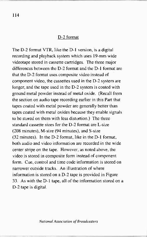
114
D-2 format
The D-2 format VTR, like the D-1 version, is a digital recording and playback system which uses 19 -mm wide
videotape stored in cassette cartridges. The three major differences between the D-2 format and the D-1 format are
that the D-2 format uses composite video instead of component video, the cassettes used in the D-2 system are
longer, and the tape used in the D-2 system is coated with
ground metal powder instead of metal oxide. (Recall from the section on audio tape recording earlier in this Part that tapes coated with metal powder are generally better than
tapes coated with metal oxides because they enable signals to be stored on them with less distortion.) The three
standard cassette sizes for the D-2 format are L -size
(208 minutes), M -size (94 minutes), and S -size
(32 minutes). In the D-2 format, like in the D-1 format,
both audio and video information are recorded in the wide
center stripe on the tape. However, as noted above, the
video is stored in composite form instead of component
form. Cue, control and time code information is stored on
narrower outside tracks. An illustration of where
information is stored on a D-2 tape is provided in Figure 33. As with the D-1 tape, all of the information stored on a
D-2 tape is digital.
National Association of Broadcasters

115
D-3 format
The D-3 format is essentially the same as the D-2 format
except that it uses' -inch tape instead of 19 mm tape.
One-half inch is equal to 12.7 mm, so the' -inch tape is
narrower than the 19 mm tape. The narrower tape and
smaller cassettes of the D-3 format enable the equipment
associated with it to be of a smaller size and lighter weight.
This makes D-3 equipment particularly useful for electronic
news gathering (ENG) and other applications that require
the use of portable VTRs.
M, Betacam, M -II and BetacamSP formats
The M, Betacam, M -II and BetacamSP formats use 1/2 -inch
videotape to record component video information in analog
form. It was the success of these small size VTR formats
that led to the development of the D-3 format.
Digital Betacam, DVC Pro formats
These are the digital successors to the small size VTR
formats like Betacam.
A Broadcast Engineering Tutorial for Non -Engineers

116
Character Generators
A character generator is basically a simple computer
system whose capabilities are limited to having characters
typed on its screen from a keyboard, fed to its screen
through a communications port, or read to its screen from a
disk drive. The user can select both the background color
of the character generator's screen and the color of the
characters that are displayed on the screen. In additional to
allowing alphanumeric characters to be displayed, character
generators also allow other digital images to be displayed - such as logos.
An example of how keyboard input to a character generator
might be used would be when a news reporter's name is
added to the bottom of the screen during a newscast. An
example of how an external source might supply data to a
character generator through the data port would be when a
warning about a weather emergency is received by a
television station's Emergency Alert System equipment,
and the warning is automatically fed out over the air by
using the character generator to scroll a text message across
the screen.
A typical personal computer may be used as a
character/image generator if it is equipped to output NTSC
National Association of Broadcasters

117
video signals. The video output on the vast majority of
home computer systems does not conform to the NTSC
standard, but add-on boards are available for adding this
capability.
Television Cameras
The television camera, as one would expect, performs
essentially the opposite function of a television receiver.
Whereas the receiver takes an incoming video signal and
uses it to "paint" a series of rapid-fire still photographs
(30 frames per second, 2 interlaced fields per frame) on the
phosphor coating that covers the inside of the TV screen,
the camera takes an incoming video image, coverts it to a
corresponding electric image which has - instead of
variations in light level - variations in electric
charge -density level, and then scans this electric charge
image to produce an electronic version of the video image.
The device that did the scanning of the image in older
television cameras was called a camera tube, or a pickup
tube. In these tubes, an electron beam actually scanned the
electric charge on the inside surface of the tube to create the
electronic version of the video image. In modern cameras,
the device that does the scanning is called a charge coupled
device, or CCD.
A Broadcast Engineering Tutorial for Non -Engineers

118
The CCD used in a television camera is a pair of electronic
matrices. Both of these matrices have a very large number
of individual charge "cells" on them. Each of the cells in
the first matrix is charged up to a level that is proportional
to the amount of light that is hitting it through the lens of
the camera. All of the individual charges from each one of
the cells in the first matrix are transferred to corresponding
cells in a second matrix which is shielded from light. The
circuitry in the camera then scans the second matrix to
produce an electronic version of the video image.
lens 151 matrix cells have electric charges that mimic
image from lens
2nd matrix copies cells from
151 matrix 30 times per second
video 0 scanner 0 signal
Figure 34: The CCD Imaging Process
The reason that the charges in the first matrix must be
transferred to a second matrix before they are scanned by
the camera circuitry is that the charges in the first matrix
are constantly changing as the image through the lens
National Association of Broadcasters
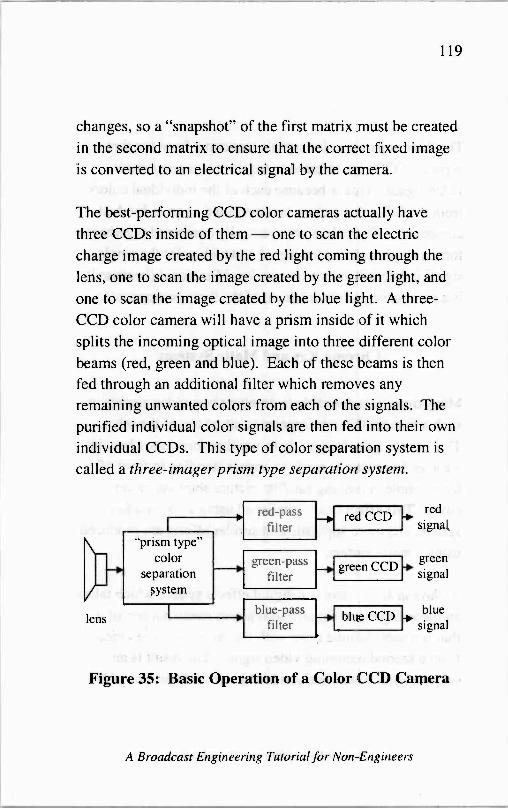
119
changes, so a "snapshot" of the first matrix must be created in the second matrix to ensure that the correct fixed image is converted to an electrical signal by the camera.
The best -performing CCD color cameras actually have
three CCDs inside of them - one to scan the electric charge image created by the red light coming through the
lens, one to scan the image created by the green light, and
one to scan the image created by the blue light. A three-
CCD color camera will have a prism inside of it which
splits the incoming optical image into three different color
beams (red, green and blue). Each of these beams is then
fed through an additional filter which removes any
remaining unwanted colors from each of the signals. The
purified individual color signals are then fed into their own
individual CCDs. This type of color separation system is
called a three -imager prism type separation system.
r "prism type"
color separation
system
red -pass filter
green -pass filter
lens ' blue -pass
filter
red CCD red
signal
--
green CCD green signal
blue CCD L blue
signal
Figure 35: Basic Operation of a Color CCD Camera
A Broadcast Engineering Tutorial for Non -Engineers

120
The three separate color signals that come from the three
separate CCDs are referred to together as a component
video signal. This is because each of the individual colors
from the full -color picture is transmitted as an individual
component. The colors are eventually combined together to
form a single color video signal at which point the single
signal is referred to as a composite video signal (because it
is a composite picture made up of the three components.)
Chroma Key and Matte Systems
Many times it is desirable to combine two video signals in
such a manner that one appears to sit on top of the other.
This occurs quite frequently in weather forecasts when the
weather forecaster is made to appear standing in front of,
for example, a moving satellite picture showing cloud
cover. This effect is accomplished using a chroma key
system, and more sophisticated similar effects are produced
using a matte system.
A chroma key system is a digital effects system which takes
an incoming video signal and replaces every portion of it
that is a user -defined color with the corresponding video
from a second incoming video signal. The result is an
output signal which has combined selected portions of the
National Association of Broadcasters

121
two input signals. Let's look at the various specific aspects of a typical weather forecasting set to get an understanding of how a chroma key system works.
On a typical weather forecasting set, the weather forecaster stands in front of a large, blank wall that is painted one
solid color, typically blue or green. It is important that this
background color not match the color of any of the
forecaster's clothing, hair, skin, etc. A camera is focused
on the weather forecaster with the wall in the background, and the video from this camera provides the first input signal for the chroma key system. The second input signal for the chroma key system is simply the satellite video image. The chroma key system is then instructed to take
every portion of the first input signal that matches the color of the wall and replace it with the corresponding portion of the second video signal. Since the wall should be the only
thing in the first video signal that is the same color as the
wall, this replacement creates the illusion in the final
product that the weather forecaster is standing in front of the satellite video. That's why it is important that the
forecaster's clothing, hair, skin, etc., not match the wall, or
those elements would become part of the illusion, as well.
A chroma key system makes the weather forecaster's job a
little bit tricky because the weather forecaster wants to
appear to be pointing to portions of the satellite video in the
A Broadcast Engineering Tutorial for Non -Engineers
122
final product. In order to do this, however, the forecaster
must actually be pointing to places on the blank wall.
Typically, there is a monitor showing the composite picture
of the forecaster and the satellite video somewhere just out
of range of the camera that is focused on the forecaster.
The forecaster looks at this monitor while doing the
forecast to insure that he/she is pointing to the correct
portion of the satellite video.
A matte system operates in essentially the same manner as
a chroma key system -except that the matte system can
replace multiple colors in the first video signal with the
video from the second video signal.
Video Mixing Board
A video mixing board (sometimes referred to simply as a
master control board) performs essentially the same
function as the audio mixing board that was discussed
earlier in the radio section. The main difference between
the two, of course, is that the video mixing board is mixing
audio and video signals instead of just audio signals.
Another important difference between audio mixing and
video mixing, which we have already covered, is the fact
that the timing of the video signals being mixed is much
more important than the timing of audio signals being
National Association of Broadcasters
123
mixed because switching between two video signals whose vertical synch pulses are not precisely synchronized will
usually result in a "bounce" in the output video signal.
A good way to think about the mixing and switching of video signals, in comparison with the mixing and switching
of audio signals, is to think of a completely black video signal as very quiet (but not completely silent), and a
completely white video signal as very noisy. The reason for
this is that the darker a video image is, the lower the
voltage of its corresponding NTSC video signal and,
conversely, the lighter the image the higher the voltage of its corresponding video signal. Although the completely black signal has a low voltage, it does not have zero
voltage. The zero voltage portions of an NTSC video signal are reserved to the horizontal and vertical blanking intervals.
Because the low voltage black signal does not have zero
voltage, it cannot be added to another video signal without
having any effect on the other signal. If a completely black
screen and a "normal" video image are combined together,
the result is a somewhat dimmer looking version of the
"normal" video. Conversely, if a completely white screen
and a "normal" video image are combined together, the
result is a brighter version of the "normal" video.
A Broadcast Engineering Tutorial for Non -Engineers

124
Modern video mixing boards allow many different effects
to be used while switching between input signals. These
include wipes, fades and blinds, among others. They also
allow the board operator to create a "picture -in -picture"
effect by inserting one or more video images inside another.
Just as is the case in a radio studio, after a television signal
leaves the master control board there are several important
pieces of equipment that it travels through before being
delivered to the transmitter. This equipment can be broken
down into three categories: distribution amplifiers and
routing switchers, audio processing equipment and
Emergency Alert System (EAS) equipment. We are not
going to discuss audio processing equipment here since it
was covered earlier in the section on radio studios. The
video portion of a television signal is not processed
(compressed or expanded) to any significant degree
because, in an NTSC video signal, the dynamic range
(difference between the highest level of signal and the
lowest level of signal) is a very important aspect of the
signal.
Distribution Amplifiers and Routing Switchers
Usually, the output of the master control board (the
station's on -air program) will be fed into a distribution
National Association of Broadcasters

125
amplifier which, in turn, feeds several "copies" of this signal to other parts of the studio. (Recall that a
distribution amplifier allows a single input signal to feed multiple sources with "copies" of the signal that are equal
in quality to the original.) These "other parts of the studio" might include recording equipment, or simple monitors for
viewing the outgoing program, and they will usually include at least one routing switcher.
inputs
outputs
Each output of the routing switcher can be connected to any one of the inputs at any given time
Figure 36: A Typical Routing Switcher Configuration
A routing switcher is a device that has multiple inputs and
multiple outputs, and a user of any particular output
channel can select to have it connected to any particular input channel at any time. The great advantage of a routing switcher is that it allows a number of different signals to be
A Broadcast Engineering Tutorial for Non -Engineers
126
fed to a particular place - such as an input channel on a
video mixing board - through only one connection. In
other words, instead of wiring all of the signals going into
the routing switcher directly into the mixing board (which
would take up numerous input channels on the mixing
board) each of the inputs is routed through the switcher and
few output channels from the switcher are connected to the
mixing board, giving the board operator access to all of the
switcher input channels without taking up more mixing
board inputs than necessary.
As is the case with audio systems, there are now video
servers available for storing and distributing digital video
signals. A video server is, basically, a powerful computer
that is capable of receiving digital video signals from video
sources and distributing them to multiple locations. The
major difference between a video server and a distribution
amplifier is that a video server is capable of storing digital
video information on its disk drives for later retrieval while
the distribution amplifier is not equipped to store any video.
Emergency Alert System Equipment
As noted in the earlier section on radio studio equipment,
Emergency Alert System (EAS) equipment must be
installed somewhere in a broadcast station's air chain. This
National Association of Broadcasters

127
equipment will typically be installed between the output of
the master control board and the transmitter. The only
significant difference between the EAS equipment used in a
TV studio in comparison to the EAS equipment used in a
radio studio is that the equipment used in the TV studio
must have the ability to interrupt both audio and video, or
at least to interrupt audio and insert a video text message
over top of a portion of the normal video.
monitoring assignment #1
audio source from studio
monitoring assignment #2
Y EAS decoder
video source from studio
EAS encoder
video text insertion
equipment
1
audio in
r
p video
in
transmitter
Figure 37: EAS Equipment in a TV Station Air Chain
A Broadcast Engineering Tutorial for Non -Engineers

128
National Association of Broadcasters

129
Part II: The Studio - Transmitter Link
A Broadcast Engineering Tutorial for Non -Engineers

130
The studio -transmitter link, or STL, is the means by which
the program material produced in the studio is transported
to the transmitter for broadcast. If the station's transmitter is located adjacent to its studios, then the STL might simply
be a cable, or set of cables, stretching from the studios to
the transmitter. More often, however, the transmitter is
located at a remote location, such as the top of a mountain
or tall building. When the transmitter is located at a great
distance from the studio, there must be some means of
transporting the program material over the property in
between. Though nearly any means of transmitting an
electronic signal can be used as an STL, most broadcasters
use one of two primary methods.
The first of these methods is a microwave link. Microwave
STLs involve the installation of a microwave transmitter
and an associated antenna at the station's studios, and a
microwave receiver and associated antenna at the
transmitter site. The antennas used for most microwave
STLs are called parabolic reflector antennas. They are
shaped somewhat like a typical dish antenna but are
generally rectangular in shape.
There are several important issues that stations using
microwave STLs need to consider. One is that the
transmitting antenna at the station's studios needs to have a
good "view" of the receiving antenna at the transmitter site.
National Association of Broadcasters

131
This means that there cannot be any major obstructions such as mountains, tall buildings, or even heavy foliage,
between the two antennas which would block, or partially
block, the signal being sent to the transmitter site.
If there are obstructions between the studio site and the
transmitter site which will block the microwave STL signal
to any significant degree, then the broadcaster generally has
three options to consider. The first is to relocate the studio
end of the STL, the transmitter end, or both. This can be
done by actually moving the studio and/or transmitter site,
or by simply moving the STL antennas and making additional arrangements to get the STL signal from the
studios to the microwave transmitting antenna and/or from
the microwave receive antenna to the transmitter. The
second option is to raise the height of the microwave
transmitting antenna and/or the microwave receive antenna
to that they can each "see" each other over whatever obstructions are in between them. In some cases, it is
simply not possible, or financially practical, to do either of
these things and the only option left for the broadcaster is to
find a means other than the use of microwave signals to get
the program material from the studios to the transmitter.
The most common means of getting program material to
the transmitter without using microwave transmitting equipment is to use leased telephone lines. The telephone
A Broadcast Engineering Tutorial for Non -Engineers
132
company is capable of providing broadcast quality links
between studios and transmitters. Broadcasters who use
such links feed their signals into a telephone company -provided box or boxes at the studio facility, and
they retrieve them from a telephone company terminal at
the transmitter facility. The main advantage of a leased
telephone line is that it enables the broadcaster to get
program material from the studio to the transmitter without having a line -of -sight path. In most other respects, a leased
line is less desirable than a microwave link.
One of the disadvantages of the leased line is cost. Cost
varies depending on how much capacity is being leased,
and how far it is from the studio to the transmitter, but a
typical stereo connection between a radio studio and a radio
transmitter can run about $200 per month. A microwave
STL system will cost about $10,000 which is about four
years' worth of leased line payments. So, from a long-term
perspective, the microwave link is financially more
attractive than a leased line. (Note that the scales can be
tipped back in favor of the leased line, however, if the
broadcaster must lease additional tower space on which to
install the microwave STL antennas.)
Another disadvantage of the leased line is control in
emergency situations. If, for some reason such as a natural
disaster or a construction accident, the connection between
National Association of Broadcasters
133
the studio and the transmitter is broken, the broadcaster
using the leased line is at the mercy of the telephone
company repair crew. On the other hand, broadcasters with
microwave STLs have control over their own destinies
when disasters strike because it is up to these broadcasters
to maintain their own equipment.
Regardless of what path the signal takes to get to the
transmitter (simple cable, microwave link, or leased phone
line) there is one other quality of the STL that must be
considered whether it is analog or digital.
If the program material produced at the studio is analog,
and the transmitter accepts an analog input, then an analog
STL can be used without the need for any additional
equipment. If, on the other hand, the program material
produced at the studio is analog, and a digital STL is
employed, then an additional piece of equipment called an
analog -to-digital converter, or A/D converter, is required at
the studio end of the STL. The same is true at the
transmitter end- if the transmitter only accepts analog
inputs, and a digital STL is employed, then a
digital -to -analog converter (D/A converter) is needed at the
transmitter site.
The trend in broadcasting, as in most telecommunications -
related fields, is toward digital equipment. Broadcast
A Broadcast Engineering Tutorial for Non -Engineers
134
studios that have been converted to digital can connect to a
digital STL without the need for an A/D converter.
However, if the data rate of the digital signals used in the
studio is faster than the data rate of the digital STL, then a
device to perform some form of data compression will be
needed at the studio end of the STL. This compression
device takes the incoming digital data stream from the
studios and encodes it in a more efficient manner, thus
enabling the data stream that it sends out to be at a lower
rate than the incoming signal. Some forms of data
compression are lossless, meaning that the original,
uncompressed data stream can be reconstructed in its
entirety from the compressed data. Other forms of
compression are lossy, meaning that some of the data in the
original material is lost for good in the compression process. The advantage of lossy compression is that it is
generally more efficient (i.e., it permits the compressed data
stream to be sent to the transmitter at a lower rate, and
therefore at less expense). The disadvantage, of course, is
that some of the original data is lost for good. There are
forms of lossy compression, however, for which the loss of
data is not detectable to the human ear (and eye, in the case
of television) - so it is a very attractive option for many
broadcasters.
National Association of Broadcasters
135
Part III: The Transmitter Site
A Broadcast Engineering Tutorial for Non -Engineers

136
From an engineering standpoint, the transmitter sites for all
types of broadcast facilities (AM, FM and TV) are
generally very similar. As shown in Figure 38, each
transmitter site must have a transmitter to create the
high-powered signal for broadcast, a transmission line to
carry the signal from the transmitter to the antenna, and an
antenna. Although AM, FM and TV transmission facilities
are generally very similar, there are some significant
differences between them - most notably the different
types of antennas that are used. We will cover antennas
later, after we talk about the transmitter and the
transmission line-but first let's talk about the arrival of
the signal to be transmitted at the transmission site.
antenna
transmission line \
transmitter
4- tower
Figure 38: Basic Components of Transmitter Site
National Association of Broadcasters
137
A signal arrives at the transmitter site via the
studio -transmitter link, or STL, (see Part II for a discussion
of the STL). The STL can be analog or digital. If it is
digital, and the transmitter inputs are analog, then the signal
must be converted to analog using a digital -to -analog (D/A)
converter.
Once the signal has arrived at the transmitter site and gone
through any necessary converters, it is then in one of two
forms -a component signal, or a composite signal. A
component audio signal simply consists of the same audio
signals that travel around the studio. These signals are
essentially the same (except for a slight difference in signal
level) as those that come out of the "line out" terminals on
home electronics equipment. A component video signal
consists of three separate signals - usually one for red
picture information, one for green, and one for blue; or, one
for monochrome picture information and two used to add
color to the monochrome signal. Component video signals
are used in a number of studio applications, but it is
unusual for a component video signal to be fed from the
studio to the transmitter site because of the additional cost
and complexity involved. Usually the video information
sent to the transmitter site is composite. The NTSC video
standard discussed in Part I is a composite signal (because
it includes all of the video information in a single signal),
and it is in the NTSC composite format that video
A Broadcast Engineering Tutorial for Non -Engineers

138
information is usually sent to an analog television
transmitter site from the studio. The ATSC video standard
discussed in Part I is also a composite signal, and a digital
television signal can be delivered to the transmitter from
the studio in this format.
If a component signal arrives at the transmitter site over the
STL (as is often the case with audio) then it must first be
converted to a composite signal before it can be fed to the
transmitter.
So, you ask, what is a composite signal ... and why is it
needed? Well, a composite signal is, basically, a single
signal which contains all of the information from multiple
component signals. A simple example of a composite
signal is a monophonic audio signal. Most recorded music
nowadays has been recorded in stereo. If a radio station is
broadcasting in mono, and it is playing a stereo recording, it
will want its monophonic signal to include both the left and
right channels from the recording. Consequently, it needs
to take its component signals (the left and right channel
audio) and add them together to make a single signal that
contains both the right and left channel information -a composite signal.
A monophonic radio signal is a simple example of a
composite signal. Even radio stations that broadcast stereo
National Association of Broadcasters

139
music need to create a composite signal. The reason is
simple - even though these stations are broadcasting both
left and right channel audio information, they only have one
channel over which to transmit it (their carrier frequency,
e.g., 92.7 MHz). So, they need to somehow combine the
two audio signals they have into a single signal in such a
manner that will permit this single signal to be separated
and heard as two distinct left and right channels by a stereo
receiver - but at the same time will allow monophonic
receivers to hear a single, composite signal that contains
both left and right channel information.
Stereo sound is very prevalent at FM radio and TV
broadcast stations, and it is used to a somewhat lesser
degree in AM radio stations. No matter what type of
broadcast station is involved (AM, FM or TV), all stereo
broadcast systems use the same method of coding and
decoding the left and right audio channel in order to insure
that both stereophonic and monophonic receivers are able
to play their audio.
Because monophonic receivers must still be able to receive
a signal from a stereophonic transmitter, it is not sufficient
to simply transmit a left channel signal and a right channel
signal. Instead, a main program channel must be
transmitted that can be used by a monophonic receiver (i.e.,
the main program signal must consist of both the left and
A Broadcast Engineering Tutorial for Non -Engineers

140
right audio channel) and a stereo program channel must be
transmitted that can be coupled with the main program
channel to produce left and right program material at a
stereo receiver. Figure 39 illustrates the method that broadcasters use to achieve this objective.
Note how, in Figure 39, a "main" signal can be transmitted which consists of both the left and right audio channels. Then, in addition, a supplementary signal is transmitted which, when added to and subtracted from the main signal,
can be used to produce stereo sound at the receiver.
right
A monophonic receive
left right
receiver only this signal.
will
2 x left left - Ieft
ADD rie
p
ADD
left
I
SUBTRACT hUBTRACp 2 x rieht right + r
transmitter L
stereo receiver
Figure 39: Block Diagram of Stereo Transmission System
Before we lose track of where we are, let's review. Thus far in this Part we have learned that the information to be
transmitted by the transmitter arrives at the transmitter site
National Association of Broadcasters

141
via the studio -to -transmitter link (STL). We have also
learned that, if the signal(s) which arrive at the transmitter
site are not in composite form, then they must be converted
to composite form before being fed to the transmitter. We
know that conversion to composite form is necessary
because each broadcaster has only one channel over which
to transmit programming.
The Stereo Generator
Whether we are talking about an FM or TV station, the
stereo generator is the piece of equipment that is used to
create the composite stereo signal. A stereo generator will
generally have two inputs - one for left channel audio and
one for right channel audio, and it will have a composite
output which is a one -wire connection that carries the
composite signal. The composite output of the stereo
generator is the left + right signal, the stereo pilot (19 kHz
for FM, 15.734 kHz for TV) and the left - right signal
centered on a frequency that is two times the stereo pilot
frequency.
A Broadcast Engineering Tutorial for Non -Engineers

142
modulation level main
program material
Ç stereo pilot
stereo program material
4.
0 15 l9 t t 38 53 +100 kHz
FM baseband
Figure 40: Composite Output of FM Stereo Generator
AM stations do not use stereo generators, per se. The actual combining into a "single wire signal" of the left + right and left - right signals in an AM stereo system is
done by the exciter. The composite output of the AM stereo exciter is the left + right signal and the left - right signal, the latter of which is slightly shifted in time (delayed behind) the left + right signal to insure that it does not interfere with monophonic AM receivers. (Stereo AM receivers know to look for the time -shifted left - right signal.) The term used to describe this time -shifted signal is quadrature amplitude modulation. It will be discussed in
a little more depth in the section on subcarrier generators.
If composite audio is fed over the STL, then the stereo generator will be located at the studio site. If component
National Association of Broadcasters
143
audio is fed over the STL, then the stereo generator will be
located at the transmitter site.
Typically, the output of the stereo generator is fed into the
exciter (see the section on the exciter below). For stations
that do a lot of audio processing, however, there is
sometimes some additional audio processing equipment
installed between the stereo generator and the exciter,
usually to aid in efforts to make the station's audio sound
louder.
Subcarrier Generators
Subcarrier generators are devices used to add additional
information to a broadcast signal which may or may not be
associated with the broadcaster's main programming. For
example, it is very common for FM radio stations to
transmit paging information via subcarrier. Although less
common, it is also possible for an analog television station
to use a subcarrier to transmit a second audio signal, in
addition to the audio that accompanies its video signal.
Digital television stations can also transmit additional
audio, video, or data signals - however, the way digital
television signals are constructed and transmitted is
completely different from the way analog radio and
television signals are constructed and transmitted,
A Broadcast Engineering Tutorial for Non -Engineers

144
Technically speaking, the capacity to send additional audio, video and/or data over a digital television channel is not made available through the use of subcarriers. Instead, the digital television signal, itself, is simply a series of digital bits, some of which can be allocated for supplementary audio, video and/or data. We will talk about the transmission aspect of digital television a bit later.
The stereo generator (see earlier section) is a subcarrier generator which generates the stereo pilot signal and the stereo subcarrier.
A subcarrier is a special type of carrier. It has all of the characteristics of a carrier, except that it, itself, must be added to the "host" carrier in order to be delivered to a
receiver. Subcarriers can exist in AM, FM and TV transmission systems. However, AM radio channels have very little extra room for subcarriers after the audio is
added so subcarriers are used very little - if at all - in
AM radio systems. On the other hand, subcarriers are very common in FM radio and TV because there is plenty of extra room for them to be added. Although the limitations of the AM channel generally prevent AM broadcasters from using subcarriers, these broadcasters can still transmit "subcarrier-like" signals using quadrature amplitude modulation (QAM), which will be explained shortly.
National Association of Broadcasters
145
One of the most common subcarriers in use today is the
stereo pilot. The stereo pilot is an unmodulated subcarrier - that is, a subcarrier that does not have any additional
information added to it. The main purpose of the stereo
pilot is to tell receivers that the host FM or analog TV
station is broadcasting in stereo. If an FM or analog TV
station does not transmit the standard stereo pilot signal,
then the receivers that receive its signal will assume that the
station is broadcasting a monaural program - and they will
not split the received audio into a left and right channel.
Figure 41 shows the 19 kHz stereo pilot in the baseband
spectrum of a standard FM broadcast station. (For the rest
of this discussion about FM/TV subcarriers, we will use the
FM baseband signal for illustrative purposes. The analog
TV aural baseband signal is essentially the same as.the FM
baseband signal, so if you understand how subcarriers are
added to FM signals you also understand how subcarriers
are added to analog TV aural signals.)
A Broadcast Engineering Tutorial for Non -Engineers

146
modulation level
stereo pilot
main program material
0 15 19
FM baseband
1
+100 kHz
Figure 41: FM Monophonic Signal with Stereo Pilot
To understand the figures being used here to illustrate FM subcarriers, it is necessary to understand what the FM baseband, or FM composite baseband is. The FM composite baseband signal is the signal that comes out of the stereo generator (and any subcarrier generators, if they are used). From 0 to about 15 kHz, it contains the same range of audio signals that you will find on a typical equalizer used in a home stereo system. What makes the composite baseband signal special is that there are
additional signals added to the audible ones, signals that are
just above the range of human hearing and which therefore cannot be heard by the human ear. These signals are used to transmit the encoded stereo information, and other additional information, in the manner described below.
National Association of Broadcasters

147
The stereo pilot, in addition to being used to alert receivers
to the fact that a station is transmitting in stereo, has
another very important purpose - its harmonics can be
used as other subcarriers, as needed. Harmonics are a
"side -effect" of radio transmissions. They are extraneous
signals, produced on frequencies that are separated from the
main frequency by multiples of itself. The second
harmonic of 19 kHz is (2 x 19 kHz), or 38 kHz. The third
harmonic of 19 kHz is (3 x 19 kHz), or 57 kHz.
In the FM transmission system, the program material
necessary for monaural transmission is transmitted on (i.e.
modulated onto) the main carrier without the use of a
subcarrier. The stereo pilot is the 19 kHz subcarrier, and
the program material necessary to deliver stereo
programming (the "left minus right" signal) is modulated
onto the second harmonic of the 19 kHz stereo pilot (the 38
kHz subcarrier) as shown in Figure 42.)
A Broadcast Engineering Tutorial for Non -Engineers

148
modulation level
I
stereo pilot
15 19
m
main progra material
o
stereo program material
t t 38 +100 kHz
FM baseband
Figure 42: FM Stereophonic Signal
As Figure 42 indicates, the monaural program material occupies the baseband spectrum from 0 to 15 kHz. The stereo pilot appears at 19 kHz, and the stereo program material occupies the baseband spectrum from 15 kHz
below, to 15 kHz above, the 38 kHz subcarrier, which is the spectrum from 23 kHz to 53 kHz in the FM baseband.
(Note: As shown in Figure 42, the stereo program material occupies the spectrum from 15 kHz below to 15 kHz above its 38 kHz subcarrier. The main program material, on the
other hand, only occupies the spectrum from 0 to 15 kHz in
the FM baseband - it does not extend down to -15 kHz - because, in the baseband, the main program material is not
modulated onto any carrier or subcarrier. It is only when
the program material is modulated onto a carrier or
subcarrier that the "plus and minus" effect occurs. For a
National Association of Broadcasters

149
little more discussion on this "plus and minus" effect, see
the section on the exciter which appears after this one.)
Figure 42 illustrates the fact that an FM stereo signal
actually only occupies a little more than half of the
baseband spectrum allocated to it. The excess channel
capacity that is left over presents a significant opportunity
for FM broadcasters to generate additional income by
leasing out some, or all, of their excess channel capacity to
subcarrier service providers. The same is true for TV
broadcasters, though the subcarrier space available to them
is slightly different than the subcarrier space available to
FM stations.
The three most common FM -band subcarriers in use today
are the 57 kHz, 67 kHz and 92 kHz subcarriers.
Widespread use of the 67 kHz subcarrier began back in the
days when the FCC did not allow subcarriers to occupy any
of the baseband spectrum above 75 kHz. At that time,
centering a subcarrier at 67 kHz allowed it to make
optimum use of available bandwidth and at the same time
remain as far removed from the stereo program material as
possible, as illustrated in Figure 43.
A Broadcast Engineering Tutorial for Non -Engineers

150
modulation level main
progra material
o
stereo pilot
15 19
m stereo program material
67 kHz subcarrier
f t T
38 67 +100 kHz FM baseband
Figure 43: FM Stereophonic Signal with 67 kHz Subcarrier
In the early 1980s, the FCC modified its rules to allow
subcarrier use of the spectrum from 75 kHz to 99 kHz in
the FM baseband. This has resulted in widespread use of the 92 kHz subcarrier, which has become a de facto standard because it allows the subcarrier's operations to
stay below 99 kHz while maintaining a safe separation distance from a 67 kHz subcarrier. Figure 44 shows the
baseband of an FM station transmitting stereo programming
and two subcarriers (one each at 67 kHz and 92 kHz).
National Association of Broadcasters

modulation level main
program material
stereo pilot
stereo program material
67 kHz subcarrier
92 kHz subcarrie
0 15 19
151
t t t 38 67 92 +100 kHz
FM baseband
Figure 44: FM Stereophonic Signal with 67 and 92 kHz Subcarriers
In 1993, the National Radio Systems Committee (NRSC)
adopted a standard for transmitting data at 1187.5 bits per
second on a subcarrier at 57 kHz in the FM baseband. This
standard is called the United States Radio Broadcast Data System (RBDS) Standard. An updated edition of this standard was adopted by the NRSC in 1998.
The recommended bandwidth for the RBDS signal is
approximately 4 kHz (i.e., 57 kHz ± 2 kHz). It is centered
on 57 kHz because 57 kHz is the third harmonic of 19 kHz,
the FM stereo pilot frequency. This aids in both transmitter
and receiver design because it eliminates the need for a
separate radio frequency oscillator for the RBDS signal.
A Broadcast Engineering Tutorial for Non -Engineers
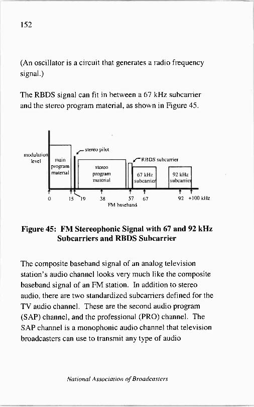
152
(An oscillator is a circuit that generates a radio frequency
signal.)
The RBDS signal can fit in between a 67 kHz subcarrier
and the stereo program material, as shown in Figure 45.
modulation level main
program material
stereo pilot
stereo
program material
d'RBDS subcarrier
67 kHz subcarrier
92 kHz subcarriei
t t 0 15 19 38 57 67
FM baseband
T
92 +100 kHz
Figure 45: FM Stereophonic Signal with 67 and 92 kHz Subcarriers and RBDS Subcarrier
The composite baseband signal of an analog television
station's audio channel looks very much like the composite baseband signal of an FM station. In addition to stereo
audio, there are two standardized subcarriers defined for the
TV audio channel. These are the second audio program
(SAP) channel, and the professional (PRO) channel. The
SAP channel is a monophonic audio channel that television
broadcasters can use to transmit any type of audio
National Association of Broadcasters

153
information they desire. To date, there are not many
broadcasters making use of this channel. The PRO channel
can be used for sending voice or data information. It is a
narrower channel than the SAP channel and therefore only
permits voice transmissions of a quality similar to a typical
telephone line. The PRO channel, like the SAP channel, is
not yet in widespread use. Television broadcasters are not
required to use the SAP or PRO channels if they choose to
transmit subcarriers. They may, instead, transmit
subcarriers on different baseband frequencies if they desire.
An illustration of the typical analog TV station's aural
baseband signal is provided in Figure 46. The frequencies on the horizontal axis have been rounded off to make the
illustration easier to read.
modulation level
stereo pilot
stereo main program
progra material materia
o
m
I
15 17
t
31 46
16 TV aural baseband
SAP
t
79
Figure 46: TV Aural Baseband Signal
A Broadcast Engineering Tutorial for Non -Engineers
PRO
n t
+102 kHz

154
As was noted earlier, the AM broadcast channel is
significantly narrower than the FM broadcast channel and
the TV broadcast channel. For this reason, there is an
extremely limited amount of channel capacity available for
AM subcarriers. To illustrate this point, Figure 47 shows
the AM- and FM -band emissions masks defined by the
FCC. The emissions mask is the limit placed on the signal
strength of the broadcast signal, and it is defined over a
range of frequencies surrounding the carrier frequency. For
AM -band stations, the emissions mask is defined in Section
73.44 of the FCC Rules. For FM -band stations it is defined
in Section 73.317. A broadcast station's signal strength at
specific frequencies must decrease as the frequencies
become farther away from the carrier. This is to protect
stations operating on nearby frequencies from interference.
National Association of Broadcasters

155
-25 dB - r
fcárrier -201 120 kHz -240
-10.2 10.2
* tárrier * -120 -82.5 82.5 120
AM Mask FM Mask
= maximum spectrum available to broadcasters
-25 dB
240 kHz
Figure 47: Comparison of AM- and FM -Band Emissions Masks
As Figure 47 illustrates, the radio spectrum available to an
AM station is approximately ten percent of that available to
an FM station. Furthermore, an AM station's program material (whether the station is broadcasting in monaural or
stereo mode) occupies all of the radio spectrum, and all of the baseband spectrum, assigned to the station. This makes
it extremely difficult to place a subcarrier in an AM channel
without the subcarrier causing interference to AM
reception. Despite this difficulty, however, methods have
been proposed for installing such subcarriers.
In 1992, the National Radio Systems Committee requested
proposals for an AM enhancement to RBDS. In response
to this request, a proposal was received which described a
A Broadcast Engineering Tutorial for Non -Engineers

156
data subcarrier system for the AM band that called for the
use of data subcarriers at 9.2 kHz and 9.8 kHz above the
AM carrier, at a level well below the main program material (see Figure 48). Development of this system has
never been completed, however, because it was later
determined that the data subcarriers were audible on
wide -band AM receivers.
r
proposed AM -band subcarriers (± 9.2 kHz and ± 9.8 kHz from main carrier)
= spectrum used by stereo program signal
Figure 48: Proposed AM-Band Subcarriers
National Association of Broadcasters
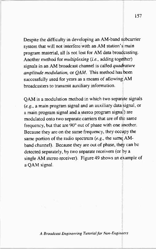
157
Despite the difficulty in developing an AM -band subcarrier
system that will not interfere with an AM station's main
program material, all is not lost for AM data broadcasting.
Another method for multiplexing (i.e., adding together)
signals in an AM broadcast channel is called quadrature amplitude modulation, or QAM. This method has been
successfully used for years as a means of allowing AM
broadcasters to transmit auxiliary information.
QAM is a modulation method in which two separate signals
(e.g., a main program signal and an auxiliary data signal, or
a main program signal and a stereo program signal) are
modulated onto two separate carriers that are of the same
frequency, but that are 90° out of phase with one another.
Because they are on the same frequency, they occupy the
same portion of the radio spectrum (e.g., the same AM -
band channel). Because they are out of phase, they can be
detected separately, by two separate receivers (or by a
single AM stereo receiver). Figure 49 shows an example of
a QAM signal.
A Broadcast Engineering Tutorial for Non -Engineers

158
signal level
I wavelength = 360°
90° (or '4 wave) phase difference
"non" AM signal
QUAM signal
Figure 49: Example of Quadrature Amplitude Modulation (QAM)
It should be noted that the quadrature signal cannot be
much more than 90° out -of -phase from the main program
signal because, if it were, it would begin interfering with
the in -phase signal. That is, if the peaks of the quadrature
signal were to correspond too closely with the valleys of the
in -phase signal, the two signals would end up canceling
each other out.
So, now we know about subcarriers, and the baseband
signal. It is the baseband signal that gets fed into the
exciter for modulation onto the station's main carrier. In
the case of an analog TV station, there are two baseband
National Association of Broadcasters

159
signals (audio and video) fed into two exciters for
modulation onto two carriers. To learn about what the
exciter's function is, keep reading.
The Exciter
The exciter is the device that takes the composite signal and
converts it to a radio frequency signal. In the case of AM
radio, the exciter takes the incoming composite signal and
amplitude modulates it onto the carrier frequency used by
the station in question. In FM radio, the exciter takes the
incoming composite signal and frequency modulates it onto
the station's carrier. In analog television, the video exciter
takes the incoming composite video signal and amplitude
modulates it onto the station's video carrier and the
aural exciter takes the incoming audio signal and frequency
modulates it onto the station's aural carrier. In digital
television, there is a single exciter that takes the digital
ATSC data stream and modulates it onto the station's carrier using amplitude modulation.
Let's look a little more closely at carrier frequencbes, their
relationship to channels, and the different types of
modulation used in broadcasting.
A Broadcast Engineering Tutorial for Non -Engineers

160
Each radio channel contains one carrier, while each analog television channel contains two carriers - one for audio information and one for video information, and each digital television signal contains a single carrier. A carrier is, quite simply, a signal of a particular frequency to which
additional information is added for delivery to a receiver. The "additional information," as we have just learned, is
the composite signal. A carrier is called a "carrier" because it "carries" the program material, in composite form, to the
receiver. It is then up to the receiver to take the composite signal and convert it back to component form for listening and/or viewing. In the AM broadcast band, carriers are
frequencies between 535 and 1705 kHz. In the FM band they are frequencies between 88 and 108 MHz. In the TV
bands they are frequencies between 54 and 72 MHz, 76 and 88 MHz, 174 and 216 MHz and 470 and 806 MHz.
Now that we understand how all broadcast transmitters have to be fed a composite signal for transmission on their single carrier frequency (or, in the case of analog TV
stations, their two carrier frequencies), let's take a few
moments to learn about how the various types of transmission (AM, FM and analog TV and digital TV) are
different. We are going to start with AM and FM
transmission because, once you understand these two,
understanding analog television is easy. Why? Because an
analog television signal is simply composed of one AM and
National Association of Broadcasters

161
one FM signal. The FM signal that is part of an analog TV
signal is the TV station's audio - and there is really very
little technical difference between a TV station's audio
signal and an FM radio station's signal. An analog TV
station's video signal is basically very similar to an AM
radio station's signal - except, of course, that the TV
station is transmitting a series of codes that are used by a
TV receiver to paint a video picture on the screen, while the
AM radio station is transmitting audio information. Once
you understand the basics of AM and FM transmission you
will be able to gain an understanding of analog TV
transmission rather easily. Digital TV transmission is
considerably different than analog TV transmission. We
will discuss digital TV transmission separately, after we
cover analog transmission.
signal +I+l+l signal --~
level level -- -4 4- --
Fca rier Fcarrier + 10.2 kHz
AM (a)
Fcarrier
FM (b)
t F1+75 kHz
Figure 50: Radio Spectrum Occupied by AM and FM Signals
A Broadcast Engineering Tutorial for Non -Engineers

162
AM stands for amplitude modulation. In AM
transmissions, program material is modulated onto the carrier signal in a manner that causes changes in the
amplitude of the carrier signal which correspond to changes
in the volume of the source program material. In AM
transmissions, the frequency of the modulating signal (the
program material) is combined with the carrier to form a
composite signal which, at any particular instant in time,
will have a frequency somewhere between the carrier frequency minus about 10 kHz and the carrier frequency
plus about 10 kHz. (Remember, a composite signal is a
signal that is formed by adding two or more signals
together. In the case of the composite radio frequency
signal, one can think of the two signals being added as the
carrier and the composite baseband signal.) The reason that
the spectrum occupied by the AM signal extends out from
the carrier by about ± 10 kHz is that the modulating signal
(the program material) is within the audio frequency range
from 0 to about 10 kHz. The reason that the spectrum
occupied by the composite carrier signal extends from
about 10 kHz below the carrier to 10 kHz above the carrier - instead of simply from the carrier to about 10 kHz above
the carrier - is that both the program material and the
carrier wave have "upward sloping" and "downward
sloping" components, like the waves on the ocean, and the
composite carrier signal that results from the addition of a
National Association of Broadcasters

163
particular piece of program material will vary (between
carrier plus modulating program frequency and carrier
minus modulating program frequency) depending on
whether the carrier and the modulating program frequency
happen to be sloping upward or sloping downward at the
instant that they are combined.
In an AM transmission, the bandwidth of the composite
radio frequency signal remains essentially constant (carrier
frequency ± about 10 kHz) while the amplitude of the
composite carrier signal increases and decreases with the
level (volume) of the modulating signal.
FM stands for frequency modulation. In FM transmissions,
program material is modulated onto the carrier signal in a
manner that causes changes in the frequency of the carrier
signal which correspond to changes in the volume of the
source program material. In FM transmissions, the
frequency of the modulating signal (the program material)
is combined with the carrier to form a composite radio
frequency signal which, at any particular instant in time,
will have a frequency somewhere between the carrier
frequency minus about 75 kHz and the carrier frequency
plus about 75 kHz. The reason that the spectrum occupied
by the FM signal extends out from the carrier by about
±75 kHz is that the Federal Communications Commission
has stipulated that this is as much frequency deviation as it
A Broadcast Engineering Tutorial for Non -Engineers

164
will allow in the FM band in order to protect signals on
adjacent channels from interference. As with the AM
signal, the reason that the spectrum occupied by the
composite radio frequency signal extends from about 75 kHz below the carrier to about 75 kHz above the carrier - instead of simply from the carrier to about 75 kHz above
the carrier - is that both the modulating signal and the
carrier wave have upward sloping and downward sloping components, and the composite carrier signal varies
(between carrier plus modulating program frequency and
carrier minus modulating program frequency) depending on
whether the carrier happens to be sloping upward or sloping
downward at the instant that the program material is added.
In an FM transmission, the amplitude of the composite radio frequency signal remains essentially constant while
the bandwidth of the composite carrier signal increases and
decreases with the level (volume) of the modulating signal.
An illustrative way to picture what happens in an FM
transmission is to imagine a simple tone, say a 1 kHz tone,
as the program material being used to FM modulate a
carrier. Let's imagine that the volume of this tone is
relatively low, so it is not FM modulating the carrier to the
maximum allowed ±75 kHz, but instead it is modulating
the carrier to ±50 kHz. A good way to picture what is
happening in this situation is to imagine a very narrow
National Association of Broadcasters

165
"spike" of a signal which is bouncing back and forth from
50 kHz above the carrier to 50 kHz below the carrier at a
rate of 1000 times per second (1 kHz). Now, if you
imagine that the volume of the 1 kHz tone is increased to
the maximum level allowed by the FCC, then the "spike" would be bouncing back and forth from 7.5 kHz above the
carrier to 75 kHz below the carrier at the same rate - 1000
times per second.
Of course, normal program material consists of many
different frequencies, not just a simple tone. However, the
principle is still the same-each of the individual
frequency components of the program material causes the
composite radio frequency signal to "swing back and forth"
at a rate equal to whatever the frequency of the program
material is, and the distance that the composite radio
frequency signal swings away from the carrier is
determined by the amplitude (volume) of the program
material.
As we noted earlier, analog (NTSC) television signals use a
combination of AM and FM modulation. The video signal
in an analog TV transmission is an AM signal, and the
audio signal is FM. The two major differences between the
AM picture signal in an analog TV channel and an AM
radio signal are 1) the AM picture carrier is carrying video
information instead of audio; and 2) the modulated AM
A Broadcast Engineering Tutorial for Non -Engineers

166
picture signal occupies roughly 25 times as much of the
radio frequency spectrum as a modulated AM radio signal. The FM audio signal in a TV channel is very similar to an
FM radio signal - there are only minor differences between the two.
The video signal in an analog TV transmission would
actually occupy a lot more than about 25 times the spectrum of an AM radio signal if it were not for the fact
that the TV signal uses a special form of AM modulation known as vestigial sideband. Basically, all this means is
that most of the lower half of the TV video signal is not
transmitted (recall that the normal double sideband signal would extend from the video carrier minus the modulating frequency to the video carrier plus the modulating frequency), because the information necessary to recreate the video picture on a receiver can still be obtained even
with this information missing. The main reason this
technique is used is to conserve spectrum. A television channel, as it is, takes up 6 MHz of spectrum - roughly
300 times as much spectrum as an AM radio channel, and 30 times as much as an FM radio channel.
As noted earlier, an analog television station will have two
exciters - one for video and one for audio. In their most common configuration, these two exciters will feed their
output signals into two separate power amplifiers. Then,
National Association of Broadcasters

167
the outputs from the two power amplifiers will be
combined and fed up a single transmission line to a single
antenna.
A digital television station will have a single exciter that
modulates the DTV digital bit stream (which includes all
audio, video and ancillary data being broadcast) onto the
station's carrier frequency. The output of a DTV exciter is
a series of pulses that can each have one of eight different amplitude levels (-7, -5, -3, -1, 1, 3, 5 and 7). The DTV
exciter will output 10.76 million of these pulses every
second. The fact that each pulse can have one of eight distinct amplitude levels enables each pulse to represent three bits of digital data. How is this possible? Table 2
illustrates how it is possible.
A Broadcast Engineering Tutorial for Non -Engineers
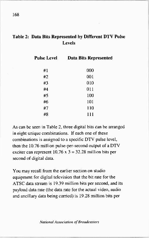
168
Table 2: Data Bits Represented by Different DTV Pulse Levels
Pulse Level Data Bits Represented
#1 000
#2 001
#3 010 #4 011
#5 100
#6 101
#7 110
#8 111
As can be seen in Table 2, three digital bits can be arranged
in eight unique combinations. If each one of these
combinations is assigned to a specific DTV pulse level,
then the 10.76 million pulse -per -second output of a DTV
exciter can represent 10.76 x 3 = 32.28 million bits per
second of digital data.
You may recall from the earlier section on studio
equipment for digital television that the bit rate for the
ATSC data stream is 19.39 million bits per second, and its
payload data rate (the data rate for the actual video, audio
and ancillary data being carried) is 19.28 million bits per
National Association of Broadcasters

169
second. The obvious question is, why is the data rate
coming out of a DTV exciter so much higher than the data
rate of the actual video, audio and ancillary information
being broadcast?
The reason that the DTV transmitter equipment adds so
much additional data to the broadcast signal is that this
additional data is needed to correct errors that occur in the
transmission path. For example, a common problem with
over -the -air analog television signals is "ghosting," a
phenomenon caused when multiple signals from the same
transmitter arrive at the receiver at slightly different times.
This can happen, for example, when a receiver is receiving
a signal directly from the television transmitter and a
second signal that is leaving the same transmitter, bouncing
off of a mountain or ridge, and then reflecting toward the
receiver. Multiple DTV signals arriving at a receiver in this
manner can interfere with one another and cause reception
to be lost. In order to prevent this from happening error
correction codes are added to the broadcast DTV signal
which help receivers to fix problems caused by
interference.
A Broadcast Engineering Tutorial for Non -Engineers

170
The Power Amplifier
A broadcast transmitter has two basic components: an
exciter and a power amplifier. As we just discussed, the
exciter is the piece of equipment that takes the audio, video and subcarrier frequency signals received from the studios and encodes them onto a radio frequency signal for transmission through the air. Sometimes the exciter is
installed inside the transmitter housing and other times it is
installed in an equipment rack next to the transmitter. An
exciter, by itself, is actually a low power transmitter. It can
be used to broadcast a signal simply by attaching an
antenna to it. Exciters are not nearly powerful enough, however, to enable a broadcast station to reach its entire coverage area. So, instead of being fed directly into an
antenna, the output of the exciter is fed into a power amplifier which greatly increases the power of the radio frequency signal to be transmitted.
The power amplifier, as one would imagine, is the device at
the transmitter site which uses the most electricity. It must use a lot of electricity in order to create a very strong signal. The heart of many power amplifiers is an electron tube - or, in some cases, two or more tubes. In these amplifiers it is the tube that actually does the amplifying. The tube gets
very hot during transmitter operation and must be cooled by
National Association of Broadcasters

171
a cooling system. Because of the harsh conditions under
which they operate, electron tubes wear out. The speed
with which they wear out varies from tube to tube and
transmitter to transmitter, but they typically have to be
replaced every few years. In order to get away from the
tube -replacement routine, some modem transmitters have
been designed without tubes using solid-state electronics.
Although solid-state transmitters do not require periodic
tube replacement, the electronic components used in their
amplification circuits will still wear out and require
replacement - but typically not for at least a decade or so.
Solid-state electronics have been used very little in the
highest -powered power amplifiers, such as those found in
many UHF TV transmitters, because they are considerably
less efficient than tube amplifiers at these higher powers
and therefore cost the broadcaster too much extra money in
electric bills.
Radio transmitters generally have one signal coming out of
the power amplifier which gets fed to the transmission line.
Analog television transmitters generally have two signals - one coming out of each power amplifier (audio and
video), while digital television signals have only signal
coming out of a single power amplifier. In a typical analog
television system, the audio and video signals are combined
at the output of the power amplifier to form a composite
signal which is then fed into a single transmission line. In a
A Broadcast Engineering Tutorial for Non -Engineers

172
typical digital television system no combining is necessary
because there is only a single signal coming out of the
power amplifier. In some cases, where a television
station's analog and digital frequency assignments are on
adjacent channels, combining of the analog and digital
signals is done after the power amplifiers so that the analog
and digital signals can share the same antenna. If the
analog and digital signals are far apart in frequency,
however, sharing of the same antenna is not a plausible
alternative. This is because antennas are designed to
operate most efficiently on specific frequencies, and an
antenna that is an efficient radiator on one frequency will
generally not be an efficient radiator on most other
frequencies.
The Transmission Line
The transmission line that connects the transmitter to the
antenna is generally either a flexible length of coaxial
cable, a rigid piece of coaxial cable, or a waveguide.
The type of coaxial cable that would be used at a broadcast
transmitter site can be thought of as an extremely thick
piece of cable television wire. This cable is usually thicker
than a typical garden hose. It has to be thick in order to
National Association of Broadcasters
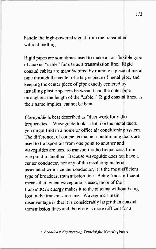
173
handle the high-powered signal from the transmitter
without melting.
Rigid pipes are sometimes used to make a non -flexible type
of coaxial "cable" for use as a transmission line. Rigid
coaxial cables are manufactured by running a piece of metal
pipe through the center of a larger piece of metal pipe, and
keeping the center piece of pipe exactly centered by
installing plastic spacers between it and the outer pipe
throughout the length of the "cable." Rigid coaxial lines, as
their name implies, cannot be bent.
Wave guide is best described as "duct work for radio
frequencies." Waveguide looks a lot like the metal ducts
you might find in a home or office air conditioning system.
The difference, of course, is that air conditioning ducts are
used to transport air from one point to another and
waveguides are used to transport radio frequencies from
one point to another. Because waveguide does not have a
center conductor, nor any of the insulating material
associated with a center conductor, it is the most efficient
type of broadcast transmission line. Being "most efficient"
means that, when waveguide is used, more of the
transmitter's energy makes it to the antenna without being
lost in the transmission line. Waveguide's main
disadvantage is that it is considerably larger than coaxial
transmission lines and therefore is more difficult for a
A Broadcast Engineering Tutorial for Non -Engineers

174
broadcast tower structure to support - particularly when the wind is blowing. It is most often used in situations where the transmitter power is very high because its superior efficiency helps the broadcaster save a significant amount of money on the monthly electric bill.
The Antenna
At the beginning of Part III we noted that all broadcast transmitter sites (AM, FM and TV) are generally very similar - they each have a transmitter, a transmission line, and an antenna. While this is certainly true, it is also true that the broadcast antenna is one thing that differs greatly from one broadcast service to the next.
To understand why antennas vary widely from one service to the next, you must first understand two very basic things. The first is that, in order to operate most efficiently, the length of any antenna (transmitting antenna or receive antenna) must be a function of the wavelength of the transmitted signal. Generally, this means that the antenna will be somewhere between 1/2 -wavelength and '4 -wavelength long.
A wavelength is simply the distance in space that one cycle,
or one "wave," of a signal occupies. (Recall our earlier
National Association of Broadcasters

175
discussion about how a radio/TV signal resembles the
waves on the ocean.) It is easy to calculate the wavelength
of a signal if you know its frequency. The only other bit of
information you need to know is the speed of light, which is
the speed at which all radio and television signals travel.
The speed of light is 300 million meters per second. Let's
calculate the wavelength of some typical broadcast signals:
AM - 1120 kHz
300 million meters/sec _ 1120 thousand cycles/sec = 268 meters/cycle
FM - 98.1 MHz
300 million meters/sec = 98.1 million cycles/sec = 3 meters/cycle
VHF TV - Channel 8 (picture carrier)
300 million meters/sec = 181.25 cycles/sec = 1.7 meters/cycle
UHF TV - Channel 40 (picture carrier)
300 million meters/sec = 627.25 million cycles/sec =' meter/cycle
As the above exercise illustrates, the wavelength of an AM
radio signal is much longer than the wavelength of an FM
radio signal, and the wavelength of an FM radio signal is
significantly longer than the wavelength of a UHF TV
signal. Because of these differing wavelengths, there are
significant differences between the antennas used to
transmit and receive AM, FM and TV signals.
A Broadcast Engineering Tutorial for Non -Engineers
176
Usually, an AM radio station's transmitting antenna is
simply the station's tower. The actual metal structure of
the tower is hot (i.e. energized with electrical energy from
the transmitter) and it can severely shock, and even kill, a
person who walks up to it and touches it while standing on
the ground. For this reason, the FCC requires this type of
tower to have a fence around it that will prevent people
from touching the tower. The height of the tower is
dependent on the transmitting frequency of the AM radio
station. The lower the station's frequency is, the taller the
tower.
Sometimes, multiple AM radio towers are used together as
part of a directional antenna system. Many people have
seen AM DAs, as they are called, while driving down the
road - though they may not have known what they were
looking at. An AM directional antenna involves two or
more tall radio towers standing in a straight line, or
sometimes standing in a parallelogram ("leaning
rectangle") formation. The purpose of the AM DA is to
direct the transmitted energy toward the city of license, but
to block it from traveling toward other cities where it might
cause interference to other licensed stations. Figure 51 and
Figure 52 provide a general illustration of the difference
between a non -directional AM signal and a directional AM
signal.
National Association of Broadcasters
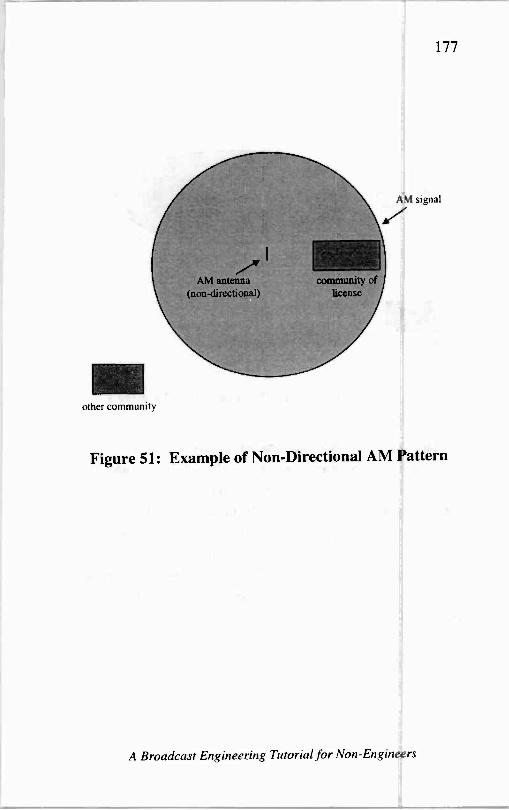
177
AM antenna (non -directional)
other community
community of license
,1I signal
Figure 51: Example of Non -Directional AM Pattern
A Broadcast Engineering Tutorial for Non -Engineers

178
AM signal
AM antenna (directional)
other community
Figure 52: Example of Directional AM Pattern
In many instances, AM stations are authorized by the FCC to operate in a non -directional mode during the day and in a
directional mode at night. The reason for this is that an AM signal that does not interfere with signals in other communities during the day may do so at night due to
skywave propagation. For more information about skywave propagation, and the FCC's methods for ensuring that it does not result in interference to other broadcast stations, see Part V.
National Association of Broadcasters

179
In addition to its directivity, another very important aspect
of an AM antenna is its ground radial system. AM radio
waves travel across the surface of the earth better and
farther when the conductivity of the ground that they are
traveling over is greater. (AM ground conductivity is a
measure of how well the ground in a particular
geographical region conducts, or carries, AM radio signals.
The higher the conductivity, the better the AM signal
travels.) In order to give an AM radio signal a "good start"
as it leaves the transmitter, a series of ground radials must
be installed around the transmitter. These are generally
copper wires that are buried in the ground and extend outward from the base of the antenna for about 100 meters
(nearly 400 feet) in a pattern similar to the one shown in
Figure 53, except that a standard AM ground radial system
will have 120 equally spaced radials, many more than
shown in Figure 53. The actual length of each ground
radial is a function of the transmitting frequency of the
station. The lower the transmitting frequency, the longer
the radials.
A Broadcast Engineering Tutorial for Non -Engineers

180
Figure 53: Overhead View of AM Ground Radials
Because of their dependence on ground conductivity and
ground radials, AM radio transmitting antennas are usually found near the communities that they are intended to cover at approximately the same ground level. FM and TV
transmitting antennas, on the other hand, are usually found
near the communities they are intended to cover but very
high off of the ground. The reason for this is that radio
waves in the FM and TV bands are not as dependent on
ground conductivity as AM band radio waves are, but
instead are much more dependent on being able to "see" the
receivers that they are transmitting to. Another way of saying this is that FM and TV band signals are "line -of -
sight" signals which perform best when they have an
unobstructed path between the transmitter and receiver.
Generally speaking, as radio frequencies get higher and
higher they become more and more dependent on having a
line -of -sight view between the transmitter and the receiver.
National Association of Broadcasters

181
To understand this point think about visible light, which
exists at frequencies that are even higher than what are
commonly considered "radio frequencies." Visible light
has a very hard time getting over and around things such as
mountains. FM and TV frequencies, however, have a
somewhat easier time getting over and around mountains
(though they perform best in an environment with no
obstructions), and AM frequencies have an even easier time.
Because of their significantly shorter wavelength, FM and
TV antennas are much shorter than AM antennas - typically only a few feet long. They are mounted onto their supporting structure with clamps and/or other mounting hardware and then attached to the transmission line which
extends from the transmitter up the tower to the antenna.
Because an FM or TV signal will be able to "see" farther,
and therefore will propagate farther, if its antenna is raised up higher, the FCC's rules require a broadcaster who has
been authorized for a given power at a given location to
lower the station's transmitter power if the antenna is to be
raised. Conversely, if the antenna is moved to a lower
location on the tower from its originally authorized height
then the transmitter power may be increased. The reason for this requirement is to help insure that the broadcast transmitter in question does not cause interference to other broadcast signals authorized in other communities.
A Broadcast Engineering Tutorial for Non -Engineers

182
You may have heard FM or TV antennas referred to as
"single bay," "2 -bay" or "4 -bay" antennas, etc. The word
bay, in this case, means a single antenna. Another way to
describe a 4 -bay antenna would be to call it a "4 -antenna
antenna system." Multiple bay antennas are often used in
FM radio and TV transmission systems in order to make the
transmission system more efficient or, sometimes, to reduce
the amount of signal that is transmitted towards the ground
in the immediate vicinity of the tower. The more bays that
are added to an antenna system, the more focused the
transmitted signal becomes. For example, Figure 54 shows
how the transmitted signal from a two bay antenna might
differ from the transmitted pattern of an eight bay antenna.
(Figure 54 is intended only to illustrate the concept of
multi -bay transmission patterns and it is not drawn to any
particular scale.)
National Association of Broadcasters

183
signal from 2 bay antenna
transmitter city of license
r nal from 8 bay antenallidi n
transmitter city of license
Figure 54: Effect of Additional Antenna Bays on FM/TV Signal
The astute reader will realize that a multi -bay FM or TV
antenna operates using the same principles as an AM
directional antenna. The major difference between the
FM/TV multi -bay antenna and the AM directional antenna
(aside from the frequency, and therefore size, difference) is
that the multiple antennas in an FM/TV array are stacked
vertically on the tower while the multiple antennas in an
AM DA are lined up horizontally along the ground. The
result is that the FM/TV multi -bay antenna focuses its
transmitted energy in the up -down direction whereas the
A Broadcast Engineering Tutorial for Non -Engineers

184
AM DA focuses its energy in the north -south (or east -west,
or whatever) direction.
Although the above statements about the directivity of multi -bay FM/TV antennas, and AM DAs, are generally
true, it should be noted that in some instances it is
desirable, or necessary, to focus an FM/TV signal in a
particular horizontal direction - or an AM signal in a
particular up -down direction. There are antenna systems
that are designed for these purposes, too, using concepts
similar to those described above. Some such adjustments
can be made electronically by adjusting the timing relationship between the signals that arrive at each of the
antennas in a "multi -antenna antenna system," or antenna
array.
The Remote Control
The vast majority of broadcast transmitters in operation
today are connected to a remote control unit. The most
popular form of remote control device on the market today
is the dial -up remote control. This device acts somewhat like a telephone answering machine in that it connects to a
phone line and automatically answers incoming calls. The
dial -up unit sits next to the transmitter and is basically a
series of switches that are connected, by extension cable, to
National Association of Broadcasters

185
the switches that control the transmitter. The transmitter
operator can simply call the remote control unit from any
touch tone phone and control the switches in the remote
control unit - and, by extension, the switches on the
transmitter-by pressing buttons on the touch tone phone.
More sophisticated dial -up units also permit various
transmitter parameters to be monitored over the phone. For
example, a transmitter operator might call the remote
control unit and press a series of buttons that direct the
remote control unit to report on the transmitter's current
output power.
A Broadcast Engineering Tutorial for Non -Engineers

186
National Association of Broadcasters
187
Part IV: Remote Broadcasting Facilities
A Broadcast Engineering Tutorial for Non -Engineers

188
In the television broadcasting industry the predominate form of remote broadcasting is electronic news gathering (ENG) operations. In the radio broadcasting industry, remote broadcasting usually takes the form of small remote studio setups used for promotional purposes at retail
establishments, county fairs, etc. There really is not a lot to
add about this aspect of broadcasting that is not covered elsewhere in this book. The cameras, VTRs and microphones used in ENG operations are essentially the
same as those used in studio applications, and the
microphones and mixing boards used in radio remote setups are essentially the same as those used in "real" radio studios. The reason we have a separate Part of this book
devoted to remote broadcasting is that there is one
important aspect of remote broadcasting which is somewhat different from the other things covered in this book - the
link between the remote location and the studio.
The link between a remote location where a news story is
being covered for television and a television studio is
similar to the studio -transmitter link (STL) covered in
Part II. The major difference is that the remote end of this
link is mobile, and usually involves a microwave
transmitter and antenna installed on a van or truck. The
operator of the equipment in the vehicle must aim the
microwave transmitting antenna in the direction of the
studio where the microwave receive antenna is located.
National Association of Broadcasters

189
The operator must then feed the audio and video from the
camera, microphone, video tape recorder, and/or whatever
other equipment is being used at the remote location into
the microwave transmitter and send it back to the studio. A
lot of coordination must go on between all of the operators
of microwave ENG equipment in a given geographical
region in order to ensure that each microwave link does not
interfere with any of the other microwave links in the
region.
For radio stations, the typical link between a remote studio
setup and the "real" studio is often times not as robust as
the radio station's studio -transmitter link. This is because,
in a typical radio remote broadcast, it is common for the
music (which requires a more robust signal path than voice
because music involves a wider range of audio frequencies)
to be played from the main studio so the link between the
remote location and the main studio only has to carry voice.
Sometimes standard dial -up phone lines are used to connect
the remote location to the studio, other times special phone
lines that are capable of carrying a wider range of
frequencies are employed. Remote pickup units (RPUs) are
also very popular. An RPU is a radio version of television
ENG equipment. It involves a transmitter with a
directional antenna - usually mounted on a van or truck - at the remote site which sends the audio from the remote
site back to the main studio.
A Broadcast Engineering Tutorial for Non -Engineers

190
National Association of Broadcasters
191
Part V: FCC Technical Rules
A Broadcast Engineering Tutorial for Non -Engineers

192
The FCC's technical rules regarding broadcast stations have
this primary objective: to insure that a broadcast station's
signal does not cause unacceptable amounts of interference to a) another broadcast station's signal; or b) signals in
other telecommunications services. Another objective of
the FCC's rules is to insure that the signals transmitted by
the nation's broadcasters are of good technical quality.
In order to insure that broadcast stations do not cause
interference to one another, the FCC has adopted complex
rules regarding the allocation of broadcast frequencies to
local communities. These rules are based on the
propagation characteristics of the broadcast signals
involved. These "propagation characteristics" are the
particular qualities of a signal that determine how it
behaves as it travels through the atmosphere (i.e. how far
and in what directions it travels). AM radio stations have
distinctly different propagation characteristics than FM and
TV stations and the FCC has therefore adopted somewhat different allocation procedures for AM stations than for FM
and TV.
What makes an AM signal so much different than an FM or
TV signal is the need to consider skywave propagation
from an AM transmitter. Skywave propagation is a
phenomenon that occurs after sunset in the AM band when
radio signals bounce off of layers of the Earth's atmosphere.
National Association of Broadcasters

193
ionoshpere (upper layer of atmosphere)
AM skywave signal
AM tower
community of license distant community
4 -can be hundreds, even _i thousands of miles
Figure 55: Illustration of AM Skywave Propagation
By bouncing off these layers of the atmosphere, an AM
signal is capable of traveling from its transmitter to a far off
city, while skipping over many places in between. For this
reason, care must be taken when allocating an AM
frequency to a particular location to insure that the new AM
station will not cause unacceptable levels of interference to
distant AM stations because of skywave interference. Due
to the need to protect other AM stations from skywave
interference, the FCC allocates some AM frequencies to
local communities on a "daytime -only" basis. Nighttime
operation is prohibited in order to insure that these stations
A Broadcast Engineering Tutorial for Non -Engineers
194
do not cause skywave interference to other AM stations that
are in other cites. These stations are generally called "AM
daytimers." It is also common for AM broadcasters to be
granted permission to operate at night, but at a much lower
power.
During the daytime, skywave propagation is not an issue for
AM broadcasters. This is because a lower layer of the
Earth's atmosphere that absorbs upward bound AM radio
waves is present during the day, but it disappears at night.
As a result, FCC rules for the daytime operations of AM
broadcasters are designed with the goal of protecting these
broadcasters only from each other's groundwave signals.
An AM station's groundwave signal, as the name implies,
is a signal that travels from the station's transmitter over the
earth at ground level. How well (i.e., how far) the
groundwave signal travels, when transmitter power is held
constant, is a function of the Earth's ground conductivity
over the route being traveled by the signal. Stations located
in parts of the country where ground conductivity is high
will have signals that propagate farther over the Earth's
surface than those in areas of the country where ground
conductivity is low.
Just as ground conductivity is very important to the
propagation of an AM signal, so too is the grounding
system of an AM broadcast antenna. It is very important
National Association of Broadcasters

195
that an AM antenna have a good system of ground radials
associated with it. These are long lengths of wire that
extend outward from the tower for a distance of
approximately 100 meters (nearly 400 feet). The actual
length of a particular station's ground radials will be
dependent on the station's transmitting frequency. These
ground radials help to insure a good relationship between
the AM antenna system and the Earth's ground. This
relationship is very important because, as we just discussed,
an AM signal travels better in areas where there is good
ground conductivity. Having a poor connection to the
Earth's ground is essentially the same as decreasing the
ground conductivity in the surrounding area.
While skywave propagation of AM signals occurs only at
night, groundwave propagation occurs during all hours of
the day. So, while the FCC generally only needs to
consider skywave propagation when determining an AM
station's nighttime operating parameters, it must consider
groundwave propagation for both daytime and nighttime
operating parameters.
The FCC's rules for allocation of FM radio channels are
much different than the rules for AM channels because the
propagation characteristics for FM radio signals are much
different than those for AM. For FM radio, skywave
propagation is not an issue. Furthermore, groundwave
A Broadcast Engineering Tutorial for Non -Engineers

196
propagation is not an issue either. Now, you may be asking yourself how an FM signal gets from an FM transmitter, which is relatively close to the ground, to an FM receiver, which is also relatively close to the ground, without groundwave propagation. Well, the answer is that there is a
subtle difference between the way an AM groundwave signal travels and the way an FM signal travels. The AM signal literally follows the Earth's surface, going up and down over hills, etc. How well it propagates, as we just learned, is a function of the conductivity of the Earth's surface over the distance it is traveling. An FM signal, on
the other hand, travels in a line -of -sight path. Its
propagation is generally not dependent on the conductivity of the land it is traveling over. Further, an FM signal has a
tendency to reflect off of the Earth's surface on those occasions when it encounters the Earth's surface. It will
also reflect off of large manmade objects, such as building and even some vehicles such as airplanes and buses. An
FM transmitter located in an area where there are a lot of mountains or large hills will have major propagation problems for two reasons.
First, the signal from an FM transmitter located on one side
of a mountain will have a hard time reaching the other side
of the mountain because the mountain will block the FM signal. Second, as the mountain blocks the FM signal it
reflects some of the transmitted energy off into a different
National Association of Broadcasters
197
direction from that in which it was originally traveling.
This results in a phenomenon called multipath interference
which, as the name implies, is a type of interference
experienced by FM receivers when they receive two or
more signals from the same FM transmitter, one via one
path and another via a second path. An illustration of a
multipath interference situation is provided in Figure 56.
Although these two signals are, in most respects, the same
- because they come from the same transmitter - they
appear to the receiver as if they are two different signals
because they are slightly out of synch (i.e., one of them
arrives at the receiver a small fraction of a second before
the other).
It is the fact that the two signals are out of synch that causes
them to interfere with one another. This type of
interference often manifests itself as the picket fencing
effect that many motorists notice on their car radios as they
pull up to a stop light. The picket fencing, or fading in and
out of the signal, is caused when the two or more signals
involved alternate between causing a lot and a little
interference, depending on exactly where the receiver is.
A Broadcast Engineering Tutorial for Non -Engineers

198
transmitter
direct path iena)
reflected path signal
B receiver
Figure 56: Illustration of Multipath Interference
The FCC's allocation procedure for FM radio stations takes into account the general layout of the land around the proposed antenna site, and the distance between the proposed antenna site and other FM stations on the same and adjacent channels. At the lower end of the FM band, which is very close in frequency to TV channel 6, the distance to the nearest TV channel 6 transmitter is also taken into account. As long as the signal of the proposed FM station is far enough away from other stations on the same and adjacent channels that it will not interfere with these other stations, the FCC will allocate the frequency for the proposed station. The FCC has specific separation distance requirements in its rules that it uses to determine whether or not a proposed station is far enough away from existing stations.
National Association of Broadcasters

199
TV signals propagate in basically the same manner as FM
signals. The multipath effect referred to above with regard
to FM signals also has an impact on NTSC (analog) TV
audio and video signals. Multipath interference will cause
distortion in the received audio signal from an NTSC TV
station, and it will cause the ghosting effect that many
people have experienced in their received TV video.
Ghosting occurs when two or more video signals from the
same NTSC TV transmitter arrive at the receiver at the
same time, causing multiple images (ghosts) to be painted
on the screen. ATSC (digital) TV signals are immune to
ghosts caused by reflected signals because digital television
signals contain digital codes that enable a receiver to lock
on to one specific signal for reception. Because DTV
receivers can lock on to one specific signal and ignore all
other reflected versions of the same signal, ghosting is not a
problem for DTV.
You may recall from our discussion about NTSC video in
Part I that one of the signals that can be transmitted in the
vertical blanking interval by an analog television station is
a ghost canceling signal. This special signal is used by
analog receivers equipped with ghost canceling circuitry to
combat problems caused by multipath reception in TV
receivers.
A Broadcast Engineering Tutorial for Non -Engineers
200
Because the propagation characteristics of TV signals are so similar to those for FM signals, the FCC uses a
substantially similar procedure for determining whether or not a proposed TV channel can be allocated to a particular community. It considers the power and height of a
proposed TV transmitter to determine if it will interfere with existing signals.
In addition to having standards which keep different broadcast signals on the same or adjacent channels geographically separated, the FCC also has rules which are intended to insure that each broadcaster's signal stays separated in frequency from its neighbors. These are the FCC's modulation limits, and they help to insure that one station's signal does not bleed over into the channels of other stations located next to it on the dial.
National Association of Broadcasters
201
Conclusion
You made it! This tutorial is now complete! To sum
everything up nice and neatly, we have learned that the
basic engineering components of a broadcast facility are the
studio, the studio -to -transmitter link, and the transmitter. We have learned about the major components of broadcast studio and transmitter sites, and we have seen how they
connect together to produce the over -the -air signal. We
have also seen that AM, FM and TV facilities have a lot in
common, but that there are some very important differences among them.
To be sure, there are many specialized pieces of broadcast equipment that we have not covered here (to cover everything would require a multi -volume set of books!) but
what we have covered gives us a very good understanding of the basic engineering aspects of a broadcast facility.
We hope that you now feel more comfortable discussing
broadcast engineering issues - and that the things learned
from this book will enable you to do whatever it is you do
more effectively.
A Broadcast Engineering Tutorial for Non -Engineers

202
National Association of Broadcasters

Index
-A- A/D converter, 21, 133
AC -3 (Dolby Labs), 97 Advanced Television Systems
Committee, 61
Advanced Television Systems Committee (ATSC), 73
AES/EBU digital format, 34, 43 AM (amplitude modulation), 162
AM antenna, 176 AM broadcast band, 160 AM directional antenna system,
176 AM emissions mask, 154 AM ground radials, 179, 195
AM radio signal, 162 amplitude modulation (AM), 162
analog -to-digital (A/D) converter, 21, 133
antenna relationship to wavelength, 174
antennas, 174 AM, 176 FM and TV, 180
ATSC, 61
ATSC (Advanced Television Systems Committee), 73
ATSC video signals, 73 ancillary data, 95 audio, 96 compression, 79 frame rate, 88 frames, 82 interlacing, 90
203
multicasting, 91
pixel, 76 video formats, 92
audio delays, 106 audio for DTV, 96 audio mixing board, 21
audio processing equipment, 47 clippers, 50, 56 compressors, 50 equalizers, 50 expanders, 50 limiters, 50, 56
audio servers, 46 audio -video synchronization. 106
-B- baseband signal
AM, subcarrier, 156
FM, 145, 146 FM, 67 kHz & 92 kHz
subcarriers, 150 FM, RBDS subcarrier, 152
FM, stereo pilot & stereo signal, 147
TV aural, 145, 152 TV, professional (PRO)
channel, 152
TV, second audio program (SAP) channel, 152
B -frame (bi -directionally predictive coded frame), 82
bias, 10
bias signals, 9
bi -directionally predictive coded frame (B -frame), 82
A Broadcast Engineering Tutorial for Non -Engineers

204
bit rate (digital audio), 40 buffering (ATSC video), 86
-C- camera tube, 117
cameras, 117
camera tube, 117
CCD (charge coupled device), 117
color, 119
pickup tube, 117
three -imager prism type separation system, 119
carrier, 144, 160
cart machine, 5, 6 cassette deck, 8
cathode ray tube (CRT), 68 CCD (charge coupled device), 117
CD players, 17, 19
analog outputs, 20 digital outputs, 20
CDs, 19
CGs (character generators), 116
character generators (CGs), 116
charge coupled device (CCD), 117
chroma key system, 120 chromium dioxide (CrO2) tapes, 9
clippers, 50, 56
closed captioning, 73
coaxial cable transmission line, 172
compact disc (CD) players, 17, 19
error correction system, 20 compact discs (CDs), 19
component audio signal, 137
component video signal, 120, 137
composite audio signal, 141
composite signal, 138
composite video signal, 120, 137
compression, 54 ATSC video signals, 79 threshold of compression, 56
compression (digital audio), 41
compression algorithm, 79 compressors, 50 computer video systems, 66 computers, 32
AES/EBU digital format, 34 servers, 46, 57, 126
CRT (cathode ray tube), 68 cue tones, 6
-D- D/A converter, 133, 137
DAs (distribution amplifiers) audio, 45, 57 video, 124
data compression, 134
lossless, 134
lossy, 134
delays audio, 106
video, 106
digital audio, 34 bit rate, 40 compression, 41
resolution, 34 sampling rate, 39
digital audio tape (DAT), 17
digital STL, 133
digital -to -analog (D/A) converter, 133, 137
directional antenna system AM, 176
distribution amplifiers video, 124
distribution amplifiers (DAs) audio, 45, 57
National Association of Broadcasters

video, 124 Dolby AC -3 audio for DTV, 97 Dolby® noise reduction
technology, 15
double sideband, 166
dynamic range, 9
-E- EAS (Emergency Alert System)
equipment radio, 58 television, 126
electron gun, 68 electron tube, 170 electronic news gathering (ENG),
188 Emergency Alert System (EAS)
equipment radio, 58 television, 126
emissions mask AM, 154 FM, 154
ENG (electronic news gathering), 188
equalizers, 50 exciter, 159
audio, 143
expanders, 50 expansion, 54
threshold of expansion, 56
-F- FCC technical rules
for AM radio, 192 for FM radio, 195
for TV, 200 objective of, 192
205
FM (frequency modulation), 163
FM antennas, 180 FM baseband signal, 145, 146 FM broadcast band, 160 FM composite baseband signal,
146 FM emissions mask, 154
FM radio signal, 163
frame ATSC video, 82 bi -directionally predictive
coded (ATSC video), 82 intracoded (ATSC video), 82 predictive coded (ATSC
video), 82 frame (NTSC video), 61
frequency deviation, 163
frequency modulation (FM), 163
-G- genlock, 105 ghost canceling signal, 72 ghosting, 199 ground conductivity, 179, 194 ground radials, 179, 195
groundwave signal, 194
-H- hard disk -based digital systems,
32 harmonics, 147
headphones, 25 horizontal blanking interval, 69
-I- I-frame (intracoded frame), 82 intracoded frame (I -frame), 82
A Broadcast Engineering Tutorial for Non -Engineers

206
-L- leased telephone line STL, 131 letterboxing, 78 limiters, 50, 56
-M- magnetic tape
Type I, 11
Type II, 11
Type III, 11
Type IV, 11
master control board, 122 master synch generator, 105 matte system, 120 microphones, 25
condenser, 28 dynamic moving coil, 27 ribbon, 27
microwave STL, 130 mixing board
audio, 21
video, 122 modulation, 50
FCC limit, 53 FCC limits, 50 relationship to volume, 50
Moving Pictures Experts Group (MPEG), 94
multicasting (ATSC video), 91 multipath interference, 197 multiplexing, 157
-N- National Radio Systems
Committee (NRSC), 151
National Television Systems Committee, 61
noise reduction technology, 8
NRSC (National Radio Systems Committee), 151
NTSC, 61
NTSC video signals, 61 closed captioning, 73 fields, 63 frame, 61
ghost canceling signal, 72 horizontal blanking interval, 69 interlacing, 62 refresh rate, 64 vertical blanking interval
(VBI), 68 NTSC video systems
comparison with computer video systems, 66
-o- opportunistic data (ATSC video),
96 oscillator, 152 overmodulation, 53
-P- parabolic reflector antennas, 130 P -frame (predictive coded frame),
82 pickup tube, 117 pixel (ATSC video), 76 portable cassette, 5
power amplifier, 170 predictive coded frame (P -frame),
82 PRO (professional) channel, 152 professional (PRO) channel, 152 progressive scan (ATSC video),
90
National Association of Broadcasters
207
-Q- QAM (quadrature amplitude
modulation), 142, 144, 157
quadrature amplitude modulation (QAM), 142, 144, 157
-R- RBDS Standard, 151
receiver, television electron gun, 68
receivers, television cathode ray tube (CRT), 68
recordable CDs, 17
reel-to-reel, 6, 16
remote control, 184
remote pickup unit (RPU), 189
rigid coaxial cable transmission line, 173
routing switchers, 124
RPU (remote pickup unit), 189
-s- sampling rate (digital audio), 39
SAP (second audio program) channel, 152
second audio program (SAP) channel, 152
servers, 57
audio, 46 video, 126
signal-to-noise ratio, 15
skywave propagation, 192
SMPTE time code, 110
Society of Motion Picture and Television Engineers (SMPTE), 110
solid-state transmitters, 171
speakers, 25, 30
splicing, 6
splicing tape, 6, 16
stereo audio, 139
stereo generators, 141
stereo pilot, 145
STL (studio -transmitter link), 130,
137
digital, 133
leased telephone line, 131
microwave, 130
studio radio station, 4 television station, 60
studio -transmitter link (STL), 130,
137
digital, 133
leased telephone line, 131
microwave, 130
subcarrier, 144, 148
subcarrier generators, 143
synch generator, 105
-T- tape coatings, 9
tape players/recorders, 5
bias, 10
bias signals, 9
cart, 5, 6
cassette deck, 8
cue tones, 6
digital audio tape (DAT), 17
Dolby® noise reduction technology, 15
equalization, 12
equalization time constant, 14
noise reduction, 9
portable cassette, 5
reel-to-reel, 6, 16
A Broadcast Engineering Tutorial for Non -Engineers

208
splicing, 6 tape coatings, 9
telephone hybrids, 25, 46 television cameras, 117
camera tube, 117 CCD (charge coupled device),
117 color, 119 pickup tube, 117 three -imager prism type
separation system, 119 television receiver
electron gun, 68 television receivers
cathode ray tube (CRT), 68 television signal, 165 three -imager prism type separation
system, 119 threshold of compression, 56 threshold of expansion, 56 timing of video signals, 101 transmission line, 172
coaxial cable, 172 rigid coaxial cable, 173 waveguide, 173
transmitter, 136 electron tube, 170 exciter, 159 power amplifier, 170 remote control, 184 solid state, 171
TV antennas, 180 TV aural baseband signal, 145,
152 TV broadcast bands, 160 TV signal, 165 Type I recording tape, 11
Type II recording tape, 11
Type III recording tape, 11
Type IV recording tape, 11
-U- United States Radio Broadcast
Data System (RBDS) Standard, 151
-V- VBI (vertical blanking interval),
68, 70 authorized transmissions
within, 72 definition of lines, 71
vertical blanking interval (VBI), 68, 70 authorized transmissions
within, 72 definition of lines, 71
vestigial sideband, 166 video delays, 106 video formats (ATSC video), 92 video mixing board, 122 video servers, 126 video signal
component, 120 composite, 120
video signals audio video synchronization,
106 genlock, 105 synch generator, 105 timing, 101
video tape recorders (VTRs), 109 1 inch C format, 111
Betacam format, 115 BetacamSP format, 115 D- I format, 112 D-2 format, 114 D-3 format, 115 digital Betacam format, 115
National Association of Broadcasters

209
DVC Pro format, 115
M format, 115
M -II format, 115
VTRs (video tape recorders), 1 inch C format, 1 1 l
Betacam format, 115
BetacamSP format, 115
D-1 format, 112 D-2 format, 114 D-3 format, 115
digital Betacam format, 115
DVC Pro format, 115
M format, 115
109 M -II format, 115
-w- waveguide transmission line, 173
wavelength, 174
A Broadcast Engineering Tutorial for Non -Engineers

.___ __ ,.,,,....".,,4._ _....._. --

I
i N
*3848* Price: $29,97 EACH
DESC' BROADCAST ENGINEERING TUT
Item #3848 ISBN 0-89324-275-6
4
C
C C