engineering technical field information data current
TRANSCRIPT

ENGINEERINGFIELD NOTES TECHNICAL REPORTS TEXTSTECHNICAL
INFORMATION DATA RETRIEVAL CURRENT AWARENESS
SYSTEM
a all
US -
FOREST SERVICE U.S. DEPARTMENT OF AGRICULTURE

ENGINEERING FIELD NOTES
This publication is a monthly newsletter published to exchange engineering informationand ideas of a technical or administrative nature among Forest Service personnel. Thetext in this publication represents the personal opinions of the respective author andmust not be construed as recommended or approved procedures mandatory instructionsor policy except by FSM references.
This publication is not intended to be exclusively for engineers. However because ofthe type of material in the publication all engineers and engineering techniciansshould read each issue.
This publication is distributed from the Washington Office directly to all RegionalStation and Area Headquarters. If you are not now receiving a copy and would like
one ask your Office Manager or the Regional Information Coordinator to increase thenumber of copies sent to your office. Use Form 7100-60 for this purpose. Copies ofback issues are also available from the Washington Office and can be ordered on Form7100-60.
Material submitted to the Washington Office for publication should be reviewed by the
respective Regional Office to see that the information is current timely technicallyaccurate informative and of interest to engineers Service-wide FSM 7113. Thelength of material submitted may vary from several sentences to several typewrittenpages. However short articles or news items are preferred. The Washington Officewill edit for grammar only. All material submitted to the Washington Office should be
typed double-spaced and all illustrations should be original drawings or glossy blackand white photos.
Each Region has an Information Coordinator to whom field personnel should submit both
questions. and material for publication. The Coordinators are
R-I BobHinshpw R-6 Kjell Bakke
R-2 Allen Groven R-8 Ernest QuinnR-3 Dan Roper R-9 Ron Pok ran dtR-4 Fleet
StantonR-10 Bill Vischef
R-5 Jim McCoy WO Al Colley
Coordinators-should direct questions concerning format editing publishing dates etc.to Fran Owsley Editor Division of Engineering Forest Service USDA Washington D. C.
20250.
This monthly newsletter is published for distribution to employees of the U. S.Depart-mentof Agriculture--Forest Service and its retirees only. The Department ofAgricul-tureassumes no responsibility for the interpretation or use of this information byother than its own employees.
The use of trade firm or corporation names is for the information and convenience ofthe reader. Such use does not constitute an official evaluation conclusionrecommendation endorsement or approval of any product or service to the exclusionof others which may be suitable.

FIELD NOTES
ROAD OBLITERATION
By Larry Pearson
Civil Engineering Technician Wallowa-Whitman National Forest Region 6
When an existing road is reconstructed segments of the old road remain outside of the new
prism. Some treatment of these scars must be made for aesthetics and to enable the land
to be put back into productive use.
The Wallowa-Whitman National Forest work has included the obliteration of paralleling old
facilities in public works contracts for road reconstruction. Costs have ranged from $400 to
$1000 per mile. The best results have been obtained when the specifications call forre-storingthe ground to nearly original cross section.
This article contains samples of road-obliteration plans and specifications and photographs
of our procedures and field results Figs. 1 through 8. Obviously the extent of the work to
be done in each individual case must be dependent on the area its use and visualmanage-mentneeds.
Old existing embankments may be used as a barrow source and removed as part of the
reconstruction design. The embankments are removed to the original ground line and a
natural condition is restored. In some instances the reverse procedure can be used - material
can be hauled from the new construction and used to fill in cuts in the old roads.
Obliteration involves-a rather minor amount of work in most instances. It can result in
completely reclaiming the land and enhancing aesthetic values. It does require creative
thought and planning. Figure 1 shows the results of obliteration work. The cut and fill
shoulders have been pulled into the old ditch line. Reseeding and fertilizing was done just
prior to the time this photo was taken.
1

i r ysf L va
Figure 1. - Result of Obliteration Work
An example of removing a fill in the old road and using the material in constructing the newfacility is shown in Figure 2. The dashed lines in the photo indicate the approximateloca-tion
of old road. This photo was taken just after the embankment was removed.
w Uý
r x ýf ý ý ý
fF f
r AcýE
rrý
1y
1 C y
Figure 2. - Removed Fill in the Old Road
2

Material from the new road construction was used to fill in a cut area in the old road. The
area now appears as a flat cut slope for the new road Fig. 3. Dashed lines in the photoindicate the approximate location of old road.
Figure 3. - Results of Filling in a Cut in the Old Road
Figure 4 shows the results of using the excess material from the cut shown on the left side in
the photo to fill in the old roadbed. The new road prism now appears as a through cut. The
dashed lines in the photo indicate the approximate location of the old roadbed.
Illi
f
iw
Figure 4. - New Road Prism
3

Figure 5 shows the aesthetic value in obliterating the old road. The material from new
roadway was utilized to fill in old roadbed to original ground level. The dashed lines indicate
approximate location of old road.
r
ýr ýý a
fs
7s
Figure 5. - The Scar of the Old Road Obliterated
Figure 6 shows a process used to remove the old roadbed from view at a point of a hill by
extending the cut bank across the old roadbed with material from the new roadconstruc-tion.The dashed lines indicate where the cut bank was extended. The same process was used
at the other end of the through cut.
Figure 6. - Extension of a Cut Bank to Block the
View of Old Roadbed
4

TYPICAL SECTION
5 5
UT
5 5 Deposit Material
EXISTING ROAD -ti FILL
CUT SCARIFY
NOTE1 Warp around.. lLtreesand boulders over 3 Dia...
Dimensions shown are maximumdistances.Reduce them when ordered by the Engineer.
2 Scarification will be done on all sections of theold roadbed not overlaid by-the newconst-ructionasshown on the plans.
3 Remove and dispose of culverts in existingroadway as directed by the Engineer. Thiswork is considered incidental to obliteration.
Figure 7. - Sample of Typical Road Obliteration Plan
5

ROAD OBLITERATION
The existing road shall be obliterated as shown on the plans and staked on
the ground. The old roadbed shall be scarified for the full width and to a
depth sufficient to loosen the surface but in no case to a depth less than
three inches. Drainage dips shall be placed at intervals of 100 to 300 feet as
staked by the engineer. Dips shall be full width of road skewed between 20and 30 off centerline and constructed as shown on the plans.
Payment for this item shall include both scarification and drainage dips and
will be on a per mile basis.
Figure 8. - Sample of a Typical Specification
METRICATION - SURVEYING CONVERSION FACTORSBY THE INTERNATIONAL SYSTEM OF UNITS SI
By B. W. Hostrop
Civil Engineer Washington Office
INTRODUCTION
All units recorded for engineering work should show the English units followed by the
preferred metric SI units in parenthesis. In addition standard engineering notation by
exponential powers of ten both plus and minus should be employed in tables ofconver-sionfactors. For additional information please refer to ASTM E380-72 titled MetricPractice Guide.
Those conversions normally employed in surveying are tabulated here for the convenience
of the user. Not only the American Society for Testing Materials but the American Society
of Civil Engineers American Congress on Surveying and Mapping and American Society of
Photogrammetry require that all units be expressed in both the English and the SI systems
for all future publications. Consideration is being given to include these conversions as
optional measurements in the Forest Service Directives System.
6

DEFINITIONS
Only those units common to the surveying profession are included.
Quantit Unit SI Symbol Formula
Length metre m -Mass kilogram kg -Time second s -Temperature kelvin K -Plane Angle radian rad -Pressure pascal Pa N/m2Area square metre - m2Volume cubic metre - m3
INTERMEDIATE UNITS
A partial listing by recommended preference of permissible alternative non-SI units
follows
Time - use seconds whenever possible alternative units are minutes hours daysetc.
Temperature - the use of the Celsius scale is permissible in Engineering in lieu of
the Kelvin scale.
Angles when the radian is not a convenient unit for plane angles the onlyper-missiblealternative is the arc degree and its decimal submultiples not minutes
and seconds.
PREFIXESSIAPPROVED
Approved prefixes for use are listed here.
Multiplication Factors Prefix SI Symbol
1 000 000 000 000 1012
tera T1 000 000 000 109 giga G
1 000 000 106 mega M
-ýPreviously other prefixes or units were in common use in the United States engineering and scientific
communities. The more popular are hecta 104 hecto 102 deka 101 deci 10-1 centi 10-2micron 10.-6 and angstrom 10-10. The continued use of these prefixes and units should be avoided.
7
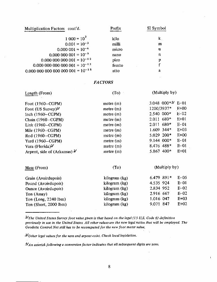
Multiplication Factors contd. Prefix SI Symbol
1 000 103. kilo k
0.001 10-3 milli m0.000 001 10- 6 micro u
0.000 000 00 l 10- 9 nano n
0.000 000 000 001 10-12 Pico p
0.000 000 000 000 001 10-15 femto f
0.000 000 000 000 000 001 10-1s
atto a
FACTORS
Length From To Multiply by
Foot 1960-CGPM metre m 3.048 0004/ E-0l
Foot US Survey metre m 1200/3937 E00Inch 1960CGPM metre m 2.540 000 E-02
Chain 1960-CGPM metre m 2.011 680 EOlLink 1960-CGPM metre m 2.011 680 E-01
Mile 1960-CGPM metre m 1.609 344 E03Rod 1960-CGPM metre m 5.029 200 E00Yard 1960-CGPM metre m 9.144 000 E-01
Vara Florida/ metrem 8.476 488 E-01
Arpent side of Arkansas / metre m 5.867 400 E01
Mass From To Multiply by
Grain Avoirdupois kilogram kg 6.479 891 E- 05
Pound Avoirdupois kilogram kg 4.535 924 E-0l
Ounce Avoirdupois kilogram kg 2.834 952 E-02
Ton Assay kilogram kg 2.916 667 E- 02
Ton Long 2240 lbm kilogram kg 1.016 047 E03Ton Short 20001bm kilogram kg 9.071 847 E02
The United States Survey foot value given is that based on the legal15 U.S. Code 6 definition
previously in use in the United States. All other values are the new legal ratios that will be employed. The
Geodetic Control Net still has to be recomputed for the new foot meter value.
-Other legal values for the vara and arpent exist. Check local legislation.
JAn asterisk following a conversion factor indicates that all subsequent digits are zero.
8

Pressure From To Multiply by
Inch of mercury 60F newton/metre2 N/m2 3.376 85 E03PSI newton/metre2 N/m2 6.894 757 E03
Temperature From To Multiply by
Degree Celsius Kelvin K tk tc 273.15
Degree Fahrenheit degree Celsius tc tf - 32/1.8
Degree Kelvin degree Celsius tc tk - 273.15
Time From To Multiply by
Hour Mean solar second s 3.600 000 E03Hour Sidereal second s 3.590 170 E03Minute Mean solar second s 6.000 000 E01Minute Sidereal second s 5.983 617 E01Second Sidereal second s 9.972 696 E-01
Plane Angles From To Multiply by
Degree angular radian rad. 1.745 329 E-02
Minute angular radian rad. 2.908 882 E- 04
Second angular radian rad. 4.848 137 E- 06
Grad angular radian rad. 1.570 796 E-02
Minute angular degree angular 1/60 E00Second angular degree angular 1/3600 E00Grad angular degree angular 9.000 000 E-01
Area From To Multiply bY
Arpent Arkansas J metre2 m2 3.442 638 E03Acre metre2 m2 4.046 856 E03
JThe unit pascal Pa will be substituted for newton/metre2 N/m2 in the near future.
JThe exact value is 4.046 856 422 E03.
9

Area From contd. To Multiply by
Hectare J metre2 m2 1.000 000 E04Foot 2 metre2 m2 9.290 304 E- 02
Inch 2 metre2 m2 6.451 600 E- 04
Mile 2 metre2 m2 2.589 988 E06Chain 2 metre2 m2 4.046 856 E02Section metre2 m2 2.589 988 E06Township metre2 m2 9.323 957 E07Rod metre2 m2 2.529 084 EO 1
Yard metre2 m2 8.361 274 E-01
Volume From To Multiply by
Acre-Foot metre3 m3 1.233 482 E03Board-Foot metre3 m3 2.359 737 E-03
Foot 3 metre3 m3 2.957 353 E-05
Gallon U. S. Liquid metre3 m3 3.785 412 E- 03
Yard 3 metre3 m3 7.645 549 E-01
Liter metre3 m3 1.000 000 E- 03
Flow From To Multiply by
Foot 3/second metre3 /second m3/s/s 2.831 685 E- 02
Miscellaneous From To Multiply by
Fathom metre m 1.828 800 E00Cable metre m 2.194 560 E02Mile nautical metre m 1.852 000 E03Palm metre m 7.620 000 E-02
Hand metre m 1.016 000 E-01
Span metrem 1.524 000 E-01
Cubit metre m 4.572 000 E-01
Cubit Biblical metrem 5.537 2 E-01
Pace Military metre m 7.62 E-01
JSince the SI System recommends prefixes for the exponential values of ten that are multiples plus or
minus of three the hectare like the angstrom is not used. For larger areas use kilometer2 Km2 or
megameter2 Mm2.
10

EXAMPLES
The factor for converting 1 inch to 1 metre is listed as 2.540 000 E-02. This factor equals
2.54 X 10⁻² exactly or 0.0254 exactly. Rules for mathematics regarding accuracy
precision significant digits rounding and notation can be found in greater detail in ASTME380-72.
11

WASHINGTON OFFICE DIVISION OF ENGINEERING NEWS
OPERA TIONS
Harold L. Strickland
Assistant Director
Visible But Not Seen
Yes they. are there but how much attention did you pay to them What The National
Forest boundaries and the geographic names on that map you recently used.
How about someof those Forest Economics and Marketing Research publications
Outlook for Timber in the United States formerly Timber Trends and Demand and
Price
There are write-ups of special studies too like wild and scenic rivers conversion ofprim-itiveareas to wilderness areas roadless area review eastern wilderness studies etc. all of
which have graphs charts and illustrations. Perhaps you have been involved in theprepara-tionof some of these.
Before long there will be a new poster-and-small-metal-sign catalog with illustrations of all
Forest Service signs.
Have you ever considered the need for accuracy in the portrayal of the Forest Service
boundaries or the geographic names shown on the maps we publish or how those graphics
came to be in the report
The Cartographic unit in the WO Division of EngineeringOperations group represents the
Department of Agriculture on the Board of Geographic Names to insure that geographic
names shown on our maps are accurate and to provide the Board with informationconcern-ingcorrect geographic names.
The Cartographic unit maintains the official atlases showing each National Forest boundary
and boundary changes. Before all Forest Series maps are published they are edited for
general format National Forest boundaries and geographic names by personnel in this unit.
Records are also maintained by this unit for the publication Establishment andModifi-cationof National Forest Boundaries.
12

The Cartographic unit also prepares special maps for members of Congress showing Forest
Service conditions. They also prepare charts graphs covers maps botanical drawings and
other special illustrative material for the publications mentioned earlier as well as for the
publications of the WO Divisions of Timber Management Research Lands Fire Management
Cooperative Forest Fire Control and others.
Lew Glover heads this Cartographic unit. His principal assistant Ed Marshall is responsible
for boundaries and atlas maintenance. Robert Driskell is the representative to the Board of
Geographic Names. Hazel Hartman Monroe Weston Josephine Davis and Marjory Herfurth
add their special talents to complete the illustrations needed for publications like those
mentioned above.
TECHNOLOGICAL IMPROVEMENTS
Heyward T. Taylor
Assistant Director of Engineering
Computer Generated Graphics
Resource managers planners interdisciplinary teams and private citizens will probably all
agree with Confucius that one picture is worth a thousand words. Computer programs are
now available on the UNIVAC 1108 for displaying a perspective view of a section of aroad-wayon a photograph. This procedure will help diverse groups of people visualize therela-tionshipof a proposed road to the terrain. These computer-generated perspective plots on
photographs are highly effective information sources. This procedure will help the user
understand how the proposed road or an improvement to an existing road will affectnear-byresources. For example one can actually see how close the proposed road will be to an
eagles nest a group of aspen trees a meadow a salmon spawning ground or a barn. Byusing computer-generated graphics for these situations there are ample opportunities for
locating changes well in advance of any construction staking.
EDITORS NOTE Our display board outside the Directorss Office is ready for a change Do you have a
display of an engineering project which you would be willing to loan us for awhile
We have many visitors to the Division including some from foreign countries. This display would be an
excellent opportunity for you to visibly introduce your favorite project.
If you have a display you would like shown please let us know.
13

Region 2 personnel have been testing the computer program and graphic procedures for
several months. They are enthused with the possibilities of the program and will bereport-ingon their experiences in a forthcoming article in Field Notes.
CONSUL TA TIONAND STANDARDS
Charles R. Weller
Assistant Director
Transportation Information System. A Service-wide work group recently met to complete
design of format and data characteristics. The Transportation System Planning Project
TSPP has been assigned responsibility for developing the system which we hope will be
ready for initial use by late next year. Regions will be kept informed of progress and asked
to review and test various elements of the system as they are completed.
Traffic Surveillance Handbook. This handbook has been published in manuscript form and
distributed to Regions and Forests. Any Forest desiring assistance in planning and designing
a traffic surveillance project should contact TSPP.
Road Operations. A renewed effort is being made to develop and adopt a Service-wide
cooperative road maintenance agreement for cost-share agreement areas and other situations
where maintenance is a shared responsibility between commercial users and the government.
The Washington Office Engineering and Lands plans an early review of the cost-share road
program as a result of a study team problem analysis made by Region 1.
We are receiving many recurring questions concerning the applicability of CFR 212 to
specific traffic regulation needs. These questions indicate that new or revised regulations
may be necessary to satisfy present and future traffic management objectives.
000000000
14 GPO 869.210


