engineering study ore otat a ad storae vaato
TRANSCRIPT

Prepared for:
Chlorine Contact Tank and Storage Evaluation
September 2014
ENGINEERING STUDY
WBG081114062159MKE
©2014 Google
OAK CREEKWATER AND SEWER UTILITY
A COMMITMENT TO WATER QUALITY
Prepared by:
PSC REF#:232569Public Service Commission of Wisconsin
RECEIVED: 03/02/15, 9:59:00 AM
Eng inee r i ng S tudy
Chlorine Contact Tank and Storage Evaluation
Prepared for Oak Creek Water and Sewer Utility
Oak Creek, Wisconsin
September 2014
135 S. 84th Street
Suite 400 Milwaukee, WI 53214

WBG081114062159MKE II
Executive Summary Purpose The purpose of the Oak Creek water plant chlorine contact tank and storage evaluation project is to evaluate alternatives for the water plant chlorine contact tank to meet current codes. In addition, alternatives were evaluated to provide finished water storage at the plant site and related pumping improvements (intermediate and high lift pump stations). Alternatives for enhancement of the disinfection process were also evaluated.
Background The Oak Creek Water and Sewer Utility provides retail drinking water service to the City of Oak Creek. Drinking water is sold wholesale to the City of Franklin as well as to the Caledonia Utility District.
The source of drinking water is Lake Michigan. A pump station near the lake conveys raw water to a treatment plant. Water is treated in a conventional surface water treatment plant with a treatment capacity of 35 million gallons per day. The filtered water passes through a baffled chlorine contact tank before being pumped to customers. The chlorine contact tank provides primary disinfection in accordance with the surface water treatment rule. The chlorine contact tank was originally used for finished water storage. In 1997 it was baffled and converted into a chlorine contact tank to meet surface water treatment regulations for disinfection. In order to meet disinfection regulations, the water level in the chlorine contact tank needs to remain high. Therefore, there is little to no usable finished water storage at the water plant.
Wisconsin Department of Natural Resources (WDNR) has stated that the chlorine contact tank does not meet current codes (NR 811), and that this must be addressed within 10 years (by 2018). Alternatives for complying with these current codes are evaluated in this report.
The Oak Creek water plant does not have finished water storage at the water plant site. This reduces operational flexibility and reliability as water demands change or if treatment capacity is reduced. Alternatives for storage at the plant are also addressed in this report.
The WDNR requires new storage tanks to be above groundwater levels. Given the current hydraulics of the water plant, pumping is required with aboveground storage tanks. An intermediate pumping station (IPS) is evaluated in this report. In addition, the high lift pump station (HLPS) that delivers water to customers is about 40 years old and showing signs of age. A typical useful life for pumps is about 30 years. The Utility has done a good job of maintaining these pumps to extend their useful life. Alternatives to rehabilitate, modify, or replace this pump station are evaluated.
The Utility uses chlorine as the primary disinfectant, and distribution system disinfectant. The Utility meets all current drinking water regulations and produces high quality water. Many water utilities employ additional barriers to pathogens, particularly Cryptosporidium. Chlorine does not kill Cryptosporidium. Continued monitoring for Cryptosporidium per drinking water regulations (Long‐Term 2 Enhanced Surface Water Treatment Rule) could result in future regulatory requirements to add a Cryptosporidium barrier (see Section 1‐ Background for additional information on this regulation). The next round of Cryptosporidium monitoring is in 2016. Additional pathogen barriers include ozone, membrane filtration, and ultraviolet light (UV) disinfection. Most water utilities on the west shore of Lake Michigan have one of these additional pathogen barriers. This study looks at the costs and benefits of adding UV disinfection or membrane filtration as an additional pathogen barrier to the Oak Creek water plant.
This report describes the evaluation of alternatives for the chlorine contact tank, water storage, pumping and enhanced disinfection at the water plant. This report was a team effort with Utility staff, WDNR, and CH2M HILL. Ideas from all parties were valuable and improved the final recommendations of this report.

EXECUTIVE SUMMARY
WBG081114062159MKE III
Goals The following project goals were developed.
Address WDNR concerns for chlorine contact tank code compliance and lack of water storage.
Further improve water quality and public health protection.
Improve operational efficiency and reliability at the water plant and its pumping systems
Provide flexibility to take a chlorine contact tank offline for inspection, as required by WDNR code, while keeping the plant running.
Consider future water demands when new or modified facilities are evaluated so that future expansion can be effectively implemented.
Alternatives Eight alternatives were evaluated to address the chlorine contact tank, storage, disinfection and pumping systems at the Oak Creek water plant. The alternatives included combinations of the following facilities:
Modified existing chlorine contact tank to meet current codes
A new IPS, or modified existing HLPS into an IPS
A new UV light disinfection facility
A new membrane filtration facility
New aboveground storage tanks
A new HLPS, or modified existing HLPS for use with the new aboveground storage
All alternatives would include bringing the existing chlorine contact tank up to current codes, a new or modified IPS, new storage, new or modified HLPS, and electrical improvements. The alternatives assume that the water plant capacity will be 35 million gallons per day. The alternatives are listed below:
1—Double wall the chlorine contact tank and raise roof, new IPS, new storage, use existing HLPS.
1A—Double wall chlorine contact tank and raise roof, new HLPS, new storage, modify HLPS to IPS.
2—Raise chlorine contact tank roof, new IPS, UV, new storage, use existing HLPS.
2A—Raise chlorine contact tank roof, modify HLPS to IPS, UV, new storage, new HLPS.
3—Raise chlorine contact tank roof, new IPS, membranes, new storage, use existing HLPS.
3A—Raise chlorine contact tank roof, modified HLPS to IPS, membranes, new storage, new HLPS.
4—Raise chlorine contact tank roof, new IPS, UV, new storage, new HLPS. (IPS and UV near the plant).
4A—Raise chlorine contact tank roof, new IPS, UV, new storage, new HLPS. (IPS and UV away from the plant).
Alternatives Evaluation Team members from the Utility, CH2M HILL, and WDNR determined the important criteria to be used to evaluate the alternatives. The following evaluation criteria were established:
Water Quality—Improvement in water quality and public health protection. Meeting current and future drinking water regulations.
Water Quantity—The ability to provide increased capacity now or in the future for the current service area. Elimination of hydraulic bottlenecks.
Operation and Maintenance (O&M)—Ease and complexity of O&M. Flexibility to take facilities offline. Improving the reliability of the water production system. Eliminating single points of failure.
Constructability—Ease of construction and ability to keep the existing plant operational during construction. Number of tie‐ins to existing facilities. Sequencing of construction required.
EXECUTIVE SUMMARY
WBG081114062159MKE IV
Future Expansion—The ability to provide increased capacity in the future for new customers not in the existing service area. Land area available and ease of expanding facilities.
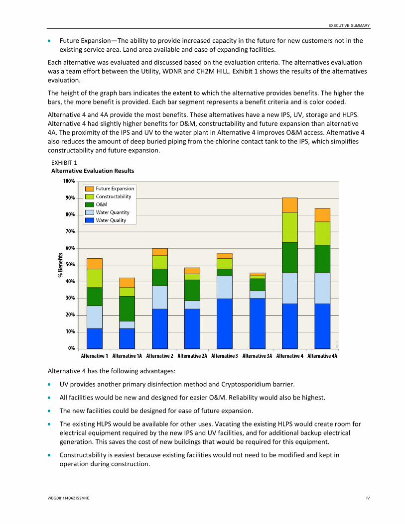
Each alternative was evaluated and discussed based on the evaluation criteria. The alternatives evaluation was a team effort between the Utility, WDNR and CH2M HILL. Exhibit 1 shows the results of the alternatives evaluation.
The height of the graph bars indicates the extent to which the alternative provides benefits. The higher the bars, the more benefit is provided. Each bar segment represents a benefit criteria and is color coded.
Alternative 4 and 4A provide the most benefits. These alternatives have a new IPS, UV, storage and HLPS. Alternative 4 had slightly higher benefits for O&M, constructability and future expansion than alternative 4A. The proximity of the IPS and UV to the water plant in Alternative 4 improves O&M access. Alternative 4 also reduces the amount of deep buried piping from the chlorine contact tank to the IPS, which simplifies constructability and future expansion.
EXHIBIT 1 Alternative Evaluation Results
Alternative 4 has the following advantages:
UV provides another primary disinfection method and Cryptosporidium barrier.
All facilities would be new and designed for easier O&M. Reliability would also be highest.
The new facilities could be designed for ease of future expansion.
The existing HLPS would be available for other uses. Vacating the existing HLPS would create room for electrical equipment required by the new IPS and UV facilities, and for additional backup electrical generation. This saves the cost of new buildings that would be required for this equipment.
Constructability is easiest because existing facilities would not need to be modified and kept in operation during construction.

EXECUTIVE SUMMARY
WBG081114062159MKE V
Cost Estimates Exhibit 2 summarizes the estimated construction costs, annual O&M costs, and net present worth for each alternative. These conceptual cost estimates were prepared for the purpose of comparison of alternatives.
Costs and benefits are summarized in Exhibit 3.
The membrane alternatives (3 and 3A) have much greater costs than the other alternatives. Since the membrane alternatives do not provide greater benefits, those alternatives were not considered any further.
Alternatives 1 and 1A have the lowest costs but also low benefits. There is no additional pathogen barrier, and the existing chlorine contact tank, though modified, remains in place and must be monitored continuously for leakage because it remains below groundwater.
Alternative 2 has the second highest benefit (60 percent) compared to Alternative 4 (90 percent), and is about $2 million lower in construction cost. The main disadvantage of Alternative 2 is modification of the existing HLPS to operate with a new aboveground storage tank. Construction and future expansion of the HLPS will be much more difficult because of its location near existing buildings and depth below ground (greater than 30 feet). Water plant operations and service to customers during construction will be more difficult because at least half the pumping capacity will be out of service while construction is being done. Currently the HLPS has a water reservoir below ground where water is pumped from. Plant hydraulics limit this water level to below the floor of the HLPS. The new storage tank water level would be about 20 to 30 feet above the floor of the HLPS, creating a condition where a leak could cause flooding of the HLPS. In addition, the HLPS cannot be used for other purposes, such as housing electrical gear and generation equipment, or chemical systems. Use of the HLPS building for other purposes provides a cost advantage.
EXHIBIT 2 Alternatives Cost Estimate Summary
Alternative
Construction Cost Estimate ($ million)
Additional Annual O&M Cost ($ million)
20 yr. Net Present Value ($ million)
1—Double wall chlorine contact tank, new IPS, new storage, existing HLPS. $14.6 $0.07 $16 1A—Double wall chlorine contact tank, new HLPS, new storage, modified HLPS to IPS.
$16.2 $0.07 $17
2—Raise chlorine contact tank roof, new IPS, UV, new storage, existing HLPS. $18.6 $0.12 $20 2A—Raise chlorine contact tank roof, modify HLPS to IPS, UV, new storage, new HLPS.
$20.1 $0.12 $22
3—Raise chlorine contact tank roof, new IPS, membranes, new storage, use existing HLPS.
$51.1 $0.39 $57
3A—Raise chlorine contact tank roof, modified HLPS to IPS, membranes, new storage, new HLPS.
$52.5 $0.39 $59
4—Raise chlorine contact tank roof, new IPS, UV, new storage, new HLPS. (IPS and UV near the plant).
$20.7 $0.12 $23
4A—Raise chlorine contact tank roof, new IPS, UV, new storage, new HLPS. (IPS and UV away from the plant).
$21.2 $0.12 $23

EXECUTIVE SUMMARY
WBG081114062159MKE VI
EXHIBIT 3 Cost and Benefit Summary
Selected Alternative Alternative 4 is the selected alternative, because it provides the most benefits in all categories (50 percent more benefit score than the next highest alternative) and is only 10 percent higher in construction cost than the next highest benefit alternative. The higher construction cost is justified by:
New, more reliable facilities designed for the intended purpose
Easier O&M and longer life with all new facilities.
Simpler and less risky construction, and more reliable operations during construction
Better flexibility for future expansion and ability to use the HLPS for other beneficial uses.
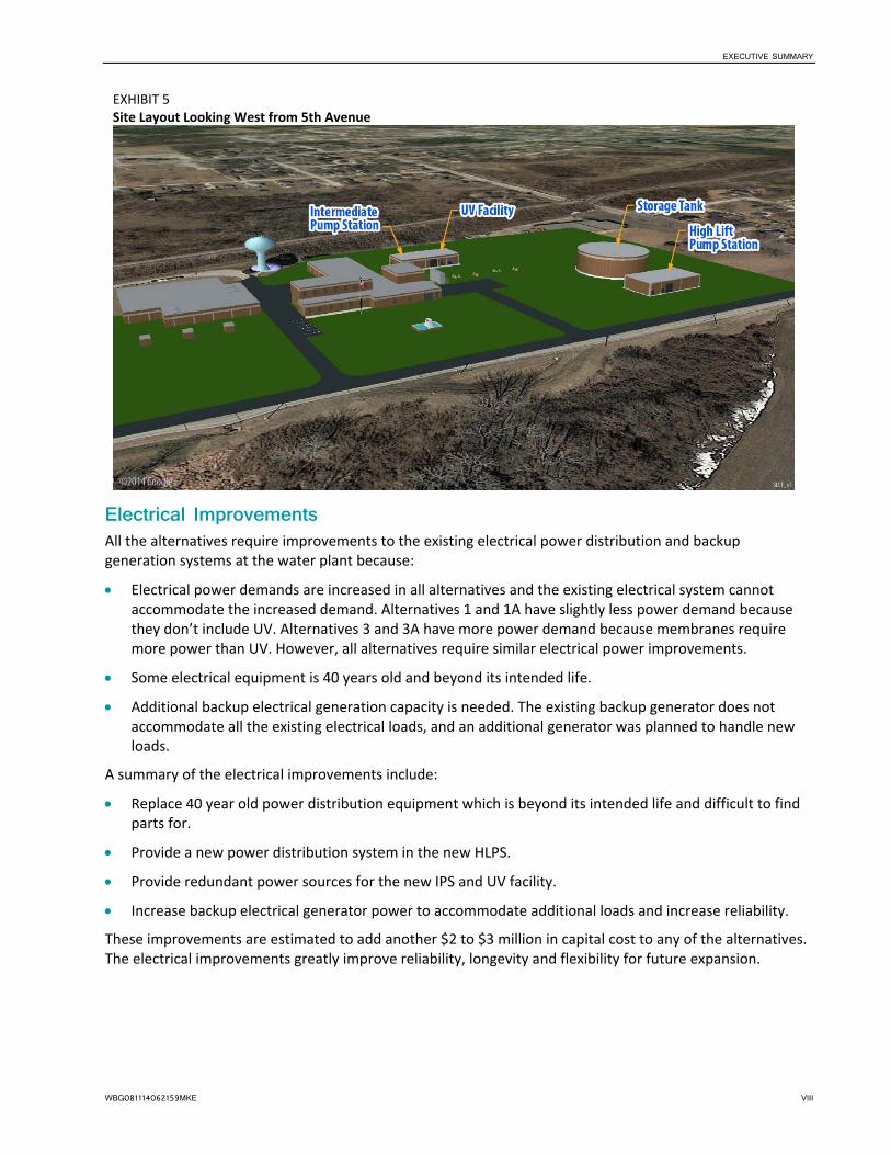
A site plan showing location of the facilities for Alternative 4 is in Exhibit 4. A schematic rendering of the water plant site with the new facilities is shown in Exhibit 5.
After further analysis and discussions with Utility staff, bypassing the chlorine contact tank instead of keeping it in service is the preferred scenario. This can save $600,000 by not having to raise the chlorine contact tank roof, and future O&M of the chlorine contact tank is eliminated. The chlorine contact tank can be demolished in the future, if the space is needed. The double pathogen disinfection barrier of chlorine and UV is maintained in this scenario because the new storage tank has chlorine contact capability.

© CH2M HILL
460402
EE
E
E
EE
E
E
E
E
EE
E
E E EE E E
RW
RW
RW
E
E
EE
E
RW
RW
RWRW
RW
RW
RWSBS
SBS
SB
SS
BS
SD
W1
W1
WWW
WW
RIPRAP
CB
C
S
S
S
S
S
S
SS
SS
SS
S
S
SS
S
SD
SD
SD
SD
SSSS SS
SS
SS
SW
SW
SW
W1
SD SD SDSD SD SD
SD
SD
SD
SD
SD
SD
SD
SD
SD
SD
SD
SD
SS SS SS
SS
SS
SS
SS
SS
SS
FE
FE
FE
W W W W W
W
W
W W W
W W
W
W
W W
W
WW
W
W
WW
W
W
WW
WW
W
W
W
W
W
W
W
W
W
W
W
W
G
GG
G
G
GG
G
CB CB
CB
D D
D
D
D
D
D
D
D
D
D
D
CB
W
W
W
W
W
W
W
W
CHICAGO AND NORTHWESTERN TRANSPORTATION COMPANY
FILTRATION FACILITY
ADMINISTRATION AND
FILTERS 1-6
CHLORINE CONTACT TANK
FILTERS 7-10
N
0 40 80
Scale In Feet
24" RW
60" SW FILTERS 11-14
BASIN
RECOVERY
BACKWASH
18" SS
1" G
48" RW
12" SD
8" SS
FACILITY
PRETREATMENT
CULVERT
30" RCP
POOL
SIGN/
120
E.
AM
ERIC
AN A
VE.
SEDIMENTATION BASINS
FLOCCULATION AND
1" W
1" W
6" W1
60" SS
1 1/2" W
4" SD
30" W30" RW
SAMPLE2"
6" SS
1" W
36" RW
PUMP BLDG
SLUDGE
48" RW
6" W1
12" SD
12" SS
12" SD 12" SD
48" SW
TANK
WASH
BACK-
20" BWS
42" FE
4" SD
48" W
BW
30" W
1" SAMPLE
10" RW
30" W
6" SD
24" BWW
12" BWW
18" SD
1" SAMPLE
30" W
12" SD
1" SAMPLE
S. 5TH AVE.
PUMP STATION
HIGH LIFT
PUMP STATION
INTERMEDIATE
EXHIBIT2-7_460402.DGN
COMPONENTS OF ALTERNATIVE 4
BASIN
RECOVERY
BACKWASH
FUTURE
48" SD
EXHIBIT 2-7
ALTERNATIVE 4
SITE PLAN
STORAGE TANK
FACILITY
UV
AND/OR CHEMICALSGENERATOR
HIGH SERVICE PUMP STATION AVAILABLE FOR6.
NEW HIGH LIFT PUMP STATION5.
NEW STORAGE TANK4.
UV FACILITY3.
NEW INTERMEDIATE PUMP STATION2.
CHLORINE CONTACT TANK ROOF MODIFICATIONS1.
4
EXECUTIVE SUMMARY
WBG081114062159MKE VIII
EXHIBIT 5 Site Layout Looking West from 5th Avenue
Electrical Improvements All the alternatives require improvements to the existing electrical power distribution and backup generation systems at the water plant because:
Electrical power demands are increased in all alternatives and the existing electrical system cannot accommodate the increased demand. Alternatives 1 and 1A have slightly less power demand because they don’t include UV. Alternatives 3 and 3A have more power demand because membranes require more power than UV. However, all alternatives require similar electrical power improvements.
Some electrical equipment is 40 years old and beyond its intended life.
Additional backup electrical generation capacity is needed. The existing backup generator does not accommodate all the existing electrical loads, and an additional generator was planned to handle new loads.
A summary of the electrical improvements include:
Replace 40 year old power distribution equipment which is beyond its intended life and difficult to find parts for.
Provide a new power distribution system in the new HLPS.
Provide redundant power sources for the new IPS and UV facility.
Increase backup electrical generator power to accommodate additional loads and increase reliability.
These improvements are estimated to add another $2 to $3 million in capital cost to any of the alternatives. The electrical improvements greatly improve reliability, longevity and flexibility for future expansion.

WBG081114062159MKE IX
Acknowledgments We appreciate the insights, ideas, teamwork and support of the following individuals who contributed to this project.
Oak Creek Water and Sewer Utility Mike Sullivan, General Manager Ron Pritzlaff, P.E., Utility Engineer Patrick Francis, Water Plant Manager
Wisconsin Department of Natural Resources Larry Landsness, Water Supply Engineer, Public Water Engineering Section, Bureau of Drinking Water & Groundwater Steve Szymaszek, Water Supply Engineer, South District, Bureau of Drinking Water & Groundwater

WBG081114062159MKE X
Contents Executive Summary ................................................................................................................................... ii
Acknowledgments ..................................................................................................................................... ix
Acronyms and Abbreviations .................................................................................................................... xii
1 Introduction ............................................................................................................................... 1‐1 Purpose ............................................................................................................................................... 1‐1 Background ......................................................................................................................................... 1‐1 Goals ................................................................................................................................................... 1‐2 Scope of Work ..................................................................................................................................... 1‐3
Task 1—Frame the Issues and Develop Goals ....................................................................... 1‐3 Task 2—Develop Alternatives ................................................................................................ 1‐3 Task 3—Evaluate Alternatives ............................................................................................... 1‐3 Task 4—Cost Estimates .......................................................................................................... 1‐3 Task 5—Recommendations ................................................................................................... 1‐3 Task 6—Report ....................................................................................................................... 1‐3
2 Alternatives Analysis .................................................................................................................. 2‐1 Alternatives Description ..................................................................................................................... 2‐1
Alternative 1 .......................................................................................................................... 2‐1 Alternative 1A ........................................................................................................................ 2‐1 Alternative 2 .......................................................................................................................... 2‐4 Alternative 2A ........................................................................................................................ 2‐4 Alternative 3 .......................................................................................................................... 2‐7 Alternative 3A ........................................................................................................................ 2‐7 Alternative 4 ........................................................................................................................ 2‐10
Alternatives Comparison .................................................................................................................. 2‐13 Alternatives Evaluation ..................................................................................................................... 2‐13
Water Quality ....................................................................................................................... 2‐15 Water Quantity .................................................................................................................... 2‐15 Operation and Maintenance ................................................................................................ 2‐15 Constructability .................................................................................................................... 2‐15 Future Flexibility .................................................................................................................. 2‐16
Cost Estimates ................................................................................................................................... 2‐16 Construction Cost Estimates ................................................................................................ 2‐16 Estimated Life‐Cycle Costs ................................................................................................... 2‐16
3 Selected Alternative ................................................................................................................... 3‐1 Site Plan .............................................................................................................................................. 3‐1 Facilities for Alternative 4 ................................................................................................................... 3‐2
Chlorine Disinfection .............................................................................................................. 3‐2 Intermediate Pump Station ................................................................................................... 3‐2 UV Disinfection ...................................................................................................................... 3‐4 Storage ................................................................................................................................... 3‐6 High Lift Pump Station ......................................................................................................... 3‐10
Alternative 4 Disinfection Scenarios ................................................................................................. 3‐12 Hydraulics .......................................................................................................................................... 3‐13
Purpose ................................................................................................................................ 3‐13

CONTENTS
WBG081114062159MKE XI
Approach .............................................................................................................................. 3‐13 Analysis Results .................................................................................................................... 3‐14
Electrical ............................................................................................................................................ 3‐16 Existing Electrical Infrastructure .......................................................................................... 3‐16 New Electrical Loads and Facilities ...................................................................................... 3‐18 Improvements to Existing Electrical System ........................................................................ 3‐18 Future Expansion Capabilities .............................................................................................. 3‐21 Backup Generator Considerations ....................................................................................... 3‐21 Summary of Electrical Improvements.................................................................................. 3‐21
Exhibits
1 Alternative Evaluation Results ............................................................................................................... iv 2 Alternatives Cost Estimate Summary ..................................................................................................... v 3 Cost and Benefit Summary .................................................................................................................... vi 4 Site Development Plan: Alternative 4 ................................................................................................... vii 5 Site Layout Looking West from 5th Avenue ........................................................................................ viii 1‐1 Bin Classification for Filtered Systems ................................................................................................ 1‐2 2‐1 Site Development Plan: Alternative 1 ................................................................................................. 2‐2 2‐2 Site Development Plan: Alternative 1A .............................................................................................. 2‐3 2‐3 Site Development Plan: Alternative 2 ................................................................................................. 2‐5 2‐4 Site Development Plan: Alternative 2A .............................................................................................. 2‐6 2‐5 Site Development Plan: Alternative 3 ................................................................................................. 2‐8 2‐6 Site Development Plan: Alternative 3A .............................................................................................. 2‐9 2‐7 Site Development Plan: Alternative 4 ............................................................................................... 2‐11 2‐8 Site Development Plan: Alternative 4A ............................................................................................ 2‐12 2‐9 Alternative Advantages and Disadvantages ..................................................................................... 2‐13 2‐10 Evaluation Criteria Weighting ........................................................................................................... 2‐14 2‐11 Alternative Evaluation Results .......................................................................................................... 2‐14 2‐12 Alternatives Cost Estimate Summary ............................................................................................... 2‐17 2‐13 Alternative Cost and Benefit Summary ............................................................................................ 2‐18 3‐1 Site Layout with Circular Storage Tank ............................................................................................... 3‐1 3‐2 Site Layout with Rectangular Storage Tank ........................................................................................ 3‐2 3‐3 Design Criteria for Intermediate Pump Station .................................................................................. 3‐3 3‐4 Intermediate Pump Station and UV Schematic .................................................................................. 3‐3 3‐5 Water Plant Site with IPS and UV Facility ........................................................................................... 3‐4 3‐6 UV Reactor .......................................................................................................................................... 3‐5 3‐7 Water Plant UV Installation ................................................................................................................ 3‐5 3‐8 Design Criteria for UV Disinfection System ......................................................................................... 3‐5 3‐9 Potable Water Storage Design Requirements .................................................................................... 3‐8 3‐10 Comparison of Storage Tank Alternatives ........................................................................................ 3‐10 3‐11 Design Criteria for High Lift Pump Station ........................................................................................ 3‐10 3‐12 High Lift Pump Station Schematic ..................................................................................................... 3‐11 3‐13 High Lift Pump Station View on Plant Site ........................................................................................ 3‐11 3‐14 Disinfection Scenarios ....................................................................................................................... 3‐12 3‐15 Hydraulic Profile ................................................................................................................................ 3‐15 3‐16 Power One‐Line Diagram Demolition ............................................................................................... 3‐17 3‐17 Power On‐Line Diagram .................................................................................................................... 3‐20 3‐18 Electrical Upgrade Summary ............................................................................................................. 3‐22

WBG081114062159MKE XII
Acronyms and Abbreviations A ampere ATS automatic transfer switch ETAP electrical transient analysis program GEN generator HLPS high lift pump station hp horsepower HVAC heating, ventilation, air conditioning IPS intermediate pump station kV kilovolt kVA kilovolt amp kW kilowatt kWh kilowatt‐hour LT2ESWTR Long Term 2 Enhanced Surface Water Treatment Rule MCC motor control center MG million gallons mgd million gallons per day nm nanometer NTU nephelometric turbidity unit O&M operation and maintenance PPE personal protective equipment USS unit substation UV ultraviolet V volt VA volt amp VFD variable frequency drive WDNR Wisconsin Department of Natural Resources XFMR transformer

WBG081114062159MKE 1-1
CHAPTER 1
Introduction Purpose The purpose of the Oak Creek water plant chlorine contact tank and storage evaluation project is to evaluate alternatives for the water plant chlorine contact tank to meet current codes. In addition, alternatives were evaluated to provide finished water storage at the plant site and related pumping improvements (intermediate and high lift pump stations). Alternatives for enhancement of the disinfection process were also evaluated.
Background The Oak Creek Water and Sewer Utility provides retail drinking water service to the City of Oak Creek. Drinking water is sold wholesale to the City of Franklin and to the Caledonia Utility District.
The source of drinking water is Lake Michigan. A pump station near the lake conveys raw water to a treatment plant. Water is treated in a conventional surface water treatment plant with a treatment capacity of 35 million gallons per day. The filtered water passes through a baffled chlorine contact tank before being pumped to customers. The chlorine contact tank provides primary disinfection in accordance with the surface water treatment rule. The chlorine contact tank was originally used for finished water storage. In 1997 it was baffled and converted into a chlorine contact tank to meet surface water treatment regulations for disinfection. To meet disinfection regulations, the water level in the chlorine contact tank needs to remain high. Therefore, there is little to no usable finished water storage at the water plant.
In e‐mail correspondence in 2008, the Wisconsin Department of Natural Resources (WDNR) stated that the chlorine contact tank at the Oak Creek water plant is not meeting current codes, and that the issue must be addressed within 10 years (by 2018).
In the 2012 WDNR Sanitary Survey, the chlorine contact tank was identified as a nonconforming feature, meaning it would no longer be approved by code and should be changed the next time the water system is changed. The following features of the chlorine contact tank are nonconforming:
There is no overflow, as required by Wisconsin Administrative code NR 811.64 (4).
The tank roof is below grade. NR 811. 63 (6) requires that the roof be 2 feet above grade.
The tank roof does not have a flexible membrane covering, per NR 811.64.10 (e).
The tank cannot be taken out of service for inspection or repair without stopping water treatment, since all flow must go through the tank for disinfection. NR 810.14 requires inspection every 5 years, and the tank must be emptied and inspected at least once every 10 years.
In addition, NR 811.63 (4) requires that the tank floor be at least 2 feet above groundwater level. Based on geotechnical investigations (STS, April 2008), the groundwater is above the bottom of the chlorine contact tank. Furthermore, the piping leaving the chlorine contact tank and entering the high lift pump station (HLPS) is under pressure less than water at ground elevation, which would violate NR 811.37.
In the 2012 Sanitary Survey, WDNR recommended that ultraviolet light (UV) disinfection be considered so that the chlorine contact tank improvements can be done.
The Oak Creek water plant does not have finished water storage at the plant site. This reduces operational flexibility and reliability as water demands change or if treatment capacity is reduced. Alternatives for storage at the plant are also addressed herein.
WDNR requires that new storage tanks be above groundwater levels, preferably with the floor at grade (NR 811.63 (4)). Given the hydraulics of the water plant, pumping is required with aboveground storage

CHAPTER 1—INTRODUCTION
WBG081114062159MKE 1-2
tanks. An intermediate pumping facility is evaluated in the report. In addition, the HLPS is about 40 years old and showing signs of age. Alternatives to rehabilitate, modify, or replace the pump station were evaluated.
The Utility uses chlorine as the primary disinfectant, and distribution system disinfectant. The Utility meets all current drinking water regulations and produces high quality water. Many water utilities employ additional barriers to pathogens, particularly Cryptosporidium. Chlorine does not kill Cryptosporidium. Continued monitoring for Cryptosporidium per drinking water Long‐Term 2 Enhanced Surface Water Treatment Rule (LT2ESWTR) regulations could result in future regulatory requirements to add a Cryptosporidium barrier. The next round of Cryptosporidium monitoring is in 2016.
The LT2ESWTR requires filtered water systems to provide additional treatment for Cryptosporidium based on the level of Cryptosporidium found in the source water (Lake Michigan). Filtered water systems are classified into one of four “Bins” based on the results of their source water monitoring. A second round of source water monitoring is required 6 years after the initial bin classification (year 2016), which could cause a classification to change. The following presents the bin classification for filtered systems.
EXHIBIT 1‐1 Bin Classification for Filtered Systems
Cryptosporidium Concentration (oocysts/L) Bin Classification
Additional Cryptosporidium Treatment Required
< 0.075 Bin 1 No additional treatment required
0.075 to < 1.0 Bin 2 1 log
1.0 to < 3.0 Bin 3 2 log
≥ 3.0 Bin 4 2.5 log
Oak Creek is currently in Bin 1, which does not require additional Cryptosporidium treatment. Future monitoring results could require additional Cryptosporidium treatment.
Additional Cryptosporidium treatment technologies include ozone, membrane filtration, and ultraviolet light (UV) disinfection. Most water utilities on the west shore of Lake Michigan have one of these additional pathogen barriers, even though they are in Bin 1. This study looks at the costs and benefits of adding UV disinfection or membrane filtration as an additional pathogen barrier to the Oak Creek water plant.
This report describes the evaluation of alternatives for the chlorine contact tank, water storage, pumping and enhanced disinfection at the water plant. This report was a team effort with Utility staff, WDNR, and CH2M HILL. Ideas from all parties were valuable and improved the final recommendations of this report.
Goals The following project goals were developed:
Address WDNR concerns for chlorine contact tank code compliance and lack of water storage.
Further improve water quality and public health protection.
Improve operational efficiency and reliability at the water plant and its pumping systems
Provide flexibility to take a chlorine contact tank offline for inspection, as required by WDNR code, while keeping the plant running.
Consider future water demands when new or modified facilities are evaluated so that future expansion can be effectively implemented.

CHAPTER 1—INTRODUCTION
WBG081114062159MKE 1-3
Scope of Work The following tasks make up the scope of work for this project.
Task 1—Frame the Issues and Develop Goals A workshop meeting was held with Oak Creek Water and Sewer Utility to discuss the issues and develop goals for the project. Preliminary alternatives to meet the goals were discussed.
Task 2—Develop Alternatives The preliminary alternatives from Task 1 were further developed, and new alternatives were considered. Conceptual sizing and layout options for the water plant site were developed. Preliminary hydraulics were performed to determine elevations of major structures and pumping requirements.
Task 3—Evaluate Alternatives Alternatives were developed to include preliminary sizing, site layouts, hydraulic and electrical requirements. Storage tank types were reviewed (prestressed concrete, cast‐in‐place) and general preferences determined. The capability of the backup electrical generator was reviewed, and additional capacity for new facilities was determined. A workshop meeting was held to review the alternative and evaluate modifications.
Nonmonetary evaluation criteria were developed and weighted with Oak Creek Water and Sewer Utility and WDNR in a workshop meeting. Nonmonetary criteria include water quality benefits, regulatory compliance, ease of operation and maintenance (O&M), constructability, and continued operation of the water plant. The evaluation criteria were applied to each alternative, and the nonmonetary benefit scores of each were determined.
Task 4—Cost Estimates Preliminary order‐of‐magnitude cost estimates were prepared for each alternative. Cost estimates include construction and annual operating/maintenance costs.
Task 5—Recommendations Using both the evaluation criteria results and cost estimates, the alternative that best meets project goals was selected. A meeting with WDNR will be held to review the selected alternative and obtain its input.
The following information is provided for the selected alternative at each flow rate:
Site plan showing location and size of facilities, major yard piping, roads, and parking.
Plan and section of major facilities (pump stations, UV disinfection, storage tanks) to refine the concept.
Hydraulic profile.
Electrical one‐line diagram showing major electrical improvements required.
Task 6—Report This report was prepared to document the alternatives evaluation, recommendations, design criteria and conceptual layouts. It also provides a preliminary opinion of probable construction costs. The report provides some of the information for a project Engineering Report for submittal and review by the WDNR with plans and specifications. A review meeting was held with the WDNR to describe concepts, design criteria, gather regulatory feedback, and lay the groundwork for future design review approval.

WBG081114062159MKE 2-1
CHAPTER 2
Alternatives Analysis Alternatives Description Eight alternatives were evaluated to improve the chlorine contact tank, storage, disinfection and pumping systems at the Oak Creek water plant. Each alternative is described below.
Alternative 1 In Alternative 1, the existing chlorine contact tank would be modified to meet current codes. This includes installation of a double wall in the bottom and sides of the tank with an air gap (to monitor any leakage), and a new raised roof (approximately 5 to 6 feet higher) with a membrane cover and overflow. This construction would need to be done after the new facilities are built because disinfection regulations cannot be met if the existing chlorine contact tank is taken out of service. Piping into and out of the chlorine contact tank would be double contained to comply with codes. A new intermediate pump station (IPS) after the chlorine contact tank pumps the water to a new storage tank. In all alternatives, this storage tank is about 2 million gallons (MG) capacity (see section 3 for details on sizing), and at least half of it would be baffled to act as a chlorine contact tank in case other disinfection facilities are out of service. The existing HLPS would remain in use, with improvements to the electrical and mechanical systems to replace aging equipment.
Exhibit 2‐1 is a site plan for Alternative 1. The existing HLPS has a wet well below groundwater levels, which does not meet current codes. Plant hydraulics limit the water level in this wet well to below the floor of the HLPS. The water level in the new above ground storage tank would be about 20 to 30 feet higher than the floor of the HLPS. Continued use of the existing HLPS raises the following issues:
The HLPS wet well would need to be modified with suction piping and vertical turbine “can” pumps to reduce flooding potential and to eliminate a potable water tank below groundwater. However, the piping would always be under pressure and a leak could flood the HLPS.
Construction and future expansion of the HLPS will be much more difficult because of its location near existing buildings and depth below ground (over 30 feet).
Water plant operations and service to customers during construction will be more difficult because at least half the pumping capacity will be out of service while construction is being done.
Alternative 1A In Alternative 1A, the chlorine contact tank and associated piping would be modified to meet current codes, similar to Alternative 1. The HLPS would be modified to an IPS. This would include replacing all pumps, piping, and electrical equipment. The HLPS wet well would need to be modified with suction piping and vertical turbine “can” pumps to eliminate a potable water tank below groundwater. The IPS would pump water to a new storage tank. A new HLPS would be located near the new storage tank.
Exhibit 2‐2 is a site plan for Alternative 1A. Construction and future expansion of the HLPS converted to an IPS is more difficult because the HLPS needs to remain operational while a portion is converted to an IPS. In addition, the new HLPS needs to be completed before the IPS can be completed. This will reduce water production capacity during construction. Future expansion of the IPS would be more difficult because there are other facilities around the HLPS.

© CH2M HILL
460402
EE
E
E
EE
E
E
E
E
EE
E
E E EE E E
RW
RW
RW
E
E
EE
E
RW
RW
RWRW
RW
RW
RWSBS
SBS
SB
SS
BS
SD
W1
W1
WWW
WW
RIPRAP
CB
C
S
S
S
S
S
S
SS
SS
SS
S
S
SS
S
SD
SD
SD
SD
SSSS SS
SS
SS
SW
SW
SW
W1
SD SD SDSD SD SD
SD
SD
SD
SD
SD
SD
SD
SD
SD
SD
SD
SD
SS SS SS
SS
SS
SS
SS
SS
SS
FE
FE
FE
W W W W W
W
W
W W W
W W
W
W
W W
W
WW
W
W
WW
W
W
WW
WW
W
W
W
W
W
W
W
W
W
W
W
W
G
GG
G
G
GG
G
CB CB
CB
D D
D
D
D
D
D
D
D
D
D
D
CB
W
W
W
W
W
W
W
W
CHICAGO AND NORTHWESTERN TRANSPORTATION COMPANY
FILTRATION FACILITY
ADMINISTRATION AND
FILTERS 1-6
CHLORINE CONTACT TANK
FILTERS 7-10
N
0 40 80
Scale In Feet
24" RW
60" SW FILTERS 11-14
BASIN
RECOVERY
BACKWASH
18" SS
48" RW
12" SD
8" SS
FACILITY
PRETREATMENT
CULVERT
30" RCP
POOL
SIGN/
120
E.
AM
ERIC
AN A
VE.
SEDIMENTATION BASINS
FLOCCULATION AND
1" W
1" W
6" W1
60" SS
1 1/2" W
4" SD
30" W30" RW
SAMPLE2"
6" SS
1" W
36" RW
PUMP BLDG
SLUDGE
48" RW
6" W1
12" SD
12" SS
12" SD 12" SD
48" SW
TANK
WASH
BACK-
20" BWS
42" FE
4" SD
48" W
BW
30" W
1" SAMPLE
10" RW
30" W
6" SD
24" BWW
12" BWW
18" SD
1" SAMPLE
30" W
12" SD
1" SAMPLE
S. 5TH AVE.
PUMP STATION
INTERMEDIATE
EXHIBIT2-7_460402.DGN
COMPONENTS OF ALTERNATIVE 1
BASIN
RECOVERY
BACKWASH
FUTURE
48" SD
EXHIBIT 2-1
ALTERNATIVE 1
SITE PLAN
STORAGE TANK
NEW HIGH LIFT PUMP STATION4.
NEW STORAGE TANK3.
MODIFY HIGH LIFT PUMP STATION TO INTERMEDIATE 2.
CHLORINE CONTACT TANK REBUILDING1.
1" GSTATION
PUMP
LIFT
HIGH

© CH2M HILL
460402
EE
E
E
EE
E
E
E
E
EE
E
E E EE E E
RW
RW
RW
E
E
EE
E
RW
RW
RWRW
RW
RW
RWSBS
SBS
SB
SS
BS
SD
W1
W1
WWW
WW
RIPRAP
CB
C
S
S
S
S
S
S
SS
SS
SS
S
S
SS
S
SD
SD
SD
SD
SSSS SS
SS
SS
SW
SW
SW
W1
SD SD SDSD SD SD
SD
SD
SD
SD
SD
SD
SD
SD
SD
SD
SD
SD
SS SS SS
SS
SS
SS
SS
SS
SS
FE
FE
FE
W W W W W
W
W
W W W
W W
W
W
W W
W
WW
W
W
WW
W
W
WW
WW
W
W
W
W
W
W
W
W
W
W
W
W
G
GG
G
G
GG
G
CB CB
CB
D D
D
D
D
D
D
D
D
D
D
D
CB
W
W
W
W
W
W
W
W
CHICAGO AND NORTHWESTERN TRANSPORTATION COMPANY
FILTRATION FACILITY
ADMINISTRATION AND
FILTERS 1-6
CHLORINE CONTACT TANK
FILTERS 7-10
N
0 40 80
Scale In Feet
24" RW
60" SW FILTERS 11-14
BASIN
RECOVERY
BACKWASH
18" SS
48" RW
12" SD
8" SS
FACILITY
PRETREATMENT
CULVERT
30" RCP
POOL
SIGN/
120
E.
AM
ERIC
AN A
VE.
SEDIMENTATION BASINS
FLOCCULATION AND
1" W
1" W
6" W1
60" SS
1 1/2" W
4" SD
30" W30" RW
SAMPLE2"
6" SS
1" W
36" RW
PUMP BLDG
SLUDGE
48" RW
6" W1
12" SD
12" SS
12" SD 12" SD
48" SW
TANK
WASH
BACK-
20" BWS
42" FE
4" SD
48" W
30" W
1" SAMPLE
10" RW
30" W
6" SD
24" BWW
12" BWW
18" SD
1" SAMPLE
30" W
12" SD
1" SAMPLE
S. 5TH AVE.
PUMP STATION
HIGH LIFT
EXHIBIT2-7_460402.DGN
COMPONENTS OF ALTERNATIVE 1A
BASIN
RECOVERY
BACKWASH
FUTURE
48" SD
EXHIBIT 2-2
ALTERNATIVE 1A
SITE PLAN
STORAGE TANK
NEW HIGH LIFT PUMP STATION4.
NEW STORAGE TANK3.
MODIFY HIGH LIFT PUMP STATION TO INTERMEDIATE 2.
CHLORINE CONTACT TANK REBUILDING1.
1" GSTATION
PUMP
MEDIATE
INTER-

CHAPTER 2—ALTERNATIVES ANALYSIS
WBG081114062159MKE 2-4
Alternative 2 In Alternative 2, the existing chlorine contact tank would be modified to meet current codes by raising and sloping the roof, and installing a membrane cover and overflow. A new IPS would convey water to a new UV disinfection facility. Having UV disinfection downstream of the chlorine contact tank would eliminate the need to double contain the chlorine contact tank and associated piping. Continuous leak detection in the chlorine contact tank would also be eliminated. After UV treatment, the water would continue to a new storage tank. The existing HLPS would be modified as described in Alternative 1.
Exhibit 2‐3 is a site plan for Alternative 2.
Alternative 2A In Alternative 2A, the chlorine contact tank would be modified to meet current codes by raising and sloping the roof, and installing a membrane cover and overflow similar to alternative 2. The existing HLPS would be modified to an IPS, similar to Alternative 1A. A new UV facility and new HLPS would be located near a new storage tank.
Exhibit 2‐4 is a site plan for Alternative 2A.

© CH2M HILL
460402
EE
E
E
EE
E
E
E
E
EE
E
E E EE E E
RW
RW
RW
E
E
EE
E
RW
RW
RWRW
RW
RW
RWSBS
SBS
SB
SS
BS
SD
W1
W1
WWW
WW
RIPRAP
CB
C
S
S
S
S
S
S
SS
SS
SS
S
S
SS
S
SD
SD
SD
SD
SSSS SS
SS
SS
SW
SW
SW
W1
SD SD SDSD SD SD
SD
SD
SD
SD
SD
SD
SD
SD
SD
SD
SD
SD
SS SS SS
SS
SS
SS
SS
SS
SS
FE
FE
FE
W W W W W
W
W
W W W
W W
W
W
W W
W
WW
W
W
WW
W
W
WW
WW
W
W
W
W
W
W
W
W
W
W
W
W
G
GG
G
G
GG
G
CB CB
CB
D D
D
D
D
D
D
D
D
D
D
D
CB
W
W
W
W
W
W
W
W
CHICAGO AND NORTHWESTERN TRANSPORTATION COMPANY
FILTRATION FACILITY
ADMINISTRATION AND
FILTERS 1-6
CHLORINE CONTACT TANK
FILTERS 7-10
N
0 40 80
Scale In Feet
24" RW
60" SW FILTERS 11-14
BASIN
RECOVERY
BACKWASH
18" SS
48" RW
12" SD
8" SS
FACILITY
PRETREATMENT
CULVERT
30" RCP
POOL
SIGN/
120
E.
AM
ERIC
AN A
VE.
SEDIMENTATION BASINS
FLOCCULATION AND
1" W
1" W
6" W1
60" SS
1 1/2" W
4" SD
30" W30" RW
SAMPLE2"
6" SS
1" W
36" RW
PUMP BLDG
SLUDGE
48" RW
6" W1
12" SD
12" SS
12" SD 12" SD
48" SW
TANK
WASH
BACK-
20" BWS
42" FE
4" SD
48" W
BW
30" W
1" SAMPLE
10" RW
30" W
6" SD
24" BWW
12" BWW
18" SD
1" SAMPLE
30" W
12" SD
1" SAMPLE
S. 5TH AVE.
PUMP STATION
INTERMEDIATE
EXHIBIT2-7_460402.DGN
COMPONENTS OF ALTERNATIVE 2
BASIN
RECOVERY
BACKWASH
FUTURE
48" SD
EXHIBIT 2-3
ALTERNATIVE 2
SITE PLAN
STORAGE TANK
FACILITY
UV
USE EXISTING HIGH LIFT PUMP STATION5.
NEW STORAGE TANK4.
UV FACILITY3.
NEW INTERMEDIATE PUMP STATION2.
CHLORINE CONTACT TANK ROOF MODIFICATIONS1.
1" GSTATION
PUMP
LIFT
HIGH

© CH2M HILL
460402
EE
E
E
EE
E
E
E
E
EE
E
E E EE E E
RW
RW
RW
E
E
EE
E
RW
RW
RWRW
RW
RW
RWSBS
SBS
SB
SS
BS
SD
W1
W1
WWW
WW
RIPRAP
CB
C
S
S
S
S
S
S
SS
SS
SS
S
S
SS
S
SD
SD
SD
SD
SSSS SS
SS
SS
SW
SW
SW
W1
SD SD SDSD SD SD
SD
SD
SD
SD
SD
SD
SD
SD
SD
SD
SD
SD
SS SS SS
SS
SS
SS
SS
SS
SS
FE
FE
FE
W W W W W
W
W
W W W
W W
W
W
W W
W
WW
W
W
WW
W
W
WW
WW
W
W
W
W
W
W
W
W
W
W
W
W
G
GG
G
G
GG
G
CB CB
CB
D D
D
D
D
D
D
D
D
D
D
D
CB
W
W
W
W
W
W
W
W
CHICAGO AND NORTHWESTERN TRANSPORTATION COMPANY
FILTRATION FACILITY
ADMINISTRATION AND
FILTERS 1-6
CHLORINE CONTACT TANK
FILTERS 7-10
N
0 40 80
Scale In Feet
24" RW
60" SW FILTERS 11-14
BASIN
RECOVERY
BACKWASH
18" SS
48" RW
12" SD
8" SS
FACILITY
PRETREATMENT
CULVERT
30" RCP
POOL
SIGN/
120
E.
AM
ERIC
AN A
VE.
SEDIMENTATION BASINS
FLOCCULATION AND
1" W
1" W
6" W1
60" SS
1 1/2" W
4" SD
30" W30" RW
SAMPLE2"
6" SS
1" W
36" RW
PUMP BLDG
SLUDGE
48" RW
6" W1
12" SD
12" SS
12" SD 12" SD
48" SW
TANK
WASH
BACK-
20" BWS
42" FE
4" SD
48" W
30" W
1" SAMPLE
10" RW
30" W
6" SD
24" BWW
12" BWW
18" SD
1" SAMPLE
30" W
12" SD
1" SAMPLE
S. 5TH AVE.
PUMP STATION
HIGH LIFT
EXHIBIT2-7_460402.DGN
COMPONENTS OF ALTERNATIVE 2A
BASIN
RECOVERY
BACKWASH
FUTURE
48" SD
EXHIBIT 2-4
ALTERNATIVE 2A
SITE PLAN
STORAGE TANK
FACILITY
UV
NEW HIGH LIFT PUMP STATION5.
NEW STORAGE TANK4.
UV FACILITY3.
MODIFY HIGH LIFT PUMP STATION TO INTERMEDIATE2.
CHLORINE CONTACT TANK ROOF MODIFICATIONS1.
1" GSTATION
PUMP
MEDIATE
INTER-

CHAPTER 2—ALTERNATIVES ANALYSIS
WBG081114062159MKE 2-7
Alternative 3 In Alternative 3, the chlorine contact tank would be modified to meet current codes by raising and sloping the roof, and installing a membrane cover and overflow. A new IPS would convey water to a new membrane filtration facility. Having membranes downstream of the chlorine contact tank would eliminate the need to double contain the chlorine contact tank and associated piping. Continuous leak detection in the chlorine contact tank would also not be needed. After membrane treatment, the water would continue to a new storage tank. The existing HLPS would be modified as described in Alternative 1. Alternative 3 is similar to Alternative 2, except membrane filtration is used instead of UV.
Exhibit 2‐5 is a site plan for Alternative 3.
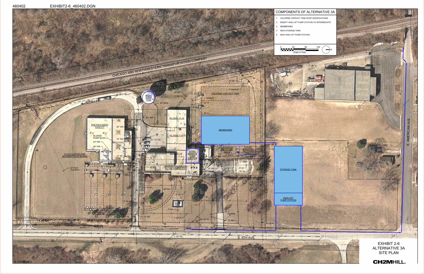
Alternative 3A In Alternative 3A, the chlorine contact tank would be modified to meet current codes by raising and sloping the roof, and installing a membrane cover and overflow. The existing HLPS would be modified to an IPS, similar to Alternatives 1A and 2A. A new membrane filtration facility and new HLPS would be located near a new storage tank. Alternative 3A is similar to Alternative 2A, except membrane filtration is used instead of UV.
Exhibit 2‐6 is a site plan for Alternative 3A.

© CH2M HILL
460402
EE
E
E
EE
E
E
E
E
EE
E
E E EE E E
RW
RW
RW
E
E
EE
E
RW
RW
RWRW
RW
RW
RWSBS
SBS
SB
SS
BS
SD
W1
W1
WWW
WW
RIPRAP
CB
C
S
S
S
S
S
S
SS
SS
SS
S
S
SS
S
SD
SD
SD
SD
SSSS SS
SS
SS
SW
SW
SW
W1
SD SD SDSD SD SD
SD
SD
SD
SD
SD
SD
SD
SD
SD
SD
SD
SD
SS SS SS
SS
SS
SS
SS
SS
SS
FE
FE
FE
W W W W W
W
W
W W W
W W
W
W
W W
W
WW
W
W
WW
W
W
WW
WW
W
W
W
W
W
W
W
W
W
W
W
W
G
GG
G
G
GG
G
CB CB
CB
D D
D
D
D
D
D
D
D
D
D
D
CB
W
W
W
W
W
W
W
W
CHICAGO AND NORTHWESTERN TRANSPORTATION COMPANY
FILTRATION FACILITY
ADMINISTRATION AND
FILTERS 1-6
CHLORINE CONTACT TANK
FILTERS 7-10
N
0 40 80
Scale In Feet
24" RW
60" SW FILTERS 11-14
BASIN
RECOVERY
BACKWASH
18" SS
48" RW
12" SD
8" SS
FACILITY
PRETREATMENT
CULVERT
30" RCP
POOL
SIGN/
120
E.
AM
ERIC
AN A
VE.
SEDIMENTATION BASINS
FLOCCULATION AND
1" W
1" W
6" W1
60" SS
1 1/2" W
4" SD
30" W30" RW
SAMPLE2"
6" SS
1" W
36" RW
PUMP BLDG
SLUDGE
48" RW
6" W1
12" SD
12" SS
12" SD 12" SD
48" SW
TANK
WASH
BACK-
20" BWS
42" FE
4" SD
48" W
30" W
1" SAMPLE
10" RW
30" W
6" SD
24" BWW
12" BWW
30" W
12" SD
1" SAMPLE
S. 5TH AVE.
PUMP STATION
HIGH LIFT
EXHIBIT2-7_460402.DGN
COMPONENTS OF ALTERNATIVE 3
BASIN
RECOVERY
BACKWASH
FUTURE
48" SD
EXHIBIT 2-5
ALTERNATIVE 3
SITE PLAN
STORAGE TANK
USE EXISTING HIGH LIFT PUMP STATION5.
NEW STORAGE TANK4.
MEMBRANES3.
NEW INTERMEDIATE PUMP STATION2.
CHLORINE CONTACT TANK ROOF MODIFICATIONS1.
1" G
STATION
PUMP
MEDIATE
INTER-
STATION
PUMP
LIFT
HIGH
MEMBRANES
BW
1" SAMPLE
18" SD
© CH2M HILL
460402
EE
E
E
EE
E
E
E
E
EE
E
E E EE E E
RW
RW
RW
E
E
EE
E
RW
RW
RWRW
RW
RW
RWSBS
SBS
SB
SS
BS
SD
W1
W1
WWW
WW
RIPRAP
CB
C
S
S
S
S
S
S
SS
SS
SS
S
S
SS
S
SD
SD
SD
SD
SSSS SS
SS
SS
SW
SW
SW
W1
SD SD SDSD SD SD
SD
SD
SD
SD
SD
SD
SD
SD
SD
SD
SD
SD
SS SS SS
SS
SS
SS
SS
SS
SS
FE
FE
FE
W W W W W
W
W
W W W
W W
W
W
W W
W
WW
W
W
WW
W
W
WW
WW
W
W
W
W
W
W
W
W
W
W
W
W
G
GG
G
G
GG
G
CB CB
CB
D D
D
D
D
D
D
D
D
D
D
D
CB
W
W
W
W
W
W
W
W
CHICAGO AND NORTHWESTERN TRANSPORTATION COMPANY
FILTRATION FACILITY
ADMINISTRATION AND
FILTERS 1-6
CHLORINE CONTACT TANK
FILTERS 7-10
N
0 40 80
Scale In Feet
24" RW
60" SW FILTERS 11-14
BASIN
RECOVERY
BACKWASH
18" SS
48" RW
12" SD
8" SS
FACILITY
PRETREATMENT
CULVERT
30" RCP
POOL
SIGN/
120
E.
AM
ERIC
AN A
VE.
SEDIMENTATION BASINS
FLOCCULATION AND
1" W
1" W
6" W1
60" SS
1 1/2" W
4" SD
30" W30" RW
SAMPLE2"
6" SS
1" W
36" RW
PUMP BLDG
SLUDGE
48" RW
6" W1
12" SD
12" SS
12" SD 12" SD
48" SW
TANK
WASH
BACK-
20" BWS
42" FE
4" SD
48" W
30" W
1" SAMPLE
10" RW
30" W
6" SD
24" BWW
12" BWW
30" W
12" SD
1" SAMPLE
S. 5TH AVE.
PUMP STATION
HIGH LIFT
EXHIBIT2-6_460402.DGN
COMPONENTS OF ALTERNATIVE 3A
BASIN
RECOVERY
BACKWASH
FUTURE
48" SD
EXHIBIT 2-6
ALTERNATIVE 3A
SITE PLAN
STORAGE TANK
NEW HIGH LIFT PUMP STATION5.
NEW STORAGE TANK4.
MEMBRANES3.
MODIFY HIGH LIFT PUMP STATION TO INTERMEDIATE2.
CHLORINE CONTACT TANK ROOF MODIFICATIONS1.
1" GSTATION
PUMP
MEDIATE
INTER-
MEMBRANES
18" SD
1" SAMPLE
CHAPTER 2—ALTERNATIVES ANALYSIS
WBG081114062159MKE 2-10
Alternative 4 In Alternative 4, the chlorine contact tank would be modified to meet current codes by raising and sloping the roof, and installing a membrane cover and overflow. There would be a new IPS, new UV, new storage, and a new HLPS. The existing HLPS could be used for other purposes, such as housing new electrical equipment and generator, or chemical feed systems.
Exhibit 2‐7 is a site plan for Alternative 4. The layout has the IPS and UV near the existing plant, and the storage and HLPS to the north on the Utility property. Exhibit 2‐8 shows an alternative layout (Alternative 4A), in which all new facilities would be located on the north site. This location would require longer piping runs, and the piping from the existing chlorine contact tank to the IPS would be longer and much deeper since it would be a gravity line.

© CH2M HILL
460402
EE
E
E
EE
E
E
E
E
EE
E
E E EE E E
RW
RW
RW
E
E
EE
E
RW
RW
RWRW
RW
RW
RWSBS
SBS
SB
SS
BS
SD
W1
W1
WWW
WW
RIPRAP
CB
C
S
S
S
S
S
S
SS
SS
SS
S
S
SS
S
SD
SD
SD
SD
SSSS SS
SS
SS
SW
SW
SW
W1
SD SD SDSD SD SD
SD
SD
SD
SD
SD
SD
SD
SD
SD
SD
SD
SD
SS SS SS
SS
SS
SS
SS
SS
SS
FE
FE
FE
W W W W W
W
W
W W W
W W
W
W
W W
W
WW
W
W
WW
W
W
WW
WW
W
W
W
W
W
W
W
W
W
W
W
W
G
GG
G
G
GG
G
CB CB
CB
D D
D
D
D
D
D
D
D
D
D
D
CB
W
W
W
W
W
W
W
W
CHICAGO AND NORTHWESTERN TRANSPORTATION COMPANY
FILTRATION FACILITY
ADMINISTRATION AND
FILTERS 1-6
CHLORINE CONTACT TANK
FILTERS 7-10
N
0 40 80
Scale In Feet
24" RW
60" SW FILTERS 11-14
BASIN
RECOVERY
BACKWASH
18" SS
1" G
48" RW
12" SD
8" SS
FACILITY
PRETREATMENT
CULVERT
30" RCP
POOL
SIGN/
120
E.
AM
ERIC
AN A
VE.
SEDIMENTATION BASINS
FLOCCULATION AND
1" W
1" W
6" W1
60" SS
1 1/2" W
4" SD
30" W30" RW
SAMPLE2"
6" SS
1" W
36" RW
PUMP BLDG
SLUDGE
48" RW
6" W1
12" SD
12" SS
12" SD 12" SD
48" SW
TANK
WASH
BACK-
20" BWS
42" FE
4" SD
48" W
BW
30" W
1" SAMPLE
10" RW
30" W
6" SD
24" BWW
12" BWW
18" SD
1" SAMPLE
30" W
12" SD
1" SAMPLE
S. 5TH AVE.
PUMP STATION
HIGH LIFT
PUMP STATION
INTERMEDIATE
EXHIBIT2-7_460402.DGN
COMPONENTS OF ALTERNATIVE 4
BASIN
RECOVERY
BACKWASH
FUTURE
48" SD
EXHIBIT 2-7
ALTERNATIVE 4
SITE PLAN
STORAGE TANK
FACILITY
UV
AND/OR CHEMICALSGENERATOR
HIGH SERVICE PUMP STATION AVAILABLE FOR6.
NEW HIGH LIFT PUMP STATION5.
NEW STORAGE TANK4.
UV FACILITY3.
NEW INTERMEDIATE PUMP STATION2.
CHLORINE CONTACT TANK ROOF MODIFICATIONS1.

© CH2M HILL
460402
EE
E
E
EE
E
E
E
E
EE
E
E E EE E E
RW
RW
RW
E
E
EE
E
RW
RW
RWRW
RW
RW
RWSBS
SBS
SB
SS
BS
SD
W1
W1
WWW
WW
RIPRAP
CB
C
S
S
S
S
S
S
SS
SS
SS
S
S
SS
S
SD
SD
SD
SD
SSSS SS
SS
SS
SW
SW
SW
W1
SD SD SDSD SD SD
SD
SD
SD
SD
SD
SD
SD
SD
SD
SD
SD
SD
SS SS SS
SS
SS
SS
SS
SS
SS
FE
FE
FE
W W W W W
W
W
W W W
W W
W
W
W W
W
WW
W
W
WW
W
W
WW
WW
W
W
W
W
W
W
W
W
W
W
W
W
G
GG
G
G
GG
G
CB CB
CB
D D
D
D
D
D
D
D
D
D
D
D
CB
W
W
W
W
W
W
W
W
CHICAGO AND NORTHWESTERN TRANSPORTATION COMPANY
FILTRATION FACILITY
ADMINISTRATION AND
FILTERS 1-6
CHLORINE CONTACT TANK
FILTERS 7-10
N
0 40 80
Scale In Feet
24" RW
60" SW FILTERS 11-14
BASIN
RECOVERY
BACKWASH
18" SS
1" G
48" RW
12" SD
8" SS
FACILITY
PRETREATMENT
CULVERT
30" RCP
POOL
SIGN/
120
E.
AM
ERIC
AN A
VE.
SEDIMENTATION BASINS
FLOCCULATION AND
1" W
1" W
6" W1
60" SS
1 1/2" W
4" SD
30" W30" RW
SAMPLE2"
6" SS
1" W
36" RW
PUMP BLDG
SLUDGE
48" RW
6" W1
12" SD
12" SS
12" SD 12" SD
48" SW
TANK
WASH
BACK-
20" BWS
42" FE
4" SD
48" W
BW
30" W
1" SAMPLE
10" RW
30" W
6" SD
24" BWW
12" BWW
1" SAMPLE
30" W
12" SD
1" SAMPLE
S. 5TH AVE.
PUMP STATION
HIGH LIFT
EXHIBIT2-8_460402.DGN
COMPONENTS OF ALTERNATIVE 4A
BASIN
RECOVERY
BACKWASH
FUTURE
EXHIBIT 2-8
ALTERNATIVE 4A
SITE PLAN
STORAGE TANK
FACILITY
UV
AND/OR CHEMICALSGENERATOR
HIGH SERVICE PUMP STATION AVAILABLE FOR6.
NEW HIGH LIFT PUMP STATION5.
NEW STORAGE TANK4.
UV FACILITY3.
NEW INTERMEDIATE PUMP STATION2.
CHLORINE CONTACT TANK ROOF MODIFICATIONS1.
48" SD
18" SD
BW
STATION
PUMP
MEDIATE
INTER-

CHAPTER 2—ALTERNATIVES ANALYSIS
WBG081114062159MKE 2-13
Alternatives Comparison The advantages and disadvantages of project alternatives are summarized in Exhibit 2‐9.
EXHIBIT 2‐9 Alternative Advantages and Disadvantages
Alternative Advantages Disadvantages
1—Double wall chlorine contact tank, new IPS, use existing HLPS
Less facilities and cost. No enhanced disinfection.
Existing HLPS flooding potential.
HLPS expansion difficulty.
HLPS not available for other uses.
Continuous leak detection in chlorine contact tank.
1A—Double wall chlorine contact tank, modify existing HLPS for IPS, new HLPS.
Less facilities and cost.
Existing HLPS flood potential eliminated
No enhanced disinfection.
IPS expansion and construction difficulty
HLPS not available for other uses.
Continuous leak detection in chlorine contact tank.
2—Raise chlorine contact tank roof, New IPS, UV, use existing HLPS
Enhanced disinfection. Existing HLPS flooding potential.
HLPS expansion difficulty.
HLPS not available for other uses.
2A—Raise chlorine contact tank roof, modify HLPS to IPS, UV, new HLPS
Enhanced disinfection.
Existing HLPS flood potential eliminated
IPS expansion and construction difficulty.
HLPS not available for other uses.
3—Raise chlorine contact tank roof, new IPS, Membranes, use existing HLPS
Enhanced disinfection. Existing HLPS flooding potential.
HLPS expansion difficulty.
HLPS not available for other uses.
High cost and O&M of membranes.
Large area for membranes.
3A—Raise chlorine contact tank roof, modify HLPS to IPS, Membranes, new HLPS
Enhanced disinfection.
Existing HLPS flood potential eliminated
IPS expansion and construction difficulty.
High cost and O&M of membranes.
HLPS not available for other uses.
Large area for membranes.
4 and 4A—Raise chlorine contact tank roof, new IPS, UV, new HLPS, use existing HLPS for other uses.
Enhanced disinfection.
Simpler construction (minimal rehabilitation)
Easier to expand.
Existing HLPS flood potential eliminated
HLPS available for other uses.
More new facilities to construct.
Alternatives Evaluation Team members from the Utility, CH2M HILL, and WDNR determined the important criteria to be used to evaluate the alternatives. The following evaluation criteria were established:
Water Quality—Improvement in water quality and public health protection. Meeting current and future drinking water regulations.

CHAPTER 2—ALTERNATIVES ANALYSIS
WBG081114062159MKE 2-14
Water Quantity—The ability to provide increased capacity now or in the future for the current service area. Elimination of hydraulic bottlenecks.
Operation and Maintenance—Ease and complexity of O&M. Flexibility to take facilities off line. Improving the reliability of the water production system. Eliminating single points of failure.
Constructability—Ease of construction and ability to keep the existing plant operational during construction. Number of tie‐ins to existing facilities. Sequencing of construction required.
Future Expansion—The ability to provide increased capacity in the future for new customers not in the existing service area. Land area available and ease of expanding facilities.
The team then weighted the criteria based on importance. Exhibit 2‐10 depicts the results of the criteria weighting.
Each alternative was evaluated and discussed based on the evaluation criteria. A score of 1 (worst) to 10 (best) was assigned to each alternative for each evaluation criterion. Weighting factors were applied to the scores.
Exhibit 2‐11 shows the results of the alternatives evaluation.
EXHIBIT 2‐11 Alternative Evaluation Results
EXHIBIT 2‐10 Evaluation Criteria Weighting

CHAPTER 2—ALTERNATIVES ANALYSIS
WBG081114062159MKE 2-15
The height of the graph bars indicates the extent to which the alternative provides benefit. The higher the bars, the more benefit is provided. Each color‐coded bar segment represents a benefit criterion.
Alternative 4 and 4A provide the greatest benefit. They have a new IPS, UV, storage and HLPS. Alternative 4 locates the IPS and UV facilities closer to the existing water plant. Alternative 4 had slightly higher benefits for O&M, constructability, and future expansion than Alternative 4A. The proximity of the IPS and UV to the water plant in Alternative 4 improves O&M access. Alternative 4 also reduces the amount of deep buried piping from the chlorine contact tank to the IPS, which simplifies constructability and future expansion. Filter backwash supply piping is also shorter and simplified in Alternative 4.
A summary comparison of Alternative 4 to the other alternatives, based on the evaluation criteria is presented below.
Water Quality Alternatives 1 and 1A were ranked lowest because they do not have another pathogen barrier such as UV or membrane filtration. Membrane filtration in Alternatives 3 and 3A ranked highest because membranes provide a pathogen barrier and also remove particles from the water. UV provides a pathogen barrier but no particle removal barrier.
Water Quantity Alternatives 1A, 2A, and 3A were ranked lowest because the HLPS would be converted to an IPS. This would rely on existing piping and hydraulic limitations to get water into the IPS. A new IPS in the other alternatives could be designed to eliminate the hydraulic limitations. In addition, future expansion of an IPS in the location of the existing HLPS would be more difficult than a new IPS that could be designed for expansion.
Alternatives 1, 2 and 3 were ranked slightly lower than Alternatives 4 and 4A because future expansion of the existing HLPS (Alternatives 1, 2, and 3) would be more difficult than expansion of a new HLPS (Alternative 4 and 4A) that would be designed for expansion.
Operation and Maintenance The membrane filtration alternatives (3 and 3A) were ranked lowest because of the complexity of membrane systems for O&M. A large amount of equipment, piping, valves, and chemicals would need to be operated and maintained with membranes.
Alternatives 1 and 2 were ranked lower than Alternatives 1A and 2A because the modified HLPS in Alternative 1 and 2 would always be under water pressure from the new storage tanks, and it was not designed for those hydraulic conditions. The potential for flooding reduces reliability. A new HLPS (Alternatives 1A and 2A) could be designed for the hydraulic conditions.
Alternatives 4 and 4A were ranked highest, because all facilities would be new and designed for easier O&M. Reliability would also be highest.
Constructability Alternatives 1A, 2A, and 3A are ranked lowest for constructability because converting the existing HLPS to an IPS is difficult construction and water production capability would be reduced for extended periods of time as a portion is converted to IPS while the other portion is being used as HLPS. In these alternatives, building the new HLPS first would not help constructability because the IPS needs to be operational and new storage built before the HLPS could be used.
Alternatives 1, 2 and 3 are ranked lower than Alternatives 4 and 4A because the existing HLPS needs to be converted from an open wet well pump suction sump to a pressurized pipe pump suction. This is difficult construction, since the wet well is below grade and not designed for a pressurized pump suction. In addition, the HLPS would need to be modified one half at a time while the other half remained operational. In Alternatives 4 and 4A, the existing HLPS could remain operational while the new facilities are being built.

CHAPTER 2—ALTERNATIVES ANALYSIS
WBG081114062159MKE 2-16
Once the new facilities are built and operational, the HLPS could be taken out of service. No construction sequencing would be required.
Future Flexibility Alternative 4 and 4A were ranked highest for the following reasons:
The new facilities can be designed for future flexibility. The other alternatives modify an existing pump station and future expansion has limitations.
The HLPS is not being reused, and that space can be used for other purposes such as housing new electrical equipment, backup electrical generation or chemical systems.
The membrane filtration alternatives (3 and 3A) were ranked lowest because they require a large amount of space, and space for future expansion of other facilities is limited.
Cost Estimates Construction Cost Estimates Based on conceptual information, Class 4 cost estimates for the alternatives were prepared. Class 4 estimates, as defined by the American Association of Cost Estimators, are developed for study or feasibility purposes. They are based on limited information, where the preliminary engineering is from 1 to 15 percent complete and used for strategic planning, project screening, alternatives analysis, confirmation of economic and or technical feasibility, and preliminary budget approval. Examples of estimating methods used would be equipment or system process factors, scale‐up factors, and parametric and modeling techniques. The expected accuracy ranges for this class estimate are 15 to 30 percent on the low side, and 20 to 50 percent on the high side.
The construction cost estimates, summarized in Exhibit 2‐12, include the following markups and contingencies:
10 percent Contractor’s Overhead
5 percent Contractor’s Profit
2.5 percent Mobilization/Demobilization
30 percent Overall Project Contingency
2.5 percent Bonds and Insurance
Estimated Life-Cycle Costs The life‐cycle costs of alternatives were prepared using the following assumptions:
The 20‐year net present worth will have an annual inflation rate of 3 percent and discount rate of 5.5 percent.
Average annual energy cost will be $0.06/ kilowatt‐hour (kWh) (in 2014 dollars)
Average daily flow will be 10 million gallons per day (mgd).
O&M costs for the IPS are based on 40 feet of total dynamic head
Clearwell O&M costs are not included because they are the same for all alternatives
HLPS O&M costs are not included because they were considered similar for all alternatives
Labor costs are not included.
Exhibit 2‐12 summarizes the construction cost, annual O&M cost, and net present worth for each alternative. Exhibit 2‐13 shows a summary of the costs and benefits of all the alternatives.
The membrane alternatives (3 and 3A) have much higher cost than the other alternatives. Since the membrane alternatives would not provide greater benefits, they were not considered further.

CHAPTER 2—ALTERNATIVES ANALYSIS
WBG081114062159MKE 2-17
Alternatives 1 and 1A have the lowest cost but also low benefits. There is no additional pathogen barrier, and the chlorine contact tank, although modified and still in place, and must continuously be monitored for leakage because it is still below groundwater.
Alternative 2 has the second greatest benefit (60 percent), after Alternative 4 (90 percent), and is about $2 million lower construction cost. The main disadvantage of Alternative 2 is modification of the existing HLPS to operate with a new aboveground storage tank. Construction and future expansion of the HLPS will be much more difficult because of its location near existing buildings and depth below ground (greater than 30 feet). Water plant operations and service to customers during construction will be more difficult because at least half the pumping capacity will be out of service while construction is being done. Currently the HLPS has a water reservoir below ground where water is pumped from. Plant hydraulics limit this water level to below the floor of the HLPS. The new storage tank water level would be about 20 to 30 feet above the floor of the HLPS, creating a condition where a leak could cause flooding of the HLPS. In addition, the HLPS cannot be used for other purposes, such as housing electrical gear and generation equipment, or chemical systems. Use of the HLPS building for other purposes provides a cost advantage.
EXHIBIT 2‐12 Alternatives Cost Estimate Summary
Alternative
Construction Cost Estimate ($ million)
Additional Annual O&M Cost ($ million)
20 yr. Net Present Value
($ million)
1—Double wall chlorine contact tank, new IPS, new storage, use existing HLPS.
$14.6 $0.07 $16
1A—Double wall chlorine contact tank, new HLPS, modify existing HLPS for IPS, new storage.
$16.2 $0.07 $17
2—Raise chlorine contact tank roof, New IPS, UV, new storage, use existing HLPS.
$18.6 $0.12 $20
2A—Raise chlorine contact tank roof, modify HLPS to IPS, UV, new storage, new HLPS.
$20.1 $0.12 $22
3— Raise chlorine contact tank roof, new IPS, Membranes, new storage, use existing HLPS.
$51.1 $0.39 $57
3A— Raise chlorine contact tank roof, modify HLPS to IPS, Membranes, new storage, new HLPS.
$52.5 $0.39 $59
4— Raise chlorine contact tank roof, new IPS, UV, new storage, new HLPS. (IPS and UV near existing plant.)
$20.7 $0.12 $23
4A— Raise chlorine contact tank roof, New IPS, UV, new storage, new HLPS. (IPS and UV away from existing plant.)
$21.2 $0.12 $23

CHAPTER 2—ALTERNATIVES ANALYSIS
WBG081114062159MKE 2-18
EXHIBIT 2‐13 Alternative Cost and Benefit Summary

WBG081114062159MKE 3-1
CHAPTER 3
Selected Alternative Alternative 4 is the selected alternative. It provides the most benefits in all categories (50 percent more benefit score than the next alternative), and is only 10 percent higher construction costs than the next highest benefit alternative. The higher construction cost is justified by:
New, more reliable facilities designed for the intended purpose
Easier O&M and longer life with all new facilities
Simpler and less risky construction, and more reliable operations during construction
Better flexibility for future expansion and ability to use the HLPS for other beneficial uses
Additional details on the design of Alternative 4 are discussed below.
Site Plan Exhibit 2‐7 showed the general arrangement of facilities for Alternative 4 on the site. Exhibits 3‐1 and 3‐2 are renderings of what the facilities might look like with a circular storage tank (Exhibit 3‐1), and with a rectangular storage tank (Exhibit 3‐2). Access could be provided from the existing north access road.
EXHIBIT 3‐1 Site Layout with Circular Storage Tank
Major yard piping includes piping from the filters and chlorine contact tank to the IPS. This gravity piping is deep in the ground (about 30 feet) because of the hydraulic profile. A pressurized pipe conveys water from the IPS/UV facility to the storage tank. The HLPS pumps water from the storage tank into the distribution system through two mains.
A backwash supply pipe extending from the IPS connects to the existing backwash supply line in the water plant. The ability to backwash the filters and fill the backwash tank from distribution system pressure can be maintained by keeping the associated piping and valves in the lower level of the existing HLPS.

CHAPTER 3—SELECTED ALTERNATIVE
WBG081114062159MKE 3-2
There is space for future expansion of the HLPS and storage tank on the north property. There is also space adjacent to the IPS and UV facility for expansion. If the chlorine contact tank is eliminated in the future, a significant amount of space would be available for more filters or other plant expansion facilities.
EXHIBIT 3‐2 Site Layout with Rectangular Storage Tank
Facilities for Alternative 4 The facilities that make up Alternative 4 are described below.
Chlorine Disinfection The water plant has one chlorine contact tank with an effective capacity of 1.1 million gallons (MG) at a corresponding water depth of 15 feet. The chlorine contact tank has a disinfection capacity of about 25 mgd in 0.5 degree C water, 32 mgd in 5 degree C water, and over 40 mgd when water temperature is greater than 10 degrees C. Based on current piping and hydraulics, up to about 35 mgd can flow into and out of the chlorine contact tank.
As noted, the tank does not comply with current codes. Even with UV disinfection and storage downstream, the chlorine contact tank would have to be modified as follows:
Remove the roof and rebuild it at least 2 feet above existing grade, with a slope and membrane cover.
Install an overflow.
The new storage tank would also be at least partially baffled and could be used as a chlorine contact tank.
Intermediate Pump Station The IPS would receive water from the chlorine contact tank effluent piping, and directly from the filter effluent header. A wet well for pump suction would be provided along with vertical turbine pumps, because the hydraulic water level would be below grade.
The firm capacity—the capacity with one pump out of service—of the new IPS would be 35 million gallons per day (mgd). Exhibit 3‐3 summarizes the design criteria for the new IPS.

CHAPTER 3—SELECTED ALTERNATIVE
WBG081114062159MKE 3-3
EXHIBIT 3‐3 Design Criteria for Intermediate Pump Station
Item Description
Number of pumps 4 total (3 active; 1 standby)
Pump type Vertical turbine with adjustable frequency drives
Pump capacity, each 12 mgd
Total dynamic head 40 feet (including 5-foot allowance for UV)
Pump horsepower, each 100 hp
Approximate finished floor elevation
95 feet
Building height 20 feet
Building construction Concrete masonry unit with brick veneer and steel roof; skylights for pump removal; electrical room
Other considerations Include area for four 24-inch, medium-pressure UV disinfection reactors, control panels, power supply, and recycle lines
A backwash supply pump could also be provided in this pump station, but sufficient supply at low plant flows would need to be verified.
Exhibit 3‐4 is a schematic of the pump station and an associated UV facility.
EXHIBIT 3‐4 Intermediate Pump Station and UV Schematic

CHAPTER 3—SELECTED ALTERNATIVE
WBG081114062159MKE 3-4
A view of the IPS and UV facility on the plant site is shown in Exhibit 3‐5.
EXHIBIT 3‐5 Water Plant Site with IPS and UV Facility
UV Disinfection UV has been accepted as a relatively low cost, simple disinfection technology. Several water treatment plants in Wisconsin have been successfully operating UV disinfection systems for many years. The primary reason for UV disinfection at those facilities is to provide an additional barrier against Giardia and Cryptosporidium. Although Oak Creek is not currently required to provide additional Cryptosporidium inactivation to meet Long Term 2 Enhanced Surface Water Treatment Rule (LT2ESWTR) requirements nor to reduce free chlorine contact time to meet Stage 2 Disinfectant‐Disinfection By‐Product Rule requirements, it would provide a multi‐barrier disinfection approach. In addition, continued monitoring for Cryptosporidium per LT2ESWTR regulations could result in future requirements to add a disinfection barrier.
UV light is the portion of the light spectrum where the wavelength is from 100 to 400 nanometers (nm). Visible light has a wavelength of 400 to 800 nm. UV light alters the genetic structure (DNA) in cells of microorganisms. UV light energy is absorbed by the nucleic acid preventing cell replication resulting in cell death. The amount of cell damage depends on the dose of UV energy absorbed by the microorganisms and their resistance to UV. UV light is particularly effective inactivating protozoan pathogens, such as Giardia and Cryptosporidium. It is also effective against many bacteria and virus.
UV light does not leave a residual in the water. Chlorine would continue to be the distribution system disinfectant if UV were used.
A typical UV reactor is shown in Exhibit 3‐6. Water passes through a pipe and around lamps in the UV reactor that emit UV light. A water plant UV installation is shown in Exhibit 3‐7.

CHAPTER 3—SELECTED ALTERNATIVE
WBG081114062159MKE 3-5
EXHIBIT 3‐6 EXHIBIT 3‐7 UV Reactor Water Plant UV Installation
The new UV disinfection system would need to meet the minimum design criteria set forth by the WDNR. This includes 3‐log inactivation of Cryptosporidium and Giardia following UV reactor and UV dose guidelines established in U.S. Environmental Protection Agency’s UV Disinfection Guidance Manual (2006). This level of disinfection would give the City a Cryptosporidium LT2ESWTR Bin 4 classification and allow Oak Creek to cease future Cryptosporidium monitoring once the UV system is operational.
Exhibit 3‐8 summarizes the design criteria for the UV disinfection system.
UV Electrical Load The maximum anticipated connected electrical load for the UV system will add roughly 225 kilowatts (kW) (300 kW with future fourth reactor) to the Oak Creek electrical distribution system, depending on the UV system. Two UV reactors will be operated at any time up to 35 mgd. Therefore the maximum typical demand load will be 150 kW.
EXHIBIT 3‐8 Design Criteria for UV Disinfection System
Criteria Value
Flow rate
Design 35 mgd, 17.5 mgd per plant UV reactor
Average 10 mgd
UVT (to be verified)
Design 88 percent
Average 93 percent
Target dose 3‐log inactivation of Cryptosporidium and Giardia
Source water Lake Michigan, LT2 Bin 1
Granular media or UF effluent turbidity < 0.1 NTU, type
Water temperature 0.5 to 25°C

CHAPTER 3—SELECTED ALTERNATIVE
WBG081114062159MKE 3-6
EXHIBIT 3‐8 Design Criteria for UV Disinfection System
Criteria Value
UV reactors
Number of reactors 4 (2 duty, 1 standby, 1 future)
Type of Lamps Medium pressure
Number of UV lamps per reactor 5 or 8 medium pressure
Quartz sleeve cleaning Automatic chemical/mechanical
Level sensor 1 per reactor
Temperature sensor 1 per reactor
UV intensity sensor 1 per lamp
End of lamp life output aging factor 0.95 × RED (maximum with 3rd party verification)
Quartz sleeve fouling factor 0.90 × RED (maximum with automated cleaning)
Action spectra correction factor allowance 1.3 × VF
Disinfection efficiency goal No off‐spec water
UV Facility UV reactors are located on the discharge line of the IPS (see Exhibit 3‐4). The UV facility would be at grade to reduce construction cost and provide better accessibility. A recycle line from the UV effluent to the IPS wet well could be provided in case of a UV lamp break.
The UV facility would be designed to provide Giardia and Cryptosporidium disinfection to meet current regulations. In addition, the storage tank downstream of UV provides additional chlorine contact time. The existing chlorine contact tank would no longer have to be relied upon to meet all the disinfection requirements.
Placing UV downstream of the chlorine contact tank would alleviate some of the WDNR code requirements, such as double wall tank and piping containment. This reduces the cost of keeping the chlorine contact tank.
Storage The Oak Creek water plant does not have storage at the plant site. Finished water storage provides the following benefits:
Reliability for plant production when treatment processes are out of service
Additional chlorine contact time for better disinfection
Improved operational flexibility and ability to enhance electrical and chemical efficiency by avoiding rapid changes in water plant flow rate
Storage Volume There are no specific requirements for the volume of finished water storage at the plant site. NR 811.64 (2) says “Clearwell storage shall be sized, in conjunction with distribution system storage, to relieve the filters from the strain of fluctuations in water use or peak demands.”
The following are typical guidelines for water system storage:
Average day demand, plus
Emergency storage (about 25 percent of average day demand), plus
Fire flow (3,000 gallons per minute for 3 hours, or about 0.5 million gallons)

CHAPTER 3—SELECTED ALTERNATIVE
WBG081114062159MKE 3-7
The current average day demand is about 8 mgd. Oak Creek has less than 8 million gallons storage in the distribution system, but the storage for wholesale water users need not all be provided by Oak Creek. Using the guidelines above, another 2 to 3 million gallons of storage could be provided at the water plant site.
A typical guideline for operational storage at water plants to prevent rapid swings in plant flow rates or emergency backup is 8 hours of storage at average day demand. This would be about 2.7 million gallons.
A survey of water plants in the area indicate a broad range of plant storage capacity. The survey indicated plant storage volumes of 10 to 40 percent of plant maximum capacity, with an average of 20 percent. The plant storage capacity for the Oak Creek plant at 20 percent of maximum plant capacity would be 7 million gallons.
Based on these guidelines, about 2 million gallons of storage at the plant site is suggested for the project. There should be provisions to double that capacity in the future. Space for expansion is available to the north.
Plant storage capacity of 2 million gallons is about 6 percent of plant maximum capacity. Although 6 percent is on the low range of storage at other plants, it will provide backup disinfection, reduce rapid changes in water plant flow, and provide the ability to shut down the plant for 8 hours during average day demands. None of these benefits is currently available.
The storage tank should be in two halves, so that one half can be taken down for inspection. It would also be beneficial to baffle at least half of the storage tank in case additional disinfection is needed. This would provide backup disinfection for the existing chlorine contact tank and UV system. When not needed for disinfection, the baffled storage tank can be used for just storage.
Storage Tank Construction Concrete water storage tanks are commonly circular or rectangular in shape. Circular structures typically are more economical than rectangular ones, depending on the construction method. Two common construction methods are cast‐in‐place and prestressed concrete tanks.
Cast‐in‐Place Tanks. Cast‐in‐place concrete is a common construction method for many structures. Most cast‐in‐place concrete tanks are 1 to 5 MG, with many under 1 MG in size. For cast‐in‐place concrete tanks, the wall height is limited to 16 to 20 feet in height for rectangular structures.
In all conventional, reinforced concrete structures, the concrete must first crack under tension loads to engage the reinforcing steel. In hydraulic structures, careful detailing is required to keep the size of the cracks small in order to reduce the vulnerability of water seepage causing corrosion of the reinforcing steel. Some cracking will always be present to move the steel into the tension resistance phase. Eventually, the moisture reaches the cracked section and corrosion may result over the life of the structure. This cause and effect usually dictates a 50‐year life in many hydraulic structures.
Prestressed Concrete Tanks. In prestressed concrete tanks, the walls are horizontally prestressed, either by externally cable wrapping, or internal cable tendons within the wall. In some tank types, vertically prestressed members are added as well.
To provide industry standards for prestressed tanks, the American Water Works Association (AWWA) has created two different standards. The AWWA D110 standard, ”Wire and Strand‐Wound, Circular, Prestressed Concrete Water Tanks,” and AWWA D115, “Tendon‐Prestressed Concrete Water Tanks,” provide the industry with acceptable minimum design standards. The major difference between the two standards is the location and detailing of the high stress wire or strands used to pretension the concrete wall to counteract hydraulic and seismic sloshing forces.
The D110 tank standard identifies four types of externally wrapped tanks are identified:
Type I: Cast in Place Core Wall, Vertical Prestressed Reinforcement
Type II: No Cast in Place or Precast Concrete; Shotcrete on Each Face of Interior Steel Diaphragm
Type III: Precast Tilt Up Concrete Sections with an Integral Steel Diaphragm within Each Section

CHAPTER 3—SELECTED ALTERNATIVE
WBG081114062159MKE 3-8
Type IV: Cast in Place Core Wall with an Integral Steel Diaphragm
All tank types have high tensile material wrapping on the exterior of the core wall with Type I (and the seldom built Type IV) using galvanized 7‐wire strand. The remaining types using non‐galvanized wire as the baseline tank wrapping material.
In both D110 and D115 tanks, a concrete core wall, either cast in place or tilt up concrete panels, is prestressed with high strength wire or stands, prior to filling, to counteract the content’s hydraulic forces.
When also vertically post‐tensioned after initial wall construction (pretensioned prior to loading), secondary tension stresses in the vertical direction are also mitigated, resulting in as crack‐free a wall as possible in a concrete structure. The wall remains perpetually under compression, its main force resisting material strength.
By not allowing the wall to crack, it is difficult for water to penetrate the wall and corrode reinforcing.
Storage Tank Design Requirements Potable water storage tanks must meet the requirements listed in Exhibit 3‐9, based on a comparison of Ten States Standards and WDNR’s code NR 811.
Exhibit 3‐10 presents a comparison of cast‐in‐place and prestressed concrete storage tanks. Both types of tanks can meet the requirements for the Utility. The final selection of tank type should be determined during the preliminary design phase.
EXHIBIT 3‐9 Potable Water Storage Design Requirements
Item Ten States Standards (2012) Wis. Admin. Code, chapter NR 811 (2013)
Sizing Meet domestic and fire flow demands. Average day, peak hour, or fire flow demands.
Location Place floor elevation above 100‐year flood elevation. Including sumps, shall be at least 2 feet above regional floodplain elevation as determined by NR 116.07.
Place at least 2 feet above groundwater table. Same.
Place more than 50 feet from nearest sewer drain, or similar.
Same.
Place more than 50 percent of water volume above grade.
—
Place top of tank greater than 2 feet above grade. Same.
Protection from contamination
Provide watertight roof. Same.
Protection from trespassers
Provide fencing, locks, and other means to prevent contamination.
Same.
Drains Do not drain to sewer or storm drain. Same.
Water age Avoid poor circulation and stagnant water. Same.
Overflow Provide overflow drain down to 12 to 24 inches above grade over a splash plate or drain inlet structure.
Same.
Elbow downward; include 24 mesh outlet screen. Same.
Provide pipe of sufficient diameter to pass flow. Same. Discharge must be visible.
Provide independent overflow for each independent
chamber that can be isolated.

CHAPTER 3—SELECTED ALTERNATIVE
WBG081114062159MKE 3-9
EXHIBIT 3‐9 Potable Water Storage Design Requirements
Item Ten States Standards (2012) Wis. Admin. Code, chapter NR 811 (2013)
Roof access Provide at least 2 manholes on top of roof for access. —
Top of manhole must be greater than 24 inches above top of tank or sod.
Same.
Provide watertight cover that extends over edge of manhole and drops down greater than 2 inches.
Same.
Frame must be greater than 4 inches high. Same.
Hinge cover on one side and provide a lock. Provide lock and compressible gasket.
Vents Tank must have vents. Same.
Design vents to prevent intrusion of rain, surface water, animals, and insects.
Same.
Point vents downward 24 inches above top of tank. Point vents downward 24 to 36 inches above top of tank.
Elbow vents downward, and include a 24‐mesh screen inside.
Provide 24‐mesh corrosion resistant pipe to avoid tampering.
Vents shall be constructed of steel, stainless steel, or aluminum. Sized for max fill/draw rates.
Roof or sidewall Must be watertight with no openings except for allowed vents, manholes, etc.
Same.
Provide seep rings pipes for penetrations. Provide watertight penetrations.
Include curbs, sleeves, and shielding for any openings for pumps or devices to prevent contamination.
Provide 4‐inch curb and sleeve with flashing for roof openings.
Place valves and controls outside of the tank. Same, but waivers may be allowed.
Provide well‐drained and watertight roof. Same, but minimum roof slope of 0.015 foot per foot.
Earth cover or CIP concrete flat roofs ‐ must have flexible waterproof membrane with 0.06" thickness.
Construction materials
Use approved materials. Meet AWWA standards D100, D102, D103, D104, D110, D115, D120, and D130.
Safety Provide ladders and guards and railings where applicable. Consider confined space requirements.
Same.
Freezing Design should prevent freezing. Insulate riser pipes. Pumps or air bubblers may be used to prevent freezing. Equipment must meet NSF61 certification.
Internal catwalk Catwalk in a finished water storage should have a solid floor and sealed raised edges to prevent contamination.
Same.
Silt stop Locate discharge pipes so as to prevent flow of sediment into the distribution system. Provide removable silt stop if needed.
Same.
Grading Slope the grade around tank to prevent pooling of water within 50 feet.
Slope the grade around tank to prevent pooling of water within 50 feet.
Painting and cathodic protection
Provide painting and cathodic protection for steel tanks.
Same.

CHAPTER 3—SELECTED ALTERNATIVE
WBG081114062159MKE 3-10
EXHIBIT 3‐10 Comparison of Storage Tank Alternatives
Parameter Cast‐In‐Place Concrete Prestressed Concrete
Quantity 1 1
Approximate storage volume
2.0 MG 2.0 MG
Approximate dimensions 100 feet by 150 feet 100 feet in diameter
Approximate water depth 20 feet 35 feet
Design Flexibility Flexible to incorporate desired features. Standard designs, less flexibility to customize.
Constructability Known methods, long duration to construct, more flexibility for field changes, attention to detail needed for water tightness.
Known methods, shorter duration to construct, less flexibility for field changes, designed for water tightness.
Aesthetics Can be constructed to match existing facility architecture.
Lower profile.
Architectural pilasters, or facades can match existing facility architecture.
Higher profile.
High Lift Pump Station The new HLPS will be adjacent to the new storage tank on the north plant site. Horizontal split case end suction centrifugal pumps will be used. Pump suction piping can come from the east wall of the storage tank. The pump station can be expanded to the north in the future. The firm capacity of the HLPS will be 35 mgd. Five pumps would be provided, each with 9 mgd capacity. Exhibit 3‐11 summarizes the design criteria for the new HLPS. Exhibit 3‐12 is a schematic of the pump station.
EXHIBIT 3‐11 Design Criteria for High Lift Pump Station
Item Description
Number of pumps 4 duty; 1 standby
Pump type Horizontal end suction centrifugal
Drive type Adjustable frequency
Pump capacity, each 9 mgd
Total dynamic head 190 feet
Pump horsepower, each 400 hp
Approximate finished floor elevation Site grade
Building height 15 feet minimum
Building construction Masonry with brick veneer and steel roof; vehicle loading door, bridge crane, electrical room
Other considerations Connected to backup power supply

CHAPTER 3—SELECTED ALTERNATIVE
WBG081114062159MKE 3-11
EXHIBIT 3‐12 High Lift Pump Station Schematic
A view of the HLPS (with a circular storage tank in the background) looking from 5th Avenue is shown in Exhibit 3‐13.
EXHIBIT 3‐13 High Lift Pump Station View on Plant Site

CHAPTER 3—SELECTED ALTERNATIVE
WBG081114062159MKE 3-12
Alternative 4 Disinfection Scenarios Alternative 4 provides disinfection in three facilities:
The existing chlorine contact tank
The new UV facility
The new storage tank
All three facilities may not be needed for disinfection. For example, if the chlorine contact tank were eliminated, disinfection requirements could be met with the new UV and storage tank. In this scenario, the new storage tank would have to be designed to meet disinfection requirements if the UV facility is offline.
A second scenario would be to keep the chlorine contact tank, but install bypass piping so that it is not used.
A third scenario would be to delete the UV facility. Disinfection could be provided by the existing chlorine contact tank and new storage tank.
A fourth scenario is to eliminate the existing chlorine contact tank and UV, leaving the new storage tank to provide chlorine contact and primary disinfection. In this scenario, at least half the storage tank would need to be dedicated to chlorine contact and could not be used for storage. This would reduce available storage by half, so another 1 MG of storage would be needed. In addition, there would be no backup disinfection process.
Advantages, disadvantages and costs for these four scenarios are shown in Exhibit 3‐14.
EXHIBIT 3‐14 Disinfection Scenarios
Advantages Disadvantages Construction Cost Difference
from Alternative 4
Alternative 4 Most disinfection backup flexibility.
Two disinfection barriers.
Existing chlorine contact tank can be eliminated in the future.
Space is taken up by existing chlorine contact tank.
Future O&M of chlorine contact tank required.
Zero
Alternative 4, bypass chlorine contact tank
Two disinfection barriers.
Existing chlorine contact tank can be eliminated in the future.
Future O&M of chlorine contact tank eliminated.
Space is taken up by existing chlorine contact tank.
Loss of additional chlorine disinfection.
Deduct $600,000 (for eliminating raising the chlorine contact tank roof)
Alternative 4, eliminate the existing chlorine contact tank
Space from chlorine contact tank available for other uses.
Two disinfection barriers.
Future O&M of chlorine contact tank eliminated.
Loss of additional chlorine disinfection.
Deduct $300,000 (Add $300,000 for tank demolition but deduct $$600,000 for tank roof modifications)
Alternative 4, eliminate UV
Less facilities to operate and maintain.
Lose a primary disinfectant and Cryptosporidium barrier.
Future O&M of chlorine contact tank required.
Only one disinfection barrier.
Less disinfection flexibility and backup.
Lose 1 MG storage when backup needed.
Deduct $5.4 million (for UV facility)

CHAPTER 3—SELECTED ALTERNATIVE
WBG081114062159MKE 3-13
EXHIBIT 3‐14 Disinfection Scenarios
Advantages Disadvantages Construction Cost Difference
from Alternative 4
Alternative 4, eliminate UV and existing chlorine contact tank
Space from chlorine contact tank available for other uses.
Less facilities to operate and maintain.
Lose two primary disinfection methods and a Cryptosporidium barrier.
Much less disinfection flexibility and backup.
1 MG of storage will be lost when backup is needed.
Deduct $3.4 million ($5.4 million for UV and tank demolition, but add $2 million for additional 1 MG storage)
Based on this analysis and discussions with Utility staff, bypassing the chlorine contact tank is the preferred scenario. It can save $600,000 by not having to raise the roof, and eliminate future O&M of the chlorine contact tank. The chlorine contact tank can be demolished in the future, if the space is needed. The double pathogen disinfection barrier of chlorine and UV is maintained in this scenario.
Hydraulics Purpose Hydraulic calculations were performed based on treatment Alternative 4 to appropriately size the pipelines connecting the proposed facilities and to confirm that the existing water treatment facilities can accommodate the new facilities.
Approach Hydraulic calculations were performed on the water treatment plant using CH2M HILL’s WinHydro Program. The Windows‐based program computes the energy grade line and hydraulic grade line elevations on the upstream and downstream sides of the specific hydraulic elements of the Oak Creek Water Treatment Plant. The base hydraulic model used for this analysis was the 2008 water plant expansion project, which increased the plant capacity to 28 mgd. Subsequent full scale testing resulted in a WNDR approved re‐rating of the treatment processes to 35 mgd. For the updated model, new facilities were added to the existing water plant downstream of the chlorine contact tank including:
IPS
Medium‐pressure, closed vessel, UV disinfection system
Above grade finished water storage tanks
HLPS
The elevations of the existing physical facilities and other hydraulic and treatment constraints also were integrated in the analysis. Examples of these include:
Maintaining a constant, maximum water depth on top of the filters to optimize filter effluent quality and filter run time
Hydraulic grade line in the new IPS for optimum pump performance
Maximizing the water depth in the chlorine contact tank for optimum chlorine contact and available working storage
Maximizing the water depth in the finished water storage tanks for maximum water storage and submergence over high‐lift pumps
Simulations of 28‐ and 35‐mgd plant flows were conducted to model hydraulic performance of the existing plant with the new treatment processes included. The results of the model simulations are shown on the hydraulic profile drawing (Exhibit 3‐15).

CHAPTER 3—SELECTED ALTERNATIVE
WBG081114062159MKE 3-14
Analysis Results The results of the model simulations are discussed below.
Hydraulics Upstream of the Filters Raw water pumped to the treatment plant by the low lift pumps flows by gravity through the treatment process to the chlorine contact tank. Hydraulics through the rapid mix, flocculation, and sedimentation processes are set by a constant water surface elevation on top of the filters, which is typically held constant at about 95.75. Therefore, the treatment processes upstream of filtration would not be affected by new treatment facilities downstream of the existing chlorine contact tank.
Hydraulics Downstream of the Filters Water flows by gravity through the filters into clearwells underneath some filters, or into a filter effluent header. It then flows to the chlorine contact tank in the yard through a 48‐inch conduit. Currently, the water surface elevation in the chlorine contact tank is maximized to increase chlorine contact time, but it is limited by the maximum allowable water level in the clearwell underneath the filters. The maximum allowable water surface elevation in the clearwells beneath the filters is about 83.5 to avoid fully submerging the concrete tanks. Based on preliminary structural evaluation conducted in 2008, the tanks were not designed for pressurized operation, and the concrete of the filtration structure likely would crack from prolonged pressurized service.
The new IPS proposed in Alternative 4 would be located downstream of the existing chlorine contact tank. Water would flow by gravity from the chlorine contact tank to the wet well for the new IPS via a 48‐inch diameter conduit. The pump station would consist of vertical turbine pumps. To avoid cavitation, the minimum recommended hydraulic grade line in the wetwell is 4 feet on top of the bowls. A minimum operating level of 74 feet is recommended. The maximum recommended hydraulic grade line in the wet well is 79.5 feet at 35 mgd and 81 feet at 28 mgd, in order to keep the hydraulic grade line in the filter clearwell less than 83.5.
Downstream of the IPS, water is pumped through a new medium‐pressure, closed vessel, UV disinfection system and into a new, 2 MG, above grade finished water storage tank. It is assumed that three 24‐inch UV disinfection units will be provided, with two operating UV disinfection units at 28 and 35 mgd, splitting flow evenly. At 17 mgd, head loss through a single UV disinfection unit is about 12 inches. The total dynamic head required for the IPS will vary based on friction losses through UV disinfection units, piping, valves, and finished water storage tank water surface elevation. The assumed maximum hydraulic grade line in the finished water storage tank is about 110 feet, which would make the total dynamic head on the intermediate pumps about 40 feet. Depending on the type of storage tank constructed, the total dynamic head on the intermediate pumps could be higher or lower than this.
The new HLPS will consist of horizontal end‐suction centrifugal pumps. A 48‐inch gravity conduit will connect the finished water storage tank to the pump suction header for the high‐lift pump station. The minimum hydraulic grade line in the finished water storage tank is about 100 feet, to provide sufficient submergence above the high lift pump intake header.

84.23
MIX
RAPID
102.33
WEIR CREST EL 99.90
FLOC/SED BASINS 1-3
FLOC/SED BASINS 4-6
100.78
100.66 97.04
97.05
98.81
98.85
96.49
96.73
SED BASINS 4-6
SED BASINS 1-3
96.15
96.01
48" SW
(SED BASINS) 4-6
PACK EFFLUENT
EL 98.75
PLATE WEIR
(SED BASINS) 1-3
EL 96.98
EFFLUENT WEIR
83.00 FLOCCULATION
SEE NOTE 2
FLOW DISTRIBUTION
RAPID MIX AND
83.00
81.00
81.50
78.50
SEE NOTE 2
SEDIMENTATION
82.00
PUMP STATION
FROM LOW-LIFT
75
80
EL
EV
ATIO
N IN
FE
ET
85
90
95
100
105
70
65
EL
EV
ATIO
N IN
FE
ET
65
70
75
80
85
90
95
100
105
FO
R
CO
NTIN
UA
TIO
N
SE
E
BE
LO
W
80.27 80.23
83.16 79.6379.68
CHANNEL
INFLUENT
FILTER
BASINS 4-6
FROM FLOC/SED
60" SETTLED WATER
FILTER EFFLUENT CLEARWELL (FILTERS 1-6)95.75
96.03
95.93
18"
FILTER FLOOR
(FILTERS 1 THRU 6)
EL 85.50
FILTER FLOOR
(FILTERS 7 THRU 14)
EL 83.50
(FILTERS 1 THRU 6)
CLEARWELLS
FILTER EFFLUENT
FILTERS
TANK
CONTACT
CHLORINE
42" 48"
48"
24"
METER
FLOW
110
105
100
95
90
85
80
75
70
65
60
48"
LEVEL
MIN OPERATING
OPERATING LEVEL
74.00
81.00
79.50
ELE
VA
TIO
N I
N F
EE
T
FO
R C
ON
TIN
UA
TIO
N S
EE A
BO
VE
110
105
100
95
90
85
80
75
70
65
60
ELE
VA
TIO
N I
N F
EE
T
INTERMEDIATE PUMP STATION
HIGH LIFT PUMP STATION
96.00
95.50
LEGEND:
WATER SURFACE ELEVATION
HYDRAULIC GRADE LINE ELEVATION AT 28 MGD WITH UV AND STORAGE.
TANKS
STORAGE
CT/FW
36"
24"
UVM
36" 36"30"
110.0
110.0
HYDRAULIC PROFILENTS
HYDRAULIC GRADE LINE ELEVATION AT 35MGD WITH UV AND STORAGE.
EXHIBIT3-15_460402.DGN
EXHIBIT 3-15
HYDRAULIC PROFILE
© CH2M HILL
460402

CHAPTER 3—SELECTED ALTERNATIVE
WBG081114062159MKE 3-16
Electrical Existing Electrical Infrastructure The existing electrical system at the Oak Creek Water Treatment Plant can be summarized as follows:
The Water Treatment Plant is fed from dual 24.9kV feeds supplied by We Energies. These dual feeds enter an existing outdoor 24.9kV switchgear. This switchgear is in good condition and is not considered for replacement under this project. The 24.9kV switchgear consists of a tie switch and four feeds, two on each side of the tie switch. One feed on each side of the double ended switchgear feeds an existing low lift pump station located east of 5th avenue near Lake Michigan. The low lift pump station will not be affected by this project. The other two feeds (one on each side of the 24.9kV switchgear) feed the water treatment plant, and these are the feeds affected by this project.
Prior to 2011, the medium voltage power distribution system at the water treatment plant consisted of dual 2000 kVA, 24.9kV‐2.4kV transformers, designated XFMR‐3A and XFMR‐3B, which fed a main 2.4kV, 600A, double ended switchgear. Backup power generation was provided at the 480 volt level only and implemented via 480 volt transfer switches throughout the plant.
In 2011, the Water Treatment Plant and Low Lift Pump Station Standby Power project eliminated the 480 volt generators and transfer switches, and replaced them with a single 2.4kV, 1026kW, 1282kVA generator, designated GEN‐101. Also, XFMR‐3A was replaced with a 3000kVA transformer. The generator and transformer now feed a 2.4kV, 1200A transfer switch. This project also indicated a future intent to add an additional 2.4kV, 1040kW generator GEN‐102, replace XFMR‐3B with a new 3000kVA transformer, and add an additional 1200A transfer switch ATS‐102.
The 2.4kV switchgear feeds six existing 2.4kV high lift pumps and two 500kVA, 2.4kV/480V transformers XFMR‐1 and XFMR‐2, which feed 480 volt double‐ended switchgear USS No. 1 (USS‐1) and USS No. 2 (USS‐2). All plant loads 480V and below are fed from USS‐1 and USS‐2. USS‐1 and USS‐2 (combined) have only one spare breaker and one equipped space available for future expansion. The 2.4kV switchgear, XFMR‐1, XFMR‐2, USS‐1 and USS‐2 are all 40 years old. The water plant staff report that replacement parts for this equipment are difficult to obtain.
For the selected alternative, the existing HLPS will be relocated. The existing HLPS currently contains a 200hp backwash pump and six high lift pumps totaling 1300hp. The existing HLPS pump load is 1500hp (1119kW).
Reference Exhibit 3‐16, Power One‐Line Diagram Demolition, to see existing equipment that will be removed.
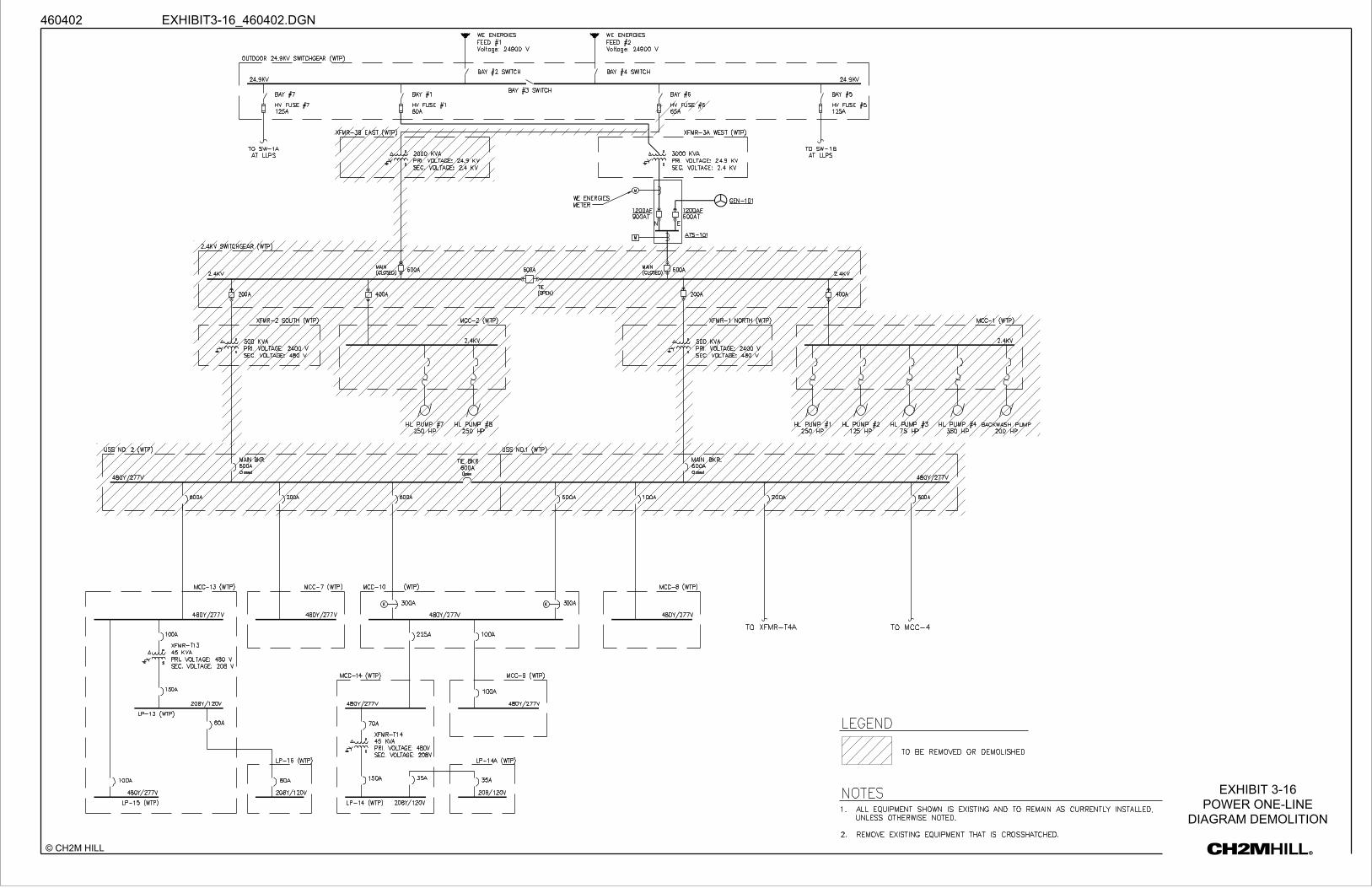
© CH2M HILL
460402
S
P
200A
XFMR-1 NORTH (WTP)
USS NO. 2 (WTP) USS NO.1 (WTP)
Open
500 KVA
PRI. VOLTAGE: 2400 V
SEC. VOLTAGE: 480 VS
P
XFMR-2 SOUTH (WTP)
500 KVA
PRI. VOLTAGE: 2400 V
SEC. VOLTAGE: 480 V
600A
MCC-8 (WTP)
100A600A
300A
TIE BKR
600A
600A
300A
MCC-10 (WTP)
100A
MCC-9 (WTP)
100A
200A
MCC-7 (WTP)
600A
2.4KV SWITCHGEAR (WTP)
200A400A200A
2.4KV
600A
MAIN BKR.
Closed
600A
MAIN BKR.
Closed
KK
480Y/277V
480Y/277V480Y/277V 480Y/277V
480Y/277V 480Y/277V
2.4KV
MAIN
(CLOSED)
MAIN
(CLOSED)
MCC-2 (WTP)
2.4KV
HL PUMP #7
250 HP
HL PUMP #8
250 HP
MCC-1 (WTP)
2.4KV
HL PUMP #1
250 HP
HL PUMP #2
125 HP
HL PUMP #3
75 HP
HL PUMP #4
350 HP
BACKWASH PUMP
200 HP
Voltage: 24900 V
FEED #1
WE ENERGIES
Voltage: 24900 V
FEED #2
WE ENERGIES
OUTDOOR 24.9KV SWITCHGEAR (WTP)
24.9KV
BAY #7
HV FUSE #7
125A
BAY #1
HV FUSE #1
BAY #6 BAY #5
HV FUSE #5
125A
BAY #2 SWITCH BAY #4 SWITCH
BAY #3 SWITCH
24.9KV
MCC-13 (WTP)
480Y/277V
S
P45 KVA
PRI. VOLTAGE: 480 V
SEC. VOLTAGE: 208 V
150A
XFMR-T13
LP-16 (WTP)
208Y/120V
100A
480Y/277V
LP-15 (WTP)
208Y/120V
LP-13 (WTP)
60A
60A
225A100A
480Y/277V
S
P45 KVA
PRI. VOLTAGE: 480V
SEC. VOLTAGE: 208V
150A
XFMR-T14
LP-14A (WTP)
208/120V
LP-14 (WTP)
70A
MCC-14 (WTP)
208Y/120V
S
P
XFMR-3B EAST (WTP)
2000 KVA
PRI. VOLTAGE: 24.9 KV
SEC. VOLTAGE: 2.4 KVS
P
XFMR-3A WEST (WTP)
3000 KVA
PRI. VOLTAGE: 24.9 KV
SEC. VOLTAGE: 2.4 KV
TO SW-1A
AT LLPS
TO SW-1B
AT LLPS
EN
ATS-101
35A 35A
400A
M
METER
WE ENERGIES
1200AF
TIE
(OPEN)
NOTES
GEN-101
TO XFMR-T4A TO MCC-4
600A 600A 600A
600AT
1200AF
900AT
80A
M
HV FUSE #6
65A
REMOVE EXISTING EQUIPMENT THAT IS CROSSHATCHED.2.
UNLESS OTHERWISE NOTED.
ALL EQUIPMENT SHOWN IS EXISTING AND TO REMAIN AS CURRENTLY INSTALLED, 1.
LEGEND
TO BE REMOVED OR DEMOLISHED
EXHIBIT 3-16
POWER ONE-LINE
DIAGRAM DEMOLITION
EXHIBIT3-16_460402.DGN
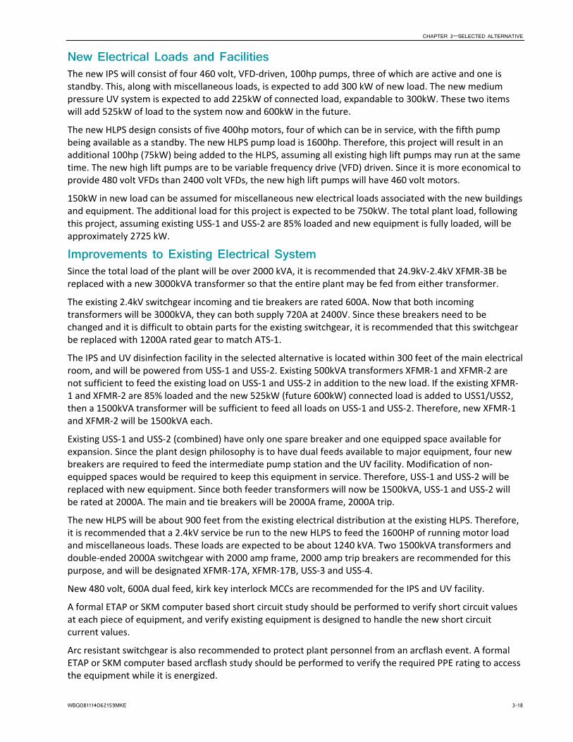
CHAPTER 3—SELECTED ALTERNATIVE
WBG081114062159MKE 3-18
New Electrical Loads and Facilities The new IPS will consist of four 460 volt, VFD‐driven, 100hp pumps, three of which are active and one is standby. This, along with miscellaneous loads, is expected to add 300 kW of new load. The new medium pressure UV system is expected to add 225kW of connected load, expandable to 300kW. These two items will add 525kW of load to the system now and 600kW in the future.
The new HLPS design consists of five 400hp motors, four of which can be in service, with the fifth pump being available as a standby. The new HLPS pump load is 1600hp. Therefore, this project will result in an additional 100hp (75kW) being added to the HLPS, assuming all existing high lift pumps may run at the same time. The new high lift pumps are to be variable frequency drive (VFD) driven. Since it is more economical to provide 480 volt VFDs than 2400 volt VFDs, the new high lift pumps will have 460 volt motors.
150kW in new load can be assumed for miscellaneous new electrical loads associated with the new buildings and equipment. The additional load for this project is expected to be 750kW. The total plant load, following this project, assuming existing USS‐1 and USS‐2 are 85% loaded and new equipment is fully loaded, will be approximately 2725 kW.
Improvements to Existing Electrical System Since the total load of the plant will be over 2000 kVA, it is recommended that 24.9kV‐2.4kV XFMR‐3B be replaced with a new 3000kVA transformer so that the entire plant may be fed from either transformer.
The existing 2.4kV switchgear incoming and tie breakers are rated 600A. Now that both incoming transformers will be 3000kVA, they can both supply 720A at 2400V. Since these breakers need to be changed and it is difficult to obtain parts for the existing switchgear, it is recommended that this switchgear be replaced with 1200A rated gear to match ATS‐1.
The IPS and UV disinfection facility in the selected alternative is located within 300 feet of the main electrical room, and will be powered from USS‐1 and USS‐2. Existing 500kVA transformers XFMR‐1 and XFMR‐2 are not sufficient to feed the existing load on USS‐1 and USS‐2 in addition to the new load. If the existing XFMR‐1 and XFMR‐2 are 85% loaded and the new 525kW (future 600kW) connected load is added to USS1/USS2, then a 1500kVA transformer will be sufficient to feed all loads on USS‐1 and USS‐2. Therefore, new XFMR‐1 and XFMR‐2 will be 1500kVA each.
Existing USS‐1 and USS‐2 (combined) have only one spare breaker and one equipped space available for expansion. Since the plant design philosophy is to have dual feeds available to major equipment, four new breakers are required to feed the intermediate pump station and the UV facility. Modification of non‐equipped spaces would be required to keep this equipment in service. Therefore, USS‐1 and USS‐2 will be replaced with new equipment. Since both feeder transformers will now be 1500kVA, USS‐1 and USS‐2 will be rated at 2000A. The main and tie breakers will be 2000A frame, 2000A trip.
The new HLPS will be about 900 feet from the existing electrical distribution at the existing HLPS. Therefore, it is recommended that a 2.4kV service be run to the new HLPS to feed the 1600HP of running motor load and miscellaneous loads. These loads are expected to be about 1240 kVA. Two 1500kVA transformers and double‐ended 2000A switchgear with 2000 amp frame, 2000 amp trip breakers are recommended for this purpose, and will be designated XFMR‐17A, XFMR‐17B, USS‐3 and USS‐4.
New 480 volt, 600A dual feed, kirk key interlock MCCs are recommended for the IPS and UV facility.
A formal ETAP or SKM computer based short circuit study should be performed to verify short circuit values at each piece of equipment, and verify existing equipment is designed to handle the new short circuit current values.
Arc resistant switchgear is also recommended to protect plant personnel from an arcflash event. A formal ETAP or SKM computer based arcflash study should be performed to verify the required PPE rating to access the equipment while it is energized.

CHAPTER 3—SELECTED ALTERNATIVE
WBG081114062159MKE 3-19
Although this plant will not have any additional 2.4kV loads, the 2.4 kV distribution will remain intact. The recently purchased GEN‐101 and XFMR‐3A are rated for 2.4kV. If 2.4kV distribution were eliminated, these items would be obsolete. 1200A, 2.4kV transfer switches would need to be replaced with large, costly transfer switches rated 4000 amps or larger, and copper costs to deliver 1600‐2000A over the 900 feet to the HLPS would be high.
Existing 480 volt motor control centers are not discussed and will not be replaced as a part of this project. If a system study indicates that an existing piece of equipment no longer meets short circuit requirements, those pieces of equipment will be discussed on a case‐by‐case basis.
Reference Exhibit 3‐17, Power One‐Line Diagram, to see single line diagram of proposed electrical system improvements.

© CH2M HILL
460402
S
P
200A
XFMR-1 NORTH (WTP)
USS NO. 2 (WTP)
Open
1500 KVA
PRI. VOLTAGE: 2400 V
SEC. VOLTAGE: 480 V
S
P
XFMR-2 SOUTH (WTP)
1500 KVA
PRI. VOLTAGE: 2400 V
SEC. VOLTAGE: 480 V
600A
MCC-8 (WTP)
100A600A
300A
TIE BKR
600A
300A
MCC-10 (WTP)
100A
MCC-9 (WTP)
100A
200A
MCC-7 (WTP)
600A
2.4KV SWITCHGEAR (WTP)
400A400A400A
MAIN BKR.
Closed
MAIN BKR.
KK
480Y/277V
480Y/277V480Y/277V 480Y/277V
2.4KV
MAIN
(CLOSED)
MAIN
(CLOSED)
HL PUMP #5
HL PUMP #4
400 HP
HL PUMP #3
400 HPHL PUMP #2
400 HP
HL PUMP #1
400 HP
Voltage: 24900 V
FEED #1
WE ENERGIES
Voltage: 24900 V
FEED #2
WE ENERGIES
OUTDOOR 24.9KV SWITCHGEAR (WTP)
24.9KV
BAY #7
HV FUSE #7
125A
BAY #1
HV FUSE #1
BAY #6 BAY #5
HV FUSE #5
125A
BAY #2 SWITCH BAY #4 SWITCH
BAY #3 SWITCH
24.9KV
MCC-13 (WTP)
480Y/277V
S
P45 KVA
PRI. VOLTAGE: 480 V
SEC. VOLTAGE: 208 V
150A
XFMR-T13
LP-16 (WTP)
208Y/120V
100A
480Y/277V
LP-15 (WTP)
208Y/120V
LP-13 (WTP)
60A
60A
225A100A
480Y/277V
S
P45 KVA
PRI. VOLTAGE: 480V
SEC. VOLTAGE: 208V
150A
XFMR-T14
LP-14A (WTP)
208/120V
LP-14 (WTP)
70A
MCC-14 (WTP)
208Y/120V
S
P
XFMR-3B EAST (WTP)
3000 KVA
PRI. VOLTAGE: 24.9 KV
SEC. VOLTAGE: 2.4 KVS
P3000 KVA
PRI. VOLTAGE: 24.9 KV
SEC. VOLTAGE: 2.4 KV
TO SW-1A
AT LLPS
TO SW-1B
AT LLPS
EN
ATS-101
400 HP
35A 35A
400A
M
METER
WE ENERGIES
1200AF
EN
1,040 KW
GENSET
M
TIE
(OPEN)
NOTES
GEN-101
600AT
1200AF
900AT
80A
M
HV FUSE #6
80A
900AT
1200AF
900AT
1200AF
2.4KV, 1200A 900AT
1200AF
1600AT
2000AF
1600AT
2000AF
1600AT
2000AF
XFMR FOR
MISC LOADS
XFMR-T4A
TO
K
PUMP STATION
INTERMEDIATE
K
480V, 600A
DISINFECTION
UVMISC LOADS
MISC LOADS
K
MCC-4
TO
480V, 600A
K
GENSET
1,026 KWNEW EQUIPMENT
GEN-102
METER
WE ENERGIES
1200AF
600AT
1200AF
900AT
ATS-102
NEW EQUIPMENT
INSTALL NEW AT HIGH LEVEL PUMP STATION.2.
UNLESS OTHERWISE NOTED.
ALL EQUIPMENT SHOWN IS EXISTING AND TO REMAIN AS CURRENTLY INSTALLED, 1.
480V, 2000A
400AT
600AF
400AT
600AF
400AT
600AF
400AT
600AF
400AF
600AT
150A 150A 150A 150A 70A
MCC
VFDVFD VFD VFD
208/120V
480V-
45KVA
400AT
600AF
400AT
600AF
MCC
70A300AT
600AF
208/120V
480V-
45KVA
FUTURE)
(300KW
225KW
400AT
600AF
480V, 2000A
STANDBY
SEE NOTE 2
WEST (WTP)
XFMR-3A
100 HP EACH, 3 ACTIVE, 1 STANDBY
INTERMEDIATE LIFT PUMPS
SPARE
400A
SPARE
400A
480V, 2000A
USS NO. 3 (HLPS)
70A
480V-208/120V
45KVA,
DISINFECTION
UV
SPARE
600A600A600A
VFDVFD
USS NO. 4 (HLPS)
600A 600A 600A
VFD VFD VFD
USS NO. 1 (WTP)
MAIN BKR.
1600AT
2000AF
TIE BKR
1600AT
2000AF
Open
MAIN BKR.
1600AT
2000AF
S
P
1500 KVA
PRI. VOLTAGE: 2400 V
SEC. VOLTAGE: 480 V
XFMR-17A (HLPS)
S
P
1500 KVA
PRI. VOLTAGE: 2400 V
SEC. VOLTAGE: 480 V
XFMR-17B (HLPS)
EXHIBIT 3-17
POWER ONE-LINE
DIAGRAM
EXHIBIT3-17_460402.DGN

CHAPTER 3—SELECTED ALTERNATIVE
WBG081114062159MKE 3-21
Future Expansion Capabilities This study considered provisions for future expansion of the electrical system.
The 2.4kV switchgear load is expected to be at just over 600 amperes. The new switchgear will be specified with a rating of 1200A. The load on this switchgear can be nearly doubled. Two spare 400A breakers and two equipped spaces will be added to this equipment for future expansion.
24.9kV‐2.4kV transformers XFMR‐3A and XFMR‐3B may be upgraded from 3,000 kVA transformers to 5,000 kVA transformers, and the 2.4kV switchgear will not need to be replaced.
2.4kV‐480V transformers XFMR‐1 and XFMR‐2 are recommended to be 1500 kVA. These transformers are sized to accommodate additional 480 volt systems. Approximately 675kW of 480 volt loads are being added to the plant, while each transformer will be increased in size by 1000 kVA.
480V switchgear USS‐1 and USS‐2 are also being upgraded from 600A to 2000A. Approximately 800A of new loads would be added as a part of this project. Therefore, this gear could accommodate an additional 600A of load.
USS‐3 and USS‐4 will be rated at 2000A. The fifth high lift pump could run if needed.
Final design should consider the expansion capabilities of this equipment, as several options are available to accommodate additional loads in the future.
Backup Generator Considerations When GEN‐101 was installed in 2011, it was intended to provide backup power for some but not all existing loads. GEN‐101 is capable of running up to 1000kVA of existing loads powered from USS‐1 and USS‐2, since the generator is capable of providing 1282 kVA. GEN‐101 can run some but not all high lift pumps.
The new IPS and UV facility will require generator power. The HLPS loads are also increasing, and will require additional backup power.
Since approximately 750kW will be added to the plant load as a part of this plant expansion, it is recommended that a new 2.4kV, 1040 kW GEN‐102 be added, along with a new 1200A ATS‐102 so that the additional backup power may be brought on line.
The existing GEN‐101 and new GEN‐102 will be provided with the appropriate synchronization software so that the 2000+ kW available may be available to both sides of the 2.4kV tie breaker.
GEN‐102 and ATS‐102 could be located in the existing HLPS near the 2.4kV switchgear, GEN‐101 and ATS‐101. This will reduce the cost of copper and be more convenient for plant operators to access both generators and transfer switches.
Since GEN‐101 and GEN‐102 each feed a 1200A ATS, the generator sizes may be increased in the future to accommodate expansion.
Summary of Electrical Improvements The electrical improvements described above will accomplish the following:
Replace 40 year old power distribution equipment for which it is difficult to find parts. The new equipment will double the power distribution capability of the water treatment plant. The existing 2.4kV switchgear, 2.4kV‐480V transformers, and existing 480 volt switchgear will be replaced with new, larger capacity equipment for loads associated with this project and also to accommodate future expansion.
Provide a power distribution system in the new HLPS. The new HLPS will require two 2.4kV‐480V transformers (XFMR‐17A, XFMR‐17B) and 480V switchgear (USS‐3, USS‐4) for power distribution. Five VFDs will be provided to drive the new high lift pumps. The VFDs will allow the plant operators to control motor speed.
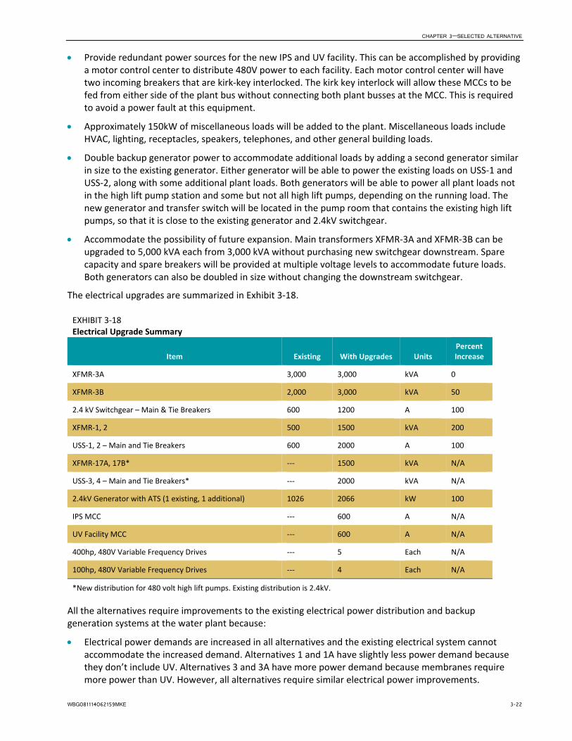
CHAPTER 3—SELECTED ALTERNATIVE
WBG081114062159MKE 3-22
Provide redundant power sources for the new IPS and UV facility. This can be accomplished by providing a motor control center to distribute 480V power to each facility. Each motor control center will have two incoming breakers that are kirk‐key interlocked. The kirk key interlock will allow these MCCs to be fed from either side of the plant bus without connecting both plant busses at the MCC. This is required to avoid a power fault at this equipment.
Approximately 150kW of miscellaneous loads will be added to the plant. Miscellaneous loads include HVAC, lighting, receptacles, speakers, telephones, and other general building loads.
Double backup generator power to accommodate additional loads by adding a second generator similar in size to the existing generator. Either generator will be able to power the existing loads on USS‐1 and USS‐2, along with some additional plant loads. Both generators will be able to power all plant loads not in the high lift pump station and some but not all high lift pumps, depending on the running load. The new generator and transfer switch will be located in the pump room that contains the existing high lift pumps, so that it is close to the existing generator and 2.4kV switchgear.
Accommodate the possibility of future expansion. Main transformers XFMR‐3A and XFMR‐3B can be upgraded to 5,000 kVA each from 3,000 kVA without purchasing new switchgear downstream. Spare capacity and spare breakers will be provided at multiple voltage levels to accommodate future loads. Both generators can also be doubled in size without changing the downstream switchgear.
The electrical upgrades are summarized in Exhibit 3‐18.
EXHIBIT 3‐18 Electrical Upgrade Summary
Item Existing With Upgrades Units Percent Increase
XFMR‐3A 3,000 3,000 kVA 0
XFMR‐3B 2,000 3,000 kVA 50
2.4 kV Switchgear – Main & Tie Breakers 600 1200 A 100
XFMR‐1, 2 500 1500 kVA 200
USS‐1, 2 – Main and Tie Breakers 600 2000 A 100
XFMR‐17A, 17B* ‐‐‐ 1500 kVA N/A
USS‐3, 4 – Main and Tie Breakers* ‐‐‐ 2000 kVA N/A
2.4kV Generator with ATS (1 existing, 1 additional) 1026 2066 kW 100
IPS MCC ‐‐‐ 600 A N/A
UV Facility MCC ‐‐‐ 600 A N/A
400hp, 480V Variable Frequency Drives ‐‐‐ 5 Each N/A
100hp, 480V Variable Frequency Drives ‐‐‐ 4 Each N/A
*New distribution for 480 volt high lift pumps. Existing distribution is 2.4kV.
All the alternatives require improvements to the existing electrical power distribution and backup generation systems at the water plant because:
Electrical power demands are increased in all alternatives and the existing electrical system cannot accommodate the increased demand. Alternatives 1 and 1A have slightly less power demand because they don’t include UV. Alternatives 3 and 3A have more power demand because membranes require more power than UV. However, all alternatives require similar electrical power improvements.

CHAPTER 3—SELECTED ALTERNATIVE
WBG081114062159MKE 3-23
Some electrical equipment is 40 years old and beyond its intended life.
Additional backup electrical generation capacity is needed. The existing backup generator does not accommodate all the existing electrical loads, and an additional generator was planned to handle new loads.
A summary of the electrical improvements include:
Replace 40 year old power distribution equipment which is beyond its intended life and difficult to find parts for.
Provide a new power distribution system in the new HLPS.
Provide redundant power sources for the new IPS and UV facility.
Increase backup electrical generator power to accommodate additional loads and increase reliability.
These improvements are estimated to add another $2 to $3 million in capital cost to the project. The electrical improvements greatly improve reliability, longevity and flexibility for future expansion.