engineering standards for public works in conjunction with
TRANSCRIPT

ENGINEERING STANDARDS
For Public Works in Conjunction with the
Development of Subdivisions, Commercial & Industrial Property
City of Rochester Public Works Department

TABLE OF CONTENTS
TABLE OF CONTENTS 03/23/2018
SECTION 1001 SCOPE ................................................................................................... 1
1001.1 DESCRIPTION ...................................................................................................................................... 1 1001.2 ENGINEERING REQUIREMENT ........................................................................................................... 1 1001.3 DEFINITION OF TERMS ....................................................................................................................... 1 1001.4 REFERENCE DOCUMENTATION .......................................................................................................... 2
SECTION 1002 ROADWAY DESIGN ........................................................................... 4
1002.1 RIGHT-OF-WAY & STREET WIDTHS ................................................................................................. 4 1002.2 COMPLETE STREETS .......................................................................................................................... 4 1002.3 TYPICAL CROSS-SECTION .................................................................................................................. 4 1002.4 CURBING ............................................................................................................................................. 4 1002.5 VERTICAL AND LONGITUDINAL CONTROLS ...................................................................................... 4 1002.6 GEOTECHNICAL REPORT ................................................................................................................... 5 1002.7 PAVEMENT DESIGN ............................................................................................................................ 6 1002.8 FUTURE SIDE STREETS ....................................................................................................................... 7 1002.9 TEMPORARY STREET ENDS ................................................................................................................ 7 1002.10 TEMPORARY SECONDARY ACCESS .................................................................................................. 7 1002.11 LOCATION OF UTILITIES .................................................................................................................. 7 1002.12 UTILITY CONDUIT CROSSINGS ......................................................................................................... 8 1002.13 UTILITY EASEMENTS ........................................................................................................................ 8 1002.14 PEDESTRIAN FACILITIES .................................................................................................................. 8
SECTION 1003 SANITARY SEWER DESIGN .......................................................... 10
1003.1 SIZING SANITARY SEWERS ............................................................................................................... 10 1003.2 PIPE MATERIAL ................................................................................................................................ 10 1003.3 MANHOLE STRUCTURES ................................................................................................................... 10 1003.4 SPACING AND ALIGNMENT ............................................................................................................... 10
SECTION 1004 WATERMAIN DESIGN .................................................................... 12
1004.1 SIZING WATERMAINS ....................................................................................................................... 12 1004.2 PIPE MATERIAL ................................................................................................................................ 12 1004.3 SPACING AND ALIGNMENT ............................................................................................................... 12
SECTION 1005 STORM SEWER DESIGN ................................................................ 15
1005.1 DRAINAGE PLAN ............................................................................................................................... 15 1005.2 SIZING STORM SEWER...................................................................................................................... 15 1005.3 PIPE MATERIAL ................................................................................................................................ 15 1005.4 MANHOLE AND CATCH BASIN STRUCTURES ................................................................................... 16 1005.5 INLET APRONS .................................................................................................................................. 16 1005.6 OUTLET STRUCTURES ...................................................................................................................... 16 1005.7 SPACING AND ALIGNMENT ............................................................................................................... 16 1005.8 SIZING DRAINAGE WAY, OPEN CHANNELS ..................................................................................... 17 1005.9 STORM WATER TREATMENT PONDS ............................................................................................... 17 1005.10 GRADING PLAN CHECKLIST ........................................................................................................... 18 1005.11 SUBDRAINS ...................................................................................................................................... 18 1005.12 FUTURE STORM LATERALS, STUBS ................................................................................................ 18
SECTION 1006 SERVICE CONNECTIONS .............................................................. 20
1006.1 SIZING SERVICE CONNECTIONS ....................................................................................................... 20 1006.2 PIPE MATERIAL ................................................................................................................................ 20
SECTION 1007 PUMPING STATION ........................................................................ 21
1007.1 LIFT STATION DESIGN ...................................................................................................................... 21 1007.2 FORCEMAIN DESIGN ......................................................................................................................... 21 1007.3 COATINGS AND MATERIALS ............................................................................................................. 21
TABLE OF CONTENTS
TABLE OF CONTENTS 03/23/2018
1007.4 SITE LAYOUT .................................................................................................................................... 22 1007.5 POWER .............................................................................................................................................. 22 1007.6 INSTRUMENTATION .......................................................................................................................... 22
SECTION 1008 EROSION AND SEDIMENT CONTROL ....................................... 24
1008.1 REQUIRED DOCUMENTATION .......................................................................................................... 24 1008.2 CONSTRUCTION REQUIREMENTS .................................................................................................... 24 1008.3 TEMPORARY EROSION AND SEDIMENT CONTROL .......................................................................... 24 1008.4 PERMANENT EROSION AND SEDIMENT CONTROL .......................................................................... 25
SECTION 1009 DECORAH EDGE AREAS ............................................................... 26
1009.1 GENERAL .......................................................................................................................................... 26 1009.2 ROADWAY PLANS ............................................................................................................................. 26 1009.3 UNDERGROUND UTILITIES ............................................................................................................... 26
SECTION 1010 TREE PLANTING, PRESERVATION, AND PROTECTION ..... 27
1010.1 DESCRIPTION .................................................................................................................................... 27 1010.2 DEFINITION OF TERMS ..................................................................................................................... 27 1010.3 ENGINEERING REQUIREMENT ......................................................................................................... 27 1010.4 CONSTRUCTION REQUIREMENT ...................................................................................................... 27
SECTION 1011 PROJECT DEVELOPMENT............................................................ 29
1011.1 GENERAL .......................................................................................................................................... 29 1011.2 PREDESIGN MEETING ....................................................................................................................... 29 1011.3 PRE-GRADING PLAN PREPARATION MEETING ................................................................................. 30 1011.4 GRADING PLAN PRE-SUBMITTAL MEETING ..................................................................................... 30
SECTION 1012 STANDARD PLANS .......................................................................... 31
1012.1 GENERAL .......................................................................................................................................... 31 1012.2 MODIFICATIONS TO THE MN/DOT SAMPLE PLAN ......................................................................... 31
SECTION 1013 SUBMISSION OF PLANS ................................................................. 33
1013.1 PLANS AND SPECIFICATIONS ........................................................................................................... 33 1013.2 ESTIMATES ....................................................................................................................................... 33 1013.3 CITY-OWNER CONTRACTS .............................................................................................................. 33 1013.4 ELECTRONIC DRAWINGS ................................................................................................................. 33 1013.5 RECORD DRAWINGS ......................................................................................................................... 34
SECTION 1014 CONSTRUCTION SUPERVISION ................................................. 35
1014.1 PRE-CONSTRUCTION CONFERENCE ................................................................................................ 35 1014.2 CONSTRUCTION PROGRESS MEETINGS ........................................................................................... 36 1014.3 NOTICE TO PROCEED ....................................................................................................................... 37 1014.4 SURVEYING ....................................................................................................................................... 37 1014.5 INSPECTION ...................................................................................................................................... 37 1014.6 UTILITY TESTING ............................................................................................................................. 39 1014.7 DETAILED STAGE INSPECTIONS ...................................................................................................... 39 1014.8 PAVEMENT QUALITY ASSURANCE USING CORES ........................................................................... 40 1014.9 ACCEPTANCE .................................................................................................................................... 40
SECTION 1015 SCHEDULE OF MATERIALS CONTROL ................................... 41
1015.1 GENERAL .......................................................................................................................................... 41

ENGINEERING STANDARDS PAGE 1 03/23/2018
Section 1001 SCOPE
1001.1 Description
In order to standardize engineering requirements for Developers and Engineers performing work within the City of Rochester, it is important that certain guidelines be followed.
These guidelines outline certain requirements, materials, and standards that shall be incorporated into the preparation of plans and specifications for sanitary sewer, storm sewer, storm water treatment ponds, watermains, service connections, pedestrian facilities, street construction, and associated erosion control within the Rochester Urban Service Area, unless otherwise authorized by the City Engineer.
Compliance with these guidelines will help provide quality projects and assure uniform performance standards for the citizens of Rochester.
1001.2 Engineering Requirement
As set forth in various sections of City ordinances, developers of property within the City are required to submit certain professionally prepared and signed plans and specifications for review and approval by the City. These include such items as grading plans, drainage reports, topographic surveys and plats, street and utility plans and specifications.
All plans and specifications for construction of public works shall be prepared by or under the direction of a Professional Engineer (herein after “Engineer”) licensed under the laws of the State of Minnesota.
The Engineer shall be responsible for the accuracy and completeness of the plans and specifications and the thoroughness and quality of the field inspections. The Engineer shall annotate on the review set and as builts that all location and elevations of storm and sanitary have been verified. The Engineer shall be familiar with all of the reference documents listed herein.
The City Engineer will review the plans for general compliance with department practice. Approval of the plans and specifications by the City does not relieve the Engineer of full responsibility for the adequacy of design or accuracy of computations and details.
Engineering services include; preparation of plans and specifications, field staking and resident inspection in order to assure the City that the completed project is in conformance with the approved plans and specifications, and submission of record drawings.
1001.3 Definition of Terms
A. Public Works
Public Works as used herein are defined as those facilities for transportation, conveyance of sanitary and storm flows and potable water that are constructed within the public right-of-way or on public easements for the use of the general public. The Public Works Department is that department of the City of Rochester responsible for the management and oversight of Public Works facilities.
B. “ROCOG”
Rochester-Olmsted Council Of Governments, 2122 Campus Drive SE
C. Engineer
ENGINEERING STANDARDS PAGE 2 03/23/2018
Engineer as used herein is defined as Professional Engineer licensed under the laws of the State of Minnesota.
D. City Engineer
City Engineer as used herein is defined as the Rochester City Engineer or his / her designee, the Manager of Engineering.
E. Developer
Developer as used herein is defined as a person, company, corporation, or limited partnership that develops property within the City of Rochester that is served by Public Works facilities.
F. Contractor
Contractor as used herein is defined as company that performs construction activities for the public infrastructure facilities.
1001.4 Reference Documentation
The following reference documentation shall be the latest edition, including amendments and published updates.
1. Minnesota Department of Transportation (Mn/DOT) (a) Standard Specifications for Construction (b) Standard Detail Plates
2. Great Lakes-Upper Mississippi River Board of State and Provincial Health and Environmental Managers
(a) Recommended Standards for Wastewater Facilities (b) Recommended Standards for Water Works
3. Minnesota Department of Health; (a) Chapter 4715 Plumbing Code (b) Chapter 4720 Public Water Supplies (c) Chapter 4715 Wells & Borings (d) Chapter 4715 Explores & Exploratory Borings
4. City of Rochester (a) Standard Specifications for Street and Utility Construction (b) Standard Detail Plates (c) Checklist for:
Subdivision and Non-Residential Lot Grading Plans
Single Residential Lot Grading Plans
Permanent Storm Water Management Plans and Pond Acceptability
City Owner Contract Program Documentation
Construction Plan Review
(d) Building and Fire Prevention Code (e) Ordinances (f) Land Development Manual
5. Rochester Public Utilities Water Service Rules and Regulations
ENGINEERING STANDARDS PAGE 3 03/23/2018
6. ROCOG Long-Range Transportation Plan

ENGINEERING STANDARDS PAGE 4 03/23/2018
Section 1002 ROADWAY DESIGN
1002.1 Right-of-Way & Street Widths
For classification of streets and resulting minimum widths refer to the ROCOG Long-Range Transportation Plan for “Local Street Right-of-Way and Minimum Roadway Width Requirements” available at http://www.co.olmsted.mn.us.
The City of Rochester Standard Detail Plate shows typical cross-section information. Private streets must conform to the same City of Rochester design standards as Public streets.
On cul-de-sacs (without parking) the minimum radius to back of curb shall be 40.5 feet.
1002.2 Complete Streets
The City of Rochester Department of Public Works “Complete Streets Policy”, adopted by City Council, are incorporated herein by reference.
1002.3 Typical Cross-Section
Cross-slope – desired 2% on driving lanes (maximum with variance request 3%), 2% to 5% on parking lanes, and 3% to 5% on boulevards.
A 2’ clear zone area shall be provided from the face of curb to the face of any obstruction.
Sidewalk location – 1.0’ from property line for sidewalk widths of greater than or equal to 5 feet, 0.5’ from property line for sidewalk widths less than 5 feet.
1002.4 Curbing
All streets and alleys shall be constructed with concrete curb and gutter on both sides. Concrete alleys may be designed with an inverted crown in lieu of the curb and gutter.
Curb and gutter shall be design B-624 in all commercial/industrial streets, all multi-family residential (more than 2 families per dwelling unit), all streets centerline grade of 8% or steeper, all intersection radii, at drainage structures, and on residential streets that are platted as ‘Controlled Access’ (or similar restriction).
Minimum longitudinal slope on curbing is 0.4%. Minimum longitudinal slope on curbing for streets leading to a cul-de-sac is 0.5%. The minimum longitudinal slope on curbing for the radial portion of a cul-de-sac is 1%.
4" drive over concrete curb and gutter will be permitted at one and two family residential areas where driveway locations have not been established and street grades are less than 8%.
Pedestrian ramps, conforming to current ADA requirements, shall be placed at all intersection corners.
Where sidewalk abuts curb, the curb shall be modified to include a sill on the back on which the walk will rest.
Expansion joints shall be placed at the ends of all curved sections, at the ends of the curved portions of street returns, at drainage structures and where abutting other concrete. The spacing of joints shall not exceed 300 feet.
1002.5 Vertical and Longitudinal Controls
ENGINEERING STANDARDS PAGE 5 03/23/2018
Reference – Roadway and Subdivision Design Standards in the City of Rochester Zoning Ordinance 64.200.
2% maximum longitudinal grade through intersections to within 25’ of assumed stop condition or the right of way line extended whichever is greater. Intersection cross-slope crown rollover shall be 3% maximum.
1002.6 Geotechnical Report
City Owner contracts, shall include a Geotechnical Report prepared and signed by a geotechnical professional. On City led projects, a condensed version may be accepted at the discretion of the Engineer.
The report must contain the following
1. The purpose and goals of the report. 2. The methodology used of field investigation/observation and laboratory analysis. 3. Description of soils and geological setting. 4. Maps showing field observation locations and finding. 5. Soil boring log and test pit profiles. 6. Ground water presence and indication of past ground water. 7. Laboratory test results and conclusions. 8. Special/unique observations. 9. Descriptions of rock locations and characteristics. 10. Descriptions of unsuitable soil locations and characteristics. 11. Descriptions of manmade features/pavements, locations and characteristics. 12. Data shall be provided using the city soil boing collection template.
Geotechnical Report must contain the following conclusions and recommendations as appropriate for the project:
1. Material management (a) Topsoil thickness and appropriate ultimate placement. (b) Soils that are not suitable for placement in street and disposition of those materials. (c) Shot rock maximum size to be suitable for placement in street and disposition of
oversized rocks. (d) Existing pavement rubble and rubble from manmade structures
1. Soil placement recommendations related to structures. 2. Utility installation geotechnical recommendations. 3. Fill and backfill recommendations. 4. Soil placement/compaction/maximum moisture recommendations. 5. Slope stability recommendations. 6. Recommendations related to retaining walls and other special structures. 7. Trench sloping recommendations 8. Drainage and subdrain recommendations. Detailed justification must be included for any project requesting waiver of subdrain requirement along both curbs. 9. Likelihood of Karst or similar conditions and recommended actions should conditions be

ENGINEERING STANDARDS PAGE 6 03/23/2018
found. 10. Materials testing, proof roll, etc. recommendation greater than those required for normal projects. 11. Pavement Design soil factor (R-value) and explanation for recommendation. 12. Other recommendations
The report may include the following
1. Pavement Design Report, as a separate section. 2. Conclusions and recommendations related to the installation of public utilities and other infrastructure. 3. Information related to the mass grading of the site, for the preparation of building pads and footings and foundations, and for the placement and compaction of private streets and parking lots.
1002.7 Pavement Design
All rigid and flexible pavements shall be designed in accordance with the procedures set forth in the Pavement Manual of the Minnesota Department of Transportation.
City Owner contracts, that include street pavements, shall include a Pavement Design Report prepared and signed by a licensed professional engineer. The report shall utilize the conclusions and recommendations of the Geotechnical Report.
The report must contain the following
1. The purpose and goals of the report. 2. The Mn/DOT methodology used for the analysis 3. Soils factor or R-value used. Recommended measures shall be provided for special conditions such as excess moisture or highly expansive soils 4. Equivalent Single Axle Load Traffic Forecasting with volume and vehicle type distribution (6% trucks minimum) used for the recommendations. Indicate the source of the projections. 5. Consideration of pavement materials concrete and bit options 6. 50-year pavement life, including maintenance preservation schedule for overlay, seal coat, or rehabilitation. 7. Summary of calculations containing layer thickness of pavement, aggregate base and granular subbase or geotextile fabric.
Unless otherwise directed by the City Engineer the minimum structural sections are as follows:
Flexible pavements include 4" bituminous surfacing and 8” Aggregate Base.
Rigid pavements include 7" concrete surfacing and 5” Aggregate Base.
Select Granular shall comply with Mn/DOT section 3149.2B Table 3149-1, line 4.
“Breaker Run” shall be defined as a 100% crushed carbonate quarry rock meeting the following gradation requirements:
Sieve Size % Passing 4” 100 1” 35-75 #4 10-40
#200 0-5
ENGINEERING STANDARDS PAGE 7 03/23/2018
1002.8 Future Side Streets
Where accesses to future subdivision of adjacent land are shown on the plans, right-of-ways and all roadway improvements including, pavement, curb and gutter, and utilities on the side street, shall be constructed and extended to the end of the side lot or the boundary of the development whichever is greater. Projected profiles and alignments of the future street shall be shown on the plans.
1002.9 Temporary Street Ends
All temporary street ends shall be closed with temporary barricades (Mn/DOT 8002) and are to be fully reflectorized and properly maintained until the street is extended. Temporary street ends or cul-de-sacs shall include the following items, unless waived by the City Engineer.
1. Minimum temporary surface section shall include 6 inches of Aggregate Base and 3 inches bituminous.
2. Paved surface shall be as shown on the detail plate or the equivalent minimum radius according to the requirements for a cul-de-sac.
3. Erosion and sediment control measures shall be taken to prevent soil erosion. They shall be properly maintained, according to the schedule submitted to and approved by the city, until the permanent street is constructed or another permit holder assumes responsibility.
1002.10 Temporary Secondary Access
Where Temporary Secondary Access to subdivisions are shown on the plans, right-of-ways and all roadway improvements shall include
1. Minimum driving surface width of 20 feet. 2. Minimum design Alignment and Profile of 15 mph. 3. Minimum surface section 8 inches of Aggregate Base. 4. The surface shall be paved within 200 feet of any public roadway. 5. Erosion and sediment control measures shall be taken to prevent soil erosion. They shall
be properly maintained, according to the schedule submitted to and approved by the city, until the permanent street is constructed or another permit holder assumes responsibility.
6. Routine roadway maintenance shall be performed to ensure it remains passable throughout the year, until the permanent street is constructed.
1002.11 Location of Utilities
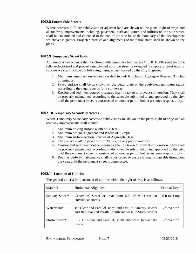
The general criteria for placement of utilities within the right-of-way is as follows:
Material Horizontal Alignment Vertical Depth
Sanitary Sewer* Center of Street or, maximum 5.5’ from center on curvilinear streets
6 ft over top
Watermain* 10' Clear and Parallel, north and east, to Sanitary sewers and 10' Clear and Parallel, south and west, to Storm sewers
7ft over top
Storm Sewer* 5’ - 10' Clear and Parallel, south and west, to Sanitary Sewer.
2ft over top

ENGINEERING STANDARDS PAGE 8 03/23/2018
Subdrain Both sides of street behind curbs 3.5 ft over top
Electric Telephone Cable TV, Gas
Easement adjacent to ROW 3 ft
* Sanitary Sewer, watermains, and storm sewer are generally to be kept within the paved street area. In no case shall the sewer or watermain be placed within 3 feet of the lip of gutter. Public sewer and watermains outside the public right-of-way are to be located in dedicated public easements. Landscaping features should be kept outside utility easement areas in order to facilitate future utility maintenance activity.
Water service lines are not to be connected to the looping portion of watermains located outside public right-of-way.
A plumbing permit is required for any utility manhole structure located within 10 feet of a building.
1002.12 Utility Conduit Crossings
Utility ducts shall be constructed according to the Detail Plates and placed across streets at locations provided by the Rochester Public Utility Electric, Telephone, Gas, and Cable TV companies. The Engineer shall include the ducts on the plans and special provisions. The utility shall make arrangements with the developer to cover the costs of the ductwork.
1002.13 Utility Easements
Where public sanitary sewer, watermain, storm sewer, or subdrain is outside of platted ROW, the horizontal distance from the pipe to the edge of the easement shall be at least 10’ or at least equal to the depth of the pipe, whichever is greater. The minimum easement width shall be 20’.
1002.14 Pedestrian Facilities
A. Sidewalks
All streets shall be finish graded to provide for future boulevard and sidewalk on both sides. Pedestrian curb ramps shall be constructed at all quadrants of intersections. All driveways are constructed with a sidewalk section. Where sidewalks do not allow for sufficient boulevard width to maintain vegetation, boulevards shall be paved with materials approved by the City Engineer.
Widths:
1. 5’ wide on all commercial/industrial streets and all residential streets with a right of way width of more than 56’. 2. 4’ wide on residential streets with a right of way width of 56’ or less and on cul-de-sacs of 20 dwelling unit or less.
B. Bikeways
Bikeways shall conform to the AASHTO “Guide for the Development of Bicycle Facilities”.
Bikeways shall conform to Minnesota Department of Transportation “MnDOT Bikeway Facility Design Manual” and State Aid Standards.

ENGINEERING STANDARDS PAGE 9 03/23/2018
Bikeways are to be 10' wide with 2’ recovery area on both sides, and sloped to drain toward the drainage way or gutter.

ENGINEERING STANDARDS PAGE 10 03/23/2018
Section 1003 Sanitary Sewer Design
1003.1 Sizing Sanitary Sewers
Sizing of sanitary sewers shall be 8" minimum.
All sewers shall be designed to have sufficient slope to provide mean velocities of not less than 2 fps based on Manning’s formula using an N factor of 0.013. Sizing to be reviewed by the City Engineer prior to final plans preparation. Private sanitary sewers must be reviewed by the City of Rochester, Building Safety Department.
The City shall reimburse the Owner/Developer for the incremental cost of the materials to increase the size of the sanitary sewer above an 8” diameter pipe if requested by the City Engineer. The City shall also reimburse the required incremental cost of the increase in the width of the manhole size if it is solely required for the oversize sanitary trunk sewer pipe. The Public Works Department shall establish the reimbursement amount for each item concurrent with the adjustments in the City’s standard rates, which occur August 1st of each year. Invoices for such reimbursements, together with supporting information, are to be submitted to Rochester Public Works for processing, verification and payment. Sanitary sewer mains are to be extended to the end limits of new subdivisions where practical to facilitate future sanitary sewer system extensions.
The Engineer shall verify elevations downstream and upstream prior to any connection and notify the City of any inconsistencies in the system.
1003.2 Pipe Material
Watermain quality pipe shall be used in all common trench installations.
Sanitary sewers passing over or under watermains shall be constructed of materials equal to watermain standards of construction for a distance of nine feet on either side of the watermain.
Sanitary sewers crossing watermains or storm sewers shall be constructed with adequate structural support to prevent excessive deflection of joints, or settling on the watermains or storm sewer.
1003.3 Manhole Structures
Manholes and other special access structures shall be constructed at designated locations as required by the Plans and in accordance with any standard detail drawings or special design requirements given therefor.
Unless otherwise specified or approved, manholes shall be constructed on a precast or cast-in-place concrete base and the barrel riser sections, and cone section shall all be of precast concrete. All units shall be properly fitted and sealed to form a completely watertight structure.
All sanitary structures shall include the design requirements of the waterproofing standard detail.
All structures located as parts of forcemain systems and immediately downstream and other specific areas subject to high concentrations of corrosive materials (i.e. hydrogen sulfide) shall be fully lined with a protective coating, by a Licensed or Certified Contractor performing the special work.
1003.4 Spacing and Alignment
Sanitary sewers shall be placed on tangent alignment with manholes at changes in pipe size, horizontal alignment and/or vertical alignment. Spacing of manholes shall not exceed 400 feet for pipelines 8-15” diameter, 500’ for pipelines 18-30” diameter, and 800’ for pipelines 36-84” (unless approved by the City Engineer).

ENGINEERING STANDARDS PAGE 11 03/23/2018
Outside drop manholes shall be constructed at locations where the difference in inlet and outlet elevations exceeds 1’ (one foot).
Changes in flow direction at manholes shall not exceed 90 degrees.
4” and 6” Service connections to the sewer main shall only be considered at locations in-between two manholes. 8” or larger services should be connected at a manhole. Lamp holes shall not be installed at the end of sanitary sewers.
ENGINEERING STANDARDS PAGE 12 03/23/2018
Section 1004 Watermain Design
1004.1 Sizing Watermains
Standard watermain size for water distribution system design is eight (8) inch diameter.
Looping of watermains is required in all cul-de-sacs and dead end streets unless topographic conditions make it impractical. Watermains are to be extended to the end limits of new subdivisions to facilitate future water system extensions and looping. Six (6) inch diameter watermains may be allowed for short (less than 150 feet long) unavoidable dead-ends or short looped areas if the design will provide minimum required fire flows at minimum allowable pressure.
Twelve (12) inch or larger diameter watermains may be required by the City Engineer based on watermain hydraulic capacity requirements to serve future adjacent portions of the water distribution system. Proposed watermain sizing is to be reviewed with Rochester Public Utilities prior to final plan and specification preparation.
Rochester Public Utilities (RPU) will reimburse the Owner/Developer the incremental cost for constructing over-sized mains, valves and fittings larger than 8” diameter if requested by the City Engineer. The Public Utilities Department (RPU) will annually establish the maximum allowable oversize reimbursement amount for oversize items Invoices for such reimbursements, together with supporting information, are to be submitted to Rochester Public Utilities for processing, verification and payment.
1004.2 Pipe Material
Watermain shall be ductile-iron pipe complying with (W200) “Watermain Specifications", Standard Specifications for Street and Utility Construction, Rochester, Minnesota.
Polyethylene encasement shall be required on all ductile iron pipe.
1004.3 Spacing and Alignment
Watermains designed for connection to the Rochester municipal water system must comply with Minnesota Department of Health (herein after “Health Department”) standards. All such watermain plans and specifications are to be reviewed and approved by the Health Department prior to construction. Review and approval of these plans and specifications by Rochester Public Utilities is also required (before plan submission to the Health Department).
The description of the Minnesota Department of Health watermain, sanitary sewer and storm sewer separation requirements, which follows, is to be considered an aid to watermain designers to explain current requirements. The description is in no way intended to relieve the designer from meeting Health Department separation requirements.
1. Horizontal Alignment: Watermains are generally to be aligned parallel with sanitary sewers with a 10’ minimum edge-to-edge separation from any storm or sanitary gravity sewer or force main. As noted in Section 1002 of these Guidelines, a 3’ minimum edge-to-edge distance is to be maintained from the front lip of the concrete curb and gutter.
(a) Conditions permitting separation exceptions from gravity sewers: (No exceptions allowed from sanitary force mains) 1) Solid rock in trench 2) Narrow street pavement with multiple utilities
(b) Exception Procedure: The Engineer must submit to the Minnesota Department of Health supporting data and a request for the alignment exception along with the required plan and specification submittals and fees.
ENGINEERING STANDARDS PAGE 13 03/23/2018
(c) Exception Details: 1) Water main quality pressure pipe sewer is required and must be pressure tested to
ensure water tightness.
2) Water mains are preferred to be located above the sanitary sewer with a minimum vertical edge-to-edge separation of 18”. Where this is not possible when passing a manhole structure, one full length of water main pipe shall be located so that both joints will be as far as possible away from the manhole structure. No contact with the manhole is allowed.
2. Vertical Alignment: Generally 7’ minimum and 10’ maximum bury from finished grade. A 6’ bury may be allowed in certain unpaved areas such as stream crossings, narrow ditch crossings, etc. Future finished grade lines in unimproved areas must be determined and shown on the construction plans. 3. Sewer Crossings: Water mains crossing sewers shall be kept to a minimum. The crossings shall be aligned to be as nearly perpendicular as possible. Water mains are preferred to be located over the sanitary sewer with a minimum vertical edge-to-edge separation of 18”. One full length of water main pipe shall be located so that both joints of the watermain will be as far as possible away from the storm or sanitary sewer crossing.
(a) Allowed Exceptions From Gravity Sewers: (No Exceptions Allowed From Sanitary Force Mains) Only where deemed impossible to maintain vertical separation and or full pipe length restriction.
(b) Exception Procedure: The Engineer must submit to the Minnesota Department of Health supporting data and a request for the alignment exception along with the required plan and specification submittals and fees.
(c) Exception Details: Water main quality pressure pipe sewer is required and must be pressure tested to ensure water tightness.
4. Surface Water Crossings: Surface Water Crossings: Water mains crossing under surface waters greater than 15' in width must be provided with restrained joints from top of bank to top of bank. The restrained joints are to be called out on the plan sheet, and are to be considered an incidental pay item. Valves shall be located at both sides of the crossing within an accessible area above the water table not subject to flooding. No service connections are allowed between the isolation valves. A fire hydrant shall be located between the isolation valves in an accessible area to allow for pressure testing of the crossing to determine leakage.
Fire Hydrants: The Rochester Fire Prevention Bureau must approve all fire hydrant locations. Fire hydrants must be located at all street intersections, at the sides of all cul-de-sacs, at the end of all temporary or permanent dead-ends that include service connections, at the end of all dead-ends that are longer than 150’ that do not have service connections and at all dead-ends created between water system pressure zones.
In residential areas with usable frontage, fire hydrants shall be spaced a maximum of 400’ apart. Commercial and multi-family areas usually require closer hydrant spacing depending on lot width, lot depth and the location of the buildings to provide adequate fire protection to all sides of the buildings. In non-developed areas fire hydrants shall be placed at major high points to allow for air release and at intervals to allow for proper flushing and testing of the main.
System Valves: Valves must be located at all temporary dead-ends past the last service and a minimum distance of 20’ before the temporary hydrant or if the end hydrant is permanent just past the hydrant tee, at all stub-outs, on loops at both ends where the water main exits the paved area.
ENGINEERING STANDARDS PAGE 14 03/23/2018
At the split between pressure zones a valve shall be placed at both sides of the flushing hydrant to allow flushing from both directions.
Generally valves shall be located at intersections in line with the right-of-way lines for safer operation and located to allow a maximum 4-valve shutdown to isolate water main sections. Valves located mid-block shall be near a fire hydrant tee for reference and adequate flushing of the main. In residential areas valves shall be located such that no more that 24 customers would be isolated at a time in a shut down. In commercial areas fewer customers should be isolated depending on the size of the facility. Larger commercial/industrial facilities will require the installation of isolation valves on both sides of the service connection for improved reliability. In non-developed areas valves shall be located at anticipated intersections and or at intervals to allow for proper flushing and testing of the main.
ENGINEERING STANDARDS PAGE 15 03/23/2018
Section 1005 Storm Sewer Design
1005.1 Drainage Plan
A Drainage Plan shall be prepared for each subdivision, or as required by zoning ordinance 61.550. The report shall address the impact on existing facilities and provide the basis of design for the storm drainage systems.
Specific items to be addressed in the Engineer’s report include: present and future flows from off-site which will impact on the drainage systems, location and inlet capacity of the catch basins, sizing of the systems, design of ponds, capacity of downstream systems, etc. The Drainage Plan shall be signed by the Engineer.
The Engineer’s report shall include depiction of all existing and proposed drainage areas referenced in the report. An on-site plan or map showing drainage areas for each catch basin or other collector shall be prepared at 1” = 100’ or larger with finished contours at two (2) foot intervals; the storm sewer system shall be depicted, with pipe sizes labeled and structure numbering corresponding to numbering used in the design calculations. Existing and proposed pond drainage areas shall be depicted. Off-site drainage areas where 2’ contours are not available may be shown on USGS maps or other suitable contour maps.
Stormwater Management Pond designs shall be modeled with computer software incorporating Atlas 14, Volume 8, SCS Technical Release 20 (TR-20) or US EPA’s Surface Water Management Model (SWMM). All printouts shall clearly indicate the respective location, storm event, and existing verses developed. The Engineer’s report shall include: derivation of times of concentration and curve numbers, sizing of the pond permanent pool/water quality design, a table of the pond stage-storage-discharge information from the pond bottom up to the top of dam or 100-year high water level (whichever is higher), and derivation of the pond discharge verses stage data.
The report shall include a prepared summary of all computer printouts.
1005.2 Sizing Storm Sewer
Storm sewers shall be designed for the 10-year frequency storm (Atlas 14 Intensity-Duration-Frequency (IDF) curve) without surcharging of pipes, with a safe overflow provided for the 100-year frequency storm. Sizing shall address future flows from off-site. Rational or SCS methods may be used for run-off with pipe capacity determined by Manning’s formula. Sizing of storm sewers shall be 12” minimum.
1005.3 Pipe Material
Storm sewers shall be constructed of reinforced concrete pipe within the paved roadway section and in locations subject to heavy vehicle loading during construction, maintenance, or use. At the direction of the Engineer, special circumstances may allow storm sewers in other areas to be constructed of:
(a) Polyvinyl Chloride, (b) Corrugated Steel, (c) Ductile Iron
in accordance with the City of Rochester Specifications for storm sewer construction.
Storm sewers crossing watermains or sanitary sewers shall be constructed with adequate structural support to prevent excessive deflection of joints, or settling on the watermains or sanitary sewer.

ENGINEERING STANDARDS PAGE 16 03/23/2018
1005.4 Manhole and Catch Basin Structures
Manholes, catch basins, and other special access structures shall be constructed at designated locations as required by the Plans and in accordance with any standard detail drawings or special design requirements given therefor.
Unless otherwise specified or approved, manholes and catch basins shall be constructed on a precast or cast-in-place concrete base and the barrel riser sections, and cone section shall all be of precast concrete. All units shall be properly fitted and sealed to form a completely watertight structure.
Wherever special designs so require or permit, and as otherwise may be approved by the Engineer, a structure may be constructed with solid sewer brick or block units or with cast-in-place concrete. Any combination of cast-in-place concrete and brick or block mortar construction will be allowed and may be required where it is impossible to complete the construction with standard precast manhole sections. These structures shall be further reinforced to prevent grout degradation and structural deformation.
1005.5 Inlet Aprons
All inlet aprons less than or equal to ( < ) 48 inches in circular equivalency shall have trash guards or, if located within the roadway clear zone, appropriate safety apron and grate. Inlet aprons greater than ( > ) 48 inches in circular equivalency shall have trash guards only if the outlet is required to have one. Sewers outside the clear zone, in which daylight is visible from end to end do not need a trash guard.
1005.6 Outlet Structures
Outlet aprons greater than ( > ) 24 and less than or equal to ( < ) 48 inches in circular equivalency may have trash guards if located in proximity to human access, and a discharge blockage is unlikely.
Permanent erosion control in the form of mats, riprap, and/or energy dissipaters shall be required for all pipe sizes to reduce outlet velocities and prevent erosion.
1005.7 Spacing and Alignment
Storm sewers shall typically be placed on alignments parallel with sanitary sewer, with manholes at changes in horizontal and/or vertical alignment. Manhole spacing shall not exceed 400 feet for 12”-15” pipes, and 500 feet for 18”-30” pipes. Change in flow direction at structures shall not exceed 90 degrees.
Local and Private streets shall provide for containment of the water spread of a 10-year frequency storm according to the following:
(a) Streets with designated parking lanes shall contain the spread within the parking lane. (b) Streets with traffic volumes of 300 ADT or less shall contain the spread such that the
driving lane nearest the curb has a minimum of 6 feet clear of encroachment (c) Streets with traffic volumes of more than 300 ADT shall contain the spread such that
the driving lane nearest the curb has a minimum of 8 feet clear encroachment.
Spacing of catch basins shall be as necessary for inlet capacity and as necessary to meet the pavement water spread restrictions above, but in no case shall the spacing exceed 1000 feet on residential streets or 600 feet on collector and arterial streets.

ENGINEERING STANDARDS PAGE 17 03/23/2018
Catch basins shall be located at intersections to prevent water from flowing across intersections (no valley gutters are allowed).
1005.8 Sizing Drainage Way, Open Channels
Open channels shall carry the 25-year frequency storm flow within the graded portion of the channel and the 100-year storm within the channel easement or right of way.
Channels may generally be lined with sod where 10-year frequency storm velocities are below the scouring velocity for the types of soils in the channel and where continuous flows do not exist. Lined low flow channels or storm sewers shall be provided for continuous flows or where the channel velocities exceed the scouring velocity.
Linings through developed or soon to be developed areas shall generally be concrete or riprap channels. Permanent turf reinforcement may be considered where there is both adequate light and continuous flows do not exist.
Concrete lining, riprap channels, or some other appropriate measure, may be required by the City Engineer in residential areas where the channel slope is less than 2%.
1005.9 Storm Water Treatment Ponds
Design of permanent storm water treatment ponds shall conform to 1) applicable Minnesota Pollution Control Agency (MPCA) permit requirements, 2) the City of Rochester Department of Public Works “Permanent Storm Water Management Plans and Pond Acceptability Checklist”, and 3) the City of Rochester Storm Water Management Plan.
1. Ponds shall incorporate multi-stage outlets as necessary to limit the 2-year, 10-year and 100-year peak discharges to less than the pre-development discharge. Outlets shall provide skimming of at least the 2-year event. 2. Ponds shall include a water quality “extended detention” hydraulic volume equal to the volume from 1/2” of runoff from the impervious portion of the developed watershed, per MPCA permit requirements. The extended detention volume shall be above the pond normal water level. When the pond water level is at the extended detention elevation, the discharge shall not exceed 5.66 cfs/acre of pond surface area. The discharge rate shall be adequate to draw down the extended detention volume in less than 48 hours, to prevent vegetation kill. 3. Ponds shall include a water quality “dead storage” quiescent settling volume at least equal to the developed pond watershed runoff from a 1.8” 6-hour rainfall event, per the Rochester Storm Water Management Plan. The dead storage volume shall be below the pond normal water level. The watershed 1.8” 6-hour runoff depth shall be interpolated from the following table, based on the developed pond watershed runoff curve number.
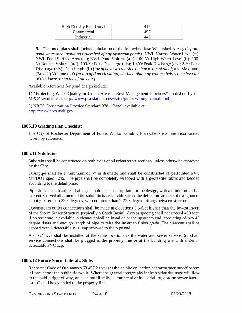
CN 66 68 70 72 74 76 78 80 82 84 86 88 90 Runoff (in.) 0.21 0.24 0.28 0.335 0.39 0.45 0.515 0.59 0.67 0.75 0.85 0.945 1.06 4. In addition to the dead storage water quality volume indicated above, the pond shall have at least the 20 year dead sediment storage volume (below the pond normal water level) per the following table:
Land Use 20 Year Sediment Vol. (Cu. Ft/Acre) Low Density Residential 265
Medium Density Residential 343
ENGINEERING STANDARDS PAGE 18 03/23/2018
High Density Residential 419 Commercial 497
Industrial 443 5. The pond plans shall include tabulation of the following data: Watershed Area (ac) [total pond watershed including watershed of any upstream ponds]; NWL Normal Water Level (ft); NWL Pond Surface Area (ac); NWL Pond Volume (a-f); 100-Yr High Water Level (ft); 100-Yr Bounce Volume (a-f); 100-Yr Peak Discharge (cfs); 10-Yr Peak Discharge (cfs); 2-Yr Peak Discharge (cfs); Dam Height (ft) [toe of downstream side of dam to top of dam]; and Maximum (Breach) Volume (a-f) [at top of dam elevation, not including any volume below the elevation of the downstream toe of the dam].
Available references for pond design include:
1) “Protecting Water Quality in Urban Areas – Best Management Practices” published by the MPCA available at: http://www.pca.state.mn.us/water/pubs/sw-bmpmanual.html
2) NRCS Conservation Practice Standard 378, “Pond” available at: http://www.nrcs.usda.gov
1005.10 Grading Plan Checklist
The City of Rochester Department of Public Works “Grading Plan Checklists” are incorporated herein by reference.
1005.11 Subdrains
Subdrains shall be constructed on both sides of all urban street sections, unless otherwise approved by the City.
Drainpipe shall be a minimum of 6” in diameter and shall be constructed of perforated PVC Mn/DOT spec 3245. The pipe shall be completely wrapped with a geotextile fabric and bedded according to the detail plate.
Pipe slopes in subsurface drainage should be as appropriate for the design, with a minimum of 0.4 percent. Curved alignment of the subdrain is acceptable where the deflection angle of the alignment is not greater than 22.5 degrees, with not more than 2-22.5 degree fittings between structures.
Downstream outlet connections shall be made at elevations 0.5-feet higher than the lowest invert of the Storm Sewer Structure (typically a Catch Basin). Access spacing shall not exceed 400 feet, if no structure is available, a cleanout shall be installed at the upstream end, consisting of two 45 degree risers and enough length of pipe to raise the invert to finish grade. The cleanout shall be capped with a detectable PVC cap screwed to the pipe end.
A 6”x2” wye shall be installed at the same locations as the water and sewer service. Subdrain service connections shall be plugged at the property line or at the building site with a 2-inch detectable PVC cap.
1005.12 Future Storm Laterals, Stubs
Rochester Code of Ordinances 63.457.2 requires the on-site collection of stormwater runoff before it flows across the public sidewalk. Where the general topography indicates that drainage will flow to the public right of way, on each multifamily, commercial or industrial lot, a storm sewer lateral “stub” shall be extended to the property line.

ENGINEERING STANDARDS PAGE 19 03/23/2018
ENGINEERING STANDARDS PAGE 20 03/23/2018
Section 1006 Service Connections
1006.1 Sizing Service Connections
A. Sanitary Sewer
Sizing of Sanitary Sewer services shall be 4" minimum.
All sanitary sewers shall be designed to have sufficient slope to provide mean velocities of 2 fps based on Manning’s formula using an N factor of 0.013.
The minimum elevation of the service shall be established by using the elevation at the top of the main, or riser plus a 2% slope to a point behind the outside edge of the sidewalk in the area of the 10 foot utility easement. Maintain a minimum depth of 7.5 ft below boulevard elevation.
B. Water
Small water services are to be 1 inch, 1 1/2 inch or 2 inch inside diameters only. For common trench installation a vertical separation of 12” (minimum) is required. Water services are to be sized to provide the design flow rate while maintaining a minimum 20 psi residual pressure at the last plumbing or process fixture connected to the service line. Rochester Public Utilities will provide static pressure and fire flow capacity information from a water distribution system computer model as an aid to water service line, interior plumbing, and fire sprinkler system designers. Designers are to anticipate water meter and required backflow preventer head losses in sizing water services.
If a water service is sized to serve a fire sprinkler system and domestic water consumption is anticipated to be small, construction of a separate small water service to provide for the domestic water service needs is recommended.
1006.2 Pipe Material
A. Sewer Service Pipe shall conform to the following: 1. Polyvinyl Chloride (PVC) SDR 26 conforming to ASTM D 2241 (not permitted within 1 foot of footing or more than 10 feet from the property line). 2. Polyvinyl Chloride (PVC) SDR 35 or SDR 26 conforming to ASTM D 3034 (not permitted within 1 foot of footing or within 10 feet of the water). 3. Cast iron soil pipe and fittings shall be the "Service Weight, Centrifugally Spun" grade and shall conform to ASTM A74-75. 4. Ductile iron pipe shall conform to ANSI 21.51.
B. Water Service Pipe shall conform to the following: Pipe 2” diameter or smaller is to conform to the requirements of ASTM B88 for Seamless Copper Water Tube, Type K, Soft Annealed Temper. Water services larger than 2” diameter are to be ductile iron.

ENGINEERING STANDARDS PAGE 21 03/23/2018
Section 1007 Pumping Station
1007.1 Lift Station Design A. The lift station shall be designed as a packaged system from one supplier incorporating
components from multiple manufacturers. B. Wet well shall be designed to equalize flow to minimize pump starts per hour to less than 2 for
average future design flows. There shall be minimum of one foot clearance from high water level to lowest sewer discharge line.
C. Pumps shall be submersible solids handling pumps designed for raw sewerage service. 1. Manufacturers shall be Flygt, KSB, or approved equal. 2. Pumps shall have non clog type impellers and be capable of passing at minimum a 3 inch
solid. 3. Lift Station shall have 1 duty, 1 standby pump and each pump shall be designed to
independently handle future peak wet weather flow. 4. A guiderail system shall be used to allow easy pump removal from service without
requiring physical entry into the wet well by maintenance personal. Lockable service access hatch covers shall be provided to allow pump removal without removal of wet well top.
D. Check valve vault shall be separate from wet well. 1. One check valve shall be dedicated to each pump. Each check valve discharge shall have
plug valve installed for isolation. 2. Check valve vault shall have 3” drain from vault discharging to wet well with rubber
flapper on end of drain pipe to prevent off gas and routed to bottom of wet well to maintain submergence.
3. Check valve vault shall have lockable hatch for access and removal of valves. E. A vent shall be installed on top of the wet well and check valve vault with opening facing
downward and insect screen covering the opening. F. All pipe penetrations shall be sealed with link seal. G. All structures shall be designed by structural engineer registered in the state of Minnesota. H. Lift Station design shall, at a minimum, follow the most recently published Ten State Standards
in addition to listed requirements. Where this document overlaps Ten State Standards, this document shall apply.
I. AutoCAD files of electrical and lift station drawings shall be submitted to the Water Reclamation Plant for record. One set of operation and maintenance manuals shall also be submitted to the Water Reclamation Plant for record.
J. Two sets of operation and maintenance manuals shall be submitted to Owner/Operator of lift station.
1007.2 Forcemain Design A. The forcemain shall be sized with a maximum diameter to assure flow greater than 2 ft/s when
operating. Velocities less than 5 ft/s are desirable for energy efficiency goals. Discharge piping shall be sized, wherever possible, with a minimum diameter of the largest spherical solid passed through the pumps. Minimum forcemain pipe diameter of 3 inches.
B. An air/vacuum valve suitable for use in wastewater shall be installed with an isolation valve located at the high point of the discharge piping of the forcemain inside a valve vault.
1007.3 Coatings and Materials
ENGINEERING STANDARDS PAGE 22 03/23/2018
A. All miscellaneous hardware, nuts and bolts, pump guiderails, hatches, control panels, and conduit shall be 316 stainless steel.
B. All piping shall be cement mortar lined ductile iron pipe primed at the factory. C. Interior walls, floor, and ceiling of wet well and check valve vault shall be coal tar epoxy or
polyurethane coated or approved coating as submitted by contractor and approved by engineer. D. All piping and valves shall be final field coated. E. Stainless steel materials shall not be coated with exceptions to bolts connecting coated piping and
valves.
1007.4 Site Layout A. Where potable water supply is located within 300 feet of lift station, install fire hydrant within
100 feet of lift station wet well and outside of any fenced area. B. All structures and equipment pads shall have top of concrete at same elevation and shall be
located above 100 year flood elevation. C. Soil shall come up to two inches below top of concrete and slope away from structures. D. Four inches of Class 5 aggregate surfacing shall be placed on the subgrade within lift station area. E. All vaults, panels, hatches, or other access to equipment or electronics shall be designed to accept
a pad lock. F. Fencing is not required. Fence shall be 8 ft tall galvanized metal fencing plus 3 strand barb wire
on top. Fence gate shall include 12ft wide opening with two 6ft gates. Structures and entrance shall be situated to allow 1 ton pickup access to lift station and valve vault. Coordinate access acceptability with contracted maintenance provider or maintenance staff.
1007.5 Power A. One electrical primary power source is required with backup power. B. Natural gas, diesel, or propane backup engine generator with automatic transfer switch shall be
provided. Generator shall rest on concrete pad. C. Nema 4 electrical cabinets and stainless steel hardware. Control and power cabinets shall be
mounted above grade to concrete pads. D. Pump power cable shall be continuous cable without splices from motor to electrical junction
located just outside of wet well. Another cable shall be routed from junction cabinet to electrical cabinet where drive is located and have a seal off located nearest the junction cabinet.
E. Pumps shall have 3 phase motors. F. When variable speed drives are required, ABB Drives shall be used without exception. G. Lift station shall have 120V receptacle located on cabinet and working light with switch located
on exterior of cabinet or remotely on a pole.
1007.6 Instrumentation A. All instrumentation cables shall be continuous from instrument to junction box located outside of
the wet well and include seal offs for cables routed from junction box to control cabinet. B. Controls shall rotate duty and standby pumps. C. Power and control wire conduits shall be separate. D. Zetron units shall be supplied for telemetry with 4 wire data circuit telephone connection, or
coordinate with proposed service contractor for appropriate telemetry. E. Floats are required for wet well level and alarms.
1. Flygt ENM-10 floats shall be used. No alternates allowed. 2. High Level Alarm float and Low Level Alarm float.

ENGINEERING STANDARDS PAGE 23 03/23/2018
3. Low All Off float. 4. Lead Pump Start float. 5. Lag Pump Start float. 6. Other floats deemed necessary by Engineer.
F. Check valve lever arms proximity switches to verify pump is pumping wastewater or mag meter. G. Pump On/Off H. Pump Faults

ENGINEERING STANDARDS PAGE 24 03/23/2018
Section 1008 Erosion and Sediment Control
1008.1 Required Documentation 1. A “Stormwater Pollution Prevention Plan” (SWPPP) shall be incorporated into the construction plans & specifications and/or grading plan. The plan shall conform to the Department of Public Works “Grading Plan Checklist”, applicable Minnesota Pollution Control Agency (MPCA) permit requirements, and “Best Management Practices” as published by the MPCA. The plan shall include adequate temporary and permanent erosion and sediment control measures. 2. The following statement shall be placed on all plans for projects with excavation “Erosion and sediment control measures shown are minimum and additional measures must be installed as needed to control erosion and sediment.” 3. The Owner and Contractor shall obtain an NPDES Storm Water Construction Activity permit from the MPCA, and any other permits required. The designated Erosion Control Supervisor shall coordinate project information and complete inspection and maintenance information on the City’s erosion and sediment control website (PermiTrack).
1008.2 Construction Requirements 1. The construction shall comply with the project SWPPP and applicable MPCA permit requirements, as necessary to prevent off-site erosion and/or sedimentation and tracking, and shall include final stabilization. 2. Best Management Practices (BMPs) for erosion and sediment control shall be established on all down-gradient perimeters before grading is commenced, and shall be regularly maintained and remain in place until final stabilization. 3. The NPDES Permit Holder shall be responsible for cleaning and maintenance of the storm sewer system (including ponds, pipes, catch basins, culverts, and swales) within the subdivision and the adjacent off-site storm sewer system that receives storm water from the subdivision. If erosion and sediment control measures taken are not adequate and result in downstream sediment, the NPDES Permit Holder shall be responsible for cleaning out or dredging downstream storm sewers and ponds as necessary, including associated restoration. The NPDES Permit Holder shall follow all instructions it receives from the City Engineer concerning the cleaning and maintenance of the storm sewer system. The NPDES Permit Holder and/or the Developer’s obligations under this paragraph shall end two (2) years after the public improvements in the subdivision have been accepted by the City Engineer, or after the NPDES Notice of Termination (NOT) whichever is greater. 4. The NPDES Permit Holder shall be responsible for cleaning all streets in the subdivision and adjacent to the subdivision from silt and dirt from the subdivision for a period of two (2) years ending when the streets have been completed and accepted by the City Engineer, or after the NPDES Notice of Termination (NOT) whichever is greater. 5. After the site has been finally stabilized, all permanent storm water ponds shall be cleaned to original plan cross-section, all temporary sediment control measures (such as silt fence) shall be removed, temporary sediment basins shall be re-graded and stabilized, prior to final acceptance by the City Engineer and the NPDES Notice of Termination (NOT).
1008.3 Temporary Erosion and Sediment Control
Temporary erosion and sediment control shall conform to the requirements in the SWPPP to prevent soils and sediment from entering public waters, sewers, streets and adjacent properties.
ENGINEERING STANDARDS PAGE 25 03/23/2018
These temporary control measures include their eventual removal after conditions stabilize.
Contract pay items shall be provided for temporary erosion and sediment control items to facilitate immediate implementation by the NPDES Permit Holder, or as directed by the Local Regulatory Unit or MPCA’s acting agent.
1008.4 Permanent Erosion and Sediment Control
Permanent erosion and sediment control shall conform to the requirements in the SWPPP to prevent soils and sediment from entering the public waters, sewers, streets and adjacent properties.
Contract pay items shall be provided for permanent erosion and sediment control items to, if encountered, facilitate modifications to the original SWPP by the NPDES Permit Holder, or as directed by the Local Regulatory Unit or MPCA’s acting agent.

ENGINEERING STANDARDS PAGE 26 03/23/2018
Section 1009 Decorah Edge Areas
1009.1 General
The objective of this section is to define elements of treatment of public infrastructure systems that traverse through “Decorah Edge” areas (Decorah Edge areas defined in City of Rochester Code of Ordinances, Chapter 59 “Wetland Conservation”, section 59.02., subd. 2). Primary features of the protection measures in this section include:
1. Avoiding “Decorah Edge” areas to the maximum extent practicable. 2. Allowing only Collector or higher classification roadways to transverse across these areas. 3. Allowing only large diameter underground trunk main public infrastructure with appropriate treatment elements to transverse across these areas. 4. For Roadways, require a subsurface drainage collection system. Require the subsurface system to discharge into the surface water storm sewer system, not reentering or infiltrating back into the subsurface system.
The following guidelines were developed to protect our surface/subsurface groundwater migration, hydrogology by ensuring their proper care and protection and to ensure its compatibility with an efficient and dependable infrastructure system.
1009.2 Roadway Plans
Roadways across the Decorah Edge areas should be avoided, if at all possible. Only streets classified as Collectors or higher shall be constructed across the Decorah Edge areas. Roadways through the Decorah areas shall be installed according to the detail plate to mitigate these subsurface flows.
Sub drains shall be constructed through the entire Decorah Edge area for roadway sections, unless otherwise approved by the City.
Drainpipe shall be a minimum of 6” in diameter. The pipe shall be completely wrapped with a geotextile fabric and bedded according to the subdrain detail plate.
Pipe slopes in subsurface drainage should be as appropriate for the design, with a minimum of 0.4 percent. Curved alignment of the sub drain is acceptable where the deflection angle of the alignment is not greater than 22.5 degrees, with not more than 2-22.5 degree fittings between structures.
The alignment of the street shall be perpendicular to the contours to the maximum extent practicable to minimize the Decorah area impacted.
1009.3 Underground Utilities
Public Utilities through the Decorah areas shall be installed according to the detail plates.
Underground utilities such as storm sewer, sanitary sewer and watermain shall not allow the subsurface water to flow along the pipe.
Anti seep collars shall be installed according to the detail plate to mitigate subsurface flows.

ENGINEERING STANDARDS PAGE 27 03/23/2018
Section 1010 Tree Planting, Preservation, and Protection
1010.1 Description
The City of Rochester acknowledges the importance of trees to the community’s health, safety, welfare, and tranquility. Trees increase property values, provide visual continuity, provide shade and cooling, decrease wind velocities, control erosion, conserve energy, reduce stormwater runoff, filter airborne pollutants, reduce noise, provide privacy, provide habitat and food value, and release oxygen.
1010.2 Definition of Terms
A. Tree Protection Zone:
A specified area above and below ground and at a given distance from the trunk set aside for the protection of a tree’s roots and crown to provide for the viability and stability of a tree to be retained where it is potentially subject to damage by development.
Tree Protection Zone by type shall be determined by the City Forester.
Minimum area specified shall be 4 times the diameter, measured 4’-6” above the ground.
B. Hand Work Zone:
A circumscribed square area around the Tree Protection Zone in which only hand held operating tools shall be used for removal or construction activities.
1010.3 Engineering Requirement
Trees and other vegetation worth preserving are to be protected and preserved to the maximum extent feasible during construction. Only those trees and other vegetation that have been evaluated as being necessary to be removed to allow for new construction will be removed. Trees and other vegetation that have been evaluated as worth saving and designated to remain will be properly protected during construction to maximize their survival rate. In order to achieve an appropriate balance between protecting trees and allowing necessary construction, the practices that follow will be employed.
All trees to be preserved on the property and all trees adjacent to the property shall be protected and maintained against damage during construction. The Engineer and Owner are to survey the job site before work is scheduled. Limits of disturbance are to be determined by the Engineer and Owner before work begins. Storage sites for soil, sand, pipe, hardware and equipment are to be determined by the Owner. Vehicle access routes are to be determined. All workers on the site shall be educated in tree preservation practices. Tree protection devices shall be placed before material deliveries, excavation, or grading begins and is to be maintained in good repair for the duration of the construction work, unless otherwise directed. Tree protection shall remain until the landscape restoration work begins
1010.4 Construction Requirement
Protection of trees during construction (including remodeling and demolition): Prior to any site work, all trees to be preserved must be protected, signed, and maintained, in accordance with the Tree Preservation and Protection Standards. The level of tree protection by type will be as determined by the City Forester.
Tree Protection
ENGINEERING STANDARDS PAGE 28 03/23/2018
Trees in the area of disturbance and in the vehicle access route are to be protected by fencing in the following manner:
No material shall be stored or construction operation shall be carried on within the tree protection fencing.
No protective devices, signs, utility boxes or other objects shall be nailed to the trees to be retained on the site.
Tree protection fencing shall be erected and approved by the Engineer at least 24 hours before construction begins.
Grade Changes
Grade cuts of 6” or more, shall be reduced or eliminated within the drip line and no cuts are allowed in the tree protection zone.
When fill of 4” or more is necessary within the drip line of a tree, a tree well shall be required and no fills are allowed in the tree protection zone.
Areas under tree drip lines disturbed by construction activity shall be mulched with a 2-3” deep layer of shredded bark mulch. Mulching shall be done within 4 hours of disturbance.
Trenching and Tunneling
Trenching shall be done outside the tree protection zone. Trenchless techniques hall be employed within the tree protection zone.
Pruning of branches shall be done under the requirements and direction of the City Forester.
ENGINEERING STANDARDS PAGE 29 03/23/2018
Section 1011 Project Development
1011.1 General
Public Works and the City-Owner Contract process require specific meetings to improve communication and coordination through the project development. They are intended to facilitate the design of infrastructure and do not replace the development meetings hosted by the Planning Department or any other city department.
The City-Owner Contract process meetings include:
1. Predesign meeting 2. Pre-grading plan preparation meeting 3. Grading plan pre-submittal meeting 4. Preconstruction meeting 5. Construction progress meetings
1011.2 Predesign meeting
The meeting should be face-to-face conferences. For projects where the City-Owner construction is minor in scope (less than $25,000), the predesign meeting may be via phone conference call or other telecommunication methods.
A. Required attendees 1. City Engineering staff -Infrastructure Manager or Engineering Manager and City Owner Engineering Tech 2. Site design engineer- Professional signing the plan and lead designer
(a) City-Owner designer shall provide evidence of ‘errors and omissions’ insurance. 3. Geotechnical professional
B. Recommended attendees 1. City staff -RPU representative, Grading/drainage plan review engineer, Land Development Representative, and County Engineer representative for county road work
(a) Design consultant - Planner or architect, Project inspector, Hydraulics modeler, and Pavement design engineer
2. Owner or their representative 3. Contractor representative
C. Material available for the meeting 1. Required
(a) Most advanced site plan available (preliminary plat, GDP, preliminary grading plan). Plan should include:
Contours Existing utilities Lot/building layout
(b) Proposed details (street section, special features, etc.) (c) Geotechnical information available
2. Recommended (a) Information related to the hydraulic report

ENGINEERING STANDARDS PAGE 30 03/23/2018
(b) Information related to the pavement design (c) Utility service loading estimates (d) Preliminary utility layouts (e) Special site challenges (f) Preliminary traffic control plan
D. Discussion Topics 1. Plan format and content 2. Development goals related to infrastructure 3. Project schedule 4. Document/plan submittal schedule/content/to who at city 5. Special challenges
(a) Ground water and unsuitable soils (b) Is rock excavation expected? Excavated rock handling plan (c) Wetland protection plan. Wetland soils handling plan
6. Utility extension through property to the next property 7. Construction traffic management and public traffic control 8. “Public or Private” labeling for utilities 9. City-Owner vs. Permit work 10. Private utilities (gas, telephone, cable) coordination 11. Construction noise and dust control
1011.3 Pre-grading plan preparation meeting
This meeting may be combined with predesign meeting to cover the following considerations.
1. Designer needs to review the grading plan checklist, and have a general understanding of the site topography and drainage patterns. 2. Topics of discussion may include:
(a) Unusual grading and drainage issues. (b) Will a Substantial Land Alteration (SLA) be required? (c) Will a regional storm water treatment facility be used or constructed?
1011.4 Grading plan pre-submittal meeting
The goal of the grading plan pre-submittal meeting, arranged by calling Public Works, is to briefly review the grading plan and drainage report, prior to acceptance for full review by Public Works. The expectation is that the grading plan, draining report, and all required documentation is fully complete and the documents meet all the City requirements.

ENGINEERING STANDARDS PAGE 31 03/23/2018
Section 1012 Standard Plans
1012.1 General
In order for the City to have standardized construction plans and record drawings, the City requires drawings be submitted in AutoCAD file format, utilizing Civil 3D elements and Adobe PDF.
The information shown on plans should follow the Mn/DOT Sample Plan format to depict what the end product will look like and provides guidance to those roadway designers preparing the individual plan sheets for roadway construction projects. City survey and CAD deliverables to be used shall be obtained at the start of a project to ensure current standards and formats are followed correctly.
1012.2 Modifications to the Mn/DOT Sample Plan
In addition to the guidelines set forth by the Sample Plan, the guidelines listed below shall be followed:
A. General
All sheets shall be reproducible on standard D-size sheets (22" x 34"). Scale 1” = 20’ where there are more than two underground facilities (i.e. sewers, watermains, subdrains) or sheets that are otherwise be crowded due to curvature, etc. On large simple detail plans a scale of 1” = 40’ can be used.
All parcels shall be properly labeled with lot and block numbers and plat name, or Parcel Identification Number (PIN) in unplatted areas. Developed parcels shall have their address shown on the plan.
Existing utilities shall be shown in both plan and profile, labeled with stationing as existing.
All match-like breaks shall be clean with reference points clearly marked. All plans, which are broken by a match line, shall be on the same or consecutive sheets.
All sewer (sanitary, storm and subdrain) and watermain shall be shown in the profile with the appropriate information such as size, material, grades, invert elevations, etc.
B. Title sheets
Provide signature block for RPU-Water Division (if plans include watermain), Manager of Engineering and Director of Public Works.
C. Grading and Paving Plans
Provide elevations at 25’ intervals for property lines, top of curb, centerline, all lot corners on property line, all curb returns and mid points, and intersection layouts.
Plot top of curb profiles.
Typical sections including structural section to be shown on the Title Sheet, Detail Sheet or Plan View.
D. Sewer, water and service connection plans.
Identify fittings and structures on the plan view as follows:
(a) Sanitary Sewer........ M.H. No. 1, M.H. No. 2, etc. (b) Watermain .............. W-1, W-2, etc.

ENGINEERING STANDARDS PAGE 32 03/23/2018
(c) Storm Sewer ........... M.H. S-1, S-2, CB No. 1, CB No. 2, etc. (d) Subdrains ................ M.H. SD-1, SD-2, etc.
Notes for fittings and structures shall include the station and relationship to centerline. For structures, also provide the structure type, diameter, casting type, ring and center of invert elevation for inlets and outlets in the notes. Provide the center invert grades on the profile, along with pipeline grades at 25ft intervals.
All hydrants are to be at required height (see Standard Plates) after lawns, boulevards, etc. are finished (sod, seed, etc.) This will be the contractor’s responsibility. Provide break-off elevations on hydrants.
All sanitary sewer services shall be drawn on the plan to the intended location. The station of the wye, the station and invert elevation of all sanitary sewer services at the end of the service in the 10 foot utility easement area and, and the elevation at the service shall be shown on the plans. If risers are installed, the height of each shall be indicated on the plans and also drawn on the profile.
The size and type of all sanitary sewer and water services shall be noted on the plans. Service connections shall be centered on the lots and shall terminate within the 10 foot utility easement area behind the sidewalk. A curb stop and box shall be placed in the boulevard area for the water service. The linear dimension from the property line to the service connection shall be shown on the record drawings.
E. Sidewalk and Bikeway Plans
Show sidewalk or bikeway as construct or future, with widths and distance from property lines on plan views.
Sidewalks with accessible ramps shall be placed within the curb return area at all intersections, except roundabouts / traffic circles.
ENGINEERING STANDARDS PAGE 33 03/23/2018
Section 1013 Submission of Plans
1013.1 Plans and Specifications 1. Submit one set of the pavement and geotechnical report, plans, and specifications to the Public Works Manager of Engineering for review and comment in Adobe PDF format. If the project includes watermain construction, also submit one set to Rochester Public Utilities (RPU) Water Division for review & comment. If the project includes private sewer systems also submit one to Rochester Building Safety Department for review and comment. 2. The Consultant shall obtain a Minnesota Department of Health permit for watermain extensions and a Minnesota Pollution Control Agency permit for sanitary sewer extensions. 3. After approval by the Director of Public Works, submit the electronic files together with signed title sheet to the City of Rochester Public Utilities (RPU) Water Division who will forward on to the appropriate City agencies. 4. In addition, on publicly bid contracts, submit 10 paper copies, or as directed by the Engineer.
1013.2 Estimates
Enter and use standard bid items from the City eGram internet site for all publicly let contracts. As Built quantities shall be provided with the record drawings.
1013.3 City-Owner Contracts 1. Submit the City-Owner Contract Request form to the Public Works Land Development Section. The Public Works Department staff will prepare and return a Contract for execution within 7 business days. 2. Submit: the Contract executed by the Owner, Contractor, and Engineer; the bond; and certificate of insurance; to the Public Works Land Development Section at least 10 business days before the City Council meeting at which the Contract will be considered (meetings are normally every 1st & 3rd Monday of the month). 3. Not later than the Wednesday of the week preceding the City Council meeting,
(a) The plans & specifications must be approved and copies submitted, (b) Any associated grading plan and drainage plan must be approved, (c) The Owner must have signed a Development Agreement, if required, for the project,
and (d) The Owner must have filed the Final Plat or Site Plan with the Planning Dept.
1013.4 Electronic Drawings
The Consultant shall verify and submit an electronic drawing file for the entire plan set, and shall contain an overall plan view drawing containing control point coordinate information accurately referenced to Olmsted County Project Coordinates (NAD83 coordinate base).
For projects with watermains, in addition to providing the required information to Public Works Department, a copy of this file shall be provided directly to Rochester Public Utilities (RPU).
The drawing set shall consist of all related support files required to reproduce the electronic drawing file, as a hard copy, in the current City Civil 3D, AutoCAD format. Support files required by the

ENGINEERING STANDARDS PAGE 34 03/23/2018
City will include any font files (*.shx) not supported by AutoCAD, external reference drawings (AutoCAD Xref), sheet set manager, and plot configuration files (*.pcp, *.pc2, *.pc3…etc.). If software license agreements do not allow distribution of third party support files, then an AutoCAD supported equivalent shall be substituted prior to delivery to the City.
It is required that all files be in AutoCAD™ format. Formats, translations, etc., and the accuracy of data contained therein will be the total responsibility of the contracted source. The files delivered under contract must work in the AutoCAD™ environment as described above with no adjustments, modifications, translations or alterations while retaining all required element properties.
1013.5 Record Drawings
All record drawings shall be submitted in electronic (Civil 3D, AutoCAD and Adobe PDF) format. The plans shall be clearly legible drawings with unnecessary construction information removed (contours, trees, shrubs, fences, etc.). Place proper notes and statements, (i.e. type of alternate pipe used) on all sheets. All hydrants shall have benchmarks on them.
Record drawings on all public and private stormwater management ponds and drainage conveyance facilities are required. Plans shall indicate finished contours at two (2) foot intervals, normal water elevation, high water elevation, and the acre-feet of storage for each ponding area along with the final storm sewer plans.
The record drawing plans shall be submitted to the City Engineer within 1 month of the initial acceptance/commencement of the warranty period. Failure to submit the record drawings within the required 1-month period may result in an extension of the project warranty period for a length of time equal to the delinquency in plan submittal.
ENGINEERING STANDARDS PAGE 35 03/23/2018
Section 1014 Construction Supervision
1014.1 Pre-Construction Conference
As soon as possible after the project has been approved, the Engineer should arrange a meeting for the purpose of reviewing contract requirements, construction details, work schedules and any items peculiar to the project. The meeting should be face-to-face conference. For projects where the City-Owner construction is minor in scope (less than $25,000), the preconstruction meeting may be held on-site.
Prior to this meeting the attendees should study the plans and become familiar with the project site to be well informed as to the requirements and existing conditions.
A. Required attendees 1. City Engineering staff - City Owner Engineering Technician 2. Owner or their representative 3. Construction phase consulting engineer 4. Project inspector(s) 5. Geotechnical professional 6. Contractor –project superintendent and on-site foremen
B. Recommended attendees 1. City staff -RPU representative and County Engineer representative for county road work 2. Contractor’s safety officer, ESC supervisor, others as appropriate for the specific project 3. Utility company representatives (invitation required, attendance optional) 4. Subcontractor representatives 5. Other stakeholders with whom construction coordination would benefit the project.
C. Material available for the meeting 1. Required
(a) Approved construction plans and specifications (b) Permits; DNR, NPDES, MPCA, MDH, others appropriate for the project. (c) Geotechnical report (d) Pavement design report (e) List of subcontractors and material suppliers (f) Traffic control plan.
2. Recommended (a) Shop drawings (b) Other materials appropriate for the project
3. Discussion Topics (a) Project Staging & Schedule; Proposed Starting Date; Completion Date; Working
Hours & Days (b) Construction Observation / inspection requirements for each phase of work (c) Geotech / Materials Testing (d) Traffic control (e) Installation of underground utilities (f) Trench backfill and compaction
ENGINEERING STANDARDS PAGE 36 03/23/2018
(g) Street grading, base, aggregate, and pavement operations (h) NPDES requirements and construction sequencing; Erosion & Sediment Control /
Restoration (i) Special Provisions (j) Execution of work (k) Required stage inspection; attendees, schedule, responsibilities, methodologies, (l) Supplemental Agreements (m) Utility conflicts and accommodations (n) Weekly Construction Meeting Day/Time (o) One Office documentation requirements (p) Clean-up / trash removal (q) Construction workforce private vehicle parking (r) Respect for others (s) Work site safety (t) Security (u) Hazardous materials (v) Noise Ordinance (w) Shop Drawings (x) Project close out requirement; materials certifications, testing results, As-Builts
1014.2 Construction Progress Meetings
The meeting should be held on-site. A common schedule for the meeting is weekly during the full time construction activity. During intermittent construction and during winter project shut-down, less frequent meeting are appropriate.
A. Required attendees 1. City Engineering staff - City Owner Engineering Tech 2. Construction phase consulting engineer 3. Project inspector(s) 4. Contractor –project superintendent and on-site foremen
B. Recommended attendees 1. Geotechnical professional – when appropriate for work being conducted 2. If the project work indicates the need, additional city staff, RPU representative, County Engineer representative for county road work 3. Contractor’s safety officer, ESC supervisor, others as appropriate for the specific project 4. Utility company representatives (invitation required, attendance optional) 5. Owners representative 6. Subcontractor representatives 7. Other stakeholders with whom construction coordination would benefit the project
C. Material available for the meeting 1. Required
(a) Approved construction plans and specifications

ENGINEERING STANDARDS PAGE 37 03/23/2018
(b) SWPPP and PermiTrack reports. (c) Shop drawings (d) Field diary records.
2. Recommended (a) Other materials appropriate for the project
3. Discussion Topics for phase of work under way or planned for the near future (a) Project Staging & Schedule; Proposed Starting Date; Completion Date; Working
Hours & Days (b) Construction Observation / inspection requirements for each phase of work (c) Geotech / Materials Testing (d) Traffic control (e) Installation of underground utilities (f) Trench backfill and compaction (g) Street grading, base, aggregate, and pavement operations (h) NPDES requirements and construction sequencing; Erosion & Sediment Control /
Restoration (i) Special Provisions (j) Execution of work (k) Required stage inspection; attendees, schedule, responsibilities, methodologies, (l) Supplemental Agreements (m) Utility conflicts and accommodations (n) Weekly Construction Meeting Day/Time (o) OneOffice documentation requirements (p) Clean-up / trash removal (q) Work site safety (r) Construction workforce private vehicle parking (s) Respect for others (t) Security (u) Hazardous materials (v) Project close out requirement; materials certifications, testing results, As-Builts
1014.3 Notice to Proceed
The City Engineer will issue a “Notice to Proceed” after the City has executed the City-Owner Contract (for privately let contracts) or the construction contract (for publicly let projects).
1014.4 Surveying
Surveying work includes: complete staking during construction, diaries and survey notes, final benchmarks on hydrants, etc. Survey notes and diaries will be made available to Public Works upon request.
1014.5 Inspection

ENGINEERING STANDARDS PAGE 38 03/23/2018
Engineering supervision ensures completion of construction contracts according to contract requirements; provides technical supervision for construction projects; conducts or provides oversight of all testing; coordinates the activities of public utilities, contractors, and other governmental agencies on construction projects; documents contract work progress for payment of the contractors; keeps property owners, news media, other governmental agencies, and the public informed of construction operations within the area; provides requested technical assistance to other governmental agencies on their construction projects; and advises contractor of traffic safety and control measures. Maintains field records for record drawings. Inspection records, notes, and diaries will be made available to Pubic Works upon request.
The following qualifications and expectations are required on City-Owner Contracts:
A. Inspector Qualifications 1. Experience (must meet the following)
(a) Must have a minimum of 2 years of civil engineering technician education and 2 years of infrastructure installation field experience (or a combination that is equivalent).
(b) May be graduates from an accredited college engineering program (engineering, construction management, landscape architecture, or similar program). Must have MnDOT certifications within 2 years. Required to work under a mentor (with them at least 20% of the time) during this interim time. Mentors must possess all requirements of a fully qualified / certified construction observer / inspector.
2. Certification Required (must meet all the following) (a) Must have Mn/DOT Certifications (Aggregate Production, Grading & Base I & II,
Bituminous Street, and Concrete Field I & II). If coming from another state, must show equivalent course work and will be allowed to serve as qualified / certified construction observer without mentor, but must take all Mn/DOT certifications within 3 years.
(b) Must have Erosion & Stormwater Management – Construction Site Management certification from University of Minnesota (or comparable training).
(c) If performing construction observation / inspection of underground construction activities (i.e. sewer and water), must have the Minnesota Pipe Layers Card certification (or equivalent).
(d) Documentation Filed with Public Works - Consulting Engineering firms are required to submit to Public Works the records for each individual construction observer / inspector annually, but no later than 2 weeks prior to performing any field construction observation / inspection tasks performed by that individual.
B. Inspection Expectation
For projects with normal levels of complexity and site condition challenges, the following on-site field inspection is the required minimum expectation:
Activity Level of Inspection
Time (%)
Site Clearing & Grubbing Part Time 25% General site grading & excavation Part Time 25% Underground utility work & trench compaction
Full Time 100%
Street subgrade preparation / compaction Full Time 100% Aggregate Base placement Part Time 50% Aggregate Base compaction / proof roll test Full Time 100% Curb & Gutter preparation Part Time 50% Curb / Gutter string line check / verification Full Time 100%
ENGINEERING STANDARDS PAGE 39 03/23/2018
Curb / Gutter pouring Full Time 100% Bituminous non-wear Full Time 100% Bituminous non-wear prior to wear Full Time 100% Bituminous wear placement Full Time 100% Concrete street placement Full Time 100% All required Stage testing of piping, subgrade, base and paving
Full Time 100%
Other activities as directed by engr or city As required
Part Time – means construction observer / inspector is on site during critical times (as outlined above and in consultation with the Project Engineer), and may not be on site during all work performed by the contractor for that task item. Part time is a percentage comparison to the preliminary schedule supplied by the contractor at the pre-construction meeting and is used in preparing the construction observation budget.
Full Time – means construction observer / inspector is on site during the time the contractor is actually putting work in place. Includes daily site visits. Construction observation / inspection will be documented and recorded using the One Office program.
1014.6 Utility Testing 1. Watermain Testing. Coordinate watermain loading, pressure testing, conductivity test, bacteria testing, and visual inspection on valves and hydrants with the RPU Water Division. Only RPU personnel shall operate valves and hydrants and perform visual inspection on valves and hydrants. 2. Sanitary Sewer Testing. Observe the test and submit the certification of sanitary sewer air & deflection testing and request for televising to the City Engineer. The City Engineer will schedule televising by City forces. Sanitary sewers will generally not be televised until the bituminous base has been placed and the castings are set to final grade.
1014.7 Detailed Stage Inspections
The Engineer shall notify the City Engineer 48 hours prior to “stage inspections.” The inspections will be performed in the presence of the Contractor, the project Consulting Engineer, and Public Works Department personnel. Inspections shall be performed at the following construction stages, unless otherwise indicated in the Contract. Submit the required material test reports to the City Engineer prior to or at the respective “stage inspection.” Any areas failing the stage inspection must be corrected and re-tested for compliance prior to re-inspection.
1. Subgrade Preparation. Visual inspection of soils and conditions. Test rolling – one pass of a 7-ton per axle vehicle in each travel lane and parking lanes; one wheel shall be within the curb section during the parking lane pass. Prior to the inspection, submit test results to the City Engineer for utility trench compaction, embankment compaction, and subgrade compaction. 2. Aggregate Base. Visual inspection of compaction. Test rolling as above, except no deflection allowed. Prior to the inspection, submit test results for aggregate quality, aggregate gradation, and aggregate compaction. Submit base course bituminous trial mix design to the City Engineer prior to paving.
Yield calculations are required for aggregate base. Use 135 pounds per cubic foot for aggregate base. Calculations must be submitted to Public Works prior to placing bituminous base
3. Bituminous Base and Concrete Curb & Gutter. Visual inspection for settling and

ENGINEERING STANDARDS PAGE 40 03/23/2018
cracking. Prior to the inspection, submit test results for concrete tests of the curb, bituminous mix design (prior to paving), aggregate quality, and compaction.
Bituminous pavement material shall be tested in accordance with the Mn/DOT schedule of materials control. Except, bituminous pavement shall be cored for all projects with bituminous quantities exceeding 100 tons
4. Grading. Visual inspection of site grading, consistent with provisions of City of Rochester Code of Ordinances, Chapter 50, Section 50.03, Subd. 2., B. Prior to inspection submit lot elevations at property corners for Public Works review of vertical and horizontal elevations.
The City’s approval of various stages of the project work shall not constitute an acceptance of the work or the project, and the contractor shall be liable for defects due to faulty construction until the entire work under the Contract or City-Owner Contract is finally accepted by the City as stipulated in the Contract or City-Owner Contract. The Engineer / Inspector shall document all inspections. These documents shall be made available to Public Works upon request.
1014.8 Pavement Quality Assurance using Cores
The Engineer shall notify the City Engineer 48 hours prior to “coring.” The work will be performed in the presence of the Contractor, the project Consulting Engineer, and Public Works Department personnel. Samples shall be taken on all Collector and Arterial Streets, and Commercial Subdivisions at a rate of 1 / 500 ft Block. Core measurements shall be reported for each pavement design material.
If any core thickness measurement shows a thickness deficiency greater than plan thickness minus 1/2 inch, consider the pavement defective and must be corrected, as determined by the City Engineer, between acceptable cores and re-tested for compliance. Submit the required test reports to the City Engineer.
1014.9 Acceptance 1. Project Construction Record. Submit to the City Engineer the Project Construction Record, the material (e.g. pipe) certifications, material test results for bituminous wear course, and any other items listed in the Project Construction Record not previously submitted. 2. Engineer’s Certification of Acceptance. After all Contract construction is complete including corrective work identified by the Engineer, submit the Engineer’s Certification of Acceptance, with Part 1 complete, to the City Engineer. The City will schedule with the Engineer a joint inspection of the project and either:
a) process the initial acceptance and commencement of the warranty period (Part 2 of the form), or
b) return the Engineer’s Certification with instructions for corrections in the work. 3. Record Drawings. Electronic record drawings shall be submitted as in section 1013. 4. Warranty Work. Prior to the end of the two-year warranty, the City Engineer will inspect the project and provide instructions for corrections, if any. Notify the City Engineer when all corrections have been made. 5. Final Acceptance. Upon expiration of the warranty and completion of all corrections, the City Engineer will process Final Acceptance (Part 3 of the Engineer’s Certificate of Acceptance) and provide a copy to the Owner, Contractor, and Engineer.
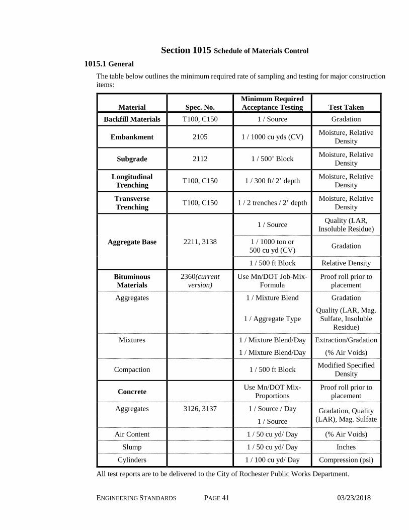
ENGINEERING STANDARDS PAGE 41 03/23/2018
Section 1015 Schedule of Materials Control
1015.1 General
The table below outlines the minimum required rate of sampling and testing for major construction items:
Material Spec. No. Minimum Required Acceptance Testing Test Taken
Backfill Materials T100, C150 1 / Source Gradation
Embankment 2105 1 / 1000 cu yds (CV) Moisture, Relative Density
Subgrade 2112 1 / 500’ Block Moisture, Relative Density
Longitudinal Trenching T100, C150 1 / 300 ft/ 2’ depth Moisture, Relative
Density
Transverse Trenching T100, C150 1 / 2 trenches / 2’ depth Moisture, Relative
Density
Aggregate Base 2211, 3138
1 / Source Quality (LAR, Insoluble Residue)
1 / 1000 ton or 500 cu yd (CV) Gradation
1 / 500 ft Block Relative Density
Bituminous Materials
2360(current version)
Use Mn/DOT Job-Mix-Formula
Proof roll prior to placement
Aggregates 1 / Mixture Blend Gradation
1 / Aggregate Type Quality (LAR, Mag.
Sulfate, Insoluble Residue)
Mixtures 1 / Mixture Blend/Day Extraction/Gradation
1 / Mixture Blend/Day (% Air Voids)
Compaction 1 / 500 ft Block Modified Specified Density
Concrete Use Mn/DOT Mix-Proportions
Proof roll prior to placement
Aggregates 3126, 3137 1 / Source / Day Gradation, Quality (LAR), Mag. Sulfate 1 / Source
Air Content 1 / 50 cu yd/ Day (% Air Voids)
Slump 1 / 50 cu yd/ Day Inches
Cylinders 1 / 100 cu yd/ Day Compression (psi)
All test reports are to be delivered to the City of Rochester Public Works Department.