engineering specifications high pressure … control valves/details... · dynex engineering...
TRANSCRIPT

High Pressure HydraulicsDYNEX ENGINEERING
SPECIFICATIONS
High Pressure, Subplate Mounted VST SERIES
Seated Control Valves 10 000 and 15 000 psi(700 and 1040 bar)
VST Series valves provide reliablehigh pressure venting or directionalcontrol operation.
VSTV and VST22 models are twoposition, two-way valves for venting,unloading, dumping or similar on/off“switching” functions.
VST23 models for three-way direc-tional control are ideal for circuitswhich require locking of actuatorsused in clamping systems, pressesand load holding applications.
The “T” port on these valves must beconnected to tank. For maximum tankport pressures, see “Specifications”on page 2. Also, refer to valvefunctions in “Typical Model Code” onpage 7.
FLOW AND PRESSURE RATINGS
VSTV models are low flow ventvalves rated for 1 gpm (3,8 L/min)nominal with maximum flows to 2 gpm (7,6 L/min). They operatereliably at pressures to 15 000 psi(1040 bar).
VST22 and VST23 models are ratedfor 5 gpm (19 L/min) nominal flow atpressures to 10 000 psi (700 bar).Flows to 10 gpm (38 L/min) arepossible with some models. See“Typical Valve Performance” onpage 3.
BALL-ON-SEAT DESIGN
VST valves are ideal for systemsoperating at higher pressures. Theball-on-seat design provides distinctadvantages compared to spoolvalves.
First, with this design silting cannotoccur. This provides reliable shiftingeven when the valve remainsunactuated for long periods at highpressure.
Second, these are positive sealingvalves, which make them ideal forcircuits requiring load holdingfunctions.
Model VSTV Vent Valve
Model VST22Two Position, Two-Way
Model VST23Two Position, Three-Way
PLUG-IN TERMINAL SOLENOIDS
Standard solenoid plugs simplifyelectrical connections during instal-lation and servicing. These integralthree-terminal, bi-polar plugs fit DIN Connector Standard 43650(Hirschmann GDM 209).
Solenoid models are quiet andweather-tight for extra-long life. Wetarmature design eliminates dynamic
Convenient Hand-Actuated Override
seals and increases the availableshifting forces. Static o-rings preventexternal leakage.
EXPLOSION PROOF SOLENOIDS
Solenoids with special enclosures areapproved by “UL” and “CSA” for usein hazardous locations. These modelsare available for A.C. and D.C.
RELIABLE VALVE SEALING
Tapered o-ring counterbores reduceleakage, by assuring seal retentionin rapid cycling operation.
MANUAL SOLENOID OVERRIDE
Solenoid override pins are madefrom corrosion-resistant brass fortrouble-free operation.
Convenient hand-actuated manualoverride is available as an option.This provides solenoid overridewithout the use of tools.
2
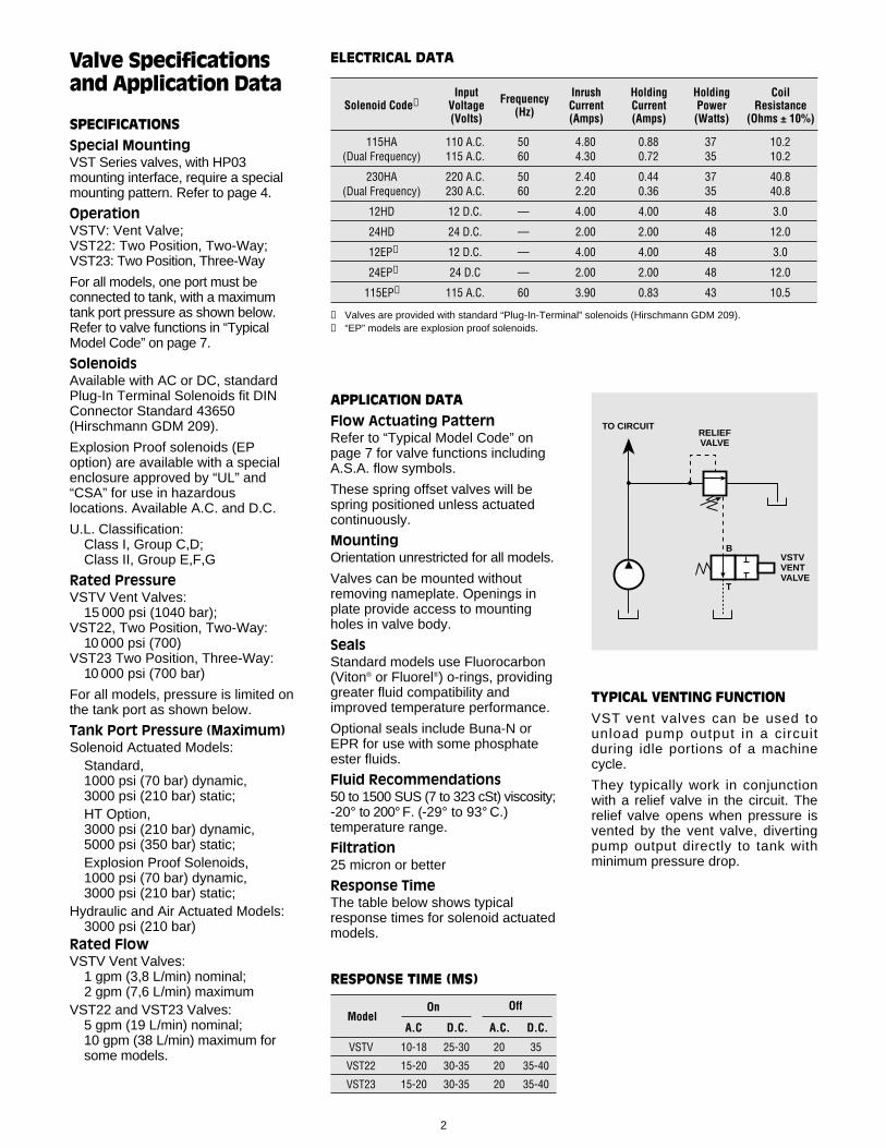
115HA 110 A.C. 50 4.80 0.88 37 10.2(Dual Frequency) 115 A.C. 60 4.30 0.72 35 10.2
230HA 220 A.C. 50 2.40 0.44 37 40.8(Dual Frequency) 230 A.C. 60 2.20 0.36 35 40.8
12HD 12 D.C. — 4.00 4.00 48 3.0
24HD 24 D.C. — 2.00 2.00 48 12.0
12EP➁ 12 D.C. — 4.00 4.00 48 3.0
24EP➁ 24 D.C — 2.00 2.00 48 12.0
115EP➁ 115 A.C. 60 3.90 0.83 43 10.5
➀ Valves are provided with standard “Plug-In-Terminal” solenoids (Hirschmann GDM 209).➁ “EP” models are explosion proof solenoids.
Solenoid Code➀Input
Voltage(Volts)
Frequency(Hz)
InrushCurrent(Amps)
HoldingCurrent(Amps)
HoldingPower(Watts)
CoilResistance
(Ohms ± 10%)
ELECTRICAL DATA
APPLICATION DATA
Flow Actuating PatternRefer to “Typical Model Code” onpage 7 for valve functions includingA.S.A. flow symbols.
These spring offset valves will bespring positioned unless actuatedcontinuously.
MountingOrientation unrestricted for all models.
Valves can be mounted withoutremoving nameplate. Openings inplate provide access to mountingholes in valve body.
SealsStandard models use Fluorocarbon(Viton® or Fluorel®) o-rings, providinggreater fluid compatibility andimproved temperature performance.
Optional seals include Buna-N orEPR for use with some phosphateester fluids.
Fluid Recommendations50 to 1500 SUS (7 to 323 cSt) viscosity;-20° to 200° F. (-29° to 93° C.)temperature range.
Filtration25 micron or better
Response TimeThe table below shows typicalresponse times for solenoid actuatedmodels.
TYPICAL VENTING FUNCTION
VST vent valves can be used tounload pump output in a circuitduring idle portions of a machinecycle.
They typically work in conjunctionwith a relief valve in the circuit. Therelief valve opens when pressure isvented by the vent valve, divertingpump output directly to tank withminimum pressure drop.
TO CIRCUIT
B
RELIEFVALVE
VSTVVENTVALVE
T
VSTV 10-18 25-30 20 35
VST22 15-20 30-35 20 35-40
VST23 15-20 30-35 20 35-40
ModelOn Off
A.C A.C. D.C.D.C.
RESPONSE TIME (MS)
Valve Specificationsand Application Data
SPECIFICATIONS
Special MountingVST Series valves, with HP03mounting interface, require a specialmounting pattern. Refer to page 4.
OperationVSTV: Vent Valve;VST22: Two Position, Two-Way;VST23: Two Position, Three-Way
For all models, one port must beconnected to tank, with a maximumtank port pressure as shown below.Refer to valve functions in “TypicalModel Code” on page 7.
SolenoidsAvailable with AC or DC, standardPlug-In Terminal Solenoids fit DINConnector Standard 43650(Hirschmann GDM 209).
Explosion Proof solenoids (EPoption) are available with a specialenclosure approved by “UL” and“CSA” for use in hazardouslocations. Available A.C. and D.C.
U.L. Classification:Class I, Group C,D;Class II, Group E,F,G
Rated PressureVSTV Vent Valves:
15 000 psi (1040 bar);VST22, Two Position, Two-Way:
10 000 psi (700)VST23 Two Position, Three-Way:
10 000 psi (700 bar)
For all models, pressure is limited onthe tank port as shown below.
Tank Port Pressure (Maximum)Solenoid Actuated Models:
Standard,1000 psi (70 bar) dynamic,3000 psi (210 bar) static;HT Option, 3000 psi (210 bar) dynamic,5000 psi (350 bar) static;Explosion Proof Solenoids, 1000 psi (70 bar) dynamic,3000 psi (210 bar) static;
Hydraulic and Air Actuated Models:3000 psi (210 bar)
Rated FlowVSTV Vent Valves:
1 gpm (3,8 L/min) nominal;2 gpm (7,6 L/min) maximum
VST22 and VST23 Valves:5 gpm (19 L/min) nominal;10 gpm (38 L/min) maximum for some models.
3
VALVES WITH HYDRAULIC OR AIR ACTUATORS
The flow capacity for these models isdependent on pilot pressure.Generally, the maximum flow fordirectional control models is 10 gpm(38 L/min).
Minimum Pilot PressureHydraulic: 350 psi (24,1 bar);Air: 40 psi (2,8 bar)
These values are based on zero tankpressure. For hydraulic actuatedmodels, as back pressure increasesabove zero, the minimum pilotpressure must be increased equally.
Maximum Pilot PressureHydraulic: 3000 psi (207 bar);Air: 200 psi (13,8 bar)
VolumeMinimum required to shift valve:Hydraulic, 0.018 in3 (0,30 cm3);Air, 0.640 in3 (10,49 cm3)
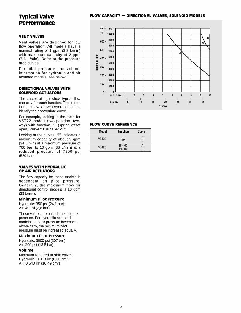
FLOW CAPACITY — DIRECTIONAL VALVES, SOLENOID MODELS
10000
9000
8000
7000
6000
5000
4000
3000
2000
1000
01 2 4 5 6 7 9 10
FLOW
35302520105
U.S. GPM
L/MIN.
PSI
3 8
15
PR
ES
SU
RE
700
600
500
400
300
200
100
0
BAR
A
B
C
VST22 PT BPC C
VST23 BT-PC APB-TC C
Model Function Curve
FLOW CURVE REFERENCE
Typical ValvePerformance
VENT VALVES
Vent valves are designed for lowflow operation. All models have anominal rating of 1 gpm (3,8 L/min)with maximum capacity of 2 gpm(7,6 L/min). Refer to the pressuredrop curves.
For pilot pressure and volumeinformation for hydraulic and airactuated models, see below.
DIRECTIONAL VALVES WITHSOLENOID ACTUATORS
The curves at right show typical flowcapacity for each function. The lettersin the “Flow Curve Reference” tableidentify the appropriate curve.
For example, looking in the table forVST22 models (two position, two-way) with function PT (spring offsetopen), curve “B” is called out.
Looking at the curves, “B” indicates amaximum capacity of about 9 gpm(34 L/min) at a maximum pressure of700 bar, to 10 gpm (38 L/min) at areduced pressure of 7500 psi (520 bar).

4
InstallationAnd Dimensions
DIMENSIONS
Dimensions throughout are shown ininches (millimeters in parentheses)and are nominal.
The valve body and overall dimen-sions vary depending upon the valveoperator (i.e., vent; two position, two-way; or two position, three-way).
Refer to the variable dimensiontables for dimensions specific toeach operator type.
HP03 VALVE MOUNTING
The mounting surface drawing showsthe minimum flush or raised surfacerequired for this special pattern.
As indicated, port “B” is required forModels VSTV and VST23; port “P” isrequired for VST22 and VST23.
Mounting face must be flat within0.0004 inch/4.0 inches (0,010mm/102 mm) with a surface finish of32 microinch (0,80 µm) AA.
Port o-rings are included with allvalves. Mounting bolts must beordered separately; .250-20 UNCThreaded x 2.00 inch (50,8 mm),Grade 8 or better; four required.Recommended mounting torque is12 lb• ft (16 N • m) maximum.
.16 (4,1) X .16 (4,1) DEEP MINIMUMLOCATING PIN HOLE
.0004/4.0(,010/102)
32(,80)
1.75(44,4)
1.30(33,0)
1.594(40,49)
2.00(50,8)
.19(4,8)
.25(6,4)
.625(15,88)
1.250(31,75)
.844(21,44)
.250-20 U.N.C.–2B THREADED
.43 (10,9) DEEP MINIMUM,4 MOUNTING HOLES
P
T
.468(11,89)
.468(11,89)
.234 (5,94), P PORT(MODELS VST22 AND VST23)
.250 (6,35), T PORT(ALL MODELS)
.234 (5,94), B PORT(MODELS VSTV AND VST23)
B
1.213(30,81)
Minimum Mounting Surface, Special HP03 Pattern
700
600
500
400
300
200
100
01 2 4 5 6 7 9 10
PR
ES
SU
RE
FLOW
35302520105
U.S. GPM
L/MIN.
50
40
30
20
10
0
A
B
CD
E
F
PSIBAR
3 8
15
Determining Valve Efficiency
PRESSURE DROP
The curves at right indicate pressuredrop for all VST valves.
These curves show resistance toflow for specific models, function andflow paths. The “Flow CurveReference” table identif ies theproper curve.
Maximum flow capacity depends onvalve operation, function and otherapplication factors. Refer to flowcapacity curves on page 3.
For example, looking in the table forVST23 models (two position, three-way) with function BT-PC (spring-offset B→T, P closed), curve “C” iscalled out for flow path B→T.
Looking at the curves, “C” indicatesa drop of about 190 psi (13 bar) at 5 gpm (19 L/min).
PRESSURE DROP (∆P)
VSTV NO ANC A
VST22 PT EPC F
BT-PCFlow Path B→T: C
VST23 Flow Path P→B: B
PB-TCFlow Path P→B: DFlow Path B→T: F
Model Function Curve
FLOW CURVE REFERENCE
5
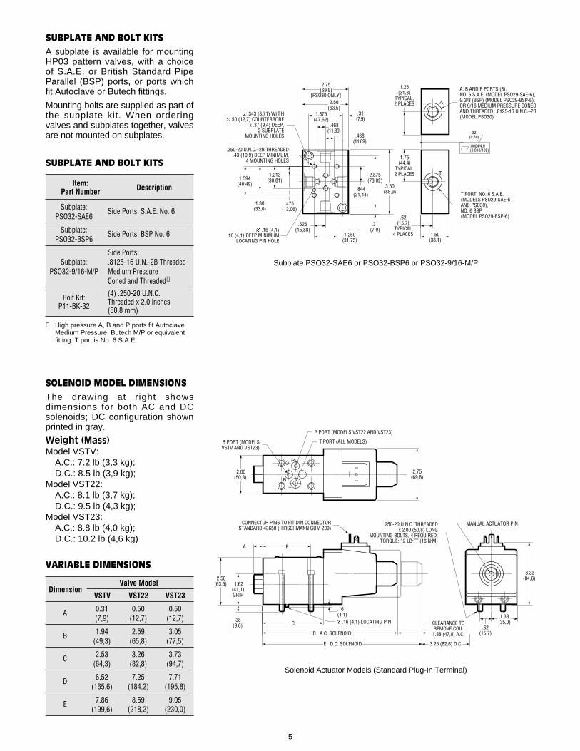
Subplate PSO32-SAE6 or PSO32-BSP6 or PSO32-9/16-M/P
SUBPLATE AND BOLT KITS
A subplate is available for mountingHP03 pattern valves, with a choiceof S.A.E. or British Standard PipeParallel (BSP) ports, or ports whichfit Autoclave or Butech fittings.
Mounting bolts are supplied as part ofthe subplate kit. When orderingvalves and subplates together, valvesare not mounted on subplates.
T
A
.62(15,7)
TYPICAL4 PLACES 1.50
(38,1)
1.75(44,4)
TYPICAL.2 PLACES
1.25(31,8)
TYPICAL,2 PLACES
T PORT, NO. 6 S.A.E.(MODELS PSO29-SAE-6AND PSO30),NO. 6 BSP(MODEL PSO29-BSP-6)
A, B AND P PORTS (3),NO. 6 S.A.E. (MODEL PSO29-SAE-6),G 3/8 (BSP) (MODEL PSO29-BSP-6),OR 9/16 MEDIUM PRESSURE CONEDAND THREADED, .8125-16 U.N.C.–2B(MODEL PSO30)
.16 (4,1).16 (4,1) DEEP MINIMUM
LOCATING PIN HOLE
.250-20 U.N.C.–2B THREADED.43 (10,9) DEEP MINIMUM,
4 MOUNTING HOLES
.625(15,88)
1.250(31,75)
.468(11,89)
1.875(47,62)
2.50(63,5)
.468(11,89)
.31(7,9)
.475(12,06)
1.213(30,81)
1.30(33,0)
1.594(40,49)
.844(21,44)
2.875(73,02)
3.50(88,9)
.31(7,9)
.343 (8,71) WI T H.50 (12,7) COUNTERBORE
x .37 (9,4) DEEP, 2 SUBPLATE
MOUNTING HOLES
2.75(69,8)
[PSO30 ONLY]
.0004/4.0(0,010/102)
32(0,80)
Subplate: Side Ports, S.A.E. No. 6PSO32-SAE6
Subplate: Side Ports, BSP No. 6PSO32-BSP6
Side Ports, Subplate: .8125-16 U.N.-2B Threaded
PSO32-9/16-M/P Medium PressureConed and Threaded➀
Bolt Kit: (4) .250-20 U.N.C.
P11-BK-32 Threaded x 2.0 inches (50,8 mm)
➀ High pressure A, B and P ports fit Autoclave Medium Pressure, Butech M/P or equivalent fitting. T port is No. 6 S.A.E.
DescriptionItem:Part Number
SUBPLATE AND BOLT KITS
SOLENOID MODEL DIMENSIONS
The drawing at r ight showsdimensions for both AC and DCsolenoids; DC configuration shownprinted in gray.
Weight (Mass)Model VSTV:
A.C.: 7.2 lb (3,3 kg);D.C.: 8.5 lb (3,9 kg);
Model VST22:A.C.: 8.1 lb (3,7 kg);D.C.: 9.5 lb (4,3 kg);
Model VST23:A.C.: 8.8 lb (4,0 kg);D.C.: 10.2 lb (4,6 kg)
.
.38(9,6) .62
(15,7)
.16(4,1) 1.38
(35,0)
2.50(63,5)
A B
CONNECTOR PINS TO FIT DIN CONNECTOR STANDARD 43650 (HIRSCHMANN GDM 209)
C
D A.C. SOLENOID
E D.C. SOLENOID 3.25 (82,6) D.C.
CLEARANCE TO REMOVE COIL1.88 (47,8) A.C.
MANUAL ACTUATOR PIN
3.33(84,6)
.16 (4,1) LOCATING PIN
2.00(50,8)
2.75(69,8)
1.62(41,1)GRIP
P
T
P PORT (MODELS VST22 AND VST23)
T PORT (ALL MODELS)B PORT (MODELSVSTV AND VST23)
B
.250-20 U.N.C. THREADEDx 2.00 (50,8) LONG
MOUNTING BOLTS, 4 REQUIRED;TORQUE: 12 LB•FT (16 N•M)
Solenoid Actuator Models (Standard Plug-In Terminal)
A 0.31 0.50 0.50(7,9) (12,7) (12,7)
B 1.94 2.59 3.05(49,3) (65,8) (77,5)
C 2.53 3.26 3.73(64,3) (82,8) (94,7)
D 6.52 7.25 7.71(165,6) (184,2) (195,8)
E 7.86 8.59 9.05(199,6) (218,2) (230,0)
DimensionValve Model
VSTV VST22 VST23
VARIABLE DIMENSIONS

.38(9,6)
.16(4,1)
.
2.50(63,5)
A B
C
D
CLEARANCE TOREMOVE ACTUATOR.44 (11,2)
1.62(41,1)GRIP
.250-20 U.N.C. THREADED x 2.00 (50,8)LONG MOUNTING BOLTS, 4 REQUIRED;TORQUE: 12 LB•FT (16 N•M)
2.56(65,0)
.16 (4,1) LOCATING PIN
1.88 (47,8) HEX
PILOT PORTNO. 6 S.A.E.
2.75(69,8)
.62(15,7)
1.38(35,0)
1.66(42,2)
Air Actuated Models (“A” Actuator Option)
AIR PILOTED MODELS
Weight (Mass)Model VSTV: 7.0 lb (3,2 kg);Model VST22: 7.9 lb (3,6 kg);Model VST23: 8.6 lb (3,9 kg)
DimensionValve Model
VSTV VST22 VST23
VARIABLE DIMENSIONS
2.75(69,8)
.62(15,7)
1.38(35,0)
1.66(42,2)
.38(9,6)
.16(4,1)
.
2.50(63,5)
A B
C
D
CLEARANCE TOREMOVE ACTUATOR.44 (11,2)
1.62(41,1)GRIP
.250-20 U.N.C. THREADED x 2.00 (50,8)LONG MOUNTING BOLTS, 4 REQUIRED;TORQUE: 12 LB•FT (16 N•M)
2.03(51,6)
.16 (4,1) LOCATING PIN
1.25 (31,8) HEX
PILOT PORTNO. 6 S.A.E.
Hydraulic Actuated Models (“H” Actuator Option)
HYDRAULIC PILOTED MODELS
Weight (Mass)Model VSTV: 6.2 lb (2,8 kg);Model VST22: 7.1 lb (3,2 kg);Model VST23: 7.8 lb (3,5 kg)
DimensionValve Model
VSTV VST22 VST23
VARIABLE DIMENSIONS
EXPLOSION PROOF SOLENOIDS
Weight (Mass)Model VSTV: 14.8 lb (6,7 kg);Model VST22: 15.7 lb (7,1 kg);Model VST23: 16.4 lb (7,4 kg)
6
.38(9,6)
.16(4,1)
2.50(63,5)
A B
C
D
.16 (4,1) LOCATING PIN
1.62(41,1)GRIP
3.87 (98,3)
CLEARANCE TO REMOVE COIL
LEADWIRES (2) TYPICAL,#18 AWG APPROXIMATELY18 (457) LONG
GROUNDWIRE, #18 AWG (GREEN INSULATION) APPROXIMATELY 18 INCHES (457) LONG
1/2-14 N.P.T. STANDARD ELECTRICAL ENTRY, 360° ROTATABLE, WITH BOTTOM OUTLET SUBPLATE
1.66(42,2)
NOTE: KEEP AIR GAP BETWEEN SOLENOID AND VALVE BODY CLEAN
3.62(92,0)
4.74(120,4)
SOLENOID POSITION LIMITWITH SIDE OUTLET SUBPLATEOR SANDWICH VALVE
45°
MANUAL OVERRIDE PIN
.62(15,7)
1.38(35,0)
4.19(106,4)
.250-20 U.N.C. THREADED x 2.00 (50,8)LONG MOUNTING BOLTS, 4 REQUIRED;TORQUE: 12 LB•FT (16 N•M)
A 0.31 0.50 0.50(7,9) (12,7) (12,7)
B 1.94 2.59 3.05(49,3) (65,8) (77,5)
C 2.53 3.26 3.73(64,3) (82,8) (94,7)
D 5.56 6.29 6.76(141,2) (159,8) (171,7)
A 0.31 0.50 0.50(7,9) (12,7) (12,7)
B 1.94 2.59 3.05(49,3) (65,8) (77,5)
C 2.53 3.26 3.73(64,3) (82,8) (94,7)
D 6.09 6.82 7,29(154,7) (173,2) (185,2)
DimensionValve Model
VSTV VST22 VST23
VARIABLE DIMENSIONS
A 0.31 0.50 0.50(7,9) (12,7) (12,7)
B 1.94 2.59 3.05(49,3) (65,8) (77,5)
C 2.53 3.26 3.73(64,3) (82,8) (94,7)
D 8.27 9.00 9.47(210,1) (228,6) (240,5) Explosion Proof Solenoid Models (EP Actuator Option)

7
Typical Model Code
VST 23 BT-PC — HP03 — 115HA — HT — N — 1 0
Valve Type
Subplate MountedSeated Valve
Operation
V — Vent22 — Two Position, Two-Way23 — Two Position, Three-Way
Mounting Interface
HP03 — High Pressure, Special MountingPattern
Electric Options(Plug-In Terminal Only)
HT — High Pressure Tank Port, Maximum:3000 psi (210 bar) dynamic, 5000 psi (350 bar) static
M — Hand Actuated Manual Override
Seals
No Code — Viton (Standard)N — Buna-NE — EPR
Actuator
PLUG-IN TERMINAL SOLENOIDS:➀
115HA — Dual Frequency, 115/60, 110/50230HA — Dual Frequency, 230/60, 220/5012HD — Direct Current, 12 Volts24HD — Direct Current, 24 Volts
EXPLOSION PROOF:24EP — Explosion Proof Solenoids,
Direct Current, 24 Volts115EP — Explosion Proof Solenoids, 115/60110EP — Explosion Proof Solenoids, 110/50220EP — Explosion Proof Solenoids, 220/50
HYDRAULIC:H — Hydraulic Actuator
AIR:A — Air Actuator
➀ Fits DIN Connector Standard 43650 (Hirschmann GDM 209). For other voltages consult the Dynex sales department.
B
T
B
T
P
P
T
T
B
T
B
T
P
P
Functions
Vent Valve:➀
NO — Spring Offset Open
NC — Spring Offset Closed
Two Position, Two-Way:➀
PT — Spring Offset Open
PC — Spring Offset Closed
Two Position, Three-Way:
BT-PC — Spring Offset B→T, P Closed
PB-TC — Spring Offset P→B, T Closed
➀ As shown in the schematic, one port on these valves must be connected to tank. For maximum tank port pressures, refer toBulletin VES.VST.
DesignNumber
ModificationNumber