engineering specification and design guidancetrapezoidal cross section with 1 in 2 side slopes and...
TRANSCRIPT

WILTS & BERKS CANAL TRUST PATRON: HRH THE DUCHESS OF CORNWALL
RESTORING IN PARTNERSHIP THE WILTS & BERKS CANAL THROUGH WILTSHIRE, SWINDON AND OXFORDSHIRE
Copyright © Wilts and Berks Canal Trust 2018 Wilts & Berks Canal Trust: A Non-Profit-Distributing Company Limited by Guarantee. Registered in England and Wales No. 2267719 Registered Address: Dauntsey Lock Canal Centre Chippenham SN15 4HD Registered Charity No: 299595 Telephone: 0845 625 1977 E-mail: [email protected] Web Site: www.wbct.org.uk
1
Engineering Specification and Design Guidance
Version 1.0
Approved by: Andrew Matters
Head of Engineering
June 2018

WILTS & BERKS CANAL TRUST Engineering Specification and Design Guidance
2
Contents Background ............................................................................................................................................. 3
Engineering Specification .................................................................................................................. 4 Introduction............................................................................................................................................. 4 Restoration Standards ......................................................................................................................... 4 Dimensional Criteria ............................................................................................................................. 4 Horizontal Alignment .......................................................................................................................... 12 Design Life for Structures ................................................................................................................. 12 Water tightness .................................................................................................................................... 12 Lock Furniture....................................................................................................................................... 12 Towpath Construction ........................................................................................................................ 13 Canal-side Furniture ........................................................................................................................... 13 Edging and Planting ............................................................................................................................ 13
Design Guidance .................................................................................................................................. 15 Earthworks and Geology ................................................................................................................... 15
General ............................................................................................................................................... 15 Embankment and Materials .......................................................................................................... 15 Cuttings .............................................................................................................................................. 16
Structures .............................................................................................................................................. 17 Bricks ................................................................................................................................................... 17 Buildings ............................................................................................................................................. 17 Bridges ................................................................................................................................................ 17
Pound Levels, Locks and Back Pumping ....................................................................................... 15 Pound Level and Lock Lifts ............................................................................................................ 15 Lock Back-pumping & Water Supply .......................................................................................... 20 By-washes. ......................................................................................................................................... 20 Pumping intakes and outfalls. ...................................................................................................... 20
Freeboard ............................................................................................................................................... 21

WILTS & BERKS CANAL TRUST Engineering Specification and Design Guidance
3
Background In 1998 a comprehensive report was commissioned on the restoration of the Wilts & Berks Canal. Written by consultants Scott Wilson Kirkpatrick, Chapter 3 concentrated on the engineering specification and technical aspects of the canal. 20 years later it has been decided that the Wilts & Berks Canal Trust should produce an Engineering Specification based on this work. This document is based upon the original Scott Wilson work and is updated and amended where necessary. This document now supersedes the original report and any other subsequent specification. The application of the Specification in the first part of this document is mandatory for the design of all restoration work where it can be applied without affecting important heritage features and mandatory for new build unless a specific exemption is approved by the Chief Engineer. The second part of this document provides discussion and general advice to amplify the application of the Specification. Wilts & Berks Canal Trust will be pleased to review any designs for the canal prepared by other parties.

WILTS & BERKS CANAL TRUST Engineering Specification and Design Guidance
4
Engineering Specification Introduction This section provides the essential dimensional standards and other factors for the restoration and construction of the Wilts & Berks Canal. The objective is to ensure consistency and result in a waterway that is fit for purpose throughout its length. New works and restoration works shall comply with the requirements and standards of the Canal and River Trust except where deviation from them is essential for local or historical reasons. Refer also to drawings of standard details and WBCT adopted policies. Further mandatory standards for elements of the canal construction will be developed and applied. Restoration Standards The original dimensions of locks on the Wilts & Berks Canal, are reported in the Royal Commission on Canals and Waterways 1907. All locks were reported as having a length of 74'0" (22.555m); the majority were of width 7'2" (2.184m) with the widest at 7'6" (2.286m). Depth of water over the cill was reported as 4'0" (1.219m) between Swindon and Abingdon and generally 4'2" (1.270m) elsewhere, with a maximum of 4'8" (1.422m) at Chaddington Top (Summit) Lock. No original Wilts & Berks specifications have survived, so this work has originated a specification based on what empirically has been gleaned from surviving structures and standards for other narrow canals. Clearly all original dimensions would have been made in imperial units and the metric specification is generally a conversion from the original. Dimensional Criteria
Boat Maximum Size: Length 21.946m (72ft) Beam 2.134m (7ft) Draught 0.991m (3’ 3”)
Channel Size Standard (m) Minimum (m) Bed Width (trapezoidal section) 5.33 (or original) 4.27 Depth of water 1.5 (or original) 1.37 Freeboard 0.3 minimum Waterway cross sectional Area 13 sq. m 10sq m Width at locks (low) 2.2 or original Lock Length (cill to closed gates) 22.6 or original

WILTS & BERKS CANAL TRUST Engineering Specification and Design Guidance
5
Bridge hole width 2.7 2.4 Air draught over minimum 2m width 2.7 2.3 Water velocity 0.37m/s max
Other Criteria Towpath width (m) 3 2 Towpath headroom (pedestrians only) (m) 2.3 to 2.4 2.3 to 2.4 Towpath headroom (horse and rider) (m) 3.7 3.7 Water supply No restrictions unless 1in10 year drought
Where dimensions are converted to Metric units and rounded for convenience they should be rounded up. It is useful to set both standard and minimum dimensions to ensure that rigid adherence to desirable standards does not preclude cost effective solutions to overcoming major obstructions which might be achieved through a relaxation of standards. The IWA paper "Waterway Restoration" (Harrison, 1996) suggests that for new and rebuilt lengths of channel the bed width should be at least 2.5 times the beam of typical craft (i.e. 5.33m). This has been used to set the standard minimum bed width of 5.33m. Hence the standard trapezoidal channel 1.5m deep with 1:2 side slopes has an overall width of 11.33m and a cross-sectional area of 12.5m2. The channel size criteria in the table above are not self-consistent since applying the waterway cross-sectional areas above may result in greater bed width. A typical channel trapezoidal cross section with 1 in 2 side slopes and minimum water depth 1.37m, would require a bed width of only 4.56m to provide a minimum waterway area of 10sqm. This cross section yields a surface width of 10.04m and a navigable width of 6.04m at 1.0m draught. A cross-section with vertical banks would require a bed width of 7.30m for the same waterway area and depth. Applying the same calculation to the 13sqm standard waterway area and 1.5m standard depth yields a surface width of 11.67m and bed width 5.67m at 1 in 2 side slopes for a navigable width of 8.67m at 1.0m draught, or a width of 8.67m with vertical banks. Again this exceeds the standard bed width criterion. These desirable dimensions are adopted where space allows. Desirable and minimum criteria for winding holes - dimensions and frequency – will need to be set in due course. Water velocity will be an issue where navigation on existing watercourses is required. The desirable maximum velocity may be exceeded during times of flood. The freeboard requirement may be increased locally for water management or other reasons; refer to the guidance section. Towpath width and headroom requirements will be influenced by the need to accommodate cyclists and horse riders in some locations. The dimensions above are for a short tunnel for pedestrians only. Refer to Highways England guidance TD 36/93 for other users and long tunnels. The full headroom may not be achievable over the full
WILTS & BERKS CANAL TRUST Engineering Specification and Design Guidance
6
towpath width depending on the type of structure. Sections of the route which are intended to accommodate users other than pedestrians will need to be identified. It will be preferable, where practicable, to provide separate paths for cycle ways or bridleways to avoid conflicts between users.

WILTS & BERKS CANAL TRUST Engineering Specification and Design Guidance
5
Figure 1a – Standard dimensions of canal cross-section in embankment

WILTS & BERKS CANAL TRUST Engineering Specification and Design Guidance
6
Figure 1b – Standard dimensions of canal cross-section in cutting in clay

WILTS & BERKS CANAL TRUST Engineering Specification and Design Guidance
7
Figure 1c – Standard dimensions of canal cross-section in cutting in granular material

WILTS & BERKS CANAL TRUST Engineering Specification and Design Guidance
8
Figure 2 – Standard dimensions of rectangular canal cross-section
Typical canal rectangular cross-section

WILTS & BERKS CANAL TRUST Engineering Specification and Design Guidance
9
Figure 3 – Standard dimensions of Bridge Hole
Typical canal cross-section at Bridge Hole
WILTS & BERKS CANAL TRUST Engineering Specification and Design Guidance
10
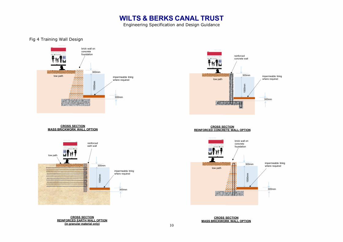
Fig 4 Training Wall Design
brick wall on concrete foundation
tow path
1500
mm
300mm
CROSS SECTIONMASS BRICKWORK WALL OPTION
impermeable lining where required
300mm
reinforced eath wall
tow path
1500
mm
300mm
CROSS SECTIONREINFORCED EARTH WALL OPTION
(in granular material only)
impermeable lining where required
300mm
reinforced concrete wall
tow path
1500
mm
300mm
CROSS SECTIONREINFORCED CONCRETE WALL OPTION
impermeable lining where required
300mm
brick wall on concrete foundation
tow path
1500
mm
300mm
CROSS SECTIONMASS BRICKWORK WALL OPTION
impermeable lining where required
300mm

WILTS & BERKS CANAL TRUST Engineering Specification and Design Guidance
11
Figure 5 Standard Lock Dimensions
23000mm4000mm 4000mm
B A
B A
PLAN
Max dropheight 3000mm
LONGITUDINAL SECTION

WILTS & BERKS CANAL TRUST Engineering Specification and Design Guidance
12
Figure 6 Standard Lock Dimensions (Continued)
Max dropheight 3000mm
1500
mm
9" brick wall with reinforced concrete backing
2475mm
CROSS SECTION BB
Dished invert to lock
1500
m
9" brick wall with reinforced concrete backing
2475mm
CROSS SECTION AA(lock gates not shown)
Dished invert to lock

WILTS & BERKS CANAL TRUST Engineering Specification and Design Guidance
12
Criteria for capacity and clearances for aqueducts over or culverts under significant watercourses will need to be set in due course in consultation with the Environment Agency. In general there will be a need to ensure free headroom in the culverts under normal conditions although a degree of operation in siphon mode with consequent backing up of water may be acceptable for extreme flood.
Horizontal Alignment The dimensions given above assume a relatively straight horizontal alignment. At tight bends and junctions additional width will be required to allow longer craft to turn and pass other craft. The desirable standard is for two 22m narrowboats to be able to pass with a clearance of half a boat width between them. As a minimum, a single 22m narrowboat must be able to navigate with sufficient clearance on both sides. Consideration must be given to the swept circle of a turning craft and the forward visibility for the steersman at the rear. Design Life for Structures A design life of 120 years will be specified for concrete, steel and masonry structures. Hardwood timber design life is typically 35 to 40 years. Steel surfaces need to be repainted every 25 to 30 years. Bridges shall be ‘integral’ wherever possible to eliminate the maintenance requirements associated with bearings and movement joints. Water tightness Water resources to maintain navigation in the canal are difficult to find and exploit. All construction and restoration should seek to minimise losses including seepage. Where construction is in natural clays it may be sufficient to simply leave the bed in the natural state but the competency of the natural material should be proven prior to construction. Lining the canal up to design water level to minimise losses may be undertaken using artificial lining materials such as bentonite or butyl sheeting. Traditional clay puddle is an expensive solution difficult to achieve with modern machinery. Sheet piling is not inherently watertight and requires treatment by placing puddle clay behind the piles or applying a sealing material to one face of the piles. Particular attention should be paid the detailing of changes of construction such as at junction of piles and a clay or lined bed and adjacent to structures where leakage paths may develop. Lock Furniture
• Ladders. These will be incorporated in all the reconstructed locks, following CRT practice.
• Lock Gates. These will be standardised using the modular steel type in
accordance with the WBCT policy on Lock Gates.
• Paddle Gear. The traditional W&B type is unique and would be very expensive to recreate. Alternative options will be considered in accordance with the WBCT policy on paddle gear.

WILTS & BERKS CANAL TRUST Engineering Specification and Design Guidance
13
Towpath Construction The towpath will be designed to allow multiple use wherever possible. Where cycling is expected the design guide width is 3.0m minimum wherever possible and wider where heavy usage is expected. Surfacing will be appropriate to location and will range from fully sealed ‘tarmac’ in urban areas to rolled stone/dust in other high use areas or heritage style block paving to the surface in rural locations.
Canal-side Furniture
• Bollards. Where used for waiting areas and lock operation it is recommended that consideration is given to installing mushroom type bollards to prevent ropes slipping during boating operation but which are easy to release.
• Mooring Rings. These are to be used on designated mooring areas as they are
more difficult to cast a boat adrift from than bollards.
• Seating. Type to be determined according to location and usage
• Stiles. To be avoided on the towpath because of the restriction to the less abled user.
• Gates (pedestrian and vehicular). Careful design is required to ensure access for
the less abled by wheelchair or scooter. A staggered barrier arrangement may be needed to permit free flow of pedestrians, while deterring misuse of the towpath by motorcycles and quad bikes.
• Path gradients. Steps should be avoided and path gradients should meet the
disability access guidance suited to the location.
• Safety Railing. Safety railing is not normally provided at the waterside but should be considered where unusual conditions or risks exist, e.g. at ramps and entrance points to the towpath.
• Information Boards and Notices.
• Life Saving Equipment.
Edging and Planting As a general principle the canal will be designed in such a way as to encourage maximum biodiversity. Edges. The towpath edge will generally be at a depth to allow boat access /mooring. This edge will need to be protected from erosion and ‘soft protection will generally be preferred to hard engineering piling or walls (other than in appropriate locations). Planting.

WILTS & BERKS CANAL TRUST Engineering Specification and Design Guidance
14
• General. The off-side, which will in general be a sloping bank, can be planted using coir rolls laid at the top of the bank. Natural vegetation can be allowed to colonise over coir rolls or brushwood edging. Random stone edging may be applied in areas exposed to erosion.
• Grass. Generally there will be a vegetation strip between the canal and the
towpath which will be planted and maintained to provide a margin of safety for towpath users.
• Hedges. Wherever possible the original canal hedge will be retained and
maintained. The aim will be to have a canal with hedgerow defining the outer extent of the canal corridor.
• Trees. Where new planting takes place due note of root spread should be taken
into account to avoid compromising the canal’s water retaining and other structural integrity. In general there will be no tree planting in the vegetation strip between the canal and towpath
• In-water vegetation. Planting in the water edge is not normally desirable. Reeds
and other plants will rapidly colonise the edge and will need continual maintenance to permit navigation.

WILTS & BERKS CANAL TRUST Engineering Specification and Design Guidance
15
Design Guidance Earthworks and Geology General The earthworks required in the restoration of the Canal involve in the main only small embankments and cuttings but a few are embankments are up to 3.5m above existing ground level and cuttings to a maximum of 6m. In all cases the initial operation will be the stripping of topsoil from all areas where new earthworks are required; this will be stockpiled for re-use as far as possible on the completed earthworks. Potential problems can arise with disposal of surplus material from the canal restoration, including contaminated land through illicit dumping. It is intended that as far as possible all suitable material arising from the works is put to beneficial re-use, including cosmetic landscaping, and thus avoiding disposal costs. This is also necessary to avoid the landfill tax. The use of materials arising from the works and their use in embankments, together with the stability of cut slopes, is discussed below. However, it should be noted that geotechnical design, particularly of cut slopes, will depend upon the precise nature of the soils as determined by site investigation. The outcrop geology for the original W&B Canal is summarised in this table, taken from the 1998 Scott Wilson Kirkpatrick report:
[Map of geology along of route of canal to be developed] Embankment and Materials It is likely that the only materials that will prove unsuitable for use in earthworks will be soft clays of the alluvium deposits. Otherwise, all materials should be useable although different techniques may have to be employed in their placement. Sands and gravels can be easy to place and compact; relatively light plant can be used depending upon the layer thickness adopted during placement. Some problems have been encountered during earthworks in the Lower Greensand, as the upper weathered layers of

WILTS & BERKS CANAL TRUST Engineering Specification and Design Guidance
16
this material can be clayey and difficult to handle. However, the use of lighter plant eases these problems, so it is not anticipated that major difficulties will be encountered on this type of project. In view of their permeability, a lining will be required for new embankments formed of sands and gravels. The Corallian deposits can, depending on their degree of weathering, be excavated as large individual blocks. This does not necessarily produce a difficulty providing such material is used on higher embankments. Nevertheless, some breaking down of such material, if encountered, would probably be worthwhile. The main difficulty envisaged lies with the stiff clays of the Gault, Kimmeridge and Oxford Clays. These tend to be excavated, and therefore deposited, as large individual "lumps" unless heavy compaction plant is used (including use of sheepsfoot type rollers). The use of lighter plant leads to a more open textured compacted material, which not only is more permeable, and hence requires a liner, but can soften with time resulting in settlement. The latter can be accommodated by an increase in freeboard. Cuttings It is unlikely that cuttings will be required in the flat topography where alluvial deposits are to be encountered. Cuttings into Lower Greensand deposits and sands and gravels may require some stability analysis, but slopes of 1(v):2(h) can be used for preliminary design. The main concern with these materials is the early placement of topsoil to prevent erosion. Lining will be required. Cuttings into the Gault, Kimmeridge and Oxford Clays will require more consideration. There has been considerable recent study of cuttings formed in these materials, following a series of slope failures sometime (up to 20 years) after construction. This has been attributed to equalisation of the negative pore water pressures developed within the clays as a result of the removal of material. The solution that has been adopted for motorway cuttings is to form relatively flat slopes, between 1(v):4 or 5(h); this may be impracticable for this project. Possible solutions may be provision of retaining walls at the toe of cuttings to reduce soil slopes, or the use of bio-engineering to minimise restoration of pore water pressures. Temporary or permanent provision of drainage for ground water may be required. This aspect requires careful design. Where a waiting wall is constructed on the offside as part of a cutting and a towpath is present on the other side there will be a ledge fitted with bollards. The ledge will be paved and at least 1000mm wide at a freeboard of 300mm.

WILTS & BERKS CANAL TRUST Engineering Specification and Design Guidance
17
Structures Bricks Bricks will be selected and used in accordance with the approved WBCT Bricks policy. Buildings New buildings will be designed and built using modern techniques such as timber framing but with an external appearance consistent with the heritage aspects of the canal. Existing buildings will be restored where possible to the original design. Bridges There are three principal factors which influence bridge type selection; function, form and cost.
Function In consideration of the function of a bridge, the end use of the bridge should be examined in detail. For the purpose of this work, there are four principal crossing types:
• primary and secondary public roads • private access roads and tracks • railway lines • watercourses
Public Roads These vary from motorways with high volumes of traffic, particularly at peak hours, to quiet country lanes with little or no traffic during a single day. Similarly the private access roads or tracks may have little or no traffic. Both public and private roads carry vehicles of varying size and weights and, since 1999, public road bridges have been required to carry vehicles with 40T gross vehicles, or 11.5 tonne axles for short spans. Full compliance with Eurocode BS EN 1991-2:2003 and the National Annexe is required for new construction. Private Roads These generally carry lighter vehicles; this does not mean however that access for larger vehicles is not required. A private access road to a farm, for example, may on occasions carry heavy vehicles (farm machinery or deliveries of bulk animal feed). A further example may be a private access track used very little (once or twice a week) by a farmer driving an off-road vehicle to visit a field. It is therefore necessary to carry out a detailed study of the types of vehicles which could possibly use a bridge before the type of bridge can be selected. All private bridges are to be suitable to carry 40 tonne vehicles. Guidance on dimensions for agricultural crossings is given in ‘Report of the Study Group on Dimensions of Agricultural Bridges and Underpasses’ DTp, MAFF,

WILTS & BERKS CANAL TRUST Engineering Specification and Design Guidance
18
1985. Railway Lines The London to Bristol railway line crosses the route of the Canal at four locations and the Swindon to Stroud railway line crosses the Canal at one location; both railways are in continual use. The loading from rail vehicles is greater than that arising from road vehicles and this has an impact on bridge type selection. Over many years British Rail developed ‘standard' bridge designs, with both steelwork and reinforced concrete decks. These standard designs are relatively cost effective and easy to construct and a major benefit of adopting such a design is that the gaining of approval from the infrastructure owner (Network Rail)) should be straightforward. It should be noted however that structure jacking (thrust boring) of reinforced concrete boxes under railway lines has been successfully completed at a number of locations on the rail network. All railway works have to be accomplished within limited duration possessions, the maximum available is typically 72 hours. For deck type construction, this usually requires abutments to be pre-installed within thrust bored tunnels in advance of the possession.
Form The second major consideration is the form of the bridge. Form is related to function, indeed many designers believe that ‘form follows function' and that simple functional structures are the most aesthetically pleasing to the eye. Visual impact and aesthetics are major considerations, together with the appropriateness for a particular location. For example, a footbridge constructed in timber would be more in keeping within a rural setting than a similar structure formed in concrete. Aesthetics is an emotive subject and individual tastes vary considerably. Therefore in determining bridge aesthetics there should be a high degree of involvement from all the interested parties and local residents (where appropriate). The structural form of the bridges could be chosen in such a way so as to project an image for the Canal and where appropriate traditional canal architecture could be replicated to produce a "family" of bridges. It is expected that brick facades will be utilised to dress basic concrete structures. The bridge type should also be selected to suit the expected ground conditions and its impact on the environment and any existing infrastructure. Consideration should also be given to the method of demolition when the structure has reached the end of its economic life. Structural form has an impact on buildability. Placing horizontal and vertical concrete surfaces is easier to form than inclined surfaces or arches. Forming concrete within a factory (pre--casting) is easier than undertaking the work on site.
Cost Cost may be considered to be the most important factor in bridge type selection. It is essential to consider the whole life cost for a particular bridge type and not merely the construction cost. The cost of construction does however play a major part in the selection process. Material selection (steel, concrete, timber, etc.) and the cost of protection and maintenance of the materials should be considered.
WILTS & BERKS CANAL TRUST Engineering Specification and Design Guidance
19
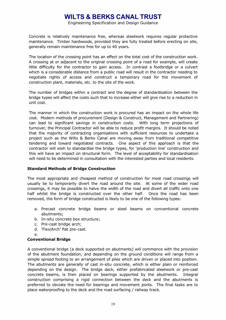
Concrete is relatively maintenance free, whereas steelwork requires regular protective maintenance. Timber hardwoods, provided they are fully treated before erecting on site, generally remain maintenance free for up to 40 years. The location of the crossing point has an effect on the total cost of the construction work. A crossing at or adjacent to the original crossing point of a road for example, will create little difficulty for the contractor to gain access. In contrast a footbridge or a culvert which is a considerable distance from a public road will result in the contractor needing to negotiate rights of access and construct a temporary road for the movement of construction plant, materials, etc. to the site of the work. The number of bridges within a contract and the degree of standardisation between the bridge types will affect the costs such that to increase either will give rise to a reduction in unit cost. The manner in which the construction work is procured has an impact on the whole life cost. Modern methods of procurement (Design & Construct, Management and Partnering) can lead to significant savings in construction costs. With long term projections of turnover, the Principal Contractor will be able to reduce profit margins. It should be noted that the majority of contracting organisations with sufficient resources to undertake a project such as the Wilts & Berks Canal are moving away from traditional competitive tendering and toward negotiated contracts. One aspect of this approach is that the contractor will wish to standardise the bridge types, for ‘production line' construction and this will have an impact on structural form. The level of acceptability for standardisation will need to be determined in consultation with the interested parties and local residents.
Standard Methods of Bridge Construction The most appropriate and cheapest method of construction for most road crossings will usually be to temporarily divert the road around the site. At some of the wider road crossings, it may be possible to halve the width of the road and divert all traffic onto one half whilst the bridge is constructed over the other half. Once the road has been removed, the form of bridge constructed is likely to be one of the following types:
a. Precast concrete bridge beams or steel beams on conventional concrete
abutments; b. In-situ concrete box structure; c. Pre-cast bridge arch; d. ‘FlexiArch’ flat pre-cast. e.
Conventional Bridge A conventional bridge (a deck supported on abutments) will commence with the provision of the abutment foundation, and depending on the ground conditions will range from a simple spread footing to an arrangement of piles which are driven or placed into position. The abutments are generally of cast in-situ concrete, which is either plain or reinforced depending on the design. The bridge deck, either prefabricated steelwork or pre-cast concrete beams, is then placed on bearings supported by the abutments. Integral construction comprising a rigid connection between the deck and the abutments is preferred to obviate the need for bearings and movement joints. The final tasks are to place waterproofing to the deck and the road surfacing / railway track.
WILTS & BERKS CANAL TRUST Engineering Specification and Design Guidance
20
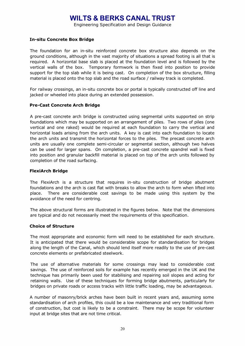
In-situ Concrete Box Bridge The foundation for an in-situ reinforced concrete box structure also depends on the ground conditions, although in the vast majority of situations a spread footing is all that is required. A horizontal base slab is placed at the foundation level and is followed by the vertical walls of the box. Temporary formwork is then fixed into position to provide support for the top slab while it is being cast. On completion of the box structure, filling material is placed onto the top slab and the road surface / railway track is completed. For railway crossings, an in-situ concrete box or portal is typically constructed off line and jacked or wheeled into place during an extended possession.
Pre-Cast Concrete Arch Bridge A pre-cast concrete arch bridge is constructed using segmental units supported on strip foundations which may be supported on an arrangement of piles. Two rows of piles (one vertical and one raked) would be required at each foundation to carry the vertical and horizontal loads arising from the arch units. A key is cast into each foundation to locate the arch units and transmit the horizontal forces to the piles. The precast concrete arch units are usually one complete semi-circular or segmental section, although two halves can be used for larger spans. On completion, a pre-cast concrete spandrel wall is fixed into position and granular backfill material is placed on top of the arch units followed by completion of the road surfacing.
FlexiArch Bridge The FlexiArch is a structure that requires in-situ construction of bridge abutment foundations and the arch is cast flat with breaks to allow the arch to form when lifted into place. There are considerable cost savings to be made using this system by the avoidance of the need for centring. The above structural forms are illustrated in the figures below. Note that the dimensions are typical and do not necessarily meet the requirements of this specification. Choice of Structure The most appropriate and economic form will need to be established for each structure. It is anticipated that there would be considerable scope for standardisation for bridges along the length of the Canal, which should lend itself more readily to the use of pre-cast concrete elements or prefabricated steelwork. The use of alternative materials for some crossings may lead to considerable cost savings. The use of reinforced soils for example has recently emerged in the UK and the technique has primarily been used for stabilising and repairing soil slopes and acting for retaining walls. Use of these techniques for forming bridge abutments, particularly for bridges on private roads or access tracks with little traffic loading, may be advantageous. A number of masonry/brick arches have been built in recent years and, assuming some standardisation of arch profiles, this could be a low maintenance and very traditional form of construction, but cost is likely to be a constraint. There may be scope for volunteer input at bridge sites that are not time critical.

WILTS & BERKS CANAL TRUST Engineering Specification and Design Guidance
21
Where locks occur immediately adjacent to crossings (and in planning the location of proposed new locks this has often been a consideration), there is an opportunity to combine the bridge and lock structures, the bridge becoming a ‘tail bridge' below the bottom gate. Additional Factors for Railway Crossings In the case of a crossing under main railway lines (of which there are several on the WBCT Preferred route), the minimum requirement would be for 300mm of ballast beneath the track. A rectangular culvert section is likely to be preferred to a circular one. Runoff slabs are commonly required. A temporary speed restriction would be required to install the structure and for a short period of time thereafter, for which a payment would be required. Wherever possible for new construction, the bridge or box carrying the railway should have minimised or no skew, since the subsequent settlement of backfill on the approaches can lead to track twist and derailment. For each railway line, Network Rail produces an annual private publication known as ‘The Rules of the Route' which details the no-train periods in which normal weekday and weekend possessions of the line may be available. Also included in the publication are abnormal possessions which have been allocated to major items of work, such as bridge reconstruction or permanent way renewal. With the agreement of Network Rail, it may be possible to utilise suitable abnormal possessions for installing a structure across or under the railway. Under the terms of the agreement required for crossing the railway, the ownership of the structure will be vested in Network Rail. Network Rail would wish to recover maintenance costs on an "as and when" basis and undertake to give a minimum of two years notice of the requirement for major maintenance or repair. Network Rail would also require an authority for the expenditure of £5000 per annum for day-to-day maintenance. Alternative Crossing Methods There are a number of crossings of major roads and railway lines along the line of the Canal for which the standard methods mentioned above would not be appropriate. The following three techniques would be available to create openings at these crossings without diverting the road/railway and with little disruption to existing users. Structure Jacking Structure jacking is a technique of installing a circular or rectangular concrete tunnel-like structure underground by thrusting horizontally a single or several pre-fabricated elements (usually boxes), from a prepared pit. A shield is provided at the front to cut the ground and support the exposed face whilst spoil is removed from the face by mining and passed back through the box. The structure is thrust forward by means of hydraulic jacks bearing against a temporary thrust wall or jacking base. To reduce the effect of the moving structure on the overlying road / railway an anti-drag system can be introduced at the top and bottom of the box to reduce friction. Structure jacking is essentially a soft ground tunnelling technique and its success is dependent on an adequate foreknowledge of the ground conditions to be expected along

WILTS & BERKS CANAL TRUST Engineering Specification and Design Guidance
22
the proposed drive. The ideal ground conditions for structure jacking are stiff clay, clay or dense fine sands with apparent cohesion as these require the minimum of support and can be readily mined. A small amount of settlement of the road/railway above will inevitably arise from this method, but can be controlled by careful design of tunnelling shield and interaction between excavation and progress of shield. If a structure has very little cover, then a grillage of steel beams may be required to maintain the vertical alignment of the road/railway.

WILTS & BERKS CANAL TRUST Engineering Specification and Design Guidance
12
Fig 7 Pre-cast concrete structure

WILTS & BERKS CANAL TRUST Engineering Specification and Design Guidance
13
Fig 8 Concrete Box construction

WILTS & BERKS CANAL TRUST Engineering Specification and Design Guidance
14
Fig 9 Bridges with unrestricted canal corridor
2.7m
min
2.3m
min
*
1.5m
0.3m
5.33m 3.6m 5.0mberm
3.0m berm
3.6m
1
1 1
1
22
4 4
1 110 10
1133
clear span ≈20m
Typical canal cross-sectionCanal in cut at cycleway bridges
* Clearance under bridge deck needs to be 3.7m for horse and rider
Original Ground Level
1.5m

WILTS & BERKS CANAL TRUST Engineering Specification and Design Guidance
15
2.7m
min
2.3m
min
*
0.3m
5.33m
5.0mberm
3.0mberm
4.0m
1 110 10
clear span ≈20m normal to canal alignment
Typical canal cross-sectionCanal in fill at road bridge * Clearance under bridge deck needs
to be 3.7m for horse and rider
1.5m
3.51
21 1
2
13.5
4.0m7.0m
Original Ground Level
7.0m
2.0m
4.5m

WILTS & BERKS CANAL TRUST Engineering Specification and Design Guidance
16
Fig 10 Arch Construction

WILTS & BERKS CANAL TRUST Engineering Specification and Design Guidance
17
Fig 11 Flexi-arch Construction

WILTS & BERKS CANAL TRUST Engineering Specification and Design Guidance
12
It should be noted that the jacking of box structures, particularly under railway lines where the limitations on the variation of vertical alignment are more stringent than roads, has been completed successfully on a number of occasions and that there are a number of contractors with the expertise to carry out such work. The pre-fabricated units are most economically made of reinforced concrete as this material provides a rigid unit capable of withstanding the jacking forces in addition to earth pressure and live loads without undue distortion. Steerage of the unit is achieved primarily by adjusting the inclination of the shield or lead unit. The jacking work is normally carried out on a continuous round-the-clock basis both to minimise the installation period and to avoid a high restart jacking force which may result from an appreciable delay in jacking due to settlement of the ground and a consequent build-up of ground pressure against the units. Structure jacking may be considered when a bridge is required under an existing road, railway or other service, where disruption of the service during construction would be either inconvenient or costly. The direct civil engineering cost of structure jacking will generally be higher than that of a more conventional alternative method. An alternative to structure jacking under a live railway as described above would be to jack a similar structure into an open cut should it be possible to utilise an abnormal railway possession. The structure would be constructed adjacent to the railway line, together with a jacking pit and, on taking possession of the railway line, the tracks and embankment would be removed. The structure would then be jacked into its final position and the embankment and railway line reinstated. The major advantages of this technique are speed of installation and a considerable reduction in costs. Work under a Temporary Structure The canal bridge structure may be as little as 6m overall span and temporary bridging units can be obtained or fabricated to cope with this span. To construct a bridge, two lines of steel sheet piles are driven across the road/railway during a weekend closure. During a further closure, the gap between the lines of sheet piles is spanned by temporary bridge units. The area under the temporary bridge units can then be excavated without further disruption to the road/rail traffic and a reinforced concrete box structure cast in-situ. On completion of the permanent structure the temporary bridge units are removed during a final closure of the road/railway and the carriageway/track reinstated directly on the new box structure. Bridges for Footpaths and Bridleways Both footbridges and bridleways can be constructed of steel, concrete or timber. In the rural setting of the Canal, timber bridges would merge in with the countryside better. However, in more urban areas where vandalism is likely, steel or concrete would be more appropriate. Durable hardwood timber bridges would be more expensive than steel or concrete, but would need less maintenance than a steel bridge and have lighter foundations than a concrete bridge. Composite materials are also available, typically containing an element of recycled plastic with favourable environmental credentials.

WILTS & BERKS CANAL TRUST Engineering Specification and Design Guidance
13
Pedestrian loading is to be 5kN/m2, however wide footbridges are to be designed to cater for service vehicles. Accommodation Bridges for Farm Access Wide farm bridges are required to carry vehicle loading up to 40 tonnes. Major Road Crossings The known situation regarding each major road crossing is summarised below. None of the preferred WBCT route options require aqueducts over highways or railways. A4, near Chippenham A rise in the ground profile at the original crossing point is evident. The original bridge is off-line from the current road alignment. Each of the approaches is reasonably straight with the crossing point on a slight curve. It is anticipated that the road could be raised in the order of 2m at the crossing point for the installation of a new bridge. There is a car show room in close proximity to the crossing point and the access to it will require re-grading and re-modelling. There is also a nearby house and its access may also need re-grading and re-modelling. There is scope for improvements to the alignment of the A4 which may allow the road to be raised further at the crossing point, together with the added benefit that the bridge could be built off-line, thereby reducing traffic disruption and construction costs. A3102 Vastern, Royal Wootton Bassett The current outline plan re-aligns the canal to the south to where the rising land allows bridging of the canal. M4 Motorway This crossing occurs between junctions 15 and 16 of the M4. It has been determined that the most practicable method of providing a canal crossing of the motorway is to jack a structure through the motorway embankment to reduce disturbance to the traffic. From inspection there is sufficient vertical clearance between the carriageway surface and the adjacent ground level (at the foot of the motorway embankment) to undertake such an operation without disruption to the motorway traffic. The precise location for the crossing will need to be determined and it is currently (2017) being assessed if a joint road/canal tunnel could be considered. A standalone option was produced in a report written by 2007 by WSP. It is doubtful that the crossing location presently identified on the local plans (2017) can provide sufficient headroom using any form of jacked construction. A419(T) Dual Carriageway, Swindon From inspection it is possible to provide a crossing of the A419 given the height of the embankment at the proposed crossing point. As the road is very busy, particularly at peak hours, a cut & cover method for the provision of a bridge is not practicable. Adopting a similar technique as proposed for the M4 Motorway, a pre-cast concrete culvert could be jacked through the road embankment.

WILTS & BERKS CANAL TRUST Engineering Specification and Design Guidance
14
A420 Acorn Bridge The A420 currently uses both arches of the Acorn Bridge (Great Western Railway), one of which was originally provided by the railway company for the canal. From inspection there is sufficient clearance from the track level to the adjacent ground level (at the foot of the railway embankment) to jack a concrete structure through the railway embankment. A jacked structure will cause little or no disruption to rail traffic. While this option would appear costly, the provision of a ‘standard' structure requiring long weekend track possessions (which requires a road connection for rail customers) is likely to be of greater cost. A 417 East Challow and A338 Grove Both bridges are detailed in the Ove Arup 2014 feasibility report.

WILTS & BERKS CANAL TRUST Engineering Specification and Design Guidance
15
Pound Levels, Locks and Back Pumping Pound Level and Lock Lifts The pound level between locks fixes the vertical alignment/clearance requirements at all the crossings on that reach, and is therefore of fundamental importance. In assessing pound levels for restored sections, previous studies have identified significant discrepancies between published sources, in particular the lock lift data in the 1907 Royal Commission returns (Royal Commission, 1907), in the appendices to Dalby (1986) and the pound levels indicated in the study by Allen & Harris (1994). Over a number of years various GPS verified spot levels have been taken at individual structures. The known levels can be confirmed at Swindon (former summit pound 99.1m AOD), the Kennet & Avon at Semington (new junction 38.2m), and a mean for the Thames at Abingdon (49.5m AOD ranging from 49.3m at low flow to 50.1m at a low flood). The results are presented in the following table and subject to further revision in detail design stages.

WILTS & BERKS CANAL TRUST Engineering Specification and Design Guidance
16
Wiltshire
Note: Proposed revised falls for Pewsham Locks: Top 2.53m, Middle 2.88m, Bottom 2.88m
Scott Wilson Route Planned Restoration Route
Rise (Fall) in m Rise from datum Water Level m AoD Lock Name Rise (Fall) mWater Level m AoD Below lock Lock Name Rise (Fall) Water Level m AoD Notes
99.1 99.10 99.196 2.44 96.66 Chaddington Top 2.39 96.71 Chaddington 2.4 96.794 2.39 94.27 Chadington Bottom 2.34 94.37 Woodshaw 2.6 94.1 Downland survey of spillweir levels at Templars Firs
105 2.67 91.61 Dunnngton Top 2.61 91.76 Dunnngton Top 2.4 91.899 2.51 89.09 Dunnington Bottom 2.46 89.30 Dunnington Bottom 2.5 89.3
102 2.59 86.50 Seven Locks 7 Seven Locks 7 2.7 86.6101 2.57 83.94 Seven Locks 6 Seven Locks 6 2.5 84.1106 2.69 81.24 Seven Locks 5 Seven Locks 5 2.5 81.6 Based on survey and Planning Application drawings106 2.69 78.55 Seven Locks 4 Seven Locks 4 2.9 78.7 Based on survey and Planning Application drawings102 2.59 75.96 Seven Locks 3 Seven Locks 3 2.7 76.0 Based on survey and Planning Application drawings104 2.64 73.32 Seven Locks 2 Seven Locks 2 2.9 73.1 Design level to allow new Bowd's Lane bridge105 2.67 70.65 Seven Locks 1 71.40 Seven Locks 1 2.1 71.0 Based on survey of Dauntsey lock 2013104 2.64 68.01 Dauntsey 2.59 68.81 Dauntsey 2.2 68.8 SWF does not give 7 lock falls108 2.74 65.27 Wood Common 2.69 66.12 Wood Common 2.7 66.1109 2.77 62.50 Foxham Top 2.71 63.41 Foxham Top 2.7 63.4110 2.79 59.70 Foxham Lower 2.74 60.67 Foxham Lower 2.6 60.695 2.41 57.29 Stanley Top 2.36 58.31 Stanley Top 2.8 57.8
110 2.79 54.50 Stanley Lower 2.74 55.57 Stanley Lower 2.8 55.0 Measured in site survey 2006/2007 by MS105 2.67 51.83 Forest Gate new 2.61 52.96 Pewsham Top 2.9 52.1 Measured in site survey 2006/2007 by MS121 3.07 48.76 Pewsham Midlde 3.01 49.95 Pewsham Midlde 2.5 49.7 Measured in site survey 2006/2007 by MS121 3.07 45.68 Pewsham Lower 3.01 46.94 Pewsham Lower 3.0 46.7 Measured in Downland survey March 2012114 2.90 42.79 Lacock 2.84 44.10 Lacock 2.8 44.196 2.44 40.35 Queensfield 2.39 41.71 Queenfield 2.4 41.7
115 2.92 37.43 Melksham Forest Top 3.00 38.71 Melksham Staircase 9.0 32.720 0.51 36.92 Melksham Forest Bottom 3.00 35.71 Melskham Weir 2.0 30.6 Melksham Link Design
Melksham Forest Bottom 2.90 32.81 Challeymead 1 3.2 33.8 Melksham Link DesignMelksham Weir 1.80 31.01 Chaleymead 2 2.8 36.6 Melksham Link DesignMelksham Bottom 3.50 34.51 Berryfield 1.7 38.2 Melksham Link DesignMelksham Top 3.50 38.01 KA Semington Pound 38.2Semington 0.20 37.81
Total Rise 61.29Locks 28
WILTS & BERKS CANAL TRUST Engineering Specification and Design Guidance
17
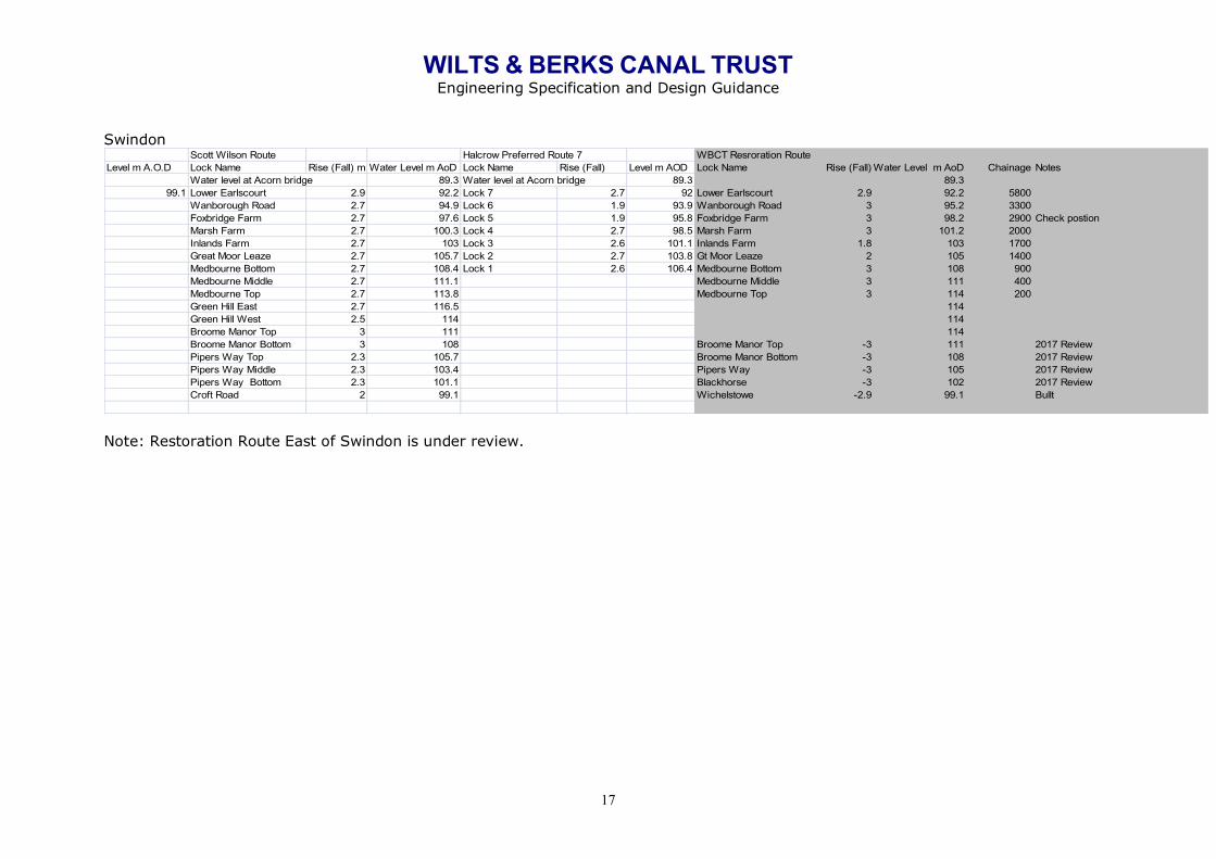
Swindon
Note: Restoration Route East of Swindon is under review.
Scott Wilson Route Halcrow Preferred Route 7 WBCT Resroration Route Level m A.O.D Lock Name Rise (Fall) m Water Level m AoD Lock Name Rise (Fall) Level m AOD Lock Name Rise (Fall) Water Level m AoD Chainage Notes
Water level at Acorn bridge 89.3 Water level at Acorn bridge 89.3 89.399.1 Lower Earlscourt 2.9 92.2 Lock 7 2.7 92 Lower Earlscourt 2.9 92.2 5800
Wanborough Road 2.7 94.9 Lock 6 1.9 93.9 Wanborough Road 3 95.2 3300Foxbridge Farm 2.7 97.6 Lock 5 1.9 95.8 Foxbridge Farm 3 98.2 2900 Check postionMarsh Farm 2.7 100.3 Lock 4 2.7 98.5 Marsh Farm 3 101.2 2000Inlands Farm 2.7 103 Lock 3 2.6 101.1 Inlands Farm 1.8 103 1700Great Moor Leaze 2.7 105.7 Lock 2 2.7 103.8 Gt Moor Leaze 2 105 1400Medbourne Bottom 2.7 108.4 Lock 1 2.6 106.4 Medbourne Bottom 3 108 900Medbourne Middle 2.7 111.1 Medbourne Middle 3 111 400Medbourne Top 2.7 113.8 Medbourne Top 3 114 200Green Hill East 2.7 116.5 114Green Hill West 2.5 114 114Broome Manor Top 3 111 114Broome Manor Bottom 3 108 Broome Manor Top -3 111 2017 ReviewPipers Way Top 2.3 105.7 Broome Manor Bottom -3 108 2017 ReviewPipers Way Middle 2.3 103.4 Pipers Way -3 105 2017 ReviewPipers Way Bottom 2.3 101.1 Blackhorse -3 102 2017 ReviewCroft Road 2 99.1 Wichelstowe -2.9 99.1 Bullt
WILTS & BERKS CANAL TRUST Engineering Specification and Design Guidance
18
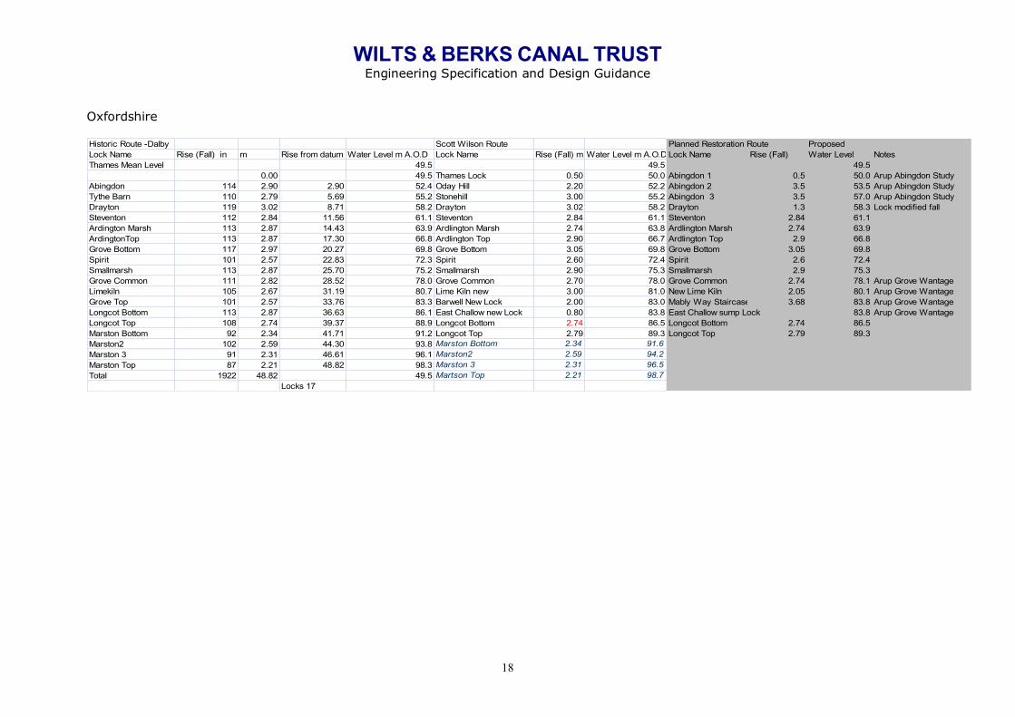
Oxfordshire
Historic Route -Dalby Scott Wilson Route Planned Restoration Route Proposed Lock Name Rise (Fall) in m Rise from datum Water Level m A.O.D Lock Name Rise (Fall) m Water Level m A.O.D Lock Name Rise (Fall) Water Level NotesThames Mean Level 49.5 49.5 49.5
0.00 49.5 Thames Lock 0.50 50.0 Abingdon 1 0.5 50.0 Arup Abingdon StudyAbingdon 114 2.90 2.90 52.4 Oday Hill 2.20 52.2 Abingdon 2 3.5 53.5 Arup Abingdon StudyTythe Barn 110 2.79 5.69 55.2 Stonehill 3.00 55.2 Abingdon 3 3.5 57.0 Arup Abingdon StudyDrayton 119 3.02 8.71 58.2 Drayton 3.02 58.2 Drayton 1.3 58.3 Lock modified fallSteventon 112 2.84 11.56 61.1 Steventon 2.84 61.1 Steventon 2.84 61.1Ardington Marsh 113 2.87 14.43 63.9 Ardlington Marsh 2.74 63.8 Ardlington Marsh 2.74 63.9ArdingtonTop 113 2.87 17.30 66.8 Ardlington Top 2.90 66.7 Ardlington Top 2.9 66.8Grove Bottom 117 2.97 20.27 69.8 Grove Bottom 3.05 69.8 Grove Bottom 3.05 69.8Spirit 101 2.57 22.83 72.3 Spirit 2.60 72.4 Spirit 2.6 72.4Smallmarsh 113 2.87 25.70 75.2 Smallmarsh 2.90 75.3 Smallmarsh 2.9 75.3Grove Common 111 2.82 28.52 78.0 Grove Common 2.70 78.0 Grove Common 2.74 78.1 Arup Grove WantageLimekiln 105 2.67 31.19 80.7 Lime Kiln new 3.00 81.0 New Lime Kiln 2.05 80.1 Arup Grove WantageGrove Top 101 2.57 33.76 83.3 Barwell New Lock 2.00 83.0 Mably Way Staircase 3.68 83.8 Arup Grove WantageLongcot Bottom 113 2.87 36.63 86.1 East Challow new Lock 0.80 83.8 East Challow sump Lock 83.8 Arup Grove WantageLongcot Top 108 2.74 39.37 88.9 Longcot Bottom 2.74 86.5 Longcot Bottom 2.74 86.5Marston Bottom 92 2.34 41.71 91.2 Longcot Top 2.79 89.3 Longcot Top 2.79 89.3Marston2 102 2.59 44.30 93.8 Marston Bottom 2.34 91.6Marston 3 91 2.31 46.61 96.1 Marston2 2.59 94.2Marston Top 87 2.21 48.82 98.3 Marston 3 2.31 96.5Total 1922 48.82 49.5 Martson Top 2.21 98.7
Locks 17

WILTS & BERKS CANAL TRUST Engineering Specification and Design Guidance
19
North Wiltshire
Historic Route Dalby Scott Wilson Route Planned Restoration Route Lock Name Rise (Fall) in m Rise from datum Water Level m AoDLock Name Rise (Fall) m Level m A.O.D Lock Name Rise (Fall) Level m AODHistoric Summit 99.1 99.1 99.1Swindon 5 55.00 1.4 97.7 Skew bridge 2.7 96.4 Town centre 1 1.7 97.4Swindon 4 63.00 1.6 96.1 GWR 2.2 94.2 Town centre 2 1.2 96.2Swindon 3 72.00 1.8 94.3 Elcombe Brook 2.2 92.0 Town centre 3 -1.4 97.6Swindon 2 67.00 1.7 92.5 Mannington 2.8 89.2 Town centre 4 -1.5 99.1Swindon 1 63.00 1.6 90.9 Rivermead -2.4 91.6 Swindon 5 1.4 97.7Moredon 3 63.00 1.6 89.3 Sparcellls Top 1.6 90.0 Swindon 4 1.6 96.1Moredon 2 68.00 1.7 87.6 Sparcells Bottom 2 88.0 Swindon 3 1.6 94.5Moredon 1 60.00 1.5 86.1 Moredon 1.5 86.5 Swindon 2 1.7 92.8Pry 60.00 1.5 84.5 Pry 1.6 84.9 Swindon 1 1.6 91.2Cross Lane 65.00 1.7 82.9 Cross Lane 1.7 83.2 Moredon 3 1.6 89.6Hayes Knoll 73.00 1.9 81.0 Hayes Knoll 1.7 81.5 Moredon 2 1.6 88.0Latton 36.00 0.9 80.1 CommonHill Bottom -3.5 85.0 Moredon 1 1.5 86.5
Common Hil Top -3.5 88.5 Pry 1.6 84.9Horsey Down Top 3.5 85.0 Cross Lane 1.7 83.2Horsey Down Bottom 3.5 81.5 Hayes Knoll 1.7 81.5Latton Regulating 81.5 Cricklade 1 2.8 78.7
81.5 Cricklade 2 1.2 77.581.5 Cricklade 3 -1.4 78.9

WILTS & BERKS CANAL TRUST WBCT Data Protection Policy
20
Lock Back-pumping & Water Supply Water resources are likely to be critical to the prospects for full restoration, and losses will need to be minimised. It is becoming more and more common to provide back-pumping facilities to recover water used in lock operations, the K&A being a prime local example. It is therefore proposed that, from the outset, back-pumping of all lockage water will be an integral feature of the Wilts & Berks restoration. In view of the disparate nature of the likely water sources, such pumping facilities may also be required for water transfer up the system and will need to be designed accordingly. In some locations, there may be a net transfer requirement down the system, after taking lockage into account; in these circumstances back-pumping would not be necessary. However, for present purposes it is assumed that a back-pumping station will be required for every lock or flight of locks. There will be an economic optimum solution in respect of the diameters and lengths of pipeline (‘rising main') and numbers of pumping stations for each location. The pumping stations can utilise either submersible (wet well) pumps (probably most common) or pumps located in a dry well, and because of the importance of this system, should include standby provision (typically 1 duty and 1 standby pump, on rotating duty to equalise hours run). Power supply to these stations will be a significant cost item, and where possible locations should be selected close to road access and power availability. Other sustainable power options would be considered. Pump sizing/capacity will depend on average filling time for a lock and the storage capacity between minimum and maximum acceptable operating water levels in the pounds connected by the station. The larger is the storage capacity, the lower the rate at which water needs to be returned, and hence the cheaper the installation and running costs. Detailed design will need to consider whether economy tariffs are available. In respect of pump control, the operation really needs to be fully automatic with a centralised telemetry and control system (SCADA system) and possibly wider access to selected data. Effective water management will be absolutely crucial to the success of full restoration. The SCADA system currently used by the CRT monitors water levels at each lock and pound and measures the inflow from water sources. Control of pumping requirements and adjustments can be managed remotely and on each individual site. By-washes. Each lock will be designed with a by-wash, generally set at an appropriate level to preferentially supply water to the next pound before it is directed away from the canal via spill weirs into local water courses. Discharge locations/flow should be carefully considered to avoid excessive flows affecting navigating craft. Pumping intakes and outfalls. Standard drawings are available and as with the by-wash discharge locations/flow should be carefully considered to avoid excessive flows affecting navigating craft.
WILTS & BERKS CANAL TRUST Engineering Specification and Design Guidance
21
Freeboard The freeboard requirement in the Specification will need to be expanded in due course to indicate maximum and absolute minimum acceptable. These could vary with location (amenity value in urban areas may dictate less tolerance of variation of levels than in the rural sections) and with season. These constraints will become important in assessing water resource issues and hydraulics, particularly back pumping and lockage. [Further guidance sections are to be developed for: 1) Locks
2) Cross-drainage culverts
3) Syphon structures
4) Spillways
5) Pumping stations
6) Pumping station pipework
7) Pumping station MCC and switchgear
8) Lining of canals
9) Sheet piling
10) Security systems
11) Public safety systems
12) Attenuation pond appurtenances]

WILTS & BERKS CANAL TRUST WBCT Data Protection Policy
22
Approvals
Name – Originator Ken Oliver Rod Hacker
Date April 2018
Name – Reviewer Richard Sewerniak
Date May 2018
Name – Chief Engineer Date
Name – Director Andrew Matters
Date June 2018
Change History
Date Version Details of Update
June 2018 1.0 Initial Issue