engineering recommendation g83 issue 2 3 (1 … part of this publication may be reproduced, ......
TRANSCRIPT

PRODUCED BY THE OPERATIONS DIRECTORATE OF ENERGY NETWORKS ASSOCIATION
www.energynetworks.org
Engineering Recommendation G83 Issue 2 3 (1 December February 201220178)
Recommendations for the Connection of Type Tested Small-scale Embedded Generators (Up to 16A per Phase) in Parallel with Low-Voltage Distribution Systems

PUBLISHING AND COPYRIGHT INFORMATION
First published, October, 2002
Amendments since publication
Issue Date Amendment
Issue 1 September 2003 Revision
Issue 1-1 June 2008 Revision (ammendment1)
Issue 2 December, 2012 Full revision of the previous version G83/1-1 2008 to ensure alignment with the requirements of EREC G59/2
Issue 3 01 February 2018 5.3.1, 5.3.3, Appendix 4
© 2012 Energy Networks Association
All rights reserved. No part of this publication may be reproduced, stored in a retrieval system or transmitted in any form or by any means, electronic, mechanical, photocopying, recording or otherwise, without the prior written consent of Energy Networks Association. Specific enquiries concerning this document should be addressed to:
Operations Directorate Energy Networks Association 6th Floor, Dean Bradley House
52 Horseferry Rd London
SW1P 2AF
This document has been prepared for use by members of the Energy Networks Association to take account of the conditions which apply to them. Advice should be taken from an appropriately qualified engineer on the suitability of this document for any other purpose.

ENA Engineering Recommendation G83 Issue 2 2012
Page 3
Contents
1 Foreword .............................................................................................................................. 5
2 Scope ................................................................................................................................... 6
3 Normative References ......................................................................................................... 7
4 Terms and Definitions.......................................................................................................... 9
5 Connection, Protection & Testing Requirements .............................................................. 13
5.1 Connection Procedure ............................................................................................. 13 5.1.1 Single Premises Connection Procedure ...................................................... 13 5.1.2 Multiple Premises Connection Procedure ................................................... 13
5.2 Installation Wiring and Isolation ............................................................................... 14 5.3 Interface Protection ................................................................................................. 14
5.3.1 Interface Protection Settings and Test Requirements ................................ 14 5.3.2 Loss of Mains Protection ............................................................................. 16 5.3.3 Frequency Drift and Step Change Stability Test ......................................... 16 5.3.4 Automatic Reconnection .............................................................................. 16
5.4 Quality of Supply ...................................................................................................... 17 5.4.1 Testing for Harmonic emissions. ................................................................. 17 5.4.2 Testing for flicker .......................................................................................... 17
5.5 DC Injection .............................................................................................................. 19 5.6 Power Factor ............................................................................................................ 19 5.7 Short Circuit Current Contribution ............................................................................ 19
5.7.1 Directly Coupled Generation........................................................................ 19 5.7.2 Inverter Connected Generation ................................................................... 20
5.8 Voltage Unbalance ................................................................................................... 20 5.9 Certification Requirements ....................................................................................... 20
5.9.1 General......................................................................................................... 20 5.9.2 Compliance .................................................................................................. 21 5.9.3 Verification Test Report ............................................................................... 21
6 Operation and Safety......................................................................................................... 21
6.1 Operational Requirements ....................................................................................... 21 6.2 Labelling ................................................................................................................... 21 6.3 Maintenance & Routine Testing ............................................................................... 22 6.4 Earthing .................................................................................................................... 22
7 Commissioning/Decommissioning and Acceptance Testing ........................................... 23
7.1 General ..................................................................................................................... 23 7.2 Installation and Commissioning ............................................................................... 23 7.3 Notification of Commissioning.................................................................................. 24 7.4 Notification of Changes ............................................................................................ 24 7.5 Notification of Decommissioning .............................................................................. 24
Appendix 1 Connection Procedure Flow Chart .............................................................. 25
Appendix 2 Application for Connection ........................................................................... 26
Appendix 3 SSEG Installation Commissioning Confirmation ......................................... 27

ENA Engineering Recommendation G83 Issue 2 2012 Page 4
Appendix 4 Type Verification Test Report ...................................................................... 28
Appendix 5 SSEG Decommissioning Confirmation........................................................ 36
Appendix 6 Relaxation of Commissioning Notification Timescales for SSEG: HSE Certificate of Exemption (August 2008) .............................................. 37
Annex A-C Guidance on Type Testing Requirements ................................................... 38
Annex A1 Common Inverter Connected SSEG Requirements ................................... 39 Annex B1 Common Directly Coupled Connected SSEG Requirements ..................... 46 Annex C1 Separate Specific SSEG Technology Requirements .................................. 52
C1.1 Domestic CHP .............................................................................................. 52 C1.2 Photovoltaic.................................................................................................. 52 C1.3 Fuel Cells ..................................................................................................... 52 C1.4 Hydro ............................................................................................................ 52 C1.5 Wind ............................................................................................................. 52 C1.6 Energy Storage Device ................................................................................ 53

ENA Engineering Recommendation G83 Issue 2 2012
Page 5
1 Foreword
This Engineering Recommendation (EREC) is published by the Energy Networks Association (ENA) and comes into effect from 1 December 20121. It has been prepared and approved under the authority of the Great Britain Distribution Code Review Panel. The approved abbreviated title of this engineering document is “EREC G83”, which replaces the previously used abbreviation “ER G83”.
The purpose of this Engineering Recommendation is to simplify and standardise the technical requirements for connection of Small Scale Embedded Generators (SSEGs) for operation in parallel with a public low-voltage Distribution System, by addressing all technical aspects of the connection process from standards of functionality to site commissioning. The procedures described are designed to facilitate the connection of Type Tested SSEGs whilst maintaining the integrity of the public low-voltage Distribution System, both in terms of safety and supply quality. This Engineering Recommendation provides sufficient information to allow: a) SSEG Manufacturers to design and market a product that is suitable for connection to the public low-voltage Distribution System; b) Users, Manufacturers and Installers of SSEGs to be aware of the requirements that will be made by the Distribution Network Operator (DNO) before the SSEG installation will be accepted for connection to the DNO’s Distribution System. Legal Aspects In accordance with ESQCR Regulation 22(2)(c) the Installer is to ensure that the DNO is made aware of the SSEG installation at or before the time of commissioning. The DNO may not refuse to accept the connection providing the installation complies with the requirements of ESQCR Regulation 22. However under the terms of ESQCR Regulation 26 the DNO may require a SSEG to be disconnected if it is a source of danger or interferes with the quality of supply to other consumers. In August 2008 an exemption to ESQCR Regulation 22(2) (c) was granted by the Health & Safety Executive to the person or persons installing the source of energy from the requirements imposed by ESQCR Regulation 22(2)(c) as long as that person or persons installing the source of energy informed the DNO of the intention to use that source of energy in parallel with the network no later than 28 days (inclusive of the day of commissioning) after commissioning the source (see Appendix 6)
In addition to the requirements specified in this document which allows connection to the GB electricity Distribution System, the SSEG and all of its components shall comply with all relevant legal requirements including European Directives and CE marking.
————————— 1 Distribution Code Guidance Note 2/4 - December 2012. - http://www.energynetworks.info/the-distribution-code/
For all Small Scale Embedded Generators (SSEG) of up to 16A per phase, until 1 March 2014 it is permissible to connect to the general requirements of previous versions of G83 provided this is through an Inverter or Controller with a protection/control system that has either been fully type tested in accordance with G83/1-1, G83/2 or in accordance with G59/2.
After 1 March 2014 it will only be allowable to connect SSEG of up to 16A per phase that complies with G83/2.
ENA Engineering Recommendation G83 Issue 2 2012 Page 6
2 Scope
This Engineering Recommendation provides guidance on the technical requirements for the connection of Type Tested Small-Scale Embedded Generators (SSEGs) in parallel with public low-voltage distribution networks. For the purposes of this Engineering Recommendation a SSEG is a source of electrical energy rated up to and including 16 Ampere per phase, single or multi- phase, 230/400 V AC. This corresponds to 3.68 kilowatts (kW) on a single-phase supply and 11.04 kW on a three-phase supply. The kW rating shall be based on the nominal voltage (ie 230V) as defined in BS EN 50160 and the Electricity Supply Quality and Continuity Regulations (ESQCR). Where the SSEG includes an Inverter its rating is deemed to be the Inverter’s continuous steady state rating. There are two connection procedures described in this document. The first connection procedure covers the connection of o ne o r more SSEG systems, either single or multi-phase within a single Customer’s Installation. Multiple SSEG systems shall be accepted within a single Customers Installation provided that the aggregate rated capacity of the systems is not greater than 16A per phase2. The second connection procedure covers the connection of multiple SSEGs (other than within a single Customer’s Installation) in a Close Geographic Region, under a planned programme of work. This Engineering Recommendation only specifies the connection requirements applicable to those SSEG installations that are designed to normally operate in parallel with a public distribution network. Those installations that operate in parallel with the DNO’s Distribution System for short periods (ie less than 5 minutes) or as an islanded installation or section of network are considered to be out of scope, on the basis that it is not possible to devise generic rules that will ensure safe operation under all operating conditions. The generic requirements for all types of SSEG systems are defined in the main text of this Engineering Recommendation, whilst the generic and technology specif ic type testing requirements are defined in the annexes. The generic requirements relate to the connection, installation and network design requirements for connection of a SSEG to a public low-voltage Distribution System. SSEGs that are not Type Tested to conform to the requirements of this document can only be connected via the guidelines laid down in Engineering Recommendation G59. Annexes A and B describe a methodology for testing the particular types of electrical interface between the SSEG and the Distribution System whilst Annex C describes a methodology for testing technology specific SSEG requirements. The purpose of the type tests is to demonstrate compliance with the generic requirements of this Engineering Recommendation. By satisfying the test conditions in the relevant annex the SSEG can be considered an approved SSEG for connection to a public low-voltage Distribution System. In the event that a new type testing annex is required then this should be formally initiated by the GB Distribution Code Review Panel (DCRP).
————————— 2 The manufacturer may restrict the rating of the SSEG by applying software settings provided these settings are
not accessible to the customer

ENA Engineering Recommendation G83 Issue 2 2012
Page 7
The Appendices contain pro forma that relate to the connection, commissioning, type testing, and decommissioning of SSEGs. This document does not remove any statutory rights of an individual or organisation; equally it does not remove any statutory obligation on an individual or organisation. Connection agreements (ie the legal documentation supporting the connection of a SSEG), energy trading and metering are considered to be out of scope. These issues are mentioned in this document only in the context of raising the reader’s awareness to the fact that these matters might need to be addressed
3 Normative References
The following referenced documents, in whole or part, are indispensable for the application of this document. For dated references, only the edition cited applies. For undated references, the latest edition of the referenced document (including any amendments) applies.
Standards publications
BS 7671: 2008 Requirements for Electrical Installations IEE Wiring Regulations Seventeenth (Amendment 1 2011) Edition. BS EN 50160: 2010 Voltage characteristics of electricity supplied by public electricity networks.
BS EN 50438: 2008 Requirements for the connection of micro-generators in parallel with public low-voltage distribution networks.
BS EN 60034-4:2008 Methods for determining synchronous machine quantities from tests.
BS EN 60255 series* Measuring relays and protection equipment.
BS EN 60664-1: 2007 Insulation coordination for equipment within low-voltage systems – Part 1: Principles, requirements and tests (IEC 60664-1:2007).
BS EN 60947 series* Low Voltage Switchgear and Controlgear.
BS EN 61000-3-2:2006+A2:2009 Limits for harmonic current emissions (equipment input current up to and including 16 A per phase). BS EN 61000-3-3:2008 Limits – Limitation of voltage changes, voltage fluctuations and flicker in public low-voltage supply systems, for equipment with rated current < 16A per phase and not subject to conditional connection. BS EN 61000 series* Electromagnetic Compatibility (EMC).
ENA Engineering Recommendation G83 Issue 2 2012 Page 8
BS EN 61508 series* Functional safety of electrical/ electronic/ programmable electronic safety-related systems. BS EN 61810 series* Electromechanical Elementary Relays. BS EN 62116 Test procedure of islanding prevention measures for utility-interconnected photovoltaic Inverters. IEC 60255-5: 2001 Electrical relays. Insulation coordination for measuring relays and protection equipment. Requirements and tests. IEC 60725 Considerations or reference impedances for use in determining the disturbance characteristics of household appliances and similar electrical equipment. IEC 60909-1 (Second Edition): 2002 Short circuit calculation in three-phase AC systems. IEC 62282-3-2 ed1.0: 2006 Fuel cell technologies - Part 3-2: Stationary fuel cell power systems - Performance test methods. *Where standards have more than one part, the requirements of all such parts shall be satisfied, so far as they are applicable. Other publications
Health and Safety at Work etc Act (HASWA): 1974 The Health and Safety at Work etc Act 1974 also referred to as HASAW or HSW, is the primary piece of legislation covering occupational health and safety in the United Kingdom. The Health and Safety Executive is responsible for enforcing the Act and a number of other Acts and Statutory Instruments relevant to the working environment. Electricity Safety, Quality and Continuity Regulations (ESQCR) The Electricity Safety, Quality and Continuity Regulations 2002 - Statutory Instrument Number 2665 -HMSO ISBN 0-11-042920-6 abbreviated to ESQCR in this document. Electricity at Work Regulations (EaWR): 1989 The Electricity at Work regulations 1989 abbreviated to EaWR in this document. Engineering Recommendation G5/4-1 (2005) Planning levels for harmonic voltage distortion and the connection of non-linear equipment to transmission and distribution networks in the United Kingdom.
Engineering Recommendation G59/2, Amendment 1 (2011) Recommendations for the Connection of Embedded Generating Plant to the Distribution Systems of Licensed Distribution Network Operators. Engineering Recommendation P28 (1989) Planning limits for voltage fluctuations caused by industrial, commercial and domestic equipment in the United Kingdom.

ENA Engineering Recommendation G83 Issue 2 2012
Page 9
Engineering Recommendation P29 (1990) Planning limits for voltage unbalance in the UK for 132kV and below. Engineering Recommendation G74 (1992) Procedure to meet the requirements of IEC 60909 for the calculation of short-circuit currents in three-phase AC power systems.
4 Terms and Definitions
For the purposes of this document, the following terms and definitions apply.
NOTE: Defined terms are capitalised and in bold script where they are used in the main text of this report.
Alternating Current or AC An electric current that reverses direction in a circuit at regular intervals. Act The Electricity Act 1989 (as amended by the Utilities Act 2000 and the Energy Act 2004). Apparatus All Equipment, in which electrical conductors are used, supported or of which they may form a part. Authorised Electricity Operators Any person (other than the DNO in its capacity as an operator of a Distribution System) who is authorised to generate, participate in the transmission of, distribute or supply electricity. Authority The Gas and Electricity Markets Authority established under Section 1 of the Utilities Act 2000. Circuit Breaker An automatically operated electrical switch designed to protect an electrical circuit from damage caused by overload or short circuit.
Close Geographic Region A close geographic region is defined as the area typically served by a single low voltage feeder circuit fed from a single distribution transformer. In a situation where this definition cannot be reliably applied by an Installer, the Installer can either confirm with the DNO whether a proposed SSEG is in a Close Geographic Region or ensure that at least one of the following criteria is met: 1) The postcodes of any of the premises where a SSEG installation is planned by the same organisation are the same when the last two letters are ignored…i.e. AB1 2xx, where xx could be any pair of letters or where x could be any letter. 2) The premises where a SSEG installation is planned by the same organisation are within 500m of each other. Connection Point An Entry Point or an Exit Point of the Distribution System as the case may be.

ENA Engineering Recommendation G83 Issue 2 2012 Page 10
Controller A device for controlling the functional operation of an SSEG. Converter The generic name for electronic architecture that, for the purpose of this recommendation, converts either an alternating (AC) or direct (DC) current input into alternating current (AC) output suitable for direct connection to the DNO’s Distribution System. Customer Any person supplied or entitled to be supplied with electricity at any premises within Great Britain but shall not include any Authorised Electricity Operator in its capacity as such. NOTE: Other documentation may use the term Consumer when making reference to the functions and/or features that this document has attributed to the Customer. Customer's Installation The electrical installation on the Customer's side of the Exit Point together with any equipment permanently connected or intended to be permanently connected thereto. Customer With Own Generation A Customer with one or more Generation Sets connected to the Customer’s System, providing all or part of the Customer’s electricity requirements, and which may use the DNO’s Distribution System for the transport of any surplus of electricity being exported. Direct Current or DC The movement of electrical current flows in one constant direction, as opposed to Alternating Current or AC, in which the current constantly reverses direction. Distribution Code A code required to be prepared by a DNO pursuant to condition 9 (Distribution Code) of a Distribution Licence and approved by the Authority as revised from time to time with the approval of, or by the direction of, the Authority. Distribution Code Review Panel (DCRP) The standing body established under the Distribution Code. Distribution Licence A distribution licence granted under Section 6(1)(c) of the Act. Distribution Network Operator (DNO) The person or legal entity named in Part 1 of the Distribution Licence and any permitted legal assigns or successors in title of the named party. Distribution System The electrical network operated by an Other Authorised Distributor. DNO’s Distribution System The System consisting (wholly or mainly) of electric lines owned or operated by the DNO and used for the distribution of electricity Equipment Plant and/or Apparatus.

ENA Engineering Recommendation G83 Issue 2 2012
Page 11
Embedded Generator A Generator including a Customer With Own Generation whose Generating Units are directly connected to the DNO’s Distribution System or to an Other Authorised Distributor connected to the DNO’s Distribution System. Entry Point The point at which an Embedded Generator or other Users connect to the DNO’s Distribution System where power flows into the DNO’s Distribution System under normal circumstances. Exit Point Means the ends of the electric lines at which the supply is delivered to a Customer’s Installation. Generator A person who generates electricity under licence or exemption under the Act. Generation Set Any Apparatus which produces electricity. Generating Unit Any Apparatus which produces electricity. Great Britain or GB The landmass of England & Wales and Scotland, including internal waters. Installer The person who is responsible for the installation of the SSEG.
Interface Protection The electrical protection required to ensure that the SSEG is disconnected for any event that could impair the integrity or degrade the safety of the Distribution System. This protection will normally include the elements detailed in Table 1 of this Engineering Recommendation. Inverter A device for conversion from Direct Current to nominal frequency Alternating Current. Islanding Any situation where a section of electricity system, containing generation, becomes physically disconnected from the DNO’s Distribution System or User’s Distribution System; and one or more Generating Units maintains a supply of electrical energy to that isolated system. Low Voltage or LV In relation to Alternating Current, a voltage exceeding 50 volts but not exceeding 1000 volts. Manufacturer A person or organisation that manufactures SSEG and also ‘packages’ components manufactured by others to make a SSEG which can be Type Tested to meet the requirements of this Engineering Recommendation.

ENA Engineering Recommendation G83 Issue 2 2012 Page 12
Meter Operator A person, registered with the registration Authority, appointed by either a Supplier or Customer to provide electricity meter operation services. (This Distribution Code does not place any direct obligation on Meter Operators other than through the appointment by either a Supplier or a Customer.) Nominal Voltage and Frequency Low voltage: 230 volts AC (+10/-6 %) single-phase, 50 Hz (±1%).400 volts AC (+10/-6 %) three phase, 50 Hz (±1%). 230-460 volts AC (+10/-6%) split phase. NOTE: DNO voltage and frequency is referenced to the Exit Point. Plant Fixed and movable items used in the generation and/or supply and/or transmission of electricity other than Apparatus. Other Authorised Distributor A User authorised by Licence or exemption to distribute electricity and having a User Distribution System connected to the DNO’s Distribution System. Quality Factor, Qf A measure of the strength of resonance of the Islanding test load.
NOTE: In a parallel resonant circuit, such as a load on a power system.
Where Qf is quality factor, R is effective load resistance, C is reactive load capacitance (including shunt capacitors), and L is reactive load inductance.
On a power system with active power, P, and reactive powers, QL, for inductive load, and QC for capacitive load, Qf can be determined by:
Where P is active power, in W, QL is inductive load, in VAr, and QC is capacitive load, in VAr. Small Scale Embedded Generator (SSEG) A Generating Unit together with any associated interface equipment, if required, (eg Inverter(s)) that can be used independently, rated up to and including 16A per phase, single or multi-phase 230/400V AC and designed to operate in parallel with a public low voltage Distribution System. 16A is equivalent to 3.68kW on a single-phase supply and 11.04kW on a three-phase supply. Where the SSEG includes an Inverter its rating is deemed to be the Inverter’s continuous steady state rating. Supplier (a) A person supplying electricity under an Electricity Supply Licence; or (b) A person supplying electricity under exemption under the Act; in each case acting in its capacity as a Supplier of electricity to Customers.

ENA Engineering Recommendation G83 Issue 2 2012
Page 13
System An electrical network running at various voltages. Type Tested An SSEG design which has been tested by the Manufacturer, component manufacturer or supplier, or a third party, to ensure that the design meets the requirements of this Engineering Recommendation, and for which the Manufacturer has declared that all products supplied will be constructed to the same standards, and with the same protection settings as the tested product. User A term used in various sections of the Distribution Code to refer to the persons using the DNO’s Distribution System.
5 Connection, Protection & Testing Requirements
5.1 Connection Procedure 5.1.1 Single Premises Connection Procedure In most instances the installation of a single SSEG or multiple SSEGs (provided that the aggregate installed capacity is no greater than 16A per phase) within a single Customer’s Installation, connected in parallel with the public Distribution System, will have negligible impact on the operation of the Distribution System; as such there will be no need for the DNO to carry out detailed network studies to assess the impact of the connection. A s re q u i re d b y the ESQCR Certificate of Exemption (2008) (see Appendix 6) the Installer shall provide the DNO with all necessary information on the installation no later than 28 days after the SSEG(s) have been commissioned; the format and content shall be as shown in Appendix 3. This procedure will not apply where an Installer plans (within the next 28 days) or has already installed (in the previous 28 days) other SSEGs in a Close Geographic Region; in this case the procedure in 5.1.2 shall be followed. Failure to comply with this requirement may lead to the disconnection of the Customer‟s Installation under ESQCR (26) or failure of the SSEG to operate as intended. 5.1.2 Multiple Premises Connection Procedure In the case of projects where the proposal is to install single or multiple SSEGs in a number of Customers Installations in a Close Geographic Region, the Installer shall discuss the installation project with the local DNO at the earliest opportunity. The DNO will need to assess the impact that these connections may have on the network and specify conditions for connection. The initial application will need to be in a format similar to that shown in Appendix 2. Connection of the SSEG is only allowed after the application for connection has been approved by the DNO and any DNO works facilitating the connection have been completed. Confirmation of the commissioning of each SSEG system will need to be made no later than 28 days after commissioning; the format and content shall be as shown in Appendix 3.

ENA Engineering Recommendation G83 Issue 2 2012 Page 14
5.2 Installation Wiring and Isolation The installation that connects the SSEG to the Exit Point shall comply with the requirements of BS 7671. All wiring between the Exit Point and the SSEG shall be protected by a suitably rated protective device; and shall be of suitable size and type for the rating of the SSEG. The SSEG(s) shall be connected via an accessible isolation switch that is capable of isolating all phases and neutral. The isolation switch shall be capable of being secured in the ‘off’ (isolated) position.
5.3 Interface Protection The purpose of the Interface Protection is to ensure that the connection of a SSEG system will not impair the integrity or degrade the safety of the DNO’s Distribution System. The interface protection may be located in a separate unit or integrated into the SSEG (the Inverter in the case of technologies which connect via an Inverter). The DNO is responsible under the Distribution Code for ensuring, by design, that the voltage and frequency at the Connection Point remains within statutory limits. The G83/2 Interface Protection settings have been chosen to allow for voltage rise or drop within the Customer’s Installation and to allow the SSEG to continue to operate outside of the statutory frequency range as required in the Distribution Code. 5.3.1 Interface Protection Settings and Test Requirements Interface Protection shall be installed which disconnects the SSEG system from the DNO’s Distribution System when any parameter is outside of the settings shown in Table 1. Table 1 Protection Settings Protection Function Trip Setting Trip Delay Setting (Time) U/V stage 1 Vφ-n† -13% = 200.1V 2.5s U/V stage 2 Vφ-n† - 20% = 184V 0.5s O/V stage 1 Vφ-n† +14% = 262.2V 1.0s O/V stage 2 Vφ-n†+ 19% = 273.7V3 0.5s U/F stage 1 47.5Hz 20s U/F stage 2 47Hz 0.5s O/F stage 1 51.5Hz 90s O/F stage 2 52 Hz 0.5s Loss of Mains* (Vector Shift)
12 degrees 0.0s
Loss of Mains*¶ (RoCoF)
1.0.2 Hz per second 0.50s
† A value of 230V phase to neutral * Other forms of Loss of Mains techniques may be utilised but the aggregate of the protection operating time, disconnection device operating time and trip delay setting shall not exceed 1.0 second. ¶The required protection requirement is expressed in Hertz per second (Hz/s). The time delay should begin when the measured RoCoF exceeds the threshold expressed in Hz/s. The time delay should be reset if measured
————————— 3 For grid surge voltages greater than 230V +19% which are present for periods of <0.5s the SSEG is permitted to
reduce/cease exporting in order to protect the equipment.
Formatted: Superscript
Formatted: Font: 10 pt
Formatted: Font: 9 pt
Formatted: Font: (Default) Arial, 9 pt

ENA Engineering Recommendation G83 Issue 2 2012
Page 15
RoCoF falls below that threshold. The relay must not trip unless the measured rate remains above the threshold expressed in Hz/s continuously for 500ms. Setting the number of cycles on the relay used to calculate the RoCoF is not an acceptable implementation of the time delay since the relay would trip in less than 500ms if the system RoCoF was significantly higher than the threshold
The total disconnection time for voltage and frequency protection including the operating time of the disconnection device shall be the trip delay setting with a tolerance of, -0 s + 0.5s. For the avoidance of doubt voltage and frequency excursions lasting less than the trip delay setting shall not result in disconnection. All settings shall be applied as shown in the above table, so that they can be inspected if required by the DNO to confirm that the settings are correct. Only devices that have protection settings set and locked during manufacture can be considered as Type Tested. The Manufacturer needs to establish a secure way of displaying the settings in one of the following ways.
a) A display on a screen which can be read; b) A display on a PC which can communicate with the device and confirm that it is the
correct device by means of a serial number permanently fixed to the device and visible on the PC screen at the same time as the settings;
c) Display of all settings including nominal voltage and current outputs, alongside the serial number of the device, permanently fixed to the device.
The provision of loose documents, documents attached by cable ties etc, a statement that the device conforms to a standard, or provision of data on adhesive paper based products which are not likely to survive due to fading, or failure of the adhesive, for at least 20 years is not acceptable. The Manufacturer must ensure that the Interface Protection is capable of measuring voltage to an accuracy of ± 1.5% of the nominal value (± 3.45V) and of measuring frequency to ± 0.2% of the nominal value (± 0.1Hz) across its operating range of voltage, frequency and temperature. The SSEG shall be designed to withstand without adverse effect, voltage and frequency variations within the settings shown in Table 1 plus the measurement error inherent in the device itself. In response to a protection operation the SSEG system shall be automatically disconnected from the DNO’s Distribution System, this disconnection must be achieved preferably by the separation of mechanical contacts or alternatively by the operation of a suitably rated solid state switching device. Where a solid state switching device is used to afford disconnection of the SSEG, the switching device shall incorporate fail safe monitoring to check the voltage level at its output stage. In the event that the solid state switching device fails to disconnect the SSEG, the voltage on the output side of the switching device shall be reduced to a value below 50 volts within 0.5 seconds of the protection and trip delay timer operation. The protection function can either be incorporated within the SSEG system or afforded by separate devices. In either case the Interface Protection shall meet the requirements of BS EN 60255 or equivalent standard and comply with all other relevant standards as described in the appropriate annex. Where these standards have more than one part, the requirements of all such parts shall be satisfied, so far as they are applicable. The Interface Protection shall function correctly, ie operate within the required tolerance range as given in the relevant annex, across the expected range of ambient operating
Formatted: Font: 8 pt

ENA Engineering Recommendation G83 Issue 2 2012 Page 16
temperatures and other environmental factors. Once the SSEG has been installed and commissioned the protection settings shall only be altered following written agreement between the DNO and the Customer or his agent. 5.3.2 Loss of Mains Protection Loss of mains protection shall be incorporated and tested as defined in the relevant annex. Active methods which use impedance measuring techniques by drawing current pulses from or injecting AC currents into the DNO’s system are not considered to be suitable. For SSEGs which generate on more than one phase, the loss of mains protection should be able to detect the loss of a single phase of the supply network. This should be tested during type testing and recorded on in Appendix 4.
5.3.3 Frequency Drift and Step Change Stability Test
Under normal operation of the network the frequency changes over time due to continuous unbalance of load and generation or can see a step change due to the loss of a network component which does not cause a loss of supply. In order to ensure that the phenomena do not cause un-necessary tripping of SSEG, stability Type Tests shall be carried out. The Rate of Change of Frequency (RoCoF) and Vector Shift values required for this test are marginally less than the corresponding protection settings for RoCoF protection and Vector shift protection in Table 1 and vector shifts of up to 50º. These are two common methods used to detect loss of mains in SSEG’s though other techniques are also acceptable. Both stability tests shall be carried out irrespective of the methods used to detect loss of mainsin all cases. National Grid has advised that these test values are acceptable in the short term but that in future it is likely that larger rates of change of frequency might need to be withstood without tripping, as system inertia decreases at times when a high proportion of the load is being met by generation without inertia. The stability tests are to be carried out as per the table in Appendix 4 of this document and the generator should remain connected during each and every test.
• RoCoF - 0.190.95 Hz per second from in the range 49.5Hz 0Hz to 51.5Hz 0Hz on both rising and falling frequencyand from 50.5Hz to 47.5Hz
• Vector shift - 9 50º degrees plus from 49.5Hz and 50º 9 degrees minus from 50.5Hz
Note: Manufacturers considering new designs should allow for the RoCoF where stability is required to be increased to, up to 2Hz per second, as proposed in the new European network codes, which are expected to come into force over the period 2014/2015. Under these conditions RoCoF will cease to be an effective loss of mains protection and is unlikely to be permitted in future revisions of this document. 5.3.4 Automatic Reconnection Some Distribution Systems employ automatic Circuit Breakers that trip and re-close when a fault is detected. In order to prevent a SSEG being damaged by a DNO Circuit Breaker automatically closing and consequently energising a SSEG when it is out of synchronism with the rest of the system, the protection system shall ensure that the SSEG remains
ENA Engineering Recommendation G83 Issue 2 2012
Page 17
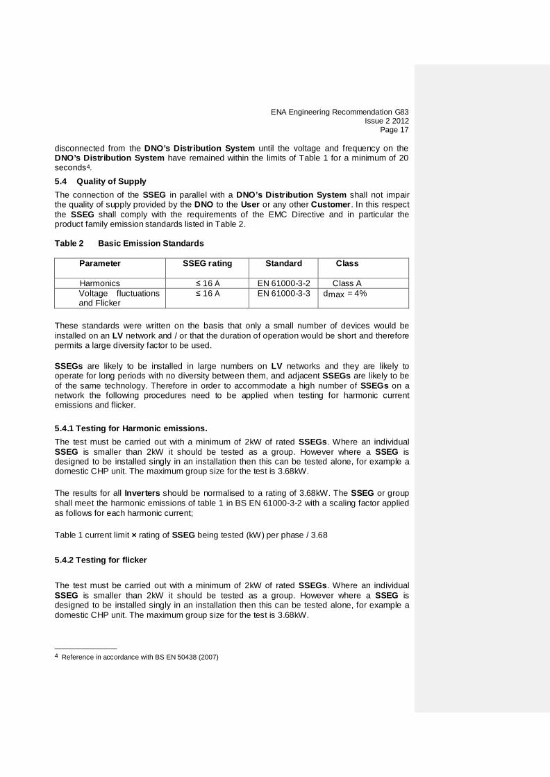
disconnected from the DNO’s Distribution System until the voltage and frequency on the DNO’s Distribution System have remained within the limits of Table 1 for a minimum of 20 seconds4. 5.4 Quality of Supply The connection of the SSEG in parallel with a DNO’s Distribution System shall not impair the quality of supply provided by the DNO to the User or any other Customer. In this respect the SSEG shall comply with the requirements of the EMC Directive and in particular the product family emission standards listed in Table 2. Table 2 Basic Emission Standards
Parameter SSEG rating Standard Class
Harmonics ≤ 16 A EN 61000-3-2 Class A Voltage fluctuations
and Flicker ≤ 16 A EN 61000-3-3 dmax = 4%
These standards were written on the basis that only a small number of devices would be installed on an LV network and / or that the duration of operation would be short and therefore permits a large diversity factor to be used. SSEGs are likely to be installed in large numbers on LV networks and they are likely to operate for long periods with no diversity between them, and adjacent SSEGs are likely to be of the same technology. Therefore in order to accommodate a high number of SSEGs on a network the following procedures need to be applied when testing for harmonic current emissions and flicker. 5.4.1 Testing for Harmonic emissions. The test must be carried out with a minimum of 2kW of rated SSEGs. Where an individual SSEG is smaller than 2kW it should be tested as a group. However where a SSEG is designed to be installed singly in an installation then this can be tested alone, for example a domestic CHP unit. The maximum group size for the test is 3.68kW. The results for all Inverters should be normalised to a rating of 3.68kW. The SSEG or group shall meet the harmonic emissions of table 1 in BS EN 61000-3-2 with a scaling factor applied as follows for each harmonic current;
Table 1 current limit × rating of SSEG being tested (kW) per phase / 3.68 5.4.2 Testing for flicker The test must be carried out with a minimum of 2kW of rated SSEGs. Where an individual SSEG is smaller than 2kW it should be tested as a group. However where a SSEG is designed to be installed singly in an installation then this can be tested alone, for example a domestic CHP unit. The maximum group size for the test is 3.68kW.
————————— 4 Reference in accordance with BS EN 50438 (2007)

ENA Engineering Recommendation G83 Issue 2 2012 Page 18
The SSEG or group shall meet the required dmax, dc, d(t), Pst, Plt requirements of BS EN 61000-3-3 with a scaling factor applied as follows for each voltage change component.
dmax, dc, d(t), Pst, Plt × rating of SSEG being tested (kW) per phase / 3.68
The results for groups of Inverters should be normalised to a rating of 3.68kW and to the standard source impedance. Single Inverters need to be normalised to the standard source impedance, these normalised results need to comply with the limits set out in Appendix 4. For voltage change and flicker measurements the following simplified formula is to be used to convert the measured values to the normalised values where the power factor of the generation output is 0.98 or above. Where it is less than 0.98 then compliance with the full requirements of BS EN 61000-3-3 is required. Normalised value = Measured value × reference source resistance/measured source resistance at test point. And for units which are tested as a group. Normalised value = Measured value × reference source resistance/measured source resistance at test point × 3.68/rating per phase. Single phase units reference source resistance is 0.4 ohms Two phase units in a three phase system reference source resistance is 0.4 ohms Two phase units in a split phase system reference source resistance is 0.24 ohms Three phase units reference source resistance is 0.24 ohms. The stopping test should be a trip from full load generation. The duration of these tests need to comply with the particular requirements set out in the testing notes for the technology under test and can be found in annex C. The dates and location of the tests need to be noted in Appendix 4 Note: For wind turbines, flicker testing should be carried out during the performance tests specified in IEC 61400-12-1. Flicker data should be recorded from wind speeds of 1m/s below cut-in to 1.5 times 85% of the rated power. The wind speed range should be divided into contiguous bins of 1m/s centred on multiples of 1m/s. The dataset shall be considered complete when each bin includes a minimum of 10 minutes of sampled data. The highest value of each parameter measured across the entire range of tests shall be recorded. Note that as an alternative to Type Testing the supplier of a SSEG incorporating an Inverter may give a guarantee that rates of change of output do not exceed the following ramp rate limits. Output needs to ramp up at a constant rate This exception to site testing does not apply to devices where the output changes in steps of over 30ms rather than as a ramp function, a site test is required for these units. Single phase units and two phase units in a three phase system, maximum ramp up rate 333 watts per second; Two phase units in a split phase system and three phase units, maximum ramp up rate 860 watts per second.
It should be noted that units complying with this declaration are likely to be less efficient at capturing energy during times when the energy source is changing.
ENA Engineering Recommendation G83 Issue 2 2012
Page 19
For technologies other than wind turbines, testing should ensure that the controls or automatic programs used produce the most unfavourable sequence of voltage changes. 5.5 DC Injection The effects of, and therefore limits for, DC currents injected in the DNO’s Distribution System is an area under current investigation by DNOs. Until these investigations are concluded the upper limit for DC injection is 0.25% of AC current rating per phase. Where a SSEG is designed to be installed singly in an installation, for example a domestic CHP unit, then this DC injection limit can be a maximum value of 20mA for sub 2kW SSEG and can be tested alone,. Where SSEGs are designed such that multiple units may be installed in an installation for example roof mounted wind turbines and PV with micro Inverters on each panel, then they should be tested as a group of at least 2kW and with a maximum group size of 4kW. Tests are to be carried out a three power levels plus or minus 5%. At 230V a 2kW single phase Inverter has a current output of 8.7A so DC limit is 21.75mA; a 10kW three phase Inverter has a current output of 14.5A per phase which is equivalent to a total of 43.5A at 230V so DC limit is 108.75mA. Where necessary the DC emission requirements can also be satisfied by installing an isolating transformer between the Inverter and the connection to the DNO’s Distribution System. 5.6 Power Factor When operating at rated power the SSEG shall operate at a power factor within the range 0.95 lagging to 0.95 leading relative to the voltage waveform unless otherwise agreed with the DNO eg for power factor improvement. 5.7 Short Circuit Current Contribution 5.7.1 Directly Coupled Generation The Manufacturer shall establish the maximum short circuit current contribution from the SSEG and the conditions under which this exists. This information shall be provided to the DNO by the Installer as part of the commissioning notification as per Appendix 3. One method for determining the short circuit current contribution is described below. The short circuit current contribution of the SSEG shall be measured upon application of a short circuit on the SSEG terminals (all phases / phase to neutral) with the SSEG operating at rated output steady state conditions. Current measurements shall be taken from application of fault until the time the fault has been disconnected, following operation of the SSEG protection. A current decay plot shall be produced for each phase from inception of the fault until SSEG has been disconnected – trip time. The plot will need to show the highest value of peak short circuit current, eg for a SSEG supplying a purely inductive load the highest value of peak short circuit current will result when the fault is applied at a voltage zero. Where practicable the tests will need to determine values for all of the relevant parameters listed in Table 3.

ENA Engineering Recommendation G83 Issue 2 2012 Page 20
These parameters are described in IEC 60909-1, whilst this standard is primarily for three-phase generators the methodology for determining these parameters can be applied to single-phase generators. Table 3. SSEG Short Circuit Parameters Parameter Symbol Method of Determination Peak short-circuit current
ip Direct measurement
Initial value of aperiodic component A Direct measurement
Initial symmetrical short-circuit current
Ik” Interpolation of plot
Decaying (aperiodic) component of short- circuit current
idc Interpolation of plot & calculation
Reactance / Resistance ratio of source
X/R
Calculation
5.7.2 Inverter Connected Generation Inverter connected SSEGs generally have small short circuit fault contributions.
However DNOs need to understand the contribution that they do make to system fault levels in order to determine that they can continue to safely operate without exceeding design fault levels for switchgear and other circuit components. As the output from an Inverter reduces to zero when a short circuit is applied to its terminals, a short circuit test does not represent the worst case scenario; in most cases the voltage will not collapse to zero for a network fault. A test which ensures that at least 10% of nominal voltage remains and which allows the SSEG to feed into a load with an X to R ratio of 2.5 is specified as details in Annex A4.6 for common Inverter requirements. 5.8 Voltage Unbalance There is no requirement to balance phases on installations below or equal to 16A per phase. For multiple installations of SSEGs (eg in new housing developments), balancing the SSEGs evenly against the load on the three phases will need to be considered by the DNO.
5.9 Certification Requirements 5.9.1 General Type Tested certification is the responsibility of the SSEG Manufacturer. The requirements are detailed in Appendix 4.

ENA Engineering Recommendation G83 Issue 2 2012
Page 21
5.9.2 Compliance The SSEG shall comply with all relevant European Directives and should be labelled with a CE marking. 5.9.3 Verification Test Report The Manufacturer shall make available upon request a verification test report confirming that the SSEG has been Type Tested to satisfy the requirements of this Engineering Recommendation. The report shall detail the type and model of SSEG tested, the test conditions and results recorded. All of these details shall be included on a test sheet. The required test sheet and declaration is shown in Appendix 4.
6 Operation and Safety
6.1 Operational Requirements In all cases the User shall ensure that the SSEG system is so installed, designed and operated to maintain at all times, compliance with the requirements of ESQCR 22(1) (a). 6.2 Labelling The Installer shall provide labelling at the Exit Point (Fused Cut Out), meter position, consumer unit and at all points of isolation between the Exit Point and the SSEG within the User’s premises to indicate the presence of a SSEG. The labelling should be sufficiently robust and if necessary fixed in place to ensure that it remains legible and secure for the lifetime of the installation. The following sign shall be used.
Figure 1 Warning Label Note: The safety sign does not imply a right on the Customer, User, Installer or maintainer to operate (remove / replace) the DNO’s cut-out fuse.
In addition to the safety labelling, this Engineering Recommendation requires the following, up to date, information to be displayed at the point of interconnection with the DNO’s Distribution System.
WARNING Dual Supply
Do not work on this equipment until it is isolated from both mains and on site generation supplies
Isolate on-site Generating Unit(s) at …………………………………………………. Isolate mains supply at………………………………………………………
Warning – Only persons authorised by the DNO may remove the main cut out fuse

ENA Engineering Recommendation G83 Issue 2 2012 Page 22
a) A circuit diagram relevant to the installation showing the circuit wiring, including all protective devices, between the SSEG and the DNOs fused cut-out. This diagram should also show by whom all apparatus is owned and maintained;
b) A summary of the protection settings incorporated within the equipment.
Figure 2 shows an outline example of the type of circuit diagram that will need to be displayed. Figure 2 is non-prescriptive and is for illustrative purposes only.
Gonoff
DC DP Isolator
Generation Unit Inverter
onoff
AC DP Isolator
Feed In Tariff Meter
onoff
Lockable DP AC Isolator
Consumer Unit
Export Meter
Import Meter
Meter Operator’s Installation
DNO’sDistribution
System
Customers Installation
Equipment Location:EquipmentLocation:
Equipment Location:Outside Meter Box
Equipment Location:Outside Meter Box
Cut-out
Equipment Location:
The device generating electricity is the “Generation Unit”
The Generation Unit and Inverter together with the associated interface equipment is the SSEG
Figure 2 - Example of the type of circuit diagram
The Installer shall advise the User that it is the User’s responsibility to ensure that this safety information is kept up to date. The installation operating instructions shall contain the Manufacturer’s contact details eg name, telephone number and web address. 6.3 Maintenance & Routine Testing Periodic testing of the SSEG is recommended at intervals prescribed by the Manufacturer. This information shall be included in the installation and User Instructions. The method of testing and/or servicing should be included in the servicing instructions. 6.4 Earthing When a SSEG is operating in parallel with a DNO’s Distribution System there shall be no direct connection between the SSEG current carrying conductors and earth with the following exception; For a SSEG which is designed to operate in parallel with a DNO’s Distribution System but which is connected via an Inverter (eg a PV array or fuel cell) it is permissible to connect one pole of the DC side of the Inverter to the DNO’s earth terminal if the insulation between the AC and the DC sides of the Inverter meets the requirements for at least simple separation. The requirements for simple separation are those given in Section 5.3.3 of BS EN

ENA Engineering Recommendation G83 Issue 2 2012
Page 23
60664-1 for basic insulation. In such cases the Installer and Manufacturer shall take all reasonable precautions to ensure that the SSEG system will not impair the integrity of the DNO’s Distribution System and will not suffer unacceptable damage for all credible operating conditions, including faults on the DNO’s Distribution System. In all cases the level of DC injection should not exceed that detailed under clause 5.5. Earthing of all exposed conductive parts shall comply with the requirements of BS 7671.
7 Commissioning/Decommissioning and Acceptance Testing
7.1 General The information required by a DNO under an Application for Connection is shown in Appendix 2. The information required by a DNO to confirm commissioning is shown in Appendix 3. It is the responsibility of the Installer to ensure that the relevant information is forwarded to the local DNO in accordance with the requirements of 5.1.1 and/or 5.1.2 as appropriate. The pro forma in Appendices 2 and 3 are designed to:
a) simplify the connection procedure for both DNO and SSEG Installer;
b) provide the DNO with all the information required to assess the potential impact of the SSEG connection on the operation of the network;
c) inform the DNO that the SSEG installation complies with the requirements of
this Engineering Recommendation;
d) al low the DNO to accurately record the location of all SSEGs connected to the network.
Compliance with the requirements detailed in the relevant annex in addition to those cited in sections 5 and 6 will ensure that the SSEG is considered to be approved for connection to the DNO’s Distribution System. It is intended that the Manufacturers of SSEG systems will use the requirements of this Engineering Recommendation to develop type verification certification for each of their SSEG models. Upon receipt of a multiple premises connection application the DNO’s response will be in accordance with the electricity generation standards set by the Authority for applications for connection to the network. 7.2 Installation and Commissioning The installation shall be carried out by Installers who are competent and have sufficient skills, and training (complete with recognised and approved qualifications relating to the fuels used and general electrical installations) to apply safe methods of work to install a SSEG in compliance with this Engineering Recommendation. Notwithstanding the requirements of this Engineering Recommendation, the installation will be carried out to no lower a standard than that required in the Manufacturer’s installation instructions. No parameter relating to the electrical connection and subject to type verification certification will be modified unless previously agreed in writing between the DNO and the Customer or his agent. User access to such parameters shall be prevented.

ENA Engineering Recommendation G83 Issue 2 2012 Page 24
As part of the on-site commissioning tests the Installer shall carry out a functional check of the loss of mains protection, for example by removing the supply to the SSEG during operation and checking that the Interface Protection operates to disconnect the SSEG from the DNO’s Distribution System. For three phase installations this test can be achieved by opening a three phase Circuit Breaker or isolator and confirming that the SSEG has shut down. Testing for the loss of a single phase is covered in the type testing of Inverters see section 5.3.2 7.3 Notification of Commissioning In accordance with ESQCR and HSE Certificate of Exemption (2008) (see Appendix 6) the Installer shall ensure that the DNO is advised of the intention to use the SSEG in parallel with the network no later than 28 days (inclusive of the day of commissioning), after commissioning the SSEG. Notification that the SSEG has been connected / commissioned is achieved by completing a commissioning form as per Appendix 3, which also includes the relevant details on the SSEG installation required by the DNO 7.4 Notification of Changes
If during the lifetime of the SSEG it is necessary to replace a major component of the SSEG, it is only necessary to notify the DNO if the operating characteristics of the SSEG or the Interface Protection have been altered when compared against the unit that was originally commissioned.
7.5 Notification of Decommissioning In the event that a SSEG system is to be decommissioned and will no longer operate as a source of electrical energy in parallel with the DNO’s Distribution System, the User shall notify the DNO by providing the information as detailed under Appendix 5.
ENA Engineering Recommendation G83 Issue 2 2012
Page 25
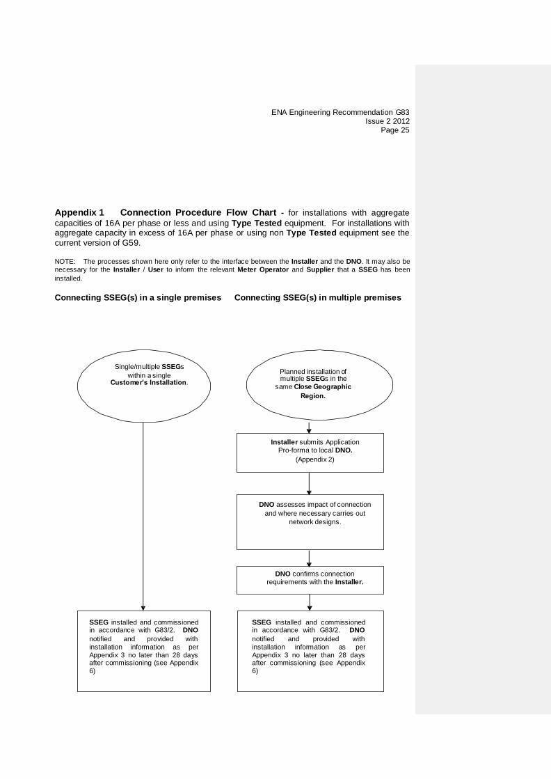
Appendix 1 Connection Procedure Flow Chart - for installations with aggregate capacities of 16A per phase or less and using Type Tested equipment. For installations with aggregate capacity in excess of 16A per phase or using non Type Tested equipment see the current version of G59. NOTE: The processes shown here only refer to the interface between the Installer and the DNO. It may also be necessary for the Installer / User to inform the relevant Meter Operator and Supplier that a SSEG has been installed. Connecting SSEG(s) in a single premises Connecting SSEG(s) in multiple premises
Single/multiple SSEGs within single
Planned installation multiple SSEGs in
same Close
Installer submits Application Pro-forma to local DNO.
(Appendix 2)
DNO assesses impact of connection and where necessary carries out
network designs.
DNO confirms connection requirements with the Installer.
SSEG installed and commissioned in accordance with G83/2. DNO notified and provided with installation information as per Appendix 3 no later than 28 days after commissioning (see Appendix 6)
SSEG installed and commissioned in accordance with G83/2. DNO notified and provided with installation information as per Appendix 3 no later than 28 days after commissioning (see Appendix 6)

ENA Engineering Recommendation G83 Issue 2 2012 Page 26
Appendix 2 Application for Connection
SSEG Application for connection of multiple G83/2 installations To ABC electricity distribution DNO or IDNO 99 West St, Imaginary Town, ZZ99 9AA [email protected] Installer Details
Installer
Accreditation/Qualification:
Address
Post Code
Contact person
Telephone Number
E-mail address Proposed SSEG Details.
Address Post Code
MPAN SSEG installed capacity in kW at 230V AC
Type Testing Ref No
PH1 PH2 PH3
Use continuation sheet where more than 10 SSEGs are to be installed. Please include an electronic map with the location of each property highlighted in red. Record SSEG capacities, in rated output kW at 230V AC, to one decimal place, under PH1 for single phase supplies and under the relevant phase for two and three phase supplies. For example 2.8kW Detail on a separate sheet if there are any proposals to limit export to a lower figure than that of the SSEG.

ENA Engineering Recommendation G83 Issue 2 2012
Page 27
Appendix 3 SSEG Installation Commissioning Confirmation
G83/2 SSEG INSTALLATION COMMISSIONING CONFIRMATION In accordance with ESQCR and HSE Certificate of Exemption (2008) (see Appendix 6) the Installer is required to advise the DNO of the intention to use the SSEG in parallel with the network no later than 28 days (inclusive of the day of commissioning), after commissioning the SSEG To ABC electricity distribution DNO or IDNO 99 West St, Imaginary Town, ZZ99 9AA [email protected] SSEG installation address details Name of Customer at Site Customer contact telephone Site address
Post Code MPAN SSEG owner if different from above Name and Contact Address Including Post Code
Contact telephone number SSEG Details Note only technologies with Type Tested equipment can be installed under G83/2. Capacities phase 1
in kW phase 2 in kW
phase 3 in kW
Type test ref only for new installations
Primary energy source. Eg Wind, Solar PV, Hydro, Gas CHP.
New/Existing New/Existing New/Existing New/Existing The Maximum aggregate capacity of SSEGs installed in a single customer’s installation under G83/2 is 3.68kW per phase at 230V AC. Identify above new SSEG installations and existing installations at the site which have not been de-commissioned as of the date of this declaration. Use a separate line for new and existing installations and for different Primary Energy sources above. For installations above 3.68kW per phase the separate G59 process applies and the DNO needs to be consulted before any installation is undertaken. Use ph 1 column for single phase supply I confirm that the new SSEGs noted above has/have been installed and commissioned to comply with the requirements of G83/2 as required by The Distribution Code. I enclose a copy of the circuit diagram which has been left on site at the customers incoming meter location. Name Signed
Date
On behalf of Installer Accreditation / Qualification Installer address
Post code Contact person Telephone number E:mail address

ENA Engineering Recommendation G83 Issue 2 2012 Page 28
Appendix 4 Type Verification Test Report
Type Approval and manufacturer/supplier declaration of compliance with the requirements of Engineering Recommendation G83/2. SSEG Type reference number
SSEG Type
System Supplier name
Address
Tel
Fax
E:mail
Web site
Maximum rated capacity, use separate sheet if more than one connection option.
Connection Option kW single phase, single, split or three phase system
kW three phase
kW two phases in three phase system
kW two phases split phase system
SSEG manufacturer/supplier declaration. I certify on behalf of the company named above as a manufacturer/supplier of Small Scale Embedded Generators, that all products manufactured/supplied by the company with the above SSEG Type reference number will be manufactured and tested to ensure that they perform as stated in this Type Verification Test Report, prior to shipment to site and that no site modifications are required to ensure that the product meets all the requirements of G83/2. Signed
On behalf of
Note that testing can be done by the manufacturer of an individual component, by an external test house, or by the supplier of the complete system, or any combination of them as appropriate. Where parts of the testing are carried out by persons or organisations other than the supplier then the supplier shall keep copies of all test records and results supplied to them to verify that the testing has been carried out by people with sufficient technical competency to carry out the tests.

ENA Engineering Recommendation G83 Issue 2 2012
Page 29
Power Quality. Harmonics. The requirement is specified in section 5.4.1, test procedure in Annex A or B 1.4.1
SSEG rating per phase (rpp)
kW NV=MV*3.68/rpp
Harmonic At 45-55% of rated output
100% of rated output
Measured Value (MV) in Amps
Normalised Value (NV) in Amps
Measured Value (MV) in Amps
Normalised Value (NV) in Amps
Limit in BS EN 61000-3-2 in Amps
Higher limit for odd harmonics 21 and above
2
1.080
3
2.300
4
0.430
5
1.140
6
0.300
7
0.770
8
0.230
9
0.400
10
0.184
11
0.330
12
0.153
13
0.210
14
0.131
15
0.150
16
0.115
17
0.132
18 0.102
19
0.118
20
0.092
21
0.107
0.160

ENA Engineering Recommendation G83 Issue 2 2012 Page 30
22
0.084
23
0.098
0.147
24
0.077
25
0.090
0.135
26
0.071
27
0.083
0.124
28
0.066
29
0.078
0.117
30
0.061
31
0.073
0.109
32
0.058
33
0.068
0.102
34
0.054
35
0.064
0.096
36
0.051
37
0.061
0.091
38
0.048
39
0.058
0.087
40
0.046
Note the higher limits for odd harmonics 21 and above are only allowable under certain conditions, if these higher limits are utilised please state the exemption used as detailed in part 6.2.3.4 of BS EN 61000-3-2 in the box below.

ENA Engineering Recommendation G83 Issue 2 2012
Page 31
Power Quality. Voltage fluctuations and Flicker. The requirement is specified in section 5.4.2, test procedure in Annex A or B 1.4.3 Starting Stopping Running dmax dc d(t) dmax dc
d(t) Pst Plt 2 hours
Measured Values
Normalised to standard impedance and 3.68kW for multiple units
Limits set under BS EN 61000-3-2
4% 3.3% 3.3% 500ms
4% 3.3% 3.3% 500ms
1.0 0.65
Test start date
Test end date
Test location
Power quality. DC injection. The requirement is specified in section 5.5, test procedure in Annex A or B 1.4.4 Test power level
10% 55% 100%
Recorded value
as % of rated AC current
Limit
0.25% 0.25% 0.25%
Power Quality. Power factor. The requirement is specified in section 5.6, test procedure in Annex A or B 1.4.2 216.2V
230V 253V Measured at three voltage levels and at
full output. Voltage to be maintained within ±1.5% of the stated level during the test.
Measured value
Limit >0.95
>0.95 >0.95

ENA Engineering Recommendation G83 Issue 2 2012 Page 32
Protection. Frequency tests The requirement is specified in section 5.3.1, test procedure in Annex A or B 1.3.3 Function Setting Trip test “No trip tests” Frequency Time
delay Frequency Time
delay Frequency /time
Confirm no trip
U/F stage 1
47.5Hz 20s 47.7Hz 25s
U/F stage 2
47Hz 0.5s 47.2Hz 19.98s
46.8Hz 0.48s
O/F stage 1
51.5Hz 90s 51.3Hz 95s
O/F stage 2
52Hz 0.5s 51.8Hz 89.98s
52.2Hz 0.48s
Protection. Voltage tests The requirement is specified in section 5.3.1, test procedure in Annex A or B 1.3.2 Function Setting Trip test “No trip tests” Voltage Time
delay Voltage Time
delay Voltage /time
Confirm no trip
U/V stage 1
200.1V 2.5s 204.1V 3.5s
U/V stage 2
184V 0.5s 188V 2.48s
180V 0.48s
O/V stage 1
262.2V 1.0s 258.2V 2.0s
O/V stage 2
273.7V 0.5s 269.7V 0.98s
277.7V 0.48s
Note for Voltage tests the Voltage required to trip is the setting ±3.45V. The time delay can be measured at a larger deviation than the minimum required to operate the protection. The No trip tests need to be carried out at the setting ±4V and for the relevant times as shown in the table above to ensure that the protection will not trip in error.
ENA Engineering Recommendation G83 Issue 2 2012
Page 33
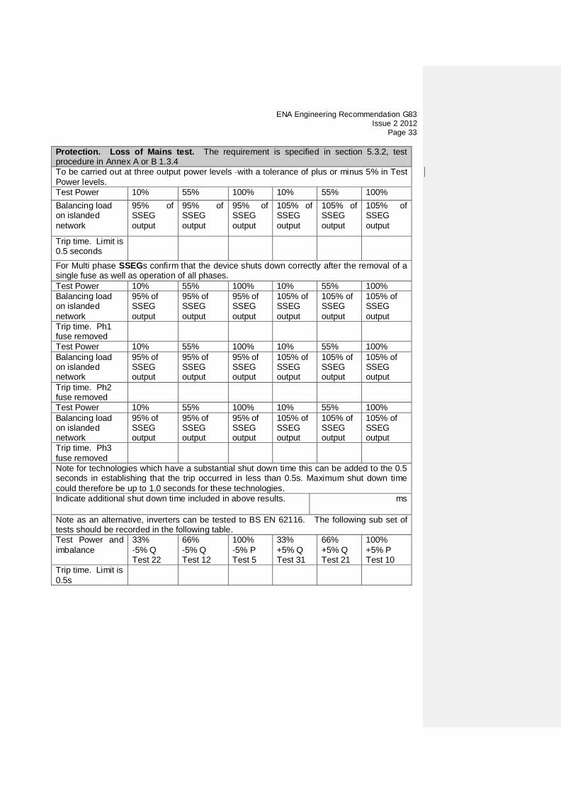
Protection. Loss of Mains test. The requirement is specified in section 5.3.2, test procedure in Annex A or B 1.3.4 To be carried out at three output power levels with a tolerance of plus or minus 5% in Test Power levels. Test Power 10% 55% 100% 10% 55% 100% Balancing load on islanded network
95% of SSEG output
95% of SSEG output
95% of SSEG output
105% of SSEG output
105% of SSEG output
105% of SSEG output
Trip time. Limit is 0.5 seconds
For Multi phase SSEGs confirm that the device shuts down correctly after the removal of a single fuse as well as operation of all phases. Test Power 10% 55% 100% 10% 55% 100% Balancing load on islanded network
95% of SSEG output
95% of SSEG output
95% of SSEG output
105% of SSEG output
105% of SSEG output
105% of SSEG output
Trip time. Ph1 fuse removed
Test Power 10% 55% 100% 10% 55% 100% Balancing load on islanded network
95% of SSEG output
95% of SSEG output
95% of SSEG output
105% of SSEG output
105% of SSEG output
105% of SSEG output
Trip time. Ph2 fuse removed
Test Power 10% 55% 100% 10% 55% 100% Balancing load on islanded network
95% of SSEG output
95% of SSEG output
95% of SSEG output
105% of SSEG output
105% of SSEG output
105% of SSEG output
Trip time. Ph3 fuse removed
Note for technologies which have a substantial shut down time this can be added to the 0.5 seconds in establishing that the trip occurred in less than 0.5s. Maximum shut down time could therefore be up to 1.0 seconds for these technologies. Indicate additional shut down time included in above results. ms
Note as an alternative, inverters can be tested to BS EN 62116. The following sub set of tests should be recorded in the following table. Test Power and imbalance
33% -5% Q Test 22
66% -5% Q Test 12
100% -5% P Test 5
33% +5% Q Test 31
66% +5% Q Test 21
100% +5% P Test 10
Trip time. Limit is 0.5s

ENA Engineering Recommendation G83 Issue 2 2012 Page 34
Protection. Frequency change, Vector Shift Stability test The requirement is specified in section 5.3.3, test procedure in Annex A or B 1.3.6 Start
Frequency Change End
Frequency Confirm no trip
Positive Vector Shift
49.5Hz +9 50 degrees
Negative Vector Shift
50.5Hz - 950 degrees
Positive Frequency drift
49.5Hz +0.19Hz/sec 51.5Hz
Negative Frequency drift
50.5Hz -0.19Hz/sec 47.5Hz
Protection. Frequency change, RoCoF Stability test The requirement is specified in section 5.3.3, test procedure in Annex A or B 1.3.6 Ramp range Test frequency ramp: Test
Duration Confirm no trip
49.0Hz to 51.0Hz +0.95Hzs-1 2.1s
51.0Hz to 49.0Hz -0.95Hzs-1 2.1s Protection. Re-connection timer. The requirement is specified in section 5.3.4, test procedure in Annex A or B 1.3.5 Test should prove that the reconnection sequence starts after a minimum delay of 20 seconds for restoration of voltage and frequency to within the stage 1 settings of table 1. Time delay setting
Measured delay
Checks on no reconnection when voltage or frequency is brought to just outside stage 1 limits of table 1.
At 266.2V At 196.1V At 47.4Hz At 51.6Hz Confirmation that the SSEG does not re-connect.
Fault level contribution. The requirement is specified in section 5.7, test procedure in Annex A or B 1.4.6 For a directly coupled SSEG For a Inverter SSEG
Parameter Symbol Value Time after fault
Volts Amps
Peak Short Circuit current
i p 20ms
Initial Value of aperiodic current
A 100ms
Initial symmetrical short-circuit current*
Ik 250ms
Decaying (aperiodic) component of short circuit current*
iDC 500ms
Reactance/Resistance X/R Time to In seconds
Formatted: Space Before: 4 pt, After: 4 pt
Formatted: Font: 11 pt
Formatted: Space Before: 4 pt, After: 4 pt
Formatted: Font: 11 pt
Formatted: Font: 11 pt
Formatted: Font: 11 pt
Formatted: Space Before: 4 pt, After: 4 pt
Formatted: Superscript

ENA Engineering Recommendation G83 Issue 2 2012
Page 35
Ratio of source* trip Self-Monitoring solid state switching The requirement is specified in section 5.3.1, No specified test requirements.
Yes/or NA
It has been verified that in the event of the solid state switching device failing to disconnect the SSEG, the voltage on the output side of the switching device is reduced to a value below 50 volts within 0.5 seconds.
Additional comments

ENA Engineering Recommendation G83 Issue 2 2012 Page 36
Appendix 5 SSEG Decommissioning Confirmation
G83/2 SSEG DECOMMISSIONING CONFIRMATION
SSEG de-commissioning form and declaration, to be provided to the DNO by the installer no later than 28 days after de-commissioning all, or some of the SSEGs in a Customer’s Installation. To ABC electricity distribution DNO or IDNO 99 West St, Imaginary Town, ZZ99 9AA [email protected] Electricity Customer at site Customer contact telephone SSEG Site address
Post Code MPAN SSEG owner if different from above
Contact Address
Contact telephone number Details of installation Removed type
Capacity ph 1 kW
Capacity ph 2 kW
Capacity ph 3 kW
Remaining type
Capacity ph 1 kW
Capacity ph 2 kW
Capacity ph 3 kW
I confirm that the SSEG installation noted above has been modified or totally de-commissioned and continues to comply with the requirements of G83/2 as required by the distribution code of Great Britain. I enclose a copy of the system schematic which has been left on site at the customers incoming meter location. Name Signed
Date
On behalf of Installer Accreditation / Qualification Installer address
Post code Contact person Telephone number E:mail address
ENA Engineering Recommendation G83 Issue 2 2012
Page 37
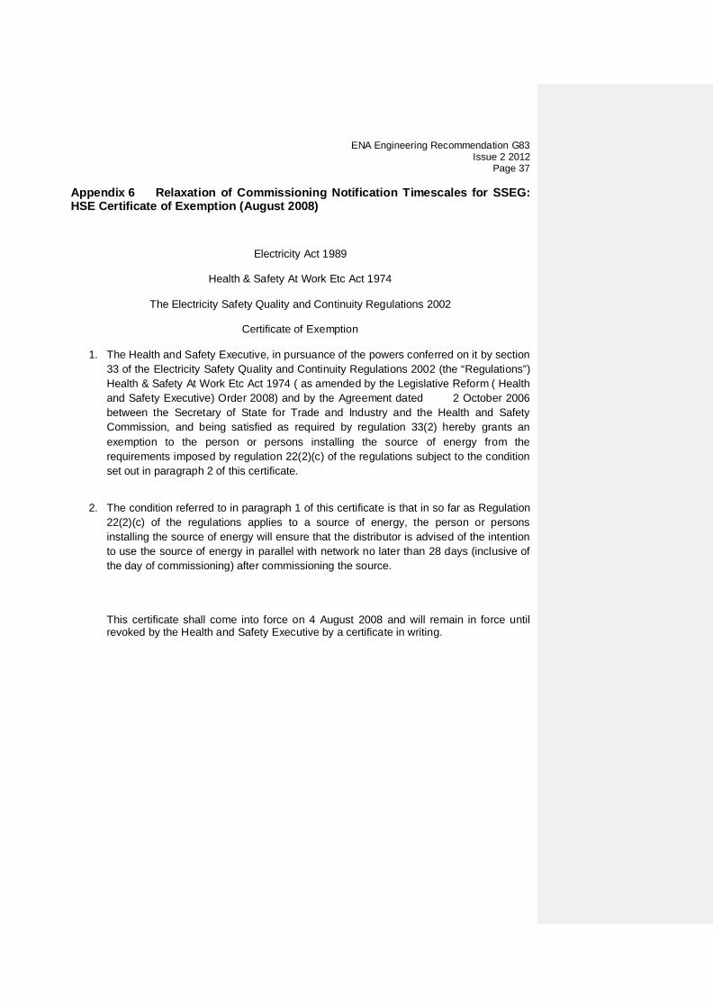
Appendix 6 Relaxation of Commissioning Notification Timescales for SSEG: HSE Certificate of Exemption (August 2008)
Electricity Act 1989
Health & Safety At Work Etc Act 1974
The Electricity Safety Quality and Continuity Regulations 2002
Certificate of Exemption
1. The Health and Safety Executive, in pursuance of the powers conferred on it by section 33 of the Electricity Safety Quality and Continuity Regulations 2002 (the “Regulations”) Health & Safety At Work Etc Act 1974 ( as amended by the Legislative Reform ( Health and Safety Executive) Order 2008) and by the Agreement dated 2 October 2006 between the Secretary of State for Trade and Industry and the Health and Safety Commission, and being satisfied as required by regulation 33(2) hereby grants an exemption to the person or persons installing the source of energy from the requirements imposed by regulation 22(2)(c) of the regulations subject to the condition set out in paragraph 2 of this certificate.
2. The condition referred to in paragraph 1 of this certificate is that in so far as Regulation
22(2)(c) of the regulations applies to a source of energy, the person or persons installing the source of energy will ensure that the distributor is advised of the intention to use the source of energy in parallel with network no later than 28 days (inclusive of the day of commissioning) after commissioning the source.
This certificate shall come into force on 4 August 2008 and will remain in force until revoked by the Health and Safety Executive by a certificate in writing.

ENA Engineering Recommendation G83 Issue 2 2012 Page 38
Annex A-C Guidance on Type Testing Requirements
Annex A Common Inverter Requirements. Annex B Common Directly Coupled Requirements. Annex C Separate Specific Technology Requirements.
• C1. Domestic CHP • C2. Photo-voltaic • C3. Fuel Cells • C4. Hydro • C5. Wind • C6. Energy Storage Devices
An SSEG requiring type testing must be Type Tested in relation to its grid connection type and its energy source technology.
Annex A relates to any SSEG that uses an Inverter (or Converter) as its means of connecting to the grid.
Annex B relates to any SSEG that during normal running operation is connected directly to the grid.
When type testing any SSEG you must select either Annex A or Annex B as is most appropriate to the grid connect method relating to the SSEG under test. The SSEG may also require additional technology specific type tests as identified in Annex C, this annex relates to the Technology relating to the energy source. Examples A Wind Turbine system using an Inverter (or Inverters) for connection is required to type test using Annex A – “Common Inverter Requirements” and Annex C5 – “Wind” Separate Specific Technology Requirements”. A Hydro system using an induction motor connected directly to the grid is required to be Type Tested using Annex B – “Directly Coupled Requirements” and Annex C4– “Hydro” of Annex C - “Separate Specific Technology Requirements”.

ENA Engineering Recommendation G83 Issue 2 2012
Page 39
Annex A1 Common Inverter Connected SSEG Requirements A1.1 Certification & Type Testing SSEG Requirements This Annex describes a methodology for obtaining type certification or type verification for the interface equipment between the Inverter connected SSEG and the distribution network. Typically, all interface functions are contained within the Inverter and in such cases it is only necessary to have the Inverter Type Tested. Alternatively, a package of specific separate parts of equivalent function may also be Type Tested.
Other Annexes containing Inverter connected equipment may make reference to the requirements specified in this Annex.
This Annex applies for SSEG systems either with or without load management or energy storage systems which connected on the generator side of the Inverter.
A1.2 CE Marking and Certification The type verification procedure requires that the SSEG interface be certified to the relevant requirements of the applicable Directives before the unit can be labelled with a CE mark. Where the protection control is to be provided as a separate device, this must also be Type Tested and certified to the relevant requirements of the applicable Directives before it can be labelled with a CE mark. Currently there are no harmonised functional standards that apply to the SSEG Interface Protection, therefore the Inverter and any separate Interface Protection unit will require functional Type Tested as described in this Annex, and recorded in format similar to that shown in Appendix 4.
A1.3 Type Verification Functional Testing of the Interface Protection Type Testing is the responsibility of the Manufacturer. This test will verify that the operation of the SSEG Interface Protection shall result:
a) in the safe disconnection of the SSEG from the DNO’s Distribution System in the event that the protection settings specified in table 1 are exceeded; and
b) in the SSEG remaining connected to the DNO’s Distribution System while network conditions are:
a. within the envelope specified by the settings plus and minus the tolerances specified for equipment operation in table 1; and
b. within the trip delay settings specified in table 1.
The Type Testing can be done by the Manufacturer of an individual component, by an external test house, or by the supplier of the complete system, or any combination of them as appropriate. Wherever possible the Type Testing of an Inverter designed for a particular type of SSEG should be proved under normal conditions of operation for that technology (unless otherwise noted).
This will require that the chosen SSEG Interface Protection is either already incorporated into the Inverter or that the discrete device is connected to the Inverter for the loss of mains protection test. Testing the voltage and frequency functions may be carried out on the
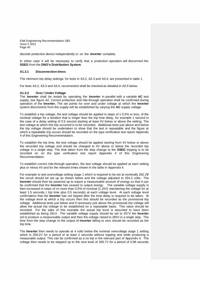
ENA Engineering Recommendation G83 Issue 2 2012 Page 40
discrete protection device independently or on the Inverter complete.
In either case it will be necessary to verify that a protection operation will disconnect the SSEG from the DNO’s Distribution System.
A1.3.1 Disconnection times The minimum trip delay settings, for tests in A3.2, A3.3 and A3.4, are presented in table 1. For tests A3.2, A3.3 and A3.4, reconnection shall be checked as detailed in A3.5 below.
A1.3.2 Over / Under Voltage The Inverter shall be tested by operating the Inverter in parallel with a variable AC test supply, see figure A2. Correct protection and ride-through operation shall be confirmed during operation of the Inverter. The set points for over and under voltage at which the Inverter system disconnects from the supply will be established by varying the AC supply voltage.
To establish a trip voltage, the test voltage should be applied in steps of ± 0.5% or less, of the nominal voltage for a duration that is longer than the trip time delay, for example 1 second in the case of a delay setting of 0.5 second starting at least 4V below or above the setting. The test voltage at which this trip occurred is to be recorded. Additional tests just above and below the trip voltage should be undertaken to show that the test is repeatable and the figure at which a repeatable trip occurs should be recorded on the type verification test report Appendix 4 of this Engineering Recommendation.
To establish the trip time, the test voltage should be applied starting from 4V below or above the recorded trip voltage and should be changed to 4V above or below the recorded trip voltage in a single step. The time taken from the step change to the SSEG tripping is to be recorded on on the type verification test report Appendix 4 of this Engineering Recommendation. To establish correct ride-through operation, the test voltage should be applied at each setting plus or minus 4V and for the relevant times shown in the table in Appendix 4. For example to test overvoltage setting stage 1 which is required to be set at nominally 262.2V the circuit should be set up as shown below and the voltage adjusted to 254.2 volts. The Inverter should then be powered up to export a measureable amount of energy so that it can be confirmed that the Inverter has ceased to output energy. The variable voltage supply is then increased in steps of no more than 0.5% of nominal (1.15V) maintaining the voltage for at least 1.5 seconds ( trip time plus 0.5 seconds) at each voltage level. At each voltage level confirmation that the Inverter has not tripped after the time delay is required to be taken. At the voltage level at which a trip occurs then this should be recorded as the provisional trip voltage. Additional tests just below and if necessary just above the provisional trip voltage will allow the actual trip voltage to be established on a repeatable basis. This value should be recorded. For the sake of this example the actual trip level is assumed to have been established as being 261V. The variable voltage supply should be set to 257V the Inverter set to produce a measureable output and then the voltage raised to 265V in a single step. The time from the step change to the output of Inverter falling to zero should be recorded as the trip time. The Inverter then needs to operate at 4 volts below the nominal overvoltage stage 1 setting which is 258.2V for a period of at least 2 seconds without tripping and while producing a measurable output. This can be confirmed as a no trip in the relevant part of Appendix 4. The voltage then needs to be stepped up to the next level of 269.7V for a period of 0.98 seconds

ENA Engineering Recommendation G83 Issue 2 2012
Page 41
and then back to 258.2V during which time the output of the relay should continue with no interruption though it may change due to the change in voltage, this can be recorded as a no trip for the second value. The step up and step down test needs to be done a second time with a max value of 277.7V and with a time of 0.48 seconds. The Inverter is allowed to shut down during this period to protect its self as allowed by note 2 of Table 1 of this document, but it must resume production again when the voltage has been restored to 258.2V or it may continue to produce an output during this period. There is no defined time for resumption of production but it must be shown that restart timer has not operated so it must begin producing again in less than 20 seconds. Note that this philosophy should be applied to the under voltage, over and under frequency, RoCoF and Vector shift stability tests which follow. Note: (1) The frequency required to trip is the setting plus or minus 0.1Hz (2) Measurement of operating time should be measured at a value of 0.2Hz (suggestion – 2 x tolerance) above/below the setting to give “positive” operation (3) The “No trip tests” need to be carried out at the relevant values and times as shown in the table above to ensure that the protection will not trip in error. Figure A2. SSEG Test set up – Over / Under Voltage
A1.3.3 Over / Under Frequency The Inverter shall be tested by operating the Inverter in parallel with a low impedance, variable frequency test supply system, see figure A3. Correct protection and ride-through operation should be confirmed during operation of the Inverter. The set points for over and under frequency at which the Inverter system disconnects from the supply will be established by varying the test supply frequency. To establish a trip frequency, the test frequency should be applied in a slow ramp rate of less than 0.1Hz/second, or if this is not possible in steps of 0.05Hz for a duration that is longer than the trip time delay, for example 1 second in the case of a delay setting of 0.5 second. The test frequency at which this trip occurred is to be recorded. Additional tests just above and below the trip frequency should be undertaken to show that the test is repeatable and the figure at which a repeatable trip occurs should be recorded on the type verification test report Appendix 4 of this Engineering Recommendation.
To establish the trip time, the test frequency should be applied starting from 0.3Hz below or above the recorded trip frequency and should be changed to 0.3Hz above or below the recorded trip frequency in a single step. The time taken from the step change to the SSEG tripping is to be recorded on the type verification test report Appendix 4 of this Engineering Recommendation. It should be noted that with some loss of mains detection techniques this test may result in a faster trip due to operation of the loss of mains protection. There are two ways around this. Firstly the loss of mains protection may be able to be turned off in order to carry out this test. Secondly by establishing an accurate frequency for the trip a much smaller
SSEG SSEG or Simulator
Inverter Variable AC Voltage Test
Supply

ENA Engineering Recommendation G83 Issue 2 2012 Page 42
step change could be used to initiate the trip and establish a trip time. This may require the test to be repeated several times to establish that the time delay is correct.
To establish correct ride-through operation, the test frequency should be applied at each setting plus or minus 0.2Hz and for the relevant times shown in the table in Appendix 4.
Figure A3 SSEG Test set up – Over / Under Frequency
A1.3.4 Loss of Mains Protection The tests should be carried out in accordance with BS EN 62116 and a subset of results should be recorded as indicated in the Protection – Loss of Mains test section of Annex 4 Type Test Verification Report.
. A1.3.5 Re-connection Further tests will be carried out with the three test circuits above to check the Inverter time out feature prior to automatic network reconnection. This test will confirm that once the AC supply voltage and frequency have returned to be within the stage 1 settings specified in table 1 following an automatic protection trip operation there is a minimum time delay of 20 seconds before the Inverter output is restored (ie before the Inverter automatically reconnects to the network). A1.3.6 Frequency Drift and Step Change Stability test. The tests will be carried out using the same circuit as specified in A1.3.3 above and following confirmation that the SSEG has passed the under and over frequency trip tests and the under and over frequency stability tests. Four tests are required to be carried out with all protection functions enabled including loss of mains. For each stability test the SSEG should not trip during the test. For the step change test the SSEG should be operated with a measureablemeasurable output at the start frequency and then a vector shift should be applied by extending or reducing the time of a single cycle with subsequent cycles returning to the start frequency. The start frequency should then be maintained for a period of at least 10 seconds to complete the test. The SSEG should not trip during this test. For frequency drift tests the SSEG should be operated with a measureablemeasurable output at the start frequency and then the frequency changed in a ramp function at 0.19Hz 95Hz per second to the end frequency. On reaching the end frequency it should be maintained for a period of at least 10 seconds. The SSEG should not trip during this test.
SSEG SSEG or Simulator
Inverter Variable Frequency Test Supply

ENA Engineering Recommendation G83 Issue 2 2012
Page 43
A1.4 POWER QUALITY
A1.4.1 Harmonics
The tests should be carried out as specified in BS EN 61000-3-2 and can be undertaken with a fixed source of energy at two power levels firstly between 45 and 55% and at 100% of maximum export capacity. A1.4.2 Power Factor The test set up shall be such that the Inverter supplies full load to the DNO’s Distribution System via the power factor (pf) meter and the variac as shown below in figure A5. The Inverter pf should be within the limits given in 5.6, for three test voltages 230 V –6%, 230V and 230 V +10%.
Figure A5 SSEG Test set up – Power Factor
NOTE 1 For reasons of clarity the points of isolation are not shown. NOTE 2: It is permissible to use a voltage regulator or tapped transformer to perform this
test rather than a variac as shown. A1.4.3 Voltage Flicker The voltage fluctuations and flicker emissions from the SSEG shall be measured in accordance with BS EN 61000-3-3 and technology specific annex. A1.4.4 DC Injection The level of DC injection from the Inverter-connected PV generator in to the DNO’s Distribution System shall not exceed the levels specified in 5.5 when measured during operation at three levels, 10%, 55% and 100% of rating with a tolerance of plus or minus 5%. The DC injection requirements can be satisfied by the installation of an isolation transformer on the AC side of an Inverter-connected SSEG. A declaration that an isolating transformer is fitted can be made in lieu of the tests noted above. A1.4.5 Overcurrent Protection Where appropriate the protection shall comply with the requirements of BS7671. A1.4.6 Short Circuit Current Contribution Inverter connected SSEG’s generally have small short circuit fault contributions however DNO’s need to understand the contribution that they do make to system fault levels in order to determine that they can continue to safely operate without exceeding design fault levels for switchgear and other circuit components.
SSEG SSEG or Simulator
Inverter DNO’s Distribution
System Variac p
f
Formatted: Right: 0.05 cm, Keepwith next

ENA Engineering Recommendation G83 Issue 2 2012 Page 44
The following type tests shall be carried out and the results noted in Appendix 4. Test circuit
Test procedure ‘A’ and ‘V’ are ammeters and voltmeters used to record the test data required. Component ‘D’ is a resistive load plus resonant circuit as required for the loss of mains test as specified in BS EN 62116 set up to absorb 100% rated output of the Inverter. Component ‘a’ is an ammeter used to confirm that all the output from the Inverter is being absorbed by component D. Components ‘B’ and ‘C’ are set up to provide a voltage of between 10% and 40% of nominal when component ‘C’ carries the rated output of the Inverter in Amps. Component ‘C’ should be short term rated to carry the load which would appear through it should it be energised at 253V for at least 1s. Component ‘B’ is to have an impedance of between 10 and 20 ohms per phase. If components ‘B’ and ‘C’ are short time rated than an additional switch in series with ‘B’ and ‘C’ can be inserted and arranged to be closed shortly before the main change over switch shown on the drawing and opened at the end of the test period. Components ‘B’ and ‘C’ are to have an X to R ratio of 2.5 to 1. The test is carried out by setting up the Inverter and load ‘D’ to produce and then absorb full rated output of the Inverter. When zero export is shown by ammeter ‘a’ then the changeover switch shown is operated connecting the Inverter to the reduced voltage connection created by components ‘B’ and ‘C’ and disconnecting if from the normal connection. The make contact is an early make and the break contact a late break so that the inverter is not disconnected from a mains connection for any significant time. The values of voltage and current should be recorded for a period of up to 1 second when the changeover switch should be returned to the normal position. The voltage and current at relevant times shall be recorded in the type test report (Appendix 4) including the time taken for the Inverter to trip. (It is expected that the Inverter will trip on either loss of mains or under voltage in less than one second). A1.4.7 Self-Monitoring - Solid State Disconnection Some Inverters include solid state switching devices to disconnect from the DNO’s Distribution System. In this case 5.3.1 requires the control equipment to monitor the output stage of the Inverter to ensure that in the event of a protection initiated trip the output voltage is either disconnected completely or reduced to a value below 50 volts AC. This
B
C
D
a
Inverter
V
A 230v AC 50Hz
DC supply to suit inverter under test

ENA Engineering Recommendation G83 Issue 2 2012
Page 45
shall be verified either by self-certification by the Manufacturer, or additional material shall be presented to the tester sufficient to allow an assessment to be made.
A1.4.8 Electromagnetic Compatibility (EMC ) All equipment shall comply with the generic EMC standards: BS EN61000-6-3: 2007 Electromagnetic Compatibility, Generic Emission Standard; and BS EN61000-6-1: 2007 Electromagnetic Compatibility, Generic Immunity Standard.

ENA Engineering Recommendation G83 Issue 2 2012 Page 46
Annex B1 Common Directly Coupled Connected SSEG Requirements B1.1 Certification & Type Testing General Requirements This Annex describes a methodology for obtaining type certification or type verification for the interface equipment between a directly coupled SSEG and the distribution network. Interface functions can be provided by either as an integrated part of the controller or by incorporating a Type Tested protection relay.
Other Annexes containing directly coupled equipment may make reference to the requirements specified in this Annex.
This Annex applies for SSEG systems either with or without load management or energy storage systems which connected on the generator side of the controller. B1.2 CE Marking & Certification The type verification procedure requires that the SSEG interface be certified to the relevant requirements of the applicable Directives before the unit can be labelled with a CE mark. Where the protection control is to be provided as a separate device, this must also be Type Tested and certified to the relevant requirements of the applicable Directives before it can be labelled with a CE mark. Currently there are no harmonised functional standards that apply to the SSEG Interface Protection, therefore the Controller and any separate Interface Protection unit will require the functionality to be Type Tested as described in this Annex, and recorded in format similar to that shown in Appendix 4.
B1.3 Type Verification Functional Testing of the Interface Protection Type verification testing is the responsibility of the Manufacturer. This test will verify that the operation of the SSEG Interface Protection shall result:
a) in the safe disconnection of the SSEG from the DNO’s Distribution System in the event that the protection settings specified in table 1 are exceeded; and
b) in the SSEG remaining connected to the DNO’s Distribution System while network conditions are:
a. within the envelope specified by the settings plus and minus the tolerances specified for equipment operation in table 1; and
b. within the trip delay settings specified in table 1.
The testing can be done by the Manufacturer of an individual component, by an external test house, or by the supplier of the complete system, or any combination of them as appropriate. Wherever possible the type verification testing of the SSEG control system should be proved under normal conditions of operation for that technology (unless otherwise noted).
This will require that the chosen SSEG Interface Protection is either already incorporated into the Controller or that the discrete device is connected to the Controller for the loss of mains protection test. Testing the voltage and frequency functions may be carried out on the discrete protection device independently or as part of the Controller. In either case it will be necessary to verify that a protection operation will disconnect the SSEG from the DNO’s Distribution System The Manufacturer must declare the ambient operating temperature range of the SSEG, and

ENA Engineering Recommendation G83 Issue 2 2012
Page 47
verify that the Interface Protection will operate satisfactorily throughout this temperature range.
B1.3.1 Disconnection times The minimum trip delay settings, for tests in B3.2, B3.3 and B3.4, are presented in table 1. For tests B3.2, B3.3 and B3.4, reconnection shall be checked as detailed in 5.3.4 as a mechanical based system.
In some systems it may be safer and more convenient to test the trip delay time and the disconnection time separately. This will allow the trip delay time to be measured in a test environment (in a similar way as you could test a protection relay). The disconnection time can be measured in the SSEG’s normal operation, allowing accurate measurement with correct inertia and prime mover characteristics. This is permitted providing the total disconnection time does not exceed the value specified in section 5.3.1. When measuring the shutdown time, 5 shutdowns should be initiated, and the average time recorded. B1.3.2 Over / Under Voltage The Controller shall be tested by operating the Controller in parallel with a variable AC test supply, see figure B2. Correct protection and ride-through operation shall be confirmed. The set points for over and under voltage at which the Controller disconnects from the supply, will be established by varying the AC supply voltage. The disconnect sequence should be initiated when the conditions of table 1 are met, otherwise normal operation should continue.
To establish the certified trip voltage, the test voltage should be applied in steps of ± 0.5% of setting for a duration that is longer than the trip time delay, for example 1 second in the case of a delay setting of 0.5 second. It will be necessary to carry out five tests for each trip setting. The test voltage at which this trip occurred is to be recorded as the certified trip voltage.
To establish the certified trip time, the test voltage should be applied starting from ± 4V below the certified trip voltage in a step of at least ± 0.5% of setting for a duration that is longer than the trip time delay, for example 1 second in the case of a delay setting of 0.5 second. It will be necessary to carry out five tests for each trip setting. The longest trip time is to be recorded as the certified trip time. For example to test overvoltage setting stage 1 which is required to be set at nominally 262.2V the circuit should be set up as shown below and the voltage adjusted to 254.2 volts. The Inverter should then be powered up to export a measureablemeasurable amount of energy so that it can be confirmed that the Inverter has ceased to output energy. The variable voltage supply is then increased in steps of no more than 0.5% of nominal (1.15V) maintaining the voltage for at least 1.5 seconds ( trip time plus 0.5 seconds) at each voltage level. At each voltage level confirmation that the Inverter has not tripped after the time delay is required to be taken. At the voltage level at which a trip occurs then this should be recorded as the provisional trip voltage. Additional tests just below and if necessary just above the provisional trip voltage will allow the actual trip voltage to be established on a repeatable basis. This value should be recorded. For the sake of this example the actual trip level is assumed to have been established as being 261V. The variable voltage supply should be set to 257V the Inverter set to produce a measureablemeasurable output and then the voltage raised to 265V in a single step. The time from the step change to the output of Inverter falling to zero should be recorded as the trip time.

ENA Engineering Recommendation G83 Issue 2 2012 Page 48
To establish correct ride-through operation, the test voltage should be applied at each setting plus or minus 4V and for the relevant times shown in the table in Appendix 4.
Test results should be recorded on the Test Sheet shown in Appendix 4.
Figure B2.-SSEG Test set up – Over / Under Voltage
B1.3.3 Over / Under Frequency The protection shall be tested by operating the SSEG in parallel with a low impedance, variable frequency test supply system, see figure B3. Correct protection and ride-through operation should be confirmed during operation of the SSEG. The set points for over and under frequency at which the SSEG system disconnects from the supply will be established by varying the test supply frequency. To establish a trip frequency, the test frequency should be applied in a slow ramp rate of less than 0.1Hz/second, or if this is not possible in steps of 0.05Hz for a duration that is longer than the trip time delay, for example 1 second in the case of a delay setting of 0.5 second. The test frequency at which this trip occurred is to be recorded. Additional tests just above and below the trip frequency should be undertaken to show that the test is repeatable and the figure at which a repeatable trip occurs should be recorded on the type verification test report Appendix 4 of this Engineering Recommendation. To establish the trip time, the test frequency should be applied starting from 0.3Hz below or above the recorded trip frequency and should be changed to 0.3Hz above or below the recorded trip frequency in a single step. The time taken from the step change to the SSEG tripping is to be recorded on the type verification test report Appendix 4 of this Engineering Recommendation. It should be noted that with some loss of mains detection techniques this test may result in a faster trip due to operation of the loss of mains protection. There are two ways around this. Firstly the loss of mains protection may be able to be turned off in order to carry out this test. Secondly by establishing an accurate frequency for the trip a much smaller step change could be used to initiate the trip and establish a trip time. This may require the test to be repeated several times to establish that the time delay is correct. To establish correct ride-through operation, the test frequency should be applied at each setting plus or minus 0.2Hz and for the relevant times shown in the table in Appendix 4.
SSEG Generator Controller Variable AC
Voltage Test Supply

ENA Engineering Recommendation G83 Issue 2 2012
Page 49
Figure B3. SSEG Test set up – Over / Under Frequency
B1.3.4 Loss of Mains Protection The resonant test circuit specif ied in this t est has been designed to model the interaction of the directly coupled SSEG under test with the local load including multiple directly coupled connected SSEGs in parallel. The directly coupled SSEG output shall be connected to a network combining a resonant circuit with a Q factor of >0.5 and a variable load. The value of the load is to match the directly coupled SSEG output. To facilitate the test for LoM there shall be a switch placed between the test load/directly coupled SSEG combination and the DNO’s Distribution System, as shown below: Figure B4 SSEG Test set up - Loss of Mains
The directly coupled SSEG is to be tested at three levels of the directly coupled SSEG’s output power: 10%, 55% and 100% and the results recorded on the test sheet of Appendix 4. For each test the load match is to be within ± 5%. Each test is to be repeated five times. Load match conditions are defined as being when the current from the directly coupled SSEG meets the requirements of the test load ie there is no export or import of supply frequency current to or from the DNO’s Distribution System. The tests will record the directly coupled SSEG’s output voltage and frequency from at least 2 cycles before the switch is opened until the protection system operates and disconnects itself from the DNO’s Distribution System, or for five seconds whichever is the lower duration. The time from the switch opening until the protection disconnection occurs is to be measured and must comply with the requirements in table 1.
SSEG Generator Controller Variable
Frequency Test Supply
SSEG Generator Controller
DNO’s Distribution
System
Resonant Circuit Q>0.5
at 50Hz
Variable Resistance
Load

ENA Engineering Recommendation G83 Issue 2 2012 Page 50
B1.3.5 Re-connection Further tests will be carried out with the three test circuits above to check the directly coupled SSEG time- out feature prior to automatic network reconnection. This test will confirm that once the AC supply voltage and frequency have returned to within the stage 1 settings specified in table 1 following an automatic protection trip operation there is a minimum time delay as specified in table 1 before reconnection will be allowed. B1.3.6 Frequency Drift and Step Change Stability test. The tests will be carried out using the same circuit as specified in B1.3.3 above and following confirmation that the SSEG has passed the under and over frequency trip tests and the under and over frequency stability tests. Four tests are required to be carried out with all protection functions enabled including loss of mains. For each stability test the SSEG should not trip during the test. For the step change test the SSEG should be operated with a measureablemeasurable output at the start frequency and then a vector shift should be applied by extending or reducing the time of a single cycle with subsequent cycles returning to the start frequency. The start frequency should then be maintained for a period of at least 10 seconds to complete the test. The SSEG should not trip during this test. For frequency drift tests the SSEG should be operated with a measureablemeasurable output at the start frequency and then the frequency changed in a ramp function at 0.19Hz 95Hz per second to the end frequency. On reaching the end frequency it should be maintained for a period of at least10 seconds. The SSEG should not trip during this test.
B1.4. POWER QUALITY
B1.4.1 Harmonics
The tests should be carried out as specified in BS EN 61000-3-2 and can be undertaken with a fixed source of energy at two power levels firstly between 45 and 55% and at 100% of maximum export capacity. B1.4.2 Power Factor The test set up shall be such that the directly coupled SSEG supplies full load to the DNO’s Distribution System via the power factor (pf) meter and the variac as shown below in figure B5. The directly coupled SSEG pf should be within the limits given in 5.6, for three test voltages 230 V –6%, 230V and 230 V +10%.
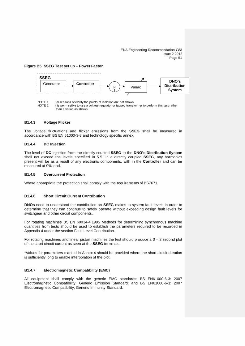
ENA Engineering Recommendation G83 Issue 2 2012
Page 51
Figure B5 SSEG Test set up – Power Factor
NOTE 1. For reasons of clarity the points of isolation are not shown NOTE 2: It is permissible to use a voltage regulator or tapped transformer to perform this test rather
than a variac as shown
B1.4.3 Voltage Flicker The voltage fluctuations and flicker emissions from the SSEG shall be measured in accordance with BS EN 61000-3-3 and technology specific annex.
B1.4.4 DC Injection The level of DC injection from the directly coupled SSEG to the DNO’s Distribution System shall not exceed the levels specified in 5.5. In a directly coupled SSEG, any harmonics present will be as a result of any electronic components, with in the Controller and can be measured at 0% load. B1.4.5 Overcurrent Protection Where appropriate the protection shall comply with the requirements of BS7671.
B1.4.6 Short Circuit Current Contribution
DNOs need to understand the contribution an SSEG makes to system fault levels in order to determine that they can continue to safely operate without exceeding design fault levels for switchgear and other circuit components.
For rotating machines BS EN 60034-4:1995 Methods for determining synchronous machine quantities from tests should be used to establish the parameters required to be recorded in Appendix 4 under the section Fault Level Contribution. For rotating machines and linear piston machines the test should produce a 0 – 2 second plot of the short circuit current as seen at the SSEG terminals. *Values for parameters marked in Annex 4 should be provided where the short circuit duration is sufficiently long to enable interpolation of the plot. B1.4.7 Electromagnetic Compatibility (EMC) All equipment shall comply with the generic EMC standards: BS EN61000-6-3: 2007 Electromagnetic Compatibility, Generic Emission Standard; and BS EN61000-6-1: 2007 Electromagnetic Compatibility, Generic Immunity Standard.
SSEG Generator Controller DNO’s
Distribution System
Variac pf

ENA Engineering Recommendation G83 Issue 2 2012 Page 52
Annex C1 Separate Specific SSEG Technology Requirements C1.1 Domestic CHP For Domestic CHP SSEGs connected to the DNO’s Distribution System via an Inverter, the type verification testing and Interface Protection requirements will be as per the requirements defined in Annex A.
For Domestic CHP SSEGs directly coupled to the DNO’s Distribution System, the type verification testing and Interface Protection requirements will be as per the requirements defined in Annex B. C1.2 Photovoltaic As all current Photovoltaic SSEGs will connect to the DNO’s Distribution System via an Inverter, the type verification testing and Interface Protection requirements will be as per the requirements defined in Annex A. C1.3 Fuel Cells As all current Fuel Cell SSEGs will connect to the DNO’s Distribution System via an Inverter, the type verification testing and Interface Protection requirements will be as per the requirements defined in Annex A. C1.4 Hydro Hydro can be connected to the DNO’s Distribution System directly using induction or synchronous generators or it can be connected by an Inverter. The common requirements for the generator technologies will apply to micro hydro in addition the following needs to be taken into consideration. SSEGs with manually fixed output or where the output is fixed by controlling the water flow through the turbine to a steady rate, need to comply with the maximum voltage change requirements of BS EN 61000-3-2 but do not need to be tested for Pst or Plt. SSEGs where the output is controlled by varying the load on the generator using the Inverter and which therefore produces variable output need to comply with the maximum voltage change requirements of BS EN 61000-3-2 and also need to be tested for Pst and Plt over a period where the range of flows varies over the design range of the turbine with a period of at least 2 hours at each step with there being 10 steps from min flow to maximum flow. Pst and Plt values to recorded and normalised as per the method laid down in Appendix 4. C1.5 Wind Wind turbines can be connected to the DNO’s Distribution System directly, typically using asynchronous induction generators, or using Inverters. For those connected via Inverters, the type verification testing and interface protection requirements shall be as specified in Annex A. For those connected directly to the DNO’s Distribution System, the type verification testing and interface protection requirements shall be as specified in Annex B.

ENA Engineering Recommendation G83 Issue 2 2012
Page 53
In addition, in either case, the note regarding wind turbine voltage flicker testing specified in 5.4 shall apply. C1.6 Energy Storage Device Energy Storage Devices can be connected to the DNO’s Distribution System directly or using Inverters. For those connected via Inverters, the type verification testing and interface protection requirements shall be as specified in Annex A. For those connected directly to the DNO’s Distribution System, the type verification testing and interface protection requirements shall be as specified in Annex B.