engineering model of liquid storage utility tank …/67531/metadc624690/...engineering model of...
TRANSCRIPT

WSRC-MS-95-0384 "5s/,. /Q - 2
Engineering Model of Liquid Storage Utility Tank for Heat Transfer Analysis
by K. C. Kwon Westinghouse Savannah River Company Savannah River Site Aiken, South Carolina 29808
r b
A document prepared for 1995 INTERNATION JOINT POWER GENERATION CONFERENCE at Minneapolis from 10/09/95 - 1 0/11/95.
DOE Contract No. DE-ACO9-89SR18035
This paper was prepared in connection with work done under the above contract number with the U. S. Department of Energy. By acceptance of this paper, the publisher andor recipient acknowledges the U. S. Government's right to retain a nonexclusive, royaky-free license in and to any copyright covering this paper, along with the right to reproduce and to authorize others to reproduce all or part of the copyrighted paper.
& OlSTRl5UTION OF THIS DOWMENT IS UNLIMITED

.DISCLAIMER
This report was prepared as an account of work sponsored by an agency of the United States Government. Neither the United States Government nor any agency thereof, nor any of their employees, makes any warranty, express or implied, or assumes any legal liability or responsibility for the accuracy, completeness, or' usefdness of any information, apparatus, product, or pro~ess disclosed, or represents that its usc would not a g e privately owned rights. Reference herein to any specific commercial product, process, or service by tmde name, trademark, manufacturer, or otherwise does not necessarily constitute or imply its endorsement, recommendation, or favoring by the United States Government or any agency thereof. The views and opinions of authors expressed herein do not necessarily state or reflect those of the United States Government or any agency thereof.
This report has been reproduced directly from the best available copy.
Available to DOE and DOE contractors fkom the Office of Scientific and Techkcal Informatioh, P.O. Box 62, Oak Ridge, TN 37831; prices available from (615) 576-8401.
Available to the public from the National Technical Infoxmation Service, U.S. Department of Commerce, 5285 Port Royal Road, Springfield, VA 22161.
t .
DISCLAIMER
Portions of this document may be illegible in electronic image products. Images are produced from the best available original document.

ENGINEERING MODEL OF LIQUID STORAGE UTILITY TANK FOR HEAT TRANSFER ANALYSIS
A paper prepared for the presentation at the
1995 INTERNATIONAL JOINT POWER GENERATION CONFERENCE
Minneapolis, Minnesota
October 9-1 1, 1995
Sponsored by:
The American Society of Mechanical Engineers Power, Fuels Combustion Technologies and Nuclear Engineering Divisions, ASME
Participating Groups:
Electrical Power Research Institute (EPRI) The American Society of Mechanical Engineers (ASME) Environmental Engineering Division
THE AMERICAN SOCIETY OF MECHANICAL ENGINEERS 345 East 47th Street o o o United Engineering Center o o o * New York, N.Y. 10017

ENGINEERING MODEL OF LIQUID STORAGE UTILITY TANK FOR HEAT TRANSFER ANALYSIS
Ki C Kwon Westinghouse Savannah River Company
Aiken, South Carolina
ABSTRACT
The utility or chemical storage tank requires special engineering attention and heat transfer analysis because the tank content is very sensitive to temperature and surrounding environment such as atmospheric or outside air, humidity, and solar radiation heat.
A simplified heat transfer model was developed to calculate the liquid content temperature of utility storage tank. The content of the utility storage tanks can be water or any other chemical liquid.
An engineering model of liquid storage tank for heat transfer analysis and temperature calculations are presented and discussed in the examples of Tanks No. 1 containing oxalic acid and No.2 containing sodium tetraphenylborate solution.
INTRODUCTION
Tank No. 1 contains oxalic acid solution which may be frozen during cold winter days. Tank N0.2 contains sodium tetraphenylborate (STPB) solution which may be degraded due to the radiation heat from the sun during hot summer days.
Questions have been raised about the problems of potential freezing of Tank No. 1 oxalic acid due to cold winter weather and chemical degradation of Tank N0.2 STPB solution due to hot summer weather:
(a) Will the oxalic acid solution in Tank No. 1
(b) If it does, how much of tank content and
(c) What differences does it make when the
(d) Will sodium tetraphenyl borate (STPB) of
freeze on cold winter days ?
how soon will it freeze ?
tank is 180% full and 50% full ?
TankNo.2 be chemically degraded due to high radiation heat from the sun on summer days? The degradation temperature of STPB is 60" C.
1

HEAT TRANSFER MODEL
The oxalic acid Tank No. 1 which has a.tank capacity of 6,000 gallons is shown In Figure 1. As shown in the figure, there are many nozzles in the tank head and shell. These nozzles are assumed to have insignificant effects on the temperature change of the oxalic acid. Thus the effects of nozzles are not included in the model.
STPB solution Tank No.2 which has a tank capacity of 188,000 gallons is analyzed by using a model similar tc the oxalic acid Tank No. 1.
Figure 1. Liquid Storage Utility Tank
2
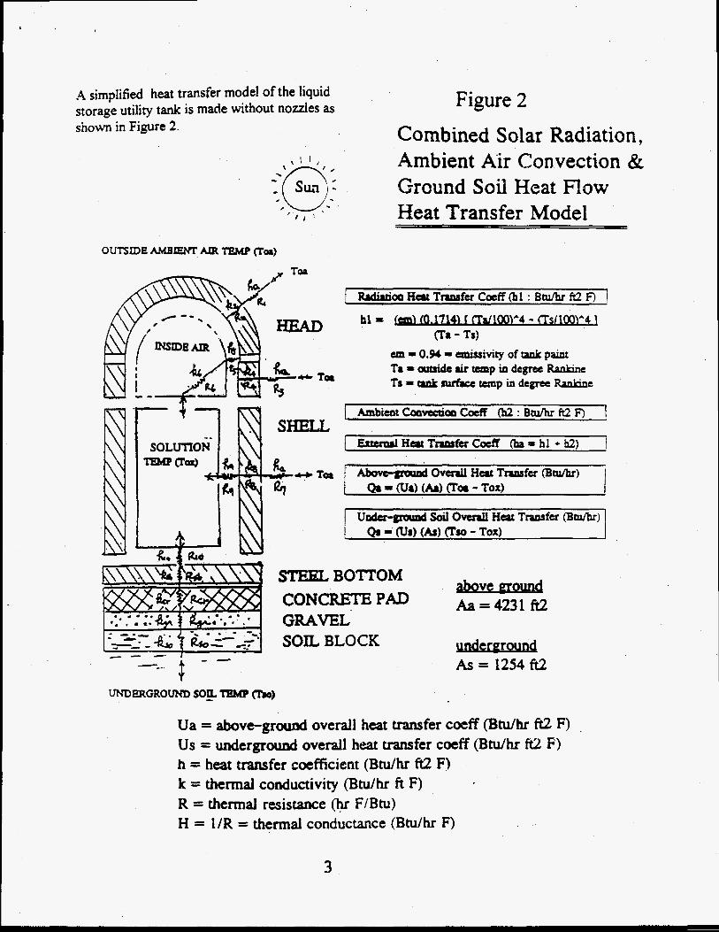
A simplified heat transfer model of the liquid storage utility tank is made without nozzles as shown in Figure 2.
Figure 2 Combined Solar Radiation, Ambient Air Convection & Ground Soil Heat Row Heat Transfer Model
I W o o H a t Tnasfer Coeff Oil : Btumt ft2 F) 1 hl 3: -714) I W W l '4 - ~TS1100~ '4 1
(TI - 'h) un = 0.94 = emissivity of 9nk p u t T8 = artride air temp io degree Ranhne Ts = tank rurfrce temp in degree Rankine
I W o o H a t Tnasfer Coeff Oil : Btumt ft2 F) 1 \ b
C.
-_- - - UNDERGROUKD SO& feMp (Tb)
SHELL
STEEL BOTTOM CONCRETE PAD
SOIL BLOCK GRAVEL'
above mound Aa = 4231 ft2
under erou nd As = 1254 ft2
Ua = aboveground overall heat transfer coeff (Btu/hr ft2 F) I
Us = u n d e r g r d overall heat transfer coeff (Btu/hr W F) h = heat transfer coefficient (BtulhT ft2 F) k = thermal conductivity (Btu/hr ft F) R = thermal resistance (hr F/Btu) H = l /R = thermal conductance (Btulhr F)
3

Nomenclature A = heat transfer area (square foot or ft2) Aam = Aa = 45 + A7 = effecuve area of heat transfer between ambient air and oxalic acid (ft2) Abt = effective area of heat transfer beween ground soil and oxalic acid (ft.2) L = cooductlon hckness (ft) k = thermal coaductwity (Btu / hr ft OF) h = convective coefficient of a u or liquid film (Btu / hr k2 O F ) U = heat transfer coefficient (Bcu / tu ft2 "F) Uam = overall heat traasfer coefficient of ambient air to oxalic acid (Btu / hr ft2 OF) Ubt = overall heat transfer coefficient of underground SOLI to oxalic acid (Btu / hr ft2 OF) R = 1/H = 1 / @*A) = L / &+A) = thermal resistance (hr O F 1 Btu) H = 1IR = thermal conductance (Btu / hr O F ) T = temperature (OF) q or Q = heat flow ( B t u h ) Toa = outside ambient air temperature (OF) E = voltage (volt) Tso = underground soil temperature (OF) dE = voltage difference (volt) Tox = oxalic acid temperature (OF) Re = electncal resistance (ohm) d T c delta T = temperature difference (OF) i = electncal curreot (ampere)
Assumed Thermal Properties (b's. k's). Heat Transfer Areas f A's) and Cooduccoo Tluckness (L's] h l = convectwe film coefficient of wtndy ambient a u on tank head extenor = 4 Btu/hr ft2 OF k2 = thermal cooductlvity of tank head wall = 26.5 Btu / hr 8 O F
b3 = coovccuve film coefficieot of ambient a r on tad shell above liquid level = 4 Bhl / hr ft2 "F k4 = thermal cooductlvity of tank shell wall above liquid level = 26. 5 Btu / hr ft2 OF h5 = coovccuve film coefficient of w e r air on tank mtenor = 1.65 Btu / hr ft2 O F
k6 = thermal cooductwity of tank h e r air = 0.014 Btu / hr ft O F
h7 = convectwe film coefficient of ambieot air on tank shell below liquid level = 4 Btu / hr ft2 "F k8 = thermal cooductwity of tank shell wall below liqud level = 25.5 Btu / hr ft2 O F
h9 = convectwe film coefficient of oxalic acid on tank shell interior = 60 B h / hr ft2 O F
hi0 = coovectlve film coefficient of oxahc acid on rad boaom mterior = 60 Btu / hr ft2 O F
ksb = thermal cooductlvity of rank bottom steel= 26.5 BeunY ft OF kcr = thermal conductlvtty of tank base concrete = 0.44 Btu/hr A OF. kgr = thermal cooductlvity of tank base gravel = 0.4 Bhl/ht A OF. kso = thermal conductlvity of underground sod = 0.5 Btu/hr ft OF. A1 = A2 = heat transfer area of tank h d = 74.36 ft2 L2 = tank head wail cooductlon rhrckness (114 mch) = 0.0208 ft A3 = A4 = shell heat transfer area above liquid level = 0 ft2 @lo046 full, 167.6 ft2 @50% full L4 = tank shell wall cooductam rhrclmess above liquid level (114 mch) = 0.0208 A A5 = tank m e r heat transfer area above liquid level = 74 ft2 @PO% full, 242 ft2 @50% full L6 = equivalent m e r air conduction thickness = 0.86 ft @full, 2.86 ft2 @SO% full A6 = equivalent mer air cooductloa area = 68.7 ft2 @lo096 full, 152.5 ft2 a505 full A7 = A8 = A9 = liquid depth shell heat transfer area = 339 ft2 @lo046 full, 171 ft2 @SO% full L8 = bok shell wall-cooductloo thickness below liqud level (114 tnch) = 0.0208 ft A10 = Asb = Acr = Agr = Am = A k = As = tank boaom heat transfer 8 r ~ = 530.03 ft2 Lsh = steel bottom cooductloo thrckness (1 mch) = 0.0833 R Lcr = ~ssurarxi concrete pad coaductlon duchess = 2 ft Lgr = assumed gravel layer cooductxon hckness = 1 ft Lso = assumed soil depth @ 22" C or 71.6" F = 1 ft
4

The flow of heat (q) through a thermal reistance (R) is ana.agous to the flow o . ..red current (i) through an electncal resistance (Re) because both flows obey SiUUlar formulas as shown below.
'analogy between heat and electncrty th$rmal electrical thermal - elecmcal resistances (R, Re) R Re temperature-voltage differences (dT, dE) dT dE heat flow - direct current (4, i) q = d T l R 1 = dE I Re mulhple resistanccs m senes(Ra,Rb,Re) Ra=Rl+R2 or Rb=R2+R3 Re = Re1 + Re2 multiple resistances m parallel (Rab,Re)
Thermal Resistances The mdrvidual thermal resistances of the oxalic acid tank heat transfer elements are listedbelow.
R1 = 1 I @ I *Al) = thermal resistance between ambient air and tank head extenor R2 = L2 I (k2*A2) = thermal resistance between m e r and outer skins of tank head R3 = I / (h3*A3) = thermal resistance between ambient air and shell extenor above liquid level R4 = L4 / (k4*A4) = thermal resistance between m e r and outer s k m of shell above liquid level R5 = 1 I (hS*AS) = thermal resistance between m e r air and tank mtenor above liquid level R6 = L6 / (k6*A6) = thermal resistance of conduchon inner air R7 = 1 I (h7*A7) = thermal resistance between ambient air and shell extenor below liquid level R8 = L8 I (k8*A8) = thermal resistance between m e r and outer skins of shell below liquid level R9 = 1 I (h9*A9) = thermal resistance between oxalic acid and shell interior below liquid level R10 = 1 / (hlO*A10) = thermal resistance between oxahc acid and tank boaom mtcnor Rsb = Lsb I (ksb*Asb) = thermal resistance between LMer and outer skms of tank bottom Rcr = Lcr I (kcr*Acr) = thermal resistance betwan upper and lower skms of base concrete pad Rgr = Lgr / (kgr*Agr) = thermal resistance between upper and lower skms of tank base gravel Rso = Lso / (kso*Aso) = thermal resistance of underground sod block
By usmg the formula for multiple resistances m scnes or parallel, we can obtam bsd 7
4
(l/Rab)=( l/Ra) + (1Rb) ( 1 /Re)=( 1 /Re 1 )+( 1 /Re2)
the followmg heat transfer equahons (See Fig. 3)
R a = R l + R 2 m senes Rb = R3 + R4 m senes (llRab) = (1/Ra) + (1IRb) m parallel Rc = Rab+ R5 + R6 10 senes Rd = R7 + R 8 + R9 ( l/Ram)=( llRc)+( l/Rd)=Ham=(Uam)*(Aam) - m parallel Rbt=Rso+ Rgr+Rcr+Rsb+R IO= l/Hbt= 1 /(Ubt*Abt) m senes air
Overall ambient air-oxalic acid heat flow Qa = dT / Ram = (Toa - Tox) Uam Aam Overall wound soil-oxalic acid heat flow
m senes film a @ 111
ambient QS = dT Rbt = (TsO - TOX) * Ubt Abt outs,& Acid ~ t l ~ a m m . x - acid
TmkRottomStstl. 3 R+b beifit wLI*
Ambient Air Temperture
TO8
Fig.3 Thermal Resistoocc Diagram of Oxaiic Acid Took byer
sol1
5

CALCULATION RESULTS TANKNO.1 (FREEZING) The fieezing problem analysis of the oxalic acid Tank No. 1 on the cold winter days is based on the following temperature-weather conditions a d basic data of the oxalic acid: items (a) through (m).
The results of the heat transfer calculations are summarized in Table 1.
CONCLUSION The results indicate that:
(1) 17 to 18% of the oxalic acid in the tank will freeze if the solution temperature Is initially 3 1" F and the ambient temperature stays at 10" F for 48 hours.
(2) Less than 1% of the oxalic acid in the tank will fieeze if the solution temperaure is initially 37°F and the ambient temperature stays at 27" F for 48 hours.
(a) ourside ambient temperature : (b) wtrai oxalic acid solution temp. : (c) underground soil temperature : (d) solar radiaaon caff.(negligible): (e) wmdy day air convectloo coefficient : (9 ambient au-tank surface area (AamaAa): (g) ground soil - tank boctom arm (AbeAs): @) tank shell sue : ( I ) oxalic acid mass @hli tank : 0) specific heat of oxalic acid : (k) latent heat of fusion or freezmg : ( I ) tank top bead : (m) tank bottom bead :
Table 1. Summary Of 96 Oxalic Acid Freezing
10" F 31" F 72" F 0 Bru/hrft2'F
(or 27' F) (or 37' F)
4 B t ~ h r f t 2 " F 412 ft2 63 ft2 108' OD x 12 ft long x 0.25' thick 47,547 Ibs (5,700 gallons) 1 BWlb 'F 144 BWlb ASME flanged and dished head (0.25" h c k welded flat head (1' h c k )
1 h t i a l Acid I Solutioo Temwrature : Tox = 31" F I I Air Outside of Tank for 48 how: Tam = 10" F ' Ambient
% Tank Full 100 551 75 %I 50 %I 25% Gallons 5,700 ! 4,275 I 2,850 1 1,425
Outside (Ua) 3.07 1 2.32 I 1.55 I 0.78 ] soil (Us) 0.11 i 0.11 I 0.11 I 0.11 I T (OF) I 30.5 30.5 1 30.5 j 30.5 '
T ( 'C) -0.8 -0.8 -0.8 1 -0.8 1 Esumatcd 96 17.8% 17.7961 17.6% 17.3 R
h z e o I f i o z e n frozen -...A---. -.____ -----J frozen I froze0 .- --...--
0.108
-0.8
Above ground heat flow (Btu/hr) : Qa = Ua x Ao E dTa Underground h u t flow @np/hy) : Qs = Us x As x dTs Uam = Ua = overaU outside-to-solution b u t transfer coeff (Btumt ft2 "F) Ubt = Ws = ovull ground soil-tb-solutron beat traasfer coeff (Btufhr ft2 'F) T = oxalic acid soluuon temperature after 48 hours (OF or 'C)
I
-
6

The upper interface b,etween the oxalic acid and inner sheil surface is the most likely to freeze first and gradually form a hollow cylindrical ice layer with increasing frozen thickness as the cold ambient temperature continues. oxalic acid solution tank.
The thermal behavior of the frozen oxalic acid layer is more like a solid conduction rather than a liquid convection.
Figure 4 is a sketch of the partially frozen
OUTSIDE AMBIENT AIR TEMPERATURE (Toa)
“OM
CONCRETE PAD
UNDERGROUND SOIL TEMPERATURE (TSO),
Figure 4 Partially Frozen Oxalic Acid Tank -
7

CALCULATION RESU LTS TANK N0.2 (SOLAR HEAT) The solar radiation heat problem aidysis of STPB Tank No.2 on the hot summer days is based on the failowing temperature-weather ccnditions a d bssic data of theSTPR: iterris (a) through (e).
The results of the heat transfer calculations are summarized in Table 2.
REFERENCES (1) J. Homan, " Heat Transfer ", 1963,
McGraw Hill.
(2) E. Obert, " Principies of Heat Transfer ", 1965, International Textbooks
(3) R. Peny, " Perry's Chemical Engineers' Handbook '' , Sixth Edition, McGraw Hill
~
(a) outside ambient temperature (b) STPB SO1UtlO~ temp 8t 6 8.m. (c) underground soil temp (d) average solar ndrahon caff (e) ambient air convceuioa caff.
107" F 80" F 72" F 1.12 B t u 5 ft2 F 1.65 B t u 5 ft2 F
Ua = overall ouside-to-solutloa k t transfer coeff ( B t u 5 ft2 F) Us = ovuli ground soil-to-solutxm heat transfer caff (Bru/hr ft2 F) T I average solution temperature after 8 hours or 2 p.m.("F or "C)
Aa = 4231 h2 = rmbient air-unk surface area As = 1254 ft2 = ground soil-unk bottom area
above ground heat flow ( B W ) : Qa = Ua x A8 x dTa underground h u t flow ( B t u 5 ) : Qs = Us x As x dTs
Table 2. Summery of STPB Tank Heat Transfer Anrlysis
I Gallons I 188.000 1 141.000 I 94,000 1 47,000 1 I Ouulde (ut) i 1.57 1 1.18 1 0.79 1 0.39 1 I Soil (US) i 0.11 I 0.11 I 0.11 I 0.11 I I T (OF) 1 81.35 I 81.18 I 80.98 i 80.36 I I T ("0 1 27.4 1 27.3 1 27.2 I 27.0 i degradauon none none 1 - DoSSlbllllW I :E i srfe I safe 1 I CONCLUSION Based on the above calculation results, STPB solution cf Tank No.2 will not be degraded due to summer-time solar radiation heat
8

BIOGRAPHY
Ki C. Kwon is a Fellow Engineer of Westinghouse Savannah River Company, Aiken, SC Tel : 803-557-8720.
As a PhD in Mechanical Engineering from North Carolina State University at Raleigh, NC he has received 13 years of full time multi-university education in engineering (MechanicaX, Chemical, Civil-Structural, MetallurgicaX, Mathematics-Computer and Textiles). He is a twenty- six-year member of American Society of Mechanical Engineers, a member of American Nuclear Society, and a Registered Professoinal Engineer of North and South Carolina.
He has over 25 years of industrial experience in machine & process equipment design such as rotating equipment, heat exchangers, ASME code pressure vessels, compressors, WAC, waste management, and nuclear-fire-safety components and engineering analysis in thermal, fluid, vibration, fatigue stress, component failure, seismic design, and scientifk-engineering computer programming.
H e has worked as a designer and consultant for the nuclear & power industry (government and commercial), textile, paper, and machine-equipment manufacturers.