engineering manual thermodrive technology
TRANSCRIPT

ENGINEERING MANUAL
THERMODRIVE TECHNOLOGY

© Intralox, L.L.C. No part of this publication may be reproduced, transmitted, transcribed, stored in any retrieval system, ortranslated into any human or computer language by any means or in any form without prior written permission of Intralox.
Intralox may make changes without notice to both this document and to products described by this document. Nothing in thisdocument is intended to give rise to any obligation, contractual or otherwise, on the part of Intralox.
The original version of this document is written in English. Any version in a language other than English is a translation of theoriginal document. Do not modify the equipment, components, or equipment assemblies. Do not remove or modify any factory-installed safety features without the written consent of Intralox. Intralox is not responsible for failures due to incorrect usage of theequipment.
Intralox, L.L.C. does not warrant that the design and/or operational function of any machine that incorporates and/or intends toincorporate Intralox, L.L.C. products, conforms to any local, state, or national regulations and standards relating to public safety,worker safety, safety guards, sanitation safety, fire safety, or any other safety regulations. ALL PURCHASERS AND USERS SHOULDCONSULT THEIR APPROPRIATE LOCAL, STATE, AND NATIONAL SAFETY REGULATIONS AND STANDARDS.
Certain Intralox products are made of plastic and can burn. If exposed to an open flame or to temperatures above Intraloxspecifications, these products may decompose and emit toxic fumes. Do not expose Intralox conveyor belting to extremetemperatures or open flame. Flame retardant belt products are available in some series.
Prior to installing, aligning, cleaning, lubricating, or performing maintenance on any conveyor belt, sprocket or system, consult thefederal, state and local regulations in your area regarding the control of hazardous/stored energy (lockout/tagout).
Statement of Use: This document is included under the fair use exemption and is restricted from further use.
2Engineering Manual-ThermoDrive Technology

TABLE OF CONTENTS1 USING THIS MANUAL....................................................................................................................................5
ACCESS AND NAVIGATION............................................................................................................................ 5UPDATES......................................................................................................................................................... 5
2 INTRODUCTION............................................................................................................................................. 6ABOUT INTRALOX...........................................................................................................................................6INTRALOX HYGIENIC SYSTEM.......................................................................................................................6CUSTOMER RESOURCES.............................................................................................................................. 6THERMODRIVE TENSIONLESS BELT SYSTEM..............................................................................................8
3 CONVEYOR DESIGN...................................................................................................................................... 9DESIGN CONSIDERATIONS............................................................................................................................9THERMODRIVE DESIGN PRINCIPLES............................................................................................................9THERMODRIVE HYGIENIC RECOMMENDATIONS...................................................................................... 11
4 CONVEYOR FRAME DESIGN...................................................................................................................... 13DIMENSIONS................................................................................................................................................. 13FRAMEWORK................................................................................................................................................ 13
5 DRIVE END DESIGN.....................................................................................................................................16DRIVE SHAFT.................................................................................................................................................16DRIVE SPROCKETS.......................................................................................................................................16DRIVE PULLEYS............................................................................................................................................ 17POSITION LIMITERS......................................................................................................................................18POSITION LIMITER LOCATION BY DRIVE TYPE.......................................................................................... 20BELT SCRAPER............................................................................................................................................. 21SCRAPER ACTING AS A LIMITER CONSIDERATIONS................................................................................ 22INTRALOX DRIVE UNIT..................................................................................................................................23
6 IDLE END DESIGN........................................................................................................................................24IDLE SHAFT................................................................................................................................................... 24SPROCKETS, WHEELS, AND ROLLERS.......................................................................................................24
7 CARRYWAY DESIGN....................................................................................................................................26SUPPORT RAIL GENERAL GUIDELINES...................................................................................................... 26STRAIGHT, PARALLEL ARRANGEMENT...................................................................................................... 26ANGLED CHEVRON ARRANGEMENT...........................................................................................................28CARRYWAY WITH FLIGHTS, SIDEWALL, OR FLIGHT NOTCHES............................................................... 28
8 RETURNWAY DESIGN................................................................................................................................. 30BELT DIMENSIONS....................................................................................................................................... 30CATENARY SAG............................................................................................................................................ 30MANAGING BELT ACCUMULATION.............................................................................................................30RETURNWAY SUPPORT GUIDELINES......................................................................................................... 32RETURNWAY WITH FLIGHTS OR SIDEWALLS............................................................................................ 33
9 BELT CONTAINMENT.................................................................................................................................. 35HYGIENIC RECOMMENDATIONS................................................................................................................. 37
10 TROUGHED CONVEYORS.........................................................................................................................38CONTINUOUS CARRYWAY FOR BELTS WITH NO TROUGH GROOVE......................................................38V-SHAPED CARRYWAY FOR BELTS WITH ONE TROUGH GROOVE......................................................... 39U-SHAPED CARRYWAY FOR BELTS WITH TWO TROUGH GROOVES...................................................... 39
11 DIMENSION CHANGES..............................................................................................................................40OVERVIEW..................................................................................................................................................... 40TOTAL BELT DIMENSION CALCULATION....................................................................................................40
3Engineering Manual-ThermoDrive Technology
12 BELT SELECTION.......................................................................................................................................43VISUAL OVERVIEW........................................................................................................................................43BELT SELECTION CONSIDERATIONS..........................................................................................................44BELTS, FEATURES, AND ACCESSORIES AVAILABILITY REFERENCE.......................................................46
13 BELT FABRICATION.................................................................................................................................. 65BELT JOINING OPTIONS...............................................................................................................................65BELT JOINING CONSIDERATIONS............................................................................................................... 65BELT FEATURES........................................................................................................................................... 67BELT ACCESSORIES.....................................................................................................................................68
14 DRIVE AND IDLE END COMPONENTS.....................................................................................................74DRIVE END SELECTION CONSIDERATIONS................................................................................................74INTRALOX DRIVE UNIT FOR S8050.............................................................................................................. 74SHAFTS..........................................................................................................................................................75RETAINING COMPONENTS.......................................................................................................................... 76SPROCKETS.................................................................................................................................................. 79POSITION LIMITERS......................................................................................................................................84SCRAPERS.................................................................................................................................................... 87SUPPORT WHEELS AND ROLLERS............................................................................................................. 88
15 CARRYWAY AND RETURNWAY COMPONENTS.................................................................................... 91SUPPORT RAILS/WEARSTRIPS....................................................................................................................91SHAFTS..........................................................................................................................................................92RETURN ROLLERS........................................................................................................................................92TROUGH CONVERTER..................................................................................................................................92
16 SPLICING EQUIPMENT..............................................................................................................................94THERMODRIVE SPLICING SYSTEM V2........................................................................................................94THERMODRIVE STREAMLINE SPLICING SET..............................................................................................95STREAMLINE SPLICER DECK INSERTS.......................................................................................................96SPLICING EQUIPMENT SPARE COMPONENTS.......................................................................................... 96S8140 STREAMLINE SPLICING SET ACCESSORY PACK........................................................................... 97THERMODRIVE STREAMLINE HAND-HELD BELT PREPARATION TOOL...................................................97THERMODRIVE BELT END ROUTER SET.....................................................................................................98BELT END ROUTER.......................................................................................................................................99
17 BELT MATERIAL PROPERTIES...............................................................................................................100MATERIAL COMPLIANCE............................................................................................................................100TEMPERATURE FACTORS..........................................................................................................................100BELT CHEMICAL RESISTANCE GUIDE...................................................................................................... 102
TABLE OF CONTENTS
4Engineering Manual-ThermoDrive Technology

1 USING THIS MANUALThe ThermoDrive® Technology Engineering Manual contains information about Intralox ThermoDrivetechnology. For information about Intralox modular plastic products, visit www.intralox.com for the currentIntralox Modular Plastic Conveyor Belts Engineering Manual.
The recommendations provided in the design guidelines have proven successful for most installations.Failure to follow the guidelines presented in this manual results in improper performance of ThermoDrivebelting.
For extreme or unique conveyor designs or detailed assistance when considering ThermoDrive solutions,contact Intralox for assistance. See contact information on the back cover.
ACCESS AND NAVIGATIONPrinted manuals are available from Intralox Customer Service.
• When printed manuals are black and white, see color images in the electronic manual.
• Electronic manuals are available for download at www.intralox.com.
UPDATES• The ThermoDrive Technology Engineering Manual is fully updated each July.
• New products released after the update are not added to the manual until the next July.
• New product information is available from Intralox Customer Service until the manual is updated.
5Engineering Manual-ThermoDrive Technology

2 INTRODUCTIONABOUT INTRALOXWith more than 40 years of experience, Intralox continues to lead the way in helping customers achieve theirgoals by offering comprehensive conveyance solutions that create significant economic value. Intraloxdelivers innovative, premium technology within a direct business model and a global, industry-specificstructure.
Our industry-specific teams have an in-depth knowledge of customer applications, provide technical supportand consulting, and offer 24/7 customer service. Working with Intralox allows you to experience ouruncompromising commitment to providing solutions and solving customer challenges.
As the pioneer of hygienic conveyance, Intralox delivers results that matter to our customers. We providereliable operational performance, dramatic reductions in cost, a competitive edge in challenging markets,and the highest standard in food safety risk management. We continue to go beyond industry standards withnew products, equipment, solutions, and services. Our commitment to innovation has led to over 1400active patents around the world. When our customers have challenges, we invent smart solutions to meetthem.
INTRALOX HYGIENIC SYSTEMContact Intralox to find out how our complete hygienic system can meet your toughest hygienic challengesusing:
• Hygienic belts and components, like our ThermoDrive products, that optimize belt performance usingpatented, tensionless technology
• Research and development through ongoing testing by trained industry experts and global collaborationwith customers
• Consulting, education, and training to enhance customer sanitation, quality, engineering, and operationsleadership in food safety applications
• Customer support from award-winning, technical experts
CUSTOMER RESOURCESFor unique conveyor designs or general assistance when considering ThermoDrive solutions, contactIntralox. See contact information on the back cover.
6Engineering Manual-ThermoDrive Technology

ENGINEERING ASSISTANCE AND DESIGN REVIEW: Intralox can provide engineering assistance, designreviews, and computer analytics for specific applications. Intralox also provides specific belt and drivecalculations as well as component requirements and suggestions.
CAD DRAWING FILES: AutoCAD.DXF files for ThermoDrive sprockets and limiters are available. The filescontain product details for use in CAD conveyor designs. Visit www.intralox.com for files.
HYGIENIC CONSULTING AND EDUCATION: Commercial Food Sanitation L.L.C., an Intralox company,integrates strategic consulting, expertise, and training programs to provide durable solutions to food safetyand sanitation challenges for food processing plants across the globe. For more information, visitwww.commercialfoodsanitation.com.
PRODUCT LITERATURE: For ThermoDrive user manuals and additional product documents, visitwww.intralox.com. Navigate to Resources > Brochures and Technical Guides.
COMPANY, PRODUCT, AND APPLICATION INFORMATION: For information on Intralox, product features,and product applications, visit www.intralox.com.
2 INTRODUCTION
7Engineering Manual-ThermoDrive Technology

THERMODRIVE TENSIONLESS BELT SYSTEMIntralox ThermoDrive technology combines homogeneous thermoplastic material and the positive drivefeature of modular plastic belting with a unique, patented drive engagement solution. This combinationcreates a one-of-a-kind tensionless belt system that provides exceptional customer value.
• Eliminates the cost and complex adjustments associated with managing a tensioned, positive drive or flatbelt system.
• Provides reliable, predictable drive performance and reduces costs.
• Extends belt life, minimizes component wear, and improves product yield.
ThermoDrive technology provides new opportunities in hygienic conveyance design.
• The lightweight, loose conveyor fit makes belts easy to lift and to clean.
• The open access component and conveyor design possibilities allow for cleaning in place withoutconveyor adjustment.
• The homogeneous belt makes it easy to wipe down for quick product changes and offers fast dryingcapabilities.
2 INTRODUCTION
8Engineering Manual-ThermoDrive Technology
3 CONVEYOR DESIGNDESIGN CONSIDERATIONSThe Intralox ThermoDrive tensionless belt system offers various belt styles, materials, and colors. Once abelt is selected, the customer chooses from many fabrication choices such as perforations, grooves, flights,and sidewall.
To make the appropriate selections when designing for a particular application, consider operating andenvironmental conditions such as:
• Conveyance requirements (horizontal, elevating, inclining)
• Overall dimensions of the installed belt
• Speed of belt travel
• Conveyed product (weight, shape, size, temperature, moisture content, texture, frictional nature)
• Processes (cooling, washing, rinsing, draining, drying, cleaning)
• Hygienic requirements
• Operating environment (temperature, humidity, chemical nature, abrasive nature)
• Drive system type (end, center)
• Facility or space limitations
Information contained in this manual covers the basic conveyor design guidelines for the ThermoDrivetensionless belt system sold by Intralox. These general recommendations work for most applications.Contact Intralox for industry-specific suggestions to ensure success for your application.
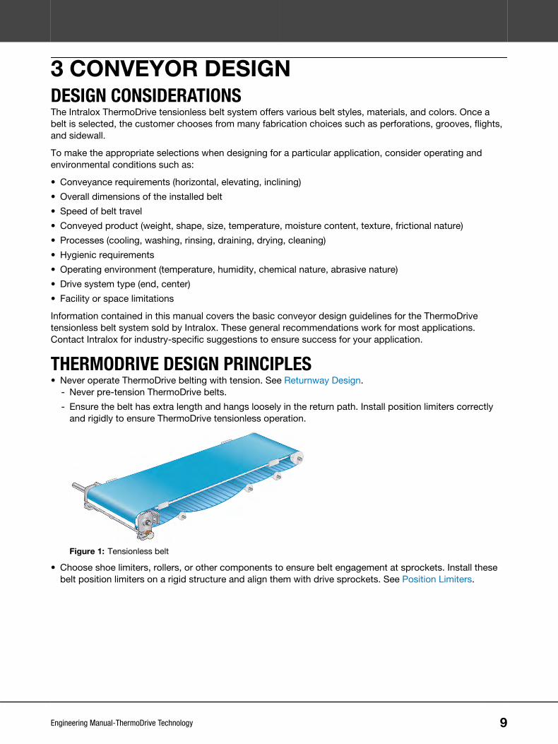
THERMODRIVE DESIGN PRINCIPLES• Never operate ThermoDrive belting with tension. See Returnway Design.
- Never pre-tension ThermoDrive belts.
- Ensure the belt has extra length and hangs loosely in the return path. Install position limiters correctlyand rigidly to ensure ThermoDrive tensionless operation.
Figure 1: Tensionless belt
• Choose shoe limiters, rollers, or other components to ensure belt engagement at sprockets. Install thesebelt position limiters on a rigid structure and align them with drive sprockets. See Position Limiters.
9Engineering Manual-ThermoDrive Technology

• Prevent the belt from bending tighter than the stated minimum belt backbend diameter. Ensure alltransitions, rollers, wheels, and sprockets are at or above the minimum bend radius.
Figure 2: Components at or above the minimum bend radius
• Lock sprockets, rollers, or support wheels in place on shafts at the drive and idle ends.
Figure 3: Shafts with locked components
NOTE: Retrofit projects can prohibit using all the ThermoDrive design features required for optimalperformance. Contact Intralox Customer Service for application-specific suggestions.
Figure 4: Conveyor belt components
A Position limiterB Drive sprocketC Belt accumulationD Containment blockE ThermoDrive beltF Drive barsG Carryway supportH Returnway supportI Support wheel
NOTE: The actual number and type of position limiters (A) can vary from the illustration. The desired locationof containment block (D) can vary from the illustration.
See www.intralox.com for ThermoDrive Installation and Maintenance manuals.
3 CONVEYOR DESIGN
10Engineering Manual-ThermoDrive Technology

THERMODRIVE HYGIENIC RECOMMENDATIONSImplementing ThermoDrive design principles and other design considerations in this document allowsoptimal ThermoDrive operational performance. Using the hygienic recommendations provided also improvessanitation and minimizes hygienic risks in food conveyance equipment.
HYGIENIC DESIGN PRINCIPLESUnderstand and follow reputable hygienic design principles, standards, and guidelines, as well as regulatoryrequirements, when designing ThermoDrive conveyor systems for food industry applications. CommercialFood Sanitation promotes these design principles, standards, and guidelines during hygienic design classesand through direct support of food industry-based clients:
• Design equipment using compatible and non-toxic materials. Materials must withstand the intendedsanitation and production processes, the food product produced, and the processing environment.
• Design equipment for sanitary operational performance.- Design and construct equipment to facilitate maintenance and sanitation.
- Keep structures as simple as possible to provide open access to all areas during sanitation.
Figure 5: Simple structure to provide open access for sanitation
- Minimize tools required for inspection, maintenance, and sanitation protocols.
- Avoid fasteners when possible, or at least in product contact areas and above the exposed productcontact surfaces.
- Prevent cross-contamination during disassembly by designing component storage into the conveyorframe.
- Ensure related equipment systems are hygienically compatible with conveyors.
- Ensure adequate conveyor clearance from environmental surfaces and other processing equipment.
- Avoid plated, painted, and coated surfaces when possible.
- Consider the hygienic design of all enclosures and utilities.
3 CONVEYOR DESIGN
11Engineering Manual-ThermoDrive Technology

• Design and construct equipment to prevent the ingress, survival, and multiplication of microorganisms.- Prevent liquid collection by designing components to self-drain.
Figure 6: Correct joint assembly
- Eliminate non-hermetically sealed, hollow fabrication at or above the exposed product contact areas atminimum.
- Eliminate niches, butt joints, lap joints, and the use of fasteners when possible.
- Ensure joints and welds are flush, smooth, and free of pits, cracks, and corrosion.
- Ensure internal corners of less than 135° have a minimum 0.125 in (3 mm) radius.
- Avoid designs with sleeved assemblies, press fit, or shrink-fit designs when possible.
NOTE: More hygienic recommendations are provided throughout the manual.
GENERAL CLEAN-IN-PLACE RECOMMENDATIONSGeneral, safe Clean-in-Place (CIP) recommendations:
• Single row of fan nozzles on each manifold
• 50-degree fan nozzle
• 5 in (13 cm) or more from nozzle tip to belt
• Spray pattern is at 90-degrees to the belt
• Water pressure is between 150 PSI (10 bar) and 250 PSI (17 bar)
• Minimum water volume = Volume per Minute per Nozzle x Number of Nozzles
• Water temperature is between 120°F to 130°F (49°C to 54°C)
• Higher belt speeds are more efficient
NOTE: For CIP specifications outside of these recommendations, please contact the Intralox TechnicalServices Group (TSG).
HYGIENIC STANDARDS RESOURCESRefer to the most current sanitary standards and information when using ThermoDrive design guidelines tomeet strict hygienic standards. Consider information from organizations such as:
• American Meat Institute (AMI)
• Grocery Manufacturers Association (GMA)
• 3-A Sanitary Standards, Inc.
• European Hygienic Engineering and Design Group (EHEDG)
• NSF International Food Safety and Health Sciences Divisions
NOTE: Consider consulting the following standards: EN 1672-2 (European Committee for Standardization),NSF 14179, EC 852 (European Council of 29 April 2004), and EC 853 (European Council of 29 April 2004).
3 CONVEYOR DESIGN
12Engineering Manual-ThermoDrive Technology

4 CONVEYOR FRAME DESIGNDIMENSIONSCertain dimensions are required on all conveyors using ThermoDrive belting. Design the conveyor framedimensions based on the chosen ThermoDrive belt series and sprocket size.
A
C
B
A Distance between the sprocket shaft centerline and the top of the carrywayB Distance between the sprocket shaft centerline and the beginning of the carrywayC Distance between the top of the carryway and the top of the returnwayFigure 7: Conveyor frame dimensions
S8026Conveyor Frame Dimension Guidelines
S8026 Sprocket Description A B CPitch Diameter Outer Diameter No. of Teeth
in mm in mm in mm in mm in mm2.0 51 1.9 48 6 0.75 19 1.70 43 1.87 48
2.5 64 2.5 64 8 1.06 27 2.01 52 2.50 64
3.2 81 3.2 81 10 1.39 35 2.34 60 3.16 81
3.9 99 3.8 97 12 1.71 43 2.66 68 3.80 97
6.4 163 6.4 162 20 2.99 76 3.40 87 6.36 162
S8050Conveyor Frame Dimension Guidelines
S8050 Sprocket Description A B CPitch Diameter Outer Diameter No. of Teethin mm in mm in mm in mm in mm4.0 102 3.7 94 6 1.68 42 2.53 65 3.71 95
5.2 132 5.0 127 8 2.32 58 2.97 76 4.97 127
6.5 165 6.3 160 10 2.95 75 3.35 86 6.24 159
7.7 196 7.6 193 12 3.61 91 3.71 95 7.55 192
10.3 262 10.1 255 16 4.84 123 4.32 110 10.03 255
FRAMEWORKThermoDrive tensionless belt systems require a conveyor framework appropriate for a loosely fitted belt. Thedesign must include open spaces and minimal joints for appropriate sanitation and maintenance based onthe application.
13Engineering Manual-ThermoDrive Technology

• Ensure the frame design allows for belt lifting and cleaning at the conveyor or endless belt removal foreasy conveyor cleaning.
• Ensure the conveyor frame allows for belt installation and future repairs. For example, there must beenough area above the carryway for belt splicing or provide a cantilevered or break-away support designin the conveyor for endless belt installation.
Framework Component DataComponents Recommended Material Surface Finish
Conveyor framework in the product contact area 316 or 304 stainless steel Not to exceed Ra32 micro-inches(Ra0.8 µm)
Conveyor framework structural members and guards outside theproduct contact area
304 stainless steel Not to exceed Ra125 micro-inches(Ra3.2 µm)
HYGIENIC RECOMMENDATIONSReview Hygienic Design Principles before following these recommendations. See HygienicDesign Principles.General Framework
• Keep frame construction as simple as possible.
• Use chemically resistant materials.
• Use solid round or angled profiles when possible. Use square profiles only when placedat an angle so water drains fully.
• Eliminate hollow tube and non-hermetically sealed joints when possible—at or abovethe exposed product contact areas.
- Fully seal hollow fabrication with continuous purge welds to prevent interiorcontamination.
- Avoid tapping or drilling hollow frame components.
- Use standoffs when hermetically sealed joints are not possible.
• Eliminate exposed threads, niches, butt joints, and lap joints.
• Fully weld connections with a minimum 0.125 in (3 mm) radius.
• Grind flush all product contact surface welds.
• Polish all external surfaces to the needed Ra surface finish using hand polishingtechniques, bead blasting, or electro-polishing. Passivate (pickle) the surface whenrequired to meet requirements.
NOTE: Do not passivate with any ThermoDrive or other Intralox belt present in theroom. Nitric acid passivation destroys ThermoDrive and other Intralox polymer belts.
• Install simple belt lifting and idle shaft removal mechanisms. Ensure easy access to allframe components under the belt and inside the frame for cleaning, sanitation, andinspection.
• Periodically inspect the conveyor frame for wear marks, pitting, and cracking.
Frame Supports BA
4 CONVEYOR FRAME DESIGN
14Engineering Manual-ThermoDrive Technology

HYGIENIC RECOMMENDATIONS• Minimize support leg quantity and raise conveyor cross members where possible.
- Locate cross members under the returnway belt supports so that a loosely fitted beltdoes not sag into the cross members.
- Design a minimum 18 in (457 mm) clearance between the floor and a direct productcontact surface (A). For example, the product contact side of belt while returningunder the conveyor and all guide rollers that contact that side of the belt.
- Design a minimum 12 in (305 mm) clearance between the floor and the bottom oflower conveyor framework (B).
• Design leg connections without niches, butt joints, or lap joints and use high-qualitywelds.
• Design portable conveyors with standoffs fully welded between legs just above castersand top plates. Slope the top plate 0.125–0.250 in (3.2–6.4 mm) for drainage.
• Design threaded leg adjustments in one of two ways:
- Use only internal threaded leg adjustments that can be fully hermetically sealed, butdo not penetrate the primary hollow tube support.
- Use external leg adjustments with full external and cleanable surfaces.
• Consider the following designs for installing conveyor feet or pads to the floor.
- Design equipment leg and foot mounts on elevated masonry piers with sealant underfeet.
- If bolting feet directly to the floor, choose flat foot pads without concave voids. Useminimal fasteners, a compatible sealant, and frequent deep cleaning.
- Design solid stainless steel legs without feet for installation within a solid masonryfloor with properly rated masonry grout.
NOTE: Legs without feet are not appropriate with floor coatings on masonry or insome tile applications.
4 CONVEYOR FRAME DESIGN
15Engineering Manual-ThermoDrive Technology

5 DRIVE END DESIGNThermoDrive belting supports several drive designs:
• By shafts, sprockets, and position limiters
• By motorized pulleys with Intralox-approved drive geometry and position limiters
• By the patented Intralox Drive Unit
Depending on the process and product, certain drive methods provide a more hygienic solution.
DRIVE SHAFTSquare shafts provide maximum belt drive efficiency. Square shafts allow the positive transmission of torqueto the sprockets without keys and keyways.
• Choose square shafts made of 303, 304, 316, or 17-4 PH stainless steel.
• Fasten shafts to the conveyor frame level and square with the belt path. Further adjustment is notrequired.
• Choose the standard 1.5 in or 40-mm shaft to ensure enough rigidity to minimize deflection in mostapplications.
• Lock each drive sprocket in place on the shaft.
• When using stainless steel circular retainer rings, consider sprocket hub width when defining retainer ringgroove locations on square shafts.
• Use heavy-duty split retainer rings as needed.
• For retainer rings, sprocket spacers, and customized Intralox square shaft options, see Drive and Idle EndComponents.
D
C
B
A
E
F
Figure 8: Square drive shaft components
A ShaftB Bearing journalC Square section (distance between bearings)D Drive end journalE Retainer ring grooveF Keyway for driver hub (not required on idle shaft)
DRIVE SPROCKETSChoose Intralox ThermoDrive sprockets based on ThermoDrive belt series and hygienic requirements.Design the drive system based on the following installation requirements:
16Engineering Manual-ThermoDrive Technology

• Install outside sprockets so the sprocket tooth outside edge is 0.5–1.5 in (13–38 mm) from the belt edge.Keep this distance as narrow as possible.- For flighted belts, the sprocket tooth outside edge is often 0.5 in (13 mm) from the belt edge. Order a
large flight indent to meet the required clearances and sprocket-to-limiter alignment.
- For ThermoLace™ belts, the sprocket tooth outside edge must be a minimum of 1 in (25 mm) from thebelt edge. This prevents the sprocket from catching the ThermoLace edges.
Figure 9: Outside sprockets installation
• Position sprockets as symmetrically as possible with a maximum 3 in (76 mm) centerline spacing.
• Add sprockets to prevent the belt from bowing more than 0.08 in (2 mm) between sprockets duringoperation.
• Limit sprocket lateral movement to +/-0.125 in (3 mm) using retaining rings or sprocket spacers.
A Retaining ringsB Sprocket spacersFigure 10: Retaining rings and sprocket spacers
• Consider using stacked sprockets in heavily loaded applications or when precise scraping is critical.
Figure 11: Stacked sprockets
HYGIENIC RECOMMENDATION• Use ThermoDrive EZ Clean™ sprockets designed for self-draining and spray-through sanitation. This style is well suited for CIP
systems.
• Use Intralox sprocket spacers for a more hygienic solution.
• Ensure clean-in-place systems are designed so that spray fully covers the sprockets.
DRIVE PULLEYSIf choosing a motorized pulley, use the following guidelines. Contact Intralox Customer Service for pulleyevaluation suggestions.
• Choose a rigid, full-width drive unit with non-pliable teeth that meets ThermoDrive specifications.
• Ensure the pulley surface has acceptable wear resistance characteristics and has a coefficient of friction(COF) of 0.35 or less against belting.
5 DRIVE END DESIGN
17Engineering Manual-ThermoDrive Technology

For example, the pulley surface can be made of acetal, ultra-high molecular weight polyethylene (UHMW-PE)resin, 304 or 316 stainless steel, or covered in a hard polyurethane shell. A polyurethane shell of inadequatehardness wears quickly and shortens the life of the motorized pulley. Options depend on the application.
HYGIENIC RECOMMENDATIONS• Use full width, continuous drive geometry to minimize joints and crevices.
• Ensure pulley surface materials are approved for product contact by regulatory agencies.
• Ensure the drive assembly has minimal exposed fasteners and uses a food-grade lubricant.
• Set shaft ends in slots for tool-free conveyor disassembly or unit removal when cleaning.
5005716-CVY-??POSITION LIMITERSPatented ThermoDrive tensionless operation requires the use of position limiters in the form of curved shoes,circular rollers, scrapers, or other innovative designs. Position limiters ensure proper, continuousengagement between ThermoDrive belts and drive sprockets without using tension.
For Intralox shoe-style position limiters and available rollers, see Drive and Idle End Components.
Contact Intralox Customer Service for application-specific suggestions.
POSITION LIMITER GUIDELINES• For ideal end drive design, use concave, shoe-style position limiters that span a minimum of three S8026
drive bars, two S8050 drive bars, or three S8140 drive lugs.
• Use rollers or scrapers as limiters in certain applications.- Use rollers as limiters for abrasive end drive applications.
- Mount roller limiters on a shaft supported by ball bearings.
- Use roller limiters for center drive applications. See Position Limiter Location by Drive Type.
- Use scrapers as limiters only in lightly loaded applications. See Scraper Acting as a LimiterConsiderations.
• Ensure limiter belt contact surface material is UHMW-PE with a molecular weight of 3,500,000 Da (amu) orhigher, non-lubricated, natural (uncolored, no additives), and 63 Ra maximum surface roughness. Neveruse a limiter with an acetal contact surface.
POSITION LIMITER ALIGNMENT AND SPACING• Ensure limiter mounting structures are rigid enough to handle 40% of the belt load. For example, prevent
the mounting beam or crossbar from deflecting more than 0.05 in (1.25 mm) under a uniformly distributedload of 40% of the calculated belt pull.
• Align limiters with drive sprockets so they can support the seated belt.
• Place shoe-style limiters with a 0.005–0.05 in (0.13–1.25 mm) spacing between the seated belt and thelimiter. Limiters too far from the belt cause belt engagement issues.
5 DRIVE END DESIGN
18Engineering Manual-ThermoDrive Technology

• Ensure limiters do not exert pressure through the belt and onto the sprockets. Limiters pinching the beltagainst the drive sprocket can cause intermittent drive disruption or noisy drive operation.
A 0.005–0.05 in (0.13–1.25 mm) spacingFigure 12: Correct limiter placement
• Set roller limiters with a maximum 0.02 in (0.5 mm) spacing between the seated belt and the roller.
• Keep a raised tooth beneath the belt when setting the roller limiter. If a drive pocket between raised teethis at the roller during installation, the roller can be installed too close to the sprocket. Poor installation cancause belt pinching at startup and belt damage.
A 0.02 in (0.5 mm) spacingFigure 13: Correct placement of sprocket tooth beneath belt when setting the roller limiter
• Plan to make periodic inspections for limiter wear and secure mounting. Replace position limiters or adjustposition limiter locations periodically to maintain proper spacing.
BELTS WITHOUT ACCESSORIES• Place the limiter support structure laterally across the belt width and parallel to the drive shaft.
• For spaced or stacked sprockets, align limiters with sprockets with a maximum 3 in (76 mm) centerlinespacing.
Figure 14: Correct alignment and clearance for belts without accessories
5 DRIVE END DESIGN
19Engineering Manual-ThermoDrive Technology

BELTS WITH ACCESSORIES• Align a limiter with each outermost drive sprocket.
• Ensure a 0.25 in (6 mm) clearance between flight or sidewall edges and position limiter edges (A).
• Ensure a 1.25 in (32 mm) minimum flight or sidewall indent (B) to allow for the installation of positionlimiters.
• Ensure a 0.125 in (3 mm) clearance between the belt edge and containment components (C).
A 0.25 in (6 mm) clearanceB 1.25 in (32 mm) clearanceC 0.125 in (3 mm) clearanceFigure 15: Correct alignment and clearance for belts with accessories
POSITION LIMITER LOCATION BY DRIVE TYPEEND DRIVEIdeal end drive design allows the belt to pull at the full load rating with a belt wrap of 165-180°.
A 165–180° from the top of the sprocketB 165–180° from the top of the sprocket on inclineFigure 16: Position limiter placement
CENTER DRIVEFor center drive designs, use the following recommendations for sprocket and position limiter types andlocations.
• Use a center drive sprocket with a minimum of 10 teeth.
5 DRIVE END DESIGN
20Engineering Manual-ThermoDrive Technology

•- For a belt with flights, contact Intralox Customer Service for application-specific suggestions.
Figure 17: Center drive sprocket and position limiter locations
• Use roller limiters to achieve a 90° belt wrap. This also provides a compact drive system.- Ensure roller limiter diameters meet or exceed the belt minimum backbend diameter.
- For a bi-directional drive, place roller limiters at the 135° and 225° positions from top center.
- For a uni-directional drive with the drive near the discharge end, place one roller limiter where the beltshould first contact the sprockets. Then, place a second roller limiter 90° from the first.
A Bi-directional drive roller limiter positionsB Uni-directional drive roller limiter positionsFigure 18: Bi-directional and uni-directional drive roller limiter positions
HYGIENIC RECOMMENDATIONS• Design position limiter mounting without niches, butt joints, lap joints, and fasteners when possible.
• Ensure component materials are approved for product contact by regulatory agencies.
• Consider using the Intralox Drive Unit for optimal hygienic and operational performance for end drive applications.
BELT SCRAPERInclude a scraper with ThermoDrive belt conveyor applications to remove product residue automaticallyduring operation. Plan to use position limiters with any scraper. See Scraper Acting as a LimiterConsiderations.
NOTE: Worn or deflecting scrapers reduce operational performance. This can reduce product yield, limitereffectiveness, and scraping efficiency.
SCRAPER DESIGN CONSIDERATIONS• To optimize scraper performance, consider temperature variations, product to convey, scraper deflection,
scraper wear, and other criteria during design.
5 DRIVE END DESIGN
21Engineering Manual-ThermoDrive Technology

• Use solid UHMW-PE scrapers in most applications.- Ensure the scraper tip is designed to remain straight and conform to the belt surface.
- Only use soft, polyurethane-tipped scrapers in consistently wet or greasy applications. Soft-tippedscrapers can wear prematurely in dry applications.
• Consider minimizing sprocket spacing, using stacked sprockets, or using a full-width pulley with a scraperto prevent belt deflection between sprockets. This can improve scraping performance—especially inheavily loaded applications.
• Mount the scraper rigidly to prevent it from deflecting more than 0.01 in (0.3 mm) from the belt centerduring operation.
• Ensure scraper mounting components cannot contact the belt surface during operation or when thescraper is removed.
• Mount the scraper at an angle for maximum cleaning performance. Do not mount the scraper vertically.
Figure 19: Scraper mounted at an angle
• As with rollers, keep a sprocket tooth beneath the scraper when mounting to prevent belt pinching atstartup. Pinching can cause belt damage and increased scraper wear.
• With ThermoLace belting, use a scraper 2 in (51 mm) narrower than the belt width to prevent catchingThermoLace edges.
• Ideal ThermoLace scraper width: Scraper width = Belt width - 2 in (51 mm)
HYGIENIC RECOMMENDATIONS• Use scraper materials approved for product contact by regulatory agencies.
• Use scraper material compatible with common cleaning chemicals for the application.
• Design self-adjusting scraper systems with minimal fasteners in the food stream and tool-free removal and replacement duringsanitation.
• Eliminate any niches or collection points that can harbor bacteria.
SCRAPER ACTING AS A LIMITER CONSIDERATIONS• Use scrapers as limiters only in lightly loaded applications. Contact Intralox Customer Service for more
information.
• Mount the scraper in place with enough support to prevent deflection away from the belt. See PositionLimiter Alignment and Spacing.
• Design the scraper tip to contact the belt 165–180° from the top of the sprocket in the direction of travel.
• Plan to make regular adjustments as the scraper wears during use.
5 DRIVE END DESIGN
22Engineering Manual-ThermoDrive Technology

NOTE: In heavily loaded applications, a scraper cannot be used as a limiter, and it should be used with shoeor roller limiters.
INTRALOX DRIVE UNITConsider including the Intralox Drive Unit in conveyor designs. This patented, pre-assembled driveengagement solution precisely places position limiters to ensure optimal ThermoDrive belt performance innew and retrofit designs. The optional scraper assembly is designed for effective scraping in a compactdesign. Optional tool-free assembly and disassembly of components provides increased cleaning efficiencyand sanitation.
AB
CD E
FG
H I
J
Figure 20: Drive unit components
A Sideplate (RH)B BackplateC SprocketsD Sideplate (LH)E Drive shaftF Handle (bolted smart bar optional)G Smart barH Scraper mount (optional)I Position limiterJ Low profile scraper assembly (external scraper assembly
optional)
• Choose a full width sprocket or stacked sprockets for heavily loaded applications.
Figure 21: Full width and stacked sprockets
• Choose spaced sprockets for lightly loaded applications.
Figure 22: Spaced sprockets
• Choose the self-adjusting scraper assembly only for belts without flights.
For more choices, see Drive and Idle End Components.
5 DRIVE END DESIGN
23Engineering Manual-ThermoDrive Technology
6 IDLE END DESIGNThermoDrive tensionless belt systems can have one or more idle ends depending on the drive location.Adjustable idle shafts are often used in ThermoDrive installations to allow incremental shaft movement forcontrolling belt accumulation in the returnway. Ensure that idle shaft adjustments do not add belt tension.
When designing an adjustable idle shaft, ensure the following:
• The idle shaft position is adjusted only for minor belt path position adjustments. Most applications requireless than 6 in (152 mm) of adjustability.
• Eliminate all belt tension for proper operation and effective cleaning and sanitation.
IDLE SHAFTChoose between round and square shafts made of 303, 304, or 316 stainless steel for idle ends.
• Use dynamic components when possible to reduce friction in the system.
• Either mount idle components on a rotating, square shaft or mount rotating components on a fixed, roundshaft.
• Use a square shaft with ball bearing supports for heavily loaded applications.
• Fasten shafts to the conveyor frame level and square with the belt path. Further adjustment is notrequired.
• Plan to use retainer rings or sprocket spacers with spaced idle components. See Drive and Idle EndComponents.
Figure 23: Retainer rings and sprocket spacers
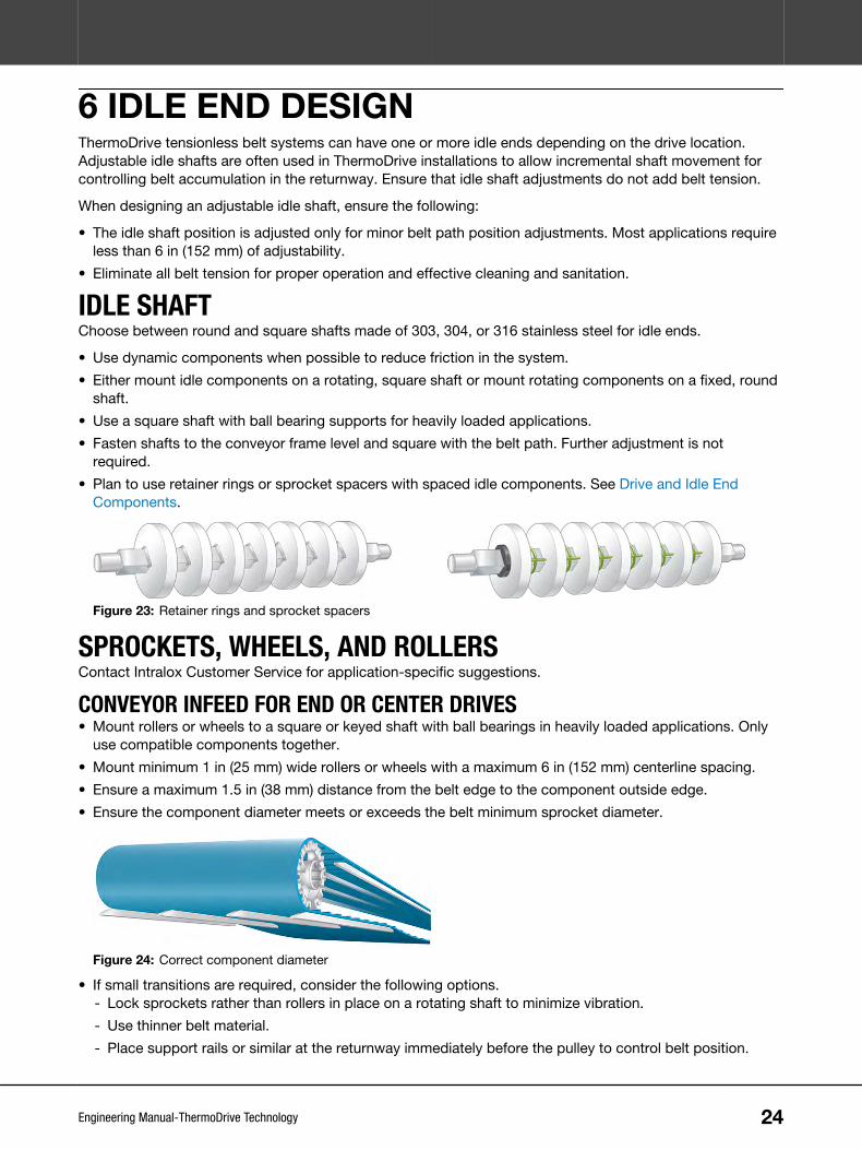
SPROCKETS, WHEELS, AND ROLLERSContact Intralox Customer Service for application-specific suggestions.
CONVEYOR INFEED FOR END OR CENTER DRIVES• Mount rollers or wheels to a square or keyed shaft with ball bearings in heavily loaded applications. Only
use compatible components together.
• Mount minimum 1 in (25 mm) wide rollers or wheels with a maximum 6 in (152 mm) centerline spacing.
• Ensure a maximum 1.5 in (38 mm) distance from the belt edge to the component outside edge.
• Ensure the component diameter meets or exceeds the belt minimum sprocket diameter.
Figure 24: Correct component diameter
• If small transitions are required, consider the following options.- Lock sprockets rather than rollers in place on a rotating shaft to minimize vibration.
- Use thinner belt material.
- Place support rails or similar at the returnway immediately before the pulley to control belt position.
24Engineering Manual-ThermoDrive Technology

• Use UHMW-PE materials when possible.
CONVEYOR OUTFEED FOR CENTER DRIVES• Mount sprockets with a maximum 3 in (76 mm) centerline spacing for lightly loaded applications.
• Install outside sprockets so the sprocket tooth outside edge is 0.5–1.5 in (13–38 mm) from the belt edge.
• For heavily loaded applications, consider stacked sprockets or a full-width idle roller.
• Mount sprockets to a square or keyed shaft with bearing supports that accommodate the expected shaftload. Journal bearing designs are suitable in some applications. Contact Intralox Customer Service forapplication-specific suggestions.
• Use UHMW-PE materials when possible.
HYGIENIC RECOMMENDATIONS• Ensure component materials are approved for product contact by regulatory agencies.
• Eliminate ball bearings at the idle section on an end drive or unidirectional center drive conveyor (allowed because oftensionless design).
• Choose one of the following idle end designs:
- A full-width, UHMW-PE idle roller
- UHMW-PE wheels rotating on a fixed, round 316 stainless steel shaft
- UHMW-PE wheels fixed on a rotating, square 316 stainless steel shaft with UHMW-PE bearings
• Use Intralox sprocket spacers for the most hygienic spaced sprocket or wheel solution.
• Design the adjustable idle section to be mounted with minimal fasteners, threaded rods, and tools. For example, include equallyspaced slots for idle shaft mounting to ensure easy disassembly or removal during cleaning and sanitation.
• Ensure CIP systems are designed so idle shaft components receive full spray coverage. See General Clean-in-PlaceRecommendations for more information.
6 IDLE END DESIGN
25Engineering Manual-ThermoDrive Technology
7 CARRYWAY DESIGNCarryways of various materials and arrangements can support ThermoDrive belts. Design carryways as acontinuous running surface with low friction to reduce belt wear and consider the following guidelines.
• Account for thermal expansion and contraction of materials when assessing components, dimensions,and locations. See Dimension Changes.
• Calculate a full range of minimum and maximum belt dimensions. See Dimension Changes.
• Review other belt containment options. See Belt Containment.
SUPPORT RAIL GENERAL GUIDELINESIntralox recommends using UHMW-PE support rails or wearstrips for ThermoDrive belting carryway support.See Carryway and Returnway Components.
• Use rails with a smooth surface finish not exceeding Ra125 micro-inches (Ra3.2 µm).
• Ensure cut ends and edges are smooth before use.
• Avoid fasteners or keep fasteners out of the belt path by countersinking.
• Consider thermal expansion and contraction of material at operating temperatures when assessing thefollowing:- Rail lengths and fastener locations; see Dimension Changes
- Proper gap between wearstrip ends
• Avoid use of UHMW-PE products in facility temperatures above 160°F (71°C).
• Never use acetal or high-density polyethylene (HDPE) support rails.
NOTE: For retrofits, 300 Series flat stainless steel bars can be used for belt support in certain lightly loadedand low-speed applications. Do not use round supports. Contact Intralox Customer Service for application-specific suggestions.
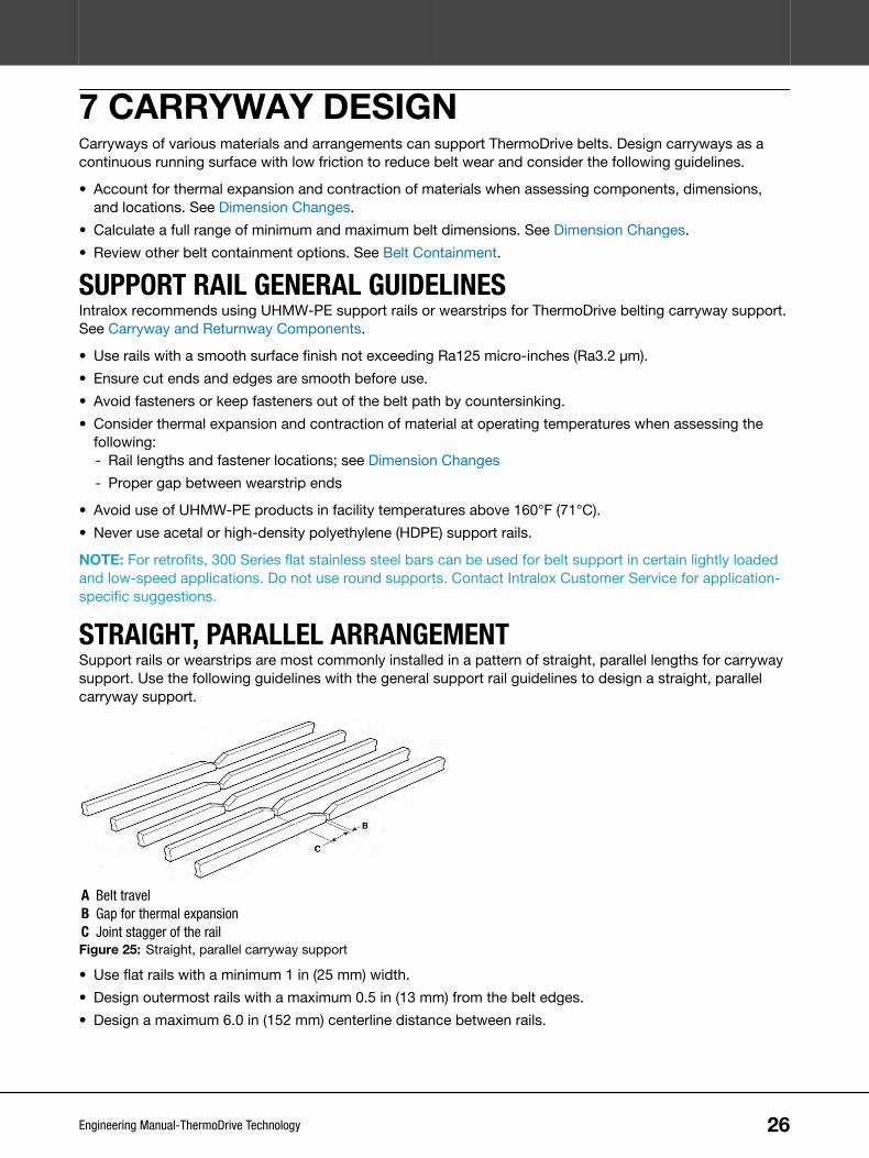
STRAIGHT, PARALLEL ARRANGEMENTSupport rails or wearstrips are most commonly installed in a pattern of straight, parallel lengths for carrywaysupport. Use the following guidelines with the general support rail guidelines to design a straight, parallelcarryway support.
A Belt travelB Gap for thermal expansionC Joint stagger of the railFigure 25: Straight, parallel carryway support
• Use flat rails with a minimum 1 in (25 mm) width.
• Design outermost rails with a maximum 0.5 in (13 mm) from the belt edges.
• Design a maximum 6.0 in (152 mm) centerline distance between rails.
26Engineering Manual-ThermoDrive Technology

• Chamfer all rail joints, cut edges, and sharp corners to eliminate catchpoints and allow smooth belttransitions.
• Chamfer the infeed and outfeed ends to prevent drive bar catchpoints and component damage.
Figure 26: Rails chamfered at a 45-degree angle
Figure 27: Wearstrip end chamfer
• Stagger the rail joints to minimize drive bar catchpoints.
• Consider using a solid UHMW-PE carryway bed at infeed or loading areas to address product impact.
• Consider using an angled (L-shaped) UHMW-PE containment rail at belt edges to assist with containment.Ensure a minimum 0.75 in (19 mm) vertical surface on angled rails.
7 CARRYWAY DESIGN
27Engineering Manual-ThermoDrive Technology

Figure 28: Alternate bridge design
Contact Intralox Customer Service for heavily loaded application-specific suggestions.
ANGLED CHEVRON ARRANGEMENTSupport rails and wearstrips can be installed in a chevron pattern for certain applications and retrofitprojects. Placing rails in this overlapping V pattern fully supports the width of the belt as it moves along thecarryway. The angled surfaces can also help remove gritty or abrasive material from the belt bottom. Use thefollowing guidelines with the general support rail guidelines to design a chevron carryway.
B
C
D
A
A Belt travelB Rail angle from centerline: 10–30°C Rail centerline spacing: maximum 5.2 in (132 mm)D Spacing between rails: minimum 0.4 in (10 mm)Figure 29: Support rails or wearstrips in chevron pattern
• Use flat rails with a minimum 1.25 in (32 mm) width and install the modified flat rails in a chevron pattern.
• Design a maximum 5.2 in (132 mm) centerline spacing between rails.
• Maintain a minimum 0.4 in (10 mm) spacing between rails at the chevron center to reduce debris buildup.
• Chamfer all rail joints, cut edges, and sharp corners to eliminate catch points and allow smooth belttransitions.
• Chamfer the infeed and outfeed rail ends to prevent drive bar catch points, vibration, and componentdamage.
Contact Intralox Customer Service for heavily loaded application-specific suggestions.
CARRYWAY WITH FLIGHTS, SIDEWALL, OR FLIGHT NOTCHESFor flighted or sidewall belts, consider the following additional carryway design guidelines.
7 CARRYWAY DESIGN
28Engineering Manual-ThermoDrive Technology

• Order belts with a minimum 1.25 in (32 mm) flight or sidewall indent.
• Contact Intralox Customer Service for center notch recommendations based on design and applicationwhen belts or flights are wider than 24 in (610 mm).
• Plan to use position limiters at flight notches on the drive end. Align the sprocket and limiter with thenotch.
• Do not use hold down shoes or similar components for belt containment purposes.
• Ensure a minimum 0.25 in (6 mm) clearance between limiter edges and flight or sidewall outside edges.
• Ensure a minimum 0.125 in (3 mm) clearance between belt and containment components.
B
A
C
A Minimum 0.25 in (6 mm)B Minimum 1.25 in (32 mm)C Minimum 0.125 in (3 mm)Figure 30: Flight and sidewall clearances
• Use belt support such as UHMW-PE hold down components at all transitions.
For flighted or sidewall belts in a Z-Conveyor (such as an incline-to-packaging application), contact IntraloxCustomer Service.
HYGIENIC RECOMMENDATIONS• Use only solid profile support rails.
• Eliminate niches, butt joints, lap joints, and the use of fasteners when possible.
• Ensure component materials are approved for product contact by regulatory agencies.
• Design carryways for easy, tool-free disassembly and reassembly during sanitation.Consider a symmetrical design to prevent errors during reassembly. For example,consider creating grooves in wearstrips for installation on round supports. Plan forcomponent thermal expansion and contraction when designing grooves.
7 CARRYWAY DESIGN
29Engineering Manual-ThermoDrive Technology

8 RETURNWAY DESIGNThe returnway of a tensionless conveyor with patented ThermoDrive technology is critical to the overalldesign. The belt is designed to be installed and naturally operate with loose belt in the returnway. A properlydesigned returnway with proper belt installation allows tensionless operation. It enables belt lifting andaccess for sanitation. It also controls storage of belt length that accumulates from load and temperaturevariations. Design the returnway using the following information.
BELT DIMENSIONSConsider thermal expansion and contraction of material when assessing rail lengths and fasteners. SeeDimension Changes for more information.
• Calculate a full range of minimum and maximum belt lengths and widths before designing belt carrywaysupport, returnway support, and containment components.
CATENARY SAGBelt accumulated in the returnway hangs loosely and assumes the shape of a curve called catenary. Thecurve dimensions are based on the distance between supports, the length of hanging belt, stiffness of thebelt, and the belt weight.
• Choose a belt length that prevents belt contact with obstacles such as drip pans, frame supports,fasteners, wiring, and other equipment.
• Use returnway support components to control the locations, lengths, and depths of sags.
MANAGING BELT ACCUMULATIONThe loose belt on a conveyor naturally accumulates in the returnway. The amount of loose belt varies basedon expansion and contraction from load and temperature changes.
Generally, the most belt accumulates in the open area immediately following the drive sprockets. Forinclined conveyors, the most belt usually accumulates in the lowest open area near the infeed returnway.These open areas often have the deepest belt sags.
A Flat conveyor belt accumulationB Incline conveyor belt accumulationFigure 31: Belt accumulation
• Calculate the correct amount of belt needed for the conveyor length. See Total Belt DimensionCalculation.
• Choose the optimal location for the deepest belt sag. Consider the location of obstacles such as drippans, frame supports, and wiring.
30Engineering Manual-ThermoDrive Technology

• Design the longest distance between returnway supports at the optimal location for deep belt sag.- Consider the distance required between components to accommodate loose belt.
- Include at least one distance between 30 in (762 mm) and 72 in (1829 mm) in most applications.
- Determine the approximate vertical clearance needed for the belt sag at each open area. See CatenarySag Clearance Reference.
- Ensure the design prevents belt contact with obstacles.
Figure 32: Catenary sag between components
Catenary Sag Clearance Referencea
Length of Open Area in the Returnway Typical Maximum Clearance Neededb, c
ft m in mm
Up to 2 ft 0.61 4.0 102
3 ft 0.91 6.0 152
4 ft 1.22 9.0 229
5 ft 1.52 12.0 305
6 ft 1.83 15.0 381
a If the returnway is not horizontal, contact Intralox Customer Service for clearance information.b For belts with flights or sidewalls, add the height of the tallest accessory to the typical maximum clearance needed dimension.c The typical maximum clearance needed allows for a range of possible belt sags when the belt is the correct length for optimal operation. The actual clearanceneeded can be less based on the application.
Figure 33: Catenary sag
A: Length of open area between components
B: Typical maximum clearance needed
• Expect the sag depths to vary during conveyor operation based on belt speed, temperature changes, andproduct load changes.
NOTE: To verify tensionless belt operation, stop the conveyor and shift the belt sideways at the infeed idleend. The belt should move without effort.
8 RETURNWAY DESIGN
31Engineering Manual-ThermoDrive Technology

RETURNWAY SUPPORT GUIDELINESA conveyor returnway can include various framework styles with components such as rollers, intermittentwear shoes, and continuous rails. ThermoDrive tensionless belt systems can use a combination ofcontinuous and intermittent support. Depending on the conveyor, multiple lengths of open space can berequired to store the belt properly. Sag does not always distribute evenly across unsupported areas. SeeCatenary Sag.
Depending on the application, returnway support components can be dynamic, such as rollers, or static,such as shoes or rails.
A RollerB Wear shoeC Continuous railFigure 34: Returnway support components
INTERMITTENT SUPPORT (WEAR SHOES AND ROLLERS)• Mount belt support components that span the full belt width when possible.
• Design components with a maximum 12 in (305 mm) lateral centerline spacing.
• Design supports with a maximum 72 in (1829 mm) distance along the conveyor length for mostapplications. For example, design a support every 36 in (914 mm) along the returnway with one 48–72 in(1219–1829 mm) unsupported area for belt accumulation.
A Maximum 72 in (1829 mm)Figure 35: Correct support spacing
• Ensure all belt bends are equal to or larger than the minimum belt backbend diameter. See Belts.
8 RETURNWAY DESIGN
32Engineering Manual-ThermoDrive Technology

• Use flanged rollers or shoes to provide support and laterally contain the belt. See Belt Containment.
CONTINUOUS RAILS• Design support rails with a maximum 12 in (305 mm) lateral centerline distance between rails.
• Design outermost rails 2–3 in (51–76 mm) inside the belt edge for most belts. See Returnway with Flightsor Sidewalls.
• Include a minimum of one (1) 30 in (762 mm) area between continuous rail ends to accommodate beltaccumulation. See Managing Belt Accumulation.
• Consider using rollers or shoes with rails.
Figure 36: Correct lateral centerline distance between support rails
HYGIENIC RECOMMENDATIONS• Use UHMW-PE returnway components approved for product contact by regulatory agencies.
Use solid UHMW-PE rollers without ball bearings for returnway support. These minimize belt and component contact and thenumber of components.
• Use UHMW-PE support wheels for wide belt applications that are unsuitable for full-width idle rollers.
• Eliminate niches, butt joints, lap joints, and the use of fasteners when possible.
• Strive for designs that allow easy, tool-free disassembly and reassembly during sanitation.
RETURNWAY WITH FLIGHTS OR SIDEWALLSConsider these additional returnway design guidelines for belts with flights, sidewalls, or flight notches.
NOTE: Contact Intralox Customer Service for center notch recommendations based on design andapplication when belts or flights are wider than 24 in (610 mm).
Figure 37: Returnway with flights
• Order belts with a minimum 1.25 in (32 mm) flight or sidewall indent.
8 RETURNWAY DESIGN
33Engineering Manual-ThermoDrive Technology

• Consider using continuous support rails at belt edges for returnway support.- Chamfer the support rail infeed and outfeed ends to eliminate catchpoints.
- Design support rails and other components with adequate clearance from flight and sidewall edges.
A
B C
A D
B C
A Minimum 0.25 in (6 mm)B Minimum 1.25 in (32 mm)C Minimum 0.125 in (3 mm)D Minimum 0.25 in (6 mm)Figure 38: Minimum clearances for support rails and other components
• Design containment components with a minimum 0.125 in (3 mm) clearance from the belt edge. See BeltContainment.
• Do not allow flights or sidewalls to contact returnway rails or components.
• For wider belts, use belt support such as UHMW-PE hold down components at all transitions.
NOTE: For flighted or sidewall belts used in a Z-Conveyor (such as an incline-to-packaging application),contact Intralox Customer Service.
8 RETURNWAY DESIGN
34Engineering Manual-ThermoDrive Technology

9 BELT CONTAINMENTThermoDrive belts are guided along the carryway and returnway to control lateral movement. Full-width beltdrive bars on the belt bottom surface provide lateral rigidity. Therefore, conveyor components such ascontainment rails, blocks, or flanged rollers are only needed along the belt edges.
NOTE: In some retrofit applications, conveyor frames can be used to contain the belt. Consider addingUHMW-PE components to framework to minimize belt wear. Contact Intralox Customer Service forapplication-specific suggestions.
• Consider thermal expansion and contraction of material when assessing component dimensions andlocations. See Belt Dimension Change Considerations.
• Calculate a full range of minimum and maximum belt dimensions based on facility and operatingtemperatures and belt load.
• Use the largest belt dimensions to design a minimum 0.125 in (3 mm) clearance between containmentcomponents and the belt edge on each side of the belt.
C D
A AB
A Minimum 0.125 in (3 mm) clearanceB Belt widthC Carryway support railsD Containment componentsFigure 39: Correct clearance between containment components and belt edges
• Use components made of UHMW-PE with a smooth surface finish not exceeding Ra125 micro-inches(Ra3.2 microns) to minimize belt friction.
• Never use components made of acetal or HDPE.
• At the carryway, mount belt containment blocks near the idle shaft.- Add more containment components along the conveyor length a maximum 6 ft (1.8 m) distance apart.
35Engineering Manual-ThermoDrive Technology

• At the returnway, mount belt containment blocks or flanged rollers near the idle shaft.- Add more containment components along the conveyor length a maximum 6 ft (1.8 m) distance apart.
- When using flanged rollers, ensure a minimum 0.75 in (19 mm) flange height at belt edges. This providesa minimum 0.5 in (13 mm) vertical height above the belt surface.
- See Carryway and Returnway Components.
- Ensure inside flange edges are chamfered to minimize belt wear.
A Minimum 0.75 (19 mm) clearanceB Required chamferFigure 40: Minimum clearance and required chamfer
• Use full-length or angled (L-shaped) containment rails or long containment blocks for applications withside loading or product diverting.
• Design containment blocks and rails with the following minimum specifications to reduce belt wear andfriction:- 6 in (150 mm) length and 0.25 in (6.4 mm) chamfer on infeed and outfeed ends
- 0.031 in (0.8 mm) corner radius to avoid belt edge damage
- 0.5 in (13 mm) vertical height above the belt edge
B
A
D
C
A Minimum 6 in (150 mm)B Minimum 0.25 in (6.4 mm)C Minimum 0.031 in (0.8 mm)D Minimum 0.5 in (13 mm)Figure 41: Minimum specifications for containment blocks and rails
• Countersink all fasteners below containment component surfaces to prevent belt contact with fasteners.
• Design vertical containment surfaces parallel to the carryway and perpendicular to the belt edge.
9 BELT CONTAINMENT
36Engineering Manual-ThermoDrive Technology

HYGIENIC RECOMMENDATIONS• Eliminate niches, butt joints, lap joints, and the use of fasteners when possible.
• Mount components for easy, tool-free disassembly and reassembly during sanitation. For example, integrate containment intocarryway guide rails, mount components on frame slots, or design them to fit on round bars in the frame.
• Design all concave cuts with a minimum 0.125 in (3 mm) internal radius.
• Ensure component materials are approved for product contact by regulatory agencies.
9 BELT CONTAINMENT
37Engineering Manual-ThermoDrive Technology

10 TROUGHED CONVEYORSThermoDrive belts can be troughed easily for product control while maintaining the benefits of the patentedtensionless, sprocket-driven operation. There are several possible configurations. Contact Intralox CustomerService for application-specific suggestions.
Design troughed conveyors using the design guidelines provided in this manual. Also incorporate thefollowing trough-specific guidelines.
For information on the ThermoDrive Trough Converter, see Trough Converter.
Figure 42: UHME-PE containment rails
Use UHMW-PE containment rails or blocks for lateral belt containment.See Belt Containment.
Figure 43: Correct transition distance
Ensure the transition distance (distance from end of troughed conveyorto drive or idle shaft center) is adequate. The transition distance mustbe a minimum of 1.5 times the belt width. Proper transition distanceminimizes strain on belt edges and reduces belt friction.
CONTINUOUS CARRYWAY FOR BELTS WITH NO TROUGHGROOVE
Figure 44: Belt with no trough groove
• Minimum belt width and trough radius: numbers are interdependent; contact Intralox Customer Service.
• Wearstrips: 3–6 in (76–152 mm) centerline spacing
• Maximum containment block spacing: 6–8 ft (1.8–2.4 m)
• Minimum transition length: 1.5 x belt width
38Engineering Manual-ThermoDrive Technology

V-SHAPED CARRYWAY FOR BELTS WITH ONE TROUGHGROOVE
Figure 45: V-shaped carryway
• Minimum belt width: 10 in (254 mm)
• Standard groove width: 2.0 in (51 mm)
• Base belt thickness at groove: 2 mm
• Maximum angle from horizontal: 30 degrees
• Maximum containment block spacing: 6–8 ft (1.8–2.4 m)
• Minimum transition length: 1.5 x belt width
• Available with notched flights
For information on S8126 troughed conveyor belt, see S8126 Flat Top E (6.0 mm). Contact IntraloxCustomer Service for S8126 conveyor design and installation specifics.
U-SHAPED CARRYWAY FOR BELTS WITH TWO TROUGHGROOVES
Figure 46: U-shaped carryway
• Standard groove width: 2.0 in (51 mm)
• Base belt thickness at groove: 2 mm
• Minimum groove center distance: 10 in (254 mm)
• Minimum section length: 4 in (102 mm)
• Maximum angle from horizontal: 60°
• Maximum containment block spacing: 6–8 ft (1.8–2.4 m)
• Minimum transition length: 1.5 x belt width
• Available with notched flights
For trough groove and drive bar removal specifics, see Belt Features.
10 TROUGHED CONVEYORS
39Engineering Manual-ThermoDrive Technology

11 DIMENSION CHANGESOVERVIEWChanges in load and temperature expand and contract belts and components during operation.
• Ensure the correct initial belt and component dimensions when ordering.
• Consider the belt and component dimension changes (length and width) when designing the belt path.Cold temperatures can cause over-tensioning and excessive shaft load. Hot temperatures can cause beltstorage or contact issues.
BELT DIMENSION CHANGE CONSIDERATIONS• Design containment components with adequate clearance from the belt.
• Provide adequate returnway supports to accommodate the weight, depth, and location of beltaccumulation during expansion.
• Calculate the belt weight based on dimensions using belt data. See Belts.
• Ensure returnway obstacles such as drip pans, frame supports, fasteners, and wiring do not contact thebelt at maximum and minimum sizes.
• Ensure belt accumulation or obstacles do not apply tension to the belt.
COMPONENT DIMENSION CHANGE CONSIDERATIONS• Ensure holes are slotted to allow for component movement in relation to fasteners.
• Leave adequate clearance between components.
• Consider that belts and components change simultaneously.
TOTAL BELT DIMENSION CALCULATIONUse the steps here to determine the total belt length for your horizontal conveyor. Contact Intralox CustomerService for calculation help.
1. Calculate the belt needed between each unsupported area in the returnway.Unsupported additional returnway belt length formula: (2.66 × S2) / D = X
Where:
X = Additional belt length at chosen sag, in (mm)
S = desired sag depth, in (mm)
D = Distance between chosen supports, in (mm)
2. Add all Unsupported additional returnway belt lengths (X) in the returnway to calculate the Additionalreturnway belt needed (X2).
3. Use the Additional returnway belt needed (X2) to calculate the Total belt length recommended forinstallation.Total belt length formula: 2CL + (2AC) + X2 = TBL
Where:
TBL = Total belt length, in (mm)
CL = Conveyor length from sprocket center to sprocket center, in (mm)
AC = Belt wrap at end drive sprocket or rollers, in (mm)
X2 = Additional returnway belt needed, in (mm)
40Engineering Manual-ThermoDrive Technology

4. Consider all temperature changes during the full operating cycle (downtime, production, sanitation) tocalculate minimum and maximum belt dimensions. See Thermal Expansion and Contraction Calculations.
5. Contact Intralox Customer Service for suggested extra belt length for splicing and repair.
THERMAL EXPANSION AND CONTRACTION CALCULATIONSAlways consider thermal expansion and contraction when choosing conveyor component materials,purchasing belt, and making design choices. Dimension changes depend on product material, temperaturechanges during operation, and overall dimensions.
Use the following information to calculate minimum and maximum belt or component dimension changesduring the full operating cycle (downtime, production, sanitation).
CALCULATE FACILITY TEMPERATURE CHANGEUse the following formula to calculate overall facility temperature change.
Facility temperature change formula: T2 - T1 = T3
Where:
T3 = temperature change, °F (°C)
T2 = application belt temperature, °F (°C)
T1 = 72 (22), Intralox belt production temperature °F (°C)
CALCULATE MATERIAL DIMENSION CHANGESUse the following formula to calculate the dimension change of belts, support rails, wearstrip, or otherplastic containment components.
Dimension change formula: D x T3 x CLTE = Δ
Where:
Δ = dimension change, imperial (metric)
D = initial dimension (length or width) when leaving Intralox, imperial (metric)
T3 = temperature change, °F (°C)
CLTE = Coefficient of Thermal Expansion
Coefficients of Linear Thermal Expansion (CLTE)Material Imperial (µin/in-°F) Metric (µm/m-°C)Cold Use 94 170
Dura 167 300
HTL 83 150
Polyurethane 83 150
PUR A23 50 90
UHMW-PE 110 198
For example, calculate the change in length of a 100 ft (30 m) long ThermoDrive S8050 polyurethane beltoperating with an average belt temperature of 45°F (7°C).
Calculations Imperial and MetricTemperature change (T3 = T2-T1) 45°F - 72°F = -27°F (7°C-22°C = -15°C)
Initial belt length (D) 100 ft = 1200 in (30 m)
11 DIMENSION CHANGES
41Engineering Manual-ThermoDrive Technology

Calculations Imperial and MetricLength change (Δ=D x T3 x CTE) 1200 in x -27°F x 83 (µin/in-°F) = -2689200 µin = -2.6892 in [30 m x
-15°C x 150 (µm/m-°C) = -67500 µm = -67.5 mm]
BELT ELONGATION UNDER LOADAll belts temporarily strain or stretch with load applied. The extent of change depends on belt material, load,and overall belt length.
11 DIMENSION CHANGES
42Engineering Manual-ThermoDrive Technology

12 BELT SELECTIONVISUAL OVERVIEW
Belts
Series 8026 Flat TopPolyurethane (5.3 mm)
Series 8026 Flat TopPolyurethane (6.0 mm)
Series 8026 EmbeddedDiamond Top Polyurethane
(6.3 mm)
Series 8026 Nub TopPolyurethane (6.3 mm)
Series 8026 Nub TopPolyurethane (7.4 mm)
Series 8026 Flat Top ColdUse (6.0 mm)
Series 8050 Flat TopPolyurethane (7.0 mm)
Series 8050 EmbeddedDiamond Top Polyurethane
(7.5 mm)
Series 8050 Nub TopPolyurethane (8.0 mm)
Series 8050 Flat Top ColdUse (7.0 mm)
Series 8050 Flat Top Dura(7.0 mm)
Series 8050 Flat Top HighTemperature Heavy Load
(HTL) (7.0 mm)
Series 8050 Flat TopExtreme Temperature (XT)
(7.0 mm)
Series 8050 Ribbed V-Top™Polyurethane (9.5 mm)
Series 8126 Flat TopPolyurethane (6.0 mm)
Series 8050 Flat TopPolyurethane A23 E (7.0
mm)
Series 8140 Flat TopPolyurethane A23 E (10.5
mm)
43Engineering Manual-ThermoDrive Technology

Belt Joining Options
Prepared ends Endless ThermoLace™ Metal Lace
Belt Fabrications
90-Degree Flights 75-Degree Flights Scoop Flights Short Top Scoop Flights
Perforations Trough Grooves Drive Bar Removal
Flight Gussets Sidewalls V-Guide
BELT SELECTION CONSIDERATIONSTo select the correct ThermoDrive belt, consider all options.
1. Choose a basic belt. Each belt description indicates several characteristics.For example, S8050 Flat Top (7.0 mm) Polyurethane indicates the following belt characteristics.• The belt material is polyurethane.
• The belt style (surface texture) is Flat Top.
• The belt series is 8050, which has 50-mm drive pitch (distance between each drive bar).
• The belt thickness is 7.0 mm. The drive bar, material, and surface texture determines thickness.
2. Based on the belt description, choose other specifics. Not all belts have the same options.• Belt joining options
• Belt features such as trough grooves, drive bar removal, or perforations
• Belt accessories such as flights, sidewalls, v-guide, and gussets
3. Review the following belt selection considerations and specific belt product information to choose thebest options for your application. Contact Intralox Customer Service for application-specific suggestions.
CHOOSE MATERIALThermoDrive belts and accessories are available in standard polyurethane and special application materials.
Polyurethane—most commonly used material; available in blue or white
12 BELT SELECTION
44Engineering Manual-ThermoDrive Technology

• Used in continuous temperature ranges from 20°F (-7°C) to 140°F (60°C)
• Depending on belt series, style, and thickness, offers belt strengths from 175 lb/ft (260 kg/m) to 420 lb/ft(625 kg/m)
Cold Use (CU)—designed for ambient to very cold temperatures; provides peak performance in colderenvironments
• Used in applications with temperature ranges from -30°F (-34°C) to 75°F (24°C)
• Depending on belt series and thickness, offers a belt strength of 150 lb/ft (223 kg/m) to 225 lb/ft (335kg/m)
Dura—designed for heavy loading in high and low temperatures
• Used with temperature ranges from 20°F (-7°C) to 140°F (60°C); contact Intralox for use in temperaturesbelow or above these
• Offers belt strengths up to 950 lb/ft (1414 kg/m)
High Temperature Heavy Load (HTL)—employed for high temperatures and heavy loads
• Used in applications with temperature ranges from 60°F (15°C) to 210°F (99°C)
• Offers belt strengths up to 1056 lb/ft (1572 kg/m)
XT—designed for extreme temperatures (high or low)
• Used in applications with temperature ranges from -4°F (-20°C) to 170°F (77°C)
• Offers belt strengths up to 800 lb/ft (1190 kg/m)
Polyurethane A23 —designed to perform well in hydrolysis prone applications
• Used in applications with temperature ranges from 40°F (5°C) to 212°F (100°C)
• Offers belt strengths up to 540 lb/ft (803 kg/m)
CHOOSE BELT STYLE (SURFACE TEXTURE)ThermoDrive belts and accessories are available in standard Flat Top surfaces and special applicationsurfaces.
Flat Top (FT)—an engineered matte surface finish optimized for efficient product release and cleanability
Embedded Diamond Top (EDT)—a cleanable, embedded diamond surface texture with superior productrelease characteristics
Nub Top™ (NT)—a raised top profile that provides grip characteristics with some products and releasecharacteristics with other products
Ribbed V-Top™ (RVT)—a top profile with an overlapping pattern of raised Vs and ribs that improve productrelease and removal at discharge; enhances incline conveyance capabilities for bulk product up to 30°without need for flights
CHOOSE BELT SERIESThermoDrive belts are available with 26-mm or 50-mm nominal drive pitch. A shorter pitch reduces sprocketdiameter and the space required for product transfers. A longer pitch correlates with larger transfers andsprocket diameters, thicker belts, and increased belt pull.
Series 8026 and 8126 belts—26-mm drive pitch; often used for lightly loaded applications and productsrequiring short transfer distances
Series 8050 belts—50-mm drive pitch; often used for moderate to heavily loaded applications where biggertransfer distances are acceptable
12 BELT SELECTION
45Engineering Manual-ThermoDrive Technology

Series 8140 belts—40-mm drive pitch; used in light to moderately loaded applications where bigger transferdistances are acceptable
CHOOSE BELT JOINING OPTIONSThermoDrive belt ends have various joining options: splicing, ThermoLace, or metal lacing. The strength ofthe joining option chosen effects overall belt strength. See Belt Joining Options.
CHOOSE BELT FEATURES AND ACCESSORIESSpecial belt features are available for unique applications.
Perforations—belt hole pattern most often used for hygienic dewatering applications
Trough grooves—drive bar removal along the belt length that completely removes drive bar and 0.039 in (1mm) of the belt cover; designed to enable a deep trough for severe trough applications; not required for alltroughed conveyors
Drive bar removal—drive bar removal along the belt length that leaves about 0.005 in (0.13 mm) of drive barand full cover thickness
Various accessories are available on certain belts.
Flights—vertical accessory hygienically joined across the belt width available in various types, heights,thicknesses, and styles; contributes to reliable conveyance on incline or elevator applications
Flight gussets—angled flight support joined to the flight to increase flight rigidity; often used in heavilyloaded applications
Synchronized sidewall—vertical accessory hygienically joined along belt length available in various heights,thicknesses, and styles; designed for effective product containment
V-Guide—vertical accessory hygienically joined along belt length; useful as a hold down for z-conveyortransitions and returnway containment
For details, see Belt Features and Belt Accessories.
Belts, Features, and Accessories Availability ReferenceMaterial Polyurethane Cold Use Dura HTL XT PUR A23
Color Blue White Blue Blue Natural Blue BlueStyle FT EDT NT RVT FT FT FT FT FT FT
Series 8026
5.3 mm BTF BTF
6.0 mm BTF BTF BTF
6.3 mm BTF BF
7.4 mm BTF
Series 8050
7.0 mm BPTFS BPTFS BTFS BTF BT BT BTFS
7.5 mm BTFS
8.0 mm BTF
9.5 mm B
Series 8126
6.0 mm B
Series 8140
10.5 mm BFSV
FT—Flat Top; EDT—Embedded Diamond Top; NT—Nub Top; RVT—Ribbed V-Top
12 BELT SELECTION
46Engineering Manual-ThermoDrive Technology
B—Belt available in designated series, thickness, material, color, and style
P—Perforations available; T—Trough grooves available; F—Flights available; S—Sidewall available; V-Guideavailable
For details, see Belt Features and Belt Accessories.
12 BELT SELECTION
47Engineering Manual-ThermoDrive Technology

13 BELTSS8026 Flat Top E (5.3 mm)
in mm
Pitch 1.00 26
Overall Thickness 0.209 5.3
Minimum Width 1 25
Maximum Width 72 1829
Minimum Backbend Diameter 2.50 64
Minimum Sprocket Diameter (6T) 2.0 51
Open Area (seamless surface) 0%
Available Joining Options prepared ends, endless,metal lace
Available Colors blue, white
Product Notes• Contact Intralox for precise belt measurements and stock
status before designing equipment or ordering a belt.• Engineered matte surface is optimized for efficient product release
and cleanability.
• Available with flights.
• See Material Compliance for compliance details.
0.071"(1.8 mm)
1.00" NOM.(26 mm) 0.209"
(5.3 mm)
Belt Data
Belt MaterialBelt Strengtha Temperature Range (continuous) Belt Weight
lb/ft kg/m °F °C lb/ft2 kg/m2
Polyurethane 175 260 20–140 -7–60 0.57 2.78
a With sprockets spaced on 3 in (76 mm) centers; Consider using stacked sprockets for optimal operational performance in heavily loaded applications; Forcontinuous use over 100°F (38°C), contact Intralox Customer Service for actual belt strength.
48Engineering Manual-ThermoDrive Technology

S8026 Flat Top E (6.0 mm)in mm
Pitch 1.00 26
Overall Thickness 0.236 6.0
Minimum Width 1 25
Maximum Width 72 1829
Minimum Backbend Diameter 3.25 82
Minimum Sprocket Diameter (10T) 3.2 81
Open Area (seamless surface) 0%
Available Joining Options prepared ends, endless,ThermoLace, metal lace
Available Colors blue, white
Product Notes• Contact Intralox for precise belt measurements and stock
status before designing equipment or ordering a belt.• Engineered matte surface is optimized for efficient product release
and cleanability.
• Available with flights.
• See Material Compliance for compliance details.
0.098"(2.5 mm)
1.00" NOM.(26 mm)
0.236"(6 mm)
Belt Data
Belt MaterialBelt Strengtha Temperature Range (continuous) Belt Weight
lb/ft kg/m °F °C lb/ft2 kg/m2
Polyurethane 300 446 20–140 -7–60 0.69 3.35
a With sprockets spaced on 3 in (76 mm) centers; Consider using stacked sprockets for optimal operational performance in heavily loaded applications; Forcontinuous use over 100°F (38°C), contact Intralox Customer Service for actual belt strength.
13 BELTS
49Engineering Manual-ThermoDrive Technology

S8026 Embedded Diamond Top E (6.3 mm)in mm
Pitch 1.00 26
Overall Thickness 0.248 6.3
Minimum Width 1 25
Maximum Width 72 1829
Minimum Backbend Diameter 3.25 82
Minimum Sprocket Diameter (10T) 3.2 81
Open Area (seamless surface) 0%
Available Joining Options prepared ends, endless,ThermoLace, metal lace
Available Colors blue
Product Notes• Contact Intralox for precise belt measurements and stock
status before designing equipment or ordering a belt.• Includes a proven Embedded Diamond Top profile to provide
superior release characteristics in applications where productrelease requirements exceed Flat Top characteristics
• Available with flights.
• ThermoLace is Flat Top on each side of hinge rod.
• If ThermoLace is the selected joining method, the belt thickness is6.3 mm. The S8026 ThermoLace thickness is 6.0 mm. This createsa step due to thickness difference.
• See Material Compliance for compliance details.0.108"
(2.7 mm)
1.00" NOM.(26 mm)
0.246"(6.3 mm)
Belt Data
Belt MaterialBelt Strengtha Temperature Range (continuous) Belt Weight
lb/ft kg/m °F °C lb/ft2 kg/m2
Polyurethane 300 446 20–140 -7–60 0.69 3.37
a With sprockets spaced on 3 in (76 mm) centers; Consider using stacked sprockets for optimal operational performance in heavily loaded applications; Forcontinuous use over 100°F (38°C), contact Intralox Customer Service for actual belt strength.
13 BELTS
50Engineering Manual-ThermoDrive Technology

S8026 Nub Top™ (6.3 mm)in mm
Pitch 1.00 26
Overall Thickness 0.238 6.04
Minimum Width 1 25
Maximum Width 24 610
Minimum Backbend Diameter 2.5 64
Minimum Sprocket Diameter (6T) 2.0 51
Open Area (seamless surface) 0%
Available Joining Options prepared ends, endless
Available Colors blue
Product Notes• Contact Intralox for precise belt measurements and stock
status before designing equipment or ordering a belt.• Provides excellent product grip for moderate incline conveyance;
offers superior release of certain products.
• Available with 4-mm flights.
• See Material Compliance for compliance details.
Belt Data
Belt MaterialBelt Strengtha Temperature Range (continuous) Belt Weight
lb/ft kg/m °F °C lb/ft2 kg/m2
Polyurethane 96 142.85 20–140 -7–60 0.533 2.6
a With sprockets spaced on 3 in (76 mm) centers; Consider using stacked sprockets for optimal operational performance in heavily loaded applications; Forcontinuous use over 100°F (38°C), contact Intralox Customer Service for actual belt strength.
13 BELTS
51Engineering Manual-ThermoDrive Technology

S8026 Nub Top™ E (7.4 mm)in mm
Pitch 1.00 26
Overall Thickness 0.291 7.4
Minimum Width 1 25
Maximum Width 72 1829
Minimum Backbend Diameter 3.25 83
Minimum Sprocket Diameter (10T) 3.2 81
Open Area (seamless surface) 0%
Available Joining Options prepared ends, endless,ThermoLace, metal lace
Available Colors blue
Product Notes• Contact Intralox for precise belt measurements and stock
status before designing equipment or ordering a belt.• Provides excellent product grip for moderate incline conveyance;
offers superior release of certain products.
• Available with flights.
• ThermoLace is Flat Top on each side of hinge rod.
• If ThermoLace is the selected joining method, the belt thickness is7.4 mm. The S8026 ThermoLace thickness is 6.0 mm. This createsa step due to thickness difference.
• See Material Compliance for compliance details.
1.00 in(26 mm)
.291 in(7.4 mm)
.055 in(1.4 mm)
.153 in(3.9 mm)
Belt Data
Belt MaterialBelt Strengtha Temperature Range (continuous) Belt Weight
lb/ft kg/m °F °C lb/ft2 kg/m2
Polyurethane 300 446 20–140 -7–60 0.754 3.68
a With sprockets spaced on 3 in (76 mm) centers; Consider using stacked sprockets for optimal operational performance in heavily loaded applications; Forcontinuous use over 100°F (38°C), contact Intralox Customer Service for actual belt strength.
13 BELTS
52Engineering Manual-ThermoDrive Technology
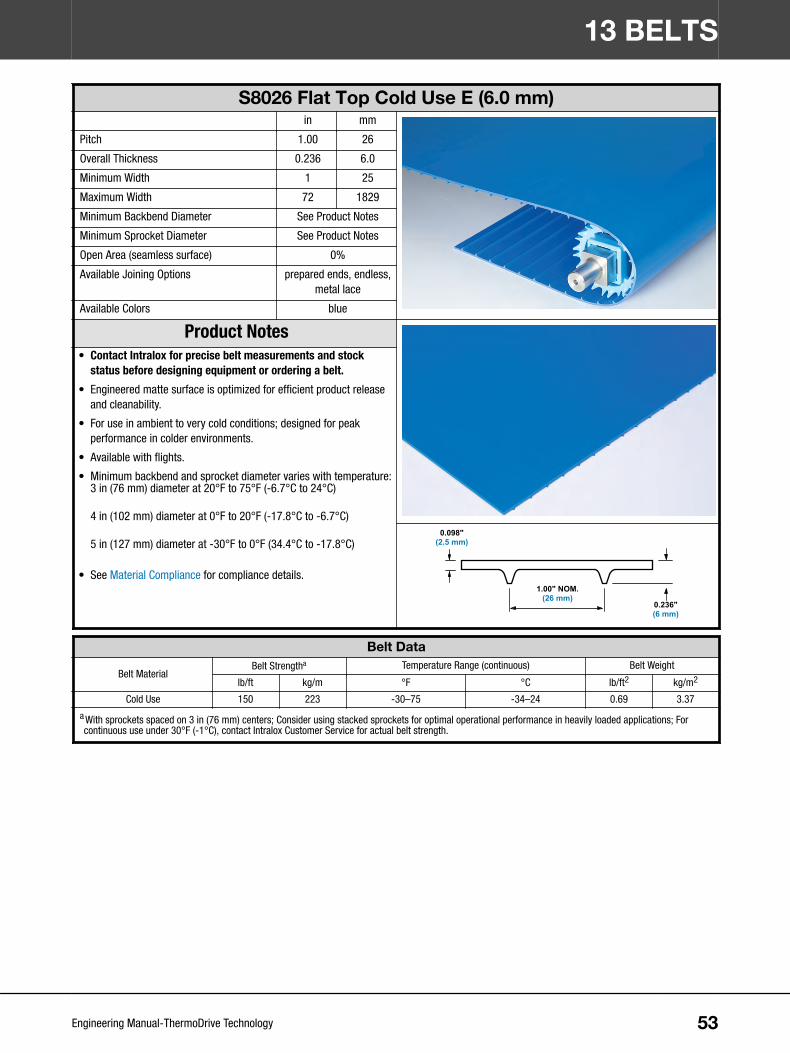
S8026 Flat Top Cold Use E (6.0 mm)in mm
Pitch 1.00 26
Overall Thickness 0.236 6.0
Minimum Width 1 25
Maximum Width 72 1829
Minimum Backbend Diameter See Product Notes
Minimum Sprocket Diameter See Product Notes
Open Area (seamless surface) 0%
Available Joining Options prepared ends, endless,metal lace
Available Colors blue
Product Notes• Contact Intralox for precise belt measurements and stock
status before designing equipment or ordering a belt.• Engineered matte surface is optimized for efficient product release
and cleanability.
• For use in ambient to very cold conditions; designed for peakperformance in colder environments.
• Available with flights.
• Minimum backbend and sprocket diameter varies with temperature:3 in (76 mm) diameter at 20°F to 75°F (-6.7°C to 24°C)
4 in (102 mm) diameter at 0°F to 20°F (-17.8°C to -6.7°C)
5 in (127 mm) diameter at -30°F to 0°F (34.4°C to -17.8°C)
• See Material Compliance for compliance details.
0.098"(2.5 mm)
1.00" NOM.(26 mm)
0.236"(6 mm)
Belt Data
Belt MaterialBelt Strengtha Temperature Range (continuous) Belt Weight
lb/ft kg/m °F °C lb/ft2 kg/m2
Cold Use 150 223 -30–75 -34–24 0.69 3.37
a With sprockets spaced on 3 in (76 mm) centers; Consider using stacked sprockets for optimal operational performance in heavily loaded applications; Forcontinuous use under 30°F (-1°C), contact Intralox Customer Service for actual belt strength.
13 BELTS
53Engineering Manual-ThermoDrive Technology

S8050 Flat Top E (7.0 mm)in mm
Pitch 1.96 50
Overall Thickness 0.276 7.0
Minimum Width 1 25
Maximum Width 72 1829
Minimum Backbend Diameter 4.0 102
Minimum Sprocket Diameter (6T) 4.0 102
Open Area (seamless surface) 0%
Available Joining Options prepared ends, endless,ThermoLace, metal lace
Available Colors blue, white
Product Notes• Contact Intralox for precise belt measurements and stock
status before designing equipment or ordering a belt.• Engineered matte surface is optimized for efficient product release
and cleanability.
• Available with flights and Synchronized Sidewalls.
• See Material Compliance for compliance details.
0.118"(3 mm)
1.96" NOM.(50 mm)
0.276"(7 mm)
Belt Data
Belt MaterialBelt Strengtha Temperature Range (continuous) Belt Weight
lb/ft kg/m °F °C lb/ft2 kg/m2
Polyurethane 420 625 20–140 -7–60 0.89 4.35
a With sprockets spaced on 3 in (76 mm) centers; Consider using stacked sprockets for optimal operational performance in heavily loaded applications; Forcontinuous use over 100°F (38°C), contact Intralox Customer Service for actual belt strength.
13 BELTS
54Engineering Manual-ThermoDrive Technology

S8050 Embedded Diamond Top E (7.5 mm)in mm
Pitch 1.96 50
Overall Thickness 0.296 7.5
Minimum Width 1 25
Maximum Width 72 1829
Minimum Backbend Diameter 4.0 102
Minimum Sprocket Diameter (6T) 4.0 102
Open Area (seamless surface) 0%
Available Joining Options prepared ends, endless,ThermoLace, metal lace
Available Colors blue
Product Notes• Contact Intralox for precise belt measurements and stock
status before designing equipment or ordering a belt.• Includes a proven Embedded Diamond Top profile to provide
superior release characteristics in applications where productrelease requirements exceed Flat Top characteristics.
• Available with flights and Synchronized Sidewalls.
• ThermoLace is Flat Top on each side of hinge rod.
• If ThermoLace is the selected joining method, the belt thickness is7.5 mm. The S8050 ThermoLace thickness is 7.0 mm. This createsa step due to thickness difference.
• See Material Compliance for compliance details.0.138 in(3.5 mm)
1.96 in NOM.(50 mm)
0.296 in(7.5 mm)
Belt Data
Belt MaterialBelt Strengtha Temperature Range (continuous) Belt Weight
lb/ft kg/m °F °C lb/ft2 kg/m2
Polyurethane 420 625 20–140 -7–60 0.89 4.34
a With sprockets spaced on 3 in (76 mm) centers; Consider using stacked sprockets for optimal operational performance in heavily loaded applications; Forcontinuous use over 100°F (38°C), contact Intralox Customer Service for actual belt strength.
13 BELTS
55Engineering Manual-ThermoDrive Technology

S8050 Nub Top E (8.0 mm)in mm
Pitch 1.96 50
Overall Thickness 0.315 8.0
Minimum Width 1 25
Maximum Width 42 1067
Minimum Backbend Diameter 4.0 102
Minimum Sprocket Diameter (6T) 4.0 102
Open Area (seamless surface) 0%
Available Joining Options prepared ends, endless,ThermoLace, metal lace
Available Colors blue
Product Notes• Contact Intralox for precise belt measurements and stock
status before designing equipment or ordering a belt.• Provides excellent product grip for moderate incline conveyance;
offers superior release of certain products.
• Available with flights.
• ThermoLace is Flat Top on each side of hinge rod.
• If ThermoLace is the selected joining method, the belt thickness is8.0 mm. The S8050 ThermoLace thickness is 7.0 mm. This willcreate a step due to thickness difference.
• See Material Compliance for compliance details.
1.96 in NOM.(50 mm)
0.315 in(8.0 mm)
0.115 in(2.92 mm)
0.043 in(1.09 mm)
Belt Data
Belt MaterialBelt Strengtha Temperature Range (continuous) Belt Weight
lb/ft kg/m °F °C lb/ft2 kg/m2
Polyurethane 420 625 20–140 -7–60 0.86 4.20
a With sprockets spaced on 3 in (76 mm) centers; Consider using stacked sprockets for optimal operational performance in heavily loaded applications; Forcontinuous use over 100°F (38°C), contact Intralox Customer Service for actual belt strength.
13 BELTS
56Engineering Manual-ThermoDrive Technology

S8050 Flat Top Cold Use E (7.0 mm)in mm
Pitch 1.96 50
Overall Thickness 0.276 7.0
Minimum Width 1 25
Maximum Width 72 1829
Minimum Backbend Diameter See Product Notes
Minimum Sprocket Diameter See Product Notes
Open Area (seamless surface) 0%
Available Joining Options prepared ends, endless,metal lace
Available Colors blue
Product Notes• Contact Intralox for precise belt measurements and stock
status before designing equipment or ordering a belt.• Engineered matte surface is optimized for efficient product release
and cleanability.
• For use in ambient to very cold conditions; designed for peakperformance in colder environments.
• Available with flights and Synchronized Sidewalls.
• Minimum backbend and sprocket diameter varies with temperature:4 in (102 mm) diameter at 20°F to 75°F (-6.7°C to 24°C)
5 in (127 mm) diameter at 0°F to 20°F (-17.8°C to -6.7°C)
6 in (152 mm) diameter at -30°F to 0°F (-34.4°C to -17.8°C)
• See Material Compliance for compliance details.
0.118"(3 mm)
1.96" NOM.(50 mm)
0.276"(7 mm)
Belt Data
Belt MaterialBelt Strengtha Temperature Range (continuous) Belt Weight
lb/ft kg/m °F °C lb/ft2 kg/m2
Cold Use 225 335 -30–75 -34–24 0.82 4.00
a With sprockets spaced on 3 in (76 mm) centers; Consider using stacked sprockets for optimal operational performance in heavily loaded applications; Forcontinuous use under 30°F (-1°C), contact Intralox Customer Service for actual belt strength.
13 BELTS
57Engineering Manual-ThermoDrive Technology

S8050 Flat Top Dura E (7.0 mm)in mm
Pitch 1.96 50
Overall Thickness 0.276 7.0
Minimum Width 1 25
Maximum Width 72 1829
Minimum Backbend Diameter 6.0 152
Minimum Sprocket Diameter (10T) 6.5 165
Open Area (seamless surface) 0%
Available Joining Options prepared ends, endless,metal lace
Available Colors blue
Product Notes• Contact Intralox for precise belt measurements and stock
status before designing equipment or ordering a belt.• Designed for heavy loading in high and low temperatures.
• Available with flights.
• Provides notable impact resistance.
• For continuous use from 0° F (-18° C) to 210° F (99° C) with theseexceptions:- For temperatures over 140° F (60° C), contact Customer
Service with application information.
- For continuous use below 20° F (-7° C), contact IntraloxCustomer Service for minimum sprocket diameter.
• See Material Compliance for compliance details.
0.118"(3 mm)
1.96" NOM.(50 mm)
0.276"(7 mm)
Belt Data
Belt MaterialBelt Strengtha Temperature Range (continuous) Belt Weight
lb/ft kg/m °F °C lb/ft2 kg/m2
Dura 950 1414 See Product Notes See Product Notes 0.73 3.56
a With sprockets spaced on 3 in (76 mm) centers; Use stacked sprockets for applications with loads greater than 50% of belt strength; For continuous use over170° F (77° C), contact Intralox Customer Service for actual belt strength.
13 BELTS
58Engineering Manual-ThermoDrive Technology

S8050 Flat Top High Temperature Heavy Load (HTL) E (7.0 mm)in mm
Pitch 1.96 50
Overall Thickness 0.276 7.0
Minimum Width 1 25
Maximum Width 72 1829
Minimum Backbend Diameter 6.0 152
Minimum Sprocket Diameter (10T) 6.5 165
Open Area (seamless surface) 0%
Available Joining Options prepared ends, endless,metal lace
Available Colors natural
Product Notes• Contact Intralox for precise belt measurements and stock
status before designing equipment or ordering a belt.• Designed specifically for high temperatures and/or heavy loads.
• For continuous use below 60°F (15°C) contact Intralox CustomerService for required minimum sprocket diameter.
• See Material Compliance for compliance details.
0.118"(3 mm)
1.96" NOM.(50 mm)
0.276"(7 mm)
Belt Data
Belt MaterialBelt Strengtha Temperature Range (continuous)b Belt Weight
lb/ft kg/m °F °C lb/ft2 kg/m2
HTL 1056 1572 60–210 15–99 0.88 4.31
a With sprockets spaced on 3 in (76 mm) centers; Use stacked sprockets for applications with loads greater than 50% of belt strength. For continuous use over170°F (77°C), contact Intralox Customer Service for actual belt strength.
b In some applications, continuous use temperatures can exceed 210°F (100°C).
13 BELTS
59Engineering Manual-ThermoDrive Technology

S8050 Flat Top XT (7.0 mm)in mm
Pitch 1.96 50
Overall Thickness 0.276 7.0
Minimum Width 1 25
Maximum Width 42 1067
Minimum Backbend Diameter 6.0 152
Minimum Sprocket Diameter (10T) 6.5 165
Open Area (seamless surface) 0%
Available Joining Options prepared ends, endless,metal lace
Available Colors blue
Product Notes• Contact Intralox for precise belt measurements and stock
status before designing equipment or ordering a belt.• Designed specifically for extreme temperatures—high or low
• See Material Compliance for compliance details.
0.118"(3 mm)
1.96" NOM.(50 mm)
0.276"(7 mm)
Belt Data
Belt MaterialBelt Strengtha Temperature Range (continuous) Belt Weight
lb/ft kg/m °F °C lb/ft2 kg/m2
XT 800 1190 -4 to 170 -20 to 77 0.88 4.31
a With sprockets spaced on 3 in (76 mm) centers; Use stacked sprockets for applications with loads greater than 60% of belt strength. For continuous use over100°F (38°C), contact Intralox Customer Service for actual belt strength.
13 BELTS
60Engineering Manual-ThermoDrive Technology

S8050 Ribbed V-Top™ E (9.5 mm)in mm
Pitch 1.96 50
Overall Thickness 0.374 9.5
Minimum Width 2 51
Maximum Width 42 1067
Minimum Backbend Diameter 4.0 102
Minimum Sprocket Diameter (10T) 6.5 165
Open Area (seamless surface) 0%
Available Joining Options prepared ends, endless,ThermoLace
Available Colors blue
Product Notes• Contact Intralox for precise belt measurements and stock
status before designing equipment or ordering a belt.• Enables bulk product conveyance on inclines up to 30 degrees
without using flights.
• Allows improved product release and removal at discharge.
• ThermoLace joint is Flat Top for up to 12 in (305 mm) across hingerod.
• Spliced joint is Flat Top for less than 1 in (25 mm) across splice.
• Splicing requires ThermoDrive Belt End Router and square spacersavailable from Intralox.
See Material Compliance for compliance details. 0.118 in(3 mm)
0.216 in(5.5 mm)
0.374 in(9.5 mm)
1.96 in NOM.(50 mm)
Belt Data
Belt MaterialBelt Strengtha Temperature Range (continuous) Belt Weight
lb/ft kg/m °F °C lb/ft2 kg/m2
Polyurethane 180 268 40–140 4–60 0.987 4.82
a With sprockets spaced on 3 in (76 mm) centers; Consider using stacked sprockets for optimal operational performance in heavily loaded applications; Forcontinuous use over 100°F (38°C), contact Intralox Customer Service for actual belt strength.
13 BELTS
61Engineering Manual-ThermoDrive Technology

S8050 Flat Top Polyurethane A23 E (7.0 mm)in mm
Pitch 1.96 50
Overall Thickness 0.276 7.0
Minimum Width 1 25
Maximum Width 72 1829
Minimum Backbend Diameter 5.2 132
Minimum Sprocket Diameter (8T) 5.2 132
Open Area (seamless surface) 0%
Available Joining Options prepared ends, endless,metal lace
Available Colors blue
Product Notes• Contact Intralox for precise belt measurements and stock
status before designing equipment or ordering a belt.• Designed to perform well in hydrolysis prone applications.
• Available with flights and sidewall.
• For continuous use from 40°F (5°C) to 212°F (100°C) with theseexceptions:- For temperatures over 140°F (60°C), contact Intralox Customer
Service with application information.
- For continuous use below 60°F (15°C), contact IntraloxCustomer Service for minimum sprocket diameter.
See Material Compliance for compliance details. 0.118"(3 mm)
1.96" NOM.(50 mm)
0.276"(7 mm)
Belt Data
Belt MaterialBelt Pulla Temperature Range (continuous) Belt Weight
lb/ft kg/m °F °C lb/ft2 kg/m2
PUR A23 540 803 See Product Notes. 0.804 3.93
a With sprockets spaced on 3 in (76 mm) centers; Consider using stacked sprockets for optimal operational performance in heavily loaded applications; Forcontinuous use over 100°F (38°C), contact Intralox Customer Service for actual belt strength.
13 BELTS
62Engineering Manual-ThermoDrive Technology

S8126 Flat Top E (6.0 mm)in mm
Pitch 1.00 26
Overall Thickness 0.236 6.0
Minimum Width 10 254
Maximum Width 24 610
Minimum Backbend Diameter 4.0 102
Minimum Sprocket Diameter (12T) 4.0 102
Open Area (seamless surface) 0%
Available Joining Options prepared ends, endless
Available Colors blue
Product Notes• Contact Intralox for precise belt measurements and stock
status before designing equipment or ordering a belt.• Engineered matte surface is optimized for efficient product release
and cleanability.
• Designed for retrofitting certain high tension troughed conveyorapplications to tensionless ThermoDrive solutions; contact IntraloxCustomer Service for details.
• For use with S8126-specific drive and idle components.
• Drive bar width is 2.4 in (62 mm).
• See Material Compliance for compliance details.
0.098"(2.5 mm)
1.00" NOM.(26 mm)
0.236"(6 mm)
Belt Data
Belt MaterialBelt Strength Temperature Range (continuous) Belt Weight
lb kg °F °C lb/ft2 kg/m2
Polyurethane 120 55 20–140 -7–60 0.62 3.04
13 BELTS
63Engineering Manual-ThermoDrive Technology

S8140 Flat Top Polyurethane A23 E (10.5 mm)in mm
Pitch 1.55 39.5
Overall Thickness 0.413 10.5
Minimum Width 5 127
Maximum Width 36 914
Minimum Backbend Diameter 4 102
Minimum Sprocket Diameter (8T) 4 102
Open Area (seamless surface) 0%
Available Joining Options prepared ends, endless
Available Colors blue
Product Notes• Contact Intralox for precise belt measurements and stock
status before designing equipment or ordering a belt.• Engineered, matte surface is optimized for efficient product release
and cleanability.
• Designed to perform well in hydrolysis prone applications.
• For use with S8140-specific drive and idle end components.
• Drive lug width is 3.2 in (82 mm).
• Modulus 95.06 MPa
• Available with flights, sidewall, and V-Guide.
• For continuous use from 40°F (5°C) to 212°F (100°C) with theseexceptions:- For temperatures over 212°F (100°C), contact Intralox Customer
Service with application information.
- For continuous use below 40°F (5°C), contact Intralox CustomerService for minimum sprocket diameter.
• See Material Compliance for compliance details.
Belt Data
BeltMaterial
Belt Pullab Temperature Range (continuous) Belt Weight
lbf/ft (up to 18 in) N/mm (up to 18 in) lbf (18 to 36in)
N (18 in to36 in)
°F °C Imperial Metric
PUR A23 480 7.00720 3200
See Product Notes. 0.730 lbs/ft²+ 0.120
lbs/ft
3.56 kg/m²+ 0.179
kg/m
a For continuous use over 100°F (38°C), contact Intralox Customer Service for actual belt pull.b Based on proper limiter position.
13 BELTS
64Engineering Manual-ThermoDrive Technology

14 BELT FABRICATIONBELT JOINING OPTIONSBelt ends are fabricated with the chosen belt joining option.
Endless belts: Order endless belts for installations without field splicing.
Prepared ends: Order prepared ends for length adjustments and field splicing at installation.
ThermoLace ends: Order ThermoLace ends for easy belt disassembly during cleaning; the SynchronizedSidewall mechanical fastener kit is included with all ThermoLace sidewall belting.
Metal lace ends: Order metal lace ends for easy belt disassembly during cleaning; the SynchronizedSidewall mechanical fastener kit is included with all metal lace sidewall belting.
BELT JOINING CONSIDERATIONSConsider the following when choosing a belt joining option.
• Spliced belt joints offer the most hygienic solutions.
• Intralox technicians can perform belt splicing in the field if needed.
• ThermoDrive splicers can be purchased and used by customers with minimal training.
• Synchronized sidewall mechanical fastener kits are designed for use on belts with metal lacing orThermoLace joining, but can be used on any belt with Synchronized Sidewall.
Endless Belt JoiningStrength Rating Same as belt material
Minimum Belt Width 1 in (25 mm)
Maximum Belt Width 72 in (1829 mm)
Width Increments 1/32 in (0.79 mm)
Flush Edge Design Spliced
Compatible Belts All
• Repairs require belt splicing; see Splicing Equipment.
• All prepared end and endless belts include at least one 6 in (152 mm) space between flights forsplicing.
• Belt width tolerance is +/- 0.0625 inches (1.5875 mm).
Belt Prepared Ends for SplicingStrength Rating Same as belt material
Minimum Belt Width 1 in (25 mm)
Maximum Belt Width 72 in (1829 mm)
Width Increments 1/32 in (0.79 mm)
Flush Edge Design Spliced
Compatible Belts All
• Repairs require belt splicing; see Splicing Equipment.
• All prepared end and endless belts include at least one 6 in (152 mm) space between flights forsplicing.
• Belt width tolerance is +/- 0.0625 inches (1.5875 mm).
65Engineering Manual-ThermoDrive Technology

S8026 ThermoLace JoiningStrength Rating 200 lb/ft (298 kg/m)
Minimum Belt Width 4 in (102 mm)
Maximum Belt Width 72 in (1829 mm)
Width Increments 0.5 in (13 mm)
Rod Diameter 0.100 in (2.5 mm)
Rod Material Blue acetal
Flush Edge Design Included rod retention
Compatible Belts S8026 polyurethane
• Belt on either side of a ThermoLace joint is Flat Top for 3 in (75 mm) when joined to other beltstyles or perforated belts.
• Not recommended for 5.3-mm belts
• ThermoLace joints wider than 24 in (610 mm) are bricklayed.
• S8026 ThermoLace is a patented joining option.
• Rows of flights are not welded on bricklayed ThermoLace. If flights are needed, the first flightmust be welded off the ThermoLace (row four or after), and the last flight cannot fall on the lastthree rows of the belt.
S8050 ThermoLace JoiningStrength Rating 275 lb/ft (409 kg/m)
Minimum Belt Width 4 in (102 mm)
Maximum Belt Width 72 in (1829 mm)
Width Increments 0.5 in (13 mm)
Rod Diameter 0.140 in (3.6 mm)
Rod Material Blue acetal
Flush Edge Design Solid link rod retention
Compatible Belts S8050 polyurethane
• Belt on either side of a ThermoLace joint is Flat Top for 6 in (150 mm) when joined to other beltstyles or perforated belts.
• ThermoLace joints wider than 42 in (1067 mm) are bricklayed.
• S8050 ThermoLace is a patented joining option.
• Rows of flights are not welded on bricklayed ThermoLace. If flights are needed, the first flightmust be welded off the ThermoLace (row four or after), and the last flight cannot fall on the lastthree rows of the belt.
Metal Lace JoiningStrength Rating 300 lb/ft
Minimum Belt Width 6 in (152 mm)
Maximum Belt Width 72 in (1829 mm)
Width Increments 1.0 in (25 mm)
Rod Diameter 0.08 in (2 mm)
Rod Material Brown nylon-coated stainless steel unheadedhinge rod
Edge Design Retaining washer
Compatible Belts All except S8140
• Clips are Flexco Ready Set Staple #62 Stainless products.
• Contact Intralox Customer Service for spare washers, rods, or metal lace clips.
14 BELT FABRICATION
66Engineering Manual-ThermoDrive Technology

Synchronized Sidewall Mechanical Fastener KitAvailable for sidewall sizes
Kit contentsSidewall Pitch in mm
25 mm1.0 25 Kit includes
components fortwo sidewall
splices, one 0.25Brad Point drillbit, 10 metal
plates, 10screws, 10locknuts
2.0 51
50 mm
2.3 58
3.0 75
4.0 100
6.0 152
One kit is needed for each belt splice.
BELT FEATURESSpecial belt features are available for unique applications.
• Belt perforations are designed for hygienic dewatering applications with 8050 belts.
• Belt trough grooves are designed for some troughed conveyor applications.
• Drive bar removal is designed for various applications. Contact Intralox Customer Service for application-specific suggestions.
Belt PerforationsMinimum Belt Width 4 in (101.6 mm)
Maximum Belt Width 72 in (1828.8 mm)
Perforation Sizes 0.25 in (6 mm) holes, 20% open space
Compatible Material Polyurethane
• Contact Intralox Customer Service for available non-uniform coverage options (for example, rowsof perforations).
• Only available for extruded belts
• Not available with metal lacing
• Not available within 6 in (152 mm) of S8050 ThermoLace joints
Trough GrooveMinimum Belt Width 10 in (254 mm)
Maximum Belt Width 72 in (1829 mm)
Machined Groove Width 2 in (50.8 mm)
Compatible Material Polyurethane, Cold Use, Dura, HTL, XT, PUR A23
• Contact Intralox Customer Service for application-specific suggestions.
• Completely removes drive bars plus 0.039 in (1 mm) of the belt cover
• Not available with metal lacing
• Not available within 3 in (76 mm) of S8026 ThermoLace joints or 6 in (152 mm) of S8050ThermoLace joints
• Do not mount drive sprockets at trough grooves.
14 BELT FABRICATION
67Engineering Manual-ThermoDrive Technology

Drive Bar RemovalMinimum Belt Width 10 in (254 mm)
Maximum Belt Width 72 in (1829 mm)
Machined Groove Width Varies
Compatible Material Polyurethane, Cold Use, Dura, HTL, XT, PUR A23
• Contact Intralox Customer Service for application-specific suggestions.
• Leaves about 0.005 in (0.127 mm) of drive bar and full cover thickness
• Not available within 3 in (76 mm) of S8026 ThermoLace joints or 6 in (152 mm) of S8050ThermoLace joints
• Do not mount drive sprockets where drive bars are removed.
• Customized by application
BELT ACCESSORIESAvailable Flight and Sidewall Materials and Styles (Surface Textures)a
Accessorythickness
Polyurethane Cold Use Dura HTL XT PUR A23Blue White Blue Blue Natural Blue Blue
Smooth ED Smooth Smooth Smooth Smooth Smooth Smooth90-Degree Flight
3 mm X
4 mm X X X X X X
7 mm X X X X X X
75-Degree Flight
3 mm
4 mm X X X X X X
7 mm X X X X X X
Scoop Flight
3 mm
4 mm X X X X X X
7 mm X X X X X X
Short-Top Scoop Flight
3 mm
4 mm X X X X X X
7 mm X X X X X X
Sidewall
1.5 mm X X
2.0 mm X X X X X
V-Guide
K13 X
a Smooth—Smooth style; ED—Embedded Diamond style
NOTE: Belt accessories are not available in Nub Top™ or Ribbed V-Top™ styles.
FLIGHT SELECTION CONSIDERATIONSConsider the following when selecting flights for belts.
14 BELT FABRICATION
68Engineering Manual-ThermoDrive Technology
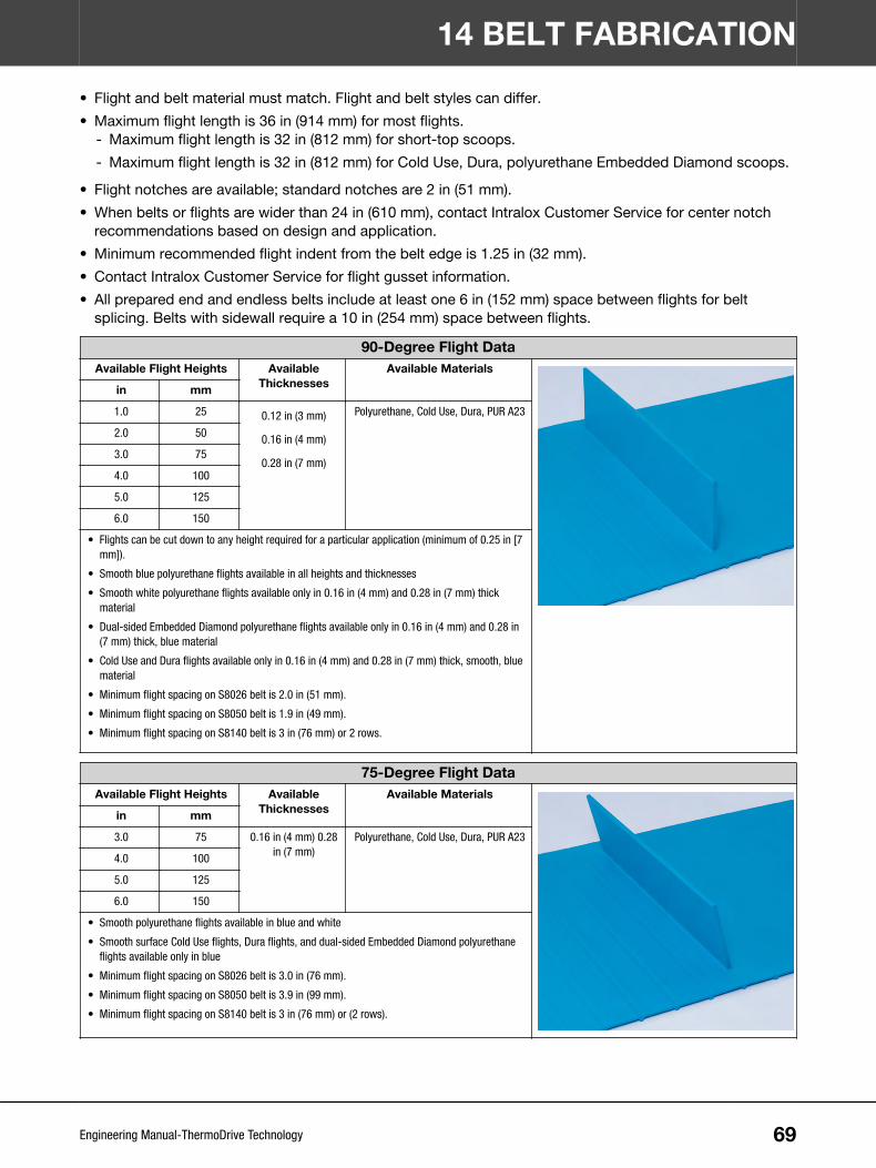
• Flight and belt material must match. Flight and belt styles can differ.
• Maximum flight length is 36 in (914 mm) for most flights.- Maximum flight length is 32 in (812 mm) for short-top scoops.
- Maximum flight length is 32 in (812 mm) for Cold Use, Dura, polyurethane Embedded Diamond scoops.
• Flight notches are available; standard notches are 2 in (51 mm).
• When belts or flights are wider than 24 in (610 mm), contact Intralox Customer Service for center notchrecommendations based on design and application.
• Minimum recommended flight indent from the belt edge is 1.25 in (32 mm).
• Contact Intralox Customer Service for flight gusset information.
• All prepared end and endless belts include at least one 6 in (152 mm) space between flights for beltsplicing. Belts with sidewall require a 10 in (254 mm) space between flights.
90-Degree Flight DataAvailable Flight Heights Available
ThicknessesAvailable Materials
in mm
1.0 25 0.12 in (3 mm)
0.16 in (4 mm)
0.28 in (7 mm)
Polyurethane, Cold Use, Dura, PUR A23
2.0 50
3.0 75
4.0 100
5.0 125
6.0 150
• Flights can be cut down to any height required for a particular application (minimum of 0.25 in [7mm]).
• Smooth blue polyurethane flights available in all heights and thicknesses
• Smooth white polyurethane flights available only in 0.16 in (4 mm) and 0.28 in (7 mm) thickmaterial
• Dual-sided Embedded Diamond polyurethane flights available only in 0.16 in (4 mm) and 0.28 in(7 mm) thick, blue material
• Cold Use and Dura flights available only in 0.16 in (4 mm) and 0.28 in (7 mm) thick, smooth, bluematerial
• Minimum flight spacing on S8026 belt is 2.0 in (51 mm).
• Minimum flight spacing on S8050 belt is 1.9 in (49 mm).
• Minimum flight spacing on S8140 belt is 3 in (76 mm) or 2 rows.
75-Degree Flight DataAvailable Flight Heights Available
ThicknessesAvailable Materials
in mm
3.0 75 0.16 in (4 mm) 0.28in (7 mm)
Polyurethane, Cold Use, Dura, PUR A23
4.0 100
5.0 125
6.0 150
• Smooth polyurethane flights available in blue and white
• Smooth surface Cold Use flights, Dura flights, and dual-sided Embedded Diamond polyurethaneflights available only in blue
• Minimum flight spacing on S8026 belt is 3.0 in (76 mm).
• Minimum flight spacing on S8050 belt is 3.9 in (99 mm).
• Minimum flight spacing on S8140 belt is 3 in (76 mm) or (2 rows).
14 BELT FABRICATION
69Engineering Manual-ThermoDrive Technology

Scoop Flight DataAvailable Flight Heights Available
ThicknessesAvailable Materials
in mm
3.0 75 0.16 in (4 mm), 0.28in (7 mm)
Polyurethane, Cold Use, Dura, PUR A23
4.0 100
5.0 125
6.0 150
• Smooth surface polyurethane flights available in blue and white
• Smooth surface Cold Use flights, Dura flights, and dual-sided Embedded Diamond polyurethaneflights available only in blue
• Scoop angle is 95–105°.
• Minimum flight spacing on S8026 belt is 3.0 in (76 mm).
• Minimum flight spacing on S8050 belt is 3.9 in (99 mm).
• Minimum flight spacing on S8140 belt is 3 in (76 mm) or (2 rows).
Short-Top Scoop Flight DataAvailable Flight Heights Available
ThicknessesAvailable Materials
in mm
3.0 75 0.16 in (4 mm), 0.28in (7 mm)
Polyurethane, Cold Use, Dura, PUR A23
4.0 100
5.0 125
6.0 150
• Smooth surface polyurethane flights available in blue and white
• Smooth surface Cold Use flights, Dura flights, and dual-sided Embedded Diamond polyurethaneflights available only in blue
• Short top scoop angle is 115–125°.
• Minimum flight spacing on S8026 belt is 3.0 in (76 mm).
• Minimum flight spacing on S8050 belt is 3.9 in (99 mm).
• Minimum flight spacing on S8140 belt is 3 in (76 mm) or (2 rows).
FLIGHT GUSSETS CONSIDERATIONSConsider the following when selecting flight gussets.
• Flight gussets increase flight rigidity and are used in heavily loaded applications.
• Contact Intralox Customer Service for application-specific information.
Flight Gusset DataAvailable Gusset Height/
WidthAvailable
ThicknessesAvailable Materials
Height and width based on flightheight
0.28 in (7 mm) Polyurethane, Dura
• Available only on S8050 belts
• Available only for flights 7.0 in (178 mm) or wider
• Flight gusset quantity and spacing are based on flight width
14 BELT FABRICATION
70Engineering Manual-ThermoDrive Technology
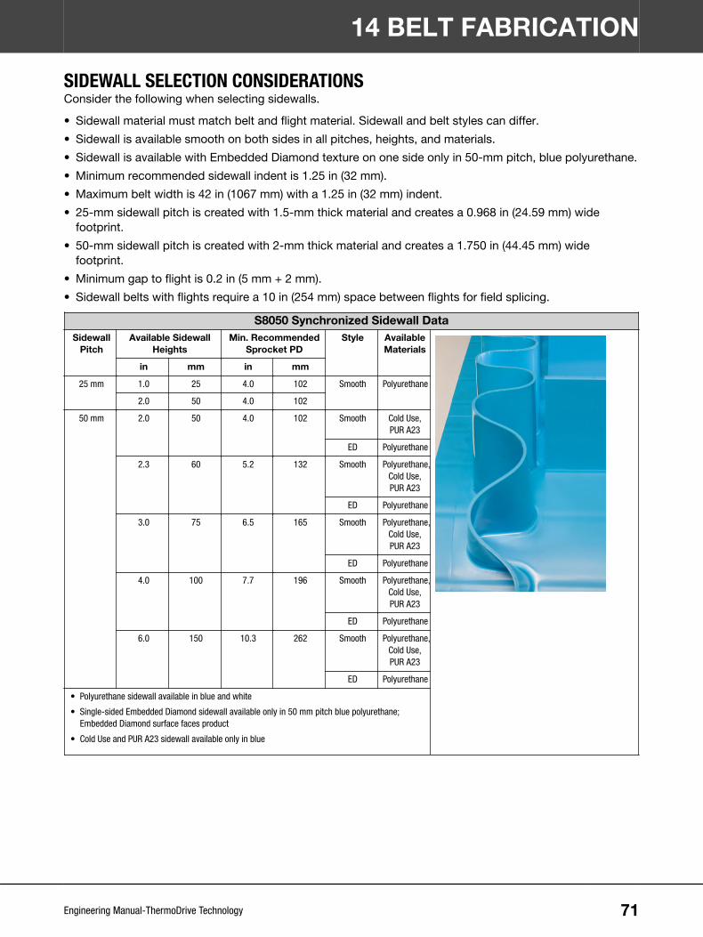
SIDEWALL SELECTION CONSIDERATIONSConsider the following when selecting sidewalls.
• Sidewall material must match belt and flight material. Sidewall and belt styles can differ.
• Sidewall is available smooth on both sides in all pitches, heights, and materials.
• Sidewall is available with Embedded Diamond texture on one side only in 50-mm pitch, blue polyurethane.
• Minimum recommended sidewall indent is 1.25 in (32 mm).
• Maximum belt width is 42 in (1067 mm) with a 1.25 in (32 mm) indent.
• 25-mm sidewall pitch is created with 1.5-mm thick material and creates a 0.968 in (24.59 mm) widefootprint.
• 50-mm sidewall pitch is created with 2-mm thick material and creates a 1.750 in (44.45 mm) widefootprint.
• Minimum gap to flight is 0.2 in (5 mm + 2 mm).
• Sidewall belts with flights require a 10 in (254 mm) space between flights for field splicing.
S8050 Synchronized Sidewall DataSidewall
PitchAvailable Sidewall
HeightsMin. Recommended
Sprocket PDStyle Available
Materials
in mm in mm
25 mm 1.0 25 4.0 102 Smooth Polyurethane
2.0 50 4.0 102
50 mm 2.0 50 4.0 102 Smooth Cold Use,PUR A23
ED Polyurethane
2.3 60 5.2 132 Smooth Polyurethane,Cold Use,PUR A23
ED Polyurethane
3.0 75 6.5 165 Smooth Polyurethane,Cold Use,PUR A23
ED Polyurethane
4.0 100 7.7 196 Smooth Polyurethane,Cold Use,PUR A23
ED Polyurethane
6.0 150 10.3 262 Smooth Polyurethane,Cold Use,PUR A23
ED Polyurethane
• Polyurethane sidewall available in blue and white
• Single-sided Embedded Diamond sidewall available only in 50 mm pitch blue polyurethane;Embedded Diamond surface faces product
• Cold Use and PUR A23 sidewall available only in blue
14 BELT FABRICATION
71Engineering Manual-ThermoDrive Technology

S8140 Synchronized Sidewall DataSidewall
PitchAvailable Sidewall
HeightsMin. Recommended
Sprocket PDStyle Available
Materials
in mm in Teeth
40 mm 2 50 4.0 8 Smooth PUR A23
2.3 60 4.0 8
3 75 5.0 10
4 100 6.0 12
6 150 9.0 18
PUR A23 sidewall available only in blue
V-GUIDE SELECTION CONSIDERATIONSConsider the following when selecting V-Guide.
• V-Guide is only available with S8140 belting.
• V-Guide is available with both prepared end and endless belts.
• There is no minimum V-Guide indent from the edge of the belt and can be installed directly on the sideedges.
• The minimum gap between the V-Guide and any other belt feature (sidewall, flights, or other V-Guide) is0.512 in (13 mm).
• All indents are measured from the outer edge of the V-Guide.
• Maximum belt width is 36 in (914.4 mm).
• Minimum sidewall indent with two lanes of V-Guide on one side of the belt is 2.125 in (54 mm) from theedge of the belt.
• Minimum belt length for S8140 endless belts with V-Guide, sidewall, or flights is 80 drive lugs or 10.37 ft(3.16 m).
• Belts can be purchased with:- One lane of V-Guide on both sides with a 5 in (127 mm) minimum belt width
- One lane of V-Guide on one side with a 5 in (127 mm) minimum belt width
- Two lanes of V-Guide on both sides with a 7 in (178 mm) minimum belt width
14 BELT FABRICATION
72Engineering Manual-ThermoDrive Technology

Polyurethane A23 K13 V-Guide DataV-Guide
SizeDimensions Min. Recommended
SprocketStyle Available
Materials
in (BxHxT) mm(BxHxT)
in mm
K13 0.512 x0.315 x0.276
13 x 8 x 7 4.0 102 Solid PUR A23
PUR A23 V-Guide available in blue
14 BELT FABRICATION
73Engineering Manual-ThermoDrive Technology

15 DRIVE AND IDLE END COMPONENTSDRIVE END SELECTION CONSIDERATIONS• Choose between using a pre-engineered drive solution like the patented Intralox Drive Unit or designing a
drive end solution from individual drive end components.
• Use belt pitch and other conveyor design dimensions to make drive end component decisions. SeeDimensions.
A
C
B
Figure 47: Drive end dimensions
INTRALOX DRIVE UNIT FOR S8050The Intralox Drive Unit is a patented, pre-engineered belt drive subassembly that optimizes ThermoDriveoperational performance. The unit is adaptable to any end drive conveyor design. It bolts directly to theconveyor frame with a standard or custom bolt pattern.
Contact Intralox Customer Service for an Audit Form with details about all available drive unit options.
• Available for new or existing conveyors
• Minimizes harborage
• Simplifies the sanitation process
• Delivers precise and consistent scraping performance
Figure 48: Intralox Drive Unit
Frame: Three-sided, 316 stainless steel construction with smart bar bushings and drive shaft bearings
Drive component choices:
• Full-width sprocket with stainless steel round shaft
• Stacked 6.5 in (165 mm) 10T EZ Clean acetal sprockets on stainless steel square shaft
• Spaced 6.5 in (165 mm) 10T EZ Clean acetal sprockets on stainless steel square shaft
74Engineering Manual-ThermoDrive Technology

Smart bar assembly: Stainless steel smart bar with patented tool-free position limiters with UHMW-PE belt-contact surfaces; choice of bolts or handles for retention
Self-adjusting scraper: Optional, 316 stainless steel assembly with removable UHMW-PE scraper andacetal mounts that attach to the smart bar
Belt compatibility:
• S8050 Flat Top Polyurethane, Cold Use, High Temperature Heavy Load, Dura, or XT belt
• Endless or prepared end belts 5.00–39.25 in (127–1000 mm) wide with or without flights
• Not compatible with sidewall or V-Guide
Spares: Replacement sprockets, position limiters, scrapers, and handles are available for individualpurchase; see the Intralox Drive Unit User Manual on www.intralox.com for a detailed list.
SHAFTSSelect round or square shafts as needed for drive, idle, and returnway component installation. Intralox offerscustomized square shafts. Round shafts are not available from Intralox.
SQUARE SHAFT CONSIDERATIONS• Use only stainless steel shafts for ThermoDrive belt systems.
• ThermoDrive sprockets are only available with 1.5 in, 40 mm, 2.0 in, and 2.5 in bore diameters.
• Retainer ring grooves are not required with sprocket spacers, heavy-duty split retainer rings, or self-setretainer rings.
Contact Intralox Customer Service for a Shaft Specification Form or help with ordering.
CUSTOM SHAFT MACHININGOnce ordered to customer specifications, the shaft stock is cut to length and the raw shaft is precisionstraightened. The bearing journals are turned, and any needed retainer ring grooves, keyways, and chamfersare cut. A thorough quality inspection is performed before shipping.
Notify Intralox Customer Service when ordering if the gearbox is hollow.
Figure 49: Shaft components
A Overall lengthB Bearing-end journalC Square section lengthD Drive-end journal and keyway lengthE Bearing journal diameterF Drive-end journal diameterG Retainer ring groove widthH Sprocket hub widthI Ring groove diameterJ Keyway length
Shafts Available from Intralox U.S. Tolerancesa
Square Size Stainless Steel (303/304) Stainless Steel (316)1.5 in +0.000/-0.006 +0.000/-0.006
2.5 in +0.000/-0.008 +0.000/-0.008
a Contact Intralox Customer Service for larger diameters or shafts longer than 12 ft (3.6 m).
15 DRIVE AND IDLE END COMPONENTS
75Engineering Manual-ThermoDrive Technology

Shafts Available from Intralox Europe Tolerancesa
Square Size Stainless Steel (303/304) Stainless Steel (316)40 mm +0.000/-0.160 N/A
a Contact Intralox Customer Service for larger diameters or shafts longer than 3 m (9.8 ft).
Tolerancesa
Overall Length Journal Diameter Keyway Widths< 48 ± 0.061 in (< 1200 ± 0.8 mm) - 0.0005–0.003 in. (-0.0127–0.0762 mm) + 0.003 in./- 0.000 in. (+ 0.08 mm/- 0.00
mm)> 48 ± 0.0125 in. (< 1200 ± 1.2 mm) (øh7 vlgs. NEN-ISO 286-2)
a U.S. keyways are for parallel square keys (ANSI B17.1 - 1967, R1973). Metric keyways are for flat, inlaid keys with round ends (DIN 6885-A).
Surface FinishesJournal Other Machined Surfaces
63 microinches (1.6 micrometers) 125 microinches (3.25 micrometers)
Shaft Retainer Ring Groove and Chamfer DimensionsShaft Size Groove Diameter Width Chamfer
1.5 in 1.913 ± 0.005 in 0.086 + 0.004/- 0.000 in 2.022 ± 0.010 in
2.5 in 3.287 ± 0.005 in 0.120 + 0.004/- 0.000 in 3.436 ± 0.010 in
40 mm 51 ± 0.1 mm 2.5 + 0.15/- 0.00 mm 54 ± 0.25 mm
RETAINING COMPONENTSSELECTION CONSIDERATIONSRetaining components are available for various shaft sizes, belt loads, and hygienic needs.
• In heavily loaded applications, consider an Intralox Drive Unit with a full-width sprocket or stackedsprockets.
• For stacked sprockets, lock the outermost sprockets in place with heavy-duty retainer rings.
• For spaced sprockets, consider the following options:- Sprocket spacers for hygiene-sensitive applications
- Stainless steel round retainer rings for lighter loads; choose shaft groove location based on sprockethub width and spacing
- Stainless steel self-set retainer rings for lighter loads
- Heavy-duty split retainer rings for heavier loads
Contact Intralox Customer Service for retainer recommendations.
SPROCKET SPACERSSprocket spacers are compatible with the most common spaced sprocket and support wheel applications.They are not for use with drive units, S8126 belts, or component centerline spacing over 3 in (76 mm).
Contact Intralox Customer Service with the following information to calculate the quantity of spacers andheavy-duty split retainer rings for your application. Installation instructions are provided with purchase.
• Belt series and width
• Flights/sidewall needed
• Belt joining method
• Sprocket/wheel choice
• Shaft diameter
15 DRIVE AND IDLE END COMPONENTS
76Engineering Manual-ThermoDrive Technology

• Scraper needed
X-Ray Detectable Sprocket Spacer DataNom.
SprocketSpacerWidth in
Nom.SprocketSpacer
Width mm
Available Bore Sizes
U.S. Sizes Metric Sizes
Round in Square in Round mm Square mm
1.0 25 1.5 40
1.5 38 1.5 40
2.0 51 1.5 40
Detectable Sprocket Spacer DataNom.
SprocketSpacerWidth in
Nom.SprocketSpacer
Width mm
Available Bore Sizes
U.S. Sizes Metric Sizes
Round in Square in Round mm Square mm
1.0 25 1.5 40
1.5 38 1.5 40
2.0 51 1.5 40
STAINLESS STEEL RETAINER RINGSStainless steel retainer rings are available from Intralox to fit Intralox square shafts.
• The ring is ANSI Type 3AMI ring, conforming to MIL SPEC R-2124B.
• The ring requires shaft grooves and chamfers.
• Fasteners are included to join ring ends.
• See the related shaft groove and chamfer information in Drive Shaft.
A
A Ring groove diameterFigure 50: Retainer ring groove diameter
STAINLESS STEEL SELF-SET RETAINER RING• Self-set retainer rings are available to fit 1.5 in, 2.5 in, 40 mm, and other square shafts. Shafts must have
chamfered edges. Machined grooves are not needed.
• These retainer rings are made from non-corrosive 316 stainless steel. They are USDA accepted andpatented.
• The retainer rings snap into place on the square shaft even with the shaft installed. Retainer rings are fixedin position with a unique setscrew that does not fall out during operation.
• These retainer rings are not recommended in applications where high lateral forces are expected.
15 DRIVE AND IDLE END COMPONENTS
77Engineering Manual-ThermoDrive Technology

A
A Custom setscrew fully inserted head firstFigure 51: Self-set retainer ring
STAINLESS STEEL HEAVY-DUTY SPLIT RETAINER RING• Heavy-duty split retainer rings are available to fit 1.5 in, 2.5 in, and 40-mm square shafts.
• The retainer rings are made from 304 stainless steel.
• These retainer rings do not require the shaft to be chamfered, and can be installed with the shaft in place.
• These retainer rings can be used in applications with high lateral loads on the sprockets.
Figure 52: Heavy-duty split retainer ring
15 DRIVE AND IDLE END COMPONENTS
78Engineering Manual-ThermoDrive Technology
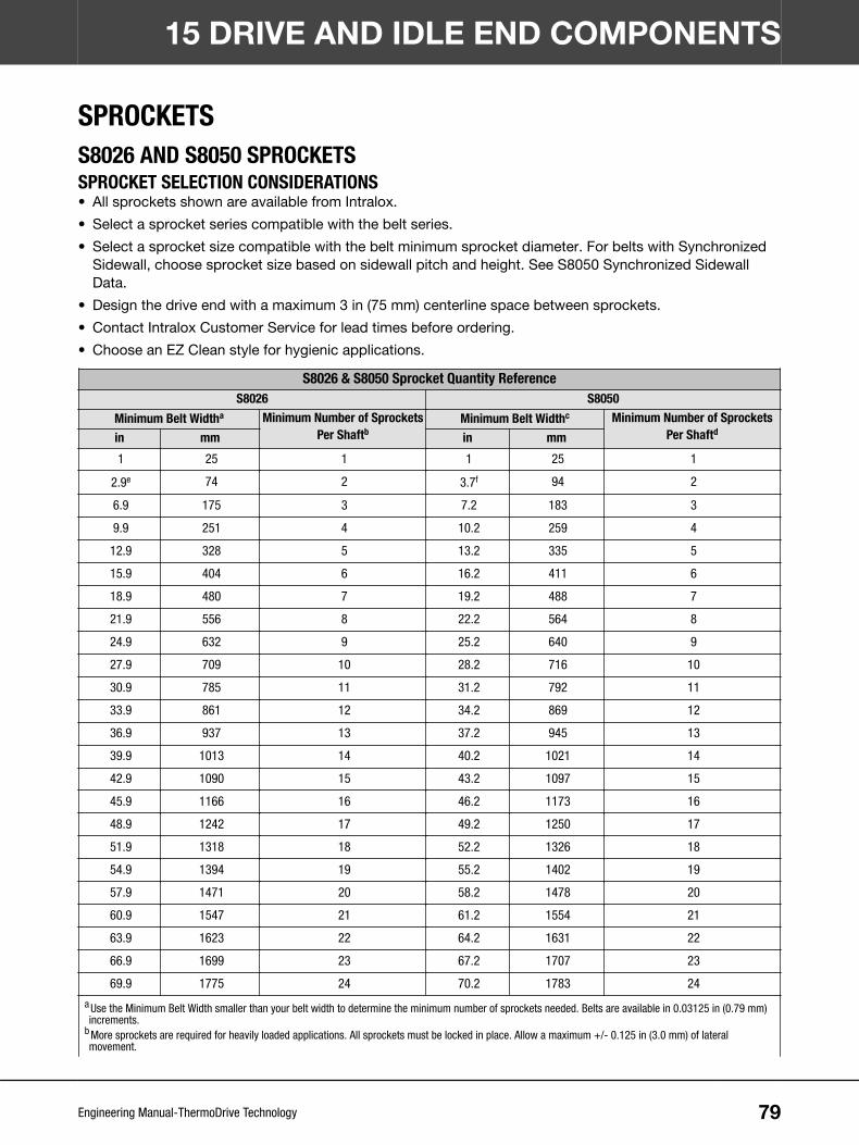
SPROCKETSS8026 AND S8050 SPROCKETSSPROCKET SELECTION CONSIDERATIONS• All sprockets shown are available from Intralox.
• Select a sprocket series compatible with the belt series.
• Select a sprocket size compatible with the belt minimum sprocket diameter. For belts with SynchronizedSidewall, choose sprocket size based on sidewall pitch and height. See S8050 Synchronized SidewallData.
• Design the drive end with a maximum 3 in (75 mm) centerline space between sprockets.
• Contact Intralox Customer Service for lead times before ordering.
• Choose an EZ Clean style for hygienic applications.
S8026 & S8050 Sprocket Quantity ReferenceS8026 S8050
Minimum Belt Widtha Minimum Number of SprocketsPer Shaftb
Minimum Belt Widthc Minimum Number of SprocketsPer Shaftdin mm in mm
1 25 1 1 25 1
2.9e 74 2 3.7f 94 2
6.9 175 3 7.2 183 3
9.9 251 4 10.2 259 4
12.9 328 5 13.2 335 5
15.9 404 6 16.2 411 6
18.9 480 7 19.2 488 7
21.9 556 8 22.2 564 8
24.9 632 9 25.2 640 9
27.9 709 10 28.2 716 10
30.9 785 11 31.2 792 11
33.9 861 12 34.2 869 12
36.9 937 13 37.2 945 13
39.9 1013 14 40.2 1021 14
42.9 1090 15 43.2 1097 15
45.9 1166 16 46.2 1173 16
48.9 1242 17 49.2 1250 17
51.9 1318 18 52.2 1326 18
54.9 1394 19 55.2 1402 19
57.9 1471 20 58.2 1478 20
60.9 1547 21 61.2 1554 21
63.9 1623 22 64.2 1631 22
66.9 1699 23 67.2 1707 23
69.9 1775 24 70.2 1783 24
a Use the Minimum Belt Width smaller than your belt width to determine the minimum number of sprockets needed. Belts are available in 0.03125 in (0.79 mm)increments.
b More sprockets are required for heavily loaded applications. All sprockets must be locked in place. Allow a maximum +/- 0.125 in (3.0 mm) of lateralmovement.
15 DRIVE AND IDLE END COMPONENTS
79Engineering Manual-ThermoDrive Technology

S8026 & S8050 Sprocket Quantity ReferenceS8026 S8050
Minimum Belt Widtha Minimum Number of SprocketsPer Shaftb
Minimum Belt Widthc Minimum Number of SprocketsPer Shaftdin mm in mm
c Use the Minimum Belt Width smaller than your belt width to determine the minimum number of sprockets needed. Belts are available in 0.03125 in (0.79 mm)increments.
d More sprockets are required for heavily loaded applications. All sprockets must be locked in place. Allow a maximum +/- 0.125 in (3.0 mm) of lateralmovement.
e For S8026 belt widths 2.875–4.375 in (73–111 mm), stack sprockets between heavy-duty split retainer rings.f For S8050 belt widths 3.6875–4.6875 (94–119 mm), stack sprockets between heavy-duty split retainer rings.
Sprocket Spacing as a Function of Belt Strength Used
A B
PERCENT OF ALLOWABLE BELT STRENGTH USED, %A:MAXIMUM SPROCKET SPACING, inB:MAXIMUM SPROCKET SPACING, mm
• Based on maximum centerline sprocket spacing of 3 in (76 mm)
• Applies to all ThermoDrive series and styles
• For applications that exceed the rated belt pull by over 50%, contact Intralox Customer Service.
S8026 EZ Clean Molded Acetal Sprocket Data
No. ofTeeth
Nom.PitchDia. in
Nom.PitchDia.mm
Nom.OuterDia. in
Nom.OuterDia.mm
Nom.Hub
Widthin
Nom.Hub
Widthmm
Available Bore Sizes
U.S. Sizes Metric Sizes
Roundin
Squarein
Roundmm
Squaremm
6a 2.0 51 1.9 48 1.0 25 1 25
10 3.2 81 3.2 81 1.0 25 1 25
1.5 40
12 3.9 99 3.8 97 1.0 25 1.5 40
20 6.4 163 6.4 162 1.0 25 1.5 40
a Not compatible with ThermoLace
15 DRIVE AND IDLE END COMPONENTS
80Engineering Manual-ThermoDrive Technology

S8026 EZ Clean Machined Acetal Sprocket Data
No. ofTeeth
Nom.PitchDia. in
Nom.PitchDia.mm
Nom.OuterDia. in
Nom.OuterDia.mm
Nom.Hub
Widthin
Nom.Hub
Widthmm
Available Bore Sizes
U.S. Sizes Metric Sizes
Roundin
Squarein
Roundmm
Squaremm
8a 2.5 64 2.5 64 1.0 25 1 25
a Not compatible with ThermoLace
S8026 EZ Clean No-Lace Machined Acetal Sprocket Data
No. ofTeeth
Nom.PitchDia. in
Nom.PitchDia.mm
Nom.OuterDia. in
Nom.OuterDia.mm
Nom.Hub
Widthin
Nom.Hub
Widthmm
Available Bore Sizes
U.S. Sizes Metric Sizes
Roundin
Squarein
Roundmm
Squaremm
20 6.4 163 6.4 162 1 25 1.5 40
S8050 EZ Clean Molded Acetal Sprocket Data
No. ofTeeth
Nom.PitchDia. in
Nom.PitchDia.mm
Nom.OuterDia. in
Nom.OuterDia.mm
Nom.Hub
Widthin
Nom.Hub
Widthmm
Available Bore Sizes
U.S. Sizes Metric Sizes
Roundin
Squarein
Roundmm
Squaremm
6 4.0 102 3.7 94 1.5 38 1.5 40
8 5.2 132 5.0 127 1.5 38 1.5 40
10 6.5 165 6.3 160 1.5 38 1.5 40
12 7.7 196 7.6 193 1.5 38 1.5 40
S8050 EZ Clean Machined Acetal Sprocket Data
No. ofTeeth
Nom.PitchDia. in
Nom.PitchDia.mm
Nom.OuterDia. in
Nom.OuterDia.mm
Nom.Hub
Widthin
Nom.Hub
Widthmm
Available Bore Sizes
U.S. Sizes Metric Sizes
Roundin
Squarein
Roundmm
Squaremm
10 6.5 165 6.3 160 1.0 25 2.0
2.5
12 7.7 196 7.6 193 1.0 25 2.0
2.5
16a 10.3 262 10.1 255 1.0 25 1.5 40
2.5
a Not compatible with ThermoLace
15 DRIVE AND IDLE END COMPONENTS
81Engineering Manual-ThermoDrive Technology
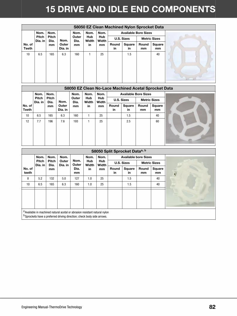
S8050 EZ Clean Machined Nylon Sprocket Data
No. ofTeeth
Nom.PitchDia. in
Nom.PitchDia.mm
Nom.OuterDia. in
Nom.OuterDia.mm
Nom.Hub
Widthin
Nom.Hub
Widthmm
Available Bore Sizes
U.S. Sizes Metric Sizes
Roundin
Squarein
Roundmm
Squaremm
10 6.5 165 6.3 160 1 25 1.5 40
S8050 EZ Clean No-Lace Machined Acetal Sprocket Data
No. ofTeeth
Nom.PitchDia. in
Nom.PitchDia.mm
Nom.OuterDia. in
Nom.OuterDia.mm
Nom.Hub
Widthin
Nom.Hub
Widthmm
Available Bore Sizes
U.S. Sizes Metric Sizes
Roundin
Squarein
Roundmm
Squaremm
10 6.5 165 6.3 160 1 25 1.5 40
12 7.7 196 7.6 193 1 25 2.5 60
S8050 Split Sprocket Dataa, b
No. ofteeth
Nom.PitchDia. in
Nom.PitchDia.mm
Nom.OuterDia. in
Nom.OuterDia.mm
Nom.Hub
Widthin
Nom.Hub
Widthmm
Available bore Sizes
U.S. Sizes Metric Sizes
Roundin
Squarein
Roundmm
Squaremm
8 5.2 132 5.0 127 1.0 25 1.5 40
10 6.5 165 6.3 160 1.0 25 1.5 40
a Available in machined natural acetal or abrasion resistant natural nylonb Sprockets have a preferred driving direction; check body side arrows.
15 DRIVE AND IDLE END COMPONENTS
82Engineering Manual-ThermoDrive Technology

Full Width Sprocketa
Standard WidthsNo. ofTeeth
Nom.PitchDia.
Nom.OuterDia.
DyeOptions
BearingJournal
Dia.
GearboxJournal
Dia.
GearboxJournalLength
A:Bearing Journal
B:Gearbox Journal
C:Gearbox Journal Length
10 in (254 mm) 106.5 in (165
mm)6.3 in (160
mm)Dye or No
DyeUp to 2 in (50
mm)Up to 2 in (50
mm)Up to 15 in(381 mm)
12 in (305 mm)
16 in (406 mm)
18 in (457 mm)
20 in (508 mm)
24 in (610 mm)
30 in (762 mm)
36 in (914 mm)
a Contact Intralox Customer Service for details on widths.
S8126 SPROCKETS AND DRIVE ENDS8126 Drive End Component Quantity Reference Data
Belt Width (in)
2.5 in (65mm) WideFlangedSupportRoller
2.5 in (65mm) WideSupportRoller
1 in (25 mm)Wide Support
Roller
6 in (152mm) WideTail Roller
SS Heavy-duty Split
Retainer Ring
ComponentSpacing Edge
to Edge
Minimum TotalBelt EdgeClearance
MinimumLength of
Square Portionof Shaft
in mm Quantity Quantity Quantity Quantity Quantity in mm in mm in mm10 254 0 2 0 1 2 0 0 0.25 7 12.25 311
11 279 0 2 0 1 6 1 25 0.25 7 14.25 362
12 305 0 2 0 1 6 1 25 0.25 7 14.25 362
13 330 0 2 0 1 6 1 25 0.25 7 14.25 362
14 356 0 2 0 1 6 1.5 38 0.25 7 15.25 387
15 381 0 2 0 1 6 2 51 0.25 7 16.25 413
16 406 0 2 2 1 6 0.75 19 0.25 7 17.25 438
17 432 0 2 2 1 6 1 25 0.25 7 18.25 464
18 457 0 2 2 1 10 1.25 32 0.25 7 19.25 489
19 483 0 2 2 1 10 1.5 38 0.25 7 20.25 514
20 508 0 2 2 1 10 1.75 44 0.25 7 21.25 540
21 533 0 2 2 1 10 2 51 0.25 7 22.25 565
22 559 0 2 2 1 10 2.25 57 0.25 7 23.25 591
23 584 0 4 0 1 10 1.75 44 0.25 7 24.25 616
24 610 0 4 0 1 10 2 51 0.25 7 25.25 641
15 DRIVE AND IDLE END COMPONENTS
83Engineering Manual-ThermoDrive Technology

S8126 Machined Acetal Sprocket Dataa
No. ofTeeth
Nom.PitchDia. in
Nom.PitchDia.mm
Nom.OuterDia. in
Nom.OuterDia.mm
Nom.Hub
Widthin
Nom.Hub
Widthmm
Available Bore Sizes
U.S. Sizes Metric Sizes
Roundin
Squarein
Roundmm
Squaremm
12b 3.9 99 3.9 99 6.0 152 1.5 40
a Contact Intralox Customer Service for lead times.b Not compatible with ThermoLace
S8140 SPROCKETSS8140 Machined Acetal Sprocket Dataa
No. ofTeeth
Nom.PitchDia. in
Nom.PitchDia.mm
Nom.OuterDia. in
Nom.OuterDia.mm
Nom.Hub
Widthin
Nom.Hub
Widthmm
Available Bore Sizes
U.S. Sizes Metric Sizes
Roundin
Squarein
Roundmm
Squaremm
10 5.2 133 5.0 127 8 203 1.5 40
12 6.2 159 6.0 153 8 203 1.5 40
18 9.3 237 9.1 231 8 203 1.5 40
18 9.3 237 9.1 231 8 203 2.5
a Not compatible with ThermoLace
POSITION LIMITERSIntralox provides various wear shoe-style position limiters for installation at the conveyor drive end. All stylesshown are available from Intralox.
• EZ Clean Universal position limiters are most often used on flat and flighted belts.
• EZ Clean D-shaft position limiters are only for flat belts with light loads.
• Available only in UHMW-PE
EZ Clean Position Limiter (Universal Mount) DataNom. Pitch
Dia. inNom. Pitch
Dia. mmDimensions (HxWxD)
in mm
2.0 51
3.27 x 2.31 x 0.75 83 x 59 x192.5 64
3.2 81
3.9 993.54 x 2.82 x 0.75 90 x 72 x 19
4.0 102
5.2 132 3.56 x 3.04 x 0.75 90 x 77 x 19
6.4 1633.68 x 3.29 x 0.75 93 x 84 x 19
6.5 165
7.7 196 3.90 x 3.21 x 0.75 99 x 82 x 19
15 DRIVE AND IDLE END COMPONENTS
84Engineering Manual-ThermoDrive Technology

EZ Clean Position Limiter (D-Shaft Mount) DataNom. Pitch
Dia. inNom. Pitch
Dia. mmDimensions (HxWxD)
in mm
2.0 51
3.46 x 2.31 x 0.75 88 x 59 x 192.5 64
3.2 81
3.9 993.71 x 2.82 x 0.75 94 x 72 x 19
4.0 102
5.2 132 3.75 x 3.04 x 0.75 95 x 77 x 19
6.4 1633.87 x 3.29 x 0.75 98 x 84 x 19
6.5 165
7.7 196 3.71 x 3.15 x 0.75 94 x 80 x 19
S8026 Position Limiter (D-Shaft Mount) Installation DimensionsSprocket PD 5.3 mm Flat Top 6 mm Flat Top 6.3 mm EDT 7.4 mm NT
A B A B A B A B3.2 in (81
mm)3.356 in (85.2
mm)0.200 in (5.1
mm)3.378 in (85.8
mm)0.215 in (5.5
mm)3.388 in (86.1
mm)0.223 in (5.7
mm)3.425 in (87.0
mm)0.248 in (6.3
mm)
3.9 in (99mm)
3.659 in (92.9mm)
0.005 in (0.1mm)
3.681 in (93.5mm)
0.010 in (0.3mm)
3.691 in (93.8mm)
0.015 in (0.4mm)
3.728 in (94.7mm)
0.028 in (0.7mm)
6.4 in (163mm)
4.898 in(124.4 mm)
0.389 in (9.9mm)
4.921 in(125.0 mm)
0.404 in (10.3mm)
4.931 in(125.2 mm)
0.412 in (10.5mm)
4.969 in(126.2 mm)
0.437 in (11.1mm)
S8050 Position Limiter (D-Shaft Mount) Installation DimensionsSprocket PD 7.0 mm Flat Top 7.5 mm EDT 8.0 mm NT
A B A B A B4.0 in (102 mm) 3.662 in
(93.0 mm)0.001 in (0.0
mm)3.684 in
(93.6 mm)0.015 in (0.4
mm)3.706 in
(94.1 mm)0.030 in (0.8
mm)
5.2 in (132 mm) 4.270 in(108.5 mm)
0.215 in (5.5mm)
4.294 in(109.1 mm)
0.219 in (5.6mm)
4.316 in(109.6 mm)
0.221 in (5.6mm)
6.5 in (165 mm) 4.882 in(124.0 mm)
0.392 in(10.0 mm)
4.899 in(124.4 mm)
0.404 in(10.3 mm)
4.916 in(124.9 mm)
0.413 in(10.5 mm)
15 DRIVE AND IDLE END COMPONENTS
85Engineering Manual-ThermoDrive Technology

S8026 Position Limiter (Universal Mount) Installation DimensionsSprocket PD 5.3 mm Flat Top 6.0 mm Flat Top 6.3 mm EDT 7.4 mm NT
C D C D C D C D3.2 in (81
mm)4.166 in
(105.8 mm)0.819 in (20.8
mm)4.188 in
(106.4 mm)0.804 in (20.4
mm)4.199 in
(106.7 mm)0.796 in (20.2
mm)4.236 in
(107.6 mm)0.772 in (19.6
mm)
3.9 in (99mm)
4.469 in(113.5 mm)
0.995 in (25.3mm)
4.491 in(114.1 mm)
0.990 in (25.1mm)
4.502 in(114.4 mm)
0.985 in (25.0mm)
4.539 in(115.3 mm)
0.972 in (24.7mm)
6.4 in (163mm)
5.708 in(145.0 mm)
0.611 in (15.5mm)
5.731 in(145.6 mm)
0.596 in (15.1mm)
5.742 in(145.8 mm)
0.588 in (14.9mm)
5.780 in(146.8 mm)
0.563 in (14.3mm)
S8050 Position Limiter (Universal Mount) Installation DimensionsSprocket PD 7.0 mm Flat Top 7.5 mm EDT 8.0 mm NT
C D C D C D4.0 in (102 mm) 4.472 in (113.6
mm)0.999 in (25.4
mm)4.481 in (113.8
mm)0.995 in (25.3
mm)4.517 in (114.7
mm)0.970 in (24.7
mm)
5.2 in (132 mm) 5.080 in (129.0mm)
0.785 in (19.9mm)
5.087 in (129.2mm)
0.783 in (19.9mm)
5.123 in (130.1mm)
0.779 in (19.8mm)
6.5 in (165 mm) 5.692 in (144.6mm)
0.608 in (15.4mm)
5.699 in (144.8mm)
0.603 in (15.3mm)
5.727in (145.5mm)
0.587 in (14.9mm)
0.625 in (15.88 mm)
00
0.50
0 in
(1
2.70
mm
)
1.50
0 in
(3
8.10
mm
)
C
D
Position Limiter Block DataNom. Pitch
Dia. inNom. Pitch
Dia. mmDimensions (HxWxD)
in mm
2.0 51
3.25 x 2.5 x 1 83 x 64 x 252.5 64
3.2 81
3.9 993.75 x 3 x 1 95 x 76 x 25
4.0 102
5.2 132 4 x 3.25 x 1 102 x 83 x 25
6.4 1634 x 3.5 x 1 102 x 89 x 25
6.5 165
10.3 262 4.5 x 4.2 x 1 114 x 107 x 25
15 DRIVE AND IDLE END COMPONENTS
86Engineering Manual-ThermoDrive Technology

Flighted Belt Position Limiter Kit DataNom. Pitch
Dia. inNom. Pitch
Dia. mmDimensions (HxWxD)a
in mm
2.5 641.5 x 3 x 1 38 x 76 x 25
3.2 81
3.9 992 x 2 x 1 51 x 51 x 25
4.0 102
5.2 132 2.5 x 2 x 1 64 x 51 x 25
6.4 163 3 x 2 x 1 76 x 51 x 25
6.5 165
a Dimensions do not include mounting plate.
SCRAPERSSCRAPER SELECTION CONSIDERATIONS• Plan to use position limiters with any scraper.
• Only the EZ Mount Flex Tip Scraper is available from Intralox. Source alternate scrapers from othervendors based on design guideline criteria. See Belt Scraper.
• Only use the EZ Mount Flex Tip Scraper in wet or greasy applications where the flexible tip materialremains moist.
EZ Mount Flex Tip Scraper DataAvailable Height Available Length
Materialin mm in mm
2.75 70 72 1830 rigid PVC base with flexiblepolyurethane tip
• Available only in one size
• Can be cut to length upon receipt
• Designed for wet or greasy product applications
• Not for use with dry products or applications
• FDA Compliant; does not meet EU regulations for food safety
EZ MOUNT FLEX TIP SCRAPER DATAEZ Mount Flex Tip Scraper Data
Available Height Available LengthMaterial
in mm in mm
2.75 70 72 1830 rigid PVC base with flexiblepolyurethane tip
• Available only in one size
• Can be cut to length upon receipt
• Designed for wet or greasy product applications
• Not for use with dry products or applications
• FDA Compliant; does not meet EU regulations for food safety
15 DRIVE AND IDLE END COMPONENTS
87Engineering Manual-ThermoDrive Technology

SUPPORT WHEELS AND ROLLERSS8026 AND S8050 IDLE END• Support wheels and rollers are compatible with S8026 and S8050 belts unless otherwise indicated.
• Support wheels are designed for use on square shafts. When using round shafts, use return rollers.
• Support wheel and roller diameters must meet the minimum sprocket diameter required for the belt.
• Choose flanged rollers only for shaft outside ends when belt containment is required.
• Contact Intralox Customer Service for lead times.
ThermoDrive Support Wheel Dataa
Nom.WheelDia. in
Nom.Wheel
Dia. mm
Nom. HubWidth in
Nom. HubWidth mm
Available Bore Sizes
U.S. Sizes Metric Sizes
Round in Square in Roundmm
Squaremm
3.9 99 1.0 25 1.5 40
5.2 132 1.0 25 1.5 40
6.5 165 1.0 25 1.5 40
7.7 196 1.0 25 1.5
2.5
10.3 262 1.0 25 1.5
2.5
a Designed to work with corresponding diameter sprockets; material is UHMW-PE.
ThermoDrive Return Roller Dataa
Nom.RollerDia. in
Nom.Roller
Dia. mm
Nom. HubWidth in
Nom. HubWidth mm
Available Bore Sizes
U.S. Sizes Metric Sizes
Round in Square in Roundmm
Squaremm
4.0 102 1.0 25 0.75
4.0 102 1.0 25 1.0
a Material is UHMW-PE.
ThermoDrive Flanged Roller Dataa
Nom.RollerDia. inb
Nom.Roller
Dia. mmc
Nom. HubWidth ind
Nom. HubWidthmme
Available Bore Sizes
U.S. Sizes Metric Sizes
Round in Square in Roundmm
Squaremm
4.0 102 1.0 25 0.75
4.0 102 1.0 25 1.0
a Material is UHMW-PE.b Flange of 0.75 in (19 mm) is not included in nominal roller diameter; actual roller diameter is 5.5 in (140 mm).c Flange of 0.75 in (19 mm) is not included in nominal roller diameter; actual roller diameter is 5.5 in (140 mm).d Flange is not included in nominal hub width; actual hub width is 1.23 in (31 mm).e Flange is not included in nominal hub width; actual hub width is 1.23 in (31 mm).
15 DRIVE AND IDLE END COMPONENTS
88Engineering Manual-ThermoDrive Technology

S8126 IDLE ENDS8126 Idle End Component Quantity Reference Data
Belt Width
2.5 in (65mm) WideFlangedSupportRoller
2.5 in (65mm) WideSupportRoller
1 in (25 mm)Wide Support
Roller
6 in (152mm) WideTail Roller
SS Heavy-dutySplit Retainer
Ring
ComponentSpacing Edge
to Edge
Minimum TotalBelt EdgeClearance
MinimumLength of
Square Portionof Shaft
in mm Quantity Quantity Quantity Quantity Quantity in mm in mm in mm10 254 2 0 0 1 2 0 0 0.25 7 11.25 286
11 279 2 0 0 1 6 1 25 0.25 7 13.25 337
12 305 2 0 0 1 6 1 25 0.25 7 13.25 377
13 330 2 0 0 1 6 1.5 38 0.25 7 14.25 362
14 356 2 0 0 1 6 2 51 0.25 7 15.25 387
15 381 2 0 0 1 6 2.5 64 0.25 7 16.25 413
16 406 2 0 2 1 6 1 25 0.25 7 17.25 438
17 432 2 0 2 1 10 1.25 32 0.25 7 18.25 718
18 457 2 0 2 1 10 1.5 38 0.25 7 19.25 489
19 483 2 0 2 1 10 1.75 44 0.25 7 20.25 514
20 508 2 0 2 1 10 2 51 0.25 7 21.25 540
21 533 2 0 2 1 10 2.25 57 0.25 7 22.25 565
22 559 2 0 2 1 10 2.5 64 0.25 7 23.25 591
23 584 2 2 0 1 10 2 51 0.25 7 24.25 616
24 610 2 2 0 1 10 2.25 57 0.25 7 25.25 641
S8126 Acetal Support Wheel Dataa
Nom.RollerDia. in
Nom.Roller
Dia. mm
Nom. HubWidth in
Nom. HubWidth mm
Available Bore Sizes
U.S. Sizes Metric Sizes
Roundin
Square in Roundmm
Squaremm
4.0 102 1.0 25 1.5 40
4.0 102 2.5 64 1.5 40
a Contact Intralox Customer Service for lead times.
S8126 Acetal Flanged Roller Dataa
Nom.RollerDia. in
Nom.Roller
Dia. mm
Nom. HubWidth in
Nom. HubWidth mm
Available Bore Sizes
U.S. Sizes Metric Sizes
Roundin
Square in Roundmm
Squaremm
4.0 102 2.5 64 1.5 40
a Contact Intralox Customer Service for lead times.
15 DRIVE AND IDLE END COMPONENTS
89Engineering Manual-ThermoDrive Technology

S8126 Acetal Tail Roller Dataa
Nom.RollerDia. in
Nom.Roller
Dia. mm
Nom. HubWidth in
Nom. HubWidth mm
Available Bore Sizes
U.S. Sizes Metric Sizes
Roundin
Square in Roundmm
Squaremm
4.0 102 6.0 152 1.5 40
a Contact Intralox Customer Service for lead times.
S8140 IDLE END• Support wheels and rollers are compatible with S8140 belts only.
• Support wheels are designed for use on square shafts. When using round shafts, use return rollers.
• Support wheel and roller diameters must meet the minimum sprocket diameter required for the belt.
• Choose flanged rollers only for shaft outside ends when belt containment is required.
• Contact Intralox Customer Service for lead times.
S8140 Acetal Support Wheel DataNom.RollerDia. in
Nom.Roller
Dia. mm
Nom. HubWidth in
Nom. HubWidth mm
Available Bore Sizes
U.S. Sizes Metric Sizes
Roundin
Square in Roundmm
Squaremm
5.0 127 2.0 51 1.5 40
5.0 127 4.0 102 1.5 40
6.0 153 2.0 51 1.5 40
6.0 153 4.0 102 1.5 40
9.1 231 2.0 51 1.5 40
9.1 231 4.0 102 2.5
S8140 Acetal Tail Roller DataNom.RollerDia. in
Nom.Roller
Dia. mm
Nom. HubWidth in
Nom. HubWidth mm
Available Bore Sizes
U.S. Sizes Metric Sizes
Roundin
Square in Roundmm
Squaremm
5.0 127 8.0 203 1.5 40
6.0 153 8.0 203 1.5 40
9.1 231 8.0 203 1.5 40
9.1 231 8.0 203 2.5
15 DRIVE AND IDLE END COMPONENTS
90Engineering Manual-ThermoDrive Technology

16 CARRYWAY AND RETURNWAYCOMPONENTSSUPPORT RAILS/WEARSTRIPSSTANDARD FLAT WEARSTRIPS• Standard flat wearstrips are available in UHMW-PE measuring 0.25 in (6 mm) thick x 1.25 in (32 mm) wide
x 120 in (3 m).
• UHMW-PE wearstrips are FDA and USDA compliant for direct food contact.
1.25 ± 0.030 in (31.75 ± 0.76 mm)
0.250 in(6.35 mm)
0.25 in X 1.25 in X 120 in Long Flat UHMW Wearstrip (B6XX31IXXWMV)
NOTE: Recommended for installation with S8126 belting.
SPECIALTY WEARSTRIPSIntralox offers various clip-on wearstrips including the following:
• For new applications, use flat wearstrips with wide surface area for carryways and returnways.
• Use clip-on wearstrips only for lightly loaded retrofit applications or to prove concepts. They are notrecommended for normal production operation.
• Contact Intralox Customer Service for application-specific information.
A
3/32 in(2 mm)
2 in(51 mm) 0.5 in
(13 mm)
7/64 in R(3 mm)
1.5 in(38 mm) 0.25 in
(6 mm)
0.125 in(3 mm)
19/32 in(15 mm)
1.75 in(44 mm)
1.5 in(38 mm)
B
120 in (3.0 m) guide rail Snap-On UHMW wearstrips (B6XX27IXXWMV) 120 in (3.0 m) Barbed Clip-On UHMW wearstrips (B6XX23IXXWMV)
STAINLESS STEEL-BACKED UHMW-PE WEARSTRIP COMPONENTS• For new applications, use flat wearstrips with a wide surface area for carryways and returnways.
• Only use stainless steel-backed UHMW-PE wearstrips for lightly loaded retrofit applications or to proveconcepts.
• Stainless steel-backed UHMW-PE wearstrips can create a rigid belt carryway surface on any frame withcross members.
• Stainless steel-backed UHMW-PE wearstrips should be mounted to cross members with a self-tighteningstainless steel clamp with nut (sold separately).
• Wearstrips can be installed in parallel, chevron, or other configurations.
• Ensure installation design allows for thermal expansion and contraction.
• Chamfer or bend down the leading edges of any wearstrip.
• Recommended for temperatures up to 160°F (71°C)
NOTE: Recommended for Trough Retrofit Set installations.
91Engineering Manual-ThermoDrive Technology

0.84 in(21.3 mm)
1.25 in(31.8 mm)
0.75 in(19.05 mm)
0.18 in(4.572 mm)
"T" 120 in (3.05 m) Stainless Steel Back UHMWWearstrip (B6XX42IXXWMV)
Self-tightening Stainless Steel Wearstrip clamp withnut 5/16-18 UNC (C9AX1XXXXXXX)
6 in (152 mm) Stainless Steel Connector for StainlessSteel Back Wearstrip (C4BXXXXXXXMT)
SHAFTSSelect round or square shafts as needed for carryway and returnway component installation.
• Intralox offers customized square shafts. See Square Shaft Considerations.
• Round shafts are not available from Intralox.
RETURN ROLLERSSee Support Wheels and Rollers.
TROUGH CONVERTERThe ThermoDrive Trough Converter is designed to provide components to quickly and simply upgrade anexisting tensioned, flat belt, troughed conveyor for use with tensionless ThermoDrive technology. The troughconverter is also used for new conveyor installation.
• The frame has a center-mounted carryway support that is round or square (at a 45-degree angle).
• The application is compatible with a curved trough shape.
• Belts can be any style of S8026 or S8050 (compatible with full-length drive bars, trough grooves, or drivebar removal); with a minimum width of 10 in (254 mm) and a maximum of 42 in (1067 mm); belts can bespliced.
• The trough converter is not compatible with ThermoLace or metal lace belts.
Figure 53: Trough converter
Components:
• Bracket set includes stainless steel flat, transition, and trough brackets
• 120 in (3048 mm) 304/304L stainless steel rod with 0.625 in (16 mm) diameter to reinforce bracket rigidity
16 CARRYWAY AND RETURNWAYCOMPONENTS
92Engineering Manual-ThermoDrive Technology

• 120 in (3048 mm) UHMW-PE T-shape wearstrips with 1.54 in (39 mm) height and 1.3 in (33 mm) contactsurface width
• Wearstrip notching kit
Troughed conveyors must meet specifications in the ThermoDrive Trough Converter Audit Form. InstallationInstructions can be found at www.intralox.com.
Figure 54: Trough converter components
A Trough bracketB Transition bracketC WearstripD Wearstrip notching kitE Flat bracketF Steel rod
16 CARRYWAY AND RETURNWAYCOMPONENTS
93Engineering Manual-ThermoDrive Technology

17 SPLICING EQUIPMENTTHERMODRIVE SPLICING SYSTEM V2This patented belt splicing solution provides tools to prepare belt ends and efficiently splice them in the field.The splicer is compatible with Intralox ThermoDrive conveyor belt series and styles up to 42 in (1067 mm)wide.
Compatible with S8026, S8050, and S8126 belts up to 42 in (1067 mm) wide.
Not compatible with S8140 belts.
ThermoDrive Splicing System V2 includes the following components:
• Clamping fixture with crank handle
• Top clamps/cut guides
• Heat wand and stand
• Control box and cord
• User manual
• Small Tool Accessory pack with trim tools, belt tabs, and sample material
• Storage case
The splicer is an all-metal fixture that safely controls the position of the belt ends as the heat wand is used tomelt and join belt ends for splicing. The splicer includes top clamps/cut guides, grooved decks for belt endalignment, and a crank handle. The sturdy storage case houses all components and includes casters and ahandle to transport the unit for belt installation and repair.
Compliance: CE, PSE-circle, CB Scheme Certification DE3-14014
Warranty: One year
Figure 55: ThermoDrive Splicing System V2 and components
Splicing System V2Max. Belt
WidthMin./Max. Temp.
RangeElectric Power Supply Complete
Set WeightSplicer
Dimensions (LxWxH) Weightin mm °F °C V lb kg in mm lb kg24 610 425–500 218–260 100–127 / 220–240 140 63 33.75 x 11.5 x 4.5 857 x 292 x 114 45 20
42 1067 100–127 / 220–240 165 75 51.75 x 13.125 x 4.75 1314 x 333 x 121 70 32
94Engineering Manual-ThermoDrive Technology

THERMODRIVE STREAMLINE SPLICING SETThis patented belt splicing solution provides tools to prepare belt ends and efficiently splice them in the field.The splicer is compatible with all Intralox ThermoDrive conveyor belt series and styles up to 72 in (1829 mm)wide.
The ThermoDrive Streamline Splicing Set includes the following components.
• Integrated wand splicer
• Control box and cord
• Hand-held belt preparation tool
• User manual
• Small tool accessory pack with trim tools and sample material
• Storage case
The Streamline Splicing Set is compatible with S8140 belting when paired with the corresponding S8140deck inserts and S8140 splicer accessory pack.
The integrated wand splicer is a metal fixture that safely and precisely controls the position of the belt andthe movement of the heating element during splicing. This simplifies the process and ensures an accurateresult. The splicer includes top clamps, S8026/S8050 deck inserts, a crank handle, and a self-containedheating element.
The rugged storage case neatly houses all components and includes large casters and handles to transportthe unit for belt installation and repair.
Compliance: CE, PSE-circle, CB Scheme, cETLus Intertek 5013615
Warranty: one year
Figure 56: ThermoDrive Streamline Splicing Set and components
Streamline Splicing SetMax. Belt Width Electric Power
SupplyComplete Set
WeightSplicer
Dimensions (LxWxH) Weightin mm V lb kg in mm lb kg24 610 100–127 / 220–
240198 90 38.5 x 16.5 x 11.4 2388 x 419 x 292 78 35
42 1067 100–127 / 220–240
280 127 56 x 16.5 x 11.4 1422 L x 419 W x 292 H 110 50
56 1422 100–127 / 220–240
338 153 75.5 x 16.5 x 11.4 1918 x 419 x 292 146 66
17 SPLICING EQUIPMENT
95Engineering Manual-ThermoDrive Technology

Streamline Splicing SetMax. Belt Width Electric Power
SupplyComplete Set
WeightSplicer
Dimensions (LxWxH) Weightin mm V lb kg in mm lb kg72 1829 100–127 / 220–
240372 169 91 x 16.5 x 11.4 2311 x 419 x 290 220 100
Splicing Temperatures and TimesBelt Material Belt Series Setpoint (°F) Setpoint (°C) Melt Time
(seconds)aCool Time (minutes)
Polyurethane 8026 test 450 232 45b 2
8050 450 232 45 2
8126 450 232 45 2
Cold Use 8026 450 232 30 2
8050 450 232 30 2
Dura 8050 430 221 40 2
HTL 8050 500 260 75 2
XT 8050 475 246 60 2
PUR A23 8050 450 232 45 2
8140 450 232 45 2
a Extreme ambient conditions can require an increase or decrease in melting time.b The recommended melt time for polyurethane Nub Top 6.3 mm is 30 seconds.
STREAMLINE SPLICER DECK INSERTSDeck inserts are compatible only with the ThermoDrive Streamline Splicing Set. Deck inserts provide theoption to remove the S8026/S8050 decks that come with the integrated wand splicer to allow for splicingother belt styles. S8140 deck inserts are required to splice S8140 belting.
S8140 Streamline Splicer Deck Insert DataStandard Deck Insert Sizes
U.S. Sizes Metric Sizes
in mm
24 610
42 1067
56 1422
72 1829
• Interchangeable deck insert for the ThermoDrive Streamline Splicing Set
• Inserts sold individually; quantity of two (2) needed per splicer
• Choose insert size based off the corresponding size of the splicer
• Required to splice S8140 belting
• Made of anodized aluminum
SPLICING EQUIPMENT SPARE COMPONENTSContact Intralox Customer Service to purchase replacement components for any ThermoDrive splicingequipment.
Available components include, but are not limited to, the following:
• Temperature control boxes
17 SPLICING EQUIPMENT
96Engineering Manual-ThermoDrive Technology

• Deck inserts
• Wand cords
• Carrying handles
• Crank handles
• Heat wands
• Silicone spacer kits
• Teflon tape
• Pitch gauge
• Plug adapter
• Top clamps
• Skiving tool
• Belt preparation tool handle
• Belt preparation tool grooved guide
• Belt preparation tool hook blade
• Storage case
• Accessory packs
S8140 STREAMLINE SPLICING SET ACCESSORY PACKS8140 Streamline Splicing Set Accessory Pack
• S8140 accessory pack for the ThermoDrive® Streamline Splicing Set
• Pack Includes:- TD S8140 Prepared End Cut Guide
- TD S8140 Pitch Gauge
- TD S8140 Splicing Instructions
- Double-sided polyethylene plastic mounting tape
- UHMW polyethylene sheet
THERMODRIVE STREAMLINE HAND-HELD BELT PREPARATIONTOOLThis patented, manual cutting device uses a concealed cutting blade and grooved guide plates to quicklyand accurately prepare belt ends for splicing. The cutting blade is replaceable and guide plates areinterchangeable to accommodate different belt series.
• Provided with every streamline splicing set
• Available as a separate purchase for use with Splicing System V2 or similar
• Not compatible with S8126 belt, S8140 belt, or drive bar removal over 3 in (72 mm) wide
17 SPLICING EQUIPMENT
97Engineering Manual-ThermoDrive Technology

Figure 57: Hand-held belt preparation tool
Hand-Held Belt Preparation ToolDimensions (LxWxH) Weight
in mm lb kg5 x 5 x 7 127 x 127 x 178 3.6 1.6
THERMODRIVE BELT END ROUTER SETThe ThermoDrive Belt End Router Set is designed to remove ThermoDrive S8050 Ribbed V-Top™ beltprofiles from prepared belt ends before splicing. Once the belt is cut to length (i.e., "prepared"), the routerremoves about 0.125 in (3.2 mm) of total belt thickness from the belt’s prepared end. The resulting smoothsurface allows for splice bead removal without leaving bacteria harborage points.
The set is available as a separate purchase for use with Splicing System V2 or similar.
The ThermoDrive Belt End Router Set includes the following components:
• Belt end router
• Grooved guide
• Depth adjustment plate
• Square silicone spacers
• Vacuum hose adapter
• Router bit
• User manual
• Storage case
17 SPLICING EQUIPMENT
98Engineering Manual-ThermoDrive Technology

Figure 58: Belt end router set
Belt End RouterDimensions (LxWxH) Weight Electric Power Supply
in mm lb kg V7 x 7 x 10 178 x 178 x 254 12 5.4 110 / 220
17 SPLICING EQUIPMENT
99Engineering Manual-ThermoDrive Technology

18 BELT MATERIAL PROPERTIESMATERIAL COMPLIANCEFDA Compliant: The material meets the FDA requirements described in the applicable Code of FederalRegulations, chapter 21, part 177 as noted. The material is chemically acceptable to the USDA for repeatuse applications in slaughtering, processing, transporting, and storage areas in direct contact with meat orpoultry products.
EU Compliant: The material complies with the framework regulation 1935/2004/EC. The monomers andadditives used to make the plastic are listed in the Union List. When tested to the criteria described in EURegulation 10/2011, the finished article did not exceed the overall migration limit (OML) and any applicablespecific migration limits (SML).
3A Dairy Tested: This test is based on materials, not product design. In accelerated-use testing, thematerials maintain essential functional properties and surface finish when cleaned and sanitized.
Belt Material Compliancea
Material Name FDA Compliant EU Compliant 3A Dairy Tested 3A Certifiedb
Cold Use (CU) 21 CFR 177.2600 1935/2004 EC, Regulation10/2011
18-03 1421
Dura 21 CFR 177.2600 1935/2004 EC, Regulation10/2011
18-03 1421
High Temp Heavy Load(HTL)
21 CFR 177.2600 1935/2004 EC, Regulation10/2011
18-03 1421
Polyurethane blue 21 CFR 177.2600 1935/2004 EC, Regulation10/2011
18-03 1421
Polyurethane white 21 CFR 177.2600 1935/2004 EC, Regulation10/2011
18-03 1421
Extreme Temperature (XT) 21 CFR 177.2600 21 CFR 177.2600 18-03 1421
Polyurethane A23 21 CFR 177.2600 21 CFR 177.2600 18-03 1421
a Contact Intralox Customer Service to verify compliance for specific material color combinations for specific applications.b Belting meets 3A Sanitary Standards for design and fabrication.
TEMPERATURE FACTORSTemperature affects the physical properties of thermoplastic materials. Generally, as the facility or operatingtemperature increases, belts weaken in strength and become tougher and more impact resistant.Conversely, as the facility or operating temperature decreases, belts can become stiff or brittle.
This is why Intralox offers several belt materials in the ThermoDrive product line. The Temperature Factorgraphs show the effect of temperature on belt strength. Use this information to calculate belt analysis orcontact Intralox Customer Service for a computer analysis of your design that automatically incorporatestemperature factors for your application.
100Engineering Manual-ThermoDrive Technology

Temperature Factor for Polyurethane Material
Degrees °F Degrees °C
Temperature Factor for Belt Pull
Temperature Factor for Cold Use Material
Degrees °F
80
70
60
50
40
30
20
10
0
-10
-20
-30
-40
26.7
21.1
15.5
10
4.4
-1.1
-6.7
-12.2
-17.8
-23.3
-28.9
-34.4
-40
Degrees °C
Temperature Factor for Belt Pull
Temperature Factor for Dura Material
Degrees °F
0
40
60
120
140
220
0.0 0.2 0.4 0.6 0.8 1.0 1.2 1.4 1.6-18
2
102
22
62
42
82
80
100
160
180
200
20
Degrees °C
Temperature Factor for Belt Pull
18 BELT MATERIAL PROPERTIES
101Engineering Manual-ThermoDrive Technology
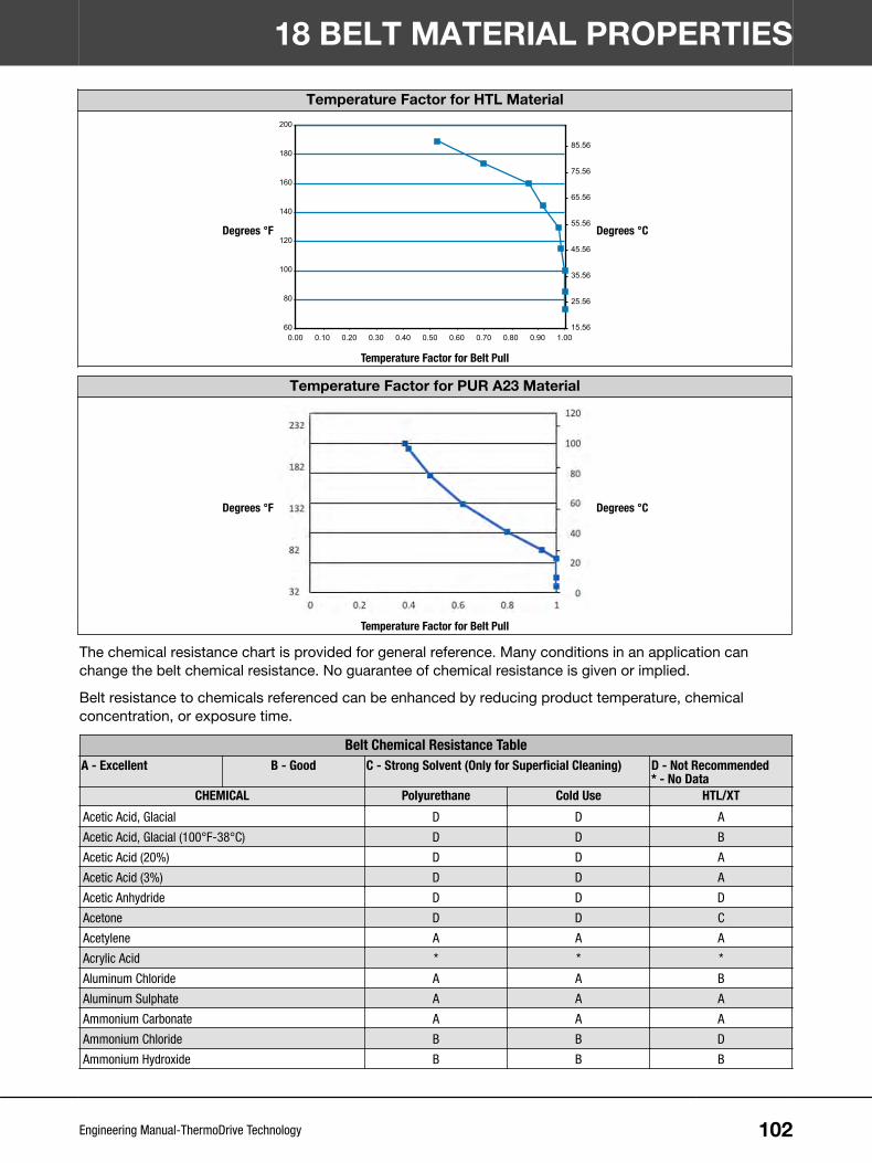
Temperature Factor for HTL Material
Degrees °F
15.56
25.56
35.56
45.56
55.56
65.56
75.56
85.56
60
80
100
120
140
160
180
200
0.00 0.10 0.20 0.30 0.40 0.50 0.60 0.70 0.80 0.90 1.00
Degrees °C
Temperature Factor for Belt Pull
Temperature Factor for PUR A23 Material
Degrees °F Degrees °C
Temperature Factor for Belt Pull
The chemical resistance chart is provided for general reference. Many conditions in an application canchange the belt chemical resistance. No guarantee of chemical resistance is given or implied.
Belt resistance to chemicals referenced can be enhanced by reducing product temperature, chemicalconcentration, or exposure time.
Belt Chemical Resistance TableA - Excellent B - Good C - Strong Solvent (Only for Superficial Cleaning) D - Not Recommended
* - No DataCHEMICAL Polyurethane Cold Use HTL/XT
Acetic Acid, Glacial D D A
Acetic Acid, Glacial (100°F-38°C) D D B
Acetic Acid (20%) D D A
Acetic Acid (3%) D D A
Acetic Anhydride D D D
Acetone D D C
Acetylene A A A
Acrylic Acid * * *
Aluminum Chloride A A B
Aluminum Sulphate A A A
Ammonium Carbonate A A A
Ammonium Chloride B B D
Ammonium Hydroxide B B B
18 BELT MATERIAL PROPERTIES
102Engineering Manual-ThermoDrive Technology

Belt Chemical Resistance TableA - Excellent B - Good C - Strong Solvent (Only for Superficial Cleaning) D - Not Recommended
* - No DataCHEMICAL Polyurethane Cold Use HTL/XT
Ammonium Nitrate A A A
Ammonium Nitrite A A A
Ammonium Persulfate * * *
Ammonium Phosphate A A A
Ammonium Sulphate A A B
Ammonium Sulfide A A A
Amyl Acetate D D B
Amyl Alcohol A A A
Aniline D D D
Animal Oils & Fats A A A
Anti-Freeze B B B
Asphalt B B B
ASTM Oil #1 (300°F-149°C) A A A
ASTM Oil #3 (300°F-149°C) A A A
ASTM Reference Fuel A (158°F-70°C) A A A
ASTM Reference Fuel B (158°F-70°C) B B A
ASTM Reference Fuel C B B A
ASTM Reference Fuel C (158°F-70°C) B B B
Barium Chloride A A B
Barium Hydroxide A A A
Barium Sulfide A A A
Beer A A A
Beet Sugar Liquors A A A
Benzene C C A
Borax A A A
Boric Acid B B A
Brake Fluid D D B
Bromine, Anhydrous Liquid D D D
Butane A A A
Butter A A A
Butyl Acetate D D B
Butyric Acid * * *
Calcium Bisulfite D D D
Calcium Chloride B B A
Calcium Hydroxide A A A
Calcium Hypochlorite (5%) A A A
Calcium Nitrate A A A
Calcium Sulfide A A A
Caliche (Sodium Nitrate) D D B
Cane Sugar A A A
Carbon Bisulfide B B A
Carbon Dioxide A A A
Carbon Monoxide A A A
Carbon Tetrachloride B B D
Castor Oil B B A
18 BELT MATERIAL PROPERTIES
103Engineering Manual-ThermoDrive Technology

Belt Chemical Resistance TableA - Excellent B - Good C - Strong Solvent (Only for Superficial Cleaning) D - Not Recommended
* - No DataCHEMICAL Polyurethane Cold Use HTL/XT
Cheese A A A
Chinawood Oil B B A
Chlorine Gas, Dry D D D
Chlorine Gas, Wet D D D
Chloroacetic Acid D D D
Chlorobenzene D D D
Chloroform D D B
Chlorosulphonic Acid D D D
Chromic Acid D D D
Citric Acid A A A
Coconut Oil A A A
Copper Chloride A A B
Copper Sulphate A A A
Corn Oil A A A
Cottonseed Oil A A A
Cresol D D D
Creosote B B A
Cyclohexane B B A
Cyclohexanone D D D
Denatured Alcohol C C C
Diesel Oil B B A
Dibutyl Phthalate A A A
Diethyl Sebacate A A A
Diethyl Ether B B B
Dimethyl Acetamide D D D
Dimethyl Formamide D D B
Dimethyl Sulphexide D D D
Dioctyl Phthalate (DOP) A A A
DUAL, Trademark of Ciba Geigy Corp A A A
Epichlorohydrin D D D
Ethanol C C A
Ethyl Acetate D D B
Ethyl Cellulose D D D
Ethylene Chloride D D D
Ethylene Dichloride D D D
Ethylene Glycol A A A
Ethylene Oxide A A A
Ferric Chloride B B B
Ferric Sulphate B B B
Fertilizer B B B
Fish Oil A A A
Flour A A A
Fluosilicic Acid B B D
Formaldehyde (40%) B B B
Formic Acid D D B
18 BELT MATERIAL PROPERTIES
104Engineering Manual-ThermoDrive Technology

Belt Chemical Resistance TableA - Excellent B - Good C - Strong Solvent (Only for Superficial Cleaning) D - Not Recommended
* - No DataCHEMICAL Polyurethane Cold Use HTL/XT
Freon, DuPont (11, 12, 113, 114) A A A
Fruit Acids A A A
Fuel Oil B B A
Furfural C C C
Gasoline B B A
Glucose A A A
Glue A A A
Glycerin A A A
Hexane A A A
Hexanol A A A
Hydraulic Oils B B B
Hydrazine D D D
Hydrochloric Acid (37%) D D D
Hydrochloric Acid (20%) D D B
Hydrochloric Acid (3%) D D B
Hydrocyanic Acid D D D
Hydroflouric Acid (75%) D D D
Hydroflouric Acid (48%) D D D
Hydroflouric Acid, Anhydrous D D D
Hydrogen A A A
Hydrogen Peroxide C C C
Hydrogen Sulphide B B A
Iodine D D D
Isooctane A A A
Isopropyl Alcohol C C A
Javelle Water (0.5%) D D D
JP-4 Jet Fuel B B B
Kerosene B B A
Lacquer Solvents D D D
Lactic Acid B B A
Lard A A A
Lineolic Acid D D B
Linseed Oil B B A
Lubricating Oils B B B
Magnesium Chloride A A A
Magnesium Hydroxide B B B
Magnesium Sulfate A A A
Meat & Bone Meal A A A
Mercuric Chloride D D D
Mercury D D D
Methyl Alcohol (Methanol) C C A
Methyl Isobutyl Ketone (MIBK) C C C
Methyl Ethyl Ketone (MEK) C C C
Methylene Chloride D D D
Milk A A A
18 BELT MATERIAL PROPERTIES
105Engineering Manual-ThermoDrive Technology

Belt Chemical Resistance TableA - Excellent B - Good C - Strong Solvent (Only for Superficial Cleaning) D - Not Recommended
* - No DataCHEMICAL Polyurethane Cold Use HTL/XT
Mineral Oils A A A
Mineral Spirits C C A
Molasses A A A
Mustard A A A
Naphthalene C C C
Nickel Chloride B B A
Nickel Sulphate B B A
Nitric Acid (20%) D D D
Nitric Acid (3%) D D B
Nitric Acid, Red Fuming D D D
Nitrobenzene D D D
Nut Oil A A A
Oils & Fats A A A
Oleic Acid B B A
Oleum D D D
Olive Oil A A A
Oxalic Acid B B B
Ozone D D D
Palm Kernel Oil A A A
Palmitic Acid B B B
Peanut Oil A A A
Pentane A A A
Paraffin A A A
Perchloroethylene D D D
Petroleum B B B
Phenol D D D
Phosphoric Acid, Diluted B B B
Pickling Solution (20% Nitric Acid, 4% HF) D D D
Pickling Solution (1% Nitric Acid, 4% HF) B B B
Pine Resin A A A
Potassium Chloride A A A
Potassium Dichromate A A A
Potassium Hydroxide B B B
Potassium Nitrate A A A
Potassium Sulphate A A A
Pydraul 312, Trademark of Monsanto Inc. A A A
Pyridine D D D
Rosemary Oil A A A
SAE 10 Oil A A A
Salt Water A A A
Shellac B B A
Silicone A A A
Skydrol 500B, Trademark of Monsanto, Inc. A A A
Soap Solutions A A A
Soda Ash B B B
18 BELT MATERIAL PROPERTIES
106Engineering Manual-ThermoDrive Technology

Belt Chemical Resistance TableA - Excellent B - Good C - Strong Solvent (Only for Superficial Cleaning) D - Not Recommended
* - No DataCHEMICAL Polyurethane Cold Use HTL/XT
Sodium Bisulfate B B A
Sodium Chloride (25%) B B A
Sodium Citrate D D B
Sodium Dichromate (20%) D D B
Sodium Hydroxide (46%) D D D
Sodium Hydroxide (3%) (Lye) B B B
Sodium Hypochlorite (3%) (Bleach) B B B
Sodium Nitrate (25%) B B B
Sodium Nitrate (3%) A A A
Sodium Propionate D D B
Sodium Sulfite (3%) B B B
Soy Bean Oil A A A
Stannous Chloride (15%) B B B
Steam (212°F-100°C) C C A
Steam (230°F-110°C) C C A
Stearic Acid B B B
Styrene D D B
Sulphur, Molten D D D
Sulphur Dioxide, Liquid D D B
Sulphur Dioxide, Gas D D D
Sulphuric Acid (20%) D D D
Sulphuric Acid (10%) * * *
Sulphuric Acid (3%) B B B
Sulphurous Acid B B B
Sugar A A A
Tannic Acid (10%) A A A
Tar B B B
Tartaric Acid B B B
Tetrahydrofuran D D D
Tobacco A A A
Toluene C C B
Tomato Juice A A A
Tomatoes, Ketchup A A A
Treflan, Trademark of Elanco, Inc. B B B
Tetrachloroethylene D D D
Trichloroethylene C C B
Triethanolamine (3%) D D D
Tricresyl Phosphate B B B
Trisodium Phosphate A A A
Tung Oil A A A
Turpentine C C B
Urea (3%) B B A
Urine B B B
Vegetable Oils & Fats A A A
Vinegar A A A
18 BELT MATERIAL PROPERTIES
107Engineering Manual-ThermoDrive Technology

Belt Chemical Resistance TableA - Excellent B - Good C - Strong Solvent (Only for Superficial Cleaning) D - Not Recommended
* - No DataCHEMICAL Polyurethane Cold Use HTL/XT
Water (72°F-22°C) A A A
Water (158°F-70°C) A A A
Water (212°F-100°C) C C A
Whiskey & Wine A A A
Xylene B B B
Zinc Chloride B B B
Zinc Sulphate B B B
18 BELT MATERIAL PROPERTIES
108Engineering Manual-ThermoDrive Technology

CONTACT
© 2021 Intralox, L.L.C. 5010425_EN-US
Intralox, L.L.C. USA, New Orleans, LA, +504-733-0463, Toll Free: 1-800-535-8848Intralox, L.L.C. Europe, Amsterdam, The Netherlands, +31 (0)20-540 36 00, Toll Free: 800-4687-2569Intralox Shanghai LTD., Shanghai, China, Toll Free: 4008-423-469Global Assembly Center Locations: Japan • United Kingdom • Australia • Brazil • India
Country- and industry-specific toll-free phone numbers and Intralox global location information is available at www.intralox.com