engineering guide ag-tfx-1.0 01-16-15 - titus … tfx ag.pdffan application review fan laws 3...
TRANSCRIPT

Engineering Guide AG-TFX-1.0 01-16-15
605 Shiloh Road • Plano, Texas 75074 • 972-212-4800
All rights reserved. No part of this work may be reproduced or transmitted in any form or any means, electronic or mechanical, including photocopying and recording, or by any information storage retrieval system without permission in writing from Air Distribution Technologies
REVOLUTION TFX AIR HANDLING UNITS
Application & Engineering Guide

FAN APPLICATION REVIEW
Fan Laws.....................................................3
Variable Air Volume.....................................4
Component Temperature Margins ..............5
Fan Motor Heat............................................5
COIL OPTIONS
Cooling Coils................................................6
Heating Coils................................................7
Typical Application of AH Coils....................8
REVOLUTION SEGMENT IDENTIFICATION
Segment Listing ...........................................9
Unit & Coil Hand Selection...........................9
FAN SEGMENTS – FS, FR, FE
Fan Applications ..........................................10
Dual Fan Considerations .............................10
Dual Fan Applications...................................10
Door and Discharge Locations.....................11
Single Fan DWDI Options............................12
Single Fan SWSI Options.............................13
Dual Fan DWDI Options ..............................14
Dual Fan SWSI Options ...............................15
SWSI vs. DWDI.............................................16
Fan Motor Control Methods..........................17
COIL SEGMENTS
Cooling (CC).................................................18
Heating (HC) ................................................18
Vertical Coil (VC)..........................................19
STAGGERED COIL OPTIONS
Angle Wall......................................................20
Back-to-Back .................................................20
Multi-zone (MZ) ..............................................21
HEATING SEGMENTS
Integral Face & Bypass...................................22
Indirect Gas-Fired...........................................23
Turndown Examples and Guidelines..............24
Electric Heat Options & Applications..............25
ENERGY RECOVERY
Heat Wheel .....................................................28
FILTER SEGMENTS
Applications & Options Table..........................29
Mechanical Air Filters .....................................30
MERV Analysis ...............................................31
MIXING SEGMENTS & ECONOMIZERS
Mixing Box /Economizers ...............................32
Mixing Box Optimization Chart .......................34
Typical Economizer Application......................35
Building Pressurization ...................................35
Methods of Pressurization Control .................36
Economizer Arrangements .............................36
Face Damper...................................................37
Inlet Plenum....................................................37
ACCESSORY SEGMENTS
Diffuser Segment............................................38
Access Segment ............................................38
Vertical Plenum ..............................................39
Discharge Plenum ..........................................39
Sound Attenuator ...........................................40
Noise and Vibration ........................................41
Air Blender - Mixers ........................................42
Face & Bypass Damper Segment ..................43
Turning Segments ..........................................44
Humidifier Segment ........................................44
UV Segment ...................................................45
Pipe Chase Enclosure ....................................46
POWER WIRING OPTIONS
Power Wiring Options .....................................47
INDUSTRY FORMULAS
Miscellaneous Industry Formulas ...................48
TABLE OF CONTENTS
FIG. 1 – BASIC REVOLUTION TFX WITH MIXING BOX, RIGID FILTER,
COOLING COIL, AND SUPPLY FAN

FAN APPLICATION REVIEW
Fan Laws (Recommended Accepted Practice)
The fan laws are used to calculate performance characteristics; fan speed (RPM), fan air capacity (CFM), static pressure (SP) and brake horsepower (BHP) of a particular fan at conditions other than those at which the data was taken.
By using the fan laws in conjunction with a fan curve, the fan performance can be calculated accurately at various operating conditions. Every fan has its own unique fan curve. FIG. 2 shows a fan curve at various RPMs.
The system resistance curve relates the total pressure loss in an air handling system to the flow rate of air through the system. The system curve is unique to each system because it expresses the pressure losses associated with the system. (AHU cabinet, coils, filters, supply and return ductwork, grilles and diffusers).The SP and CFM values are used to create the system curve for the particular system. FIG. 3 represents a fan curve with 2 system curves identified.
System curves will always have a square function
slope (parabola) because the SP varies as a square
of the CFM. The point where the system curve
intersects the RPM curve is the operating point of the
fan (point A). If the system resistance changes (i.e.,
dirty filters or change in ductwork), the operating
point will move along the RPM curve to a different
operating point and therefore, new system curve
(point B). With a fixed system, the effects of change
in RPM, air density of BHP can be calculated and
plotted on the system curve by using the following fan
laws:
The fan laws can only be used to project
performance along a specific system curve.
Referencing FIG. 3, Point A can be used to project
the performance of Point C and similarly, Point B
can be used to project the performance of Point D.
Point A cannot be used to predict any other point on
the RPM curve, it can only project performance on
the system curve created by Point A.
• The CFM varies directly with the RPM:
• The SP varies as a square of the RPM:
• The BHP varies as a cube of the RPM:
• The SP and BHP are directly proportional
to the air density:
FIG. 2 – CURVE AT VARIOUS RPMs
FIG. 3 – FAN CURVE WITH TWO SYSTEM CURVES3

FAN APPLICATION REVIEW
Variable Air Volume
A common mistake when selecting a fan with variable air volume is to assume a fan with VAV will follow a constant design system curve (passing through the point 0 CFM and 0 TSP) to maintain control. VAV systems do not have a constant system line, but rather a range of operating points necessary to satisfy the building requirements. In VAV systems, the operating point will continue to move based on the air modulation and as the CFM and SP change, the fan is modulated to match the new requirements, developing its own system curve. This modulation is accomplished by using inlet vanes, variable speed drives or discharge dampers. Before finalizing the fan selection, plot the new VAV system curve to confirm the modulation range required does not enter into the instability range of operation.
Example
Calculate the minimum CFM and at least 2 arbitrary points which fall within the stable operating range of the curve (using equations below) and plot these points along with the design points to create the new VAV system. (See FIG. 4.)
Design CFM = 40,000 CFM = CFMd Design TSP = 4.5 in WG = SPd Static Pressure Control Point = 1.25 in WG = SPd
Select the most efficient fan that can deliver both the
design and minimum CFM requirements. If the initial
selection does not provide sufficient “turn down”,
select the next smallest fan and re-plot the VAV
system for the smaller fan and re-evaluate. Typically,
the largest fan that can supply the required
modulation is the most efficient. Each application
should be considered individually and evaluated to be
sure the fan will not be forced into the unstable region
at modulated condition.
For variable speed drive (VSD) applications, the fan
drive assembly is selected to operate approximately
in the middle of the VSD’s range. When selecting a
fan to be used with a VSD, if the RPM is close to or
approaching the Class I limit, select the Class II fan.
Selection of a Class I fan may result in premature
bearing failure.
4

Revolution TFX Component Temperature Margins
• Standard motors (Class B Insulation) -104°F.
• Motors with Class F Insulation -140°F.
• Power Wiring - 140°F.
• Controls & Control Wiring - 140°F.
• Pre-filters - 150°F.
• High Efficiency Filters - 200°F.
• Fan Bearings - 120°F (FC), 180°F (AF)
• Gasketing - 200°F
• Foam - Flash Point: 415°F (213°C)
FIG. 4 – FAN CURVE AT VARIOUS RPMs
5
COIL OPTIONS
Flexibility and Performance illustrate the variety of coils which are available to meet every application. These carefully engineered coils are designed for an optimum balance between air pressure drop and heat transfer coefficient, to allow the maximum amount of cooling or heating capacity without the added expense of high air-pressure drops. The coil designs are subjected to constant extensive evaluation studies comparing different fin corrugations with various tube arrangements.The Titus rep in your area will welcome the opportunity to assist you with your coil applications.
Cooling Coils – Water and Direct Expansion
Revolution optimizes coil performance with customized coil options. Revolution coils are offered in a wide variety of types, sizes, arrangements and materials. Coil software optimizes capacity and pressure drop requirements.
AHU Chilled water cooling coil
• Available in CC, VC, MZ segments
AHU Hot water heating coil
• Available in CC, VC, HC, MZ segments
AHU (DX) Direct Expansion cooling coil
• Available in CC, VC, MZ segments
Header material:
• Copper
• Red Brass
Connector material:
• Red brass
• Steel
Connection Type:
• MPT
• Grooved
Fin type:
• 5/8” tube: Sine or Flat
• 1/2” tube: Sine corrugated only
Fin Material & Thickness:
• Aluminum - 0.006”, 0.008”, 0.010”
• Copper - 0.006”
Fin Spacing:
• A vast range of fi ns per inch available
Fin Coatings: (Coatings reduce max face velocities)
• Electro-fi n
• Phenolic
• Heresite
Coil Casing:
• Galvanized
• Stainless Steel
Choice of heat transfer medium:
• Water, Glycol (Ethylene glycol coils are ARI certified)
• DX – (a variety of refrigerants to choose from)
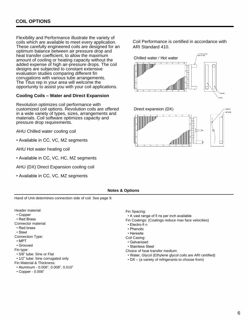
Coil Performance is certified in accordance with
ARI Standard 410.
Notes & Options
Hand of Unit determines connection side of coil. See page 9.
6

Heating Coils – Integral face and bypass
Integral face and bypass coils have alternating channels of heat transfer surface and bypass zones. The air flow is directed over the heat transfer surface or through the by-pass zone by modulating dampers that are integral with the coil construction.
Integral face and bypass coil (IFB/VIFB)
• Coils are available in the ‘IC’ segment
• Tubes either Vertical or Horizontal
• Coils for maximum freeze protection
• Hot water or Steam coils
• Multiple rows deep
Heating Coils – Steam Distributing
The construction of a Steam Distributing Coil is entirely different than that of a Standard Steam.
Everyplace that you see an outside tube or header, there is an inside tube and header that you can’t see. Steam is distributed through these inside tubes and headers and slowly released to the outside tubes as the steam turns to condensate. The condensate then flows back down the outside tubes in the same direction that the entering steam comes from. The idea is that all the steam in the inside tubes keeps the condensate in the outside tubes from freezing when air passes across the coil at lessthan 32° F. However, under exactly the correct conditions, even steam distributing coils can freeze.
Steam Distributing - 1” diameter tube • Available in CC, VC, HC, MZ segments
• A vast range of fi ns per inch available
• Multiple tube wall thickness options
Notes & Options
Coil Style:
• IFB
• VIFB
Coil Type:
• Water (Glycol)
• Steam
Rows:
• 1,2,3,4
Connection:
• SCH 40 pipe
Thermostat:
• None
• Electric
Fin Material:
• Aluminum
Fin Spacing:
• A range of fi ns per inch available
Coil Casing:
• Galvanized
Steam or Hot Water
INTEGRAL FACE & BYPASS (IFB) COIL
Steam
7

COIL OPTIONS
Typical Application of Air Handling Coils
Heating Coils
Heating coils can use steam or hot water to add heat to the air stream. In a cooling-only VAV system, the heating coil is generally placed in the ‘preheat’ position between the filters and cooling coil. The preheat coil can be omitted in this system if the minimum outside air requirement is low and would not result in a mixed air temperature below 50° F to 55° F.
Heating coil capacity is controlled by means of a modulating control valve in the water or steam piping. The control valve position is usually controlled by means of a thermostat in the supply air duct in sequence with the cooling coil control valve.
Cooling Coils
Cooling coils remove both sensible and latent heat from the mixed air and can use chilled water, chilled brine, or refrigerant as the cooling source. In the case of chilled water, the supply water temperature generally ranges from 42° F to 50° F, depending on the latent load to be removed. Brine or a solution of ethylene or propylene glycol in water is traditionally used at temperatures of 32° F to 40° F for applications in which piping is exposed to freezing temperatures. Control of the cooling coil capacity at the air-handling unit is achieved by means of a two-way ‘throttling’ or three-way ‘mixing’ control valve. In VAV systems, a supply duct thermostat is typically used to modulate the control valve so as to maintain a constant temperature of air leaving the unit, usually 55° F to 60° F.
When refrigerant is used as the cooling source, it enters the coil in liquid form from a condensing unit and provides cooling by a process called ‘direct expansion’. The liquid refrigerant evaporates as the warmer air moves across the coil, removing heat from the air during the process. The evaporated refrigerant is then compressed in the condensing unit, which also houses the condensing coil where the heat is rejected to the outside. Control of the coil capacity is typically by means of a series of
solenoid valves in the refrigerant liquid lines, which are energized to shut-off the flow of refrigerant to part of the coil. There are several problems with the application of VAV to a direct expansion (DX) coil which require the designer to take special precautions when considering this system. First, the balance point temperature for the DX coil will change as the air flow rate changes. Assuming constant coil capacity, reducing the CFM will reduce the suction temperature and pressure, making close control of air temperature difficult. In addition, compressor unloading at reduced load will cause step changes in capacity and suction temperature, which can cause hunting in the flow control loop. In short, the use of variable air flows with a DX coil requires careful consideration of the effect air flow changes make to the system. Balance point temperatures must be carefully considered.
Design Considerations
In order to insure predicted coil performance, air distribution must be uniform. There are two design checks for this:
1. ‘45 degree rule’ – This rule states that the performance of the coil will not be affected as long as the diffusion angle from the most restrictive block-off to the finned portion of the coil is 45 degrees or less. This rule holds true unless there are unusual flow fields, caused by such components as upstream fans or mixing boxes where not applied properly.
2. ‘Uniform pressure rule’ – This rule states that the performance of the coil will not be affected as long as the maximum difference in upstream, downstream, and combined static pressure due to local velocity pressure at any one point on the coil compared to another point that does not exceed 10 percent of the pressure drop through the coil. The basis for this rule is that the flow rate through the coils at any one point is a function of the local upstream and downstream pressures, and if pressure differences are small, distribution will be uniform.
8

REVOLUTION TFX SEGMENT IDENTIFICATION
FAN SEGMENTS
• FS – Supply
• Forward Curved
• Airfoil
• Industrial Airfoil
• SWSI Plenum
(Belt and Direct Drive)
• FR – Return
• Forward Curved
• Airfoil
• Industrial Airfoil
• SWSI Plenum
(Belt and Direct Drive)
• FE – Exhaust
• Forward Curved
• Airfoil
• Industrial Airfoil
COIL SEGMENTS
• CC – Cooling Coil
• HC – Heating Coil
• VC – Vertical Coil
• MZ - Multizone
HEAT SEGMENTS
• IC – Integral Face & Bypass Coil
• IG – Indirect Gas Fired Furnace
• EH – Electric Heater
ENERGY RECOVERY
• ER – Energy Recovery
FILTER SEGMENTS
• FF – Flat Filter (2” or 4”)
• AF – Angle Filter (2” & 4”)
• RF – High Efficiency Filter
• Rigid Filter (12”)
• Bag Filter (21”)
• Mini-Pleat Filter (4”)
INLET SEGMENTS
• MB – Mixing Box
• FM – Filter/Mixing Box
• EF – Filter/Economizer
• EE – Economizer
• IP – Inlet Plenum
• VE – Vertical Economizer
• VF – Vertical Filter/Economizer
ACCESSORY SEGMENTS
• VP – Vertical Plenum
• DP – Discharge Plenum
• TN – Turning Plenum
• DI – Diffuser
• XA – Access segment
• AB- Air Blender
• EB – External Bypass
• IB – Internal Bypass
• FD – Face Damper
• AT – Attenuator
• HM - Humidifier
• UV - UVC Lamps
Unit & Coil Hand Identification
9

SINGLE FAN SEGMENT – FS, FR AND FE
Fan Applications
Fan segments are available as supply, return and or exhaust applications. Unit configurations have a
segment option of utilizing a single fan or a dual fan arrangement. Isolation consists of 1" or 2" springs with
a seismic snubber option. Thrust restraints and OSHA belt guards are available as required.
Double-width/Double-inlet (DWDI)
• Forward Curve or Airfoil centrifugal
• Belt Driven
Single-width/Single-inlet (SWSI)
• Airfoil plenum
• Belt Drive or Direct Drive
In most fan systems a segment with a single fan
is adequate for the required system design and
rating. Methods of control can vary and may
include dampers or variable speed drives. Also
included in a single fan design may be the
allowance for future expansions.
Bearing options for fans with lubricating bearings:
(refer to Notes & Options)
• Extended Lube Line
• External Lube Line
In some situations, there may be a need for a system design using dual fans in a cabinet. The following
are some reasons to consider a dual fan arrangement:
Dual Fan Considerations
1. One fan may be too large and not fi t into the desired
space, or it may weigh too much if supported on
upper levels.
2. The required operating range of the system may
necessitate multiple fans instead of one large fan
controlled over a wide operating range.
3. Dual fans for capacity control may be more
economical if cost of operation is critical, especially at
very low flow rates for long time intervals.
4. Critical systems are often equipped with
redundant or back-up fans in case of a fire or
accident or some other emergency that requires
a sudden increase in flow. Redundant fans are
also used to eliminate downtime during fan
maintenance.
5. Some systems for process applications may
require pressures that are greater than a single
fan can produce or when noise may be a special
concern.
Dual Fan Applications
Revolution dual fan application methods include 50/50 where both fans operate together to share the load
equally or 100/100 where only one fan at a time is in operation.
• In a 50/50 application, the failure of one fan will result
in a condition where the other fan will continue
to operate. The single fan will provide partial load
capabilities
• In a 100/100 application, the failure of one fan will
result in the operation of the other (standby) fan to
provide full capacity
10
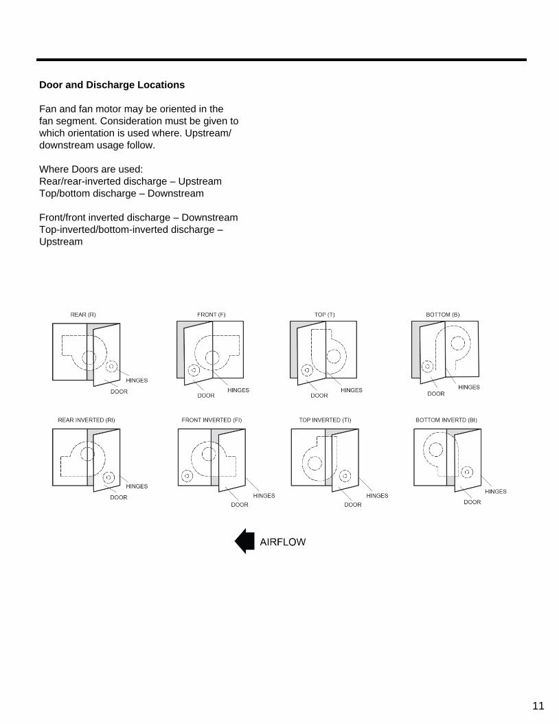
Door and Discharge Locations
Fan and fan motor may be oriented in the
fan segment. Consideration must be given to
which orientation is used where. Upstream/
downstream usage follow.
Where Doors are used:
Rear/rear-inverted discharge – Upstream
Top/bottom discharge – Downstream
Front/front inverted discharge – Downstream
Top-inverted/bottom-inverted discharge –
Upstream
11
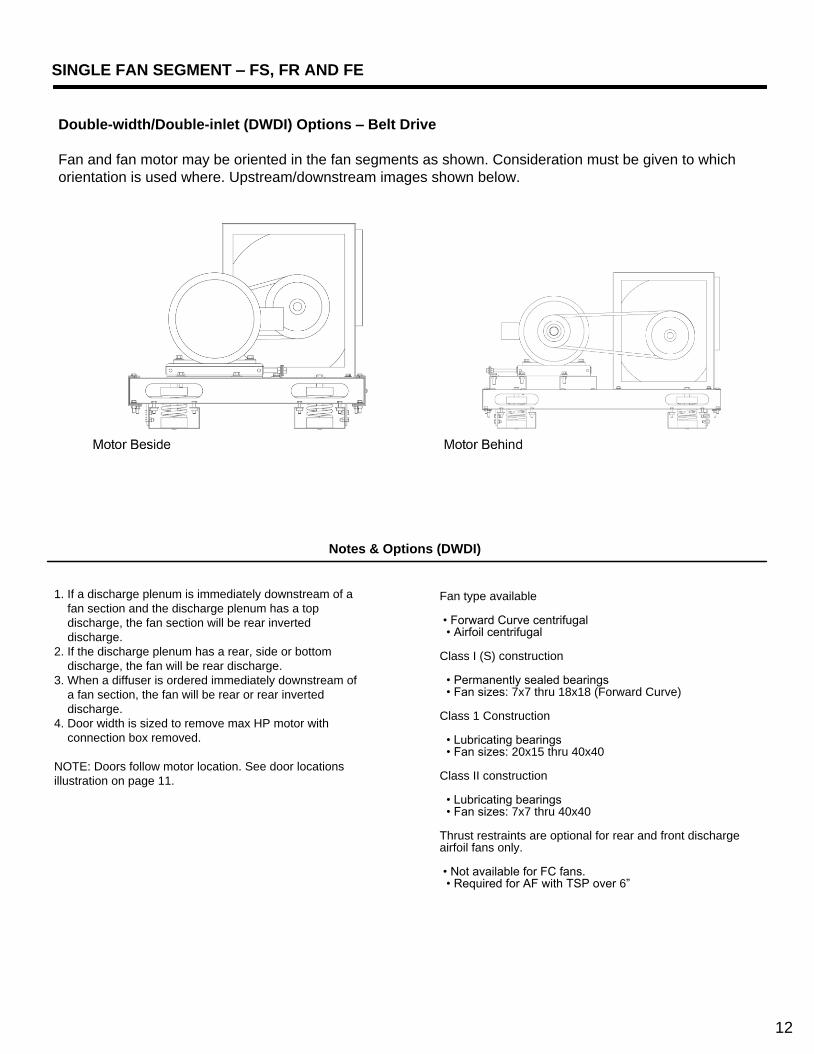
SINGLE FAN SEGMENT – FS, FR AND FE
Double-width/Double-inlet (DWDI) Options – Belt Drive
Fan and fan motor may be oriented in the fan segments as shown. Consideration must be given to which
orientation is used where. Upstream/downstream images shown below.
Notes & Options (DWDI)
1. If a discharge plenum is immediately downstream of a
fan section and the discharge plenum has a top
discharge, the fan section will be rear inverted
discharge.
2. If the discharge plenum has a rear, side or bottom
discharge, the fan will be rear discharge.
3. When a diffuser is ordered immediately downstream of
a fan section, the fan will be rear or rear inverted
discharge.
4. Door width is sized to remove max HP motor with
connection box removed.
NOTE: Doors follow motor location. See door locations
illustration on page 11.
Fan type available • Forward Curve centrifugal • Airfoil centrifugal
Class I (S) construction
• Permanently sealed bearings • Fan sizes: 7x7 thru 18x18 (Forward Curve)
Class 1 Construction
• Lubricating bearings • Fan sizes: 20x15 thru 40x40
Class II construction
• Lubricating bearings • Fan sizes: 7x7 thru 40x40
Thrust restraints are optional for rear and front discharge airfoil fans only. • Not available for FC fans. • Required for AF with TSP over 6”
12

Notes & Options (SWSI)
1. The plenum fan segments can accommodate multiple
duct outlets, thus reducing the amount of field duct
work and transitions.
2. When any filter segment (EF, FM, FF, AF, RF, or HF)
or coil segment (CC or HC) is located upstream of a
FS-SWSI, FR-SWSI or FE-SWSI, sufficient transition
length will be required between the FS segment and
the filter segment.
3. Fan discharge locations - rear, front, bottom, top, left and right.
4. Single Width, Single-Inlet (SWSI) air foil plenum fans are
available as Class I, II & III. (with lubricating bearings)
5. Thrust restraints are required with TSP over 3”.
Single-width/Single-inlet (SWSI) Options
Fan and fan motor may be oriented in the fan segments as shown. Consideration must be given to which
orientation is used where. Upstream/downstream images shown below.
13

DUAL FAN SEGMENT – FS, FR AND FE
Notes & Options
Double-width/Double-inlet (DWDI) Options – Belt Drive
Fan type available:
• Forward Curve centrifugal • Airfoil centrifugal
Class I (S) construction • Fan sizes: 7x7 thru 18x18 (Forward Curve)
Class 1 construction • Fan sizes: 20x15 thru 22x22
Class II construction • Fan sizes: 7x7 thru 22x22
DWDI motor location – Behind only
Access doors are provided on both sides of the segment.
• Allow sufficient access-to and clearance-around the
segment for motor removal from either side.
Separation Panel Option
• Optional safeguard when servicing requires that the
system be in a running status. A separation panel is
positioned between the fans.
Flow Isolation Options
• Optional isolation method to prevent air from an
energized fan going back through a fan that is not
energized.
• DWDI option is mounted on fan discharge.
• Note: Not available with fan exhaust (FE)
• Option is required with 100 %/100 % method.
Options include (depending on type of fan):
1. Manual sliding panel
2. Back-draft damper with counter balance
3. Mechanical Control damper
14

Single-width/Single-inlet (SWSI) Options – Belt-Drive or Direct Drive
Fan type available:
• Standard Airfoil (AF) 10" – 30" • *Industrial Airfoil (AF) 12" – 30"
• Class I, II, *III
SWSI motor location: • 10" to 16" fans - behind motor only • 18" to 30" fans - top motor only • Fans with top motor location will require thrust restraint
Notes & Options
Access doors are provided on both sides of the segment.
• Allow sufficient access-to and clearance-around the
segment for motor removal from either side.
Separation Panel Option
• Optional safeguard when servicing requires that the
system be in a running status. A separation panel is
positioned between the fans.
Flow Isolation Options
• Optional isolation method to prevent air from an
energized fan going back through a fan that is not
energized.
• SWSI option is mounted on fan inlet.
• Note: Not available with fan exhaust (FE)
• Option is required with 100 %/100 % method.
Options include (depending on type of fan):
1. Manual sliding panel
2. Back-draft damper with counter balance
3. Mechanical Control damper
15

FAN SEGMENT – FS, FR AND FE
SWSI Plenum vs. DWDI Housed Fan Application
SWSI Plenum airfoil fans offer superior performance
for many applications. Typical concerns with fan
performance are efficiency, noise, and air velocity
profile through components. Plenum fans offer
advantages for all three concerns. Additionally, these
fans provide flexibility with outlet configurations,
reduced mechanical space footprint, and the benefit
of direct-drive.
Efficiency:
DWDI housed fans use a scroll to increase their
efficiency. However, optimizing this fan requires a
process referred to as “static regain”. Housed fans
are tested with an outlet duct of 2.5 to 3.5 times the
wheel diameter in length. This outlet duct allows the
“static regain” process, where velocity pressure is
converted to static pressure. Housed fans applied
without this outlet duct will require a system effect
factor (SEF) which decreases the fan efficiency.
Housed fans in blow-through positions will also
require an air diffuser which decreases the efficiency
further. The combination of these two system effects
brings even the best housed DWDI airfoil fan
efficiency to, or below that, of the SWSI plenum fan,
thereby eliminating the benefit of the fan scroll.
Noise:
Plenum fans have the benefit of effectively utilizing
the entire unit as the fan housing, which offers
superior attenuation. The same factors that decrease
the housed fan’s efficiency discussed above also
increase the noise level of the housed fan. Also,
since the SWSI plenum fan has no scroll, typically
there is room within the air handling unit for a larger
wheel (33” SWSI plenum vs. 27” DWDI housed, for
example), which generally produces better sound
characteristics. For design pressures at or below 6.00
in. W.C., it is very common to see supply air sound
power levels lower when using a SWSI plenum airfoil
fan instead of the DWDI housed airfoil fan.
Additionally, perforated liners may be used in plenum
fan sections for greater attenuation.
Velocity Profile:
Due to the relatively small outlet/blast area of
housed DWDI fans, an air diffuser must be applied
to the discharge of the fan to obtain an acceptable
velocity profile through the next component. Air
diffusers add static pressure which decreases fan
efficiency and increases fan noise levels. SWSI
plenum fans positively pressurize the entire cabinet,
they do not require a diffuser with its associated
performance losses.
Outlet Flexibility:
SWSI Plenum fans serve to pressure the entire fan
plenum, allowing for multiple duct take-off from the
AHU. Additionally, these openings can be tailored to
match virtually any duct configuration, be it
rectangular or round/ flat-oval with bellmouth fittings
for improved acoustic and optimized pressure drop
performance.
Mechanical Space Optimization:
A housed DWDI fan requires a straight run of duct
per AMCA guidelines at the outlet of the fan before
elbows can be applied. This constraint imposes
restrictions on duct layout and mechanical space
design which generally increase overall footprint
requirements. The ducted take-offs from pressurized
plenums, as in the case of a SWSI plenum fan, does
not have a requirement for a straight run and affords
greater flexibility to the architect and engineer in
ductwork design.
Direct-Drive Benefit:
Specialty housed DWDI fans can be used in direct-
drive arrangements, where the fan wheel is directly
mounted onto the motor shaft, most-typically,
housed fans are driven by a belt and sheave
system. Belt-drive systems typically allow for 3-5%
of efficiency loss and impose maintenance
requirements not present in direct-drive systems.
Additionally, belts wear and give off debris in the
form of belt dust. Anymore, discerning engineer’s
apply direct-driven SWSI plenum fans with VFD’s for
efficient variable air volume duty and trouble-free
maintenance.
16

Fan Motor Control Methods
Motor control options can be explained as any one of the 3 items described below.
17

COIL SEGMENT – CC, HC AND VC
Notes & Options
Notes & Options
Cooling Coil – (CC)
When cooling 100% OA there are precautions
required. Summer design conditions are such that
when air is cooled down to normal coil leaving
temperatures, there is a considerable amount of
condensate generated. Many applications suggest
cooling coils should be selected for an air velocity
under 500 FPM. If the unit is selected as a 100%
OA application, the drainage area for larger face
area coils will be increased to properly compensate
for the probable condensate.
Heating Coil – (HC)
When heating only is required the heating coil segment
is an excellent minimally sized housing which shall
accommodate a single heating coil. Coils are offered
with left or right hand connections. Coils will be
individually mounted and easily removable.
Coil segment panels (side panels and top panel) shall
be easily removable to allow for removal and
replacement of coils, without affecting the structural
integrity of the unit.
Coils
• A combination of Water and DX coils in the same
segment requires all coils to be of the same tube
diameter.
• Multiple Water coils configured in the same segment
must be of the same tube diameter.
• Steam coils may be configured with 5/8” tube coils. A
spacer must be used between a steam coil and any
water coil or DX coil.
Headers
• Usual header location is drive side.
• All headers in the same segment must exit the unit on
the same side
Door
• Usual door location is drive side
Liner – Galvanized or Stainless Steel
Coils
• Only hot water and steam coils are available in the HC
segment.
• Only one coil (hot water or steam) is permitted per segment.
Headers
• Usual header location is on the drive side.
Doors
• Doors are not available.
Drain pans
• Auxiliary drain pan is optional.
• Usual drain location is header side.
18

Notes & Options
Coils
• All coils located in the same coil segment must have
the same coil hand.
• Multiple Water coils configured in the same segment
must be of the same tube diameter.
• A combination of Water and DX coils in the same
segment requires all coils to be of the same tube
diameter.
• The steam coil is available for use in the VC segment.
Steam coils may be configured with 5/8” tube coils. A
spacer must be used between a steam coil and any
water coil or DX coil.
Headers
• Usual header location is on the drive side.
• All headers in the same segment must exit the unit on
the same side.
Doors
• Usual door location is on the drive side.
• Doors are always last in the air stream of the segment
Drain pans
• IAQ drain pan liner - Galvanized or Stainless Steel
• Usual drain location is on header side
Vertical Coil – (VC)
This segment shall provide for a 90-degree change
in airflow direction from horizontal to vertical, after
passing air through the coil space.
Coils are configured for horizontal air flow to
minimize segment length. Drains pans are
extended to assure complete condensate drainage
and coil access. Coil segment panels (side panels)
shall be easily removable to allow for removal and
replacement of coils, without affecting the structural
integrity of the unit.
19
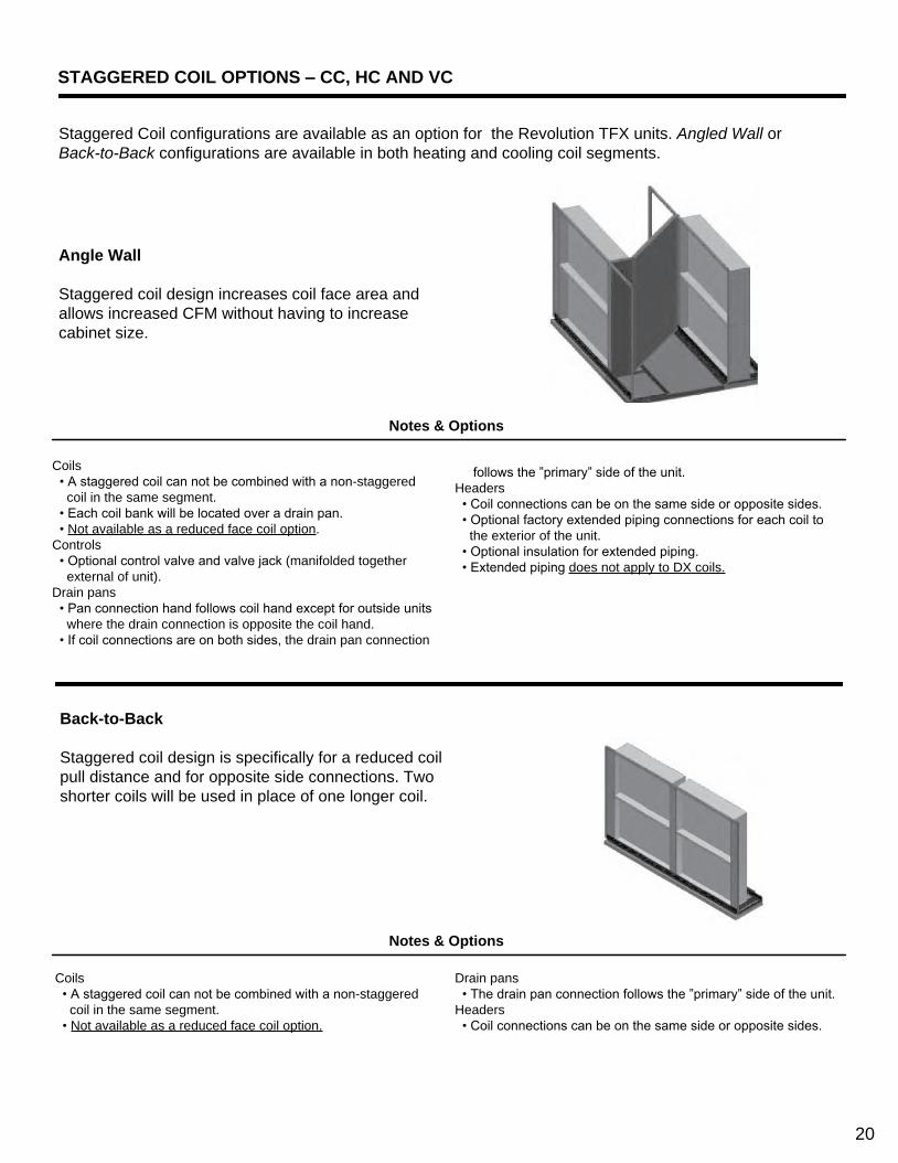
STAGGERED COIL OPTIONS – CC, HC AND VC
Staggered Coil configurations are available as an option for the Revolution TFX units. Angled Wall or
Back-to-Back configurations are available in both heating and cooling coil segments.
Angle Wall
Staggered coil design increases coil face area and
allows increased CFM without having to increase
cabinet size.
Notes & Options
Coils
• A staggered coil can not be combined with a non-staggered
coil in the same segment.
• Each coil bank will be located over a drain pan.
• Not available as a reduced face coil option.
Controls
• Optional control valve and valve jack (manifolded together
external of unit).
Drain pans
• Pan connection hand follows coil hand except for outside units
where the drain connection is opposite the coil hand.
• If coil connections are on both sides, the drain pan connection
follows the ”primary” side of the unit.
Headers
• Coil connections can be on the same side or opposite sides.
• Optional factory extended piping connections for each coil to
the exterior of the unit.
• Optional insulation for extended piping.
• Extended piping does not apply to DX coils.
Back-to-Back
Staggered coil design is specifically for a reduced coil
pull distance and for opposite side connections. Two
shorter coils will be used in place of one longer coil.
Notes & Options
Coils
• A staggered coil can not be combined with a non-staggered
coil in the same segment.
• Not available as a reduced face coil option.
Drain pans
• The drain pan connection follows the ”primary” side of the unit.
Headers
• Coil connections can be on the same side or opposite sides.
20
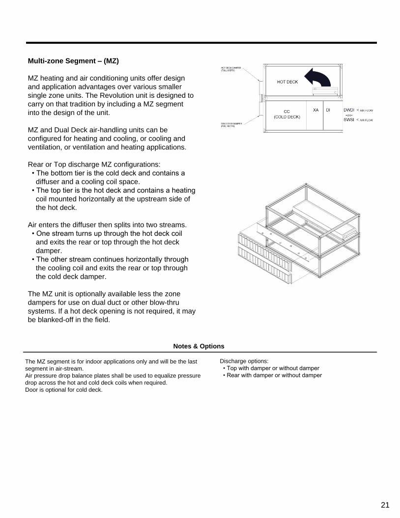
Multi-zone Segment – (MZ)
MZ heating and air conditioning units offer design
and application advantages over various smaller
single zone units. The Revolution unit is designed to
carry on that tradition by including a MZ segment
into the design of the unit.
MZ and Dual Deck air-handling units can be
configured for heating and cooling, or cooling and
ventilation, or ventilation and heating applications.
Rear or Top discharge MZ configurations:
• The bottom tier is the cold deck and contains a
diffuser and a cooling coil space.
• The top tier is the hot deck and contains a heating
coil mounted horizontally at the upstream side of
the hot deck.
Air enters the diffuser then splits into two streams.
• One stream turns up through the hot deck coil
and exits the rear or top through the hot deck
damper.
• The other stream continues horizontally through
the cooling coil and exits the rear or top through
the cold deck damper.
The MZ unit is optionally available less the zone
dampers for use on dual duct or other blow-thru
systems. If a hot deck opening is not required, it may
be blanked-off in the field.
Notes & Options
The MZ segment is for indoor applications only and will be the last
segment in air-stream.
Air pressure drop balance plates shall be used to equalize pressure
drop across the hot and cold deck coils when required.
Door is optional for cold deck.
Discharge options:
• Top with damper or without damper
• Rear with damper or without damper
21

HEATING SEGMENTS
Notes & Options
1. Coil connections must be located opposite the access door.
2. All piping to be supplied by field, coil connections are internal
from factory.
Headers:
Usual header location is on the drive side. Header location must
be opposite the access door.
Coils:
Only hot water and steam applications are available for this
segment
Doors:
Access doors and viewing ports must be located in adjacent
segments.
A door is required in the immediate downstream segment from the
IC segment.
Auxiliary Drain pans:
An auxiliary drain pan is optional.
Usual drain location:
• IFB on header side
• VIFB on left side of the unit
Integral Face & Bypass – (IC)
The Integral Face & Bypass coil controls air
temperature while full steam pressure or water flow
is maintained in the coil at all times. The
temperature of the discharge air is controlled by
proportioning the entering air through the multiple
heating and by pass channels.
Applications ideally suited for:
1. Make-up Air
2. Combustion Air Make-up
3. Penthouse units
4. Air conditioning preheat and heating/ventilating units.
Features & Benefits:
• Maximum freeze protection
• Constant volume
• Minimum temperature override
• Minimum stratification
• Accurate temperature control
22

Notes & Options
Indirect Gas-Fired Furnace – (IG)
The IG segment must be positive pressure. (Fan segment is not
allowed downstream of the IG Segment.)
Furnaces in VAV applications are designed to be used only with
100% supply fan airflow.
– Use of furnace in reduced airflow operation may result in
serious damage to equipment and may be hazardous.
– Indirect Gas-Fired Furnace Maximum Temperature rise = 90F
– Indirect Gas-Fired Furnace Maximum A.P.D. = 2.00” W.C.
– The Maximum Temperature at the IG segment discharge =
190F
Furnace includes a series stainless steel primary heat
exchanger. A secondary stainless steel heat exchanger is
also included.
– An access door is required upstream of any IG segment.
– Gas pipe train options are available
The IG segment pipe chase is a single pipe chase that
covers only the IG segment.
– The pipe chase is not intended for trapping or piping, but
for the connections only.
– Pipe chase enclosure is optional
23
HEATING SEGMENTS
Turndown Examples and Guidelines – (IG)
Description
Indirect Fired Gas Heater section consists of the
stainless steel primary and secondary heat
exchanger with the power burner design. The basic
design allows the power burner to inject the correct
ratio of air and gas into the primary heat exchanger
where the main combustion occurs. The heated
products of combustion then pass through the
multiple secondary tubes heating each tube for
maximum heat transfer. The products of combustion
then pass to the inducer draft fan and through the
flue. The air is heated by passing around the primary
and secondary tubes for optimal heat transfer. The
heater is designed for 80% efficiency.
• The furnace comes wired with all necessary
safety controls and valves installed.
• The controls vary based on the BTU level and
Insurance Requirements selected.
• These units are designed to handle Natural Gas
as a standard.
• The gas pressure available at the unit needs to be
considered when ordering the equipment.
Equations:
• BTU Output Required = CFM x 1.08 x
Temperature Rise Required
• BTU Input = BTU Output .80
The Solution furnaces are available with burner fi
ring arrangements:
• 3-1 MODULATION: The burner will modulate for
100% - 33% of full fi re
• 10-1 MODULATION: The burner will modulate
from 100% - 10% of full fi re
• 25-1 MODULATION: The burner will modulate
from 100% - 4% of full fi re
Choosing Considerations
When choosing the proper turn down three issues
should be considered.
1. Greater modulation provides improved
temperature control. If the furnace is modulated to its
minimum fire position, and controls determine there
is too much furnace capacity, then the furnace is
staged on and off, on carefully chosen time delays,
to satisfy the light load heating requirements. The 3-
1 option is generally sufficient particularly if design
temperature rise does not exceed 30-40 degrees.
2. The greater the range of modulation the greater
the cost.
3. Experience requires that a furnace should not
turn down to a temperature rise less than 5-8
degrees.
Greater modulation decreases the flue stack
temperature at low fire, increases the amount of
condensation, and can decrease the life of the heat
exchanger even though all Revolution furnaces
utilizes a stainless steel primary and stainless steel
secondary heat exchanger tubes along with
condensate drains.
The condensate line must be adequately sized,
trapped, along with drainage of the condensate per
local code.
24

Notes & Options
• Electric heaters are of “open coil” construction, with 80%
nickel, 20% chromium coil elements machine crimped to
stainless steel terminals and amply supported on
ceramic bushing isolators. Open coil heaters are
furnished with a disk-type, automatic reset thermal
cutout for primary over-temperature protection. Heaters
are also being furnished with disk-type, load-carrying
manual reset thermal cutouts, factory wired in series with
heater stages for secondary protection.
• Heaters are rated for the voltage, phase and number of
heating stages indicated in the schedule. All three-phase
heaters will have equal, balanced, three-phase stages.
• Finned tubular construction - optional
• All internal wiring shall be stranded copper with 105° C minimum
insulation and shall be terminated in crimped connectors or box
lugs.
• Power and control terminal blocks shall be provided and clearly
marked for all field wiring and shall be sized for installation of 75°
C copper wire rated in accordance with NEC Table 310-16, not
more than three conductors in a conduit.
• Heaters shall be furnished with built-in fuses per NEC. Heaters
with loads greater than 48 amps will be furnished with built-in
fusing. Heaters shall be sub-circuited into a maximum of 48 amps
per circuit. Low resistance single element fuses will be mounted
in phenolic fuse blocks fitted with extra tension springs to assure
cool connections. Fuses shall be sized at least 125% of the load.
Electric Heat – (EH)
The EH segment can be installed in either a draw
through or blow through arrangement.
Remote Mounted terminal panels
• An electric heat control panel may be selected as
a remote panel.
• In this case the panel will be shipped separate to
the customer for field installation.
An optional wide access door may be ordered on the
opposite side of the electric heater control panel.
An SCR Controller is available on all heaters with a
height dimension greater than 26.5”.
25
HEATING SEGMENTS
Typical Applications
An electric heating system will use either an open
wire element or an element encased in a sheathed
ceramic material. For most applications either
construction can be used, however, in applications
with potentially high humidity (i.e.100% OA
application), the encased element will have a longer
life expectancy and is recommended.
Selection of the proper unit, heating load and
temperature control system is dependent on the
application of the unit.
1. Make-up Air Unit is used for heating 100% OA
air to the indoor design temperature with a
typical discharge temperature of 55-70°F.
2. Space Heating Unit is used for heating 100% RA
from the conditioned space to make up for
building heat loss.
3. Combination Make-up Air & Space Heating
is used to heat OA & RA combined through a
mixing box.
Optional Control Methods
1. Proportional step control – multi-staging control
of circuits
2. SCR Controller – a time proportioning type
controller that modulates the heater and supplies
the exact amount of power to match the heat
demand. Precision controlled from zero to 100%
in direct response to the modulating thermostat
signal system. 100% step-less and noise-less
operation. *Note – SCR’s are limited to a
maximum KW. Multiple SCR’s may be applied to
larger heaters. Multiple SCR’s do not imply full
face control. See “Special Application
Considerations”.
3. Vernier Proportional Control – used on larger KW
heaters where very close heat control is
required. The system employs a combination of
SCR and non-
SCR steps. This is accomplished by satisfying
most of the heat requirement through the non-
SCR steps and then the last portion of the heat
requirement is “fine-tuned” by the modulating
SCR controller. The SCR step is nominally
equal to the KW of a non-SCR step to provide
an even transition between steps.
*Special Application Considerations:
(contact factory for special applications)
It is always important to ensure the proper control
method so that the heater effectively treats the
required amount of outdoor air regardless of
temperature, without risking over heating and or
tripping the low limit thermostat.
1. In applications where air flow varies and
temperature ranges are extreme, the face area
of the heater should be designed for full face
simultaneous control, thus avoiding problems of
air and temperature stratification. This is
extremely relevant on heaters with large face
areas. The full face control method, for a partial
of fully active electric heat coil, eliminates the
concern of air bypass through inactive circuits.
Thus, almost any load split can be safely
achieved.
2. With lower airflows under VFD control, one
must assure there is even air flow across the
face area of the heater. This may require
special consideration of the air-inlet position
and size, (i.e. inlet to be centered on the front of
the unit).
a. Instability in temperature can easily occur if
the variation in the air flow characteristic is
excessive. Large temperature variations can
occur as specific stages and circuits are
modulated on and off. In extreme cases, this
instability can cascade and cause extreme
over-heating on the complete heater face or in
spots of the heater face due to low-air-flow
augmented by unit inlet opening locations and
distance.
26

Recommended Safety Control Options:
A fan relay and an airflow switch provide added
protection for applications listed above.
– Fan relay provides the advantage of being a
positive electrical interlock between the fan and
the heater.
– Airflow switch is normally used to prevent a
heater from operating unless air is flowing.
Minimum Air Flows
Electric heaters differ from steam or hot water coils
in that the heat output is constant as long as the
heater is energized. Therefore, sufficient air flow
must be provided to prevent overheating and
nuisance tripping of the thermal cutouts.
The minimum required velocity is determined from
the graph on the basis of entering air temperature
and watts per square foot of cross segmental
heating coil area.
EXAMPLE:
Determine whether the minimum air velocity
requirement is met for a 108 kW heater installed for an
air handling unit operating at 18,000cfm at a maximum
inlet temperature of 65° F.
1. Heating Coil Area = 33 sq. ft.
2. kW / sq ft. = 108 kW = 3.3 kW / sq. ft. 33 sq. ft.
3. Use top curve (below 80° F inlet air). Find 3.3 kW
per square foot on the vertical axis.
Read the minimum face velocity required, which
in this case is 250 feet per minute (fpm).
4. AHU FV = 18,000 cfm = 545 fpm 33 sq. ft.
Since 545 FPM exceeds the minimum velocity
requirement of 250 FPM, this installation is satisfactory
for heater operation.
Equations: Use these formulas as rough guidelines for
estimating purposes only:
27

ENERGY RECOVERY - ER
Notes & Options
Energy Recovery
An HVAC system that utilizes energy recovery is
more energy efficient, improves humidity control,
and reduces peak demand charges.
Revolution Energy Recovery wheels:
– Improve building HVAC system performance by
efficiently preconditioning the outdoor air supply.
The ER segment transfers heat & humidity from
adjacent exhaust air & outside air streams.
– Improves HVAC system efficiency up to 40%
– Improves de-humidification capacity up to 75%
Thermal performance is certified by the
manufacturer in accordance with ASHRAE
Standard 84, Method of Testing Air-to-Air Heat
Exchangers and ARI Standard 1060, Rating Air-to-
Air Energy Recovery Ventilation Equipment
ER has only one type of configuration – supply air fan draw-
thru and exhaust air fan draw-thru.
1. Indoor - Vertical wheel segment with stacked construction
a. All doors are usually on drive side with two on top tier
(both sides of wheel) and two on bottom tier (both
sides of wheel).
2. Horizontal wheel segment with
single tier construction
a. Outside Air inlet is located on both sides of segment
b. Access door is usually on drive side for horizontal
wheel segments.
Wheel control
• Damper control
• VFD
– Auxiliary drain pan – none
– Purge function – Optional
28

FILTER SEGMENTS – AF, FF, RF, AND HF
Application and Options Table
Caution – Never place a blow-thru final filter segment directly downstream of a cooling coil with a saturated leaving
air temperature. Once the relative humidity has reached 100%, adiabatic cooling applies to the expanding air and
associated temperature drop. Moisture deposits may form on final filters.
29

FILTER SEGMENTS – AF, FF, RF, AND HF
Mechanical Air Filters
Mechanical air filters remove dust by capturing it onthe filter medium, the filter element. A mechanical airfilter is any type of dry media filter. All of the throwawayair filters used in HVAC systems and Air Handlers aremechanical air filters. Any man made or natural fiberfilter is a mechanical air filter.
Comparing Various Air Filters To MERV Ratings
Dry-media filters exhibit an increase in efficiency as theycollect dirt and dust. A dry media filter is at the lowestefficiency rating when it is ‘clean’. The increase in efficiency corresponds to a decrease in open area as themedia collects fibers and particles. In dust critical environments the user typically can’t wait for the increased efficiency. As a result of this type issue, ASHRAE 52.2 defined the minimum efficiency reporting value (MERV) to describe filter performance.
The MERV is based on the worst case performance ofa filter through all six stages of dust loading and all particles 0.3-10 microns. Because the rating represents the worst-case performance, end users can use it to assure performance in applications where a maximum particle count must be maintained over the filter’s entire life.
ASHRAE 52.1 arrestance and dust-spot tests used either weights or times to generate a ratio, or efficiency.This efficiency was an easy way to describe a filter’s performance. Thus, a 50 percent filter would stop a nominal 50 percent of the particles in the air stream as averaged over the test period. Unfortunately, this average over time told a user nothing about performance for a specific particle size at a specific stage in a filter’s life.
ASHRAE Standard 52.2 rates filter arrestance differently. Standard 52.2 testing protocol includes the reliable and consistent testing of filter performance on particles of nominal 0.3-10 microns in diameter. This testing provides an accurate and clear description of arrestance at each stage, rather than the average produced by Standard 52.1.
30

MERV Analysis
The required MERV rating for filters will follow directly
from the maximum allowable particle concentrations in
the three bands of 0.3-1.0 microns, 1.0-3.0 microns
and 3.0-10.0 microns.
1. A rating of MERV 10 corresponds to 50-65 percent
efficiency for particles 1-3 microns and above 85
percent efficiency for particles 3-10 microns.
2. A rating of MERV 13 corresponds to less than 75
percent arrestance efficiency for particles 0.3-1
microns, above 90 percent efficiency for particles
1-3 microns, and above 90 percent efficiency for
particles 3-10 microns.
3. A rating of MERV 15 corresponds to 85-95 percent
arrestance efficiency for particles 0.3-1.0 microns,
above 90 percent efficiency for particles 1-3
microns, and above 90 percent efficiency for
particles 3-10 microns.
Note: The entire list of MERV ratings based on
particle arrestance efficiency is found in Table 12-1 of
Standard 52-2.
As an example, if you are concerned with pulling out a
high percentage of molds, mold varies in size from
about 4 microns to 40 microns.
• The greatest numbers of mold spores are less than
10 microns in diameter.
• The chart indicates a MERV 8 filter will pull out at
least an average of 70% of the particles down to 3
microns.
• Pleated filters are available in a MERV 11. The
MERV 11 would give you an average of at least
85% mold removal.
31

MIXING SEGMENTS & ECONOMIZERS – MB, FM, EE, EF, FD, IP, VE, AND VF
Notes & Options
Mixing Box/Mixing Segment (MB/FM)
Revolution has designed a mixing box (MB) which
combines fresh air and re-circulated air by means of
interconnected dampers.
Revolution’s space saving combination filter mixing
segment (FM) offers an angle filter as an integral part
of the mixing segment to economically provide
filtering and mixing capability.
Notes & Options
Economizer
Revolution offers numerous economizer configurations
for various ventilation applications. The economizer is
designed with factory packaged controls in-mind.
Correctly set-up economizers will constantly track
building pressurization as well as both indoor and
outdoor air temperatures using transducers, mixed air
sensors and enthalpy control that monitors air
temperature and humidity.
• The MB/FM Segment typically must be the first segment
in direction of airflow.
• Access doors are optional.
• Auxiliary drain pans optional except when bottom
opening is selected
• Combination filter mixing segment (FM) provides a full-
height access door for filter service.
• Variable size openings and dampers are optional.
• Safety grate option for bottom openings
• The EE or EF segment may be first in the air-stream or may
be used in conjunction with other segments in an
economizer application.
32

Vertical Economizer
Solution offers a Vertical Economizer arrangement which consists of tiered segments; top and bottom.
Both top and bottom segments are designed to be of minimum length required. The VE arrangement is
designed to be first in the air-stream unless it is immediately preceded by XA, FR (DWDI), FR (SWSI), FE
(DWDI), FE (SWSI).
The VE segment must be configured in a top tier arrangement per the following rules:
1. Only one VE per unit
2. Must be tiered over the MB or FM segment
3. MB or FM segment must have a top damper
Notes & Options
General Considerations:
1. VE segment shall be available for all Revolution
unit sizes provided engineering rules for stacking
allow the top section of VE segment to be tiered.
2. VE segment shall be designed for the
configurations described in the sketches below
3. Both top and bottom sections of the VE
segment shall be designed to be of minimum
length required. The design shall allow the two
sections of VE segment to be of different
lengths.
4. Sound data shall be provided for all
configurations of VE segment.
5. Filter option shall be available in the bottom
section of the VE segment similar to FM
segment.
6. Doors are available as an option
• VE segment will have the same construction materials as the
MB or FM segment.
• No optional auxiliary drain pain.
• Optional Access Doors & View-ports.
• Auxiliary drain pans optional except when bottom opening is
selected
• Variable size openings and dampers are optional.
• Safety grate option for bottom openings
33

MIXING BOX OPTIMIZATION CHART
This Mixing Box Optimization chart provides techniques and suggestions to meet the desired needs for your
specific mixing box design process. It is a decision-making process in which the effectiveness of a mixing
box must be considered. Ideally, mixing boxes should provide adequate mixing.
*Suggested sequence of operation as follows:
1) Start the fan with the return air damper fully open and the outdoor air damper fully closed.
a) An independent signal shall be sent to the Outdoor air damper
i) Minimum open position
b) An independent signal shall be sent to the Return air damper
i) Full open position
2) The outdoor air damper shall modulate further open to admit additional outdoor air as required to satisfy the (mixed air),
(discharge air) temperature sensor or IAQ requirements.
3) Once the outdoor air damper is fully open, if additional outdoor air is required, the return air damper shall modulate
toward its closed position.
34

MIXING SEGMENTS & ECONOMIZERS – MB, FM, EE, EF, FD, IP, VE, AND VF
Typical Economizer Application
ASHRAE Standards Demanding Economizer
Considerations:
ASHRAE 90 - The ‘standard’ details requirements for
a high performance & energy-efficient design of
buildings (which includes equipment as part of the
building system).
What is high performance?
• Lower energy usage
• Lower life cycle cost
• Durable
• Healthy
• Productive
How buildings use energy?
• Different building types use it differently
• Occupancy & equipment schedule
• Internal vs. external load dominated buildings
• Building occupants
ASHRAE 62 - The ‘standard’ details Indoor Air
Quality issues with the purpose to establish
acceptable ventilation procedures & standard-of care.
What are ventilation procedures?
• Mechanical ventilation systems shall include
controls, manual or automatic, that enable the fan
system to operate whenever the spaces served are
occupied
• The system shall be designed to maintain the
minimum outdoor airflow as required under any load
condition
What is a standard-of-care?
• Guidelines to designers addressing contaminant
source control, minimum maintenance activity &
frequency, filtration and managing relative humidity
Building Pressurization
Building Pressurization – is defined as the relative
air pressure in a building, as compared to the
exterior or ambient air pressure. A design amount of
outside air must be introduced to insure design
building ventilation.
This difference in pressure has a large impact on
how the building operates and it can have
undesirable if not peculiar impacts on building
operations. Over-pressurized buildings will have
doorways which are transformed into wind tunnels.
Under-pressurization will create a building that has
become negatively pressurized and infiltration
makes indoor climate control difficult.
The difference between the amount of OA and EA
must remain constant at all operating conditions to
maintain proper building ventilation and
pressurization.
Over Pressurization caused by -
• Too much OA
• Not enough EA
Results in -
• Excessive energy consumption
• Perimeter doors opening
Under Pressurization caused by -
• Too little OA
• Too much EA
Results in -
• Ventilation problems with occupants
• Excessive building odors
• Poor temperature control (infiltration)
• Excessive energy costs
• Difficulty in opening doors
Knowing how to correct and avoid pressurization
problems can prevent minor, inconvenient and
comfort related issues from growing into
insurmountable problems and liability issues.
35

MIXING SEGMENTS & ECONOMIZERS – MB, FM, EE, EF, FD, IP, VE, AND VF
Methods of Pressurization Control
Full Return Air Fan Economizer -
Handles pressure losses through
• Return air system
• Exhaust dampers
Supply Fan handles pressure losses through
• Outside air dampers
• Mixed air dampers
Dedicated Exhaust Fan Economizer -
Fan runs only when economizer opens the OA
dampers
Handles pressure losses through
• Return air system when in exhaust mode
• Exhaust air path
Building pressurization provides insight in
identifying, diagnosing, correcting and most
importantly, avoiding some unusual building
operational problems.
Economizer Arrangements
36

Notes & Options
Notes & Options
The FD segment contains a full face damper
• Face dampers are sized to cover whole components
downstream within tunnel.
The FD is available
• The FD can be located first in air stream or last in air
stream.
Access doors and viewing ports must be located in adjacent
segments.
• Access is required immediately upstream of the FD segment
to access damper actuator and linkage.
Damper material option:
• Galvanized
• Aluminum
Face Damper – (FD)
Inlet Plenum – (IP)
The Inlet Plenum is as its name implies; a
segment used to provide a proper means of air
entry into the air handler.
Openings may be applied to top, bottom, front, left
side and right side.
The variable size opening option allows the
opening to be properly aligned and sized for
airflow convergence and or divergence
If a plenum fan is used as a return fan and return air is ducted, an
IP segment must be provided upstream of the plenum fan.
• Dampers are not available as an option
• Access Door - Optional
• Auxiliary Drain Pans – Optional
37

ACCESSORY SEGMENTS
Diffuser Segment – (DI)
The diffuser segment is constructed of heavy gauge
galvanized steel with a built-in perforated plate, which
prevents high velocities through the center of the
downstream component. This segment is mainly used
for blow-thru type applications immediately after a DWDI
fan or locations where even air distribution across the
unit cross section is a necessity.
Notes & Options
The Diffuser Segment must be placed immediately downstream
of a DWDI fan segment when filters, attenuators, humidifiers,
electric heater and/or coils immediately follow the fan.
• Auxiliary Drain Pan - Optional
• Access Door – Optional
Access Segment – (XA)
The Access Segment is a functional segment provided
to allow access-to or inspection-of any component in
adjacent segments. The access segment assists in
determining the best segment arrangement for a specific
function and or layout.
It is designed for flexibility with full sized access doors
and variable segment length.
Notes & Options
Access Segments may be used at any point in the unit
configuration; positive pressure (blow thru) or negative
pressure (draw thru) configurations.
Access segments may be provided for maintenance, cleaning,
service and or spacing for correct air flow requirements.
• Auxiliary Drain Pan - Optional (minimum segment length
applies)
• Access Door – Optional (both sides of the unit -minimum
segment length applies)
38

Vertical Plenum – (VP)
The Vertical Plenum (VP) is a segment designed for
vertical configurations (top tier) with unique discharge
arrangements.
Multiple and variable size supply air openings are
available through the VP segment.
The VP segment may be applied as an acoustical
chamber, with perforated panel option, that dampens
low frequency sound. In addition, the air stream
expansion reduces turbulence and creates an
acoustical end reflection.
Notes & Options
Discharge locations available are top, front, rear, left side
and right side.
Discharge opening options are rectangular, round and oval.
Doors are optional (Inward opening for positive pressure)
Discharge Plenum – (DP)
The Discharge Plenum (DP) is a segment designed
for horizontal configurations with unique discharge
arrangements.
Multiple and variable size supply air openings are available
through the DP segment.
The DP segment may be applied as an acoustical
chamber, with perforated panel option, that dampens
low frequency sound. In addition, the air stream expansion
reduces turbulence and creates an acoustical end
reflection.
Notes & Options
Discharge locations available are top, bottom, rear, left side and
right side.
Discharge opening options are rectangular, round and oval.
• Auxiliary Drain Pan – Optional
• Access Door – Optional (both sides of the unit – Inward
opening for positive pressure)
39
ACCESSORY SEGMENTS
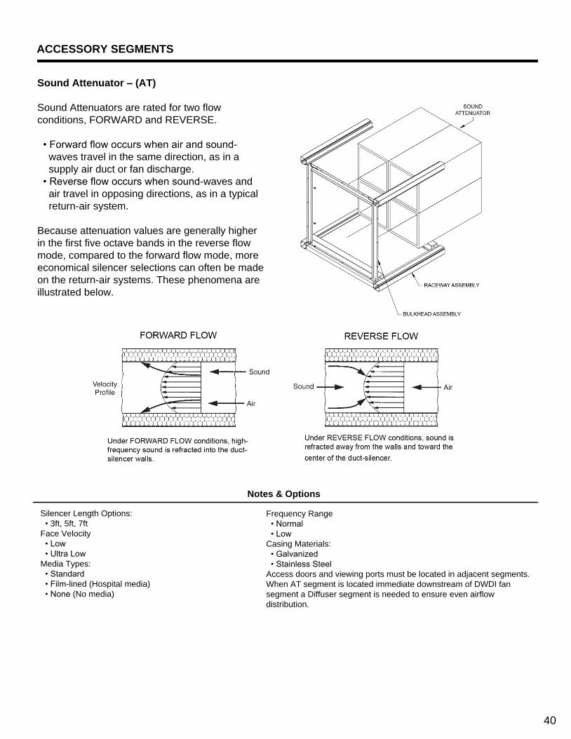
Sound Attenuator – (AT)
Sound Attenuators are rated for two flow
conditions, FORWARD and REVERSE.
• Forward flow occurs when air and sound-
waves travel in the same direction, as in a
supply air duct or fan discharge.
• Reverse flow occurs when sound-waves and
air travel in opposing directions, as in a typical
return-air system.
Because attenuation values are generally higher
in the first five octave bands in the reverse flow
mode, compared to the forward flow mode, more
economical silencer selections can often be made
on the return-air systems. These phenomena are
illustrated below.
Notes & Options
Silencer Length Options:
• 3ft, 5ft, 7ft
Face Velocity
• Low
• Ultra Low
Media Types:
• Standard
• Film-lined (Hospital media)
• None (No media)
Frequency Range
• Normal
• Low
Casing Materials:
• Galvanized
• Stainless Steel
Access doors and viewing ports must be located in adjacent segments.
When AT segment is located immediate downstream of DWDI fan
segment a Diffuser segment is needed to ensure even airflow
distribution.
40

Noise & Vibration
Any mechanical device is capable of generating noise and vibration for a variety of reasons. The air handler unit noise emanates simultaneously from three distinct sources: aerodynamic, mechanical, and electrical.
Noise generally applies to any problem in which the ears are the main sensor. Noise is made up of many different sound frequencies at various loudness levels. Noise when compared to vibration is similar in that they both have amplitude and frequency. Usually noise is a much lower amplitude and energy content which is measured in db referenced to Watts. Typically noise has a muchwider frequency range and a higher upper limit thanvibration (63Hz – 8KHz)
Vibration generally applies to any problem in whichthe hands or touching are the main sensor. Amplitude is large when there is a problem. It has much greater energy content with a smaller frequency range (3Hz – 500Hz)
Noise Considerations and Characteristics
Mechanical and electrical noise sources usually begin as vibration and are later transferred into airborne noise.
To avoid unsatisfactory noise levels, many factors should be considered at the design stage. Noise is generally considered low quality, unwanted sound. Characteristic words such as tone, pitch, steady, unsteady and intermittent help to define whether the source of the noise is aerodynamic, mechanical or electrical.
Vibration Considerations and Characteristics
Rotating devices, such as air handling units, all create vibration which can be transmitted to other parts of the structure. The magnitude of this vibration is subject to a number of things, the most significant of which is the
amount of unbalance of the rotating components. The frequency at which this occurs is the operating RPM of the components. There are many different sources of vibration. One of the most difficult tasks is the systematic identification of the vibration characteristic; amplitude, frequency, location or direction.
41
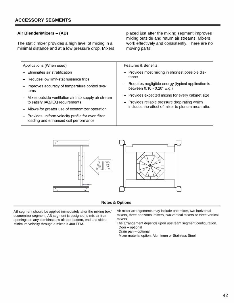
ACCESSORY SEGMENTS
Notes & Options
Air Blender/Mixers – (AB)
The static mixer provides a high level of mixing in a
minimal distance and at a low pressure drop. Mixers
placed just after the mixing segment improves
mixing outside and return air streams. Mixers
work effectively and consistently. There are no
moving parts.
AB segment should be applied immediately after the mixing box/
economizer segment. AB segment is designed to mix air from
openings on any combinations of: top, bottom, end and sides.
Minimum velocity through a mixer is 400 FPM.
Air mixer arrangements may include one mixer, two horizontal
mixers, three horizontal mixers, two vertical mixers or three vertical
mixers.
The arrangement depends upon upstream segment configuration.
Door – optional
Drain pan – optional
Mixer material option: Aluminum or Stainless Steel
42

Face & Bypass Damper Segments – (IB), (EB)
Internal Face & Bypass – (IB)
The IB Segment must be located immediately
upstream
of a reduced face coil.
• Designed to divert airflow around a coil.
When a full face coil is required downstream of the
reduced face coil, access segment(s) must be
included between the coils.
IB segment is used to control
• Humidity
• Low temperature flows across water coils
Notes & Options
Access doors and viewing ports must be located in adjacent
segments.
• An 18” access door is required immediately upstream of the IB
segment to access damper actuator and linkage.
Damper material option:
• Galvanized
• Aluminum
External Face & Bypass – (EB)
Each EB segment must be configured with a “bypass
air inlet” downstream in the configuration for
reintroducing the bypassed air to the unit. The EB
segment cannot exist without such a “bypass air inlet”
partner.
• The EB segment is available for indoor
application only
The external face and bypass damper is located
upstream of a full-face coil. External Bypass damper is
a balanced opposed blade face damper with
interconnecting linkage.
• Bypass duct is to be field supplied
Notes & Options
Damper material option:
• Galvanized
• Aluminum
Drain pan is optional
Door is optional
• It is designed to divert airflow through an external bypass duct.
• External Bypass segment assumes ‘top’ outlet.
43

ACCESSORY SEGMENTS
Turning Segments – (TN)
The purpose of the Turning Segment is to assist
air turning in a vertical direction.
A Turning Segment (TN) can only be located at
the end of a unit configuration.
Segment lengths are engineered for a variety of
tiered space saving configurations.
Notes & Options
TN segments are available for configuring in both top and bottom
tiers.
Drain pan is optional for bottom tier segments.
Access Door – Optional (both sides of the unit - Inward opening for
positive pressure)
Humidifier Segment – (HM)
Adding humidification for full winter comfort and productivity is just as important as air conditioning in the summer months. Temperature control must be combined with humidity control to maintain proper comfort parameters. ASHRAE 62 indicates that relative humidity is part of acceptable ventilation procedures & standard-of care
Revolution provides a standard steam injection distribution type humidifier with a short absorption manifold for use where short steam absorption distances are critical. • Steam is distributed evenly through the full length of the manifold. • The header size, number and spacing of distribution tubes shall be determined so that all steam is absorbed by the air before reaching the next component in the air stream depth.
Notes & Options
• Electric, gas and steam-to-steam generator types
• Optional auxiliary drain pan
• Optional access doors
• Optional controls
• The recommended location of the HM segment is
downstream of the HC segment but upstream of the CC
segment.
• The humidifier segment may be configured upstream of
RF, FF, and AF filter segments.
• Valve package shall be supplied and shipped loose.
Field Installation and wiring is required.
• The Humidifier Vendor humidifier selection software
shall size the valve package.
• Valves cannot be selected as an off-the-shelf item; each
valve has a specific plate/orifice specifically cut per order
specifications.
• Control valve actuation shall be electronic and shall be
compatible with either a 0-10V DC signal or a 4-20 mA
control signal.
• Factory mounted controls are not available in the Humidifier
segment. Any FMED device in a downstream segment
should be located at least the absorption distance away
from the humidifier manifold.
• Usual humidifier headers are located the same side as coil
headers.
• Optional stainless steel supports and liner
44
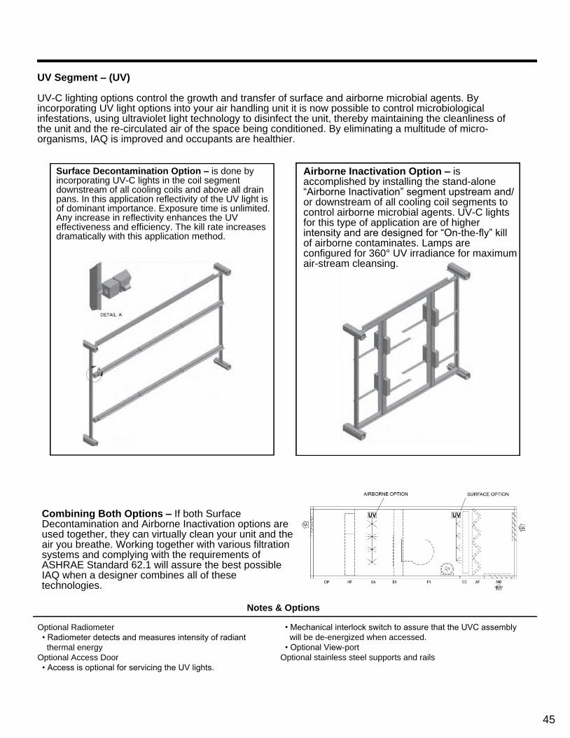
UV Segment – (UV)
UV-C lighting options control the growth and transfer of surface and airborne microbial agents. By incorporating UV light options into your air handling unit it is now possible to control microbiologicalinfestations, using ultraviolet light technology to disinfect the unit, thereby maintaining the cleanliness ofthe unit and the re-circulated air of the space being conditioned. By eliminating a multitude of micro-organisms, IAQ is improved and occupants are healthier.
Combining Both Options – If both Surface Decontamination and Airborne Inactivation options are used together, they can virtually clean your unit and the air you breathe. Working together with various filtration systems and complying with the requirements of ASHRAE Standard 62.1 will assure the best possible IAQ when a designer combines all of these technologies.
Notes & Options
Optional Radiometer
• Radiometer detects and measures intensity of radiant
thermal energy
Optional Access Door
• Access is optional for servicing the UV lights.
• Mechanical interlock switch to assure that the UVC assembly
will be de-energized when accessed.
• Optional View-port
Optional stainless steel supports and rails
Surface Decontamination Option – is done byincorporating UV-C lights in the coil segment downstream of all cooling coils and above all drain pans. In this application reflectivity of the UV light is of dominant importance. Exposure time is unlimited. Any increase in reflectivity enhances the UV effectiveness and efficiency. The kill rate increases dramatically with this application method.
Airborne Inactivation Option – is accomplished by installing the stand-alone “Airborne Inactivation” segment upstream and/or downstream of all cooling coil segments to control airborne microbial agents. UV-C lights for this type of application are of higher intensity and are designed for “On-the-fly” kill of airborne contaminates. Lamps are configured for 360° UV irradiance for maximum air-stream cleansing.
45

CONTROLS
Power Wiring Options
All motor wiring will be sized and installed based
upon National Electrical Code requirements. The
wire-ways will be categorized as follows:
• High Voltage – (120V and higher) is usually on
drive side of the product
• Low Voltage – (24V) is usually on opposite
drive side.
• All motor wiring will be installed neatly in
perpendicular and/or parallel planes with the
unit walls and floors.
Single Point Power (SPP) is defined as:
1. ALL electrical loads in a specific unit
configuration wired to a common point of
connection through the proper motor control
protection devices. This requires the
customer to bring only one source of power to
the unit.
2. Where motor controls (VFD, starter or wired
disconnect) are NOT selected, no motor
wiring shall be provided. Should 120V or 24V
elements be selected where motor controls
are not included, they shall require field
wiring.
3. Where multiple motor control devices are
selected, optionally, single point power
connections shall be provided. The field
power supply point shall be the supply fan
segment.
4. Where an external wired disconnect option is
selected for either supply or return/exhaust
fans (or both), single point wiring shall NOT
be available.
There are three different sizes of transformers
available; 150VA, 500VA, and 2000VA.
• The transformer being the device, used to
transform power from a primary voltage of 460
volts, 230 volts, or 575 volts, to a secondary
voltage level. An example of a secondary
voltage would be 120 volts.
A disconnect panel will be required anytime there are
(2) or (3) 3-phase loads that require a common factory
terminated wiring connection. A maximum of (3) 3-
phase loads are allowed for single point power option.
3-phase loads are as follows:
I. Supply Fan Motor Controller
II. Return / Exhaust Fan Motor Controller.
III. Gas Heater.
IV. Electric Heater.
V. Energy Wheel Motor Controller.
46

INDUSTRY FORMULAS
47