engineering graphics -2012
TRANSCRIPT

8/10/2019 Engineering Graphics -2012
http://slidepdf.com/reader/full/engineering-graphics-2012 1/29
Page 1 of 29
ENGINEERING GRAPHICS
CLASS - XII (046)
DESIGN OF THE QUESTION PAPER
Time : 3 Hrs Max. Marks : 70
The weightage of the distribution of marks over different contents of the question papershall be as follows:
A. WEIGHTAGE TO CONTENTS / SUBJECT UNITS
Unit Contents Marks
I Isometric Projection of Solids 25
II Machine Drawing
a) Machine Parts 15
b) Assembly / Disassembly 30
TOTAL 70
B. SCHEME OF OPTIONS
1. There will be no overall options.2. Internal Choices has been given in question of Machine Drawing.
C. WEIGHTAGE TO DIFFERENT LEVEL OF QUESTIONS
S.No. Estimated Difficult Level Percentage
1 Easy 15
2 Average 70
3 Difficult 15
# A weightage of 20% has been assigned to questions which testhigher order thinking skills.
2012

8/10/2019 Engineering Graphics -2012
http://slidepdf.com/reader/full/engineering-graphics-2012 2/29
Page 2 of 29
ENGINEERING GRAPHICS
CLASS – XII (046)
BLUE PRINT
Time : 3 Hrs Max. Marks : 70
1. UNIT I -- ISOMETRIC PROJECTION OF SOLIDS 24
S.No. Contents Weightage
a) Construction of Isometric Scale 4
b) Isometric Projection of a single vertical solid 7
c) Isometric Projection of combination of two solids 13
2. UNIT II -- MACHINE DRAWING 41
a) MACHINE PARTS 13
S.No. Contents Weightage
i) Drawing of machine parts by scale 1:1 usinginstruments
8
ii) Drawing of machine parts by sketching freehand
5
b) ASSEMBLY / DISASSEMBLY 28
S.No. Contents Weightage
i) Orthographic Views 22
ii) Title, Symbol of Projection, Scale, Dimension,
Line Work
6
3. SIMPLE MULTIPLE CHOICE QUESTIONS 5(based on the fundamentals of the above units.)

8/10/2019 Engineering Graphics -2012
http://slidepdf.com/reader/full/engineering-graphics-2012 3/29
Page 3 of 29
SAMPLE QUESTION PAPER – I
ENGINEERING GRAPHICS (046)
Time Allowed: 3 hours
Maximum Marks: 70
Note:(i) Attempt all the questions.
(ii) Use both sides of the drawing sheet, if necessary.
(iii) All dimensions are in millimetres.
(iv) Missing and mismatching dimensions, if any, may be suitably assumed.
(v) Follow the SP: 46, 2003 revised codes. (with First angle method of projection)
(vi) In no view of question 2, are hidden edges or lines required.
(vii) In question 4, hidden edges or lines are to be shown in views without section.
(viii) Number your answers according to questions.
Q1. Answer the following multiple choice questions. Print the correct choice on your drawingsheet. 5
(i) In isometric projection the three edges of an object are inclined to each other at(a) 60
o(b) 120
o (c) 100
o(d) 90
o
(ii) The angle between the flanks of a metric thread is(a) 60
o(b) 90
o (c) 75
o(d) 55
o
(iii) The number of cotters used in an assembly of sleeve and cotter joint are(a) One (b) Five (c) Four (d) Two
(iv) A square lamina in isometric projection appears as(a) Rhombus (b) Rectangle (c) Trapezium (d) Parallelogram
(v) Hidden / invisible edges are represented as(a) (b) (c) (d)
Q.2 (a) Construct an isometric scale of length 80mm. 4
(b) Draw the isometric projection to isometric scale of an inverted cone (diameter=70mm,height=75mm) with the circular face on top and its axis perpendicular to the H.P. Giveall the dimensions. 7
(c) A hexagonal pyramid of base edge 25mm and height 50mm, is placed centrally on the
top face of a square prism of base side 80mm and height 20mm. Two of the oppositeedges of the hexagonal base of the pyramid are perpendicular to the V.P. The commonaxes are perpendicular to the H.P. Draw the isometric projection of the combination toisometric scale and Give all the dimensions and indicate the direction of viewing. 13
Q.3 (a) Draw to scale 1:1, the standard profile of the metric thread (internal) with thepitch=50mm.Give standard dimensions. 8
OR

8/10/2019 Engineering Graphics -2012
http://slidepdf.com/reader/full/engineering-graphics-2012 4/29
Page 4 of 29
Draw to scale 1:1, the front view and side view of a tee headed bolt with diameterM25, keeping its axis parallel to both V.P and H.P. Give standard dimensions.
(b) Sketch free hand the front view and top view of a cheese head screw of size M20,keeping its axis vertical. Give all the standard dimensions. 5
ORSketch free hand the front view, top view and side view of a rectangular sunk taper keyfor a shaft of 60mm diameter. Give all the standard dimensions.
Q.4 Assemble the given V-Belt Pulley, Shaft and Rectangular Sunk Key as shown in Fig 1 anddraw the following views, to scale 1:1: 28
(a) Front View, upper half in section.(b) Side view looking from the right end.(c) Give 8 important dimensions, Title, Projection symbol and Scale.

8/10/2019 Engineering Graphics -2012
http://slidepdf.com/reader/full/engineering-graphics-2012 5/29
Page 5 of 29
OR
Dis-assemble the Bushed Bearing as shown in Fig 2, and draw the views of the followingparts:
(a) BODY
(i) Front View, left half in section.
(ii) Top View.
(b) BUSH
(i) Front View, right half in section.
(ii) Top View.
(c) Give 8 important dimensions, Title, Projection symbol and Scale.

8/10/2019 Engineering Graphics -2012
http://slidepdf.com/reader/full/engineering-graphics-2012 6/29
Page 6 of 29
SAMPLE QUESTION PAPER – I
VALUE POINTS
Q1 MULTIPLE CHOICE QUESTIONS
(i) b 1 (ii) a 1 (iii) d 1 (iv) a 1 (v) d 1
Q2 (a) ISOMETRIC SCALE : FIG – 1.1 4
(i) Drawing 45o inclined
lines showing true lengths 1
(ii) Projections on 30o
inclined line showing isometric length with one 1mm
subdivisions 2
(iii) Writing titles, sub titles and angles 1
FIG – 1.1 FIG – 1.2
(b) ISOMETRIC PROJECTION OF A CONE : FIG – 1.2 7
(i) Drawing elliptical curve 3
(ii) Drawing two generators 2
(iii) Indicating the axis 1
(iv) Three dimensions 1

8/10/2019 Engineering Graphics -2012
http://slidepdf.com/reader/full/engineering-graphics-2012 7/29
Page 7 of 29
(c) ISOMETRIC PROJECTION OF COMBINATION OF SOLIDS : FIG – 1.3 13
(i) Helping figures 1
(ii) Drawing isometric squares 2
(iii) Drawing vertical lines indicating the faces 2
(iv) Drawing hexagonal base of pyramid 2
(v) Drawing slant edges 2
(vi) Common axis, dimensioning, direction of viewing 4
FIG – 1.3

8/10/2019 Engineering Graphics -2012
http://slidepdf.com/reader/full/engineering-graphics-2012 8/29
Page 8 of 29
Q3 (a) METRIC THREAD (INTERNAL) : FIG – 1.4 8
(i) Distance equal to pitch, and angles of 60o
2
(ii) Flat edges and curves for threads 2
(iii) Side edges / flanks 2
(iv) Dimensions 2
SAMPLE QUESTION PAPER – II
FIG – 1.4
OR
FIG – 1.5

8/10/2019 Engineering Graphics -2012
http://slidepdf.com/reader/full/engineering-graphics-2012 9/29
Page 9 of 29
TEE BOLT : FIG – 1.5 8
Front View
(i) Cylindrical shank, square neck and centre line 21 / 2
(ii) Head of bolt 1
Side View
(i) Two circles 11 / 2
(ii) Square neck and rest of the portion 11 / 2
Dimensions 11 / 2
(b) CHEESE HEAD SCREW : FIG – 1.6 5
(i) Sketching head with threaded shank 21 / 2
(ii) Sketching conventional top view 1
(iii) Writing title, standard values and axis 11 / 2
FIG – 1.6 FIG – 1.7
OR
RECTANGULAR SUNK TAPER KEY : FIG – 1.7 5
(i) Sketching front view 11 / 2
(ii) Sketching top view and side view 2
(iii)Writing title and standard values 11 / 2

8/10/2019 Engineering Graphics -2012
http://slidepdf.com/reader/full/engineering-graphics-2012 10/29
Page 10 of 29
Q 4 ASSEMBLY OF V-BELT PULLEY: FIG – 1.8 28
(a) FRONT VIEW, UPPER HALF IN SECTION
Drawing upper half in section with V groove. 8
Drawing Lower half without section. 5
(b) SIDE VIEW, VIEWING FROM THE RIGHT HAND SIDE
Drawing five circles. 5
Drawing other details. 4
(c) OTHERS
Important Dimensions. 2
Titles, Symbol of Projection and Scale. 4
FIG – 1.8

8/10/2019 Engineering Graphics -2012
http://slidepdf.com/reader/full/engineering-graphics-2012 11/29
Page 11 of 29
OR
DIS-ASSEMBLY OF BUSHED BEARING: FIG – 1.9 28
(a) BODY
(i) Front View.
Drawing left half in section. 5
Drawing right half without section. 3
(ii) Top View. 7
(b) BUSH
(i) Front View, right half in section. 4
(ii) Top View. 3
(c) OTHERS
Important Dimensions. 2
Titles, Symbol of Projection and Scale. 4
FIG – 1.9

8/10/2019 Engineering Graphics -2012
http://slidepdf.com/reader/full/engineering-graphics-2012 12/29
Page 12 of 29
SAMPLE QUESTION PAPER – II
ENGINEERING GRAPHICS (046)
Time Allowed: 3 hours Maximum Marks: 70
Note:(i) Attempt all the questions.
(ii) Use both sides of the drawing sheet, if necessary.
(iii) All dimensions are in millimetres.
(iv) Missing and mismatching dimensions, if any, may be suitably assumed.
(v) Follow the SP: 46 2003 revised codes. (with First angle method of projection)
(vi) In no view of question 2, are hidden edges or lines required.
(vii) In question 4, hidden edges or lines are to be shown in views without section.
(viii) Number your answers according to questions.
Q1. Answer the following multiple choice questions. Print the correct choice on your drawingsheet. 5
(i) Which one among the following represents a permanent fastener
a) Nut b) Rivet c) Screw d) Bolt
(ii) The convexity provided on the rim of the solid web cast iron pulley is called
a) Bending b) Curving c) Crowning d) Riveting
(iii) Section lines are generally inclined with the base, at an angle of
a) 30o b)45
o c)60
o d)90
o
(iv) The isometric view of a sphere is alwaysa) a circle b) an ellipse c) a Parabola d) a Semicircle
(v) In isometric projection, the four center method is used to construct
a) an ellipse b) a square c) a triangle d) a rectangle
Q.2 (a) Construct an isometric scale of 80mm long. 4
(b) Construct the isometric projection to isometric scale of the frustum of a regular squarepyramid, kept in the inverted position, with base edge 30mm, top edge 50mm andheight 80mm, resting on the H.P., with its axis vertical. Two of the opposite paralleledges of the square face are perpendicular to the V.P. Draw the axis and indicate the
direction of viewing. 7
(c) A hemisphere of diameter 60mm is placed centrally with its circular face upwards, on apentagonal prism of base edge 50mm and height 20mm. One of the base edges of thepentagonal prism is perpendicular to the V.P. The common axes are perpendicular tothe H.P. Draw the isometric projection of the combination of solids and give all thedimensions. Indicate the direction of viewing. 13

8/10/2019 Engineering Graphics -2012
http://slidepdf.com/reader/full/engineering-graphics-2012 13/29
Page 13 of 29
Q3. (a) Draw to scale 1:1, the front view and top view of a hexagonal nut, the bolt diameteris given as 20 mm. The axis of the nut is vertical. Give the standard dimensions. 8
OR
Draw to scale 1:1, the front view and side view of a square headed bolt of diameter
20mm, keeping its axis parallel to both V.P. & H.P. Give all the standard dimensions.
(b) Sketch free hand the front view and top view of a snap head rivet of diameter 30mm,taking its axis vertical. Give all the standard dimensions. 5
OR
Sketch free hand the front view and side view of a collar stud of size M20, keeping itsaxis perpendicular to the H.P. Give all the standard dimensions.
Q.4 Assemble the Protected Flange Coupling, Shaft with Nut-Bolt as shown in Fig 1 and drawthe following views: 28
(a) Front View, upper half in section.(b) Side view looking from the Left end.
(c) Give 8 important dimensions, Title, Projection symbol and Scale.
OR
8/10/2019 Engineering Graphics -2012
http://slidepdf.com/reader/full/engineering-graphics-2012 14/29
Page 14 of 29
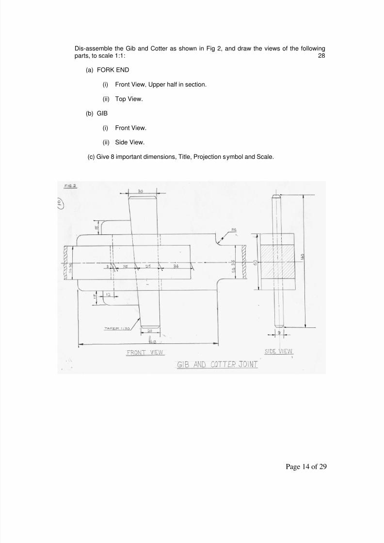
Dis-assemble the Gib and Cotter as shown in Fig 2, and draw the views of the followingparts, to scale 1:1: 28
(a) FORK END
(i) Front View, Upper half in section.
(ii) Top View.
(b) GIB
(i) Front View.
(ii) Side View.
(c) Give 8 important dimensions, Title, Projection symbol and Scale.

8/10/2019 Engineering Graphics -2012
http://slidepdf.com/reader/full/engineering-graphics-2012 15/29
Page 15 of 29
SAMPLE QUESTION PAPER – II
VALUE POINTS
Q1 MULTIPLE CHOICE QUESTIONS
(i) b 1 (ii) c 1 (iii) b 1 (iv) a 1 (v) a 1
Q2 (a) ISOMETRIC SCALE : FIG – 2.1 4
(i) Drawing 45o inclined
lines showing true lengths 1
(ii) Projections on 30o
inclined line showing isometric length with one 1mm
subdivisions 2
(iii) Writing titles, sub titles and angles 1
FIG – 2.1
FIG – 2.2
(b) ISOMETRIC PROJECTION OF THE FRUSTUM OF AN INVERTED SQUARE PYRAMID:FIG – 2.2 7
(i) Drawing Isometric squares 3
(ii) Drawing slant edges 2
(iii) Axis, dimensioning, direction of viewing 2

8/10/2019 Engineering Graphics -2012
http://slidepdf.com/reader/full/engineering-graphics-2012 16/29
Page 16 of 29
(C) ISOMETRIC PROJECTION OF COMBINATION OF SOLIDS: FIG – 2.3 13
(i) Helping views 1
(ii) Drawing Isometric hemisphere 4
(iii) Drawing isometric pentagon with vertical lines 4
(iv) Common axis, dimensioning, direction of viewing 4
FIG – 2.3

8/10/2019 Engineering Graphics -2012
http://slidepdf.com/reader/full/engineering-graphics-2012 17/29
Page 17 of 29
Q3 (a) HEXAGONAL NUT : FIG – 2.4 8
(i) Drawing front view with details 3
(ii) Drawing top view with details 3
(iii) Dimensions and titles 2
FIG – 2.4
OR
SQUARE HEADED BOLT : FIG – 2.5 8
(i) Drawing front view with details 3
(ii) Drawing side view with details 3
(iii) Titles and standard dimensions 2
FIG – 2.5

8/10/2019 Engineering Graphics -2012
http://slidepdf.com/reader/full/engineering-graphics-2012 18/29
Page 18 of 29
Q3 (b) SNAP HEAD RIVET : FIG – 2.6 5
(i) Sketching the front view 2
(ii) Sketching the top view 1
(iii) Writing titles, standard values and axis 2
FIG – 2.6 FIG – 2.7
OR
COLLAR STUD : FIG – 2.7 5
(i) Sketching stud with collar 2
(ii) Sketching the top view 1
(iii) Writing titles, standard values and axis 2
Q4 ASSEMBLY OF PROTECTED FLANGE COUPLING : FIG – 2.8 28
(a) FRONT VIEW

8/10/2019 Engineering Graphics -2012
http://slidepdf.com/reader/full/engineering-graphics-2012 19/29
Page 19 of 29
Drawing upper half in section. 9 Drawing Lower half without section. 4
(b) SIDE VIEW Drawing six circles. 5
Drawing other details. 4
(c) OTHERS Important Dimensions. 2Titles, Symbol of Projection and Scale. 4
FIG – 2.8
OR
DIS-ASSEMBLY OF GIB AND COTTER JOINT : FIG – 2.9 28
(a) FORK END
(i) Front View
Drawing upper half in section 5Drawing lower half without section. 3
(ii) Top View. 6

8/10/2019 Engineering Graphics -2012
http://slidepdf.com/reader/full/engineering-graphics-2012 20/29
Page 20 of 29
(b) GIB
(i) Front View, right half in section. 5
(ii) Top View. 3
(c) OTHERS
Important Dimensions. 2Titles, Symbol of Projection and Scale. 4
FIG – 2.9

8/10/2019 Engineering Graphics -2012
http://slidepdf.com/reader/full/engineering-graphics-2012 21/29
Page 21 of 29
SAMPLE QUESTION PAPER – III
ENGINEERING GRAPHICS (046)
Time Allowed: 3 hours Maximum Marks: 70
Note:(i) Attempt all the questions.
(ii) Use both sides of the drawing sheet, if necessary.
(iii) All dimensions are in millimetres.
(iv) Missing and mismatching dimensions, if any, may be suitably assumed.
(v) Follow the SP: 46 2003 revised codes. (with First angle method of projection)
(vi) In no view of question 2, are hidden edges or lines required.
(vii) In question 4, hidden edges or lines are to be shown in views without section.
(viii) Number your answers according to questions.
Q1. Answer the following multiple choice questions. Print the correct choice on your drawingsheet. 5(i) With respect to the elevation and plan given below, name the solid
(a) Cone
(b) hexagonal prism
(c) cylinder
(d) hexagonal pyramid
(ii) A footstep bearing is aa) journal bearing b) thrust bearing c) pivot bearing d) pedestal bearing
(iii) The angle between the flanks of B.S.W. thread isa) 60
o b) 65
o c) 55
o d)75
o
(iv) Top view is projected on thea) Vertical Plane b) Corner Plane c) Side Plane d) Horizontal Plane
(v) With respect to the front view and top view given below, name the solid
(a) Cone
(b) Cylinder(c) Cube
(d) Frustum
Q.2 (a) Construct an isometric scale of length 70mm. 4

8/10/2019 Engineering Graphics -2012
http://slidepdf.com/reader/full/engineering-graphics-2012 22/29
Page 22 of 29
(b) Construct the isometric projection to isometric scale, of the frustum of a regularpentagonal pyramid of base edge 50mm and top edge 30mm, with its pentagonal endresting on the H.P. The height of the solid is 70 mm with its axis perpendicular to theH.P. One of the base edge, which is nearer the observer is parallel to the V.P. Draw theaxis and indicate the direction of viewing. 7
(c) A cylinder of diameter 40mm and height 50mm is placed centrally on the top surface ofa circular disc of diameter 60mm and height 20mm. The common axes areperpendicular to the H.P. Draw the isometric projection of the solids to isometricscale. Give all dimensions. 13
Q.3 (a) Draw to scale 1:1 the standard profile of a square thread and a knuckle thread, takingthe enlarged pitch as 40mm. Give all the standard dimensions. 8
OR
Draw to scale 1:1, the sectional front view and top view of a single riveted lap joint forthe plates of thickness 25mm. Give all the standard dimensions.
(b) Sketch free hand the front view and top view of a grub screw of diameter 25mm,keeping its axis vertical. Give all the standard dimensions. 5
OR
Sketch free hand the front view and side view of a plain stud of size M20, keeping itsaxis parallel to both V.P. & H.P. Give all the standard dimensions.
Q.4 Assemble the given parts of a Plummer Block as shown in Fig 1 and draw, to scale 1:1; 28
(a) Front View, left half in section.
(b) Give 8 important dimensions, Title, Projection symbol and Scale.
OR
Dis-assemble the Sleeve and Cotter Joint as shown in Fig 2, and draw the views of thefollowing parts: 28
(a) SLEEVE
(i) Front View, Top half in section.
(ii) Side View, viewing from left.
(b) COTTER
(i) Front View.
(ii) Top View.
(c) Give 8 important dimensions, Title, Projection symbol and Scale.

8/10/2019 Engineering Graphics -2012
http://slidepdf.com/reader/full/engineering-graphics-2012 23/29
Page 23 of 29

8/10/2019 Engineering Graphics -2012
http://slidepdf.com/reader/full/engineering-graphics-2012 24/29
Page 24 of 29
SAMPLE QUESTION PAPER – III
VALUE POINTS
Q1 MULTIPLE CHOICE QUESTIONS
(i) c 1 (ii) c 1 (iii) c 1 (iv) d 1 (v) a 1
Q2 (a) ISOMETRIC SCALE : FIG – 3.1 4
(i) Drawing 45o inclined
lines showing true lengths 1
(ii) Projections on 30o
inclined line showing isometric length with one 1mm
subdivisions 2
(iii) Writing titles, sub titles and angles 1
FIG – 3.1
(b) ISOMETRIC PROJECTION OF FRUSTUM OF PENTAGONAL PYRAMID : FIG – 3.2 7
(i) Helping view 1
(ii) Drawing Isometric pentagons 2
(iii) Drawing slant edges 2
(iv) Axis, dimensioning, direction of viewing 2
(c) ISOMETRIC PROJECTION OF COMBINATION OF SOLIDS : FIG – 3.3 13
(i) Drawing four elliptical curves 6
(ii) Drawing generators 4
(iii) Common axis, dimensioning 3

8/10/2019 Engineering Graphics -2012
http://slidepdf.com/reader/full/engineering-graphics-2012 25/29
Page 25 of 29
FIG – 3.3
FIG – 3.2
Q3 (a) SQUARE THREAD AND KNUCKLE THREAD : FIG – 3.4 8
(i) Drawing the square profile 3
(ii) Drawing the knuckle profile 3
(iii) Dimensions and titles 2

8/10/2019 Engineering Graphics -2012
http://slidepdf.com/reader/full/engineering-graphics-2012 26/29
Page 26 of 29
OR
SINGLE RIVETED LAP JOINT : FIG – 3.5 8
(i) Front view with details 3
(ii) Top view with details 3
(iii) Dimensions and titles 2
FIG – 3.5
Q3 (b) GRUB SCREW : FIG – 3.6 5
(i) Front view with its axis 2
(ii) Top view 2
(iii) Dimensions 1

8/10/2019 Engineering Graphics -2012
http://slidepdf.com/reader/full/engineering-graphics-2012 27/29
Page 27 of 29
FIG – 3.6
OR
PLAIN STUD : FIG – 3.7 5
(i) Sketching the front view 2
(ii) Sketching the side view 1
(iii) Writing the titles and standard values 2
FIG – 3.7

8/10/2019 Engineering Graphics -2012
http://slidepdf.com/reader/full/engineering-graphics-2012 28/29
Page 28 of 29
Q4 ASSEMBLY OF PLUMMER BLOCK : FIG – 3.8 28
(a) FRONT VIEW
Drawing left half in section 12
Drawing right half without section 10
(b) OTHERS
Important Dimensions 2
Titles, Symbol of Projection and Scale 4
FIG – 3.8
OR

8/10/2019 Engineering Graphics -2012
http://slidepdf.com/reader/full/engineering-graphics-2012 29/29
DIS-ASSEMBLY OF SLEEVE AND COTTER JOINT : FIG – 3.9 28
(a) SLEEVE
(i) Front View, upper half in section.
Drawing upper half in section. 6
Drawing right half without section. 3
(ii) Side View 7
(b) COTTER
(i) Front View 3
(ii) Top View 3
(c) OTHERS
Important Dimensions 2
Titles, Symbol of Projection and Scale 4
FIG – 3.9