engineering geology report harley slide green springs highway or 66 highway no. 21 m.p ......
TRANSCRIPT

ENGINEERING GEOLOGY REPORT Harley Slide
Green Springs Highway OR 66 Highway No. 21 M.P. 11.8-12.0
Jackson County
Key 17535 EA PE002600/000
June 16, 2017
By: Jason Garwood, C.E.G.
REGION 3 TECH CENTER, GEO/ENVIRONMENTAL UNIT OREGON DEPARTMENT OF TRANSPORTATION

i
TABLE OF CONTENTS
1.0 INTRODUCTION 1 1.1 Project Location .............................................................................................................................. 1 1.2 Project Description ......................................................................................................................... 3 1.3 Geologic Setting ............................................................................................................................. 3 1.4 Seismicity ....................................................................................................................................... 4
2.0 SUBSURFACE INVESTIGATION 5
2.1 Drilling and Sampling ..................................................................................................................... 5 2.2 Material Units .................................................................................................................................. 5
2.2.1 Fill (Unit 1) ............................................................................................................................... 6 2.2.2 Fill (Unit 2) ............................................................................................................................... 6
2.2.3 Slide Debris (Unit 3) ................................................................................................................ 6 2.2.4 Roxy Formation - Decomposed TUFF (Unit 4) ....................................................................... 6 2.2.5 Roxy Formation - Decomposed BASALT/VOLCANICS (Unit 5) ............................................ 7 2.2.6 Roxy Formation - BASALT/VOLCANICS (Unit 6) ................................................................... 7 2.2.7 Roxy Formation - BASALT (Unit 7) ......................................................................................... 7
2.3 Laboratory Testing ......................................................................................................................... 7 2.4 Instrumentation ............................................................................................................................... 7
3.0 DISCUSSION AND CONCLUSION 9
4.0 LIMITATIONS 10
5.0 REFERENCES 11
6.0 SIGNATURE PAGE 12 FIGURES Figure 1 - Site Location Map 3 Figure 2 - Geologic Map 3 TABLES Table 1 - Drillhole Summary 5 Table 2 - Instrumentation Summary 8
APPENDICES Appendix A - Data Sheets GA01, GA02, GA03 and GA04 Appendix B - Drillhole Logs Appendix C - Core Photographs Appendix D - Laboratory Testing Data Appendix E - Groundwater Data Appendix F - Slope Inclinometer Data
Geology Report (Final) Highway 66 MP 11.8-12.0, Harley Slide June 16, 2017 Page 1 of 12
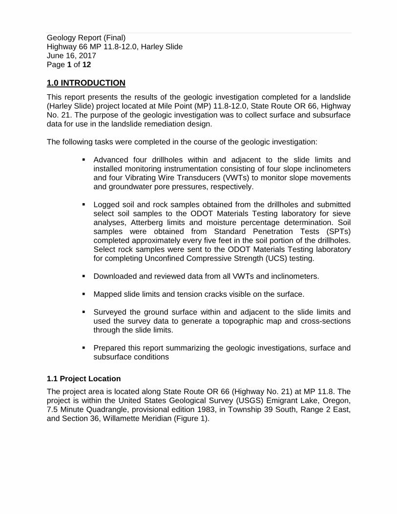
1.0 INTRODUCTION This report presents the results of the geologic investigation completed for a landslide (Harley Slide) project located at Mile Point (MP) 11.8-12.0, State Route OR 66, Highway No. 21. The purpose of the geologic investigation was to collect surface and subsurface data for use in the landslide remediation design. The following tasks were completed in the course of the geologic investigation:
Advanced four drillholes within and adjacent to the slide limits and installed monitoring instrumentation consisting of four slope inclinometers and four Vibrating Wire Transducers (VWTs) to monitor slope movements and groundwater pore pressures, respectively.
Logged soil and rock samples obtained from the drillholes and submitted
select soil samples to the ODOT Materials Testing laboratory for sieve analyses, Atterberg limits and moisture percentage determination. Soil samples were obtained from Standard Penetration Tests (SPTs) completed approximately every five feet in the soil portion of the drillholes. Select rock samples were sent to the ODOT Materials Testing laboratory for completing Unconfined Compressive Strength (UCS) testing.
Downloaded and reviewed data from all VWTs and inclinometers.
Mapped slide limits and tension cracks visible on the surface.
Surveyed the ground surface within and adjacent to the slide limits and
used the survey data to generate a topographic map and cross-sections through the slide limits.
Prepared this report summarizing the geologic investigations, surface and
subsurface conditions 1.1 Project Location The project area is located along State Route OR 66 (Highway No. 21) at MP 11.8. The project is within the United States Geological Survey (USGS) Emigrant Lake, Oregon, 7.5 Minute Quadrangle, provisional edition 1983, in Township 39 South, Range 2 East, and Section 36, Willamette Meridian (Figure 1).

Geology Report (Final) Highway 66 MP 11.8-12.0, Harley Slide June 16, 2017 Page 2 of 12
Figure 1: Site Location Map
I-5
To Ashland, OR
Project Location
OR66
To Siskiyou Summit

Geology Report (Final) Highway 66 MP 11.8-12.0, Harley Slide June 16, 2017 Page 3 of 12
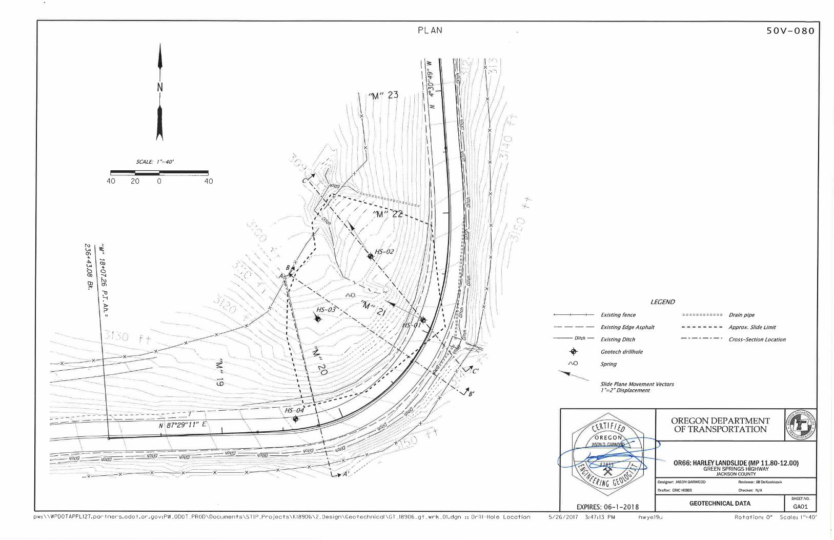
1.2 Project Description The slide has impacted both travel lanes and extends between approximately Station (Sta.) along the “M” Line of 19+70 and Sta. 21+90 in the southbound lane of OR 66 (Sheet GA01 in Appendix A). The slide extends between an elevation of approximately 3,133 feet at the headscarp down to an elevation of approximately 3,090 feet at the toe (Sheets GA01 and GA02 in Appendix A). This slide location sits within a natural draw in steep terrain, and according to ODOT Maintenance personnel, the road alignment in this location has had stability issues each spring season for approximately the last ten years. ODOT Maintenance personnel have been patching the asphalt each year to keep the roadway operational. A drain and drain pipe were placed above the slide to divert water from the drainage away from the slide. The surface evaluation located a seep between drillholes HS-02 and HS-03. The drilling program addressed the soil and rock types and depths, the slide plane geometry and groundwater conditions. 1.3 Geologic Setting Located southeast of Ashland about 7.5 miles, the slide is mapped within the Western Cascades geologic province at an elevation of approximately 3,130 feet. The project is within the Eocene/Oligocene (25-38my) aged, Roxy (Torb) Formation. The bedrock mapped in this area is a mix of Volcanic Flow rocks of Basalt and Andesite (Smith and Roe 2015). The site has been mapped within a Landslide Deposit as shown in Figure 2 (Wiley, McClaughry and D’Allura 2011).

Geology Report (Final) Highway 66 MP 11.8-12.0, Harley Slide June 16, 2017 Page 4 of 12
Figure 2 – Geologic Map of the project area; modified after original (Wiley, McClaughry and D’Allura 2011). 1.4 Seismicity The Geologic database and generalized geologic map of Bear Creek Valley, Jackson County, Oregon by Thomas Wiley has located faults mapped throughout the general area of the project. USGS fault maps show the Sky Lakes fault zone to the NE about 26 miles and the Klamath graben fault zone to the east approximately 31 miles. The Cedar Mountain fault zone is to the SE about 23 miles. The age and activity of these normal faults are considered Quaternary in the geologic interpretation. The Cascadia Subduction Zone is located approximately 67 miles west of the project site (Peterson, Kulm and Gray, 1986). USGS, National Seismic Hazard Mapping Project, 2008, calculates a peak bedrock acceleration of 0.13g and 0.19g for the 500-year and 1,000-year return-period earthquakes respectively, from all seismic sources in the region.
Roxy Formation
Payne Cliffs Formation
Landslide
Project Area
N
OR66

Geology Report (Final) Highway 66 MP 11.8-12.0, Harley Slide June 16, 2017 Page 5 of 12
2.0 SUBSURFACE INVESTIGATION
2.1 Drilling and Sampling The subsurface investigation was conducted during July 2012 and directed by personnel from the Region 3 Geology Unit. The drillholes were drilled by HazTech Drilling, Inc. of Meridian, Idaho. A total of four vertical drillholes (HS-01, HS-02, HS-03 and HS-04) were advanced in accordance with ASTM standards (Table 1). A truck-mounted drill was utilized and equipped with an automatic-trip hammer and diamond coring capabilities. The drillholes depths ranged from 35.0 feet below ground surface (bgs) in HS-01 to 51.0 feet bgs in HS-03. The total footage drilled for the project was 172 feet. The drillholes were advanced with a combination of using Hollow Stem Auger (HSA) and HQ3 Wireline core in the soil and rock materials, respectively. A total of 42 SPTs were collected. SPTs were collected on approximate five-foot spacings. The samples collected from the SPTs were logged in general accordance with ODOT Soil and Rock classification methods (ODOT 1987). The blow counts were recorded on the drillhole logs (Appendix B). A total of 65.9 feet of core was drilled in the four drillholes. Core runs were generally five feet-long, preserved in cardboard core boxes and photographed (Appendix C). Slope inclinometers and VWTs were installed in each hole. The placing of the VWTs was determined by the depth of the water table encountered, and the bedrock contact depth. Table 1 provides a summary of the drillhole location, depth and instrumentation installations.
Table 1
Drillhole Summary
Drillhole Number
Northing (feet)
Easting (feet)
Elevation (feet)
Drillhole Depth (feet)
Instrumentation Depth (feet)
VWT Inclinometer HS-01 62,082.6 45,981.3 3,132.5 35.0 19.0 35.0 HS-02 62,134.3 45,938.3 3,106.9 41.0 19.0 41.0 HS-03 62,083.3 45,895.5 3,112.5 51.0 19.0 51.0 HS-04 62,002.1 45,877.7 3,141.5 45.0 37.0 45.0
2.2 Material Units Seven material units were interpreted from the subsurface investigation: Fill (Units 1 and 2), Landslide Debris (Unit 3) and four sub-units of the Roxy Formation (Units 4, 5, 6 and 7), consisting of decomposed tuff, decomposed basalt, weathered basalt and fresh basalt, respectively. A detailed description of the material units can be found on the attached drillhole logs in Appendix B.

Geology Report (Final) Highway 66 MP 11.8-12.0, Harley Slide June 16, 2017 Page 6 of 12
2.2.1 Fill (Unit 1) This material was found in drillholes HS-01, and HS-04. These two drillholes were restricted to the OR 66 roadway prism. This material overlies the slide debris (Unit 3). A total of 15.5 feet of this material was encountered during the drilling. The elevation of the basal contact of this unit ranges between 3,122.0 and 3,134.5 feet above mean sea level (MSL) in drillholes HS-01 and HS-04, respectively. The unit has an average thickness of 9.5 feet. A total of five SPTs were collected in this material with uncorrected N Values ranging between 11 and 33 with an average of 16 blows-per-foot. This fill is composed of Sandy GRAVEL with trace silt, GW, to CLAY with trace sand, CH, to Clayey SAND with some gravel, SC. Color ranges from black, dark gray to gray and brown to dark brown. The plasticity ranges from nonplastic to high-plasticity. The soil is dry to damp, is medium dense to dense and medium stiff to stiff. The sand is fine to coarse-grained and the angular gravel is fine to coarse-grained. 2.2.2 Fill (Unit 2) This material was found in drillhole HS-03. This material was produced by the construction of the access road for the two drillholes (HS-02 and HS-03) below OR 66. This material is approximately three feet-thick. A total of one SPT was collected in this material with an uncorrected N Value of three blows-per-foot. This fill is composed of CLAY with trace sand, CH, is brown to black in color, has high-plasticity, and is moist and soft. 2.2.3 Slide Debris (Unit 3) This material was found in drillholes HS-01, HS-02 and HS-03. This material overlies the basalt and tuff of the Roxy Formation. The basal contact elevations were 3,091.3, 3,095.4 and 3,112.7 feet above MSL in drillholes HS-02, HS-03 and HS-04, respectively. A total of 14 SPTs were collected in this unit with uncorrected N Values ranging between four and 11 with an average of eight blows-per-foot. The slide debris ranges from CLAY with some sand, trace gravel, CH, to Sandy CLAY with trace to some gravel, CH, to CLAY with trace to some sand, CH. The color of this material ranges from dark gray, black, brown, gray-brown to orange-brown. The plasticity is high with the moisture content ranging from damp to wet. The consistency is soft to stiff with fine to coarse-grained sand.
2.2.4 Roxy Formation - Decomposed TUFF (Unit 4) This material was encountered in drillholes HS-03 and HS-04. This material overlies the basalt of the Roxy Formation. The basal contact elevations ranged between 3,083.5 and 3,112.5 feet above MSL in drillholes HS-03 and HS-04, respectively. The unit has

Geology Report (Final) Highway 66 MP 11.8-12.0, Harley Slide June 16, 2017 Page 7 of 12
an average thickness of 17 feet. A total of 14 SPTs were collected in this material with uncorrected N Values ranging between 12 and 35 with an average of 22 blows-per-foot. The decomposed tuff ranges from CLAY with trace to some sand, CH, to Sandy CLAY, CH, to Clayey SAND with some gravel, SC. Colors range from light brown, brown, gray-brown, orange-brown, red-brown, to white. The plasticity is high with the moisture content ranging from damp to moist. The consistency is very stiff to hard and medium dense with fine to coarse-grained sand and fine-grained angular gravel. 2.2.5 Roxy Formation - Decomposed BASALT/VOLCANICS (Unit 5) This material was found in drillholes HS-02, HS-03 and HS-04. This material makes up the uppermost portion of the bedrock and has an average thickness of 4.3 feet. The basal contact elevations were 3,077.4, 3,085.9 and 3,111.0 feet above MSL in drillholes HS-03, HS-02 and HS-04, respectively. A total of three SPTs were collected in this material with uncorrected N Values ranging between 41 and 64 with an average of 51 (refusal). The decomposed basalt remolds to a Clayey SAND with some gravel, SC, to SAND with some clay trace silt and gravel, SP-SM, to SP-SC. Color ranges from light brown, brown, dark brown, orange-brown, red-brown, and gray. Plasticity ranges from nonplastic to medium-plasticity, and the moisture content ranges from damp to wet. Relative density is dense to very dense. The sand is fine to coarse-grained. 2.2.6 Roxy Formation - Weathered BASALT/VOLCANICS (Unit 6) This material was found in drillholes HS-02 and HS-04. This material overlies the fresh basalt of the Roxy Formation and has an average thickness of 8.3 feet. The basal contact elevations range between 3,075.4 and 3,105.0 feet above MSL in drillholes HS-02 and HS-04, respectively. There were no SPTs collected in this unit. The weathered basalt is orange-brown to light gray, predominantly decomposed to slightly weathered, very soft to hard and very close to close jointed. 2.2.7 Roxy Formation - BASALT (Unit 7) This material was found in all the drillholes (HS-01, HS-02, HS-03 and HS-04). The average drilling thickness was 12.3 feet. The basalt is light gray to gray, fresh, medium hard to very hard and is close to wide jointed. 2.3 Laboratory Testing Selected soil and rock samples were tested for engineering properties at the ODOT Materials Laboratory located in Salem, Oregon. Laboratory tests included: Atterberg

Geology Report (Final) Highway 66 MP 11.8-12.0, Harley Slide June 16, 2017 Page 8 of 12
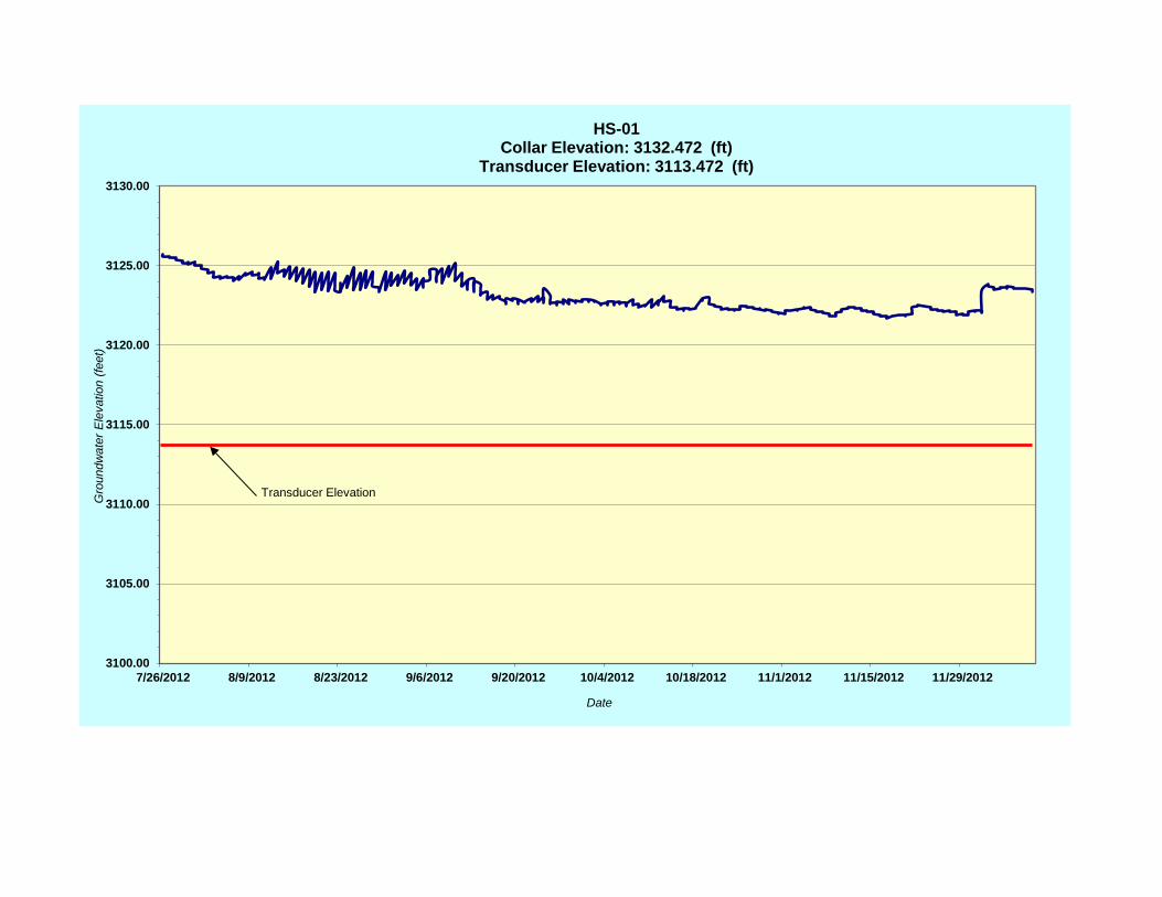
limits, natural moisture content, and gradation of the materials and organics. Selected rock core was tested for unconfined compressive strength (UCS) at the ODOT Materials Lab. Laboratory testing results are included on the drillhole logs in Appendix B and summarized in Appendix D. 2.4 Instrumentation A total of four Slope inclinometers and four VWTs were installed to monitor subsurface slope displacement and groundwater levels, respectively. The VWT installed in drillhole HS-01 was installed within the slide debris (Unit 3) immediately above the slide plane. The VWT installed in HS-02 was installed beneath the slide plane in the decomposed BASALT (Unit 5). The VWT installed in drillhole HS-03 was installed in the upper portion of the decomposed TUFF (Unit 4). The VWT installed in drillhole HS-04 was installed in the uppermost portion of the BASALT (Unit 7). Table 2 provides a summary of the groundwater elevation data with the groundwater plots provided in Appendix E.
Table 2 Instrumentation Summary
Drillhole Number VWT S/N
Installation Elevation
(feet) Installation
Date
Groundwater Elevation (feet) Slide Plane
Elevation (feet) Minimum Maximum
HS-01 1122987 3,113.5 7/11/2012 3,121.7 3,125.8 3,113.6 HS-02 1122993 3,087.9 7/12/2012 3,088.4 3,105.9 3,092.9 HS-03 1122984 3,093.5 7/13/2012 3,103.5 3,112.9 3,097.4 HS-04 1122989 3,104.5 7/10/2012 3,105.0 3,115.4 N/A
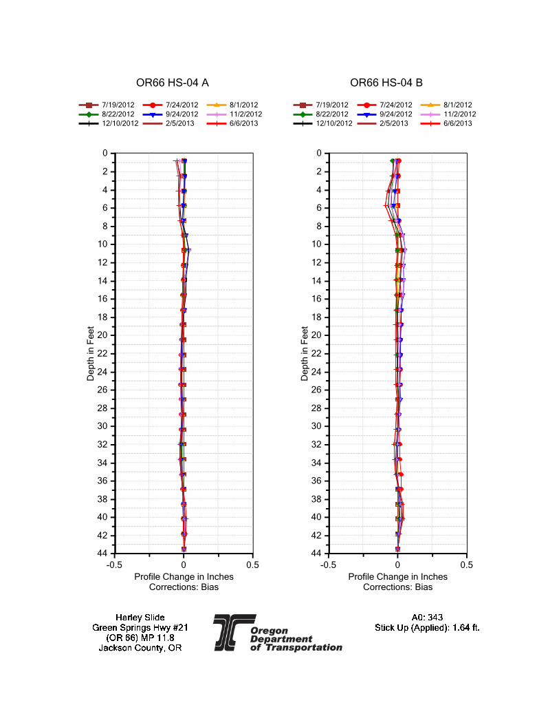
Slope Indicator, QC-Type 2.75 inch outside diameter, inclinometer casing was installed in each hole (HS-01, HS-02, HS-03 and HS-04) coupled with one Geokon VWT. The instrumentation was placed and back-filled with a cement-bentonite grout in accordance with OWRD regulations. Subsequent monitoring was performed with routine manual data collection methods by Region 3 Geology personnel. Data were collected and plotted with a graphical representation of the ground movement. Depth to the slide plane is reported in feet bgs on the drillhole logs in Appendix B with slide plane elevations included in Table 2. Graphical inclinometer data plots of cumulative and incremental displacements are shown in Appendix F. The inclinometer data shows deformation in drillholes HS-01, HS-02, and HS-03 and no displacement in HS-04. The slide plane in HS-01 is 18.8 feet bgs, in HS-02 is at 14.0 feet bgs, and in HS-03 is at 15.0 feet bgs (Appendix F). The cross-sections show the inferred limits of movement along this slide plane (Sheets GA01, GA02, GA03 and

Geology Report (Final) Highway 66 MP 11.8-12.0, Harley Slide June 16, 2017 Page 9 of 12
GA04 in Appendix A). The direction of movement in HS-01 is northwest with an azimuth of 309˚. The direction of movement in HS-02 is at an azimuth of 317˚. The direction of movement in HS-03 is similar to HS-01 with an azimuth of 301˚. The amount of displacement recorded in the inclinometers is greatest on the eastern portion of the slide (drillholes HS-01 and HS-02) with displacements along the basal plane ranging between 1.2 and 1.3 inches between July 19, 2012 and February 5, 2013. There was much less displacement recorded during the same timeframe on the western portion of the slide (drillhole HS-03) with a total of 0.3 inches of displacement. The inclinometer plots in Appendix F incorporate the stick-up for each inclinometer and also have a corrected A0 orientation in accordance with the resultant displacement direction. 3.0 DISCUSSION AND CONCLUSION The active landslide extends approximately 220 feet as measured along the highway stationing “M” Line between Sta. 19+70 and 21+90 with the headscarp extending into the northbound lane of OR 66 while extending between elevations 3,134 and 3,101 feet above MSL. The deepest portion of the active slide (Section C-C’ on Sheet GA04) extends through the current roadway asphalt and fills down to immediately above the basalt bedrock contact (Sheet GA04). The slide plane forms a concave shape, with the easterly portion (drillholes HS-01 and HS-02) of the slide dipping to northwest and the eastern portion (drillhole HS-03) dipping northerly. The concave shape of the basal plan is sub-parallel to the underlying bedrock units with basalt bedrock encountered in drillholes HS-01 and HS-02 and tuff overlying the basalt in drillholes HS-03 and HS-04 helps form the shape of the slide plane. The tuff unit likely terminates at or near where the drainage is located below the existing highway which is immediately west of drillholes HS-01 and HS-02. The active slide plane is currently located in subsurface materials with N Values ranging between eight and 10 blows-per-foot. In drillholes HS-01, HS-02 and HS-03, the slide plane does not penetrate into the bedrock units (tuff or basalt), but based on the slide morphology, it may penetrate into the first 0.5 feet of the decomposed tuff (Unit 4). Slide debris (Unit 3) was consistently found until encountering either basalt or tuff bedrock units. However, there are portions of the active slide where the failure is propagating up through the logged slide debris indicating the presence of older and deeper historic slide movements. The slide debris material (Unit 3) consists of decomposed colluvial material from the underlying tuff and basalt units. This slide debris is likely a combination of larger-scale slide activity in the topographic draw and former highway embankment-related slope movements. Based on the nature of this material, this unit likely contains cobble and boulder-sized debris even though these materials were not directly encountered in the drillholes. The recent surface mapping was tied-in with the slide plane displacements in the slope inclinometers for determining the active slide limits.

Geology Report (Final) Highway 66 MP 11.8-12.0, Harley Slide June 16, 2017 Page 10 of 12
The slide displacements are greatest near Section C-C’, where the highest concentration of pore pressures are located. The deepest portion of the failure is directly beneath the area where the surface drainage is located near Section C-C’. The combination of having the lowest bedrock depths with the highest pore pressures is believed to help the slide move the greatest in this area. The northernmost toe bulge of the mapped slide limits also is consistent with the displacement data recorded in the slope inclinometers in HS-01 and HS-02. As the pore pressures decrease both to the west and east of this drainage area, the historic slide debris gains additional shear strength causing the slide to propagate back to the surface. A review of the pore pressure data indicates that during periods of maximum pore pressure readings, much of the slide is at or near fully saturated conditions with artesian pore pressures measured in HS-03. Pore pressures were significantly lower in HS-04 but this is likely because of the VWT being installed well below the bedrock contact, indicating a separate aquifer condition in drillhole HS-04 when compared with the groundwater conditions recorded in drillholes HS-01, HS-02 and HS-03. 4.0 LIMITATIONS The recommendations presented in this report and its appendices are based on the data obtained from the subsurface explorations performed at the locations indicated in Sheets GA01, GA02, GA03 and GA04 in Appendix A. The subsurface explorations have provided detailed information at specific locations within the project area. However, variations in soil and rock conditions may exist between the test holes and groundwater levels may fluctuate periodically. The data shown in the exploration log of each test hole applies only to that particular test hole drilled on the dates indicated and is not intended to be conclusive as to the character of any material or conditions between or around the test holes (see Standard Specification 00120.25). Any interpretation or evaluation of this report by individuals outside of the Oregon Department of Transportation is done so at the sole risk of the individuals. The nature and extent of any variations in subsurface materials or conditions may not become evident until construction. If subsurface conditions different than those identified in the test holes are observed, or are encountered during construction, or appear to be present beneath, or beyond excavations the Geotechnical Engineer, or the Project Geologist should be advised at once so that they can observe and review these conditions and reconsider the design recommendations where necessary. It is recommended that construction operations relating to earthwork and foundations be observed by the Geotechnical Engineer or the Project Geologist to determine if the work is proceeding in accordance with the intent of the geotechnical recommendations and to allow for design changes as necessary.

Geology Report (Final) Highway 66 MP 11.8-12.0, Harley Slide June 16, 2017 Page 11 of 12
5.0 REFERENCES Oregon Department of Transportation, Highway Division, 1987, Soil and Rock Classification Manual. Peterson, Kulm, and Gray, 1986, Geologic Map of Ocean Floor off Oregon and the Adjacent Continental Margin, Oregon Department of Geology and Mineral Industries, GMS-42 Smith, R. L, and Roe, W. P., 2015, Oregon Department of Geology and Mineral Industries Oregon Geologic Data Compilation, Release No. 6 OGDC-6 (Statewide) Wiley, J. Thomas, McClaughry D. Jason, and D’Allura, A. Jad, 2011, Geologic Database and Generalized Geologic Map of Bear Creek Valley, Jackson County, Oregon, Oregon Department of Geology and Mineral Industries


APPENDIX A
Data Sheets GA01, GA02, GA03 and GA04


APPENDIX B
Drillhole Logs

0.0 - 10.5(Unit-1); SandyGRAVEL with tracesilt, GW; brown andgray, nonplastic, dryto damp, mediumdense to dense, fineto coarse-grainedsand, fine tocoarse-grainedangular gravel; (Fill)
10.5 - 19.8(Unit-3); CLAY withsome sand tracegravel, CH, black tobrown, highplasticity, moist,medium stiff to stiff;(Slide Debris)
X- 1 (0.0-2.5) Advance Auger
N- 1 (2.5-4.0) Sandy GRAVEL with trace silt, GW; brownand gray, nonplastic, damp, medium dense, fine tocoarse grained sand, angular, fine to coarse-grainedgravel, (Fill).
X- 2 (4.0-5.0) Advance Auger
N- 2 (5.0-6.5) Sandy GRAVEL, GW; gray, nonplastic,dry, medium dense, fine to coarse-grained sand, angular,fine to coarse-grained gravel, (Fill).
X- 3 (6.5-7.5) Advance Auger
N- 3 (7.5-9.0) Sandy GRAVEL, GW; gray, nonplastic,dry, dense, fine to coarse-grained sand, angular, fine tocoarse-grained gravel, (Fill).
X- 4 (9.0-10.0) Advance Auger
N- 4 (10.0-11.5) (10.0'-10.5') GRAVEL with some sand,GW; black, nonplastic, damp, very loose, (Fill),(10.5'-11.5') CLAY with some sand trace gravel, CH,black, high-plasticity, moist, medium stiff, (Slide Debris).
X- 5 (11.5-12.5) Advance Auger
N- 5 (12.5-14.0) CLAY with some sand trace gravel, CH,black, high-plasticity, moist, medium stiff, (Slide Debris).Lab No. 12-003793, gravel=11%, sand=19.9%,P200=69.1%, LL=68, PI=40.
U- 1 (14.0-16.0) CLAY with some sand trace gravel, CH,black, high-plasticity, moist, (Slide Debris).
N- 6 (16.0-17.5) (16.0'-17.0') CLAY with some sand tracegravel, CH; black, high-plasticity, moist, stiff, (SlideDebris).(17.0'-17.5') CLAY with some sand trace gravel, CH;brown, high-plasticity, damp, stiff, (Slide Debris).N- 7 (17.5-19.0) CLAY with some sand trace gravel, CH;brown, high-plasticity, damp, medium stiff, (Slide Debris).Lab No. 12-003794, gravel=6%, sand=28.9%,P200=65.1%, LL=92, PI=69.
"M" Sta. 21+08.3; -7.9feet left
Drilling method 4" IDHSA (0'-20')
Asphalt, sandand gravel layer at 10'
VWT set at 19', 32.1 C,8787.9, SN 1122987
X1
N1
X2
N2
X3
N3
X4
N4
X5
N5
U1
N6
N7
Slide plane 18.8'
6.72' initial and high
10.78' low
40
40
47
27
73
55
40
77
41
33
5-5-6
7-5-12
26-18-15
2-2-2
1-2-5
200-250-350-400
2-5-6
1-3-5
Slide plane 18.8'
7/26/12
11/17/12
July 11, 2012
Test Type
Hwy 66
CME 850
Start Date End Date
Purpose
County
Driller
July 11, 2012
DRILL LOGOREGON DEPARTMENT OF TRANSPORTATION
Project
Highway
Hole Location
Equipment
Project Geologist
Typical Drilling AbbreviationsRock Abbreviations
HS-01
PE001882
18906
3132.5 ft
Hole No.
E.A. No.
Key No.
Start Card No.
Bridge No.
Ground Elev.
Tube Height35.0 ft
62,082.58
Drilling RemarksLW - Lost WaterWR - Water ReturnWC - Water ColorDP - Down PressureDR - Drill RateDA - Drill Action
Recorder
Total Depth
45,981.33
Jason Garwood
Jackson
Landslide Investigation
Jason/HazTec
Kim Wyttenberg
OR 66 MP 11.8
2
ShapePl - PlanarC - CurvedU - UndulatingSt - SteppedIr - Irregular
DiscontinuityJ - JointF - FaultB - BeddingFo - FoliationS - Shear
Northing: Easting:
Page of1
Surface RoughnessP - PolishedSl - SlickensidedSm - SmoothR - RoughVR - Very Rough
Drilling MethodsWL - Wire LineHS - Hollow Stem AugerDF - Drill FluidSA - Solid AugerCA - Casing AdvancerHA - Hand Auger
"A" - Advancer"X" - Auger"C" - Core"N" - Standard Penetration Test"U" - Undisturbed Sample"D" - Oversize Split Spoon Sample
SOIL: Soil Name, USCS, Color, Plasticity,
Unit Description
Discontinuity Spacing, Joint Filling,Core Recovery, Formation Name.
Material Description
Moisture, Consistency/Relative Density,Texture, Cementation, Structure, Origin.
ROCK: Rock Name, Color, Weathering, Hardness,
Tes
t Typ
e, N
o.
Dep
th (
ft)
19
0
Soil
Dri
ving
Res
ista
nce
Bac
kfil
l/In
stru
men
tati
on
Gra
phic
Log
Per
cent
Nat
ural
Moi
stur
e
Per
cent
Rec
over
y
Wat
er L
evel
/D
ate
Dri
llin
gM
etho
ds, S
ize
and
Rem
arks
Rock
5
10
15
Dis
cont
inui
ty D
ata
Or
RQ
D%
OD
OT
DR
ILL
LOG
H
AR
LEY
SLI
DE
.GP
J O
DO
T_M
AN
.GD
T 4
/21/
17

19.8 - 35.0(Unit-7); BASALT,light gray, fresh, veryhard, wide jointed;(Roxy Formation)
X- 6 (19.0-19.9) Advance Auger
N- 8 (19.9-20.0) No RecoveryC- 1 (20.0-25.0) BASALT, light gray, fresh, very hard,wide jointed, CaCO3 in-fill vugs, (Roxy Formation).Lab No. 13-000284, (20.0'-20.7'), UCS=19,506.2 psi.
C- 2 (25.0-30.0) BASALT, light gray, fresh, very hard,wide jointed, CaCO3 vugs, (Roxy Formation).Lab No. 13-000285, (26.6'-27.2'),UCS=22,335.9 psi.
C- 3 (30.0-35.0) BASALT, light gray, fresh, very hard,wide jointed, CaCO3 vugs, (Roxy Formation).
(35.0-35.0) Bottom of hole at 35.0 feet bgs.
Bedrock contact 19.8'
Drilling method changedto HQ3-WL, (20'-35')
Installed QC type 2.75"inclinometer tube to 35'Cement Bentonite Grout(35'-0')
Bottom of hole 35'
X6
N8C1
C2
C3
092
100
100
50/0R5
RQD = 92
R5RQD = 100
R5RQD = 100
Project Name OR 66 MP 11.8 Hole No. HS-01 Page of2 2
SOIL: Soil Name, USCS, Color, Plasticity,
Unit Description
Discontinuity Spacing, Joint Filling,Core Recovery, Formation Name.
Material Description
Moisture, Consistency/Relative Density,Texture, Cementation, Structure, Origin.
ROCK: Rock Name, Color, Weathering, Hardness,T
est T
ype,
No.
Dep
th (
ft)
48
19
Soil
Dri
ving
Res
ista
nce
Bac
kfil
l/In
stru
men
tati
on
Gra
phic
Log
Per
cent
Nat
ural
Moi
stur
e
Per
cent
Rec
over
y
Wat
er L
evel
/D
ate
Dri
llin
gM
etho
ds, S
ize
and
Rem
arks
Rock
20
25
30
35
40
45
Dis
cont
inui
ty D
ata
Or
RQ
D%
OD
OT
DR
ILL
LOG
H
AR
LEY
SLI
DE
.GP
J O
DO
T_M
AN
.GD
T 4
/21/
17

0.0 - 15.6(Unit-3); Sandy CLAYwith trace to somegravel, CH; darkbrown to brown,high-plasticity, dampto moist, medium stiffto stiff, fine tocoarse-grained sand;(Slide Debris)
15.6 - 21.0(Unit-5); Clayey SANDwith some gravel, SCto SAND with someclay and gravel,SP-SC , brown todark brown, low tomedium-plasticity,moist to wet, denseto very dense, fine tocoarse-grained sand,
X- 1 (0.0-2.5) Advance Auger
N- 1 (2.5-4.0) Sandy CLAY with some gravel, CH; darkbrown to brown, high-plasticity, moist, medium stiff, (SlideDebris).Lab No. 12-003795, gravel=19%, sand=34.5%,P200=46.5%, LL=61, PI=40.X- 2 (4.0-5.0) Advance Auger
N- 2 (5.0-6.5) Sandy CLAY with trace gravel, CH; brown,high-plasticity, moist, stiff, fine to coarse-grained sand,(Slide Debris).
X- 3 (6.5-7.5) Advance Auger
N- 3 (7.5-9.0) Sandy CLAY with trace gravel, CH; brown,high-plasticity, moist, stiff, fine to coarse-grained sand,(Slide Debris).Lab No. 12-003796, gravel=8%, sand=33.7%,P200=58.3%, LL=58, PI=39.X- 4 (9.0-10.0) Advance Auger
N- 4 (10.0-11.5) Sandy CLAY with trace gravel, CH;brown, high-plasticity, moist, stiff, fine to coarse-grainedsand, (Slide Debris).
X- 5 (11.5-12.5) Advance Auger
N- 5 (12.5-14.0) Sandy CLAY with trace gravel, CH;brown, high-plasticity, moist, stiff, fine to coarse-grainedsand, (Slide Debris).Lab No. 12-003797, gravel=10%, sand=31.7%,P200=58.3%, LL=74, PI=52.X- 6 (14.0-15.0) Advance Auger
N- 6 (15.0-16.5) (15.0'-15.5') Sandy CLAY with tracegravel, CH; brown, high-plasticity, moist, stiff, fine tocoarse-grained sand, (Slide Debris).Lab No. 12-003798, gravel=10%, sand=21.8%,P200=68.2%, LL=82, PI=57.(15.5'-16.5') Clayey SAND with some gravel, SC; brown,medium-plasticity, moist, dense, fine to coarse-grainedsand, Decomposed Basalt, (Roxy Formation).X- 7 (16.5-17.5) Advance AugerN- 7 (17.5-19.0) Clayey SAND with some gravel, SC;brown, medium-plasticity, moist, dense, fine tocoarse-grained sand, Decomposed Basalt, (RoxyFormation).Lab No. 12-003801, gravel=18%, sand=45.4%,P200=36.6%, LL=37, PI=19.
"M" Sta. 21+56.8; -62.2feet left
Drilling method 4" IDHSA (0'-20')
Bedrock contact 15.6'
VWT set at 19', 34.4 C,8870.1, SN 1122993
X1
N1
X2
N2
X3
N3
X4
N4
X5
N5
X6
N6
X7
N7
X8
Slide Plane at 14'
1.02' highest reading
Initial reading
18.50' lowest reading
53
53
67
77
90
80
53
24
30
30
33
15
3-3-4
2-2-5
2-4-6
2-4-5
2-5-6
2-9-12
8-7-34
Slide Plane at 14'
1/30/13
7/26/12
10/9/12
July 12, 2012
Test Type
Hwy 66
CME 850
Start Date End Date
Purpose
County
Driller
July 12, 2012
DRILL LOGOREGON DEPARTMENT OF TRANSPORTATION
Project
Highway
Hole Location
Equipment
Project Geologist
Typical Drilling AbbreviationsRock Abbreviations
HS-02
PE001882
18906
3106.9 ft
Hole No.
E.A. No.
Key No.
Start Card No.
Bridge No.
Ground Elev.
Tube Height41.0 ft
62,134.34
Drilling RemarksLW - Lost WaterWR - Water ReturnWC - Water ColorDP - Down PressureDR - Drill RateDA - Drill Action
Recorder
Total Depth
45,938.30
Jason Garwood
Jackson
Landslide Investigation
Jason/HazTec
Kim Wyttenberg
OR 66 MP 11.8
2
ShapePl - PlanarC - CurvedU - UndulatingSt - SteppedIr - Irregular
DiscontinuityJ - JointF - FaultB - BeddingFo - FoliationS - Shear
Northing: Easting:
Page of1
Surface RoughnessP - PolishedSl - SlickensidedSm - SmoothR - RoughVR - Very Rough
Drilling MethodsWL - Wire LineHS - Hollow Stem AugerDF - Drill FluidSA - Solid AugerCA - Casing AdvancerHA - Hand Auger
"A" - Advancer"X" - Auger"C" - Core"N" - Standard Penetration Test"U" - Undisturbed Sample"D" - Oversize Split Spoon Sample
SOIL: Soil Name, USCS, Color, Plasticity,
Unit Description
Discontinuity Spacing, Joint Filling,Core Recovery, Formation Name.
Material Description
Moisture, Consistency/Relative Density,Texture, Cementation, Structure, Origin.
ROCK: Rock Name, Color, Weathering, Hardness,
Tes
t Typ
e, N
o.
Dep
th (
ft)
20
0
Soil
Dri
ving
Res
ista
nce
Bac
kfil
l/In
stru
men
tati
on
Gra
phic
Log
Per
cent
Nat
ural
Moi
stur
e
Per
cent
Rec
over
y
Wat
er L
evel
/D
ate
Dri
llin
gM
etho
ds, S
ize
and
Rem
arks
Rock
5
10
15
Dis
cont
inui
ty D
ata
Or
RQ
D%
OD
OT
DR
ILL
LOG
H
AR
LEY
SLI
DE
.GP
J O
DO
T_M
AN
.GD
T 4
/21/
17

Decomposed Basalt;(Roxy Formation)
21.0 - 31.5(Unit-6); BASALT,orange-brown togray, moderatelyweathered, very softto very hard, veryclose to closejointing; (RoxyFormation)
31.5 - 41.0(Unit-7); BASALT,gray, fresh, very hard,wide jointed; (RoxyFormation)
X- 8 (19.0-20.0) Advance AugerN- 8 (20.0-20.5) SAND with some clay and gravel, SC;dark brown, low plasticity, wet, very dense, medium tocoarse-grained sand, Decomposed Basalt, (RoxyFormation).C- 1 (20.5-21.0) No Recovery - Decomposed Basalt,(Roxy Formation).C- 2 (21.0-26.0) BASALT, orange-brown to gray,moderately weathered, soft, very close jointed, (RoxyFormation).
C- 3 (26.0-31.0) BASALT, orange-brown to gray,moderately weathered, soft to very hard, very closejointed, (Roxy Formation).Lab No. 13-000286, (26.0'-26.5') BASALT, gray, fresh,very hard, close jointed, UCS=22,832 psi.
C- 4 (31.0-36.0) BASALT, orange-brown, moderatelyweathered, soft, (31.5'-36.0') BASALT, gray, fresh, veryhard, wide jointed, (Roxy Formation).Lab No. 13-000287, UCS=24,783 psi.
C- 5 (36.0-41.0) BASALT, gray, fresh, very hard, widejointed, (Roxy Formation).
(41.0-41.0) Bottom of hole at 41.0 feet bgs.
wet spoon
Drilling method changedto HQ3-WL, (20'-41')
Installed QC type 2.75"inclinometer tube to 41'Cement Bentonite Grout(41'-0')
Bottom of hole at 41'
N8
C1
C2
C3
C4
C5
90
0
92
68
82
100
50/6"
R0RQD = 0
R2RQD = 0
R2RQD = 9
R5RQD = 100
R5RQD = 100
Project Name OR 66 MP 11.8 Hole No. HS-02 Page of2 2
SOIL: Soil Name, USCS, Color, Plasticity,
Unit Description
Discontinuity Spacing, Joint Filling,Core Recovery, Formation Name.
Material Description
Moisture, Consistency/Relative Density,Texture, Cementation, Structure, Origin.
ROCK: Rock Name, Color, Weathering, Hardness,T
est T
ype,
No.
Dep
th (
ft)
50
20
Soil
Dri
ving
Res
ista
nce
Bac
kfil
l/In
stru
men
tati
on
Gra
phic
Log
Per
cent
Nat
ural
Moi
stur
e
Per
cent
Rec
over
y
Wat
er L
evel
/D
ate
Dri
llin
gM
etho
ds, S
ize
and
Rem
arks
Rock
25
30
35
40
45
Dis
cont
inui
ty D
ata
Or
RQ
D%
OD
OT
DR
ILL
LOG
H
AR
LEY
SLI
DE
.GP
J O
DO
T_M
AN
.GD
T 4
/21/
17

0.0 - 3.0(Unit-2); CLAY withtrace sand, CH;brown to black,high-plasticity, moist,soft; (Drill Road Fill)3.0 - 17.1(Unit-3); CLAY withtrace to some sand,CH, dark gray, black,gray-brown andorange-brownhigh-plasticity, moistto wet, soft to stiff,fine to coarse-grainedsand; (Slide Debris)
17.1 - 29.0(Unit-4); CLAY withtrace sand, CH;orange-brown togray-brown, highplasticity, moist, verystiff, DecomposedTuff; (RoxyFormation)
X- 1 (0.0-2.5) Advance Auger
N- 1 (2.5-4.0) CLAY with trace sand, CH; brown to black,high-plasticity, moist, soft, (Drill Road Fill).
X- 2 (4.0-5.0) Advance Auger
N- 2 (5.0-6.5) CLAY with some sand, CH; dark gray toblack, high-plasticity, wet, soft, fine to coarse-grainedsand, (Slide Debris).Lab No. 12-003799, gravel=1%, sand=15.3%,P200=83.7%, LL=96, PI=70.X- 3 (6.5-7.5) Advance AugerN- 3 (7.5-9.0) CLAY with trace sand, CH; dark gray togray-brown, high-plasticity, moist, medium stiff, (SlideDebris).
X- 4 (9.0-10.0) Advance Auger
N- 4 (10.0-11.5) CLAY with trace sand, CH; gray-brown,high-plasticity, moist, medium stiff, (Slide Debris).Lab No. 12-003800, gravel=1%, sand=14.8%,P200=84.2%, LL=101, PI=76.X- 5 (11.5-12.5) Advance Auger
N- 5 (12.5-14.0) CLAY with some sand, CH; gray-brown,high-plasticity, moist, stiff, fine to coarse-grained sand,(Slide Debris).Lab No. 12-003802, gravel=4%, sand=15.6%,P200=80.4%, LL=76, PI=50.X- 6 (14.0-15.0) Advance AugerN- 6 (15.0-16.5) CLAY, CH; orange-brown,high-plasticity, moist, stiff, Decomposed Tuff, (SlideDebris).(15.0'-15.5') Lab No. 12-003803, gravel=0%, sand=4.5%,P200=95.5%, LL=126, PI=99.(15.5'-16.5') Lab No. 12-003804, gravel=0%,sand=10.5%,P200=89.5%, LL=94, PI=66.X- 7 (16.5-17.5) Advance AugerN- 7 (17.5-19.0) CLAY with trace sand, CH;orange-brown, high-plasticity, moist, very stiff,Decomposed Tuff, (Roxy Formation).Lab No. 12-003809, gravel=1%, sand=6.4%,P200=92.6%, LL=99, PI=70.X- 8 (19.0-20.0) Advance AugerN- 8 (20.0-21.5) CLAY with trace sand, CH;orange-brown, high-plasticity, moist, very stiff,Decomposed Tuff, (Roxy Formation).Lab No. 12-003805, gravel=0%, sand=10.6%,P200=89.4%, LL=71, PI=45.X- 9 (21.5-22.5) Advance AugerN- 9 (22.5-24.0) CLAY with trace sand, CH;orange-brown to gray-brown, high-plasticity, moist, verystiff Decomposed Tuff, (Roxy Formation).Lab No. 12-003806, gravel=0%, sand=12.6%,
"M" Sta. 20+31.3; -80.2feet left
Drilling method 4" IDHSA (0'-35')wet spoon
Bedrock contact 17.1'
VWT set at 19', 22.0 C,9026.4, SN 1122984
GW pressured- artesianconditions
X1
N1
X2
N2
X3
N3
X4
N4
X5
N5
X6
N6
X7
N7
X8
N8
X9
N9
X10
Slide Plane 15'
0.0' artesian
1.3' initial
8.95' Low
20
73
100
100
87
60
87
73
80
52
44
40
42
45
36
32
Push-1-2
1-2-2
1-2-4
2-3-4
2-5-6
2-4-6
2-8-11
1-5-13
5-7-12
Slide Plane 15'
5/1/13
7/27/12
9/20/13
July 13, 2012
Test Type
Hwy 66
CME 850
Start Date End Date
Purpose
County
Driller
July 13, 2012
DRILL LOGOREGON DEPARTMENT OF TRANSPORTATION
Project
Highway
Hole Location
Equipment
Project Geologist
Typical Drilling AbbreviationsRock Abbreviations
HS-03
PE001882
18906
3112.5 ft
Hole No.
E.A. No.
Key No.
Start Card No.
Bridge No.
Ground Elev.
Tube Height51.0 ft
62,083.26
Drilling RemarksLW - Lost WaterWR - Water ReturnWC - Water ColorDP - Down PressureDR - Drill RateDA - Drill Action
Recorder
Total Depth
45,895.53
Jason Garwood
Jackson
Landslide Investigation
Jason/HazTec
Kim Wyttenberg
OR 66 MP 11.8
2
ShapePl - PlanarC - CurvedU - UndulatingSt - SteppedIr - Irregular
DiscontinuityJ - JointF - FaultB - BeddingFo - FoliationS - Shear
Northing: Easting:
Page of1
Surface RoughnessP - PolishedSl - SlickensidedSm - SmoothR - RoughVR - Very Rough
Drilling MethodsWL - Wire LineHS - Hollow Stem AugerDF - Drill FluidSA - Solid AugerCA - Casing AdvancerHA - Hand Auger
"A" - Advancer"X" - Auger"C" - Core"N" - Standard Penetration Test"U" - Undisturbed Sample"D" - Oversize Split Spoon Sample
SOIL: Soil Name, USCS, Color, Plasticity,
Unit Description
Discontinuity Spacing, Joint Filling,Core Recovery, Formation Name.
Material Description
Moisture, Consistency/Relative Density,Texture, Cementation, Structure, Origin.
ROCK: Rock Name, Color, Weathering, Hardness,
Tes
t Typ
e, N
o.
Dep
th (
ft)
25
0
Soil
Dri
ving
Res
ista
nce
Bac
kfil
l/In
stru
men
tati
on
Gra
phic
Log
Per
cent
Nat
ural
Moi
stur
e
Per
cent
Rec
over
y
Wat
er L
evel
/D
ate
Dri
llin
gM
etho
ds, S
ize
and
Rem
arks
Rock
5
10
15
20
Dis
cont
inui
ty D
ata
Or
RQ
D%
OD
OT
DR
ILL
LOG
H
AR
LEY
SLI
DE
.GP
J O
DO
T_M
AN
.GD
T 4
/21/
17

29.0 - 35.1(Unit-5); ClayeySAND, SC to SANDwith some silt,SP-SM;orange-brown, grayto red-brown,nonplastic tolow-plasticity, moistto wet, very dense,Decomposed Basalt;(Roxy Formation)35.1 - 51.0(Unit-7); BASALT,gray, fresh, hard tovery hard, close towide jointed; (RoxyFormation)
P200=87.4%, LL=70, PI=45.X- 10 (24.0-25.0) Advance AugerN- 10 (25.0-26.5) CLAY with trace sand, CH;orange-brown to gray-brown, high-plasticity, moist, verystiff, Decomposed Tuff, (Roxy Formation).X- 11 (26.5-27.5) Advance AugerN- 11 (27.5-29.0) CLAY with trace sand, CH;orange-brown to gray-brown, high-plasticity, moist, verystiff, Decomposed Tuff, (Roxy Formation).Lab No. 12-003810, gravel=0%, sand=7.7%,P200=92.3%, LL=68, PI=42.X- 12 (29.0-30.0) Advance AugerN- 12 (30.0-31.5) Clayey SAND, SC; orange-brown,low-plasticity, moist, very dense, Decomposed Basalt,(Roxy Formation).
X- 13 (31.5-32.5) Advance Auger
N- 13 (32.5-32.9) SAND with some silt, SP-SM;orange-brown, nonplastic, wet, very dense, DecomposedBasalt, (Roxy Formation).X- 14 (32.9-35.0) Advance Auger
N- 14 (35.0-35.2) SAND with trace silt, SP, gray tored-brown, nonplastic, moist, very dense, DecomposedBasalt, (Roxy Formation).C- 1 (35.2-36.0) BASALT, gray, fresh, hard, close jointed,(Roxy Formation).Lab No. 13-000288 (35.1'-35.6') UCS=9,370.8 psi.C- 2 (36.0-41.0) BASALT, gray, fresh, hard, wide jointed,(Roxy Formation).
C- 3 (41.0-46.0) BASALT, gray, fresh, very hard, widejointed, (Roxy Formation).Lab No. 13-000289, (44.0'-44.6'), UCS=21,399.1 psi.
C- 4 (46.0-51.0) BASALT, gray, fresh, very hard, widejointed, (Roxy Formation).
(51.0-51.0) Bottom of hole at 51.0 feet bgs.
wet spoon
Drilling method changedto HQ3-WL, (35'-51')
Installed QC type 2.75"inclinometer tube to 51'Cement Bentonite Grout(51'-0')
Bottom of hole 51'
N10
X11
N11
X12
N12
X13
N13X14
N14C1C2
C3
C4
93
73
100
25
10010096
100
100
28
6-8-12
11-13-14
14-28-36
50/5"
50/2"R4
RQD = 100R4
RQD = 96
R5RQD = 100
R5RQD = 100
Project Name OR 66 MP 11.8 Hole No. HS-03 Page of2 2
SOIL: Soil Name, USCS, Color, Plasticity,
Unit Description
Discontinuity Spacing, Joint Filling,Core Recovery, Formation Name.
Material Description
Moisture, Consistency/Relative Density,Texture, Cementation, Structure, Origin.
ROCK: Rock Name, Color, Weathering, Hardness,T
est T
ype,
No.
Dep
th (
ft)
63
25
Soil
Dri
ving
Res
ista
nce
Bac
kfil
l/In
stru
men
tati
on
Gra
phic
Log
Per
cent
Nat
ural
Moi
stur
e
Per
cent
Rec
over
y
Wat
er L
evel
/D
ate
Dri
llin
gM
etho
ds, S
ize
and
Rem
arks
Rock
30
35
40
45
50
55
60
Dis
cont
inui
ty D
ata
Or
RQ
D%
OD
OT
DR
ILL
LOG
H
AR
LEY
SLI
DE
.GP
J O
DO
T_M
AN
.GD
T 4
/21/
17

0.0 - 7.0(Unit-1); Clayey SANDwith some gravel, SC,CLAY with tracesand, CH; dark grayto dark brown,medium tohigh-plasticity, dry tomoist, medium denseto medium stiff, fineto coarse-grainedsand, fine tocoarse-grainedangular gravel; (Fill)
7.0 - 29.0(Unit-4); CLAY withtrace to some sand,CH, Sandy CLAY, CHto Clayey SAND withsome gravel, SC;orange-brown, brown,light brown,gray-brown,red-brown and white,high plasticity, dampto moist, very stiff tohard and mediumdense, fine tocoarse-grained sand,fine-grained, angulargravel, DecomposedTuff; (RoxyFormation)
X- 1 (0.0-2.5) Advance Auger
N- 1 (2.5-4.0) Clayey SAND with some gravel, SC; darkgray, medium-plasticity, dry, medium dense, fine tocoarse-grained sand, fine to coarse-grained angulargravel, (Fill).
X- 2 (4.0-5.0) Advance Auger
N- 2 (5.0-6.5) CLAY with trace sand, CH; dark gray todark brown, high-plasticity, moist, medium stiff, (Fill).Lab No. 12-003807, gravel=0%, sand=5.8%,P200=94.2%, LL=119, PI=86.
X- 3 (6.5-7.5) Advance Auger
N- 3 (7.5-9.0) CLAY with some sand, CH; orange-brownto brown, high-plasticity, moist, very stiff, fine tocoarse-grained sand, Decomposed Tuff, (RoxyFormation).Lab No. 12-003308, gravel=1%, sand=24.7%,P200=74.3%, LL=66, PI=45.X- 4 (9.0-10.0) Advance Auger
N- 4 (10.0-11.5) No Recovery.
X- 5 (11.5-12.5) Advance Auger
N- 5 (12.5-14.0) Sandy CLAY, CH; gray-brown,high-plasticity, moist, very stiff, fine to coarse-grainedsand, Decomposed Tuff, (Roxy Formation).
X- 6 (14.0-15.0) Advance Auger
N- 6 (15.0-16.5) CLAY with trace sand, CH;orange-brown to light brown, high-plasticity, moist, verystiff, Decomposed Lapilli Tuff, (Roxy Formation).Lab No. 12-003811, gravel=0%, sand=9%,P200=91%, LL=81, PI=57.X- 7 (16.5-17.5) Advance Auger
N- 7 (17.5-19.0) CLAY with trace sand, CH; light brownto red-brown, high-plasticity, damp, very stiff,Decomposed Tuff, (Roxy Formation).Lab No. 12-003812, gravel=0%, sand=8.3%,P200=91.7%, LL=88, PI=66.X- 8 (19.0-20.0) Advance Auger
"M" Sta. 19+61.3; -8.4feet left
Drilling method 4" IDHSA (0'-30')
X1
N1
X2
N2
X3
N3
X4
N4
X5
N5
X6
N6
X7
N7
X8
30
34
43
0
27
93
100
37
28
35
26
9-6-6
3-3-5
6-8-11
3-6-6
7-7-8
3-6-10
4-9-12
July 10, 2012
Test Type
Hwy 66
CME 850
Start Date End Date
Purpose
County
Driller
July 10, 2012
DRILL LOGOREGON DEPARTMENT OF TRANSPORTATION
Project
Highway
Hole Location
Equipment
Project Geologist
Typical Drilling AbbreviationsRock Abbreviations
HS-04
PE001882
18906
3141.5 ft
Hole No.
E.A. No.
Key No.
Start Card No.
Bridge No.
Ground Elev.
Tube Height45.0 ft
62,002.14
Drilling RemarksLW - Lost WaterWR - Water ReturnWC - Water ColorDP - Down PressureDR - Drill RateDA - Drill Action
Recorder
Total Depth
45,877.70
Jason Garwood
Jackson
Landslide Investigation
Jason/HazTec
Kim Wyttenberg
OR 66 MP 11.8
2
ShapePl - PlanarC - CurvedU - UndulatingSt - SteppedIr - Irregular
DiscontinuityJ - JointF - FaultB - BeddingFo - FoliationS - Shear
Northing: Easting:
Page of1
Surface RoughnessP - PolishedSl - SlickensidedSm - SmoothR - RoughVR - Very Rough
Drilling MethodsWL - Wire LineHS - Hollow Stem AugerDF - Drill FluidSA - Solid AugerCA - Casing AdvancerHA - Hand Auger
"A" - Advancer"X" - Auger"C" - Core"N" - Standard Penetration Test"U" - Undisturbed Sample"D" - Oversize Split Spoon Sample
SOIL: Soil Name, USCS, Color, Plasticity,
Unit Description
Discontinuity Spacing, Joint Filling,Core Recovery, Formation Name.
Material Description
Moisture, Consistency/Relative Density,Texture, Cementation, Structure, Origin.
ROCK: Rock Name, Color, Weathering, Hardness,
Tes
t Typ
e, N
o.
Dep
th (
ft)
20
0
Soil
Dri
ving
Res
ista
nce
Bac
kfil
l/In
stru
men
tati
on
Gra
phic
Log
Per
cent
Nat
ural
Moi
stur
e
Per
cent
Rec
over
y
Wat
er L
evel
/D
ate
Dri
llin
gM
etho
ds, S
ize
and
Rem
arks
Rock
5
10
15
Dis
cont
inui
ty D
ata
Or
RQ
D%
OD
OT
DR
ILL
LOG
H
AR
LEY
SLI
DE
.GP
J O
DO
T_M
AN
.GD
T 4
/21/
17

29.0 - 30.5(Unit-5); Clayey SANDwith some gravel, SC;light brown,medium-plasticity,damp, very dense,fine to coarse-grainedsand, fine tocoarse-grainedangular gravel,Decomposed Basalt;(Roxy Formation)30.5 - 36.5(Unit-6); BASALT,orange-brown to lightgray, moderatelyweathered, soft, veryclose jointed; (RoxyFormation)36.5 - 45.0(Unit-7); BASALT,light gray, fresh,hard, close tomoderately closejointed; (RoxyFormation)
N- 8 (20.0-21.5) Sandy CLAY, CH; orange-brown, lightbrown to white, high-plasticity, damp, very stiff, fine tocoarse-grained sand, Decomposed Tuff, (RoxyFormation).Lab No. 12-003813, gravel=1%, sand=43.8%,P200=55.2%, LL=77, PI=56.X- 9 (21.5-22.5) Advance Auger
N- 9 (22.5-24.0) CLAY with some sand, CH;orange-brown to light brown, high-plasticity, damp, hard,fine to coarse-grained sand, Decomposed Tuff, (RoxyFormation).Lab No. 12-003814, gravel=0%, sand=14.3%,P200=85.7%, LL=75, PI=51.X- 10 (24.0-25.0) Advance Auger
N- 10 (25.0-26.5) Clayey SAND with some gravel, SC;orange-brown to red-brown, high-plasticity, damp,medium dense, fine to coarse-grained sand, fine-grainedangular gravel, Decomposed Tuff, (Roxy Formation).Lab No. 12-003815, gravel=21%, sand=46.6%,P200=32.4%, LL=49, PI=28.X- 11 (26.5-27.5) Advance Auger
N- 11 (27.5-29.0) Clayey SAND with some gravel, SC;orange-brown to light brown, high-plasticity, moist,medium dense, fine to coarse-grained sand, angularfine-grained gravel, Decomposed Tuff, (Roxy Formation).Lab No. 12-003816, gravel=20%, sand=47.9%,P200=32.1%, LL=51, PI=31.X- 12 (29.0-30.0) Advance Auger
N- 12 (30.0-30.5) Clayey SAND with some gravel, SC;light brown, medium-plasticity, damp, very dense, fine tocoarse-grained sand, fine to coarse-grained angulargravel, Decomposed Basalt, (Roxy Formation).C- 1 (30.5-33.0) BASALT, orange-brown to light gray,moderately weathered, soft, very close jointed, (RoxyFormation).
C- 2 (33.0-35.5) BASALT, orange-brown to light gray,moderately weathered, soft, very close jointed, (RoxyFormation).
C- 3 (35.5-39.5) (35.5'-36.5') BASALT, orange-brown tolight gray, moderately weathered, soft, very close jointed,(Roxy Formation).(36.5'-39.5') BASALT, light gray, fresh, soft, close jointed,(Roxy Formation).
C- 4 (39.5-40.5) BASALT, light gray, fresh, hard, closejointed, (Roxy Formation).
C- 5 (40.5-45.0) BASALT, light gray, fresh, hard, close tomoderately close jointed, (Roxy Formation).Lab No. 13-000290, (40.5'-41.1') UCS=9,913.3 psi.
(45.0-45.0) Bottom of hole at 45.0 feet bgs.
wet spoon 26'
Drilling method changedto HQ3-WL, (30'-45')
VWT set at 37', 29.4 C,8879.8, SN 1122989
Installed QC type 2.75"inclinometer tube to 45'Cement Bentonite Grout(45'-0')
Bottom of hole 45'
N8
X9
N9
X10
N10
X11
N11
X12
N12
C1
C2
C3
C4
C5
Basaltbedrockcontact 29'
High 26.05
Initial
Low 36.44
100
100
73
73
100
72
76
88
100
89
25
28
14
18
5-10-14
8-15-20
7-8-21
8-13-15
50/6"
R2RQD = 0
R2RQD = 0
R2RQD = 0
R4RQD = 90
R4RQD = 89
Basaltbedrockcontact 29'
5/18/13
7/26/12
10/22/12
Project Name OR 66 MP 11.8 Hole No. HS-04 Page of2 2
SOIL: Soil Name, USCS, Color, Plasticity,
Unit Description
Discontinuity Spacing, Joint Filling,Core Recovery, Formation Name.
Material Description
Moisture, Consistency/Relative Density,Texture, Cementation, Structure, Origin.
ROCK: Rock Name, Color, Weathering, Hardness,T
est T
ype,
No.
Dep
th (
ft)
50
20
Soil
Dri
ving
Res
ista
nce
Bac
kfil
l/In
stru
men
tati
on
Gra
phic
Log
Per
cent
Nat
ural
Moi
stur
e
Per
cent
Rec
over
y
Wat
er L
evel
/D
ate
Dri
llin
gM
etho
ds, S
ize
and
Rem
arks
Rock
25
30
35
40
45
Dis
cont
inui
ty D
ata
Or
RQ
D%
OD
OT
DR
ILL
LOG
H
AR
LEY
SLI
DE
.GP
J O
DO
T_M
AN
.GD
T 4
/21/
17

APPENDIX C
Core Photographs

Oregon Department of Transportation April 2017
CORE PHOTOGRAPHS
OR 66 Harley Slide
Jackson County, Oregon
Drillhole HS-01
Boxes 1 and 2 of 2

Oregon Department of Transportation April 2017
CORE PHOTOGRAPHS
OR 66 Harley Slide
Jackson County, Oregon
Drillhole HS-02
Boxes 1 and 2 of 2

Oregon Department of Transportation April 2017
CORE PHOTOGRAPHS
OR 66 Harley Slide
Jackson County, Oregon
Drillhole HS-03
Boxes 1 and 2 of 2

Oregon Department of Transportation April 2017
CORE PHOTOGRAPHS
OR 66 Harley Slide
Jackson County, Oregon
Drillhole HS-04
Boxes 1 and 2 of 2

APPENDIX D
Laboratory Testing Data

LABORATORY TEST RESULTSLocation Index Testing
Boring, Test Pit, or Hand Auger Soil/Rock Classification Natural Atterburg Limits P - 200 Unit Wt. Max. Compressive Resistivity pHHole # Sample # Depth (ft) Description Unit USCS Moisture LL (%) PI (%) (%) γw(lb/ft3) Strength (psi) Ω-cm
HS-04 N2 5.00 fat CLAY Unit 1 CH 36.9 119 86 94.2HS-01 N5 12.50 sandy fat CLAY Unit 3 CH 41.3 68 40 69.1HS-01 N7 17.50 sandy fat CLAY Unit 3 CH 33.2 92 69 65.1HS-02 N1 2.50 clayey SAND with gravel Unit 3 CH 24.3 61 40 46.5HS-02 N3 7.50 sandy fat CLAY Unit 3 CH 29.6 58 39 58.3HS-02 N5 12.50 sandy fat CLAY Unit 3 CH 29.6 74 52 58.3HS-02 N6 15.00 sandy fat CLAY Unit 3 CH 33.3 82 57 68.2HS-03 N2 5.00 fat CLAY with sand Unit 3 CH 51.6 96 70 83.7HS-03 N4 10.00 fat CLAY with sand Unit 3 CH 43.6 101 76 84.2HS-03 N5 12.50 fat CLAY with sand Unit 3 CH 40.2 76 50 80.4HS-03 N6A 15.00 fat CLAY Unit 3 CH 42.2 126 99 95.5HS-03 N6B 15.50 fat CLAY Unit 3 CH 43.3 94 66 89.5HS-03 N7 17.50 fat CLAY Unit 4 CH 44.6 99 70 92.6HS-03 N8 20.00 fat CLAY Unit 4 CH 36.1 71 45 89.4HS-03 N9 22.50 fat CLAY Unit 4 CH 32.0 70 45 87.4HS-03 N11 27.50 fat CLAY Unit 4 CH 27.8 68 42 92.3HS-04 N3 7.50 fat CLAY with sand Unit 4 CH 27.8 66 45 74.3HS-04 N6 15.00 fat CLAY Unit 4 CH 35.3 81 57 91.0HS-04 N7 17.50 fat CLAY Unit 4 CH 25.8 88 66 91.7HS-04 N8 20.00 sandy fat CLAY Unit 4 CH 24.6 77 56 55.2HS-04 N9 22.50 fat CLAY Unit 4 CH 28.1 75 51 85.7HS-04 N10 25.00 clayey SAND with gravel Unit 4 SC 14.3 49 28 32.4HS-04 N11 27.50 clayey SAND with gravel Unit 4 SC 18.2 51 31 32.1HS-02 N7 17.50 clayey SAND with gravel Unit 5 SC 15.1 37 19 36.6
HS-01 C2 26.60 Basalt Unit 6 0.7 153.7 22,335.9HS-02 C3 26.00 Basalt Unit 6 1.1 160.6 22,831.7HS-01 C1 20.00 Basalt Unit 7 0.8 158.3 19,506.2HS-02 C4 33.50 Basalt Unit 7 1.0 158.0 24,783.0HS-03 C1 35.10 Basalt Unit 7 1.5 151.2 9,370.8HS-03 C3 44.00 Basalt Unit 7 0.8 158.1 21,399.1HS-04 C5 40.50 Basalt Unit 7 0.6 149.9 9,913.3
Laboratory Test Results Hwy: Green Springs Hwy 66 M.P. 11.8 E.A. #: PE002600 000 Date: April 2017
Harley Slide MP 11.8Oregon Department of Transportation
Table # 3
0102030405060708090
100110120130
0 10 20 30 40 50 60 70 80 90 100 110 120 130
Pla
stic
ity In
dex
(%)
Liquid Limit (%)
Unit 1 (Fill)
Unit 3 (Qls)
Unit 4 (Tuff-w)
Unit 5 (Bs-w)CL or OL
MH or OH
ML or OL
CH or OH CL or ML


APPENDIX E
Groundwater Data
3100.00
3105.00
3110.00
3115.00
3120.00
3125.00
3130.00
7/26/2012 8/9/2012 8/23/2012 9/6/2012 9/20/2012 10/4/2012 10/18/2012 11/1/2012 11/15/2012 11/29/2012
Gro
undw
ater
Ele
vatio
n (fe
et)
Date
HS-01 Collar Elevation: 3132.472 (ft)
Transducer Elevation: 3113.472 (ft)
Transducer Elevation

3080.00
3085.00
3090.00
3095.00
3100.00
3105.00
3110.00
7/26/2012 8/26/2012 9/26/2012 10/26/2012 11/26/2012 12/26/2012 1/26/2013
Gro
undw
ater
Ele
vatio
n (fe
et)
Date
HS-02 Collar Elevation: 3106.912 (ft)
Transducer Elevation: 3087.912 (ft)
Transducer Elevation

3090.00
3095.00
3100.00
3105.00
3110.00
3115.00
7/26/2012 9/24/2012 11/23/2012 1/21/2013 3/21/2013 5/20/2013 7/19/2013 9/17/2013 11/16/2013 1/16/2014 3/16/2014
Gro
undw
ater
Ele
vatio
n (fe
et)
Date
HS-03 Collar Elevation: 3112.478 (ft)
Transducer Elevation: 3093.478 (ft)
Transducer Elevation

3090.00
3095.00
3100.00
3105.00
3110.00
3115.00
3120.00
7/26/2012 9/23/2012 11/22/2012 1/21/2013 3/21/2013 5/20/2013 7/19/2013 9/17/2013 11/16/2013 1/16/2014 3/16/2014
Gro
undw
ater
Ele
vatio
n (fe
et)
Date
HS-04 Collar Elevation: 3141.466 (ft)
Transducer Elevation: 3104.466 (ft)
Transducer Elevation

APPENDIX F
Slope Inclinometer Data

OR66 HS-01 A
7/19/2012 7/19/2012 7/24/20128/1/2012 8/22/2012 9/24/201211/2/2012 12/10/2012 2/5/2013
Dep
th in
Fee
t
0123456789
10111213141516171819202122232425262728293031323334
Profile Change in InchesCorrections: Bias: Orientation
-0.5 0 0.5 1 1.5
OR66 HS-01 B
7/19/2012 7/19/2012 7/24/20128/1/2012 8/22/2012 9/24/201211/2/2012 12/10/2012 2/5/2013
Dep
th in
Fee
t
0123456789
10111213141516171819202122232425262728293031323334
Profile Change in InchesCorrections: Bias: Orientation
-0.5 0 0.5 1 1.5

OR66 HS-02 A
7/19/2012 7/19/2012 7/24/20128/1/2012 8/22/2012 9/24/201211/2/2012 1/17/2013
Dep
th in
Fee
t
0
2
4
6
8
10
12
14
16
18
20
22
24
26
28
30
32
34
36
38
40
42
Profile Change in InchesCorrections: Bias: Orientation
-0.5 0 0.5 1 1.5
OR66 HS-02 B
7/19/2012 7/19/2012 7/24/20128/1/2012 8/22/2012 9/24/201211/2/2012 1/17/2013
Dep
th in
Fee
t
0
2
4
6
8
10
12
14
16
18
20
22
24
26
28
30
32
34
36
38
40
42
Profile Change in InchesCorrections: Bias: Orientation
-0.5 0 0.5 1 1.5

OR66 HS-03 A
7/19/2012 7/19/2012 7/24/20128/1/2012 8/22/2012 9/24/201211/2/2012 1/17/2013 5/2/2014
Dep
th in
Fee
t
0
2
4
6
8
10
12
14
16
18
20
22
24
26
28
30
32
34
36
38
40
42
44
46
48
50
52
Profile Change in InchesCorrections: Bias: Orientation
-0.5 0 0.5 1 1.5 2 2.5 3 3.5 4
OR66 HS-03 B
7/19/2012 7/19/2012 7/24/20128/1/2012 8/22/2012 9/24/201211/2/2012 1/17/2013 5/2/2014
Dep
th in
Fee
t
0
2
4
6
8
10
12
14
16
18
20
22
24
26
28
30
32
34
36
38
40
42
44
46
48
50
52
Profile Change in InchesCorrections: Bias: Orientation
-0.5 0 0.5 1 1.5 2 2.5 3 3.5 4
OR66 HS-04 A
7/19/2012 7/24/2012 8/1/20128/22/2012 9/24/2012 11/2/201212/10/2012 2/5/2013 6/6/2013
Dep
th in
Fee
t
0
2
4
6
8
10
12
14
16
18
20
22
24
26
28
30
32
34
36
38
40
42
44
Profile Change in InchesCorrections: Bias
-0.5 0 0.5
OR66 HS-04 B
7/19/2012 7/24/2012 8/1/20128/22/2012 9/24/2012 11/2/201212/10/2012 2/5/2013 6/6/2013
Dep
th in
Fee
t
0
2
4
6
8
10
12
14
16
18
20
22
24
26
28
30
32
34
36
38
40
42
44
Profile Change in InchesCorrections: Bias
-0.5 0 0.5