engineering & expertise transient analysis - · pdf file3 hydraulic transient analysis:...
TRANSCRIPT

Engineering & ExpertiseTransient analysisWater hammer
Investment
UnplannedOperational
Theo
retic
al a
naly
sis
Products
Reference installations
Physical tests
E n g i n e e r i n g & E x p e r t i s e
2
Total solution engineeringincreases operational efficiency
EnginEEring & ExpErtisE
IntroductionAchieving lowest total cost of ownership
Water hammer occurs whenever the fluid velocity in pipe systems suddenly changes, such as at pump stop, pump startup or valve opening and closure. It is important to design pump systems to prevent water hammer in order to avoid potentially devastating conse-quences, such as damage to components and equipment and risks to personnel.
Determining how to prevent water hammer re-quires a fundamental understanding of fluid prop-erties, governing equations and the design and op-eration of pipe systems, valves, pumps and pump stations. We will present the basic principles of water hammer, application equations, risk poten-tial as well as methods of evaluating water hammer and mitigating and/or eliminating the consequenc-es of these type of transient events.
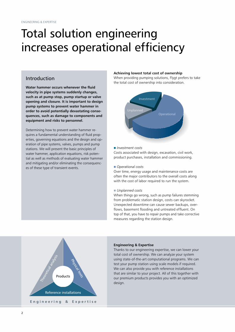
Investment costsCosts associated with design, excavation, civil work, product purchases, installation and commissioning.
Operational costsOver time, energy usage and maintenance costs are often the major contributors to the overall costs along with the cost of labor required to run the system.
Unplanned costsWhen things go wrong, such as pump failures stemming from problematic station design, costs can sky rocket. Unexpected downtime can cause sewer backups, over-flows, basement flooding and untreated effluent. On top of that, you have to repair pumps and take corrective measures regarding the station design.
When providing pumping solutions, Flygt prefers to take the total cost of ownership into consideration.
Engineering & Expertisethanks to our engineering expertise, we can lower your total cost of ownership. We can analyze your system using state-of-the-art computational programs. We can test your pump station using scale models if required. We can also provide you with reference installations that are similar to your project. All of this together with our premium products provides you with an optimized design.
3
Hydraulic transient analysis: Preventing water hammer
intrODUCtiOn
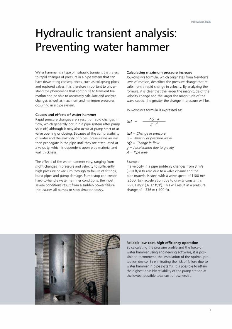
Reliable low-cost, high-efficiency operationBy calculating the pressure profile and the force of water hammer using engineering software, it is pos-sible to recommend the installation of the optimal pro-tection device. By eliminating the risk of failure due to water hammer in pipe systems, it is possible to attain the highest possible reliability of the pump station at the lowest possible total cost of ownership.
Water hammer is a type of hydraulic transient that refers to rapid changes of pressure in a pipe system that can have devastating consequences, such as collapsing pipes and ruptured valves. it is therefore important to under-stand the phenomena that contribute to transient for-mation and be able to accurately calculate and analyze changes as well as maximum and minimum pressures occurring in a pipe system.
Causes and effects of water hammerrapid pressure changes are a result of rapid changes in flow, which generally occur in a pipe system after pump shut-off, although it may also occur at pump start or at valve opening or closing. Because of the compressibility of water and the elasticity of pipes, pressure waves will then propagate in the pipe until they are attenuated at a velocity, which is dependent upon pipe material and wall thickness.
the effects of the water hammer vary, ranging from slight changes in pressure and velocity to sufficiently high pressure or vacuum through to failure of fittings, burst pipes and pump damage. pump stop can create hard-to-handle water hammer conditions; the most severe conditions result from a sudden power failure that causes all pumps to stop simultaneously.
Calculating maximum pressure increaseJoukowsky’s formula, which originates from newton’s laws of motion, describes the pressure change that re-sults from a rapid change in velocity. By analyzing the formula, it is clear that the larger the magnitude of the velocity change and the larger the magnitude of the wave speed, the greater the change in pressure will be.
Joukowsky’s formula is expressed as:
∆H = Change in pressurea = Velocity of pressure wave∆Q = Change in flowg = Acceleration due to gravityA = Pipe area
Exampleif a velocity in a pipe suddenly changes from 3 m/s (~10 ft/s) to zero due to a valve closure and the pipe material is steel with a wave speed of 1100 m/s (3600 ft/s), acceleration due to gravity constant is ~9.81 m/s2 (32.17 ft/s2). this will result in a pressure change of ~336 m (1100 ft).
∆H = ∆Q·ag·A

4
Factors that affect the consequences of water hammer
The different maximum subpressures due to different pipe profiles.
DEsign COnDitiOns
While it is difficult to determine when the risk of water hammer exists and calculations are required, there are several factors that generally indicate when taking pre-cautions against water hammer is advisable.
Pipeline profile the minimum pressure line (green profile in graph below) depends upon various factors such as the wave speed and the pump’s moment of inertia. therefore the minimum pressure line will retain the same shape regardless of the pipeline profile (dark blue profiles) as long as no vapor-ization occurs. the magnitude of the subpressure that the pipe will experience will therefore depend on the pipeline profile, i.e., the distance between the minimum pressure line and the pipeline profile (see graph).
Pipeline length pipe length will influence the reflection time and the inertia of water inside the pipe. the longer the pipe is, the longer the reflection time, that is, the time it takes for the wave to reflect at the outlet and return to the starting point. in addition, the longer the pipe, the larger the mass of water that will affect the moment of inertia of the water column. generally speaking, whenever the pipe length is greater than 300 m (985 ft) in length, the risk of subpressures exists and water hammer calcula-tions should be conducted.
5
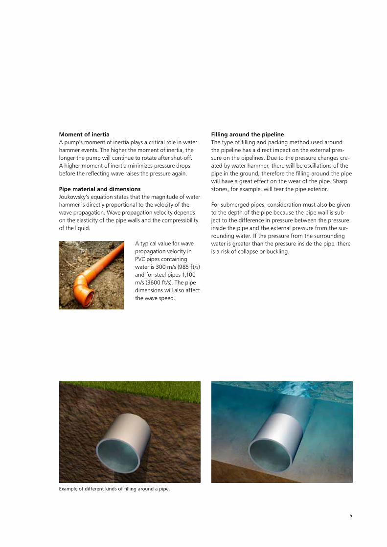
Example of different kinds of filling around a pipe.
Moment of inertiaA pump’s moment of inertia plays a critical role in water hammer events. the higher the moment of inertia, the longer the pump will continue to rotate after shut-off. A higher moment of inertia minimizes pressure drops before the reflecting wave raises the pressure again.
Pipe material and dimensionsJoukowsky’s equation states that the magnitude of water hammer is directly proportional to the velocity of the wave propagation. Wave propagation velocity depends on the elasticity of the pipe walls and the compressibility of the liquid.
Filling around the pipelinethe type of filling and packing method used around the pipeline has a direct impact on the external pres-sure on the pipelines. Due to the pressure changes cre-ated by water hammer, there will be oscillations of the pipe in the ground, therefore the filling around the pipe will have a great effect on the wear of the pipe. sharp stones, for example, will tear the pipe exterior.
For submerged pipes, consideration must also be given to the depth of the pipe because the pipe wall is sub-ject to the difference in pressure between the pressure inside the pipe and the external pressure from the sur-rounding water. if the pressure from the surrounding water is greater than the pressure inside the pipe, there is a risk of collapse or buckling.
A typical value for wave propagation velocity in pVC pipes containing water is 300 m/s (985 ft/s) and for steel pipes 1,100 m/s (3600 ft/s). the pipe dimensions will also affect the wave speed.
6
Consequences of water hammer
WAtEr hAmmEr EFFECts
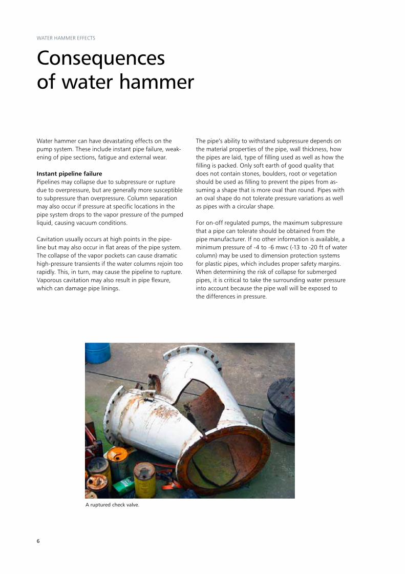
A ruptured check valve.
Water hammer can have devastating effects on the pump system. these include instant pipe failure, weak-ening of pipe sections, fatigue and external wear.
Instant pipeline failurepipelines may collapse due to subpressure or rupture due to overpressure, but are generally more susceptible to subpressure than overpressure. Column separation may also occur if pressure at specific locations in the pipe system drops to the vapor pressure of the pumped liquid, causing vacuum conditions.
Cavitation usually occurs at high points in the pipe-line but may also occur in flat areas of the pipe system. the collapse of the vapor pockets can cause dramatic high-pressure transients if the water columns rejoin too rapidly. this, in turn, may cause the pipeline to rupture. Vaporous cavitation may also result in pipe flexure, which can damage pipe linings.
the pipe’s ability to withstand subpressure depends on the material properties of the pipe, wall thickness, how the pipes are laid, type of filling used as well as how the filling is packed. Only soft earth of good quality that does not contain stones, boulders, root or vegetation should be used as filling to prevent the pipes from as-suming a shape that is more oval than round. pipes with an oval shape do not tolerate pressure variations as well as pipes with a circular shape.
For on-off regulated pumps, the maximum subpressure that a pipe can tolerate should be obtained from the pipe manufacturer. if no other information is available, a minimum pressure of -4 to -6 mwc (-13 to -20 ft of water column) may be used to dimension protection systems for plastic pipes, which includes proper safety margins. When determining the risk of collapse for submerged pipes, it is critical to take the surrounding water pressure into account because the pipe wall will be exposed to the differences in pressure.

7
Different effects of a weakened section.
Weakened pipeline sectionpipe failure can also occur after a period of time due to a weakened pipeline section. the cause of the weak-ened section may be corrosion, erosion due to flow or cavitation implosion. regardless of cause, the weakened section is sensitive to water hammer, which can lead to upsurge, downsurge, cracking or rupture.
Fatigue and external wearpipe fatigue and external wear are also common oc-currences. Axial pipe movement due to water hammer causes wear on the pipe, especially in a pump system with frequent starts and stops. most pipeline materi-als are more sensitive to fatigue due to subpressure rather than overpressure, and pipe fatigue is more pro-nounced when using plastic pipes. Dimensioning of subpressure depends largely on the pipe material and wall thickness and therefore this should be obtained from the pipe manufacturer.
Slamming valvesslamming valves are often misunderstood to be caused by water hammer, but this is generally not the case. instead slamming valves are typically the cause of very high water column occuring at pump stop. When the pump is stopped, the water decelerates and reverses direction. A fast water column retardation is often gen-erated in systems where we do not have problems with water hammer. typically slamming valves can be seen in a system with a short pipe length and a relatively high static head while water hammer typically appears in systems with long pipe length and small static head. A high head and a short pipe length will cause a high water column deceleration. Calculations to predict the possibility of a slamming valve can be done manually; however, to be more precise, the use of water hammer calculation software is recommended.
Weakened section Downsurge
Cracking rupture
Upsurge
8
prOtECtiOn mEthODs
When selecting the appropriate method of protec-tion for a pipe system, it is important to consider vari-ous factors, such as the number of pumps in opera-tion, conditions during normal stop and power failure as well as the risk of buckling, fatigue and clogging. it is critical that the protection method used is based on thorough understanding of the effect that the method will have on the system and that the protection method is dimensioned accordingly on a case-by-case basis. protection equipment can be divided in two groups: active protection and passive protection.
Devices used to actively protect the pump station against the effects of water hammer are dependent upon power supply. therefore these methods only pro-tect the pipeline during normal pump stops. Examples of active protection include variable frequency drives, soft starters and slow-closing valves.
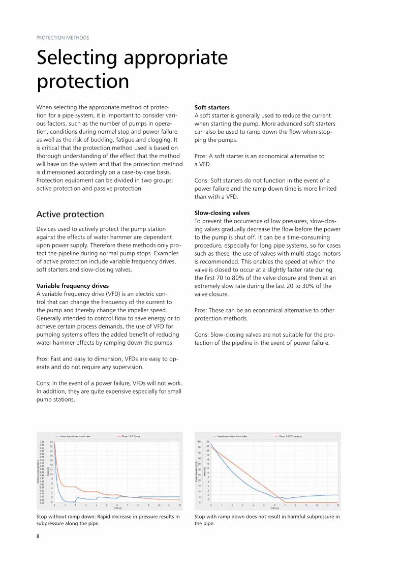
Variable frequency drivesA variable frequency drive (VFD) is an electric con-trol that can change the frequency of the current to the pump and thereby change the impeller speed. generally intended to control flow to save energy or to achieve certain process demands, the use of VFD for pumping systems offers the added benefit of reducing water hammer effects by ramping down the pumps.
pros: Fast and easy to dimension, VFDs are easy to op-erate and do not require any supervision.
Cons: in the event of a power failure, VFDs will not work. in addition, they are quite expensive especially for small pump stations.
Soft startersA soft starter is generally used to reduce the current when starting the pump. more advanced soft starters can also be used to ramp down the flow when stop-ping the pumps.
pros: A soft starter is an economical alternative to a VFD.
Cons: soft starters do not function in the event of a power failure and the ramp down time is more limited than with a VFD.
Slow-closing valvesto prevent the occurrence of low pressures, slow-clos-ing valves gradually decrease the flow before the power to the pump is shut off. it can be a time-consuming procedure, especially for long pipe systems, so for cases such as these, the use of valves with multi-stage motors is recommended. this enables the speed at which the valve is closed to occur at a slightly faster rate during the first 70 to 80% of the valve closure and then at an extremely slow rate during the last 20 to 30% of the valve closure.
pros: these can be an economical alternative to other protection methods.
Cons: slow-closing valves are not suitable for the pro-tection of the pipeline in the event of power failure.
Selecting appropriate protection
Active protection
Stop without ramp down: Rapid decrease in pressure results in subpressure along the pipe.
Stop with ramp down does not result in harmful subpressure in the pipe.

9
Passive protection
passive protection equipment operates without the need for additional power supply and can therefore be used to protect the pipe system in the event of a power failure. Air chambers, surge towers and air inlet/release valves are methods used to provide passive protection.
Air chambersStandard air chamberAn air chamber is a reservoir, connected to the pipeline, which is filled with liquid and compressed air. When the pressure drops after a pump stop, liquid from the air chamber is discharged into the pipe system thereby slowly decelerating the flow and preventing low pressures.
Surge towerthis open tower or tank contains water connect-ed to the force main and is used to reduce sub-pressures that occur in pipe systems. it essen-tially functions like an air chamber except that the tower is open to atmo-spheric pressure and the potential energy is stored in the height of the water column rather than in the pressurized air. At pump stoppage, the pressure in the pipes decreases and the surge tower releases water into the force main to compensate for the low pressure.
pros: the method is maintenance free and provides pro-tection in the event of a power failure.
Cons: tower height must be higher than the total dy-namic head when all pumps are operating, which can be expensive.
Air inlet valves or release valvesAir inlet valves, or release valves, are mounted along the pipelines at locations where subpressure occurs. the valves permit air to enter the pipe when the pressure in the pipe falls below a pre-set value. to prevent the formation of air pockets at the highest elevations in the pipe system, this air must then be evacuated through an air release valve. if the air is released too quickly, the liquid column forcing the air out of the system can gain velocity. Once all the air is discharged and the liquid column abruptly stops, high pressure can arise.
pros: the installation costs can, in some cases, be more economical.
Cons: Undesirable odors, clogging and the potential separation of water columns. it is important to com-pletely purge all of the air out of the system since any air trapped in the system consumes a considerable amount of energy.
A large air chamber installation protecting the pipe system.
Surge tower in a propeller pump system protecting 2,000 m (6,562 ft), of pipes.
pros: this is a reliable, almost maintenance-free method, which also operates in the event of a power failure.
Cons: Valve slamming can result from an air cham-ber that is connected too closely to pumps and check valves. in addition, if a large chamber is required, an air chamber can be expensive. the air also needs to be re-charged periodically.
Bladder air chamberBladder air chamber works like an air chamber but con-tains a bladder with compressed air inside. the blad-der is airtight, which prevents air from mixing with the liquid. For ease of installation, pressure in the bladder can be factory pre-charged.
pros: the method is maintenance free and provides pro-tection in the event of a power failure.
Cons: if a large air chamber is required, it can be expensive.
10
Calculation methods
to calculate fluid transients, the Flygt Engineering tool uses the same state-of-the-art methods used for most commercial software. Our software employs the transient equations that are derived from two governing equations: the equation of motion and the continuity equation. For computational calculations, these equations must be transformed into a set of finite-difference equations. to fix boundary conditions, the Flygt Engineering tool uses the method of characteristics and applies them to these finite-difference equations.
Determining the effects of water hammer
trAnsiEnt AnAlysis & tEsting
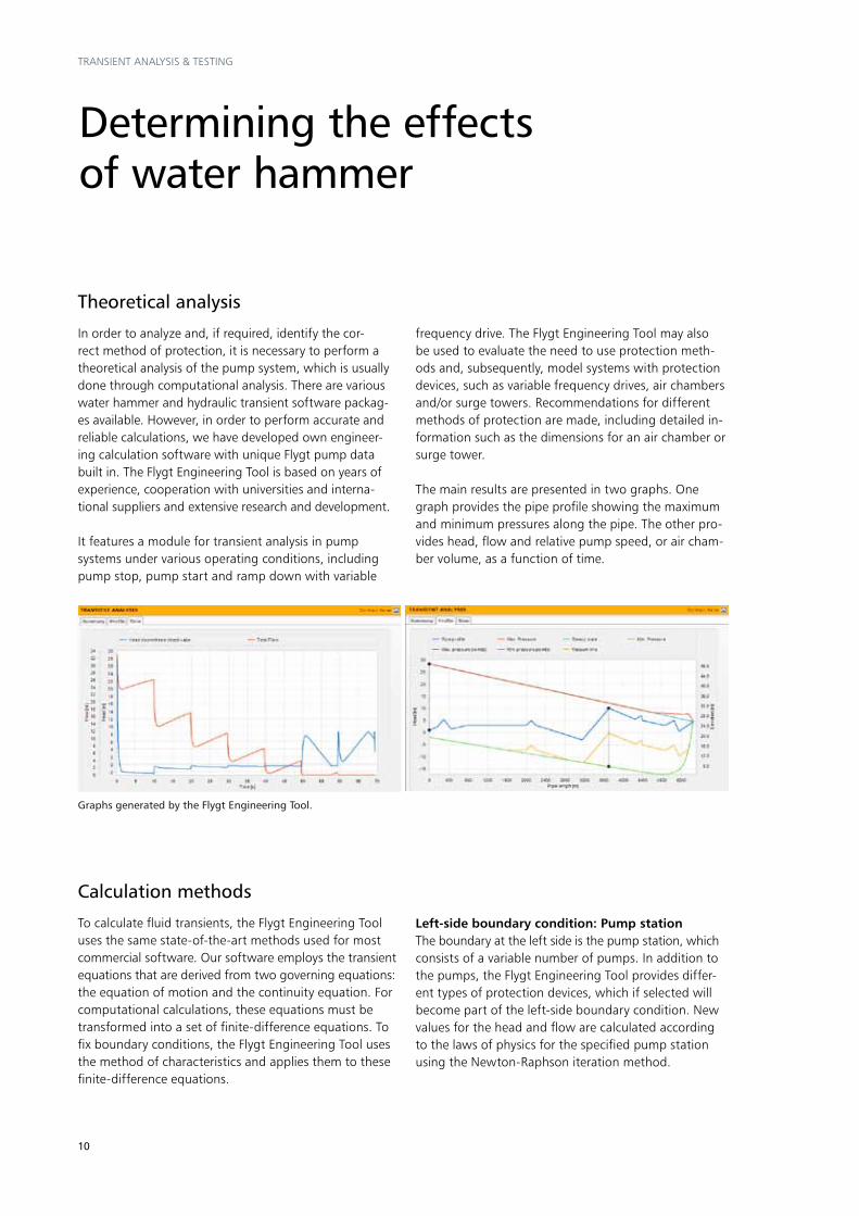
in order to analyze and, if required, identify the cor-rect method of protection, it is necessary to perform a theoretical analysis of the pump system, which is usually done through computational analysis. there are various water hammer and hydraulic transient software packag-es available. however, in order to perform accurate and reliable calculations, we have developed own engineer-ing calculation software with unique Flygt pump data built in. the Flygt Engineering tool is based on years of experience, cooperation with universities and interna-tional suppliers and extensive research and development.
it features a module for transient analysis in pump systems under various operating conditions, including pump stop, pump start and ramp down with variable
Graphs generated by the Flygt Engineering Tool.
Theoretical analysis
frequency drive. the Flygt Engineering tool may also be used to evaluate the need to use protection meth-ods and, subsequently, model systems with protection devices, such as variable frequency drives, air chambers and/or surge towers. recommendations for different methods of protection are made, including detailed in-formation such as the dimensions for an air chamber or surge tower.
the main results are presented in two graphs. One graph provides the pipe profile showing the maximum and minimum pressures along the pipe. the other pro-vides head, flow and relative pump speed, or air cham-ber volume, as a function of time.
Left-side boundary condition: Pump stationthe boundary at the left side is the pump station, which consists of a variable number of pumps. in addition to the pumps, the Flygt Engineering tool provides differ-ent types of protection devices, which if selected will become part of the left-side boundary condition. new values for the head and flow are calculated according to the laws of physics for the specified pump station using the newton-raphson iteration method.

11
Physical testing
Flygt conducts extensive physical hydraulic testing in our laboratories, which contributes to a thorough un-derstanding of fluids dynamics and system engineering know-how. While other transient calculation software uses general data, the Flygt Engineering tool uses ac-curately measured data from specific pump models to calculate transient effects in its water hammer module. testing of Flygt pumps is detailed and recorded in all operating modes, thereby making it possible to repre-sent all pumps in various modes of operation on the four-quadrant diagram. this provides accurately mea-sured data that is used in the calculations for the Flygt Engineering tool.
One of the test setups used to measure four-quadrant data.
normal pump mode
Energy to heat
Impeller speed, rpm
Flow
Energy to heat
Energy to heat
reverse turbine
reverse pump
Energy to heat
normal turbine mode
Right-side boundary condition: Outletthe Flygt Engineering tool enables the right-side bound-ary condition to be selected either as a submerged outlet or as a free outlet. if the submerged outlet condition is selected, the right-side boundary will have the water level over the submerged outlet as pressure. if the free outlet condition is selected, the boundary will have atmospheric pressure.
Pump operationWhen stopping a pump in a long pipe system, the pump will go through different modes of operation. Knowledge of the complete pump operation is essential in order to perform accurate water hammer calculations. the illustration here describes the different modes created by the change in impeller speed and the flow when the pump is operating under normal rotation and reverse ro-tation. Accurate measurement of this data is important in order to be able to achieve accurate calculations.

12
Proven worldwide
Sweden: Pump station
ChallengeOne of stockholm’s main pump stations, which handled major volumes of sewage water, required upgrading. Originally installed in 1930, the double-suction pump in-stallation, including equipment and a 1200 mm (47") pres-sure pipe to the treatment plant, was prone to failure and unplanned stops, causing flooding into the Baltic sea.
Solutionto safeguard the swedish capital’s well-deserved reputa-tion for clean water, the city of stockholm selected us to upgrade the original pump station to a Flygt pump station.
Four new pumps were installed to replace the existing three and the maximum flow from the station increased by 59 percent, from 2.2 m3/s to 3.5 m3/s (35,000 to 55,000 Us gpm). the 1,200 mm (47") pipe underwent major renovation and a second parallel pipe of 900 mm (35") was installed. Due to a small storage volume, the pumps required speed regulation. During rainy periods when flow is high, three to four pumps transport waste-water into both pressure pipes. During dry weather con-ditions, the daytime flow varies between 0.7 and 1 m3/s (11,000 and 17,000 Us gpm) and the 1,200 mm (47") pipe is used; at night, the flow rate is between 0 and 0.7 m3/s (11,000 Us gpm) and the 900 mm (35") pipe is used.
Flygt has performed water hammer analysis on thousands of installations around the world and has recommended and dimensioned protection methods. Engineering expertise and years of experi-ence have resulted in the success of these installations. two such cases are described below.
rEFErEnCE instAllAtiOns
to prevent harmful transient effects such as water hammer during pump stop from occurring in the pipe-line, a feed pipe connected to lake mälaren just west of the city has been installed. the feed pipe is equipped with check valves; if there is subpressure in the pipeline after the pumps, lake water will be fed into the system.
An air chamber, surge tower and air inlet valves are normally used to prevent water hammer problems at pump stop – whether a planned stop or in the event of a power failure. in the inlet pipes of the Flygt pump station have check valves installed from the lake side at a position above the lake’s maximum water level right after the pumps. in case of any low pressure after the pump, the check valves will open and the lake will work as a surge tower with an infinite volume.
Layout of the surge pipes to prevent water hammer.
13
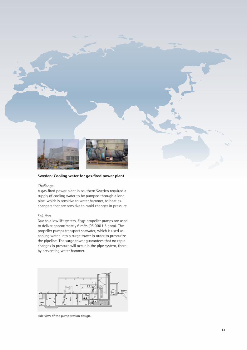
Sweden: Cooling water for gas-fired power plant
ChallengeA gas-fired power plant in southern sweden required a supply of cooling water to be pumped through a long pipe, which is sensitive to water hammer, to heat ex-changers that are sensitive to rapid changes in pressure.
SolutionDue to a low lift system, Flygt propeller pumps are used to deliver approximately 6 m³/s (95,000 Us gpm). the propeller pumps transport seawater, which is used as cooling water, into a surge tower in order to pressurize the pipeline. the surge tower guarantees that no rapid changes in pressure will occur in the pipe system, there-by preventing water hammer.
Side view of the pump station design.

14
sErViCEs AnD sUppOrt
Engineering & Expertise
Theoretical analysis
Design tools
When you design pump stations, we can offer ad-vanced engineering tools to generate sump designs. Our design recommendations give you essential in-formation regarding dimensions and layout. in short, we assist you every step of the way to make sure you optimize performance and achieve energy-efficient operations.
To ensure reliable and highly efficient operation, we offer comprehensive support and service for pump station design, system analysis, installation, commissioning, operation and maintenance.
Computational fluid dynamics (CFD) can provide far more detailed information about the flow field in a frac-tion of the time required to get the same information through physical hydraulic scale model testing. Using CFD in combination with computer-aided design (CAD) tools, it is possible to obtain a more efficient method of numerical simulation for pump station design.
to obtain a reliable, energy-efficient pumping system, it is important to analyze all modes of operation. to analyze the transient effects at pump start and stop with respect to flow and head as well as the electrical parameters such as current and torque, it is also im-portant to have an accurate mathematical description of the pump and motor, which is gained, in part, from extensive testing in our laboratories.

Theo
retic
al a
naly
sis
Products
Reference installations
Physical tests
E n g i n e e r i n g & E x p e r t i s e
15
Physical testing
physical hydraulic scale model testing can provide reli-able, cost-effective solutions to complex hydraulic prob-lems. this is particularly true for pump stations in which the geometry departs from recommended standards or where no prior experience with the application exists. scale model testing can also be employed to identify solutions for existing installations and has proven to be a far less expensive way to determine the viability of pos-sible solutions than through trial and error at full scale.
When our standard design recommendations are not met, we can assist in determining the need for physi-cal testing as well as planning and arranging the testing and evaluating the results.
model test photos courtesy of hydrotec Consultants ltd.
We have conducted system analysis and designed pump stations for thousands of installations around the world. Engineering expertise and years of experience gained from the design and operation of these installations have been a critical success factor when analyzing, testing and commissioning new pump installations.
Reference installations

ITT Water & Wastewater ABSE–174 87 SundbybergVisiting address:Gesällvägen 33Tel +46–8–475 60 00Fax +46–8–475 69 00
itt is a global provider of water handling and treatment solutions for municipal and industrial customers in more than 140 countries. the company designs and delivers energy-efficient solutions and related services for water and wastewater transport, biological treatment, filtra-tion, and disinfection through five global brands – Flygt, godwin pumps, leopold, sanitaire and Wedeco.
the company maintains the industry’s most extensive sales and service organization, oper ating both locally and globally to meet the needs of customers. And by combining its world-class products and engineering expertise, itt can offer integrated and multi-discipline solutions including full process design, equipment selection and supply, installation, commissioning and operator training.
to learn more, please visit the company’s website: http://www.ittwww.com/.
1209
. tr
ansi
ent
Ana
lysi
s . 1
. m
aste
r . 1
. 20
1102
16