—engineering data — bosch · pdf filerequirements. i optimum viscosity at i...
TRANSCRIPT
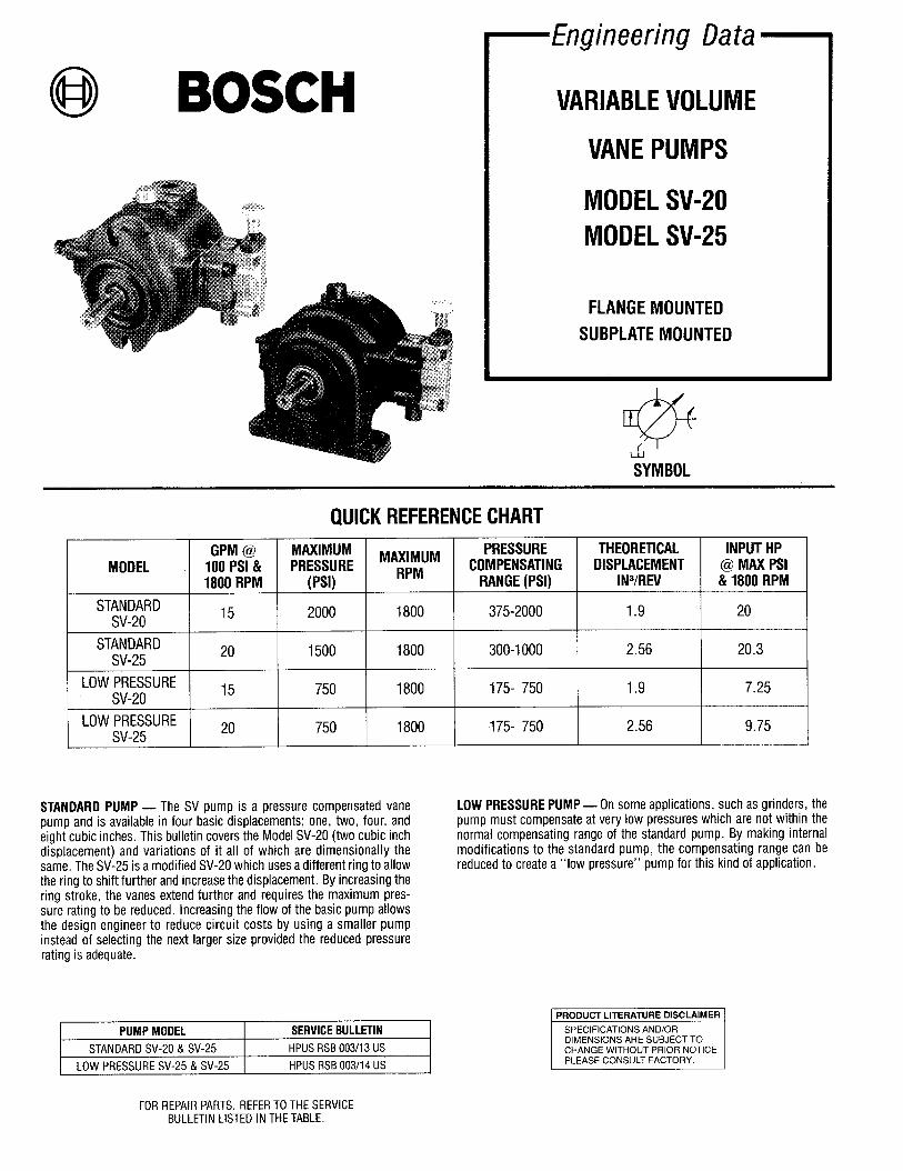
@ BOSCH—Engineering Data —
VARIABLE VOLUME
VANE PUMPS
MODEL SV-20MODEL SV-25
FLANGE MOUNTED
SUBPLATE MOUNTED
@ (
SYMBOL
SV-20
SV-25
SV-20
LOW PRESSURE *OSV-25
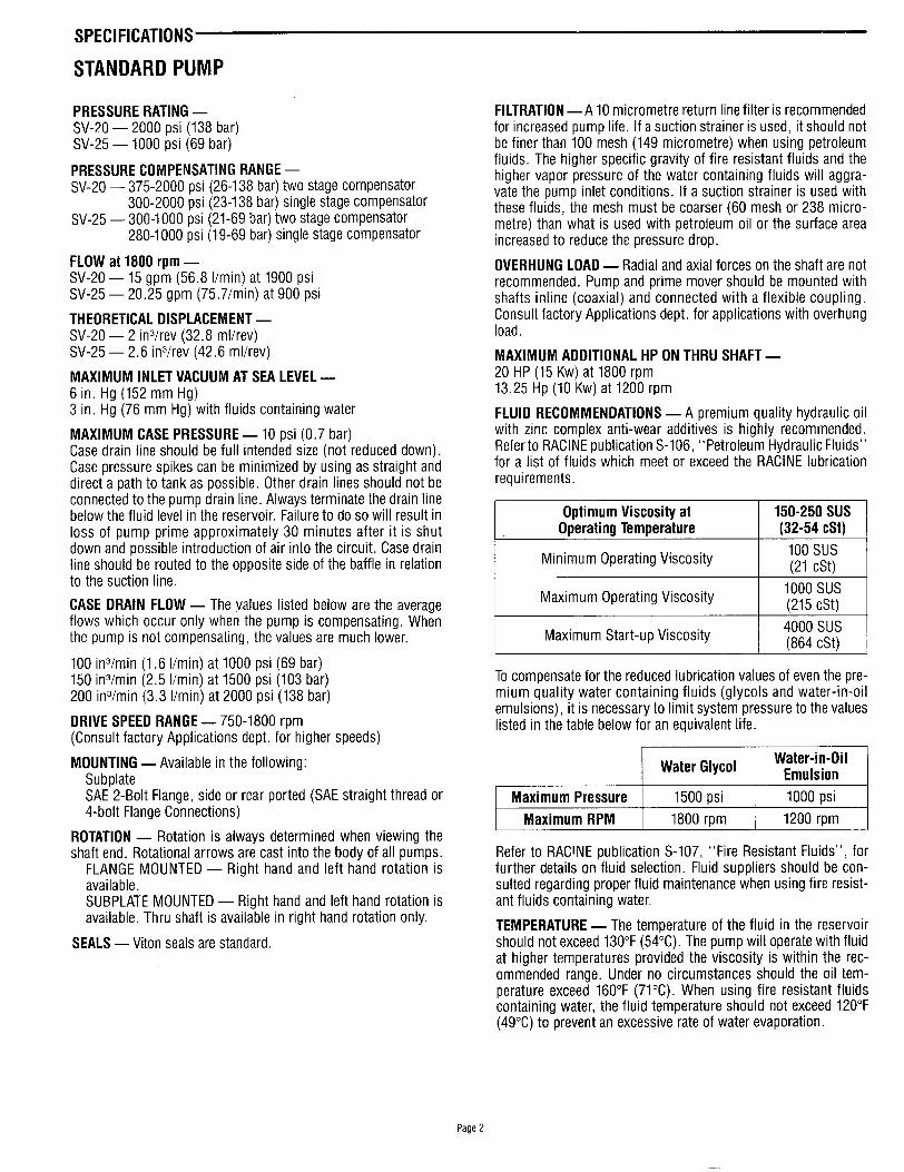
QUICK REFERENCECHART
MAXIMUMPRESSURE
(Psi)
2000
1500
750
750
MAXIMUMRPM
1800
1800
1800
1800
PRESSURECOMPENSATING
RANGE (PSI)
375-2000
300-1000
175-750
175-750
1.9 I 20
2.56 I 9.75
STANDARD PUMP — The SV r)umD is a Dressure compensated vane LOW PRESSURE PUMP — On some applications, such as grinders, thepump and is available in four basic displacements; one, two, four, and pump must compensate at very low pressures which are not within theeight cubic inches. This bulletin covers the ModeI SV-20 (two cubic inch normal compensating range of the standard pump. By making internal
displacement) and variations of it all of which are dimensionally the modifications to the standard pump, the compensating range can besame. The SV-25 is a modified SV-20 which uses a different ring to allow reduced to create a‘ ‘low pressure” pump for this kind of application.the ring to shift further and increase the displacement. By increasing thering stroke, the vanes extend further and requires the maximum pres-sure rating to be reduced. Increasing the flow of the basic pump allowsthe design engineer to reduce circuit costs by using a smaller pumpinstead of selecting the next larger size provided the reduced pressurerating is adequate.
[ PRODUCT LITERATURE DISCLAIMER ~
I SPECIFICATIONS AND/OR I
SV-20 &SV-25 HPUS RSB 003/13 US I DIMENSIONS ARE SUBJECT TOCHANGE WITHOUT PRIOR NOTICE.
SV-25 &SV-25 HPUS RSB 003/14 US I PLEASE CONSULT FACTORY. I
FOR REPAIR PARTS, REFER TO THE SERVICEBULLETIN LISTED IN THE TABLE.
STANDARD PUMP
PRESSURE RATING —SV-20 — 2000 psi (138 bar)SV-25 — 1000 psi (69 bar)
PRESSURE COMPENSATING RANGE —SV-20 — 375-2000 psi (26-138 bar) two stage compensator
300-2000 psi (23-1 38 bar) single stage compensatorSV-25 — 300-1000 psi (21-69 bar) two stage compensator
280-1000 psi (19-69 bar) single stage compensator
FLOW at 1800 rpm —SV-20 — 15 gpm (56.8 l/rein) at 1900 psiSV-25 — 20.25 gpm (75,7/rein) at 900 psi
THEORETICAL DISPLACEMENT —SV-20 — 2 in3/rev (32.8 ml/rev)SV-25 — 2.6 in3/rev (42,6 ml/rev)
MAXIMUM INLET VACUUM AT SEA LEVEL —6 in. Hg (152 mm Hg)3 in. Hg (76 mm Hg) with fluids containing water
MAXIMUM CASE PRESSURE — 10 psi (0.7 bar)Case drain line should be full intended size (not reduced down).Case pressure spikes can be minimized by using as straight anddirect a path to tank as possible. Other drain lines should not beconnected to the pump drain line. Always terminate the drain linebelow the fluid level in the reservoir. Failure to do so will result inloss of pump prime approximately 30 minutes after it is shutdown and possible introduction of air into the circuit. Case drainline should be routed to the opposite side of the baffle in relationto the suction line.
CASE DRAIN FLOW — The values listed below are the averageflows which occur only when the pump is compensating. Whenthe pump is not compensating, the values are much lower.
100 in3/min (1.6 l/rein) at 1000 psi (69 bar)150 in3/min (2.5 l/rein) at 1500 psi (103 bar)200 in3/min (3.3 l/rein) at 2000 psi (138 bar)
DRIVE SPEED RANGE — 750-1800 rpm(Consult factory Applications dept. for higher speeds)
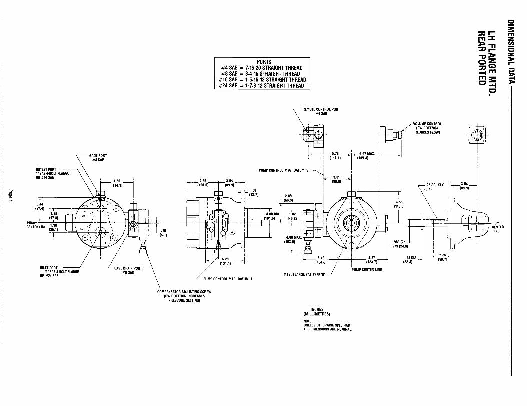
MOUNTING — Available in the following:SubplateSAE 2-Bolt Flange, side or rear ported (SAE straight thread or4-bolt Flange Connections)
ROTATION — Rotation is always determined when viewing theshaft end. Rotational arrows are cast into the body of all pumps.
FLANGE MOUNTED — Right hand and left hand rotation isavailable.SUBPLATE MOUNTED — Right hand and left hand rotation isavailable. Thru shaft is available in right hand rotation only.
SEALS — Viton seals are standard.
FILTRATION —A 10 micrometre return line filter is recommendedfor increased pump life. If a suction strainer is used, it should notbe finer than 100 mesh (149 micrometre) when using petroleumfluids. The higher specific gravity of fire resistant fluids and thehigher vapor pressure of the water containing fluids will aggra-vate the pump inlet conditions. If a suction strainer is used withthese fluids, the mesh must be coarser (60 mesh or 238 micro-metre) than what is used with petroleum oil or the surface areaincreased to reduce the pressure drop.
OVERHUNG LOAD — Radial and axial forces on the shaft are notrecommended. Pump and prime mover should be mounted withshafts inline (coaxial) and connected with a flexible coupling.Consult factory Applications dept. for applications with overhungload.
MAXIMUM ADDITIONAL HP ON THRU SHAFT —20 HP (15 Kw) at 1800 rpm13.25 Hp (10 Kw) at 1200 rpm
FLUID RECOMMENDATIONS — A premium quality hydraulic oilwith zinc complex anti-wear additives is highly recommended.Refer to RACINE publication S-106, “Petroleum Hydraulic Fluids”for a list of fluids which meet or exceed the RACINE lubricationrequirements.
I Optimum Viscosity at I 150-250 SUSOperating Temperature (32-54 cSt) I
I Minimum Operating Viscosity I100Sus(21 Cst) I
I Maximum Operating Viscosity I 1000 Sus(215 cSt) I
I Maximum Start-up Viscosity I4000 Sus(864 cSt) I
To compensate for the reduced lubrication values of even the pre-mium quality water containing fluids (glycols and water-in-oilemulsions), it is necessary to limit system pressure to the valueslisted in the table below for an equivalent life.
Refer to RACINE publication S-107, “Fire Resistant Fluids”, forfurther details on fluid selection. Fluid suppliers should be con-sulted regarding proper fluid maintenance when using fire resist-ant fluids containing water.
TEMPERATURE — The temperature of the fluid in the reservoirshould not exceed 130”F (54°C). The pump will operate with fluidat higher temperatures provided the viscosity is within the rec-ommended range. Under no circumstances should the oil tem-perature exceed 160”F (71°C). When using fire resistant fluidscontaining water, the fluid temperature should not exceed 121YF(49°C) to prevent an excessive rate of water evaporation.
Page 2
SPECIFICATIONS
SCREW VOLUME CONTROL — The screw volume control is anadjustable stop which is used to reduce the maximum pump flowand is optional. Turning clockwise will reduce the flow in directproportion to the displacement of the adjusting screw. During ini-tial start-up, the flow setting should beat least 300/. of the max-imum pump flow.
SV-20 — 1/4 turn (90°) clockwise will reduce the flow approx-imately 2.2 gpm (8.3 l/rein) when the pump is driven at 1800rpm.SV-25 — 1/4 turn (90°) clockwise will reduce the flow approx-imately 2.9 gpm (11 l/rein) when the pump is driven at 1800rpm.
When a volume control is used to reduce the maximum flow ofthe pump, the horsepower required to drive the pump is alsoreduced. To determine the input H? use the following formula:
Input = gpm x psiHP 1714
+ Deadhead HP at the compensator setting
MOUNTING POSITION — Unrestricted. Caution must be exer-cised.with vertical mounting to prevent the weight or end thrustof the prime mover from being applied to the pump shaft.
SHAFT ALIGNMENT — Shaft alignment should be within 0.003total indicator reading. If the shafts are not properly aligned,
increased mechanical noise from the unit will result.
START-UP- To insure priming on initial start-up, air in thepump and inlet line must be allowed to escape. If the pump outletis normally blocked, it must be temporarily vented. This can beaccomplished by opening the valve, temporarily cracking a fitting,or installing an air bleed valve (refer to Bulletin J-34).
CONTROL OPTIONS — Many energy saving controls are availablein addition to the standard two-stage pressure compensator.Refer to Bulletin A-n for performance and dimensional data.
COMBINATION MOUNTING — To simplify multi-pump circuits,adaptor kits are available to mount additional pumps in combi-nation on the rear cover of the flange mounted (side ported)pumps. Refer to Bulletin A-14 for horsepower limitations, adap-tors available, dimensional data and How-To-Order.
WEIGHT (Approximate) —Subplate Mounted Pump . . . . . . . . . . . . . ...65 Ibs. (29.5 Kg)Flange Mounted Pump . . . . . . . . . . . . . . . . ..701 bs. (31.8 Kg)Add for Screw Volume Control . . . . . . . . . . . . . . 1 Ibs. (0,5 Kg)Add for Thru Shaft . . . . . . . . . . . . . . . . . . . . . . . 1 Ibs. (0.5 Kg)
LOW PRESSURE PUMPNOTE: All of the specifications for the standard pump also pertainto the low pressure pump except those listed below.
PRESSURE RATING — CASE DRAIN FLOW— 210 in3/min (3.4 l/rein) is the average flow
SV-20 — 750 psi (52 bar) which will occur when the pump is compensating at 750 psi
SV-25 — 750 ~si (52 bar) (52 bar). When the pump is not compensating, the value is much,.lower.
PRESSURE COMPENSATING RANGE —SV-20 — 175-750 psi (12-52 bar) ROTATION — Right hand only. Clockwise when viewing shaft end.SV-25 — 175-750 psi (12-52 bar)
SEALS — Viton seals are standard.FLOW RATING AT 1800 rpm —SV-20 — 15 gpm (56.8 l/rein) at 650 psi (45 bar)
SCREW VOLUME CONTROL — The screw volume control is
SV-25 — 20 gpm (75.7 l/rein) at 650 psi (45 bar)standard.
Page 3
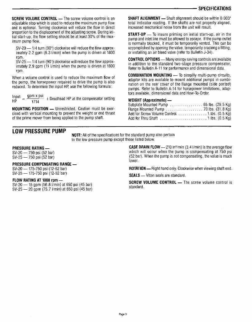
PERFORMANCE CHARACTERISTICS
STANDARD PUMP DATAPLOllED WITHOILAT12~F (49”C)VISCOSITY @ 12WF = 140 SUS (29.6 cSt)
SV-20 @ 1200 rpm
200 403 WI 8W 10XI 1200 1400 1600 1800 2009
OUTLETPRESSURE(P. S. l.)
SV-20 @ 1800 rpm
20
18
16 800
14 7C0
z
~ 12 6CQ&
=.3 —
:503 ~@ 10
s. %S8 4EQ gg
<
6 3Em
4 203
2 m
2c04c0fa181NlcM 1203 1400 1603 18Cfl 2LMI
OUTLETPRESSURE(P. S. 1.1
SV-25 @ 1200 rpm SV-25 @ 1800 rpm
22, ! 1 I I 1 I I I
OUTLH PRESSURE (PSI)
--- PRESSURE SPIKES LIMITEDTO 2500 PSI
Page 4
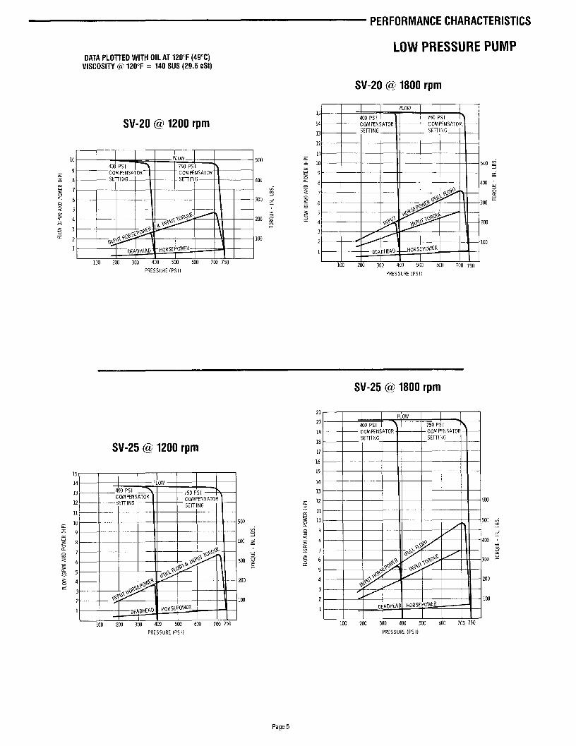
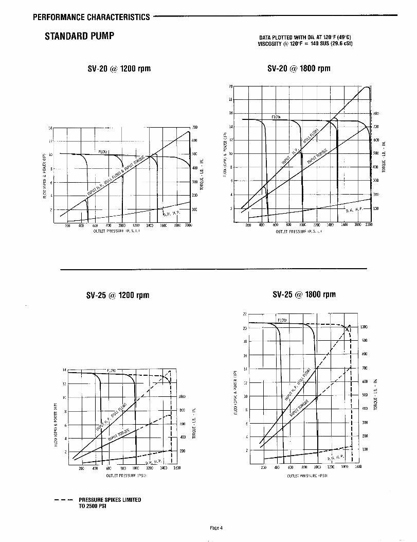
PERFORMANCE CHARACTERISTICS
LOW PRESSURE PUMPDATA PLOTTED WITH OIL AT 121TF (49”C)
VISCOSITY @ 120”F = 140 SUS (29.6 cst)
SV-20 @ 1800 rpm
SV-20 @ 1200 rpm
10 I - 500400 Ps I
9c=8 400
&,3 226 300 :~
—
5%4.g
2W ;
g3e
ti2 100
1I
100 200 3ot 400 500 600 7W 750
PRESSURE (PSI)
15
14
13
12
11
10 500 z“
9 ~“E, 4cm a
%o
~ z
g 6 300 +
200
100 2Lm 300 400 500 600 700 750
EiZE!!rPRESSURE (PSI)
SV-25 @ 1200 rpm
15
14
13 — 400 PSICOMFFNS ATOR \
12 — SETTINGCOMFtNSATO RSETTING
11 —
10! 50C
9 2J
8 400 g
7 3
6 300 zs
5
+. ml
i 1
II m
o} HORSEt’OwE~I I 1 I I
o 600 703 750~
100 50
SV-25 @ 1800 rpm
21FLoW
20 d400 PSI I A’ 750 Ps [
19 COMFINSATOR COMPINSATOR~ —
18SE~l NG SETTING
17
16 I15
14 1
13I
= 12 630g
115z= 10 IE
9;
s8
.2756
d5
4
3 /
2 A
1
ml 200 300 406 5Ln3 (00 7C0 750
PRESSURE (PSI) PRESSURE (PS 1)
Page 5
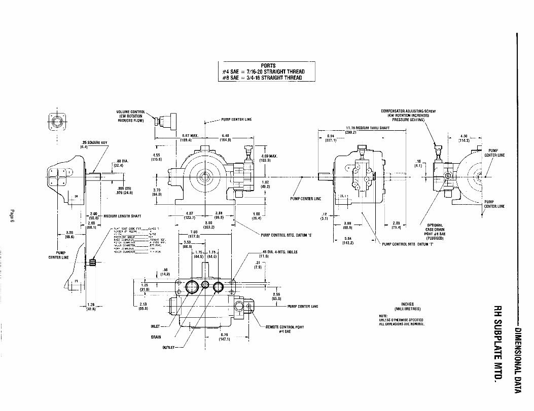
DIMENSIONAL
DATA
$&i.
RH
SUBPLATE
MTD
.
II
Page6

DIMENSIONAL
DATA
LHSU
BPLATEM
TD.
I-4--H
Page7

DIMENSIONAL
DATA
-+!!$F..++
Page8
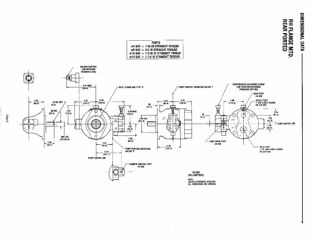
DIMENSIONAL
DATA
RH
FLANG
EM
TD.
REAR
POR
TED
II
1
11I
i—
+$ ++++rT
T7’-
%-L—
——
——
J——
---u4k=u----
Page9

IIII
IIII
&-
.++..\&l —
—.-.L
A3-t-l
LHFLAN
GE
MTD
.SID
EPO
RTED
Page10
L“I
1I
Page11
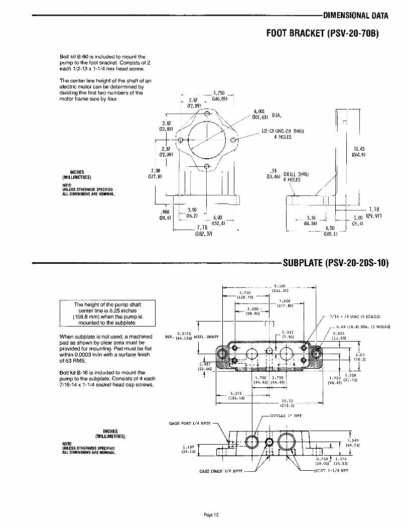
FOOT BRACKET (PSV-20-70B)
Bolt kit B-90 is included to mount thepump to the foot bracket. Consists of 2each 1/2-1 3 x 1-1/4 hex head screw.
The center line height of the shaft of anelectric motor can be determined bydividing the first two numbers of themotor frame size by four.
INCHES(MILLIMETRES)
NOTEUNLESSOTHERWISESPECIFIEDALL DIMENSIONSARE NOMINAL.
I
2.87(72.89)
m.7.03 /
(177.8)
L r! ,,,,,:; II(182.37)
THRU
mWhen subplate is not used, a machinedpad as shown by clear area must beprovided for mounting. Pad must be flatwithin 0.0003 infin with a surface finishof 63 RMS.
Bolt kit B-16 is included to mount thepump to the subplate. Consists of 4 each7/16-14 x 1-1/4 socket head cap screws.
INCHES(MILLIMETRES)
NOTEUNLESS OTHERWISESPECIFIEDALL DIMENSIONS ARE NOMINAL.
RSF.3.3125
(84.138)
i]
&(1;?6) ~~&:HRu
‘\,
;- !--,,,,,’! :~:
L
3.?4 J(24. 84)
6.50(165.1) —
L (241.30)
( :;:5:0) --+ I
i10.43
(264.9)
-d—— 1.18
1.00 (29. 97)!25.4)
(PSV-20-20S-10)
73.00
(76.2)
-1
t I 1.750 I ! 1.2501.750
1.750 (31.75)(44.45) (44.45) (44.4s)
I i- 1“ 4 I
I r,
OUTLET 1), NPT
GAGE PORT 1/4 NPTFT t
1.187(30.1s) II,
I(19.05) (34.93)
CASE DRAIN 3/8 NPTF INLET 1-1/4 NPT
Page 12

HOW TO ORDER
STANDARD PUMPPVSF-20HRM-52
I MOUNTINGS - SUBPLATEA - FLANGE, SIDE PORTED
(SAE STRAIGHT THREAD)B - FLANGE, REAR PORTEO
(SAE STRAIGHT THREAD)C - FLANGE, SIDE PORTED
(4 BOLT FLANGE CONNECTIONS)
R - FLANGE, REAR PORTED(4 BOLT FLANGE CONNECTIONS)
I VOLUME CONTROLN -NO VOLUME CONTROL
S - SCREW VOLUME CONTROL
CONTROL OPTIONS-STANDARD PRESSURE COMPENSATOR
*S -SOLENOIDTWO-PRESSURE (NORMALLYLOW, ENERGIZE FOR HIGH PRESSURE)
*H - SOLENOID TWO-PRESSURE (NORMALLYHIGH, ENERGIZE FOR LOW PRESSURE)
‘V - SOLENOID TWO-PRESSURE (NORMALLYVENTED, ENERGIZE FOR HIGH PRESSURE)
J - HYDRAULIC TWO-PRESSURE (NORMALLYLOW, ENERGIZE FOR HIGH PRESSURE)
L - LOAD SENSING
T - TORQUE LIMITINGK - SINGLE STAGE COMPENSATOR
“Indicate the desired solenoid voltage andfrequency at the end of the pump code.
To order the lock for the compensator adjustingscrew, specify “LOCK” at the end of the code.
~ ‘ESIGN DIGIT
L
-52 (SUBPLATE MOUNTED ONLY)
-62 (FLANGE MOUNTED ONLY)
SHAFTI
t M - KEYED SHAFT MEDIUM LENGTH
0- THRU SHAFT MEDIUM LENGTH(SUBPLATE MOUNTED ONLY)
ROTATION (VIEWING SHAFT END)
R - RIGHT HAND (CLOCKWISE)
L - LEFT HAND (COUNTERCLOCKWISE)
PRESSURE RATING.2000 Psl
E -1000 PSI (SV-25 ONLY)
FLOW20-15GPM ti( 1800 RPM
25-20 GPM @ 1800 RPM
SEALS
F - VITON
I SOLENOIDVOLTAGESAVAILABLE I
~
11 0/115 VAC 50/60 Hz (DUAL FREQUENCY)220/230 VAC 50/60 Hz (DUAL FREQUENCY)
FOR SOLENOIDS WITH QUICK CONNECT(HIRSCHMANN TYPE) CONSULT FACTORY
LOW PRESSURE PUMPPSV-PSSF-20DRM-52
~~ l) G DES,GND,G,T1+
-52 (SUBPLATE MOUNTED ONLY)
-62 (FLANGE MOUNTED ONLY)
SHAFTM - KEYED SHAFT MEDIUM LENGTH
MOUNTINGS - SUBPLATE 4SEALSA - FLANGE,SIDE PORTED F - VITON
(SAE STRAIGHT THREAD)
B - FLANGE, REAR PORTED(SAE STRAIGHT THREAD)
C - FLANGE, SIDE PORTED(4 BOLT FLANGE CONNECTIONS)
R - FLANGE, REAR PORTED(4 BOLT FLANGE CONNECTIONS)
VOLUME CONTROL- SCREWVOLUMECONTROL
CONTROL
1 ROTATION (VIEWINGSHAH END)- RIGHTHAND (CLOCKWISE)
7 PRESSURE RATINGD -750 PSI
FLOW20-15GPM @ 1800 RPM25-20 GPM @ 1800 RPM
P - STANDARD PRESSURE COMPENSATOR
Page 13
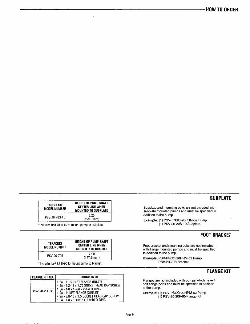
●SUBPLATEHEIGHT OF PUMP SHAFT
MODEL NUMBERCENTER LINE WHEN
MOUNTED TO SUBPLATE
I PSV-20-20S-10 I 6.25(158.8 mm) I
‘Includes bolt kit B-1 6 to mount pump to subplate.
WBPLATE
Subplate and mounting bolts are not included withsubplate mounted pumps and must be specified inaddition to the pump.
Example: (1) PSV-PNSO-20HRM-52 Pump(1) PSV-20-20S-1 O Subplate
FOOT BRACKET
PSV-20-70B
Foot bracket and mounting bolts are not includedwith flange mounted pumps and must be specifiedin addition to the pump.
Example: PSV-PSCO-20HRM-62 PumpPSV-20-70B Bracket
FLANGE KIT NO. ] CONSISTS OF
I 1 EA - 1-1/2” NPT FLANGE (INLET)I [ 4 EA - 1/2-13X 1.75 SOCKET HEAD CAP SCREW I
1 EA - 1/8X 1-7/8X 2-1/8 O-RINGPSV-20-20F-60 1 EA - 1“ NPT FLANGE (OUTLET)
4 EA - 3/8-16X 1,5 SOCKET HEAD CAP SCREW1 EA-1/8x l-15/16 xl-9/160-RING
FLANGE KIT
Flanges are not included with pumps which have 4bolt flange ports and must be specified in additionto the pump.
Example: (1) PSV-PSCO-20HRM-62 Pump(1) PSV-20-20F-60 Flange Kit
Page 14

ROBERT BOSCH FLUID POWER CORPORATIONP.O. BOX 2025RACINE, WISCONSIN 53401-2025 U.S.A.Phone (414)554-7100, Fax (414)554-7117
PRINTED IN U.S.A.
9 535 233 089HPUS AKY 003/2 US (1.96)