engineering controls plan dtsc closure · pdf filef:\projects\2013\20132993 - exide vernon...
TRANSCRIPT
f:\projects\2013\20132993 - exide vernon permitting assistance\sec files\reports\closure plan 11-2015\appendix g\appendix g 11 10 2015.docx
ENGINEERING CONTROLS PLAN
DTSC CLOSURE PLANCLOSURE IMPLEMENTATION PLAN APPENDIXATTACHMENT 14-1
AND
SCAQMD RULE 1420.1 COMPLIANCE PLAN
FOR CLOSURE ACTIVITIES
SCAQMD RULE 1420.1(p)
Prepared For:
EXIDE TECHNOLOGIES Vernon, California
Prepared By:
ADVANCED GEOSERVICES West Chester, Pennsylvania
f:\projects\2013\20132993 - exide vernon permitting assistance\sec files\reports\closure plan 11-2015\appendix g\appendix g 11 10 2015.docx
Project No. 2013-2993-21
May 15, 2015 Revised July 28, 2015
Revised November 24, 2015 Revised October 19, 2016
September 29, 2017
d:\documents (3)\exide\cip\cip-final sent to dtsc oct2017\attachment 14\appendix g-cip attm#14 - draft body rlso 2017-09-29 (003).docxf:\projects\2013\20132993 - exide vernon permitting assistance\sec files\reports\closure plan 11-2015\appendix g\appendix g 11 10 2015.docx
1-1
1.0 INTRODUCTION 1.1 PURPOSE This plan describes engineering controls to minimize release of liquids and fugitive emissions of lead and other toxic metals in air during closure of the Exide facility in Vernon, California. This document presents the general engineering control requirements for closure activities, as well as specific requirements for anticipated work activities for Phase 1 and Phase 2 closure. 1.2 SCOPE OF CLOSURE ACTIVITIES The scope of closure activities, including work tasks, locations and estimated quantities, is provided in the Closure Plan and updated and refined in the Closure Implementation Plan. The scope of closure activities is not reiterated in this plan. 1.3 RCRA FACILITY INVESTIGATION The RCRA Facility Investigation (RFI) may be implemented at the facility concurrent with closure activities. Engineering controls for the RFI are addressed in separate SCAQMD-approved mitigation plans and are not addressed in this plan. 1.4 COMPLIANCE PLAN This plan addresses SCAQMD requirements and constitutes the Compliance Plan for Closure Activities per Rule 1420.1(p)(2).
d:\documents (3)\exide\cip\cip-final sent to dtsc oct2017\attachment 14\appendix g-cip attm#14 - draft body rlso 2017-09-29 (003).docxf:\projects\2013\20132993 - exide vernon permitting assistance\sec files\reports\closure plan 11-2015\appendix g\appendix g 11 10 2015.docx
2-1
2.0 ENGINEERING CONTROLS FOR LIQUID INFILTRATION Closure activities generally include decontamination of equipment, areas and buildings with pressure washers. Engineering controls are intended to minimize infiltration of decontamination liquid into existing floors or pavement and sumps. Prior to wet decontamination, the concrete or asphalt floor surface will be vacuum cleaned to remove accumulated dirt, inspected for cracks and other damaged areas where liquids could infiltrate. Cracks will be vacuum cleaned to remove loose dust and dirt from within the cracks/damaged area. Vacuum cleaning will be performed using a SCAQMD-permitted HEPA vacuum. The cracks/damaged areas will be sealed by installing MasterSeal (Sonolastic) ® SL1™ or equivalent. Concrete sumps will also be inspected for cracks and other areas where liquids could infiltrate. Cracks will be cleaned using a SCAQMD-permitted HEPA vacuum. HETRON® 922 Corrosion/Heat Resistant Epoxy Vinyl Ester Resin, or equivalent, will be applied to the bottom and interior sidewalls of concrete sumps with cracks, damage or exposed concrete in accordance with manufacturer’s instructions. Wet decontamination of equipment within the floor and sump area will occur following completion of curing in accordance with manufacturer’s recommendations.
f:\projects\2013\20132993 - exide vernon permitting assistance\sec files\reports\closure plan 11-2015\appendix g\appendix g 11 10 2015.docx
3-1
3.0 ENGINEERING CONTROLS FOR FUGITIVE EMISSIONS IN AIR 3.1 GENERAL The goal of the engineering controls for fugitive emissions in air is to meet standard South Coast Air Quality Management District (SCAQMD) requirements pertaining to dust and emission controls to prevent emissions of lead and other toxic metals during the closure activities. The closure activities for Phase 1 and assumed activities for Phase 2 are provided in the Closure Plan and Closure Implementation Plan (CIP). Closure activities generally may include the following potentially lead-dust generating activities: Phase 1 (Closure)
Inventory removal; Unit and equipment decontamination; Unit and equipment removal; Removal of emission control equipment filters; Emission control equipment (including ducts) decontamination and deconstruction; Building decontamination; Building gutting; Concrete milling, scarification and/or hydroblasting; Building deconstruction; and, Concrete, pavement, soil and soil gas sampling.
Phase 2 (Contingent Closure) Pavement removal; Soil excavation; Soil stabilization; Backfill; Grading; Cap installation; Paving; Monitoring well maintenance; Lysimeter installation; and, Soil gas sampling probe installation.
The closure activities will be conducted in accordance with SCAQMD Rule 1420.1 (h) (Housekeeping). 3.2 DEFINITIONS High Efficiency Particulate Air (HEPA) Filter - a filter capable of trapping and retaining at least 99.97 percent of all monodispersed particles of 0.3 micrometer in diameter or larger (SCAQMD Rule 1403). SCAQMD Business Days – Tuesday through Friday, excluding holidays.
f:\projects\2013\20132993 - exide vernon permitting assistance\sec files\reports\closure plan 11-2015\appendix g\appendix g 11 10 2015.docx
3-2
3.3 WORK LOCATIONS The location of closure activities is provided in the Closure Plan. Closure activities occur in one of two types of locations: (1) within an the existing Total Enclosure Building or Temporary Enclosures, and (2) outside of an existing Total Enclosure Building or Temporary Enclosure. 3.3.1 Existing Total Enclosure Buildings The existing Total Enclosure Buildings are as follows:
Desulfurization Building (Mud Tank Building); RMPS Building; Reverb Feed Room Containment Building; Blast Feed Room Containment Building Baghouse Building; and, Smelter Building.
The following emission control equipment is currently operating at the facility and provides negative pressure for the aforementioned Total Enclosure Buildings. This emission control equipment is expected to remain in operation during closure with typical maintenance and repair until the equipment must be turned off, decontaminated and deconstructed as part of closure:
Soft Lead Baghouse; Hard Lead Baghouse; Material Handling Baghouse; East and West MAC Baghouses; MAPCO Scrubber; and, North and South Torit Baghouses.
The existing operating air handling equipment will continue to operate to maintain negative pressure while decontaminating units and equipment, dismantling equipment, decontaminating building interiors, building gutting, and removal of metal wall and roof panels (i.e., de-skinning). At this point, only structural steel (i.e., columns, trusses) and concrete walls will remain. The existing emission control equipment will not be operated while removing structural steel or concrete walls (i.e., the baghouses and associated equipment will be turned off). The operating level of the equipment will be reduced as the size of the service area decreases to achieve negative pressure that meets the minimum requirements while maintaining a safe work environment (i.e., excessive negative pressure could pull the enclosure in on itself, putting personnel within at risk). The air handling equipment at the existing Total Enclosures will maintain a negative pressure of at least 0.02 mm of Hg (0.011 inches of H2O). Measurements will be conducted using the existing monitoring system or a temporary monitoring system. The in-draft velocity will be maintained at
f:\projects\2013\20132993 - exide vernon permitting assistance\sec files\reports\closure plan 11-2015\appendix g\appendix g 11 10 2015.docx
3-3
greater than 300 feet/minute and will be determined by placing an anemometer at the center of the plane of an existing equipment or mandoor of the Total Enclosure, or any opening that is readily accessible from the work area (i.e., ground surface or scaffold). If the sequence of closure prevents existing emission control equipment from providing negative pressure for the aforementioned buildings, then existing equipment will be re-ducted to provide negative pressure, or a temporary negative air system with a SCAQMD-permitted HEPA filtration will be used. It is expected that the Torit and MAC Baghouses will provide negative pressure through building deconstruction. An area for personnel to remove soiled personal protective equipment (PPE) and decontaminate boots will be located at each main entry point in the Total the Enclosures. The closure tasks occurring within Total Enclosure Buildings with existing operating emission control equipment and the associated engineering controls are summarized on :. the attached Engineering Control Summary table.table. 3.3.2 Temporary Enclosures Closure Decontamination and deconstruction activities outside of Total Enclosure Buildings or HAKI (temporary enclosures) with existing operating emission control equipment will be conducted within temporary enclosures or the HAKI system with a negative air system with SCAQMD-permitted HEPA filtration. The size of the enclosure will be dictated by the work task and size of equipment. The temporary enclosure will be constructed of a frame covered with one layer of 9 6-mil minimum heavy fire resistant reinforced plastic sheeting. The negative air unit will be sized to provide a minimum of 4 complete air changes per hour based on the size of the enclosure. The tent will be inspected hourly to ensure that there are no tears or leaks. Work inside the temporary enclosure will be suspended if a tear or leak is found until the tear or leak is repaired. Deconstruction of concrete and masonry walls may be performed without the use of enclosures if characterization chip sampling for the interior and exterior of the wall has been performed and the results demonstrate that the concrete has total lead concentrations less than 320 mg/kg. However, effective dust control and air monitoring measures will be used throughout the course of the work regardless of total lead concentrations. A protective clothing change area will be established at the ingress/egress into the area. The change area will consist of a small tent placed immediately adjacent to the temporary enclosure. Poly sheeting will be installed between the temporary enclosure and the tent to seal off any openings and provide positive ventilation thru the change area. Personnel entering the work area will don PPE prior to entry and will remove the soiled PPE upon exit. Multiple layers of poly sheeting will be installed on the floor of the change area. The uppermost layer will be removed and bagged for disposal once personnel have removed their soiled PPE. The soiled PPE and plastic sheeting will be placed into a properly labeled container for offsite disposal.
f:\projects\2013\20132993 - exide vernon permitting assistance\sec files\reports\closure plan 11-2015\appendix g\appendix g 11 10 2015.docx
3-4
The air handling equipment at the temporary enclosures will maintain a negative pressure of at least 0.02 mm of Hg (0.011 inches of H2O). Measurements will be conducted using a temporary monitoring system. The in-draft velocity will be maintained at greater than 300 feet/minute (fpm) and will be determined by placing an anemometer at the center of the plane of an existing equipment or mandoor of the temporary enclosure, or any opening that is readily accessible from the work area (i.e., ground surface or scaffold). If access into the temporary enclosure is required, an airlock-type temporary door with at least 300 fpm draft, verified using a handheld anemometer, will be constructed to provide access into and out of the temporary enclosure. The work area will be vacuumed using a vacuum equipped with a SCAQMD-permitted HEPA filtration prior to the start of work and, at a minimum, at the end of each shift. More frequent cleaning using the SCAQMD-permitted HEPA vacuum will be performed if dust is present on the floor. Once the work is complete, the roof and interior of the temporary enclosure will be cleaned using SCAQMD-permitted HEPA-equipped vacuums to remove any dust prior to removal. The interior of the temporary enclosure will be wiped down and sprayed with an encapsulant such as Fiberlock or similar before dismantling a temporary enclosure or removing plastic sheeting. Negative pressure will be operated for 30 minutes after spraying the encapsulant to allow the encapsulant to dry. Plastic sheeting will be folded in on itself as it is removed. In the event that a temporary full enclosure is not physically feasible, work will be conducted within a partial enclosure. A partial enclosure is a structure comprised of temporary walls or partitions on at least three sides or ¾ of the perimeter and uses an existing permanent structure wall for the final wall and roof support. Enclosure performance criteria (negative pressure, draft etc.) described above will not be adjusted for partial enclosures. (a structure comprised of walls or partitions on at least three sides or ¾ of the perimeter). It is anticipated that free-standing temporary enclosures will be constructed for the Oxidation Tank Area, Former WWTP, and WWTP. Where possible, temporary enclosures will be re-used. For example, the temporary enclosure for the Former WWTP may be sized so that it can be re-used at the WWTP. The existing roof and columns at the Container Storage Areas, Drop Out System area, and West Yard Truck Wash will be used to support temporary enclosure walls. A temporary enclosure wall will separate the Central Container Storage Area (Unit 1) and the Drop Out System area. Smaller moveable temporary enclosures will be used for activities outside of these areas, such as cleaning an individual inlet structure or sump, as they will be limited in size. The closure tasks occurring within temporary enclosures are described in the attached Engineering Control Summary table.table.
f:\projects\2013\20132993 - exide vernon permitting assistance\sec files\reports\closure plan 11-2015\appendix g\appendix g 11 10 2015.docx
3-5
3.4 GENERAL ENGINEERING CONTROLS 3.4.1 General Methods Exide and its contractors will implement the following general engineering controls at all locations to minimize emissions during implementation of the Closure Plan.
At the start of closure activities in a particular work area, accumulated dust in the work area that may contain lead or other toxic metals will be removed from horizontal surfaces, such as building columns, upper rafters and supports, and from equipment using wet wash down methods and/or SCAQMD-permitted HEPA- equipped vacuums. The dust will be collected and recycled at a secondary lead smelter or disposed off-site. Any large debris generated during the work shall be placed into bags or wrapped in poly sheeting prior to removal from the work area. At the Total Enclosure Building, the roll-up doors in the vicinity of the dust collection will be closed during dust removal.
Any dust, dirt or sediment accumulations will be removed with a SCAQMD-permitted HEPA-equipped vacuum or using wet methods. Brooms will not be used for dry sweeping, but may be used for scrubbing/cleaning a surface if the broom and the surface are wet. Use of shovels will be limited to those materials which cannot successfully be removed with a SCAQMD-permitted HEPA-equipped vacuum.
During the actual work of removing the dust, dirt, sediment accumulations or waste material, the material shall be kept wetted or vacuumed to mitigate fugitive emissions produced at the work surface. All materials cleaned up from this work shall be collected and transported to a designated area inside the Total Enclosure for storage and disposal.
The liquid run off from areas that are wetted shall be contained or directed into drains and collected for treatment so as not to allow the liquid run off to evaporate and cause a secondary means of dust to be entrained into the air
All lead-contaminated equipment and materials will be stored in a manner that does not generate fugitive lead-dust, or will be cleaned by wet wash or a SCAQMD-permitted HEPA filter-equipped vacuum. Large piles of material will not be stored near the Total Enclosure roll-up doors to minimize the release of fugitive emissions through the rollup doors when open.
Equipment and vehicles shall be decontaminated inside the Total Enclosure Building prior to exiting the building.
No outside work will be performed when sustained winds exceed 12 MPH or instantaneous wind gusts exceed 20 MPH as measured by the Dust Mitigation Oversight representative with a Pocket Weather Tracker 4500NV.
No work inside the Total Enclosures will be performed if the negative air system for the work area is not operating, and it is intended to be operating.
All equipment, including SCAQMD-permitted HEPA-equipped vacuums and negative air pressure equipment, will have current SCAQMD permits to
f:\projects\2013\20132993 - exide vernon permitting assistance\sec files\reports\closure plan 11-2015\appendix g\appendix g 11 10 2015.docx
3-6
construct/operate. The permits shall be held by the Contractor or subcontractor conducting the work. Exide will not hold the permits.
The established plant speed limit of 5 mph as required by the Basic Safety Orientation Form HS002, Rev 3.19.2014 shall be required of every employee, contractor and visitor.
Exide will designate an environmental staff person whose responsibility it is to assure ongoing and sustained compliance with applicable SCAQMD Rules and Regulations. This environmental designee shall be trained and knowledgeable of Rule 1420.1 and Rule 1420 and be empowered to expeditiously employ sufficient mitigation measures and stop work to gain facility compliance.
All facility trash and debrihazardous wastes designated for offsite disposal will be placed in covered containers. prior to transfer to a rolloff container within the Total Enclosure Building.
All personnel shall ensure that all spent PPE (i.e., gloves, boots and Tyvek coveralls) are disposed in closed containers.
The preferred method for metal cutting will be cold cutting. Cutting with torches will be conducted only if necessary. When the work includes “hot” techniques like cutting torches, welders, burners, etc., Exide’s AIS’s HOT WORK PERMIT will be used.
All records will be maintained by Exide and its contractors for 5 years. In addition, copies of all records will be furnished to DTSC at the end of construction activities.
3.4.2 Total Enclosure Buildings The following activities will be performed inside the Total Enclosure Buildings. Each overhead door location at the Total Enclosure Buildings will be equipped with potable water for decontamination of materials and equipment prior to transfer outside of the enclosure building. The overhead door will remain closed during all decontamination activities for material and equipment transfer to prevent the release of contaminated overspray out of the building. Items will be decontaminated in a designated area then transferred to the staging/load out corridor and await loading onto trucks. Once loaded the trucks will be decontaminated prior to exiting the enclosure. Both decontamination and staging areas will be decontaminated once daily at a minimum after items have been removed. The decontamination area floor will be cleaned prior to removal of the piece of equipment to ensure lead residue is not transferred outside of the Total Enclosure Building. It is anticipated that the Corridor will be used as a decontamination area for materials, equipment and vehicles to the extent possible during Phase 1. Rollup doors of the Total Enclosure Buildings will be kept closed as much as possible during the closure activities. Additional detail is noted in Section 3.5. 3.4.3 Work Within Temporary Enclosures All removed debris at temporary enclosure work areas shall be placed and sealed in 55-gallon drums or a lined hopper and covered bins, or may beand taken to the Total Enclosure Building and
f:\projects\2013\20132993 - exide vernon permitting assistance\sec files\reports\closure plan 11-2015\appendix g\appendix g 11 10 2015.docx
3-7
deposited into the roll-off container. The exterior surfaces of the 55-gallon drums and hoppers bins shall be rinsed or wet cleaned prior to being taken outside of the temporary enclosure. Oversized debris not fitting within drums or hoppers shall be wrapped in plastic tarps or sheeting and sealed using adhesive tape. The plastic tarp or sheeting shall be rinsed or wet cleaned prior to removal from the temporary enclosure. 3.4.4 Drilling, Pavement Removal and Placement and Soil Activities Drilling (excluding direct push and roto-sonic techniques), pavement removal and soil handling activities will be completed in an enclosure (total enclosure or temporary enclosure) with negative air and SCAQMD-permitted HEPA filtration. Direct push (geoprobe) and roto-sonic drilling techniques do not generate cuttings and may be performed without the use of an enclosure, although the sample extraction area shall be located within an enclosure. Concrete or asphalt cutting/drilling may be performed outside Total Enclosure Buildings and will be conducted using wet methods to minimize generation of dust. The concrete being removed will be kept damp to minimize the generation of dust. Additional dust control will include applying a fine water mist directly on the work surface during the deconstruction activities. A fine water mist will also be applied to the concrete and soil as it is being excavated to minimize the generation of dust. For areas where pavement must be removed, including drilling locations, grading of soils prior to pouring concrete or asphalt paving shall only be performed if soil surface that will be disturbed has a minimum 12% moisture content. Newly imported crushed aggregate or sand used as subgrade for new paving is not required to meet the 12% moisture requirement. In accordance with SCAQMD Rule 1466, aAny soil grading/leveling project involving more than 50 cubic yards of removal with total lead concentrations over 320 mg/kg which has the potential to generate any dust shall be performed under temporary negative pressure enclosures maintained through the use of a SCAQMD-permitted HEPA negative air machines. Regardless of whether or not the grading is performed under temporary negative pressure enclosures, water or a stabilizing agent will be applied in sufficient quantities to prevent the generation of visible dust plumes when the work area is not immediately to be covered by plastic sheeting, geotextile fabric, newly imported subgrade, concrete, asphalt, or paving material. Effective dust control and air monitoring measures will be employed during all portions of the work regardless of total lead concentrations. Any drilling, pavement removal and soil disturbing activities outside of the Total Enclosure Buildings will be performed only when sustained wind velocities are less than as noted in Section 3.4.1. 3.4.5 Waste Management 3.4.5.1 Roll-off Containers All materials intended for off-site disposal or recycling will be washed as indicateddecontaminated as applicable in the Closure Implementation Plan (CIP) prior to placement in a roll-off container.
f:\projects\2013\20132993 - exide vernon permitting assistance\sec files\reports\closure plan 11-2015\appendix g\appendix g 11 10 2015.docx
3-8
Roll-offs will be staged within the Total Enclosures to minimize trips into and out of the building as well as minimize the possibility of dust being released into the environment that could be generated when placing materials into the roll-off container. The roll-off will be similar to roll-offs currently in use at the facility. The roll-off container shall have metal or hard plastic covers and will be covered when not in use (i.e., when materials are not being actively placed into it). The exterior of the roll-off container will be decontaminated with potable water and tarped prior to removal from the Total Enclosure Building. Along with the tarping, shrink wrap plastic shall be applied over the tarp that shall extend from the top of the container to below the tarp on the container sides to further reduce the chance for fugitive emissions. Roll-off Containers will be totally contained where no dust or liquid leaking is allowed during transport. Containers used for debris collection, storage and transport, including but not limited to the roll-off containers, shall be completely sealed prior to transport across open areas of the facility outside of Total Enclosures Buildings. 3.4.5.2 Truck Trailers The following procedures shall be used for loading of bulk waste material into truck trailers, including but not limited to feed material, plastic chips, sediment, residue, concrete or soil, but not to materials being recycled or reused.
Each end dump trailer will be inspected upon arrival to ensure that the vehicle is visually clean. The inspection will be noted on the pre-loading checklist (see attached Pre-Loading checklist in Attachment 2 of the Closure Implementation Plan). Trucks which are not visually clean will be turned away.
The material shall be carefully loaded with front end loaders into leak proof / end dump trailers in a manner to prevent or minimize any fugitive dust generation during the loading operation. The use of water sprays on dusty stockpile material shall be utilized to help in fugitive dust control during loading. Also, water misting sprays shall be utilized at the loading point of the end dump trailers while the material is transferred into the trailers.
Each end dump trailer shall be first inspected and examined to ensure there are no cracks or holes in the container prior to lining the containers in preparation for loading of the trailers. This inspection shall be noted on the pre-loading checklist (see attached Pre-Loading checklist).
The end dump trailers are a leak-proof design and after inspection for cracks or holes in the container shall be lined at the facility with a single 106-mil poly propylene liner prior to loading any material. This will enhance the existing gasketed rear door.
The 106-mil poly propylene liner shall be of such a dimension in length and width in order to make a “burrito” type enclosure around the loaded material using industrial type duct tape after the material has been loaded. This procedure mimics that used to transport material containing asbestos.
The rib structure, if present, on top of the end dump trailers shall be rotated out of the way prior to lining, loading and completion of the burrito wrap. The rib
f:\projects\2013\20132993 - exide vernon permitting assistance\sec files\reports\closure plan 11-2015\appendix g\appendix g 11 10 2015.docx
3-9
structure shall then be rotated back into position for cleanup and securely covering the trailer with tarp material.
The rib structure, if present, above the end dump trailer and the top edges of the trailer shall be completely wiped clean with wet clothdecontaminated after completion of loading of the material into the trailer in order to remove any dust or debris collected on the ribs structure or top edges during the loading operation.
After cleaning of the rib structure, if present, and top edges of the trailer, the outside of the trailer will be pressure washeddecontaminated to remove any dust or debris from the loading operations.
Each end dump trailer shall be securely covered with a tarp system in a manner to cover all gaps and to provide for a sealed trailer during removal and shipment.
The tarped trailer and truck shall be first inspected to ensure that there are no gaps and that the container is fully secured and sealed and then power spray washed with city water to remove exterior dust from the trailer, tarp and truck.
All of the above activities shall be conducted in the Reverb Feed Room Corridor section (with the door to the Corridor closed during loading and decontamination, and will be opened only during entry and exit) inside the Total Enclosure Building which is under negative pressure and which is vented to air pollution control system which is permitted by SCAQMD and is in full operation and is equipped with SCAQMD-permitted HEPA filtration.
The truck and trailer will be inspected for adequacy of decontamination and complete a Decon Checklist (see attached Decon checklist).
Trucks used for off-site shipments of material shall go through Unit 87, West Yard Truck Wash before leaving the facility. Oversized vehicles, that cannot fit within the truck wash station may be washed using wet methods and/or wet wipes outside the truck wash station. The trucks with the end dump trailers shall not be stored at the facility. Exide shall maintain records of washed trucks on the Truck Wash Log/Spread Sheet and records maintained inside the Bandini Street guard station, or other appropriate location at Exide, and made available to SCAQMD and DTSC staff, upon request.
The transport trucks shall be dry and not dripping water from the inside of the trailer prior to leaving the facility. There can be no uncertainty regarding existence of any leaks vs. dripping of water from the West Yard Truck wash. Dripping of liquid waste during offsite transport is not allowed.
3.4.6 Scrap Metal Management All scrap metal materials (pipe, ducting, panels) which are too large for the scrap roll-offs shall be cut down to shipping size within the remaining portions of the Total Enclosure Building or a temporary enclosure per Section 3.3.2. Sized scrap metal will be washed with potable waterdecontaminated as indicated in the Closure Implementation Plan., and placed in roll-offs using the procedures in Section 3.4.5. 3.4.7 Electrical Supply
f:\projects\2013\20132993 - exide vernon permitting assistance\sec files\reports\closure plan 11-2015\appendix g\appendix g 11 10 2015.docx
3-10
The facility’s existing electrical service will be used to the extent possible during closure. If the existing electrical service is not available during a particular work task, temporary electrical power generators with SCAQMD and/or CARB permits (if applicable) will be used. 3.4.8 Modifications Even with good planning and engineering controls implementation, elevated readings may occur at the ambient monitors. The work activities will be assessed and procedures modified as needed prior to resuming work. 3.5 SPECIFIC ENGINEERING CONTROLS The following engineering controls will be implemented for the tasks shown. Pursuant to Section 25 of the Closure Plan, alternative methods outlined in the DTSC-approved Closure Implementation Plan and including methods which consider the use of the HAKI structure (such as stack removal and deskinning) may be followed in lieu of those listed below. 3.5.1 Inventory Removal Removal of waste inventory shall be done either manually, with no tools, or with a variety of tools (such as shovels, bars, jack hammers and pumps) and utilizing mobile equipment to transport the materials. The removed materials shall be transported to the appropriate location for loading into a shipping container. The work area, including the floors adjacent to and around the specific material to be cleaned up, shall be cleaned of any dust by wet methods or vacuumed with a vacuum equipped with an SCAQMD-permitted HEPA filtration prior to the start of work. During the actual work of removing the material, the material shall be kept wetted to mitigate fugitive emissions produced at the point of impact. 3.5.2 Stack Capping The stacks associated with existing emission control equipment shall be capped and sealed prior to decontamination and deconstruction of existing emission control equipment. The capping/sealing will be completed by installing a gasketed, steel plate to the top of the stack. The plate is secured to the stack by bolted flanges to tightly seal the plate and to prevent the plate from sliding off the stack in a windy condition. Since the stack is outside and above the roof of the Total Enclosure Building, the capping will occur outside of the Total Enclosure Building. Prior to the baghouses stack removals, the top of each stack opening will be sealed and wrapped with 6-mil plastic. A window will be cut within the stack section below the roof line which will allow for placement of a 6 mil poly sheathing on the inside of the stack above the cut locations to cap the bottom of the stack section. The poly sheeting will be placed on both sides of the cut so the stack section remaining in-place is capped also. The stack will be wrapped with poly sheeting at the top and bottom only.
f:\projects\2013\20132993 - exide vernon permitting assistance\sec files\reports\closure plan 11-2015\appendix g\appendix g 11 10 2015.docx
3-11
3.5.3 Stack and Ventilation A-Pipe Removal The work will include the removal of the existing emission control equipment A-pipe, stacks and stack support structures which extend through the roof of the Total Enclosure Building. 3.5.3.1 Stack Removal The crane rigging crew will secure the crane and prepare to lift. Once secured, the stack will be cut below the roof line. As allowed by the calculations in Attachment 10, Duct Modification Plan, a small section the roof of the FEU will be opened to allow the stack to be lowered while negative pressure is maintained on the FEU. The crane will then safely lower the cut section of stack down into the FEU where it will be decontaminated within the confines of the building and within the segmented enclosure. Decontamination will not occur prior to lowering the stack into the building. This procedure modifies Closure Plan Appendix G while continuing to protect the environment. The changes result in not wrapping with a 6-mil poly sheathing due to the potential safety concern of placing workers within a crane basket for extended periods to wrap the stacks and the fact the stacks will be lowered into the FEU for decontamination rather than being lowered to the ground outside of the negative pressure enclosure precludes the need for secondary containment provided by the proposed sleeve. The stacks begin near the ground surface within the Total Enclosure Building, and extend upward through the roof and project above the roof to varying heights. A scaffold system will be installed on the roof to provide a means to construct a temporary enclosure per Section 3.3.2 around each existing stack support structure prior to their removal. The temporary enclosure will be large enough to enclose the roof opening required to remove the stack. The scaffold will be totally enclosed using reinforced fire resistant poly sheeting. The temporary enclosure will be operated under negative pressure and vented to a SCAQMD-permitted HEPA filtration control device. The roof in the area of the scaffolding will be cleaned using SCAQMD-permitted HEPA vacuums and washed prior to installation of the scaffolding. All water used for washing the roof areas shall be captured and treated properly to prevent a secondary means of fugitive emissions into the air. Once the exterior scaffold has been erected and enclosed, the structure that supports the stack will also be wrapped with fire resistant poly sheeting to provide secondary protection. The installation of the secondary enclosure will be completed by accessing the pipe support structure from inside of the building. The support structure will be removed within the temporary enclosure. Roof sheet metal and roof structural steel will be removed within the temporary enclosure as needed to allow removal of the stack. Lifting lugs will be welded to the top of the stack. A minimum 9 mil plastic sheeting tube will be placed over the stack section which projects above the temporary enclosure. The plastic sheeting tube will be under negative pressure as it will be connected to the temporary enclosure at the stack support structure. A crane will be used to hold the weight of the stack. The stack will be cut using cold methods near the roof line and within the temporary enclosure. The cut section of stack will be lifted up and the end of the stack covered. The cut section will be lifted up above the roof and lowered to the ground. The hole in the roof will be covered until the next section of stack is ready
f:\projects\2013\20132993 - exide vernon permitting assistance\sec files\reports\closure plan 11-2015\appendix g\appendix g 11 10 2015.docx
3-12
to be removed. Additional sections of stack within the building will be removed using similar methods (i.e., cut, cover the end, lifted to above roof, lowered onto the ground). It is anticipated that each stack will be removed in approximately 3 sections. The roof of the temporary enclosure will be covered after all stack sections have been removed. Structural roof steel and sheet metal will be installed over the opening in the roof. The temporary enclosure will be removed. 3.5.3.2 A-Pipe Removal Windows will be cut into the Reverb A-pipe at both ends below the FEU roof, and a 6-mil poly sheeting will be placed inside the Reverb A-pipe at both ends to cap the ends of the Reverb A-pipe. The poly sheeting will be placed to both sides of the cut so the A-pipe remaining in-place will also be capped. The Reverb A-pipe will only be wrapped at each end. Then, a crane rigging crew will secure the crane and prepare to lift the Pipe. Once secured, the Reverb A-pipe will be cut at both ends. As allowed by the calculations in Attachment 10, Duct Modification Plan, a section of the roof of the FEU will be temporarily opened along the length of the Reverb A-pipe to allow the Reverb A-pipe to be lowered within the existing Segment 2 enclosure while negative pressure is maintained on the FEU. Calculations have been performed to verify sufficient negative air will be maintained during this activity. The crane will then safely lower the Reverb A-pipe down into the FEU where it will be decontaminated within the confines of the building and within the segmented enclosure. The roof sheathing will then be resealed by placing poly sheathing used for making the HAKI roof over the void created during the removal. These spliced in sections of sheathing will be chemically welded as per their manufacturer’s recommendations. Decontamination will not occur prior to lowering the Reverb A-pipe into the building, since it was never used and because it extends above the maximum elevation of the FEU. This procedure modifies the method described in Closure Plan Appendix G Section 3.5.3.2, while continuing to protect the environment. The changes result in not wrapping with a 6-mil poly sheathing due to the potential safety concern of placing workers within a crane basket for extended periods to wrap the stacks and the fact that the stacks will be lowered into the FEU for decontamination rather than being lowered to the ground outside of the negative pressure enclosure, which precludes the need for secondary containment provided by the proposed sleeve.
The Blast A-Pipe will be enclosed by the Segment 2 FEU. It will be gross decontaminated in-place, then deconstructed using methods similar to other equipment/buildings. Final decontamination will be conducted after deconstruction.
The following tasks will be conducted to remove the A-pipe:
Wash down the exterior of the A-pipe during roof decontamination. Install scaffolding for the temporary enclosure from the ground floor up through
the roof and around the A-pipe. Install minimum 10-mil plastic on the temporary enclosure scaffold structure above
the roof.
f:\projects\2013\20132993 - exide vernon permitting assistance\sec files\reports\closure plan 11-2015\appendix g\appendix g 11 10 2015.docx
3-13
Make an opening in the Smelter Building roof for negative air pressure into the temporary enclosure.
Check for holes in the A-pipe and repair if needed with silicone, 18-gage sheet metal and self-tapping screws.
Tap on the A-pipe to knock down any buildup inside the pipe and remove all debris. Wash the interior of the A-pipe with a 360-degree high pressure water spray head
on a dolly connected to a cable at the top. Contain all water and transport to the wastewater treatment plant.
Provide a crane to assist in the removal of the A-pipe. Provide cold cutting equipment and a portable SCAQMD-permitted HEPA vacuum
for all cold cutting. Remove the A-pipe stairs and lower to the ground level within the temporary
enclosure. Remove the east side of the A-pipe and lower to the ground within the temporary
enclosure. Remove the west side of the A-pipe and lower to the ground within the temporary
enclosure. Remove the A-pipe support bridge and lower to the ground within the temporary
enclosure. Cover the openings in the building roof and walls from the removal of the A-pipe
using sheet metal, silicone sealant, and self-tapping screws. Openings will be covered for safety, maintenance of negative pressure, and roof washing.
3.5.4 Emission Control Equipment Removal Spark arrestors or equivalent precautions will be employed when hot work will be vented to dry filter media. All materials removed will be washed with potable water prior to placement into a container for proper offsite disposal or recycling. Scrap metal management procedures in Section 3.4.6 will be used. 3.5.5 Baghouse Bag Removal A temporary enclosure equipped with a SCAQMD-permitted HEPA-filter will be erected within the Total Enclosure across the top compartment doors of the baghouse and around the bottom collection hoppers of the baghouse. This enclosure is being put in place to prevent any fugitive dust from leaving the baghouse unit cells and lower hopper sections. These engineering controls shall prevent fugitives from the removal of old bags. Service platforms will be covered with plastic sheeting and extend up and over the handrails in order to contain any dust that may fall when removing the filters. Filter bags will be removed from each cell and placed into a leak tight plastic bag and sealed. These bags shall be placed in a roll-off container that is staged inside of the Total Enclosure Building. Accumulated dust will be removed from horizontal surfaces using wet wash down methods and/or SCAQMD-permitted HEPA vacuums. All collection hoppers and screw housings will be cleaned
f:\projects\2013\20132993 - exide vernon permitting assistance\sec files\reports\closure plan 11-2015\appendix g\appendix g 11 10 2015.docx
3-14
out using collection screws and SCAQMD-permitted HEPA vacuums. The plastic sheeting on the service platform will be rolled up after use and placed into a leak tight plastic or other impermeable material and then placed in a covered roll-off container. Equipment will be decontaminated by pressure washing and deconstructed. 3.5.6 Brick Removal Brick removal will be done by handheld rivet busters, spade tip hammers, etc.. During the removal process, technicians will utilize a misting system placed within the stack above all areas they are working to maintain a fog or mist of water at all times, effectively suppressing dust. All removed debris, interior buildup, brick and rinseate will be collected and properly containerized for reuse, eventual offsite disposal or on-site treatment at a Dewatering Container and the WWTP. If the equipment containing brick can be moved (i.e., blast furnace crucible), the equipment will be moved to the decontamination area at the Corridor for removal of brick. The brick will be removed using wet deconstruction techniques, which will include pre-wetting the refractory brick and applying a fine water mist onto the surface being demolished. The brick will be transferred into a roll-off container or suitable shipping vehicle staged within the Total Enclosure Building. Once the brick has been removed, the remaining equipment will be cleaned by washing with potable water. If the equipment containing brick cannot be moved, the brick will be pre-wetted at its current location and a fine water mist will be applied to the surface being demolished. The brick will be transferred into a roll-off container or suitable shipping vehicle staged within the Total Enclosure Building. 3.5.7 Crack Sealing Floor cracks will be cleaned and sealed prior to area or building decontamination as noted in Section 2.0. Cracks will be cleaned using a SCAQMD-permitted HEPA-vacuum and will have caulk applied. When sealing floor cracks in the Total Enclosure Building, the roll-up door in closest proximity to the work area shall remain fully closed during the activity to prevent any cross draft and for a period of one hour after completion of the repairs. Due to concerns with water infiltration into unsealed cracks, the floor surfaces will not be wetted down prior to the work. 3.5.8 Sump Sealing Sumps will be cleaned and sealed prior to area or building decontamination as noted in Section 2.0. Depending on the sump condition, work may include wet cutting and jack hammering of coating and surface concrete, abrasive preparation of concrete surface, and application of chemical resistant coating. Work will be conducted in the Total Enclosure Building or in a temporary enclosure. All removed debris shall be placed and sealed in 55-gallon drums or a lined hopper and taken to the Total Enclosure Building and deposited into the roll-off container. The 55-gallon drums or hoppers shall be rinsed or wet cleaned prior to being taken outside of the temporary enclosure.
f:\projects\2013\20132993 - exide vernon permitting assistance\sec files\reports\closure plan 11-2015\appendix g\appendix g 11 10 2015.docx
3-15
3.5.9 Decontamination Engineering controls during decontamination of area and building walls, ceilings and floors will be provided by the negative pressure equipment associated with the Total Enclosure Building or temporary enclosure. 3.5.10 Deconstruction The exact sequence of deconstruction of the RMPS Building, Reverb Feed Room, Baghouse Building and Smelter Building will be established during closure based on the Deconstruction Engineering Survey. The Blast Furnace Feed Room will likely be deconstructed first. The Baghouse Building will likely be deconstructed before the RMPS Building, Reverb Feed Room and Smelter Building as it is structurally dependent on the RMPS Building, Reverb Feed Room and Smelter Building. Existing operating emission control equipment associated with these areas (Soft Lead, Hard Lead, Material Handling, MACs, MAPCO Scrubber, Torits) will continue to operate until they are shut down, decontaminated and deconstructed in conjunction with the building deconstruction sequence. The Torits and the MACs will likely be used to maintain negative pressure during deconstruction. The Closure Plan, as originally written, called for the construction of portable Negative Air Enclosures for roof and vertical wall panel decontamination and removal. This proposed method created a considerable amount of work being performed under “high risk” conditions for the Project, including AIS Technicians working on elevated roof structures with unknown stability, while being tied off and in appropriate fall protection at all times. AIS had concerns that placing workers and a negative air enclosure on the roof, as described in the Closure Plan increased the health and safety risk for the workers and the Project. To mitigate this concern, AIS identified a full enclosure system (HAKI system) and its design was submitted to the DTSC and SCAQMD on December 9, 2016. The USEPA has determined that the Facility is “no longer an affected source” under NESHAP because Exide cannot physically operate as a secondary lead smelter having permanently disabled the Blast and Reverberatory furnaces, which means that NESHAP requirements are not be part of the final Title V Permit.
The SCAQMD has issued a renewed Title V Permit to govern closure activities, including Exide’s use of the HAKI system. Exide’s closure activities will comply with the final Title V Permit.
As described in Exide’s HAKI submittal (see Attachment 8, FEU – HAKI Truss System), which was conditionally approved by the DTSC on December 27, 2016 date, AIS will utilize a segmented full enclosure unit (FEU), which will be composed of a combination of conventional scaffolding for the walls and HAKI Truss System for the roof. The system is a truss system capable of spanning the entire width of the structure and will provide secondary enclosure by utilizing a track system within the trusses to place poly sheathing. See Attachment 8 for additional detail for the FEU and the HAKI system. The thickness of the plastic used for the full enclosure will include (1) roof structure of 20-mil fire retardant plastic, and (2) wall structure of 14- mil fire retardant plastic. With a wind load rating of 75mph, this will withstand all anticipated wind gusts. AIS has performed work utilizing the above mentioned system on multiple projects throughout Southern
f:\projects\2013\20132993 - exide vernon permitting assistance\sec files\reports\closure plan 11-2015\appendix g\appendix g 11 10 2015.docx
3-16
California. Negative air machines and/or additional ducting from the existing baghouses will be added as necessary to maintain constant negative air pressure to continuously prevent a fugitive dust event. Duct modifications are provided in Attachment 10, Duct Modification Plan. The durability of the secondary containment will allow crews to safely dismantle or abate buildings enveloped by this system in most weather conditions and help prevent the possibility of work stoppage due to rain or dust emission. In addition, the enclosure structure will provide access points along the perimeter of the structure to all wall panels and provide extra tie off locations which will decrease any cumbersome stretches of lanyards and allow safer and easier access for building decontamination.
As shown in Attachment 8 FEU – HAKI Truss System, a HAKI system FEU will be constructed at Segment 1 (West buildings). At this time the HAKI system will also be installed at the Corridor. Following work within Segment 1, a HAKI system FEU will be constructed at Segment 2 (East buildings). Following work within Segment 2, a HAKI system FEU will be constructed at Segment 3 (Center buildings). The Oxidation Tank Area and electrical systems north of the Baghouse Building will be removed prior to construction of Segment 3 using a portable enclosure unit.
To allow for the deconstruction of walls the FEU scaffolding walls will extend up and penetrate through the existing roof in the baghouse building. The roof penetration will be conducted within a temporary enclosure. The plastic sheeting on the scaffolding walls will be sealed to the adjacent roof outside the FEU. Any guy wire penetrations through the existing roof will occur after the FEU is operational, and will not require a temporary enclosure. The HAKI system will be anchored to the existing floor as shown in Attachment 8, FEU – HAKI Truss System.
As discussed in Attachment 10, Duct Modification Plan, the negative air pressure for the FEU will be monitored using existing and temporary monitoring devices. The proposed temporary monitoring device will meet SCAQMD requirements. Detail on the device will be provided separately.
In the event that there is a minor breach in the FEU during the Project the following contingency plan for minor repairs will be implemented:
Maintain supply of repair materials onsite including: Poly Sheathing for walls, HAKI Roof Sheathing, Chemical Welding Supplies an specialty tools
Have designated trained repair person onsite daily that is familiar with HAKI and FEU systems
Complete inspection of temporary enclosure to identify defects;
An additional plastic sheeting layer on areas of enclosure(s) requiring repair
Increased negative pressure for Total Enclosure Building and or temporary enclosure
f:\projects\2013\20132993 - exide vernon permitting assistance\sec files\reports\closure plan 11-2015\appendix g\appendix g 11 10 2015.docx
3-17
Additional temporary enclosure cleaning with SCAQMD-permitted HEPA vacuum
Add water misting devices at work locations
Decrease threshold wind speed for outdoor work stoppage
Add wind speed threshold for work stoppage at temporary enclosures, including Total Enclosure Building in the process of deconstruction
The enclosure system utilizes conventional scaffolding for walls and a HAKI Truss System for the roof portion. This system is a truss system capable of spanning the entire width of each of the Segment’s structures and will provide a secondary enclosure by utilizing a track system within the trusses to place poly sheathing.
Negative pressure will be maintained on the building while de-skinning (i.e., removing wall and roof panels) using existing emission control equipment or temporary equipment. A windbreak will be constructed on outside walls by putting heavy duty 10 mil minimum plastic sheeting on scaffolding or supported by structural building elements. The wall skin will be removed panel by panel using the following methods:
Spray panel to be removed with water to control dust expected at panel overlaps. Cut the fasteners and maintain panel in its original position. Vacuum dust accumulations within panel overlaps with SCAQMD-permitted
HEPA vacuum. Wipe the overlaps and face of structural members with a damp rag or pressure wash
the overlap to remove dust accumulations. Remove the panel and lower to the ground in a controlled fashion.
Following wall skin removal, the roof skin will be removed panel by panel using the following methods:
Within an approximately 10 ft by 10 ft by 10 ft mobile negative pressure tent on top of the roof, remove 50% of the roof panel screws while vacuuming with a SCAQMD-permitted HEPA vacuum. Seal holes with silicone as the screws are removed.
Cover roof panels with 10 mil minimum plastic sheeting and seal to the perimeter scaffolding and structures. Use rope or sand bags to hold the plastic sheeting in place as needed. This procedure will completely enclose the section of the roof to be removed with plastic sheeting.
f:\projects\2013\20132993 - exide vernon permitting assistance\sec files\reports\closure plan 11-2015\appendix g\appendix g 11 10 2015.docx
3-18
Use standoff supports with rounded ends to separate the plastic sheeting from roof panels without damaging the plastic sheeting. The standoff supports will be approximately 4 to 6 inches tall.
Remove roof panels in small sections by cold cutting from inside the building while ensuring the 10-mil minimum plastic sheeting is not damaged. Remove the cut section and lower to the ground in a controlled fashion. It is anticipated that the roof panels will be removed in a row along the peak of the roof, parallel to the girt line, and then downwards row by row towards the roof/wall interface.
As roof panels are removed, remove remaining screws connecting the roof panel to the structural steel from above or below the roof.
As panels are removed, allow plastic sheeting to lay on structural steel. Use rope or cables between structural girts and trusses to create a grid to support the plastic sheeting.
Panels will be sorted by material type, and containerized for off-site recycling or disposal. The wall windbreak and roof plastic will be removed. Once the work is complete, the scaffolding and plastic will be cleaned using SCAQMD-permitted HEPA-equipped vacuums to remove any dust prior to removal. The interior of the windbreak will be wiped down and sprayed with an encapsulant such as Fiberlock or similar before dismantling the windbreak or removing plastic sheeting. Negative pressure equipment will be shut down. Structural steel for the walls and roof will be removed to the top of concrete wall using cold cutting and conventional equipment. The buildings will be systematically dismantled from the roof level down to the ground level. It is anticipated that gross deconstruction will be performed using large-tracked excavators (operating weight greater than 50,000 lbs) equipped with rotating shear or grapple attachments to cut and remove structural members down to the concrete slab/foundation level. Concrete walls will be sampled on both sides to determine the lead content of the concrete. If the total lead concentration is above 320 mg/kg, then deconstruction must be performed within an enclosure operated under negative pressure. If total lead concentration is below 320 mg/kg, then enclosure and negative pressure are not required, but dust control and air monitoring measures will be used throughout the course of the work regardless of total lead concentrations. Concrete wall deconstruction to surrounding grade shall be performed using hydraulic hammers or concrete shears attached to standard construction equipment. Hydraulic hammers and shears shall be operated with continuous water spray/misting techniques to prevent generation of concrete dust. High pressure water deconstruction techniques may be performed in limited areas in lieu of hydraulic hammers and concrete shears with water spray/misting techniques. High pressure water deconstruction can include the use of a “water knife” to cut concrete apart or high pressure nozzles to pulverize the concrete. By its very nature, deconstruction with high pressure water prevents the generation of dust, but requires the collection and management of large amount of water. This method also provides the ability to remove concrete surfaces to very discrete depths and horizontal limits.
f:\projects\2013\20132993 - exide vernon permitting assistance\sec files\reports\closure plan 11-2015\appendix g\appendix g 11 10 2015.docx
3-19
3.5.12 Drilling Soil sampling, soil gas sampling, lysimeter installation and soil gas probe installation will occur using drilling. Drilling techniques are expected to include direct push technology (i.e. Geoprobe), Rotosonic and/or hollow stem auger, and the specific technique for each location will be selected based on several factors, including: depth of required sampling, type of samples required, and contaminants of concern. Geoprobe and Rotosonic drilling have little to no potential for generation of dust because both techniques allow advancement of the boring without the creation of cuttings and collect a continuous sample in a plastic sleeve. Hollow stem auger drilling causes greater potential for fugitives, and its use will be minimized. 3.5.12.1 Drilling Inside Total Enclosure Building Prior to the start of drilling activities within the Total Enclosure Building, the floor surfaces where the soil sampling is to take place shall be wetted down or power washed depending on how clean the concrete surface is. Water misting and wet dust suppression shall be done through the entirety of the project including but not limited to all concrete cutting, and jack hammering. The rollup door in proximity to the work area shall be closed at all times during sampling. Concrete sections from the drilling not retained for laboratory analysis shall be placed into a roll-off container that is staged inside of the Total Enclosure Building. Roll-off management shall be as discussed in Section 3.4.5. To identify subsurface utilities, the sample location will be spray-painted or otherwise marked. At least 48 hours prior to drilling, Underground Service Alert (USA) will be called to identify subsurface utilities in public areas. A combination of previous utility locations, facility knowledge, or hand augering the upper most 5 feet and/or private utility location will be used to identify subsurface utilities in privately owned areas. 3.5.12.2 Drill Site Preparation Outside Total Enclosure The mitigation measures in this section are designed for drilling outside of the Total Enclosure Building. Drill site preparation will involve identifying subsurface utilities; coring or sawing through pavement materials; verifying the absence of subsurface utilities at the boring locations; setting up work zones; providing the containers required to contain waste materials; laying down polyethylene sheeting or equivalent to minimize the post-drilling cleanup operation; and setting up a sample examination area. To identify subsurface utilities, the sample location will be spray-painted or otherwise marked. At least 48 hours prior to drilling, Underground Service Alert (USA) will be called to identify subsurface utilities in public areas. A combination of previous utility locations, facility knowledge, or hand augering the upper most 5 feet and/or private utility location will be used to identify subsurface utilities in privately owned areas.
f:\projects\2013\20132993 - exide vernon permitting assistance\sec files\reports\closure plan 11-2015\appendix g\appendix g 11 10 2015.docx
3-20
If the drill site is paved with concrete or asphalt, it willmay be cored or saw-cut to provide access to the underlying soil. The dimensions of the opening in the pavement will be large enough to accommodate the drill rig’s auger/stem and/or lysimeter surface finishing, whichever is appropriate for the location. Coring or saw-cutting will be conducted as noted in Section 3.4.1.
If required, hHand augering to clear the boring location for utilities will take place within the temporary enclosure equipped with SCAQMD-permitted HEPA filtration device for lead and operated under negative pressure. The clearance diameter should be at least as wide as the largest diameter hole that will be mechanically drilled. Location-specific conditions may require deeper clearance. The ground surface will first be covered with plastic sheeting, at least 10 mil or greater, extending to at least six feet beyond the boring location. The temporary enclosure will then be set into place over the boring location. No hand auger work will take place unless inside an enclosure with a SCAQMD-permitted HEPA filtration device for lead which is operating under negative pressure. The hand auger will be removed from the hole taking care to retain the subsurface material in the auger and a disposable aluminum pan placed under it. The subsurface material will be examined and logged, and any required samples collected for analysis. The excess material and the disposable pan will be placed in a sealed 55-gallon drum or lined hopper which is completely covered or tarped, except during loading. The drum or hopper is taken into the Total Enclosure where it is dumped into the roll-off. The roll-off or drum is washed with potable water and shrink wrapped before being taken outside the Total Enclosure Building as noted in Section 3.4.5.1. After the boring location is cleared for utilities, the plastic sheeting will be vacuumed with a vacuum equipped with a SCAQMD-permitted HEPA filter for lead. The work support zone will be delineated in the field using a combination of orange traffic cones, barricades, and yellow caution tape as necessary. The dimensions of the zone will be established in the field based on site-specific geography. At a minimum, the work zone will be large enough to accommodate the drill rig, any required support vehicles, waste containers, and a sample processing area. The sample processing area may be located at a location near the work zone if adequate space is not present at the drilling location. The area around the boring site, underneath the drill rig, connected support truck, sample processing area, and the waste containers will be protected by laying down heavy-gauge (10 mil or greater) polyethylene sheeting. The edges of the plastic sheeting will be secured to prevent unintended uplift from wind. A second layer of sheeting will be placed over the primary layer and will generally extend at least 6 feet from the boring location. Second layers of sheeting will not be used in walking areas due to slippery conditions. A wind screen will be set up on the upwind side of the proposed boring between 5 and 10 feet from the boring location. At the end of each working day, the plastic sheeting will be vacuumed with a vacuum equipped with a SCAQMD-permitted HEPA filter for lead. On completion of drilling operations, the polyethylene sheeting will be rolled up and disposed of along with other miscellaneous solid wastes in sealed drums or lined hopper, and the borings will be grouted. 3.5.12.3 Direct-Push Drilling
f:\projects\2013\20132993 - exide vernon permitting assistance\sec files\reports\closure plan 11-2015\appendix g\appendix g 11 10 2015.docx
3-21
Shallow soil borings, including soil gas probes, proposed to be drilled to depths up to 72 ft bgs (below ground surface) are expected to be completed by direct push drilling methods with a truck-mounted rig. Direct push refers to tools and sensors that are “pushed” into the ground without the use of drilling to remove soil or to make a path for the tool. A Geoprobe® direct-push rig relies on a relatively small amount of static (vehicle) weight combined with percussion as the energy for advancement. Direct push drilling is one of the faster methods of drilling and sampling shallow borings and does not generate soil cuttings. The Geoprobe® system uses hollow, steel push rods ranging from 1-inch to 3.25-inches in diameter and are typically four feet in length. As the push rod is advanced into the ground, additional lengths of rod are added. Various sampling tools can be attached to the rods to allow for continuous or depth-discrete soil sampling. 3.5.12.4 Rotosonic Drilling Rotosonic drilling is typically used for monitoring well installation. Monitoring well installation is not anticipated during the closure activities; however, the procedures have been provided in the event they are needed. Rotosonic drilling utilizes high-frequency resonant energy to advance an outer, temporary conductor casing(s) and an internal core barrel into the underlying formation(s). Hydraulic motors on the drill head oscillate internal unbalanced weights. As a result of the weights being unbalanced, extreme vibrations are created in the drill stem allowing the drill to penetrate virtually any material with minimal side wall disturbance. In addition to the vibration, rotosonic drilling uses both rotation and down pressure of the drill casing to advance the borehole. The core barrel provides a continuous core of subsurface materials, while the conductor casing stabilizes the boring and provides a temporary seal of water-bearing unit(s) during coring. Rotosonic drilling also allows for telescoping of multiple outer conductor casings to seal-off multiple water-bearing units as needed. MATERIALS AND EQUIPMENT: The following materials and equipment are required for implementation:
1. Rotosonic drill rig and associated equipment and materials; 2. Plastic Sheeting (10-mil min.); 3. Duct tape; 4. Flat shovel; 5. Hose and spray nozzle; 6. Hand auger; 7. Covered containment vessel for soil cuttings (drums, hopper or roll-off bin); 8. Plastic sleeves (socks) for core samples; 9. Portable safety/windscreen (4-ft high and 10-ft long min); 10. Four-sided temporary enclosure constructed of fire resistant poly sheeting fitted
over a PVC frame and equipped with a SCAQMD-permitted HEPA filtration device for lead and operated under negative pressure while work is being performed; and,
11.9. Absorbent booms or pads.
f:\projects\2013\20132993 - exide vernon permitting assistance\sec files\reports\closure plan 11-2015\appendix g\appendix g 11 10 2015.docx
3-22
The following procedures are based upon ASTM D6914-04 (2010) “Standard Practice for Sonic Drilling for Site Characterization and the Installation of Subsurface Monitoring Devices.” Preliminary Set up
1. Spread double layer of 10-mil reinforced plastic sheeting over work area with proposed boring no closer than 6-ft from any edge. Secure edges using duct tape or sand bags to prevent unintended uplift from wind or equipment. Spread a single layer of plastic sheeting of 10-mil in any area of foot traffic including the path to and beneath the enclosure for examination of soil samples if one is being used and secure edges with duct tape or sand bags. Spread double layer of 10-mil reinforced plastic sheeting over work area with proposed boring no closer than 6-ft from any edge. The second layer of plastic is not used in walking areas due to slippery conditions. Secure edges using duct tape or sand bags to prevent unintended uplift from wind or equipment. Spread a single layer of 10-mil plastic sheeting in any area of foot traffic including the path to and beneath the enclosure for examination of soil samples if one is being used and secure edges with duct tape, unless the soil examination area is a significant distance away and facility traffic crosses the path. In this situation, the samples will be double-lined with two layers of plastic socks.
2.1. 3. Erect safety/wind screen on upwind side of proposed boring between 5 and 10 feet
from location of boring. Distance may be greater than 10 feet if lead driller believes proximity will create a safety hazard for proposed drilling operations. (Note plastic sheeting is not expected to extend to safety/wind screen, although efforts shall be made to limit foot traffic beyond plastic sheeting).
4.2. Connect hose with nozzle to water source and activate water source and confirm
sprayer is operational.
5.3. Examination of soil samples outside of the Total Enclosure Building will be done within the temporary enclosure equipped with SCAQMD-permitted HEPA air filtration device for lead and operated under negative pressure while soil examination is taking place.
6.4. Utility Clearance, as required will be conducted as noted in Section 3.5.12.1.
7.5. If excess soil comes in contact with the exterior ground surface, it shall be immediately removed by means of a vacuum equipped with a SCAQMD-permitted HEPA filter for lead. I n the event that a large amount of soil comes in contact with the ground surface, it shall be removed using a flat shovel or similar tool that will minimize damage to the plastic sheeting and then vacuumed using a SCAQMD-permitted HEPA filter for lead. Constant and direct water spray shall be applied as the soil is removed and placed in the appropriate waste containment vessel. If excess water begins to pond, the driller shall reduce the amount of water being applied and deploy absorbent booms or pads to control runoff.
f:\projects\2013\20132993 - exide vernon permitting assistance\sec files\reports\closure plan 11-2015\appendix g\appendix g 11 10 2015.docx
3-23
Drilling
1. Once the borehole has been adequately cleared, the outer temporary conductor casing (drill casing) and inner core barrel are alternately advanced. The outer drill casing, constructed of flush-threaded carbon steel in 5 and 10-foot lengths, will be used as a temporary conductor casing and remain in the ground to prevent borehole collapse and to prevent cross communication between water-bearing units as the inner core barrel is advanced and then retracted for the collection of lithologic samples. The length of individual retrieved lithologic cores may vary between a few feet and ten feet, depending upon recovery percentages.
2. The diameter of the outer drill casing and core barrel will be determined by location-specific goals and the need for temporarily sealing of shallow water-bearing units, but the planned 4-inch diameter wells will be set in nominally 8-inch diameter casings. The inner core barrel diameter is generally one to two inches smaller than the outer drill casing.
3. Once the inner core barrel is retracted, a clear plastic sock shall be placed over the core barrel and slight resonance shall be applied to reduce the friction between the core sample and the inside wall of the core barrel. The sample will then slowly extrude from the core barrel into the plastic sock for examination by the field geologist. The top of the plastic sock will be tied tightly to prevent the release of any of the subsurface material prior to being carried to the sample examination enclosure. Once the inner core barrel is retracted, two layers of clear plastic sock shall be placed over the core barrel and slight resonance shall be applied to reduce the friction between the core sample and the inside wall of the core barrel. The sample will then slowly extrude from the core barrel into the plastic sock for examination by the field geologist. The top of the plastic sock will be tied tightly to prevent the release of any of the subsurface material prior to being carried to the sample examination enclosure.
4. A temporary, above ground containment area filled with water shall be maintained surrounding the borehole, such that any excess spoils that may fall into the containment area would be submerged. When cleaning slough from the boring, soil shall be wetted, or placed directly in 10-mil plastic liners, and transferred to a suitable waste containment vessel. Soil temporarily placed in hoppers shall be routinely wetted and covered with 10-mil plastic sheeting.
5. When the borehole is advanced through artificial fill soil and penetrates
approximately 5 feet into native sediments, and all spoils have been containerized, the top layer of plastic sheeting covering the borehole area shall be removed and placed in the waste containment vessel. Removal shall be performed by gently folding the plastic over on itself to contain any residual soil and to prevent dust dispersion. The underlying layer of plastic sheeting shall remain in-place until completion of drilling.
f:\projects\2013\20132993 - exide vernon permitting assistance\sec files\reports\closure plan 11-2015\appendix g\appendix g 11 10 2015.docx
3-24
6. In general, experienced field geologists can visually examine and manually manipulate soil materials within the plastic sock such that the soil can be adequately described and classified. When closer examination of soil cores is deemed necessary by the field geologist, or if the core sample must be subsampled, it shall first be carried into the temporary enclosure before being cut open. Any slough present in the soil cores will be logged accordingly.
7. When relatively undisturbed soil samples are required, a California-modified, split spoon sampler may be used. Such samplers are advanced using a standard automatic hammer. Soil samplers shall only be opened within the temporary enclosure.
8. Upon completion of the drilling and management of soil cuttings, the work zone shall be cleaned up. The remaining layer of plastic sheeting shall be removed using techniques described above for the top layer. The resulting ground surface shall be vacuumed using a SCAQMD-permitted HEPA filter-equipped vacuum for lead and then inspected by on-site field representatives to ensure that materials associated with the drilling have been removed. If residual materials are still present, the area shall be vacuumed again and then washed down with water. Wash water shall be flushed into the on-site storm water management system or removed using a SCAQMD-permitted HEPA filter-equipped vacuum for lead.
9. Sealed 55-gallon drums containing soils will be placed in either the Central Container Storage Area (Unit 1) or placed into a roll-off located within the Total Enclosure Building as directed by Exide. For drums placed in the Central Container Storage Area, they will be washed with potable water and staged until there are a sufficient number to be placed on a trailer or truck and taken to a landfill for proper disposal. For soils placed into a roll-off, the procedures in Section 3.4.5.1 will be used.
10. Drums containing plastic sheeting, absorbent booms and non-soil debris generated by the drilling operations may be taken to the Total Enclosure Buildings and placed into the tarped roll-off designated for such materials. The procedures in Section 3.4.5.1 will be used.
11. No work will be performed if sustained wind speeds exceed the speeds noted in Section 3.4.1.
Preparation for Well Construction
1. When the targeted aquitard is encountered, the outer casing will be advanced into the aquitard and soil cuttings will be removed from the casing using the core barrel.
2. The outer casing will then be retracted approximately one foot and the borehole gauged to ensure that it had remained open.
f:\projects\2013\20132993 - exide vernon permitting assistance\sec files\reports\closure plan 11-2015\appendix g\appendix g 11 10 2015.docx
3-25
3. Upon confirmation of an open borehole, medium bentonite chips will be emplaced, extending from the bottom of the borehole to at least five feet up into the outer casing.
4. The outer casing will then be retracted an additional foot to allow the chips to completely fill the boring annulus.
5. Finally, the outer casing will be keyed into the aquitard by advancing the casing through the bentonite seal and at least one foot into the undisturbed aquitard materials.
6. To verify the efficacy of the seal, standing groundwater will be bailed from the conductor casing and a Solinst™ water level meter will be used to record the rate of water level recovery. If the rate of recovery is less than 6 inches in two hours, the seal will be considered effective and drilling will be allowed to resume with a smaller diameter casing.
7. Upon reaching final depth, the well will be constructed following the Monitoring Well Installation and Field Sieve SOP’s that are part of the approved RFI Work Plan. Typical proposed well construction diagrams are attached for reference.
3.5.12.5 Well Construction Shallow Rotosonic drilling techniques with temporary conductor casing shall be used to drill and install the shallow monitoring wells. A continuous core of soil (ASTM D 1586) shall be collected to document lithologic conditions. The well screen (typically 10 to 20 feet maximum saturated length) shall be set at the uppermost water-bearing zone (approximately 75 to 80 feet below ground surface (BGS)). The well screen length will also be based on the thickness of the aquifer of interest. The on-site geologist shall determine the final depth of the monitoring well by trying to finish drilling on top of a silty or clay unit. To help ensure successful screening in the perched water bearing zone, the Geologist shall review boring logs from adjacent wells. Pilot boring at the location of proposed wells shall be completed prior to installation of the wells. The pilot borings shall be continuously sampled, the results compared against the previous boring logs and particular attention paid to the gradation and moisture beginning at 60 feet BGS. At the sign of first water, drilling will be advanced under the direction of the Geologist stopping periodically as deemed necessary by the Geologist to observed the accumulation of water in the boring. The bottom of the boring will be called by the Geologist when, based on professional judgment, a saturated zone capable of producing sufficient water for groundwater sampling using low flow techniques is encountered. The pilot boring shall penetrate at least 2 feet into the confining layer. Soil samples from the water bearing zone will be submitted for expedited gradation analysis and utilized to select the sand pack and screen materials.
f:\projects\2013\20132993 - exide vernon permitting assistance\sec files\reports\closure plan 11-2015\appendix g\appendix g 11 10 2015.docx
3-26
Temporary conductor casings shall remain in the hole while awaiting results of the gradation analysis unless it is more feasible to grout the hole in and drill a collocated boring to construct the well at a later time. The wells shall be constructed with 4-inch diameter schedule 40 polyvinyl chloride (PVC) with factory slotted screens and riser casing. Wells installed during the Phase 3 RFI (MW-16 and MW-17) were both constructed using 20 feet of No. 0.010-in slot PVC screen and 2/16 sand. The well screens will be sand packed to approximately two feet above the top of the screen with No. 1 sand. A minimum two-foot thick bentonite seal will be installed on top of the sand pack. The remaining annulus of each borehole will be tremie-grouted to the surface using a 95 percent cement/5 percent bentonite grout. Each shallow monitoring well will be completed with a minimum six-inch ID steel protective casing with a locking cap. The protective casing will extend from a depth of three to five feet BGS to approximately 2.5 feet above ground. A small drain hole in the protective casing will be located just above the surface seal. A neat cement or concrete seal will be placed around the protective casing to a depth of three to five feet BGS. A three-foot square well pad will be installed so that the surface slopes away from the well. Bumper guards consisting of cement or concrete-filled steel casing may be placed around the monitoring wells if the possibility of damage by vehicles exists. Wells completed in traffic and parking areas, or in visually obtrusive areas will be equipped with water-tight, 1-inch raised covers that will be set in a concrete pad as described above. Deep Rotosonic drilling techniques shall be used to drill and install the deep monitoring wells. A continuous core of soil (ASTM D 1586) shall be collected to document lithologic conditions. Deep wells will be temporarily cased into low permeability soil layers beneath the completion depth of the shallow wells. The boring will be initially advanced using 10-inch diameter temporary conductor casing to a minimum of 20 feet through the low permeability soil layer beneath the shallow wells. Once this targeted depth is reached, the shallow water bearing zone will be temporarily sealed. Drilling into the underlying aquifer will be completed with 9-inch diameter temporary conductor casing. Drilling will be advanced under the direction of the Geologist stopping periodically as deemed necessary by the Geologist to observed the accumulation of water in the boring. The bottom of the boring will be called by the Geologist when, based on professional judgment, a saturated zone capable of producing sufficient water for groundwater sampling using low flow techniques is encountered. The wells shall be constructed with 4-inch diameter schedule 40 polyvinyl chloride (PVC) with factory slotted screens and riser casing. The sand pack and slot size of the well screen will be based on the results of field sieve analysis obtained from the pilot boring. However, based on recently constructed wells at the site, it is anticipated that the wells will be constructed using 2/16 sand with 0.010-in slotted screen. The well screens will be sand packed to approximately two feet above the top of the screen, with at least 1 foot of No. 1 sand as a transition sand pack. A minimum two-foot thick bentonite seal will be installed on top of the sand pack. The remaining annulus of each borehole will be tremie-grouted to the surface using a 95 percent cement/5 percent bentonite grout.
f:\projects\2013\20132993 - exide vernon permitting assistance\sec files\reports\closure plan 11-2015\appendix g\appendix g 11 10 2015.docx
3-27
Each deep monitoring well will be completed with a minimum six-inch ID steel protective casing with a locking cap. The protective casing will extend from a depth of three to five feet bgs to approximately 2.5 feet above ground. A small drain hole in the protective casing will be located just above the surface seal. A neat cement or concrete seal will be placed around the protective casing to a depth of three to five feet bgs. A three-foot square well pad will be installed so that the surface slopes away from the well. Bumper guards consisting of cement or concrete-filled steel casing may be placed around the monitoring wells if the possibility of damage by vehicles exists. Wells completed in traffic areas, parking areas or in visually obtrusive areas will be equipped with water-tight, 1-inch raised covers that will be set in a concrete pad as described above. The wells shall be completed and protected by traffic-rated well boxes (installed slightly above the ground surface to encourage surface drainage away from the well) or steel well protector (for “stick-up” wells).
f:\projects\2013\20132993 - exide vernon permitting assistance\sec files\reports\closure plan 11-2015\appendix g\appendix g 11 10 2015.docx
3-28
3.5.12.6 Well Development Upon completion, but not sooner than 48 hours following completion of well construction, each well shall be developed to remove fine-grained material from the well casing, sand pack, and the adjacent formation. Development shall consist of the following steps:
1. Record static water level and total well depth.
2. Insert pump to mid-point of screened interval and begin pumping, or begin bailing, while recording turbidity and depth to water, until turbidity levels have stabilized. The pumping rate shall be selected so that the average entrance velocities exceed those anticipated during investigation and sampling activities (ideally 0.5 to 3.0 gpm). Water level measurements recorded at intervals during pumping shall be used to estimate the specific capacity and sustainable extraction rates of the wells for constant discharge aquifer testing, if such tests are judged necessary.
3. Discontinue pumping and perform surging. The wells shall be surged using tight-fitting, vented surge blocks to agitate the sand pack and draw fines from the sand pack and surrounding formation into the well casing. Do not use backwashing, surging, jetting or air lifting for well development. Do not add water to speed up the well development unless an approval is first obtained from DTSC.
4. Re-measure total well depth and repeat pumping and surging until turbidity levels at start of pumping are typically <5 nephelometric turbidity units (NTU).
5. The pH, electrical conductivity (EC), temperature, dissolved oxygen, turbidity, and oxygen reducing potential (ORP) of the extracted ground water shall be monitored periodically during well development. Well development data shall be recorded on well development log forms.
6. Complete a boring log and well construction log for the completed well providing date and time of construction, approximate location, well designation, materials of construction and dimensions (including diameter, total depth, etc.) and completion configuration.
3.5.12.7 Well Surveying Each monitoring well will be surveyed for location and elevation. Well locations will be surveyed to the nearest 0.5 feet relative to the California State Plane Coordinate System. Wellhead elevations will be surveyed to the nearest 0.01 foot at a marked reference point on each well casing. The newly installed monitoring well will be surveyed within 30 days of the installation using conventional techniques utilizing the control points as reference points. If the impoundment is free of liquid at the time of the monitoring well survey, the location of each sump will also be surveyed and tied into the California State Plane Coordinate System. The surveying activities will be conducted under the direct supervision of a State of California licensed Professional Surveyor.
f:\projects\2013\20132993 - exide vernon permitting assistance\sec files\reports\closure plan 11-2015\appendix g\appendix g 11 10 2015.docx
3-29
The location of all benchmarks used in the survey, as well as the date(s) of the survey, will be documented in annual monitoring reports. All wells should be re-surveyed as needed (e.g., re-surfacing, well head is modified or repaired, abnormal data, etc.). 3.5.12.8 Supplemental Dust Mitigation Measures All backfill materials (sand, bentonite, and cement) may be contaminated with lead and hexavalent chromium. The mixing of cement with water will generate dust. This mixing activity shall be subject to mixing in the temporary enclosure equipped with SCAQMD-permitted HEPA filtration for lead and operated under negative pressure. 3.5.12.9 Boring Abandonment Direct-push soil borings completed to 20 feet bgs or less will be abandoned using granular bentonite. Bentonite will be placed by hand into the boring from grade and hydrated in place with potable water. Borings that are drilled beyond 20 feet bgs will be abandoned using neat cement grout by the tremie method. A 0.5- to 1-inch diameter tremie pipe will be placed in the borehole, filled with cement grout, and removed in 5- to 10-foot sections to allow the cement to fill the vacated space at the base of the boring. This procedure will be repeated until the boring is backfilled to grade. The following day, the borings will be topped off should the cement within the borings settle overnight. 3.5.13 Well Maintenance Prior to maintenance, the area around the well will be cleaned with a SCAQMD-permitted HEPA-vacuum. The well lid will be removed and the vault area cleaned with a SCAQMD-permitted HEPA-vacuum. Required maintenance will be conducted. If concrete removal is necessary, work will be conducted in a temporary enclosure per Section 3.4.4. Debris will be collected into a sealed plastic container/bag and disposed off-site. 3.5.14 Welding Welding is not anticipated to occur during closure; however, the procedures are provided in the event they are needed. The areas to be welded will be cleaned by wiping with clean disposable wipes wet with a D-Lead Solution®. A wipe test will then be performed on the area to be welded using a Lead Wipe Test Kit (ESCA Tech Inc. Lead Test Kit). The test solution will be applied to the test kit supplied wipe. A wipe sample will be performed on 4 separate locations on each area to be welded using a new wipe wetted with the test solution. A yellow color indicates lead is present and additional cleaning is required. No color change indicates no lead is present. All 4 test locations must have a negative result prior to proceeding with the welding using standard welding techniques. The MSDS for the specific welding rod to be utilized will be reviewed. A welding rod will be utilized that does not contain lead. This process will be completed for each of the 4 areas that require additional welding. The welding will be completed immediately following the wipe testing.

f:\projects\2013\20132993 - exide vernon permitting assistance\sec files\reports\closure plan 11-2015\appendix g\appendix g 11 10 2015.docx
3-30
3.6 AIR MONITORING 3.6.1 Perimeter Ambient Air Monitoring Perimeter ambient air monitoring will be conducted by Exide as indicated in the Air Monitoring Plan (Closure Plan Appendix H) and as required per SCAQMD Rule 1420.1(p)(1). If during closure the ambient air concentrations of lead or arsenic exceed the limits in paragraphs (d)(1) and (d)(5) of SCAQMD Rule 1420.1, Exide will temporarily suspend closure-related activities that contributed to the exceedance until contingency measures in Section 5.2 are implemented. Exide shall submit a written report assessing the root cause of the exceedance and, if closure-related activities are determined to have contributed to the exceedance, Exide shall temporarily suspend the closure-related activities that contributed to the exceedance and provide a mitigation plan designed to avoid additional exceedances. The closure-related activities that contributed to the exceedance shall not re-commence until the Executive Officer, in consultation with DTSC, approves the mitigation plan and the mitigation measures are implemented. Any exceedances of ambient air concentrations specified in paragraphs (d)(1) or (d)(5) of SCAQMD Rule 1420.1 will be reported with a notification made to the 1-800-CUT-SMOG within 24 hours of receipt of the completed sample analysis. A written report will be submitted to SCAQMD’s Executive Officer no later than three business days after the notification. The written report will include the causes of the exceedance and the specific corrective action implemented. If an ambient air concentration of lead greater than 0.100 micrograms per cubic meter0.300 (g/m3) occurs for any 24-hour30-day average sample, Exide will shall report the following information in writing to the SCAQMD Executive Officer within 72 hours of when the facility knew or should have known the result, including:
Date(s) of the occurrence; Name of the monitor; 30-day average ambient lead concentrations at the monitor; Ambient lead concentration at the monitor for all associated 24-hour samples in the
30-day rangethe 24-hour sample; Potential cause or causes of the occurrence; and, Potential remedies to prevent the reoccurrence.
Similarly, if an ambient air concentration of arsenic greater than 10 nanograms per cubic meter (ng/m3) occurs for any 24-hour sample, Exide shall report the following information in writing to the SCAQMD Executive Officer within 72 hours of when the facility knew or should have known the result, including:
Date(s) of the occurrence; Name of the monitor; Ambient arsenic concentration at the monitor for the 24-hour sample;
f:\projects\2013\20132993 - exide vernon permitting assistance\sec files\reports\closure plan 11-2015\appendix g\appendix g 11 10 2015.docx
3-31
Potential cause or causes of the occurrence; and, Potential remedies to prevent the reoccurrence.
3.6.2 Real-Time Work Area Particulate Matter Monitoring Real-time work area air monitoring will be conducted as indicated in the Air Monitoring Plan (Closure Plan Appendix H) by the Dust Mitigation Oversight representative. As observing personnel note an increase in concentration of 50 g/m3 of PM10, using DustTrak devices, above background averaged over a minute and measured every 15 minutes at a location near the activity that is being conducted in conjunction with visual observation and experience, they shall direct work stoppage and then direct adjustments in the work practices and/or the applied control measures as appropriate. In response to adverse visual observations or DustTrak results, Exide and its contractors shall implement the following increased dust suppression activities. These increased dust suppression abatement activities will include, but are not limited to the following:
Stop all work outside of any Total Enclosure Building that has the potential to generate lead or other toxic metals containing dust. Negative air filtration units installed on enclosures will remain in operation for the duration of the stop work order. Equipment that was being used inside of the Total Enclosure Building shall remain in place during the stop work period.
Immediately begin application of water on all paved areas. Stop all onsite vehicle traffic outside of all Total Enclosure Buildings. All overhead doors on any Total Enclosure Building are to remain closed. Determine if there are any activities within any Total Enclosure Building that could
be contributing to the increase in dust concentration. If so, these activities will be stopped.
Determine if there are any offsite activities that are being conducted by others that are contributing to the increase in dust concentration. If so, suspend all activities outside of Total Enclosure Buildings that have the potential to generate lead and other toxic metals containing dust until additional dust mitigation has been implemented or the activity completed and the areas both on-site and off-site are cleaned.
The abatement activities described above will remain in effect until Exide and the Dust Mitigation Oversight representative determine the cause of the adverse readings and additional dust mitigation for the activity that caused the increase in dust concentration has been implemented. If the cause of the adverse Dust Trak readings cannot be attributed to any one activity outside of Total Enclosure Buildingss and no activity within any Total Enclosure Building, the work outside of the Total Enclosure Building will be restarted on a rolling basis with the activity that would be
f:\projects\2013\20132993 - exide vernon permitting assistance\sec files\reports\closure plan 11-2015\appendix g\appendix g 11 10 2015.docx
3-32
expected to generate the least amount of lead containing dust starting first. No work may resume until DustTrak readings show that the adverse dust condition does not exist anymore. The real time data from the DustTraks will be continuously monitored during this rolling start to determine if there is an increase in the dust concentrations following the restart of any one activity. If an increase is noted after restarting any activity, that activity will be stopped until additional dust suppression measures have been implemented. The rolling start activities following the activity that caused the increase in dust consideration may be restarted using the basis described above with continuous monitoring of the real time particulate data to insure none of the follow on activities causes an increase in the total particulate concentration. If after work resumes, DustTrak readings show adverse dust conditions, the dust suppression and abatement activity described above shall be implemented.
f:\projects\2013\20132993 - exide vernon permitting assistance\sec files\reports\closure plan 11-2015\appendix g\appendix g 11 10 2015.docx
3-33
3.7 1420.1 HOUSEKEEPING Exide will continue to implement those housekeeping measures outlined in SCAQMD Rule 1420.1(h) including sweeping of on-site paved areas, will be conducted as noted in the Closure Plan.
f:\projects\2013\20132993 - exide vernon permitting assistance\sec files\reports\closure plan 11-2015\appendix g\appendix g 11 10 2015.docx
4-1
4.0 OVERSIGHT Exide will retain a third partythird-party consultant to oversee implementation of the engineering controls for liquid infiltration. The name and qualifications of the third party consultant will be provided to DTSC and SCAQMD 10 business days in advance of retaining the consultant. The third party consultant(s) will provide weekly reports to Exide, DTSC and SCAQMD regarding the engineering controls, Closure activities and progress on Friday Monday of each week. The Dust Migitation Oversight representative discussed in Section 1.3.6.3 of the Closure Plan will oversee implementation of engineering controls for fugitive emissions in air and will perform real-time air monitoring. The Dust Mitigation Oversight representative will provide weekly reports to Exide, DTSC and SCAQMD regarding the engineering controls, Closure activities and progress on Friday Monday of each week. The third partythird-party consultant performing oversight of engineering controls for liquid infiltration may be the same as the consultant providing dust mitigation oversight.

f:\projects\2013\20132993 - exide vernon permitting assistance\sec files\reports\closure plan 11-2015\appendix g\appendix g 11 10 2015.docx
4-2
f:\projects\2013\20132993 - exide vernon permitting assistance\sec files\reports\closure plan 11-2015\appendix g\appendix g 11 10 2015.docx
5-1
5.0 PLAN VARIATIONS AND CONTINGENCY MEASURES 5.1 VARIATIONS FROM PLAN Though appropriate efforts have been made to anticipate closure-related activities and engineering controls, unanticipated conditions may arise from time to time that may need to be addressed. The appropriate general engineering control requirements presented within the Engineering Controls Plan will be implemented for any such activities with notification to DTSC and SCAQMD field representatives. If additional engineering controls not already listed in the Closure Plan or Closure Implementation Plan are necessary for unanticipated activities or varying conditions, then, unless an emergency requires a faster response, the additional activities will be submitted to DTSC and SCAQMD for review and approval two (2) SCAQMD business days in advance of the work. Variations from the Engineering Controls Plan must be approved by DTSC and SCAQMD. Operations associated with the variance from the plan will stop until DTSC and SCAQMD have approved the variation, unless ceasing operation while awaiting approval creates a worse environmental situation. Pursuant to Section 25 of the Closure Plan, alternative methods outlined in the DTSC-approved Closure Implementation Plan may be followed in lieu of those listed in this document. 5.2 CONTINGENCY MEASURES If ambient air concentrations of lead or arsenic exceed the limits in Rule 1420.1 (d)(1) and (d)(5), Exide will temporarily suspend closure-related activities that contributed to the exceedance until appropriate contingency measure(s) are implemented. The contingency measure or measures implemented will be specific to the closure activities occurring at the time of the exceedance. Contingency measures, listed below as required under SCAQMD Rule 1420.1(p)(2)(B), may include:
Extra water sprays on paved areas;
Extra sweeping;
Additional inspection of temporary enclosure to identify defects;
An additional plastic sheeting layer on temporary enclosure(s);
Increased negative pressure for Total Enclosure Building and/or temporary enclosure;
Additional temporary enclosure cleaning with SCAQMD-permitted HEPA vacuum;
Add water misting devices at work locations;
Decrease threshold wind speed for outdoor work stoppage; or,
Add wind speed threshold for work stoppage at temporary enclosures, including Total Enclosure Building in the process of deconstruction.

f:\projects\2013\20132993 - exide vernon permitting assistance\sec files\reports\closure plan 11-2015\appendix g\appendix g 11 10 2015.docx
5-2
f:\projects\2013\20132993 - exide vernon permitting assistance\sec files\reports\closure plan 11-2015\appendix g\appendix g 11 10 2015.docx
5-3
5.3 CONTINGENCY PLAN REVISION
If a previously unidentified activity which the contingency measures in Section 5.2 do not address contributes to the exceedances, then a revised Engineering Controls Plan will be submitted to DTSC and SCAQMD for approval before resuming closure related activities.
f:\projects\2013\20132993 - exide vernon permitting assistance\sec files\reports\closure plan 11-2015\appendix g\appendix g 11 10 2015.docx
6-1
6.0 SCHEDULE A schedule for closure phases including inventory removal, decontamination, confirmation soil sampling, removal of equipment, building decontamination, soil and soil gas sampling, and building deconstruction and their associated engineering controls is provided in Appendix F of the Closure Plan and as an attachment to this planin the Closure Implementation Plan Attachment 3 and described in Section 3.2.1. As discussed in Section 1.4.2 of the Closure Plan, progress meetings will be held at the facility weekly with Exide, the Contractor, and the Resident Engineer when field activities are occurring. DTSC, SCAQMD and the City of Vernon will be invited to attend. The meeting agenda is provided in Section 1.4.2 of the Closure Plan, and includes discussion of work activities completed during the previous week, and work activities planned for the upcoming two weeks. The meeting will satisfy the requirement of Rule 1420.1(p)(2)(C) to periodically update the schedule to reflect the progression of closure activities.
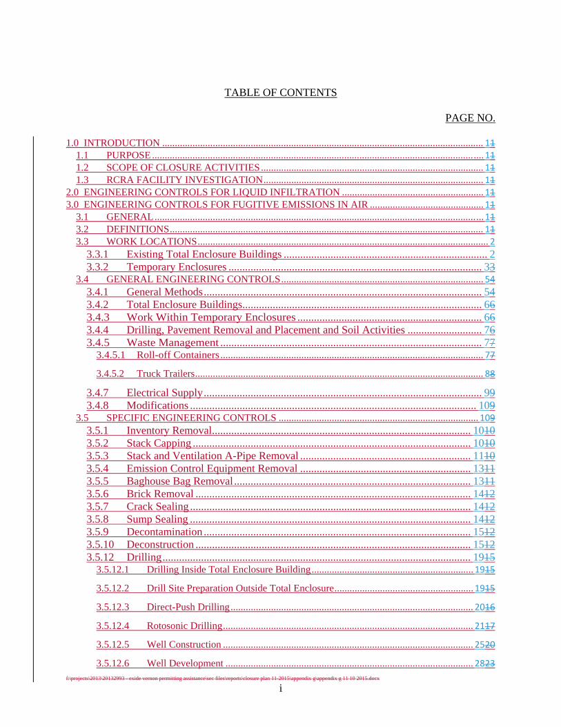
f:\projects\2013\20132993 - exide vernon permitting assistance\sec files\reports\closure plan 11-2015\appendix g\appendix g 11 10 2015.docx
i
TABLE OF CONTENTS
PAGE NO.
1.0 INTRODUCTION ............................................................................................................................... 11 1.1 PURPOSE ................................................................................................................................... 11 1.2 SCOPE OF CLOSURE ACTIVITIES ........................................................................................ 11 1.3 RCRA FACILITY INVESTIGATION ....................................................................................... 11
2.0 ENGINEERING CONTROLS FOR LIQUID INFILTRATION ........................................................ 11 3.0 ENGINEERING CONTROLS FOR FUGITIVE EMISSIONS IN AIR ............................................. 11
3.1 GENERAL .................................................................................................................................. 11 3.2 DEFINITIONS ............................................................................................................................ 11 3.3 WORK LOCATIONS ................................................................................................................... 2
3.3.1 Existing Total Enclosure Buildings .......................................................................... 2 3.3.2 Temporary Enclosures ............................................................................................ 33
3.4 GENERAL ENGINEERING CONTROLS ................................................................................ 54 3.4.1 General Methods ..................................................................................................... 54 3.4.2 Total Enclosure Buildings ....................................................................................... 66 3.4.3 Work Within Temporary Enclosures ................................................................... 66 3.4.4 Drilling, Pavement Removal and Placement and Soil Activities ........................... 76 3.4.5 Waste Management ............................................................................................... 77
3.4.5.1 Roll-off Containers ........................................................................................................ 77
3.4.5.2 Truck Trailers .................................................................................................................. 88
3.4.7 Electrical Supply ..................................................................................................... 99 3.4.8 Modifications ........................................................................................................ 109
3.5 SPECIFIC ENGINEERING CONTROLS ............................................................................... 109 3.5.1 Inventory Removal.............................................................................................. 1010 3.5.2 Stack Capping ..................................................................................................... 1010 3.5.3 Stack and Ventilation A-Pipe Removal .............................................................. 1110 3.5.4 Emission Control Equipment Removal .............................................................. 1311 3.5.5 Baghouse Bag Removal ...................................................................................... 1311 3.5.6 Brick Removal .................................................................................................... 1412 3.5.7 Crack Sealing ...................................................................................................... 1412 3.5.8 Sump Sealing ...................................................................................................... 1412 3.5.9 Decontamination ................................................................................................. 1512 3.5.10 Deconstruction .................................................................................................... 1512 3.5.12 Drilling ................................................................................................................ 1915
3.5.12.1 Drilling Inside Total Enclosure Building ................................................................ 1915
3.5.12.2 Drill Site Preparation Outside Total Enclosure ....................................................... 1915
3.5.12.3 Direct-Push Drilling ................................................................................................ 2016
3.5.12.4 Rotosonic Drilling ................................................................................................... 2117
3.5.12.5 Well Construction ................................................................................................... 2520
3.5.12.6 Well Development .................................................................................................. 2823
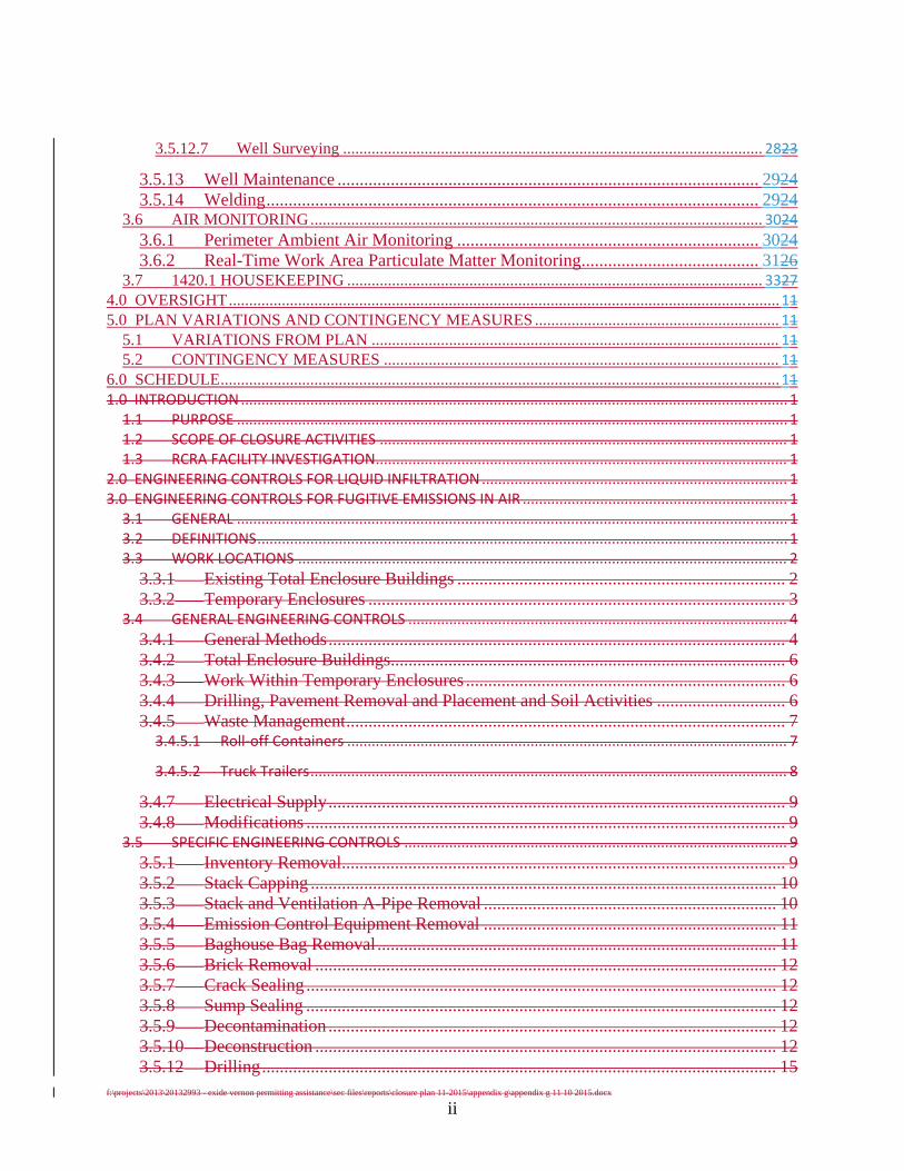
f:\projects\2013\20132993 - exide vernon permitting assistance\sec files\reports\closure plan 11-2015\appendix g\appendix g 11 10 2015.docx
ii
3.5.12.7 Well Surveying ....................................................................................................... 2823
3.5.13 Well Maintenance ............................................................................................... 2924 3.5.14 Welding ............................................................................................................... 2924
3.6 AIR MONITORING ............................................................................................................... 3024
3.6.1 Perimeter Ambient Air Monitoring .................................................................... 3024 3.6.2 Real-Time Work Area Particulate Matter Monitoring ........................................ 3126
3.7 1420.1 HOUSEKEEPING ...................................................................................................... 3327 4.0 OVERSIGHT ....................................................................................................................................... 11 5.0 PLAN VARIATIONS AND CONTINGENCY MEASURES ............................................................ 11
5.1 VARIATIONS FROM PLAN .................................................................................................... 11 5.2 CONTINGENCY MEASURES ................................................................................................. 11
6.0 SCHEDULE ......................................................................................................................................... 11 1.0 INTRODUCTION ...................................................................................................................................... 1 1.1 PURPOSE ....................................................................................................................................... 1 1.2 SCOPE OF CLOSURE ACTIVITIES .................................................................................................... 1 1.3 RCRA FACILITY INVESTIGATION ..................................................................................................... 1
2.0 ENGINEERING CONTROLS FOR LIQUID INFILTRATION ........................................................................... 1 3.0 ENGINEERING CONTROLS FOR FUGITIVE EMISSIONS IN AIR ................................................................. 1 3.1 GENERAL ....................................................................................................................................... 1 3.2 DEFINITIONS .................................................................................................................................. 1 3.3 WORK LOCATIONS ........................................................................................................................ 2
3.3.1 Existing Total Enclosure Buildings .......................................................................... 2 3.3.2 Temporary Enclosures .............................................................................................. 3
3.4 GENERAL ENGINEERING CONTROLS ............................................................................................. 4
3.4.1 General Methods ....................................................................................................... 4 3.4.2 Total Enclosure Buildings ......................................................................................... 6 3.4.3 Work Within Temporary Enclosures ........................................................................ 6 3.4.4 Drilling, Pavement Removal and Placement and Soil Activities ............................. 6 3.4.5 Waste Management ................................................................................................... 7 3.4.5.1 Roll‐off Containers ............................................................................................................ 7
3.4.5.2 Truck Trailers ..................................................................................................................... 8
3.4.7 Electrical Supply ....................................................................................................... 9 3.4.8 Modifications ............................................................................................................ 9
3.5 SPECIFIC ENGINEERING CONTROLS .............................................................................................. 9
3.5.1 Inventory Removal.................................................................................................... 9 3.5.2 Stack Capping ......................................................................................................... 10 3.5.3 Stack and Ventilation A-Pipe Removal .................................................................. 10 3.5.4 Emission Control Equipment Removal .................................................................. 11 3.5.5 Baghouse Bag Removal .......................................................................................... 11 3.5.6 Brick Removal ........................................................................................................ 12 3.5.7 Crack Sealing .......................................................................................................... 12 3.5.8 Sump Sealing .......................................................................................................... 12 3.5.9 Decontamination ..................................................................................................... 12 3.5.10 Deconstruction ........................................................................................................ 12 3.5.12 Drilling .................................................................................................................... 15
f:\projects\2013\20132993 - exide vernon permitting assistance\sec files\reports\closure plan 11-2015\appendix g\appendix g 11 10 2015.docx
iii
3.5.12.1 Drilling Inside Total Enclosure Building ....................................................................... 15
3.5.12.2 Drill Site Preparation Outside Total Enclosure ............................................................ 15
3.5.12.3 Direct‐Push Drilling ..................................................................................................... 16
3.5.12.4 Rotosonic Drilling ........................................................................................................ 17
3.5.12.5 Well Construction ....................................................................................................... 20
3.5.12.6 Well Development ...................................................................................................... 23
3.5.12.7 Well Surveying ............................................................................................................ 23
3.5.13 Well Maintenance ................................................................................................... 24 3.5.14 Welding ................................................................................................................... 24
3.6 AIR MONITORING ........................................................................................................................ 24
3.6.1 Perimeter Ambient Air Monitoring ........................................................................ 24 3.6.2 Real-Time Work Area Particulate Matter Monitoring ............................................ 26
3.7 1420.1 HOUSEKEEPING ............................................................................................................... 27 4.0 OVERSIGHT ............................................................................................................................................. 1 5.0 PLAN VARIATIONS AND CONTINGENCY MEASURES .............................................................................. 1 5.1 VARIATIONS FROM PLAN .............................................................................................................. 1 5.2 CONTINGENCY MEASURES ............................................................................................................ 1
6.0 SCHEDULE ............................................................................................................................................... 1
f:\projects\2013\20132993 - exide vernon permitting assistance\sec files\reports\closure plan 11-2015\appendix g\appendix g 11 10 2015.docx
ENGINEERING CONTROLS SUMMARY TABLE
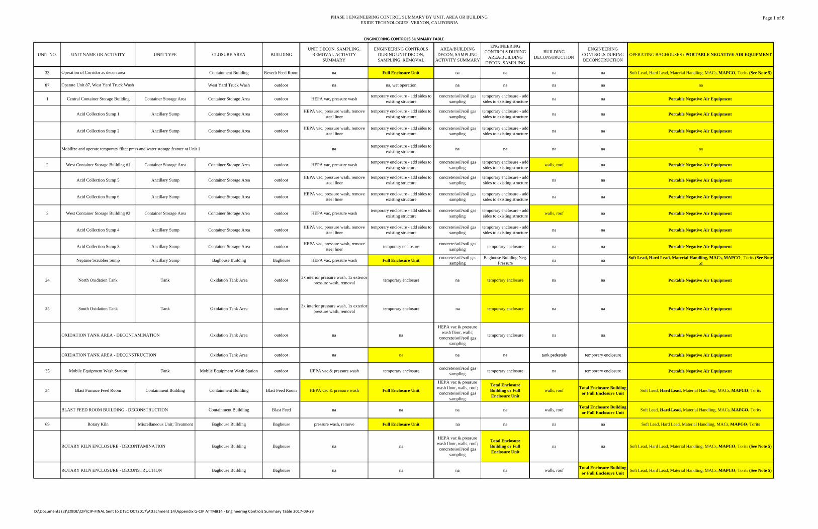
PHASE 1 ENGINEERING CONTROL SUMMARY BY UNIT, AREA OR BUILDINGEXIDE TECHNOLOGIES, VERNON, CALIFORNIA
Page 1 of 8
UNIT NO. UNIT NAME OR ACTIVITY UNIT TYPE CLOSURE AREA BUILDINGUNIT DECON, SAMPLING,
REMOVAL ACTIVITY SUMMARY
ENGINEERING CONTROLS DURING UNIT DECON, SAMPLING, REMOVAL
AREA/BUILDING DECON, SAMPLING
ACTIVITY SUMMARY
ENGINEERING CONTROLS DURING
AREA/BUILDING DECON, SAMPLING
BUILDING DECONSTRUCTION
ENGINEERING CONTROLS DURING DECONSTRUCTION
OPERATING BAGHOUSES / PORTABLE NEGATIVE AIR EQUIPMENT
33 Containment Building Reverb Feed Room na Full Enclosure Unit na na na na Soft Lead, Hard Lead, Material Handling, MACs, MAPCO, Torits (See Note 5)
87 West Yard Truck Wash outdoor na na, wet operation na na na na na
1 Central Container Storage Building Container Storage Area Container Storage Area outdoor HEPA vac, pressure washtemporary enclosure - add sides to
existing structureconcrete/soil/soil gas
samplingtemporary enclosure - add sides to existing structure
na na Portable Negative Air Equipment
Acid Collection Sump 1 Ancillary Sump Container Storage Area outdoorHEPA vac, pressure wash, remove
steel linertemporary enclosure - add sides to
existing structureconcrete/soil/soil gas
samplingtemporary enclosure - add sides to existing structure
na na Portable Negative Air Equipment
Acid Collection Sump 2 Ancillary Sump Container Storage Area outdoorHEPA vac, pressure wash, remove
steel linertemporary enclosure - add sides to
existing structureconcrete/soil/soil gas
samplingtemporary enclosure - add sides to existing structure
na na Portable Negative Air Equipment
Mobilize and operate temporary filter press and water storage feature at Unit 1 natemporary enclosure - add sides to
existing structurena na na na na
2 West Container Storage Building #1 Container Storage Area Container Storage Area outdoor HEPA vac, pressure washtemporary enclosure - add sides to
existing structureconcrete/soil/soil gas
samplingtemporary enclosure - add sides to existing structure
walls, roof na Portable Negative Air Equipment
Acid Collection Sump 5 Ancillary Sump Container Storage Area outdoorHEPA vac, pressure wash, remove
steel linertemporary enclosure - add sides to
existing structureconcrete/soil/soil gas
samplingtemporary enclosure - add sides to existing structure
na na Portable Negative Air Equipment
Acid Collection Sump 6 Ancillary Sump Container Storage Area outdoorHEPA vac, pressure wash, remove
steel linertemporary enclosure - add sides to
existing structureconcrete/soil/soil gas
samplingtemporary enclosure - add sides to existing structure
na na Portable Negative Air Equipment
3 West Container Storage Building #2 Container Storage Area Container Storage Area outdoor HEPA vac, pressure washtemporary enclosure - add sides to
existing structureconcrete/soil/soil gas
samplingtemporary enclosure - add sides to existing structure
walls, roof na Portable Negative Air Equipment
Acid Collection Sump 4 Ancillary Sump Container Storage Area outdoorHEPA vac, pressure wash, remove
steel linertemporary enclosure - add sides to
existing structureconcrete/soil/soil gas
samplingtemporary enclosure - add sides to existing structure
na na Portable Negative Air Equipment
Acid Collection Sump 3 Ancillary Sump Container Storage Area outdoorHEPA vac, pressure wash, remove
steel linertemporary enclosure
concrete/soil/soil gas sampling
temporary enclosure na na Portable Negative Air Equipment
Neptune Scrubber Sump Ancillary Sump Baghouse Building Baghouse HEPA vac, pressure wash Full Enclosure Unitconcrete/soil/soil gas
samplingBaghouse Building Neg.
Pressurena na
Soft Lead, Hard Lead, Material Handling, MACs, MAPCO , Torits (See Note 5)
24 North Oxidation Tank Tank Oxidation Tank Area outdoor3x interior pressure wash, 1x exterior
pressure wash, removaltemporary enclosure na temporary enclosure na na Portable Negative Air Equipment
25 South Oxidation Tank Tank Oxidation Tank Area outdoor3x interior pressure wash, 1x exterior
pressure wash, removaltemporary enclosure na temporary enclosure na na Portable Negative Air Equipment
OXIDATION TANK AREA - DECONTAMINATION Oxidation Tank Area outdoor na na
HEPA vac & pressure wash floor, walls;
concrete/soil/soil gas sampling
temporary enclosure na na Portable Negative Air Equipment
OXIDATION TANK AREA - DECONSTRUCTION Oxidation Tank Area outdoor na na na na tank pedestals temporary enclosure Portable Negative Air Equipment
35 Mobile Equipment Wash Station Tank Mobile Equipment Wash Station outdoor HEPA vac & pressure wash temporary enclosureconcrete/soil/soil gas
samplingtemporary enclosure na temporary enclosure Portable Negative Air Equipment
34 Blast Furnace Feed Room Containment Building Containment Building Blast Feed Room HEPA vac & pressure wash Full Enclosure Unit
HEPA vac & pressure wash floor, walls, roof; concrete/soil/soil gas
sampling
Total Enclosure Building or Full Enclosure Unit
walls, roofTotal Enclosure Building
or Full Enclosure UnitSoft Lead, Hard Lead, Material Handling, MACs, MAPCO, Torits
BLAST FEED ROOM BUILDING - DECONSTRUCTION Containment Buildling Blast Feed na na na na walls, roofTotal Enclosure Building
or Full Enclosure UnitSoft Lead, Hard Lead, Material Handling, MACs, MAPCO, Torits
69 Rotary Kiln Miscellaneous Unit; Treatment Baghouse Building Baghouse pressure wash, remove Full Enclosure Unit na na na na Soft Lead, Hard Lead, Material Handling, MACs, MAPCO, Torits
ROTARY KILN ENCLOSURE - DECONTAMINATION Baghouse Building Baghouse na na
HEPA vac & pressure wash floor, walls, roof; concrete/soil/soil gas
sampling
Total Enclosure Building or Full Enclosure Unit
na na Soft Lead, Hard Lead, Material Handling, MACs, MAPCO, Torits (See Note 5)
ROTARY KILN ENCLOSURE - DECONSTRUCTION Baghouse Building Baghouse na na na na walls, roofTotal Enclosure Building
or Full Enclosure UnitSoft Lead, Hard Lead, Material Handling, MACs, MAPCO, Torits (See Note 5)
ENGINEERING CONTROLS SUMMARY TABLE
Operation of Corridor as decon area
Operate Unit 87, West Yard Truck Wash
D:\Documents (3)\EXIDE\CIP\CIP‐FINAL Sent to DTSC OCT2017\Attachment 14\Appendix G‐CIP ATTM#14 ‐ Engineering Controls Summary Table 2017‐09‐29
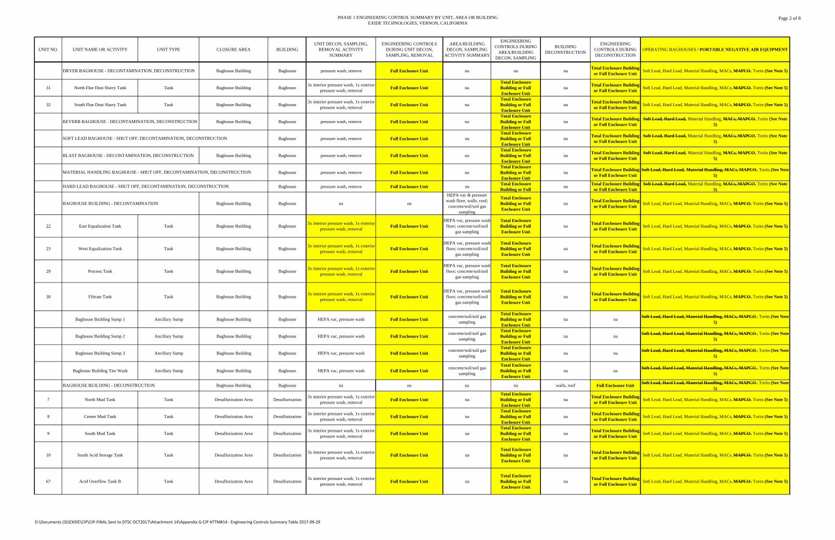
PHASE 1 ENGINEERING CONTROL SUMMARY BY UNIT, AREA OR BUILDINGEXIDE TECHNOLOGIES, VERNON, CALIFORNIA
Page 2 of 8
UNIT NO. UNIT NAME OR ACTIVITY UNIT TYPE CLOSURE AREA BUILDINGUNIT DECON, SAMPLING,
REMOVAL ACTIVITY SUMMARY
ENGINEERING CONTROLS DURING UNIT DECON, SAMPLING, REMOVAL
AREA/BUILDING DECON, SAMPLING
ACTIVITY SUMMARY
ENGINEERING CONTROLS DURING
AREA/BUILDING DECON, SAMPLING
BUILDING DECONSTRUCTION
ENGINEERING CONTROLS DURING DECONSTRUCTION
OPERATING BAGHOUSES / PORTABLE NEGATIVE AIR EQUIPMENT
DRYER BAGHOUSE - DECONTAMINATION, DECONSTRUCTION Baghouse Building Baghouse pressure wash, remove Full Enclosure Unit na na naTotal Enclosure Building
or Full Enclosure UnitSoft Lead, Hard Lead, Material Handling, MACs, MAPCO, Torits (See Note 5)
31 North Flue Dust Slurry Tank Tank Baghouse Building Baghouse3x interior pressure wash, 1x exterior
pressure wash, removalFull Enclosure Unit na
Total Enclosure Building or Full Enclosure Unit
naTotal Enclosure Building
or Full Enclosure UnitSoft Lead, Hard Lead, Material Handling, MACs, MAPCO, Torits (See Note 5)
32 South Flue Dust Slurry Tank Tank Baghouse Building Baghouse3x interior pressure wash, 1x exterior
pressure wash, removalFull Enclosure Unit na
Total Enclosure Building or Full Enclosure Unit
naTotal Enclosure Building
or Full Enclosure UnitSoft Lead, Hard Lead, Material Handling, MACs, MAPCO, Torits (See Note 5)
REVERB BAGHOUSE - DECONTAMINATION, DECONSTRUCTION Baghouse Building Baghouse pressure wash, remove Full Enclosure Unit naTotal Enclosure Building or Full Enclosure Unit
naTotal Enclosure Building
or Full Enclosure UnitSoft Lead, Hard Lead, Material Handling, MACs, MAPCO, Torits (See Note
5)
Baghouse pressure wash, remove Full Enclosure Unit naTotal Enclosure Building or Full Enclosure Unit
naTotal Enclosure Building
or Full Enclosure UnitSoft Lead, Hard Lead, Material Handling, MACs, MAPCO, Torits (See Note
5)
BLAST BAGHOUSE - DECONTAMINATION, DECONSTRUCTION Baghouse Building Baghouse pressure wash, remove Full Enclosure Unit naTotal Enclosure Building or Full Enclosure Unit
naTotal Enclosure Building
or Full Enclosure UnitSoft Lead, Hard Lead, Material Handling, MACs, MAPCO, Torits (See Note
5)
Baghouse pressure wash, remove Full Enclosure Unit naTotal Enclosure Building or Full Enclosure Unit
naTotal Enclosure Building
or Full Enclosure UnitSoft Lead, Hard Lead, Material Handling, MACs, MAPCO , Torits (See Note
5)
Baghouse pressure wash, remove Full Enclosure Unit naTotal Enclosure Building or Full
naTotal Enclosure Building
or Full Enclosure UnitSoft Lead, Hard Lead, Material Handling, MACs, MAPCO, Torits (See Note
5)
BAGHOUSE BUILDING - DECONTAMINATION Baghouse Building Baghouse na na
HEPA vac & pressure wash floor, walls, roof; concrete/soil/soil gas
sampling
Total Enclosure Building or Full Enclosure Unit
naTotal Enclosure Building
or Full Enclosure UnitSoft Lead, Hard Lead, Material Handling, MACs, MAPCO, Torits (See Note 5)
22 East Equalization Tank Tank Baghouse Building Baghouse3x interior pressure wash, 1x exterior
pressure wash, removalFull Enclosure Unit
HEPA vac, pressure wash floor; concrete/soil/soil
gas sampling
Total Enclosure Building or Full Enclosure Unit
naTotal Enclosure Building
or Full Enclosure UnitSoft Lead, Hard Lead, Material Handling, MACs, MAPCO, Torits (See Note 5)
23 West Equalization Tank Tank Baghouse Building Baghouse3x interior pressure wash, 1x exterior
pressure wash, removalFull Enclosure Unit
HEPA vac, pressure wash floor; concrete/soil/soil
gas sampling
Total Enclosure Building or Full Enclosure Unit
naTotal Enclosure Building
or Full Enclosure UnitSoft Lead, Hard Lead, Material Handling, MACs, MAPCO, Torits (See Note 5)
29 Process Tank Tank Baghouse Building Baghouse3x interior pressure wash, 1x exterior
pressure wash, removalFull Enclosure Unit
HEPA vac, pressure wash floor; concrete/soil/soil
gas sampling
Total Enclosure Building or Full Enclosure Unit
naTotal Enclosure Building
or Full Enclosure UnitSoft Lead, Hard Lead, Material Handling, MACs, MAPCO, Torits (See Note 5)
30 Filtrate Tank Tank Baghouse Building Baghouse3x interior pressure wash, 1x exterior
pressure wash, removalFull Enclosure Unit
HEPA vac, pressure wash floor; concrete/soil/soil
gas sampling
Total Enclosure Building or Full Enclosure Unit
naTotal Enclosure Building
or Full Enclosure UnitSoft Lead, Hard Lead, Material Handling, MACs, MAPCO, Torits (See Note 5)
Baghouse Building Sump 1 Ancillary Sump Baghouse Building Baghouse HEPA vac, pressure wash Full Enclosure Unitconcrete/soil/soil gas
sampling
Total Enclosure Building or Full Enclosure Unit
na naSoft Lead, Hard Lead, Material Handling, MACs, MAPCO , Torits (See Note
5)
Baghouse Building Sump 2 Ancillary Sump Baghouse Building Baghouse HEPA vac, pressure wash Full Enclosure Unitconcrete/soil/soil gas
sampling
Total Enclosure Building or Full Enclosure Unit
na naSoft Lead, Hard Lead, Material Handling, MACs, MAPCO , Torits (See Note
5)
Baghouse Building Sump 3 Ancillary Sump Baghouse Building Baghouse HEPA vac, pressure wash Full Enclosure Unitconcrete/soil/soil gas
sampling
Total Enclosure Building or Full Enclosure Unit
na naSoft Lead, Hard Lead, Material Handling, MACs, MAPCO , Torits (See Note
5)
Baghouse Building Tire Wash Ancillary Sump Baghouse Building Baghouse HEPA vac, pressure wash Full Enclosure Unitconcrete/soil/soil gas
sampling
Total Enclosure Building or Full Enclosure Unit
na naSoft Lead, Hard Lead, Material Handling, MACs, MAPCO , Torits (See Note
5)
BAGHOUSE BUILDING - DECONSTRUCTION Baghouse Building Baghouse na na na na walls, roof Full Enclosure UnitSoft Lead, Hard Lead, Material Handling, MACs, MAPCO , Torits (See Note
5)
7 North Mud Tank Tank Desulfurization Area Desulfurization3x interior pressure wash, 1x exterior
pressure wash, removalFull Enclosure Unit na
Total Enclosure Building or Full Enclosure Unit
naTotal Enclosure Building
or Full Enclosure UnitSoft Lead, Hard Lead, Material Handling, MACs, MAPCO, Torits (See Note 5)
8 Center Mud Tank Tank Desulfurization Area Desulfurization3x interior pressure wash, 1x exterior
pressure wash, removalFull Enclosure Unit na
Total Enclosure Building or Full Enclosure Unit
naTotal Enclosure Building
or Full Enclosure UnitSoft Lead, Hard Lead, Material Handling, MACs, MAPCO, Torits (See Note 5)
9 South Mud Tank Tank Desulfurization Area Desulfurization3x interior pressure wash, 1x exterior
pressure wash, removalFull Enclosure Unit na
Total Enclosure Building or Full Enclosure Unit
naTotal Enclosure Building
or Full Enclosure UnitSoft Lead, Hard Lead, Material Handling, MACs, MAPCO, Torits (See Note 5)
10 South Acid Storage Tank Tank Desulfurization Area Desulfurization3x interior pressure wash, 1x exterior
pressure wash, removalFull Enclosure Unit na
Total Enclosure Building or Full Enclosure Unit
naTotal Enclosure Building
or Full Enclosure UnitSoft Lead, Hard Lead, Material Handling, MACs, MAPCO, Torits (See Note 5)
67 Acid Overflow Tank B Tank Desulfurization Area Desulfurization3x interior pressure wash, 1x exterior
pressure wash, removalFull Enclosure Unit na
Total Enclosure Building or Full Enclosure Unit
naTotal Enclosure Building
or Full Enclosure UnitSoft Lead, Hard Lead, Material Handling, MACs, MAPCO, Torits (See Note 5)
SOFT LEAD BAGHOUSE - SHUT OFF, DECONTAMINATION, DECONSTRUCTION
HARD LEAD BAGHOUSE - SHUT OFF, DECONTAMINATION, DECONSTRUCTION
MATERIAL HANDLING BAGHOUSE - SHUT OFF, DECONTAMINATION, DECONSTRUCTION
D:\Documents (3)\EXIDE\CIP\CIP‐FINAL Sent to DTSC OCT2017\Attachment 14\Appendix G‐CIP ATTM#14 ‐ Engineering Controls Summary Table 2017‐09‐29
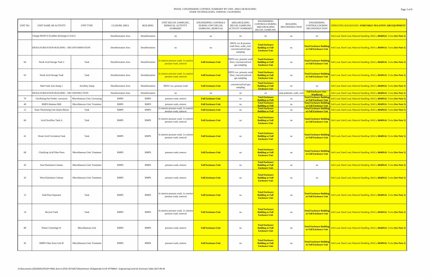
PHASE 1 ENGINEERING CONTROL SUMMARY BY UNIT, AREA OR BUILDINGEXIDE TECHNOLOGIES, VERNON, CALIFORNIA
Page 3 of 8
UNIT NO. UNIT NAME OR ACTIVITY UNIT TYPE CLOSURE AREA BUILDINGUNIT DECON, SAMPLING,
REMOVAL ACTIVITY SUMMARY
ENGINEERING CONTROLS DURING UNIT DECON, SAMPLING, REMOVAL
AREA/BUILDING DECON, SAMPLING
ACTIVITY SUMMARY
ENGINEERING CONTROLS DURING
AREA/BUILDING DECON, SAMPLING
BUILDING DECONSTRUCTION
ENGINEERING CONTROLS DURING DECONSTRUCTION
OPERATING BAGHOUSES / PORTABLE NEGATIVE AIR EQUIPMENT
Desulfurization Area Desulfurization na na no no no no Soft Lead, Hard Lead, Material Handling, MACs, MAPCO, Torits (See Note 5)
DESULFURIZATION BUILDING - DECONTAMINATION Desulfurization Area Desulfurization na na
HEPA vac & pressure wash floor, walls, roof; concrete/soil/soil gas
sampling
Total Enclosure Building or Full Enclosure Unit
naTotal Enclosure Building
or Full Enclosure UnitSoft Lead, Hard Lead, Material Handling, MACs, MAPCO, Torits (See Note 5)
64 North Acid Storage Tank 2 Tank Desulfurization Area Desulfurization3x interior pressure wash, 1x exterior
pressure wash, removalFull Enclosure Unit
HEPA vac, pressure wash floor; concrete/soil/soil
gas sampling
Total Enclosure Building or Full Enclosure Unit
naTotal Enclosure Building
or Full Enclosure UnitSoft Lead, Hard Lead, Material Handling, MACs, MAPCO, Torits (See Note 5)
65 North Acid Storage Tank Tank Desulfurization Area Desulfurization3x interior pressure wash, 1x exterior
pressure wash, removalFull Enclosure Unit
HEPA vac, pressure wash floor; concrete/soil/soil
gas sampling
Total Enclosure Building or Full Enclosure Unit
naTotal Enclosure Building
or Full Enclosure UnitSoft Lead, Hard Lead, Material Handling, MACs, MAPCO, Torits (See Note 5)
Mud Tank Area Sump 1 Ancillary Sump Desulfurization Area Desulfurization HEPA vac, pressure wash Full Enclosure Unitconcrete/soil/soil gas
sampling
Total Enclosure Building or Full Enclosure Unit
na na Soft Lead, Hard Lead, Material Handling, MACs, MAPCO, Torits (See Note 5)
DESULFURIZATION BUILDING - DECONSTRUCTION Desulfurization Area Desulfurization na na na na tank pedestals, walls, roofFull Enclosure Unit /
WindbreakSoft Lead, Hard Lead, Material Handling, MACs, MAPCO, Torits (See Note 5)
70 Oscillating Pan Feeder, conveyors Miscellaneous Unit; Conveying RMPS RMPS pressure wash, remove Full Enclosure Unit naTotal Enclosure Building or Full
naTotal Enclosure Building
or Full Enclosure UnitSoft Lead, Hard Lead, Material Handling, MACs, MAPCO, Torits (See Note 5)
40 RMPS Hammer Mill Miscellaneous Unit; Treatment RMPS RMPS pressure wash, remove Full Enclosure Unit naTotal Enclosure Building or Full
naTotal Enclosure Building
or Full Enclosure UnitSoft Lead, Hard Lead, Material Handling, MACs, MAPCO, Torits (See Note 5)
12 Paste Thickening Unit (Santa Maria) Tank RMPS RMPS1x interior pressure wash, 1x exterior
pressure wash, removalFull Enclosure Unit na
Total Enclosure Building or Full
naTotal Enclosure Building
or Full Enclosure UnitSoft Lead, Hard Lead, Material Handling, MACs, MAPCO, Torits (See Note 5)
66 Acid Overflow Tank A Tank RMPS RMPS3x interior pressure wash, 1x exterior
pressure wash, removalFull Enclosure Unit na
Total Enclosure Building or Full Enclosure Unit
naTotal Enclosure Building
or Full Enclosure UnitSoft Lead, Hard Lead, Material Handling, MACs, MAPCO, Torits (See Note 5)
41 Waste Acid Circulation Tank Tank RMPS RMPS3x interior pressure wash, 1x exterior
pressure wash, removalFull Enclosure Unit na
Total Enclosure Building or Full Enclosure Unit
naTotal Enclosure Building
or Full Enclosure UnitSoft Lead, Hard Lead, Material Handling, MACs, MAPCO, Torits (See Note 5)
68 Clarifying Acid Filter Press Miscellaneous Unit; Treatment RMPS RMPS pressure wash, remove Full Enclosure Unit naTotal Enclosure Building or Full Enclosure Unit
naTotal Enclosure Building
or Full Enclosure UnitSoft Lead, Hard Lead, Material Handling, MACs, MAPCO, Torits (See Note 5)
42 East Elutriation Column Miscellaneous Unit; Treatment RMPS RMPS pressure wash, remove Full Enclosure Unit naTotal Enclosure Building or Full Enclosure Unit
na na Soft Lead, Hard Lead, Material Handling, MACs, MAPCO, Torits (See Note 5)
43 West Elutriation Column Miscellaneous Unit; Treatment RMPS RMPS pressure wash, remove Full Enclosure Unit naTotal Enclosure Building or Full Enclosure Unit
na na Soft Lead, Hard Lead, Material Handling, MACs, MAPCO, Torits (See Note 5)
13 Sink/Float Separator Tank RMPS RMPS3x interior pressure wash, 1x exterior
pressure wash, removalFull Enclosure Unit na
Total Enclosure Building or Full Enclosure Unit
naTotal Enclosure Building
or Full Enclosure UnitSoft Lead, Hard Lead, Material Handling, MACs, MAPCO, Torits (See Note 5)
14 Recycle Tank Tank RMPS RMPS3x interior pressure wash, 1x exterior
pressure wash, removalFull Enclosure Unit na
Total Enclosure Building or Full Enclosure Unit
naTotal Enclosure Building
or Full Enclosure UnitSoft Lead, Hard Lead, Material Handling, MACs, MAPCO, Torits (See Note 5)
80 Plastic Centrifuge #1 Miscellaneous Unit RMPS RMPS pressure wash, remove Full Enclosure Unit naTotal Enclosure Building or Full Enclosure Unit
naTotal Enclosure Building
or Full Enclosure UnitSoft Lead, Hard Lead, Material Handling, MACs, MAPCO, Torits (See Note 5)
45 RMPS Filter Press Unit B Miscellaneous Unit; Treatment RMPS RMPS pressure wash, remove Full Enclosure Unit naTotal Enclosure Building or Full Enclosure Unit
naTotal Enclosure Building
or Full Enclosure UnitSoft Lead, Hard Lead, Material Handling, MACs, MAPCO, Torits (See Note 5)
Change MAPCO Scrubber discharge to Unit 6
D:\Documents (3)\EXIDE\CIP\CIP‐FINAL Sent to DTSC OCT2017\Attachment 14\Appendix G‐CIP ATTM#14 ‐ Engineering Controls Summary Table 2017‐09‐29
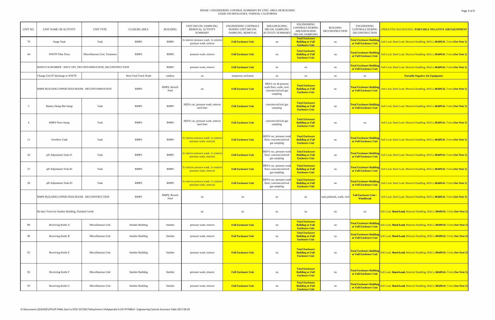
PHASE 1 ENGINEERING CONTROL SUMMARY BY UNIT, AREA OR BUILDINGEXIDE TECHNOLOGIES, VERNON, CALIFORNIA
Page 4 of 8
UNIT NO. UNIT NAME OR ACTIVITY UNIT TYPE CLOSURE AREA BUILDINGUNIT DECON, SAMPLING,
REMOVAL ACTIVITY SUMMARY
ENGINEERING CONTROLS DURING UNIT DECON, SAMPLING, REMOVAL
AREA/BUILDING DECON, SAMPLING
ACTIVITY SUMMARY
ENGINEERING CONTROLS DURING
AREA/BUILDING DECON, SAMPLING
BUILDING DECONSTRUCTION
ENGINEERING CONTROLS DURING DECONSTRUCTION
OPERATING BAGHOUSES / PORTABLE NEGATIVE AIR EQUIPMENT
79 Surge Tank Tank RMPS RMPS3x interior pressure wash, 1x exterior
pressure wash, removeFull Enclosure Unit na
Total Enclosure Building or Full Enclosure Unit
naTotal Enclosure Building
or Full Enclosure UnitSoft Lead, Hard Lead, Material Handling, MACs, MAPCO, Torits (See Note 5)
44 WWTP Filter Press Miscellaneous Unit; Treatment RMPS RMPS pressure wash, remove Full Enclosure Unit naTotal Enclosure Building or Full Enclosure Unit
naTotal Enclosure Building
or Full Enclosure UnitSoft Lead, Hard Lead, Material Handling, MACs, MAPCO, Torits (See Note 5)
RMPS pressure wash, remove Full Enclosure Unit na na naTotal Enclosure Building
or Full Enclosure UnitSoft Lead, Hard Lead, Material Handling, MACs, MAPCO, Torits (See Note 5)
Change Unit 87 discharge to WWTP West Yard Truck Wash outdoor na temporary enclosure na na na na Portable Negative Air Equipment
RMPS BUILDING/UPPER FEED ROOM - DECONTAMINATION RMPSRMPS, Reverb
Feedna Full Enclosure Unit
HEPA vac & pressure wash floor, walls, roof; concrete/soil/soil gas
sampling
Total Enclosure Building or Full Enclosure Unit
naTotal Enclosure Building
or Full Enclosure UnitSoft Lead, Hard Lead, Material Handling, MACs, MAPCO, Torits (See Note 5)
5 Battery Dump Bin Sump Tank RMPS RMPSHEPA vac, pressure wash, remove
steel linerFull Enclosure Unit
concrete/soil/soil gas sampling
Total Enclosure Building or Full Enclosure Unit
naTotal Enclosure Building
or Full Enclosure UnitSoft Lead, Hard Lead, Material Handling, MACs, MAPCO, Torits (See Note 5)
6 RMPS Floor Sump Tank RMPS RMPSHEPA vac, pressure wash, remove
steel linerFull Enclosure Unit
concrete/soil/soil gas sampling
Total Enclosure Building or Full Enclosure Unit
na na Soft Lead, Hard Lead, Material Handling, MACs, MAPCO, Torits (See Note 5)
11 Overflow Tank Tank RMPS RMPS3x interior pressure wash, 1x exterior
pressure wash, removalFull Enclosure Unit
HEPA vac, pressure wash floor; concrete/soil/soil
gas sampling
Total Enclosure Building or Full Enclosure Unit
naTotal Enclosure Building
or Full Enclosure UnitSoft Lead, Hard Lead, Material Handling, MACs, MAPCO, Torits (See Note 5)
26 pH Adjustment Tank #1 Tank RMPS RMPS3x interior pressure wash, 1x exterior
pressure wash, removalFull Enclosure Unit
HEPA vac, pressure wash floor; concrete/soil/soil
gas sampling
Total Enclosure Building or Full Enclosure Unit
naTotal Enclosure Building
or Full Enclosure UnitSoft Lead, Hard Lead, Material Handling, MACs, MAPCO, Torits (See Note 5)
27 pH Adjustment Tank #2 Tank RMPS RMPS3x interior pressure wash, 1x exterior
pressure wash, removalFull Enclosure Unit
HEPA vac, pressure wash floor; concrete/soil/soil
gas sampling
Total Enclosure Building or Full Enclosure Unit
naTotal Enclosure Building
or Full Enclosure UnitSoft Lead, Hard Lead, Material Handling, MACs, MAPCO, Torits (See Note 5)
28 pH Adjustment Tank #3 Tank RMPS RMPS3x interior pressure wash, 1x exterior
pressure wash, removalFull Enclosure Unit
HEPA vac, pressure wash floor; concrete/soil/soil
gas sampling
Total Enclosure Building or Full Enclosure Unit
naTotal Enclosure Building
or Full Enclosure UnitSoft Lead, Hard Lead, Material Handling, MACs, MAPCO, Torits (See Note 5)
RMPS BUILDING/UPPER FEED ROOM - DECONSTRUCTION RMPSRMPS, Reverb
Feedna na na na tank pedestals, walls, roof
Full Enclosure Unit / Windbreak
Soft Lead, Hard Lead, Material Handling, MACs, MAPCO, Torits (See Note 5)
Re-duct Torits for Smelter Building, Finished Goods na na na na na na Soft Lead, Hard Lead, Material Handling, MACs, MAPCO, Torits (See Note 5)
89 Receiving Kettle A Miscellaneous Unit Smelter Building Smelter pressure wash, remove Full Enclosure Unit naTotal Enclosure Building or Full Enclosure Unit
naTotal Enclosure Building
or Full Enclosure UnitSoft Lead, Hard Lead, Material Handling, MACs, MAPCO, Torits (See Note 5)
90 Receiving Kettle B Miscellaneous Unit Smelter Building Smelter pressure wash, remove Full Enclosure Unit naTotal Enclosure Building or Full Enclosure Unit
naTotal Enclosure Building
or Full Enclosure UnitSoft Lead, Hard Lead, Material Handling, MACs, MAPCO, Torits (See Note 5)
91 Receiving Kettle E Miscellaneous Unit Smelter Building Smelter pressure wash, remove Full Enclosure Unit naTotal Enclosure Building or Full Enclosure Unit
naTotal Enclosure Building
or Full Enclosure UnitSoft Lead, Hard Lead, Material Handling, MACs, MAPCO, Torits (See Note 5)
92 Receiving Kettle F Miscellaneous Unit Smelter Building Smelter pressure wash, remove Full Enclosure Unit naTotal Enclosure Building or Full Enclosure Unit
naTotal Enclosure Building
or Full Enclosure UnitSoft Lead, Hard Lead, Material Handling, MACs, MAPCO, Torits (See Note 5)
93 Receiving Kettle G Miscellaneous Unit Smelter Building Smelter pressure wash, remove Full Enclosure Unit naTotal Enclosure Building or Full Enclosure Unit
naTotal Enclosure Building
or Full Enclosure UnitSoft Lead, Hard Lead, Material Handling, MACs, MAPCO, Torits (See Note 5)
MAPCO SCRUBBER - SHUT OFF, DECONTAMINATION, DECONSTRUCTION
D:\Documents (3)\EXIDE\CIP\CIP‐FINAL Sent to DTSC OCT2017\Attachment 14\Appendix G‐CIP ATTM#14 ‐ Engineering Controls Summary Table 2017‐09‐29
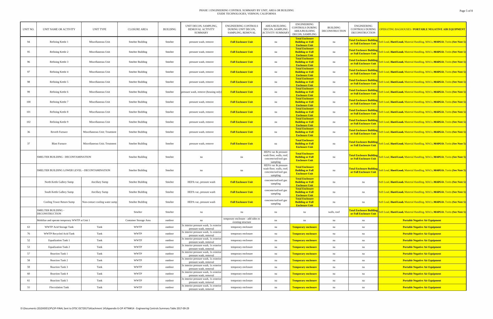
PHASE 1 ENGINEERING CONTROL SUMMARY BY UNIT, AREA OR BUILDINGEXIDE TECHNOLOGIES, VERNON, CALIFORNIA
Page 5 of 8
UNIT NO. UNIT NAME OR ACTIVITY UNIT TYPE CLOSURE AREA BUILDINGUNIT DECON, SAMPLING,
REMOVAL ACTIVITY SUMMARY
ENGINEERING CONTROLS DURING UNIT DECON, SAMPLING, REMOVAL
AREA/BUILDING DECON, SAMPLING
ACTIVITY SUMMARY
ENGINEERING CONTROLS DURING
AREA/BUILDING DECON, SAMPLING
BUILDING DECONSTRUCTION
ENGINEERING CONTROLS DURING DECONSTRUCTION
OPERATING BAGHOUSES / PORTABLE NEGATIVE AIR EQUIPMENT
94 Refining Kettle 1 Miscellaneous Unit Smelter Building Smelter pressure wash, remove Full Enclosure Unit naTotal Enclosure Building or Full Enclosure Unit
naTotal Enclosure Building
or Full Enclosure UnitSoft Lead, Hard Lead, Material Handling, MACs, MAPCO, Torits (See Note 5)
95 Refining Kettle 2 Miscellaneous Unit Smelter Building Smelter pressure wash, remove Full Enclosure Unit naTotal Enclosure Building or Full Enclosure Unit
naTotal Enclosure Building
or Full Enclosure UnitSoft Lead, Hard Lead, Material Handling, MACs, MAPCO, Torits (See Note 5)
96 Refining Kettle 3 Miscellaneous Unit Smelter Building Smelter pressure wash, remove Full Enclosure Unit naTotal Enclosure Building or Full Enclosure Unit
naTotal Enclosure Building
or Full Enclosure UnitSoft Lead, Hard Lead, Material Handling, MACs, MAPCO, Torits (See Note 5)
97 Refining Kettle 4 Miscellaneous Unit Smelter Building Smelter pressure wash, remove Full Enclosure Unit naTotal Enclosure Building or Full Enclosure Unit
naTotal Enclosure Building
or Full Enclosure UnitSoft Lead, Hard Lead, Material Handling, MACs, MAPCO, Torits (See Note 5)
98 Refining Kettle 5 Miscellaneous Unit Smelter Building Smelter pressure wash, remove Full Enclosure Unit naTotal Enclosure Building or Full Enclosure Unit
naTotal Enclosure Building
or Full Enclosure UnitSoft Lead, Hard Lead, Material Handling, MACs, MAPCO, Torits (See Note 5)
99 Refining Kettle 6 Miscellaneous Unit Smelter Building Smelter pressure wash, remove (housing only) Full Enclosure Unit naTotal Enclosure Building or Full Enclosure Unit
naTotal Enclosure Building
or Full Enclosure UnitSoft Lead, Hard Lead, Material Handling, MACs, MAPCO, Torits (See Note 5)
100 Refining Kettle 7 Miscellaneous Unit Smelter Building Smelter pressure wash, remove Full Enclosure Unit naTotal Enclosure Building or Full Enclosure Unit
naTotal Enclosure Building
or Full Enclosure UnitSoft Lead, Hard Lead, Material Handling, MACs, MAPCO, Torits (See Note 5)
101 Refining Kettle 8 Miscellaneous Unit Smelter Building Smelter pressure wash, remove Full Enclosure Unit naTotal Enclosure Building or Full Enclosure Unit
naTotal Enclosure Building
or Full Enclosure UnitSoft Lead, Hard Lead, Material Handling, MACs, MAPCO, Torits (See Note 5)
102 Refining Kettle 9 Miscellaneous Unit Smelter Building Smelter pressure wash, remove Full Enclosure Unit naTotal Enclosure Building or Full Enclosure Unit
naTotal Enclosure Building
or Full Enclosure UnitSoft Lead, Hard Lead, Material Handling, MACs, MAPCO, Torits (See Note 5)
36 Reverb Furnace Miscellaneous Unit; Treatment Smelter Building Smelter pressure wash, remove Full Enclosure Unit naTotal Enclosure Building or Full Enclosure Unit
naTotal Enclosure Building
or Full Enclosure UnitSoft Lead, Hard Lead, Material Handling, MACs, MAPCO, Torits (See Note 5)
37 Blast Furnace Miscellaneous Unit; Treatment Smelter Building Smelter pressure wash, remove Full Enclosure Unit naTotal Enclosure Building or Full Enclosure Unit
naTotal Enclosure Building
or Full Enclosure UnitSoft Lead, Hard Lead, Material Handling, MACs, MAPCO, Torits (See Note 5)
SMELTER BUILDING - DECONTAMINATION Smelter Building Smelter na na
HEPA vac & pressure wash floor, walls, roof; concrete/soil/soil gas
sampling
Total Enclosure Building or Full Enclosure Unit
naTotal Enclosure Building
or Full Enclosure UnitSoft Lead, Hard Lead, Material Handling, MACs, MAPCO, Torits (See Note 5)
SMELTER BUILDING LOWER LEVEL - DECONTAMINATION Smelter Building Smelter na na
HEPA vac & pressure wash floor, walls, roof; concrete/soil/soil gas
sampling
Total Enclosure Building or Full Enclosure Unit
naTotal Enclosure Building
or Full Enclosure UnitSoft Lead, Hard Lead, Material Handling, MACs, MAPCO, Torits (See Note 5)
North Kettle Gallery Sump Ancillary Sump Smelter Building Smelter HEPA vac, pressure wash Full Enclosure Unitconcrete/soil/soil gas
sampling
Total Enclosure Building or Full Enclosure Unit
na na Soft Lead, Hard Lead, Material Handling, MACs, MAPCO, Torits (See Note 5)
South Kettle Gallery Sump Ancillary Sump Smelter Building Smelter HEPA vac, pressure wash Full Enclosure Unitconcrete/soil/soil gas
sampling
Total Enclosure Building or Full Enclosure Unit
na na Soft Lead, Hard Lead, Material Handling, MACs, MAPCO, Torits (See Note 5)
Cooling Tower Return Sump Non-contact cooling water sump Smelter Building Smelter HEPA vac, pressure wash Full Enclosure Unitconcrete/soil/soil gas
sampling
Total Enclosure Building or Full Enclosure Unit
na na Soft Lead, Hard Lead, Material Handling, MACs, MAPCO, Torits (See Note 5)
SMELTER BUILDING - DECONSTRUCTION
Smelter Smelter na na na na walls, roofTotal Enclosure Building
or Full Enclosure UnitSoft Lead, Hard Lead, Material Handling, MACs, MAPCO, Torits (See Note 5)
Mobilize and operate temporary WWTP at Unit 1 Container Storage Area outdoor natemporary enclosure - add sides to
existing structurena na na na Portable Negative Air Equipment
63 WWTP Acid Storage Tank Tank WWTP outdoor3x interior pressure wash, 1x exterior
pressure wash, removaltemporary enclosure na Temporary enclosure na na Portable Negative Air Equipment
76 WWTP Recycled Acid Tank Tank WWTP outdoor3x interior pressure wash, 1x exterior
pressure wash, removaltemporary enclosure na Temporary enclosure na na Portable Negative Air Equipment
52 Equalization Tank 1 Tank WWTP outdoor3x interior pressure wash, 1x exterior
pressure wash, removaltemporary enclosure na Temporary enclosure na na Portable Negative Air Equipment
53 Equalization Tank 2 Tank WWTP outdoor3x interior pressure wash, 1x exterior
pressure wash, removaltemporary enclosure na Temporary enclosure na na Portable Negative Air Equipment
57 Reaction Tank 1 Tank WWTP outdoor3x interior pressure wash, 1x exterior
pressure wash, removaltemporary enclosure na Temporary enclosure na na Portable Negative Air Equipment
58 Reaction Tank 2 Tank WWTP outdoor3x interior pressure wash, 1x exterior
pressure wash, removaltemporary enclosure na Temporary enclosure na na Portable Negative Air Equipment
59 Reaction Tank 3 Tank WWTP outdoor3x interior pressure wash, 1x exterior
pressure wash, removaltemporary enclosure na Temporary enclosure na na Portable Negative Air Equipment
60 Reaction Tank 4 Tank WWTP outdoor3x interior pressure wash, 1x exterior
pressure wash, removaltemporary enclosure na Temporary enclosure na na Portable Negative Air Equipment
61 Reaction Tank 5 Tank WWTP outdoor3x interior pressure wash, 1x exterior
pressure wash, removaltemporary enclosure na Temporary enclosure na na Portable Negative Air Equipment
55 Flocculation Tank Tank WWTP outdoor3x interior pressure wash, 1x exterior
pressure wash, removaltemporary enclosure na Temporary enclosure na na Portable Negative Air Equipment
D:\Documents (3)\EXIDE\CIP\CIP‐FINAL Sent to DTSC OCT2017\Attachment 14\Appendix G‐CIP ATTM#14 ‐ Engineering Controls Summary Table 2017‐09‐29
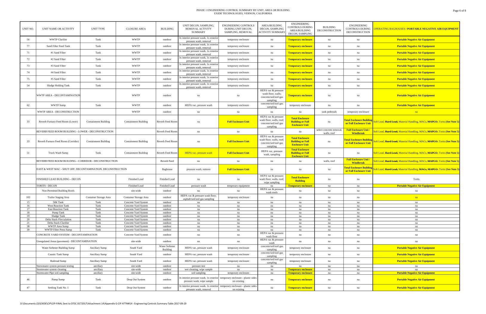
PHASE 1 ENGINEERING CONTROL SUMMARY BY UNIT, AREA OR BUILDINGEXIDE TECHNOLOGIES, VERNON, CALIFORNIA
Page 6 of 8
UNIT NO. UNIT NAME OR ACTIVITY UNIT TYPE CLOSURE AREA BUILDINGUNIT DECON, SAMPLING,
REMOVAL ACTIVITY SUMMARY
ENGINEERING CONTROLS DURING UNIT DECON, SAMPLING, REMOVAL
AREA/BUILDING DECON, SAMPLING
ACTIVITY SUMMARY
ENGINEERING CONTROLS DURING
AREA/BUILDING DECON, SAMPLING
BUILDING DECONSTRUCTION
ENGINEERING CONTROLS DURING DECONSTRUCTION
OPERATING BAGHOUSES / PORTABLE NEGATIVE AIR EQUIPMENT
56 WWTP Clarifier Tank WWTP outdoor3x interior pressure wash, 1x exterior
pressure wash, removaltemporary enclosure na Temporary enclosure na na Portable Negative Air Equipment
77 Sand Filter Feed Tank Tank WWTP outdoor3x interior pressure wash, 1x exterior
pressure wash, removaltemporary enclosure na Temporary enclosure na na Portable Negative Air Equipment
71 #1 Sand Filter Tank WWTP outdoor3x interior pressure wash, 1x exterior
pressure wash, removaltemporary enclosure na Temporary enclosure na na Portable Negative Air Equipment
72 #2 Sand Filter Tank WWTP outdoor3x interior pressure wash, 1x exterior
pressure wash, removaltemporary enclosure na Temporary enclosure na na Portable Negative Air Equipment
73 #3 Sand Filter Tank WWTP outdoor3x interior pressure wash, 1x exterior
pressure wash, removaltemporary enclosure na Temporary enclosure na na Portable Negative Air Equipment
74 #4 Sand Filter Tank WWTP outdoor3x interior pressure wash, 1x exterior
pressure wash, removaltemporary enclosure na Temporary enclosure na na Portable Negative Air Equipment
75 #5 Sand Filter Tank WWTP outdoor3x interior pressure wash, 1x exterior
pressure wash, removaltemporary enclosure na Temporary enclosure na na Portable Negative Air Equipment
54 Sludge Holding Tank Tank WWTP outdoor3x interior pressure wash, 1x exterior
pressure wash, removaltemporary enclosure na Temporary enclosure na na Portable Negative Air Equipment
WWTP AREA - DECONTAMINATION WWTP outdoor na na
HEPA vac & pressure wash floor, walls;
concrete/soil/soil gas sampling
Temporary enclosure na na Portable Negative Air Equipment
62 WWTP Sump Tank WWTP outdoor HEPA vac, pressure wash temporary enclosureconcrete/soil/soil gas
samplingtemporary enclosure na na Portable Negative Air Equipment
WWTP AREA - DECONSTRUCTION WWTP outdoor na na na na tank pedestals temporary enclosure na
33 Reverb Furnace Feed Room (Lower) Containment Building Containment Building Reverb Feed Room na Full Enclosure Unit
HEPA vac & pressure wash floor, walls, roof; concrete/soil/soil gas
sampling
Total Enclosure Building or Full Enclosure Unit
naTotal Enclosure Building
or Full Enclosure UnitSoft Lead, Hard Lead, Material Handling, MACs, MAPCO, Torits (See Note 5)
REVERB FEED ROOM BUILDING - LOWER - DECONSTRUCTION Reverb Feed Room na na na naselect concrete removal,
walls, roofFull Enclosure Unit /
WindbreakSoft Lead, Hard Lead, Material Handling, MACs, MAPCO, Torits (See Note 5)
33 Reverb Furnace Feed Room (Corridor) Containment Building Containment Building Reverb Feed Room na Full Enclosure Unit
HEPA vac & pressure wash floor, walls, roof; concrete/soil/soil gas
sampling
Total Enclosure Building or Full Enclosure Unit
naTotal Enclosure Building
or Full Enclosure UnitSoft Lead, Hard Lead, Material Handling, MACs, MAPCO, Torits (See Note 5)
51 Truck Wash Sump Tank Containment Building Reverb Feed Room HEPA vac, pressure wash Full Enclosure UnitHEPA vac, pressure
wash, sampling
Total Enclosure Building or Full Enclosure Unit
na na Soft Lead, Hard Lead, Material Handling, MACs, MAPCO, Torits (See Note 5)
REVERB FEED ROOM BUILDING - CORRIDOR - DECONSTRUCTION Reverb Feed na na na na walls, roofFull Enclosure Unit /
WindbreakSoft Lead, Hard Lead, Material Handling, MACs, MAPCO, Torits (See Note 5)
Baghouse pressure wash, remove Full Enclosure Unit na na naTotal Enclosure Building
or Full Enclosure UnitSoft Lead, Hard Lead, Material Handling, MACs, MAPCO, Torits (See Note 5)
FINISHED LEAD BUILDING - DECON Finished Lead Finished Lead na naHEPA vac & pressure wash floor, walls, roof;
wipe sampling
Total Enclosure Building
na na Torits
TORITS - DECON Finished Lead Finished Lead pressure wash temporary equipment na Temporary enclosure na na Portable Negative Air Equipment
Non-Permitted Building Roofs site-wide outdoor na naHEPA vac & pressure
wash roofsna na na na
103 Trailer Staging Area Container Storage Area Container Storage Area outdoorHEPA vac & pressure wash floor;
asphalt/soil/soil gas samplingtemporary enclosure na na na na na
15 50K Tank Tank Concrete Yard System outdoor na na na na na na na16 West Reaction Tank Tank Concrete Yard System outdoor na na na na na na na17 East Reaction Tank Tank Concrete Yard System outdoor na na na na na na na18 Pump Tank Tank Concrete Yard System outdoor na na na na na na na19 Sludge Tank Tank Concrete Yard System outdoor na na na na na na na20 Delta Stack Flocculation Tank Concrete Yard System outdoor na na na na na na na21 Delta Stack Clarifier Tank Concrete Yard System outdoor na na na na na na na38 WWTP Area Sump Tank Concrete Yard System outdoor na na na na na na na39 WWTP Filter Press Sump Tank Concrete Yard System outdoor na na na na na na na
CONCRETE YARD SYSTEM - DECONTAMINATION Concrete Yard System outdoor na naHEPA vac & pressure
wash floorna na na na
Unregulated Areas (pavement) - DECONTAMINATION site-wide outdoor na naHEPA vac & pressure
washna na na na
Water Softener Building Sump Ancillary Sump South YardWater Softener
BuildingHEPA vac, pressure wash temporary enclosure
concrete/soil/soil gas sampling
temporary enclosure na na Portable Negative Air Equipment
Caustic Tank Sump Ancillary Sump South Yard outdoor HEPA vac, pressure wash temporary enclosureconcrete/soil/soil gas
samplingtemporary enclosure na na Portable Negative Air Equipment
Railroad Sump Ancillary Sump South Yard outdoor HEPA vac, pressure wash temporary enclosureconcrete/soil/soil gas
samplingtemporary enclosure na na Portable Negative Air Equipment
Storwmater system pressure testing ancillary site-wide outdoor pressure test na na na na na naStormwater system cleaning ancillary site-wide outdoor wet cleaning, wipe sample na na Temporary enclosure na na naStormwater Pipe soil sampling ancillary site-wide outdoor soil sampling temporary enclosure na Temporary enclosure na na Portable Negative Air Equipment
46 Pump Sump Tank Drop Out System outdoor3x interior pressure wash, 1x exterior
pressure wash, wipe sampletemporary enclosure - plastic sides
on existingna Temporary enclosure na na Portable Negative Air Equipment
47 Settling Tank No. 1 Tank Drop Out System outdoor3x interior pressure wash, 1x exterior
pressure wash, removaltemporary enclosure - plastic sides
on existingna Temporary enclosure na na Portable Negative Air Equipment
EAST & WEST MAC - SHUT OFF, DECONTAMINATION, DECONSTRUCTION
D:\Documents (3)\EXIDE\CIP\CIP‐FINAL Sent to DTSC OCT2017\Attachment 14\Appendix G‐CIP ATTM#14 ‐ Engineering Controls Summary Table 2017‐09‐29
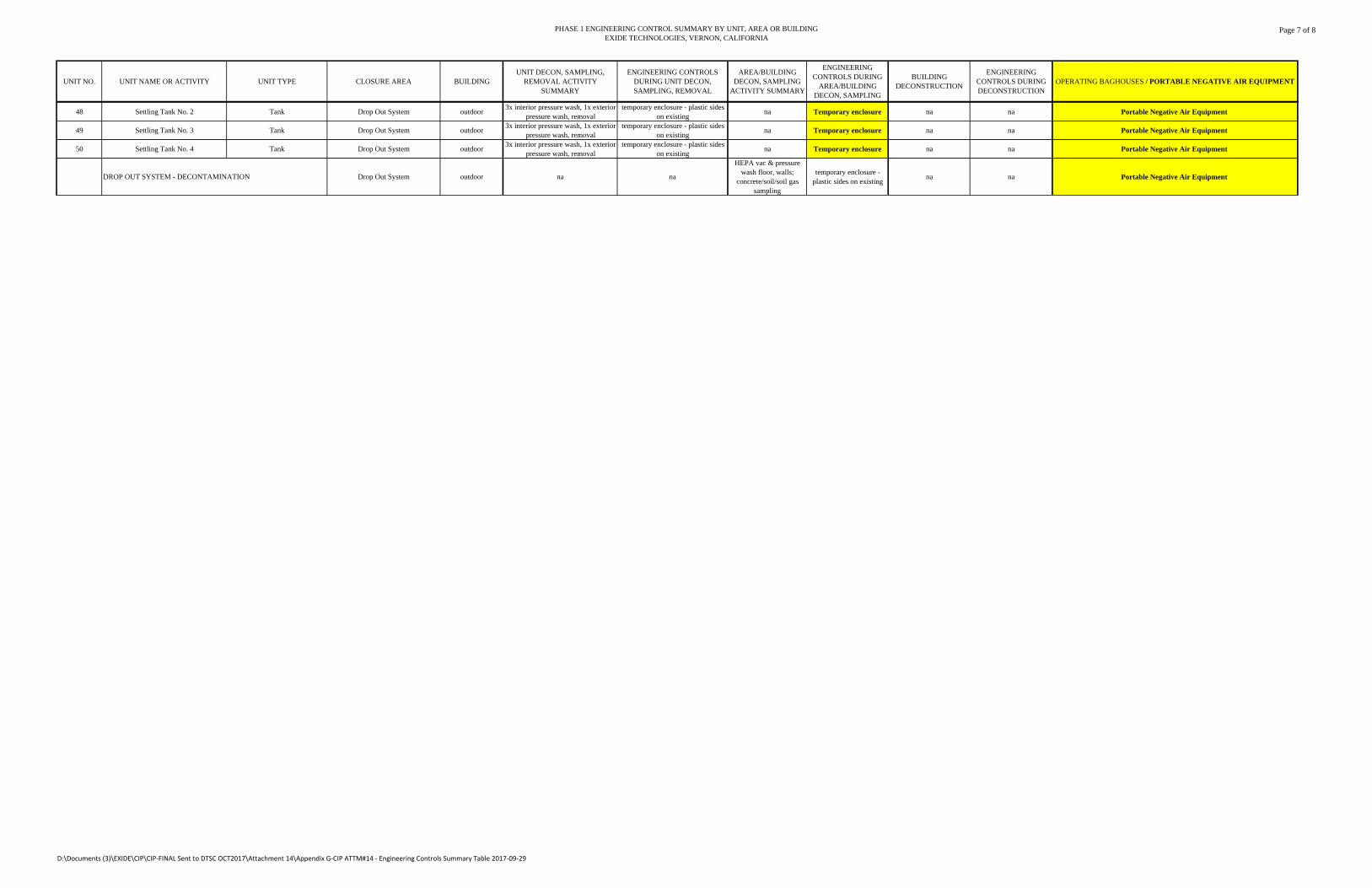
PHASE 1 ENGINEERING CONTROL SUMMARY BY UNIT, AREA OR BUILDINGEXIDE TECHNOLOGIES, VERNON, CALIFORNIA
Page 7 of 8
UNIT NO. UNIT NAME OR ACTIVITY UNIT TYPE CLOSURE AREA BUILDINGUNIT DECON, SAMPLING,
REMOVAL ACTIVITY SUMMARY
ENGINEERING CONTROLS DURING UNIT DECON, SAMPLING, REMOVAL
AREA/BUILDING DECON, SAMPLING
ACTIVITY SUMMARY
ENGINEERING CONTROLS DURING
AREA/BUILDING DECON, SAMPLING
BUILDING DECONSTRUCTION
ENGINEERING CONTROLS DURING DECONSTRUCTION
OPERATING BAGHOUSES / PORTABLE NEGATIVE AIR EQUIPMENT
48 Settling Tank No. 2 Tank Drop Out System outdoor3x interior pressure wash, 1x exterior
pressure wash, removaltemporary enclosure - plastic sides
on existingna Temporary enclosure na na Portable Negative Air Equipment
49 Settling Tank No. 3 Tank Drop Out System outdoor3x interior pressure wash, 1x exterior
pressure wash, removaltemporary enclosure - plastic sides
on existingna Temporary enclosure na na Portable Negative Air Equipment
50 Settling Tank No. 4 Tank Drop Out System outdoor3x interior pressure wash, 1x exterior
pressure wash, removaltemporary enclosure - plastic sides
on existingna Temporary enclosure na na Portable Negative Air Equipment
DROP OUT SYSTEM - DECONTAMINATION Drop Out System outdoor na na
HEPA vac & pressure wash floor, walls;
concrete/soil/soil gas sampling
temporary enclosure - plastic sides on existing
na na Portable Negative Air Equipment
D:\Documents (3)\EXIDE\CIP\CIP‐FINAL Sent to DTSC OCT2017\Attachment 14\Appendix G‐CIP ATTM#14 ‐ Engineering Controls Summary Table 2017‐09‐29
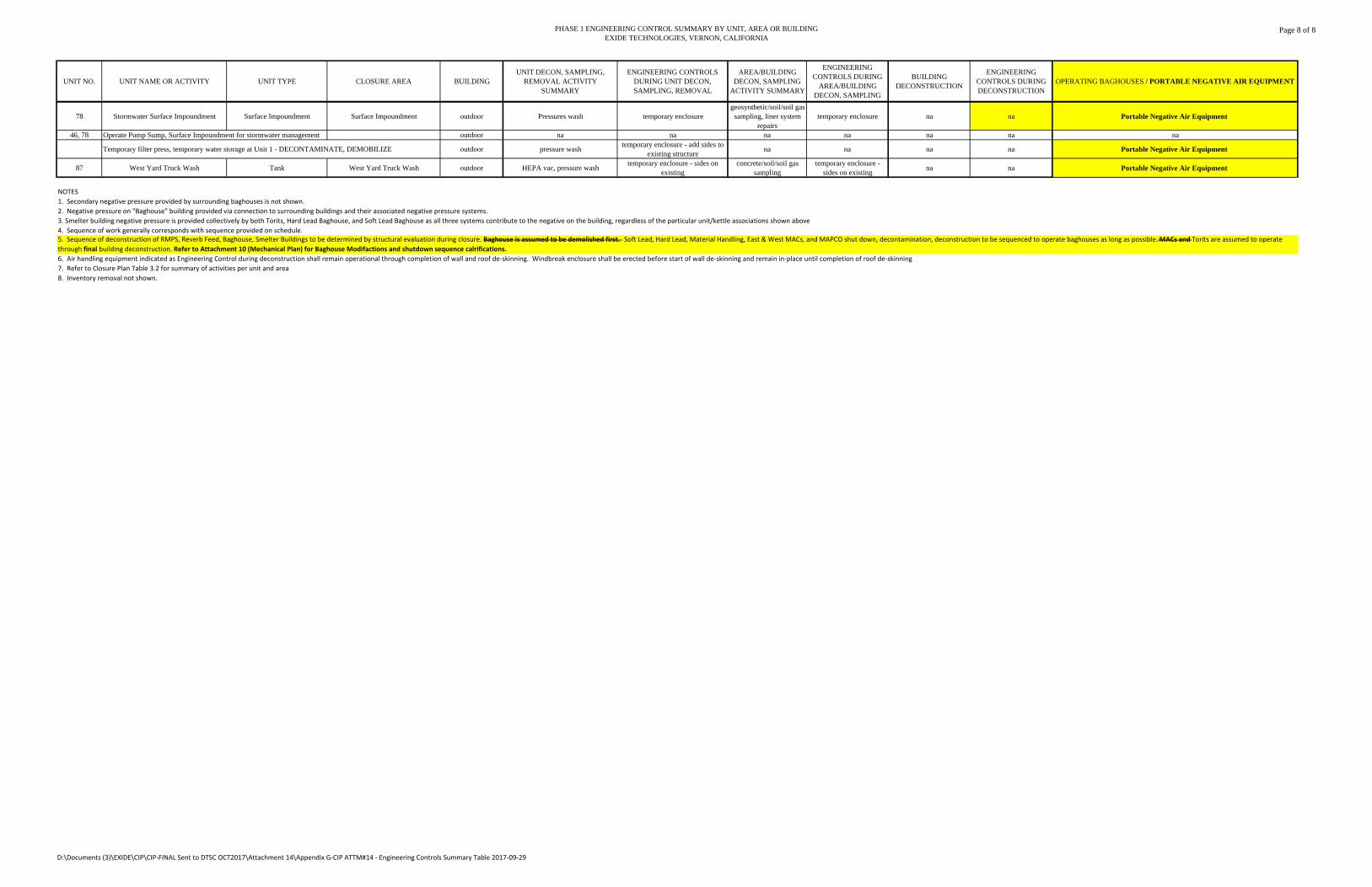
PHASE 1 ENGINEERING CONTROL SUMMARY BY UNIT, AREA OR BUILDINGEXIDE TECHNOLOGIES, VERNON, CALIFORNIA
Page 8 of 8
UNIT NO. UNIT NAME OR ACTIVITY UNIT TYPE CLOSURE AREA BUILDINGUNIT DECON, SAMPLING,
REMOVAL ACTIVITY SUMMARY
ENGINEERING CONTROLS DURING UNIT DECON, SAMPLING, REMOVAL
AREA/BUILDING DECON, SAMPLING
ACTIVITY SUMMARY
ENGINEERING CONTROLS DURING
AREA/BUILDING DECON, SAMPLING
BUILDING DECONSTRUCTION
ENGINEERING CONTROLS DURING DECONSTRUCTION
OPERATING BAGHOUSES / PORTABLE NEGATIVE AIR EQUIPMENT
78 Stormwater Surface Impoundment Surface Impoundment Surface Impoundment outdoor Pressures wash temporary enclosuregeosynthetic/soil/soil gas
sampling, liner system repairs
temporary enclosure na na Portable Negative Air Equipment
46, 78 Operate Pump Sump, Surface Impoundment for stormwater management outdoor na na na na na na na
Temporary filter press, temporary water storage at Unit 1 - DECONTAMINATE, DEMOBILIZE outdoor pressure washtemporary enclosure - add sides to
existing structurena na na na Portable Negative Air Equipment
87 West Yard Truck Wash Tank West Yard Truck Wash outdoor HEPA vac, pressure washtemporary enclosure - sides on
existingconcrete/soil/soil gas
samplingtemporary enclosure -
sides on existingna na Portable Negative Air Equipment
NOTES
1. Secondary negative pressure provided by surrounding baghouses is not shown.
2. Negative pressure on "Baghouse" building provided via connection to surrounding buildings and their associated negative pressure systems.
3. Smelter building negative pressure is provided collectively by both Torits, Hard Lead Baghouse, and Soft Lead Baghouse as all three systems contribute to the negative on the building, regardless of the particular unit/kettle associations shown above
4. Sequence of work generally corresponds with sequence provided on schedule.
6. Air handling equipment indicated as Engineering Control during deconstruction shall remain operational through completion of wall and roof de‐skinning. Windbreak enclosure shall be erected before start of wall de‐skinning and remain in‐place until completion of roof de‐skinning
7. Refer to Closure Plan Table 3.2 for summary of activities per unit and area.
8. Inventory removal not shown.
5. Sequence of deconstruction of RMPS, Reverb Feed, Baghouse, Smelter Buildings to be determined by structural evaluation during closure. Baghouse is assumed to be demolished first. Soft Lead, Hard Lead, Material Handling, East & West MACs, and MAPCO shut down, decontamination, deconstruction to be sequenced to operate baghouses as long as possible.MACs and Torits are assumed to operate
through final building deconstruction. Refer to Attachment 10 (Mechanical Plan) for Baghouse Modifactions and shutdown sequence calrifications.
D:\Documents (3)\EXIDE\CIP\CIP‐FINAL Sent to DTSC OCT2017\Attachment 14\Appendix G‐CIP ATTM#14 ‐ Engineering Controls Summary Table 2017‐09‐29
f:\projects\2013\20132993 - exide vernon permitting assistance\sec files\reports\closure plan 11-2015\appendix g\appendix g 11 10 2015.docx
INSPECTION FORMS
(REFER TO ATTACHMENT 2 OF THE CLOSURE IMPLEMENTATION PLAN:
ATTACHMENT 2-4: PRE-LOADING CHECKLIST ATTACHMENT 2-5: TRUCK INSPECTION AND
DECONTAMINATION CHECKLIST
f:\projects\2013\20132993 - exide vernon permitting assistance\sec files\reports\closure plan 11-2015\appendix g\appendix g 11 10 2015.docx
MATERIAL INFORMATIONS SAFETY DATA SHEETS

DescriptionSL 1™ is a one-componentnonpriming, self-leveling elastomericpolyurethane designed for expansionjoints in concrete floors and decks.Use it where flexibility as well asabrasion and puncture resistance arerequired.
Yield
See page 3 for charts.
Packaging
2 gallon pails (7.6 L)
825 ml cartridges, 12 cartridges per carton
300 ml cartridges in limestone, 30 cartridges per carton
20 oz (590 ml) ProPaks in limestone,20 ProPaks per carton
Shelf Life
In bulk: 6 months when properlystored
Cartridges and ProPaks: 1 year whenproperly stored
Storage
Store in unopened containers in acool, clean, dry area. Storing atelevated temperatures will reduceshelf life.
Color
Limestone, gray or stone
Where to UseAPPLICATION
• Expansion joints
• Pavers
• Plaza decks
• Industrial floors
• Driveways
• Sidewalks
• Decks
• Parking areas
• Pitch pans
LOCATION
• Horizontal
• Interior and exterior
SUBSTRATE
• Concrete
• Metal
How to ApplyJoint Preparation
1. The number of joints and the joint width shouldbe designed not to exceed ±25% movement.
2. The depth of the sealant should be 1/2 the widthof the joint. The maximum depth is 3/8" (10 mm) and the minimum is 1/4" (6 mm).Maximum recommended joint width is 1-1/2" (38mm).
3. In deep joints, sealant depth must be controlledwith Backer-Rod (closed cell only) or Expansion-JointFiller (see Form Nos. 1017927 and 1017916). Othercaulks should not be used as fillers. Do not primeBacker-Rod or Expansion Joint Filler. Do not puncturebacker-rod; it may cause bubbling.
4. Caulking and sealing should be performed whentemperatures are above 40° F (4° C). Application tomoist surfaces will adversely affect adhesion.Application may proceed as low as 20° F (-7° C)only if substrates are clean and completely free ofmoisture or frost.
Features Benefits• Movement capability of ±25% Expands and contracts with joint movement
• Abrasion resistant Provides longer wearing and durability
• Easy to gun Installs quickly
• Variety of types and sizes of packaging Reduces jobsite waste
• Nonpriming on most surfaces Offers excellent adhesion
• Self levels Requires no tooling
• Wide application-temperature range Suitable for all climates
• Excellent weatherability Offers long-lasting performance
SONOLASTIC® SL 1™
One-component elastomeric, self-leveling polyurethane sealant
PRODUCT DATA
JointSealants
07 92 007
®
36
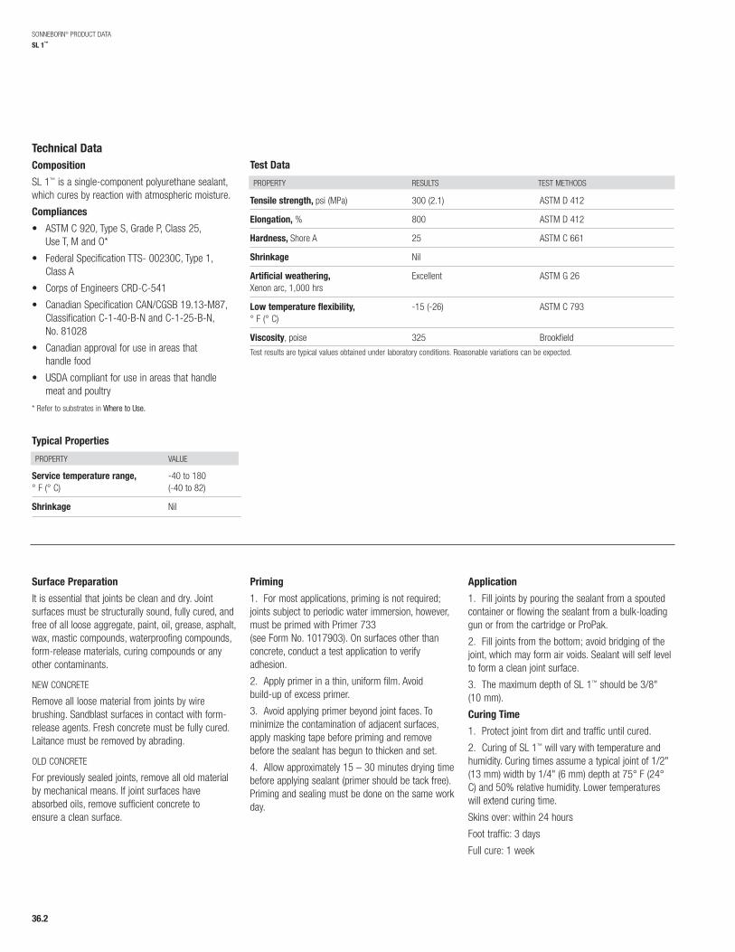
Technical DataComposition
SL 1™ is a single-component polyurethane sealant,which cures by reaction with atmospheric moisture.
Compliances
• ASTM C 920, Type S, Grade P, Class 25, Use T, M and O*
• Federal Specification TTS- 00230C, Type 1, Class A
• Corps of Engineers CRD-C-541
• Canadian Specification CAN/CGSB 19.13-M87,Classification C-1-40-B-N and C-1-25-B-N, No. 81028
• Canadian approval for use in areas that handle food
• USDA compliant for use in areas that handlemeat and poultry
* Refer to substrates in Where to Use.
Typical Properties
Test Data
PROPERTY RESULTS TEST METHODS
SONNEBORN® PRODUCT DATA
SL 1™
PROPERTY VALUE
Service temperature range, -40 to 180 ° F (° C) (-40 to 82)
Shrinkage Nil
Tensile strength, psi (MPa) 300 (2.1) ASTM D 412
Elongation, % 800 ASTM D 412
Hardness, Shore A 25 ASTM C 661
Shrinkage Nil
Artificial weathering, Excellent ASTM G 26Xenon arc, 1,000 hrs
Low temperature flexibility, -15 (-26) ASTM C 793° F (° C)
Viscosity, poise 325 BrookfieldTest results are typical values obtained under laboratory conditions. Reasonable variations can be expected.
Surface Preparation
It is essential that joints be clean and dry. Jointsurfaces must be structurally sound, fully cured, andfree of all loose aggregate, paint, oil, grease, asphalt,wax, mastic compounds, waterproofing compounds,form-release materials, curing compounds or anyother contaminants.
NEW CONCRETE
Remove all loose material from joints by wirebrushing. Sandblast surfaces in contact with form-release agents. Fresh concrete must be fully cured.Laitance must be removed by abrading.
OLD CONCRETE
For previously sealed joints, remove all old materialby mechanical means. If joint surfaces haveabsorbed oils, remove sufficient concrete toensure a clean surface.
Priming
1. For most applications, priming is not required;joints subject to periodic water immersion, however,must be primed with Primer 733 (see Form No. 1017903). On surfaces other thanconcrete, conduct a test application to verifyadhesion.
2. Apply primer in a thin, uniform film. Avoid build-up of excess primer.
3. Avoid applying primer beyond joint faces. Tominimize the contamination of adjacent surfaces,apply masking tape before priming and removebefore the sealant has begun to thicken and set.
4. Allow approximately 15 – 30 minutes drying timebefore applying sealant (primer should be tack free).Priming and sealing must be done on the same workday.
Application
1. Fill joints by pouring the sealant from a spoutedcontainer or flowing the sealant from a bulk-loadinggun or from the cartridge or ProPak.
2. Fill joints from the bottom; avoid bridging of thejoint, which may form air voids. Sealant will self levelto form a clean joint surface.
3. The maximum depth of SL 1™ should be 3/8"(10 mm).
Curing Time
1. Protect joint from dirt and traffic until cured.
2. Curing of SL 1™ will vary with temperature andhumidity. Curing times assume a typical joint of 1/2"(13 mm) width by 1/4" (6 mm) depth at 75° F (24°C) and 50% relative humidity. Lower temperatureswill extend curing time.
Skins over: within 24 hours
Foot traffic: 3 days
Full cure: 1 week
36.2
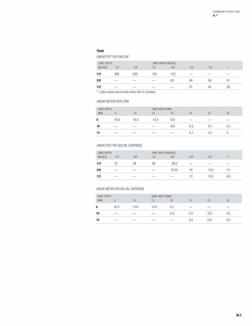
SONNEBORN® PRODUCT DATA
SL 1™
Yield
LINEAR FEET PER GALLON*
JOINT DEPTH JOINT WIDTH (INCHES)(INCHES) 1/4 3/8 1/2 5/8 3/4 7/8 1
JOINT DEPTH JOINT WIDTH (MM)(MM) 6 10 13 16 19 22 25
1/4 308 205 154 122 — — —
3/8 — — — 82 68 58 51
1/2 — — — — 51 44 38* 1 gallon equals approximately twelve 300 ml cartridges.
6 24.8 16.5 12.4 9.8 — — —
10 — — — 6.6 5.5 4.7 4.1
13 — — — — 4.1 3.5 3
LINEAR METERS PER LITER
JOINT DEPTH JOINT WIDTH (INCHES)(INCHES) 1/4" 3/8” 1/2” 5/8” 3/4” 7/8” 1”
1/4 72 48 36 28.5 — — —
3/8 — — — 19.25 16 13.5 12
1/2 — — — — 12 10.2 8.8
LINEAR FEET PER 825 ML CARTRIDGE
JOINT DEPTH JOINT WIDTH (MM)(MM) 6 10 13 16 19 22 25
6 20.5 13.6 10.2 8.1 — — —
10 — — — 5.4 4.5 3.9 3.4
13 — — — — 3.4 2.9 2.5
LINEAR METER PER 825 ML CARTRIDGE
36.3
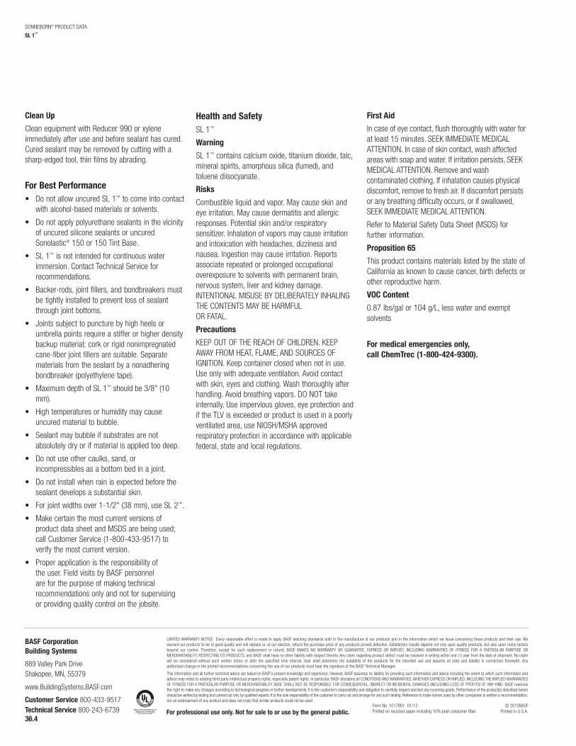
Clean Up
Clean equipment with Reducer 990 or xyleneimmediately after use and before sealant has cured.Cured sealant may be removed by cutting with asharp-edged tool, thin films by abrading.
For Best Performance• Do not allow uncured SL 1™ to come into contact
with alcohol-based materials or solvents.
• Do not apply polyurethane sealants in the vicinityof uncured silicone sealants or uncuredSonolastic® 150 or 150 Tint Base.
• SL 1™ is not intended for continuous waterimmersion. Contact Technical Service forrecommendations.
• Backer-rods, joint fillers, and bondbreakers mustbe tightly installed to prevent loss of sealantthrough joint bottoms.
• Joints subject to puncture by high heels orumbrella points require a stiffer or higher densitybackup material; cork or rigid nonimpregnatedcane-fiber joint fillers are suitable. Separatematerials from the sealant by a nonadheringbondbreaker (polyethylene tape).
• Maximum depth of SL 1™ should be 3/8" (10mm).
• High temperatures or humidity may causeuncured material to bubble.
• Sealant may bubble if substrates are notabsolutely dry or if material is applied too deep.
• Do not use other caulks, sand, orincompressibles as a bottom bed in a joint.
• Do not install when rain is expected before thesealant develops a substantial skin.
• For joint widths over 1-1/2" (38 mm), use SL 2™.
• Make certain the most current versions ofproduct data sheet and MSDS are being used; call Customer Service (1-800-433-9517) to verify the most current version.
• Proper application is the responsibility of the user. Field visits by BASF personnelare for the purpose of making technicalrecommendations only and not for supervisingor providing quality control on the jobsite.
Health and SafetySL 1™
Warning
SL 1™ contains calcium oxide, titanium dioxide, talc,mineral spirits, amorphous silica (fumed), andtoluene diisocyanate.
Risks
Combustible liquid and vapor. May cause skin andeye irritation. May cause dermatitis and allergicresponses. Potential skin and/or respiratorysensitizer. Inhalation of vapors may cause irritationand intoxication with headaches, dizziness andnausea. Ingestion may cause irritation. Reportsassociate repeated or prolonged occupationaloverexposure to solvents with permanent brain,nervous system, liver and kidney damage.INTENTIONAL MISUSE BY DELIBERATELY INHALINGTHE CONTENTS MAY BE HARMFULOR FATAL.
Precautions
KEEP OUT OF THE REACH OF CHILDREN. KEEPAWAY FROM HEAT, FLAME, AND SOURCES OFIGNITION. Keep container closed when not in use.Use only with adequate ventilation. Avoid contactwith skin, eyes and clothing. Wash thoroughly afterhandling. Avoid breathing vapors. DO NOT takeinternally. Use impervious gloves, eye protection andif the TLV is exceeded or product is used in a poorlyventilated area, use NIOSH/MSHA approvedrespiratory protection in accordance with applicablefederal, state and local regulations.
First Aid
In case of eye contact, flush thoroughly with water forat least 15 minutes. SEEK IMMEDIATE MEDICALATTENTION. In case of skin contact, wash affectedareas with soap and water. If irritation persists, SEEKMEDICAL ATTENTION. Remove and washcontaminated clothing. If inhalation causes physicaldiscomfort, remove to fresh air. If discomfort persistsor any breathing difficulty occurs, or if swallowed,SEEK IMMEDIATE MEDICAL ATTENTION.
Refer to Material Safety Data Sheet (MSDS) forfurther information.
Proposition 65
This product contains materials listed by the state ofCalifornia as known to cause cancer, birth defects orother reproductive harm.
VOC Content
0.87 lbs/gal or 104 g/L, less water and exemptsolvents
For medical emergencies only, call ChemTrec (1-800-424-9300).
SONNEBORN® PRODUCT DATA
SL 1™
BASF CorporationBuilding Systems
889 Valley Park DriveShakopee, MN, 55379
www.BuildingSystems.BASF.com
Customer Service 800-433-9517Technical Service 800-243-6739 For professional use only. Not for sale to or use by the general public.
© 2012BASFPrinted in U.S.A.
LIMITED WARRANTY NOTICE Every reasonable effort is made to apply BASF exacting standards both in the manufacture of our products and in the information which we issue concerning these products and their use. We warrant our products to be of good quality and will replace or, at our election, refund the purchase price of any products proved defective. Satisfactory results depend not only upon quality products, but also upon many factorsbeyond our control. Therefore, except for such replacement or refund, BASF MAKES NO WARRANTY OR GUARANTEE, EXPRESS OR IMPLIED, INCLUDING WARRANTIES OF FITNESS FOR A PARTICULAR PURPOSE OR MERCHANTABILITY, RESPECTING ITS PRODUCTS, and BASF shall have no other liability with respect thereto. Any claim regarding product defect must be received in writing within one (1) year from the date of shipment. No claimwill be considered without such written notice or after the specified time interval. User shall determine the suitability of the products for the intended use and assume all risks and liability in connection therewith. Any authorized change in the printed recommendations concerning the use of our products must bear the signature of the BASF Technical Manager.
This information and all further technical advice are based on BASF’s present knowledge and experience. However, BASF assumes no liability for providing such information and advice including the extent to which such information andadvice may relate to existing third party intellectual property rights, especially patent rights. In particular, BASF disclaims all CONDITIONS AND WARRANTIES, WHETHER EXPRESS OR IMPLIED, INCLUDING THE IMPLIED WARRANTIESOF FITNESS FOR A PARTICULAR PURPOSE OR MERCHANTABILITY. BASF SHALL NOT BE RESPONSIBLE FOR CONSEQUENTIAL, INDIRECT OR INCIDENTAL DAMAGES (INCLUDING LOSS OF PROFITS) OF ANY KIND. BASF reservesthe right to make any changes according to technological progress or further developments. It is the customer’s responsibility and obligation to carefully inspect and test any incoming goods. Performance of the product(s) described hereinshould be verified by testing and carried out only by qualified experts. It is the sole responsibility of the customer to carry out and arrange for any such testing. Reference to trade names used by other companies is neither a recommendation,nor an endorsement of any product and does not imply that similar products could not be used.
Form No. 1017901 01/12Printed on recycled paper including 10% post-consumer fiber.
36.4
Safety Data Sheet MasterSeal SL 1 stn also SL1 STN Revision date : 2015/07/08 Page: 1/12 Version: 2.1 (30606244/SDS_GEN_US/EN)
1. Identification
Product identifier used on the label
MasterSeal SL 1 stn also SL1 STN
Recommended use of the chemical and restriction on use Recommended use*: for industrial and professional users * The “Recommended use” identified for this product is provided solely to comply with a Federal requirement and is not part of the seller's published specification. The terms of this Safety Data Sheet (SDS) do not create or infer any warranty, express or implied, including by incorporation into or reference in the seller's sales agreement.
Details of the supplier of the safety data sheet Company: BASF CORPORATION 100 Park Avenue Florham Park, NJ 07932, USA
Telephone: +1 973 245-6000
Emergency telephone number CHEMTREC: 1-800-424-9300 BASF HOTLINE: 1-800-832-HELP (4357)
Other means of identification Chemical family: No data available.
2. Hazards Identification
According to Regulation 2012 OSHA Hazard Communication Standard; 29 CFR Part 1910.1200
Classification of the product Flam. Liq. 4 Flammable liquids Skin Corr./Irrit. 2 Skin corrosion/irritation Eye Dam./Irrit. 2A Serious eye damage/eye irritation Resp. Sens. 1 Respiratory sensitization Skin Sens. 1 Skin sensitization Carc. 2 Carcinogenicity Repr. 2 (unborn child) Reproductive toxicity STOT RE 1 Specific target organ toxicity — repeated
exposure
Safety Data Sheet MasterSeal SL 1 stn also SL1 STN Revision date : 2015/07/08 Page: 2/12 Version: 2.1 (30606244/SDS_GEN_US/EN)
Label elements Pictogram:
Signal Word: Danger Hazard Statement: H227 Combustible liquid. H319 Causes serious eye irritation. H315 Causes skin irritation. H334 May cause allergy or asthma symptoms or breathing difficulties if
inhaled. H317 May cause an allergic skin reaction. H351 Suspected of causing cancer. H361 Suspected of damaging the unborn child. H372 Causes damage to organs (Central nervous system) through prolonged
or repeated exposure. Precautionary Statements (Prevention): P280 Wear protective gloves/protective clothing/eye protection/face
protection. P260 Do not breathe dust/gas/mist/vapours. P201 Obtain special instructions before use. P210 Keep away from heat, hot surfaces, sparks, open flames and other
ignition sources. No smoking. P202 Do not handle until all safety precautions have been read and
understood. P284 [In case of inadequate ventilation] wear respiratory protection. P270 Do not eat, drink or smoke when using this product. P264 Wash with plenty of water and soap thoroughly after handling. P272 Contaminated work clothing should not be allowed out of the workplace. Precautionary Statements (Response): P305 + P351 + P338 IF IN EYES: Rinse cautiously with water for several minutes. Remove
contact lenses, if present and easy to do. Continue rinsing. P304 + P341 + P311 IF INHALED: If breathing is difficult, remove to fresh air and keep at rest
in a position comfortable for breathing. Call a POISON CENTER or doctor/physician.
P308 + P311 IF exposed or concerned: Call a POISON CENTER or doctor/physician. P303 + P352 IF ON SKIN (or hair): Wash with plenty of soap and water. P333 + P311 If skin irritation or rash occurs: Call a POISON CENTER or
doctor/physician. P332 + P313 If skin irritation occurs: Get medical advice/attention. P362 + P364 Take off contaminated clothing and wash before reuse. P337 + P311 If eye irritation persists: Call a POISON CENTER or doctor/physician. P370 + P378 In case of fire: Use alcohol-resistant foam, carbon dioxide, dry powder
or water spray for extinction. Precautionary Statements (Storage): P405 Store locked up. P403 + P235 Store in a well-ventilated place. Keep cool. Precautionary Statements (Disposal):
Safety Data Sheet MasterSeal SL 1 stn also SL1 STN Revision date : 2015/07/08 Page: 3/12 Version: 2.1 (30606244/SDS_GEN_US/EN)
P501 Dispose of contents/container to hazardous or special waste collection point.
Hazards not otherwise classified If applicable information is provided in this section on other hazards which do not result in classification but which may contribute to the overall hazards of the substance or mixture. Labeling of special preparations (GHS): CONTAINS ISOCYANATES. INHALATION OF ISOCYANATE MISTS OR VAPORS MAY CAUSE RESPIRATORY IRRITATION, BREATHLESSNESS, CHEST DISCOMFORT AND REDUCED PULMONARY FUNCTION. OVEREXPOSURE WELL ABOVE THE PEL MAY RESULT IN BRONCHITIS, BRONCHIAL SPASMS AND PULMONARY EDEMA. LONG-TERM EXPOSURE TO ISOCYANATES HAS BEEN REPORTED TO CAUSE LUNG DAMAGE, INCLUDING REDUCED LUNG FUNCTION WHICH MAY BE PERMANENT. ACUTE OR CHRONIC OVEREXPOSURE TO ISOCYANATES MAY CAUSE SENSITIZATION IN SOME INDIVIDUALS, RESULTING IN ALLERGIC RESPIRATORY REACTIONS INCLUDING WHEEZING, SHORTNESS OF BREATH AND DIFFICULTY BREATHING. ANIMAL TESTS INDICATE THAT SKIN CONTACT MAY PLAY A ROLE IN CAUSING RESPIRATORY SENSITIZATION.
3. Composition / Information on Ingredients
According to Regulation 2012 OSHA Hazard Communication Standard; 29 CFR Part 1910.1200 CAS Number Weight % Chemical name 8052-41-3 >= 1.0 - < 3.0% Stoddard solvent 91-08-7 >= 0.3 - < 1.0% toluene-2,6-diisocyanate 2530-83-8 >= 0.2 - < 0.3% trimethoxy(3-(oxiranylmethoxy)propyl)silane 149-57-5 >= 0.0 - < 0.2% 2-ethylhexanoic acid 1317-65-3 >= 0.0 - < 25.0% Limestone 13463-67-7 >= 0.0 - < 10.0% Titanium dioxide 14807-96-6 >= 3.0 - < 5.0% talc
4. First-Aid Measures
Description of first aid measures General advice: First aid personnel should pay attention to their own safety. Immediately remove contaminated clothing. If inhaled: If difficulties occur after vapour/aerosol has been inhaled, remove to fresh air and seek medical attention. If on skin: After contact with skin, wash immediately with plenty of water and soap. Under no circumstances should organic solvent be used. If irritation develops, seek medical attention. If in eyes: Wash affected eyes for at least 15 minutes under running water with eyelids held open, consult an eye specialist.
Safety Data Sheet MasterSeal SL 1 stn also SL1 STN Revision date : 2015/07/08 Page: 4/12 Version: 2.1 (30606244/SDS_GEN_US/EN)
If swallowed: Rinse mouth immediately and then drink plenty of water, seek medical attention. Do not induce vomiting unless told to by a poison control center or doctor.
Most important symptoms and effects, both acute and delayed Symptoms: The most important known symptoms and effects are described in the labelling (see section 2) and/or in section 11., Eye irritation, skin irritation, allergic symptoms Hazards: Symptoms can appear later.
Indication of any immediate medical attention and special treatment needed Note to physician Treatment: Treat according to symptoms (decontamination, vital functions), no
known specific antidote.
5. Fire-Fighting Measures
Extinguishing media Suitable extinguishing media: foam, water spray, dry powder, carbon dioxide Unsuitable extinguishing media for safety reasons: water jet
Special hazards arising from the substance or mixture Hazards during fire-fighting: carbon dioxide, carbon monoxide, harmful vapours, nitrogen oxides, fumes/smoke, carbon black
Advice for fire-fighters Protective equipment for fire-fighting: Wear a self-contained breathing apparatus. Further information: The degree of risk is governed by the burning substance and the fire conditions. If exposed to fire, keep containers cool by spraying with water. Collect contaminated extinguishing water separately, do not allow to reach sewage or effluent systems. Contaminated extinguishing water must be disposed of in accordance with official regulations.
6. Accidental release measures
Personal precautions, protective equipment and emergency procedures Do not breathe vapour/aerosol/spray mists. Wear eye/face protection. If exposed to high vapour concentration, leave area immediately. Use personal protective clothing. Handle in accordance with good building materials hygiene and safety practice.
Environmental precautions Contain contaminated water/firefighting water. Do not discharge into drains/surface waters/groundwater.
Methods and material for containment and cleaning up
Safety Data Sheet MasterSeal SL 1 stn also SL1 STN Revision date : 2015/07/08 Page: 5/12 Version: 2.1 (30606244/SDS_GEN_US/EN)
For small amounts: Pick up with inert absorbent material (e.g. sand, earth etc.). Dispose of contaminated material as prescribed. For large amounts: Pump off product.
7. Handling and Storage
Precautions for safe handling Avoid aerosol formation. Avoid inhalation of mists/vapours. Avoid skin contact. No special measures necessary provided product is used correctly.
Conditions for safe storage, including any incompatibilities No applicable information available. Further information on storage conditions: Keep only in the original container in a cool, dry, well-ventilated place away from ignition sources, heat or flame. Protect from direct sunlight.
8. Exposure Controls/Personal Protection
Components with occupational exposure limits
toluene-2,6-diisocyanate ACGIH TLV TWA value 0.005 ppm ; STEL value 0.02 ppm
; 2-ethylhexanoic acid
ACGIH TLV TWA value 5 mg/m3 Inhalable fraction and vapor ;
Limestone OSHA PEL PEL 5 mg/m3 Respirable fraction ; PEL 15
mg/m3 Total dust ; TWA value 15 mg/m3 Total dust ; TWA value 5 mg/m3 Respirable fraction ;
Titanium dioxide OSHA PEL PEL 15 mg/m3 Total dust ; TWA value 10
mg/m3 Total dust ; ACGIH TLV TWA value 10 mg/m3 ;
Safety Data Sheet MasterSeal SL 1 stn also SL1 STN Revision date : 2015/07/08 Page: 6/12 Version: 2.1 (30606244/SDS_GEN_US/EN)
talc OSHA PEL TWA value 20 millions of particles per cubic foot of air ; TWA value 2.4 millions of particles per cubic foot of air Respirable ; The exposure limit is calculated from the equation, 250/(%SiO2+5), using a value of 100% SiO2. Lower percentages of SiO2 will yield higher exposure limits. TWA value 0.1 mg/m3 Respirable ; The exposure limit is calculated from the equation, 10/(%SiO2+2), using a value of 100% SiO2. Lower percentages of SiO2 will yield higher exposure limits. TWA value 0.3 mg/m3 Total dust ; The exposure limit is calculated from the equation, 30/(%SiO2+2), using a value of 100% SiO2. Lower percentages of SiO2 will yield higher exposure limits. TWA value 2 mg/m3 Respirable dust ; TWA value 0.3 mg/m3 Total dust ; The exposure limit is calculated from the equation, 30/(%SiO2+2), using a value of 100% SiO2. Lower percentages of SiO2 will yield higher exposure limits. TWA value 0.1 mg/m3 Respirable ; The exposure limit is calculated from the equation, 10/(%SiO2+2), using a value of 100% SiO2. Lower percentages of SiO2 will yield higher exposure limits. TWA value 2.4 millions of particles per cubic foot of air Respirable ; The exposure limit is calculated from the equation, 250/(%SiO2+5), using a value of 100% SiO2. Lower percentages of SiO2 will yield higher exposure limits. TWA value 20 millions of particles per cubic foot of air ;
ACGIH TLV TWA value 2 mg/m3 Respirable fraction ; The value is for particulate matter containing no asbestos and <1% crystalline silica.
Stoddard solvent OSHA PEL PEL 500 ppm 2,900 mg/m3 ;
ACGIH TLV TWA value 100 ppm ; Advice on system design: Provide adequate exhaust ventilation to control work place concentrations.
Personal protective equipment
Respiratory protection: When workers are facing concentrations above the occupational exposure limits they must use appropriate certified respirators. Hand protection: Wear chemical resistant protective gloves., Manufacturer's directions for use should be observed because of great diversity of types.
Safety Data Sheet MasterSeal SL 1 stn also SL1 STN Revision date : 2015/07/08 Page: 7/12 Version: 2.1 (30606244/SDS_GEN_US/EN)
Eye protection: Tightly fitting safety goggles (chemical goggles). Body protection: Body protection must be chosen based on level of activity and exposure. General safety and hygiene measures: Do not inhale gases/vapours/aerosols. Avoid contact with the skin, eyes and clothing. Avoid exposure - obtain special instructions before use. Handle in accordance with good building materials hygiene and safety practice. Wearing of closed work clothing is recommended. When using, do not eat, drink or smoke. Hands and/or face should be washed before breaks and at the end of the shift. At the end of the shift the skin should be cleaned and skin-care agents applied. Gloves must be inspected regularly and prior to each use. Replace if necessary (e.g. pinhole leaks).
9. Physical and Chemical Properties
Form: paste Odour: slight odour Odour threshold: No applicable information available. Colour: pigmented pH value: not applicable Melting point: No applicable information available. Boiling point: not applicable Sublimation point: No applicable information available. Flash point: 81.5 °C (ASTM D3278) 178.7 °F Flammability: not determined Lower explosion limit: No applicable information available. Upper explosion limit: No applicable information available. Autoignition: not applicable Vapour pressure: No applicable information available. Density: 1.15 g/cm3
( 20 °C)
Relative density: No applicable information available. Vapour density: No applicable information available. Partitioning coefficient n-octanol/water (log Pow):
No applicable information available.
Thermal decomposition: No decomposition if stored and handled as prescribed/indicated.
Viscosity, dynamic: No applicable information available. Viscosity, kinematic: No applicable information available. Solubility in water: ( 15 °C)
insoluble Miscibility with water: not (e.g. <10%) Solubility (quantitative): No applicable information available. Solubility (qualitative): No applicable information available. Evaporation rate: No applicable information available. Other Information: If necessary, information on other physical and chemical
parameters is indicated in this section.
10. Stability and Reactivity
Reactivity No hazardous reactions if stored and handled as prescribed/indicated. Oxidizing properties:
Safety Data Sheet MasterSeal SL 1 stn also SL1 STN Revision date : 2015/07/08 Page: 8/12 Version: 2.1 (30606244/SDS_GEN_US/EN)
Not an oxidizer.
Chemical stability The product is stable if stored and handled as prescribed/indicated.
Possibility of hazardous reactions The product is stable if stored and handled as prescribed/indicated.
Conditions to avoid See MSDS section 7 - Handling and storage.
Incompatible materials strong acids, strong bases, strong oxidizing agents, strong reducing agents
Hazardous decomposition products Decomposition products: No hazardous decomposition products if stored and handled as prescribed/indicated. Thermal decomposition: No decomposition if stored and handled as prescribed/indicated.
11. Toxicological information
Primary routes of exposure Routes of entry for solids and liquids are ingestion and inhalation, but may include eye or skin contact. Routes of entry for gases include inhalation and eye contact. Skin contact may be a route of entry for liquefied gases.
Acute Toxicity/Effects Acute toxicity Assessment of acute toxicity: Harmful by inhalation. Oral No applicable information available. Inhalation No applicable information available. Dermal No applicable information available. Assessment other acute effects No applicable information available. Irritation / corrosion Assessment of irritating effects: Eye contact causes irritation. Sensitization Assessment of sensitization: Sensitization after skin contact possible. The substance may cause sensitization of the respiratory tract.
Chronic Toxicity/Effects Repeated dose toxicity
Safety Data Sheet MasterSeal SL 1 stn also SL1 STN Revision date : 2015/07/08 Page: 9/12 Version: 2.1 (30606244/SDS_GEN_US/EN)
Assessment of repeated dose toxicity: Prolonged exposure may cause chronic effects. Genetic toxicity Assessment of mutagenicity: The substance was mutagenic in various bacterial test systems; however, a mutagenic effect could not be confirmed in mammalian cell culture. Carcinogenicity Assessment of carcinogenicity: Contains a compound classified as IARC Group 2B (possibly carcinogenic to humans). Information on: toluene-2,6-diisocyanate Assessment of carcinogenicity: IARC (International Agency for Research on Cancer) has classified this substance as group 2B (The agent is possibly carcinogenic to humans). ---------------------------------- Reproductive toxicity Assessment of reproduction toxicity: The results of animal studies gave no indication of a fertility impairing effect. Teratogenicity Assessment of teratogenicity: No indications of a developmental toxic / teratogenic effect were seen in animal studies. Other Information Based on our experience and the information available, no adverse health effects are expected if handled as recommended with suitable precautions for designated uses. The product has not been tested. The statements on toxicology have been derived from the properties of the individual components.
Symptoms of Exposure The most important known symptoms and effects are described in the labelling (see section 2) and/or in section 11., Eye irritation, skin irritation, allergic symptoms Medical conditions aggravated by overexposure The isocyanate component is a respiratory sensitizer. It may cause allergic reaction leading to asthma-like spasms of the bronchial tubes and difficulty in breathing. Medical supervision of all employees who handle or come into contact with isocyanates is recommended. Contact may aggravate pulmonary disorders. Persons with history of respiratory disease or hypersensitivity should not be exposed to this product. Preemployment and periodic medical examinations with respiratory function tests (FEV, FVC as a minimum) are suggested. Persons with asthmatic conditions, chronic bronchitis, other chronic respiratory diseases, recurrent eczema or pulmonary sensitization should be excluded from working with isocyanates. Once a person is diagnosed as having pulmonary sensitization (allergic asthma) to isocyanates, further exposure is not recommended.
12. Ecological Information
Toxicity Aquatic toxicity Assessment of aquatic toxicity: Based on available Data, the classification criteria are not met.
Persistence and degradability
Safety Data Sheet MasterSeal SL 1 stn also SL1 STN Revision date : 2015/07/08 Page: 10/12 Version: 2.1 (30606244/SDS_GEN_US/EN)
Assessment biodegradation and elimination (H2O) Poorly biodegradable. The product is unstable in water. The elimination data also refer to products of hydrolysis. Assessment biodegradation and elimination (H2O) Information on: TDI Poorly biodegradable. The product is unstable in water. The elimination data also refer to products of hydrolysis. ----------------------------------
Mobility in soil Assessment transport between environmental compartments Adsorption to solid soil phase is not expected.
Additional information Other ecotoxicological advice: Do not discharge product into the environment without control. The product has not been tested. The statements on ecotoxicology have been derived from the properties of the individual components.
13. Disposal considerations
Waste disposal of substance: Dispose of in accordance with national, state and local regulations. Residues should be disposed of in the same manner as the substance/product. Do not discharge into drains/surface waters/groundwater. Container disposal: Contaminated packaging should be emptied as far as possible; then it can be passed on for recycling after being thoroughly cleaned.
14. Transport Information
Land transport USDOT
Classified as combustible liquid in containers greater than 119 gallons.
Sea transport IMDG
Not classified as a dangerous good under transport regulations
Air transport IATA/ICAO
Not classified as a dangerous good under transport regulations
15. Regulatory Information
Federal Regulations
Safety Data Sheet MasterSeal SL 1 stn also SL1 STN Revision date : 2015/07/08 Page: 11/12 Version: 2.1 (30606244/SDS_GEN_US/EN)
Registration status: Chemical TSCA, US released / listed TSCA § 5 proposed Significant New Use Restriction (SNUR) This product contains a substance subject to a pending SNUR. 40 CFR 721.10789 EPCRA 311/312 (Hazard categories): Acute; Chronic; Fire EPCRA 313: CAS Number Chemical name 584-84-9 toluene-2,4-diisocyanate 91-08-7 toluene-2,6-diisocyanate CERCLA RQ CAS Number Chemical name 5000 LBS 7664-38-2 phosphoric acid 1000 LBS 108-88-3 Toluene 100 LBS 108-90-7; 75-28-5;
584-84-9; 91-08-7 chlorobenzene; Propane, 2-methyl-; toluene-2,4-diisocyanate; toluene-2,6-diisocyanate
State regulations
State RTK CAS Number Chemical name PA 13463-67-7
8052-41-3 1317-65-3 584-84-9 91-08-7 14807-96-6 53306-54-0 1305-78-8
Titanium dioxide Stoddard solvent Limestone toluene-2,4-diisocyanate toluene-2,6-diisocyanate talc bis(2-propylheptyl) phthalate calcium oxide
MA 8052-41-3 1317-65-3 584-84-9 91-08-7 14807-96-6 1305-78-8 13463-67-7
Stoddard solvent Limestone toluene-2,4-diisocyanate toluene-2,6-diisocyanate talc calcium oxide Titanium dioxide
NJ 13463-67-7 8052-41-3 14807-96-6 53306-54-0 1305-78-8 1317-65-3 584-84-9
Titanium dioxide Stoddard solvent talc bis(2-propylheptyl) phthalate calcium oxide Limestone toluene-2,4-diisocyanate
CA Prop. 65: WARNING: THIS PRODUCT CONTAINS A CHEMICAL(S) KNOWN TO THE STATE OF CALIFORNIA TO CAUSE CANCER AND BIRTH DEFECTS OR OTHER REPRODUCTIVE HARM. NFPA Hazard codes: Health : 2 Fire: 2 Reactivity: 0 Special:
16. Other Information
SDS Prepared by:
Safety Data Sheet MasterSeal SL 1 stn also SL1 STN Revision date : 2015/07/08 Page: 12/12 Version: 2.1 (30606244/SDS_GEN_US/EN)
BASF NA Product Regulations SDS Prepared on: 2015/07/08 We support worldwide Responsible Care® initiatives. We value the health and safety of our employees, customers, suppliers and neighbors, and the protection of the environment. Our commitment to Responsible Care is integral to conducting our business and operating our facilities in a safe and environmentally responsible fashion, supporting our customers and suppliers in ensuring the safe and environmentally sound handling of our products, and minimizing the impact of our operations on society and the environment during production, storage, transport, use and disposal of our products.
IMPORTANT: WHILE THE DESCRIPTIONS, DESIGNS, DATA AND INFORMATION CONTAINED HEREIN ARE PRESENTED IN GOOD FAITH AND BELIEVED TO BE ACCURATE , IT IS PROVIDED FOR YOUR GUIDANCE ONLY. BECAUSE MANY FACTORS MAY AFFECT PROCESSING OR APPLICATION/USE, WE RECOMMEND THAT YOU MAKE TESTS TO DETERMINE THE SUITABILITY OF A PRODUCT FOR YOUR PARTICULAR PURPOSE PRIOR TO USE. NO WARRANTIES OF ANY KIND, EITHER EXPRESSED OR IMPLIED, INCLUDING WARRANTIES OF MERCHANTABILITY OR FITNESS FOR A PARTICULAR PURPOSE, ARE MADE REGARDING PRODUCTS DESCRIBED OR DESIGNS, DATA OR INFORMATION SET FORTH, OR THAT THE PRODUCTS, DESIGNS, DATA OR INFORMATION MAY BE USED WITHOUT INFRINGING THE INTELLECTUAL PROPERTY RIGHTS OF OTHERS. IN NO CASE SHALL THE DESCRIPTIONS, INFORMATION, DATA OR DESIGNS PROVIDED BE CONSIDERED A PART OF OUR TERMS AND CONDITIONS OF SALE. FURTHER, YOU EXPRESSLY UNDERSTAND AND AGREE THAT THE DESCRIPTIONS, DESIGNS, DATA, AND INFORMATION FURNISHED BY OUR COMPANY HEREUNDER ARE GIVEN GRATIS AND WE ASSUME NO OBLIGATION OR LIABILITY FOR THE DESCRIPTION, DESIGNS, DATA AND INFORMATION GIVEN OR RESULTS OBTAINED, ALL SUCH BEING GIVEN AND ACCEPTED AT YOUR RISK. END OF DATA SHEET
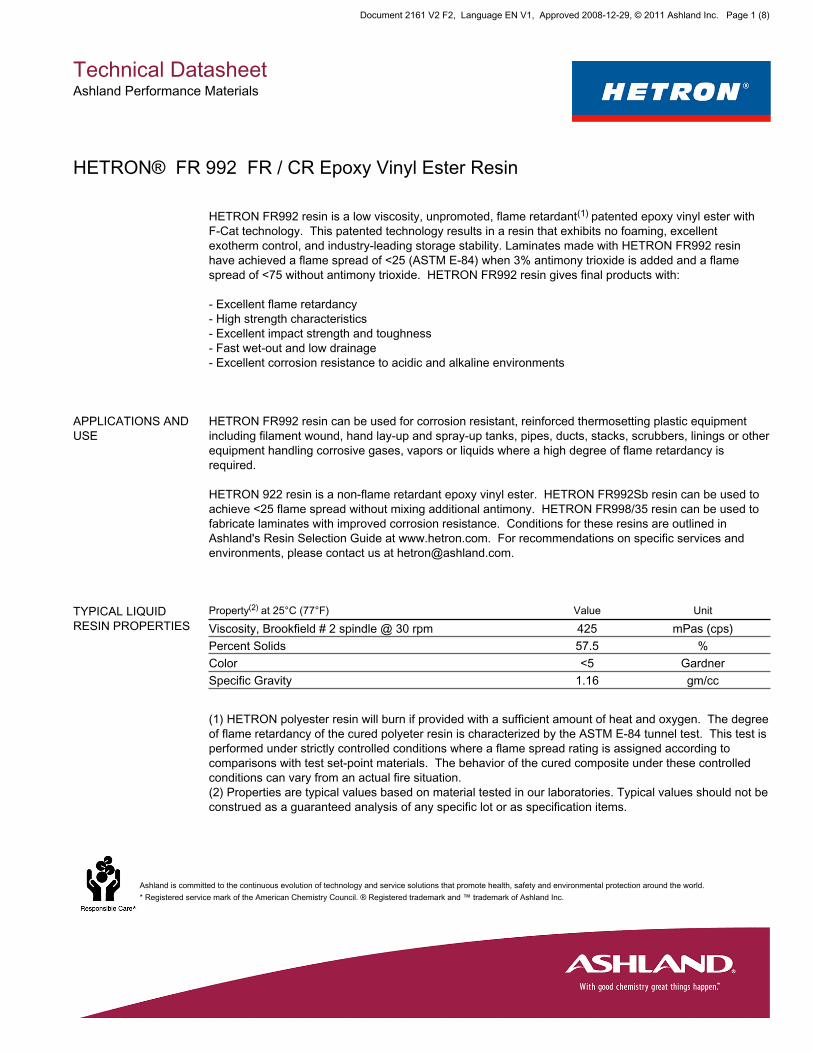
HETRON FR992 resin is a low viscosity, unpromoted, flame retardant(1) patented epoxy vinyl ester withF-Cat technology. This patented technology results in a resin that exhibits no foaming, excellentexotherm control, and industry-leading storage stability. Laminates made with HETRON FR992 resinhave achieved a flame spread of <25 (ASTM E-84) when 3% antimony trioxide is added and a flamespread of <75 without antimony trioxide. HETRON FR992 resin gives final products with:
- Excellent flame retardancy- High strength characteristics- Excellent impact strength and toughness- Fast wet-out and low drainage- Excellent corrosion resistance to acidic and alkaline environments
APPLICATIONS ANDUSE
HETRON FR992 resin can be used for corrosion resistant, reinforced thermosetting plastic equipmentincluding filament wound, hand lay-up and spray-up tanks, pipes, ducts, stacks, scrubbers, linings or otherequipment handling corrosive gases, vapors or liquids where a high degree of flame retardancy isrequired.
HETRON 922 resin is a non-flame retardant epoxy vinyl ester. HETRON FR992Sb resin can be used toachieve <25 flame spread without mixing additional antimony. HETRON FR998/35 resin can be used tofabricate laminates with improved corrosion resistance. Conditions for these resins are outlined inAshland's Resin Selection Guide at www.hetron.com. For recommendations on specific services andenvironments, please contact us at [email protected].
TYPICAL LIQUIDRESIN PROPERTIES
Property(2) at 25°C (77°F) Value UnitViscosity, Brookfield # 2 spindle @ 30 rpm 425 mPas (cps)Percent Solids 57.5 %Color <5 GardnerSpecific Gravity 1.16 gm/cc
(1) HETRON polyester resin will burn if provided with a sufficient amount of heat and oxygen. The degreeof flame retardancy of the cured polyeter resin is characterized by the ASTM E-84 tunnel test. This test isperformed under strictly controlled conditions where a flame spread rating is assigned according tocomparisons with test set-point materials. The behavior of the cured composite under these controlledconditions can vary from an actual fire situation.(2) Properties are typical values based on material tested in our laboratories. Typical values should not beconstrued as a guaranteed analysis of any specific lot or as specification items.
Technical DatasheetAshland Performance Materials
Ashland is committed to the continuous evolution of technology and service solutions that promote health, safety and environmental protection around the world.* Registered service mark of the American Chemistry Council. ® Registered trademark and ™ trademark of Ashland Inc.
Document 2161 V2 F2, Language EN V1, Approved 2008-12-29, © 2011 Ashland Inc. Page 1 (8)
HETRON® FR 992 FR / CR Epoxy Vinyl Ester Resin
TYPICAL CURINGCHARACTERISTICS
SPI Gel Time at 82°C (180°F) Bath Value UnitGel Time, 2% Luperco(2) ATC Paste 17 minutesTotal Time 23 minutesPeak Exotherm 193 (380) °C(°F)
MEKP Cure System Typical geltimes at different temperatures using different pre-acceleration systems and curing with Delta(3)
X-9, Lupersol(3) DDM-9 and Hi-Point(4) 90 catalysts(5).
CAUTION: Thoroughly mix promoters with resin before adding catalyst.
Temperature / Catalyst DMA Co-nap6% Delta X-9 DDM-9 HiPoint 90 HiPoint90/CHP50/50
18°C (65°F) / 1.25 phr 0.1 phr 0.2 phr 15minutes
27minutes
25minutes
60minutes
0.075 phr 0.2 phr 20minutes
30minutes
30minutes
70minutes
0.05 phr 0.2 phr 25minutes
40minutes
33minutes
75minutes
25°C (77°F) / 1.25 phr 0.04 phr 0.3 phr 10minutes
12minutes
13minutes
27minutes
0.04 phr 0.2 phr 15minutes
20minutes
20minutes
40minutes
0.04 phr 0.1 phr 30minutes
40minutes
36minutes
74minutes
29°C (85°F) / 1.25 phr 0.05 phr 0.3 phr 8 minutes 8 minutes 8 minutes 18minutes
0.05 phr 0.2 phr 10minutes
12minutes
12minutes
24minutes
Technical DatasheetAshland Performance Materials
Ashland is committed to the continuous evolution of technology and service solutions that promote health, safety and environmental protection around the world.* Registered service mark of the American Chemistry Council. ® Registered trademark and ™ trademark of Ashland Inc.
Document 2161 V2 F2, Language EN V1, Approved 2008-12-29, © 2011 Ashland Inc. Page 2 (8)
HETRON® FR 992 FR / CR Epoxy Vinyl Ester Resin
0.05 phr 0.1 phr 20minutes
25minutes
24minutes
50minutes
BPO / DMA CureSystem
Temperature / BPO Paste 50% DMA Gel Time18°C (65°F) / 2.0 phr 0.3 phr 26 minutes
0.2 phr 36 minutes0.1 phr 70 minutes
24°C (75°F) / 2.0 phr 0.3 phr 16 minutes0.2 phr 24 minutes0.1 phr 50 minutes
29°C (85°F) / 2.0 phr 0.3 phr 11 minutes0.2 phr 16 minutes0.1 phr 27 minutes
(3) Registered trademark of Atofina Chemicals Inc.(4) Registered trademark of Witco Chemical Corporation.(5) All levels are based on parts per hundred resin (phr)
Effect of CopperNaphthenate
Copper Naphthenate(6) (Cu-nap 8%) will influence gel time, gel-to-peak and peak exotherm at differenttemperatures and pre-accelerations. Catalyst used is Delta X-9 at 1.25 phr.
CAUTION: Thoroughly mix promoters with resin before adding catalyst.
Temperature / Cu-nap 8% Co-nap6% DMA Gel Time Gel-Peak Peak Exo18°C (65°F) / 0 phr 0.3 phr 0.05 phr 11 minutes 10 minutes 166°C
(330°F)18°C (65°F) / 0.04 phr 0.3 phr 0.05 phr 11 minutes 15 minutes 116°C
(240°F)
25°C (77°F) / 0 phr 0.1 phr 0.04 phr 26 minutes 12 minutes 168°C(335°F)
25°C (77°F) / 0.04 phr 0.1 phr 0.04 phr 22 minutes 17 minutes 129°C(265°F)
Technical DatasheetAshland Performance Materials
Ashland is committed to the continuous evolution of technology and service solutions that promote health, safety and environmental protection around the world.* Registered service mark of the American Chemistry Council. ® Registered trademark and ™ trademark of Ashland Inc.
Document 2161 V2 F2, Language EN V1, Approved 2008-12-29, © 2011 Ashland Inc. Page 3 (8)
HETRON® FR 992 FR / CR Epoxy Vinyl Ester Resin
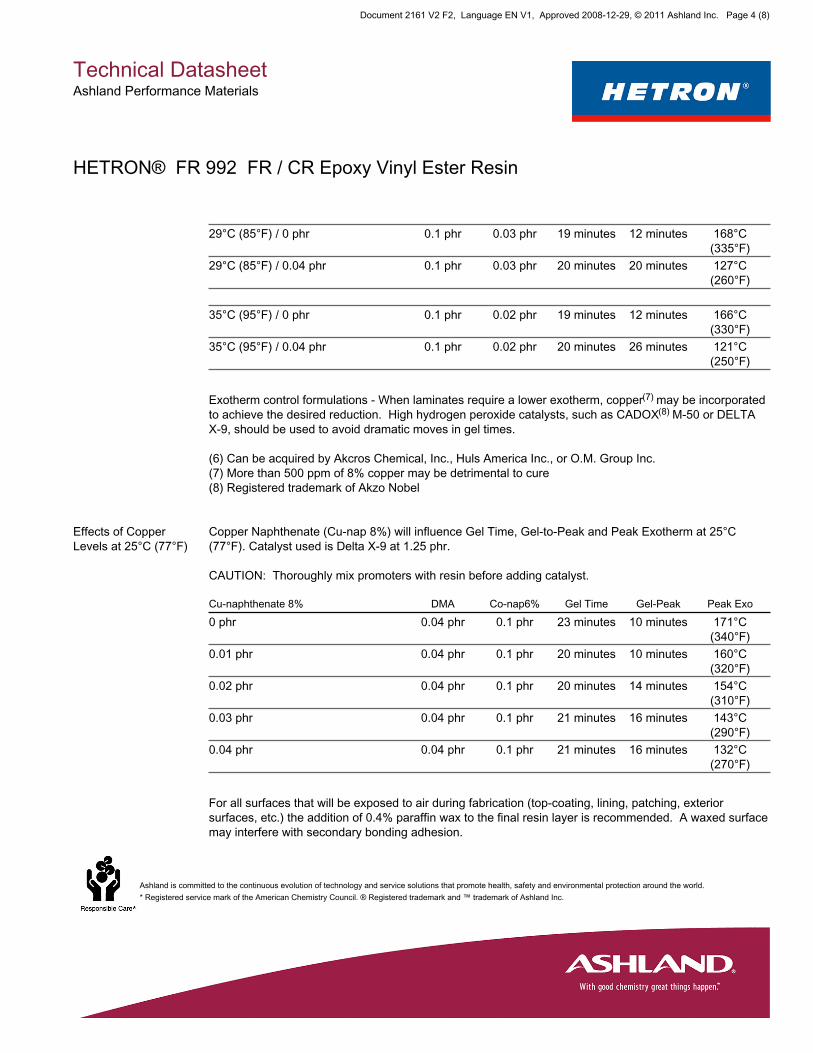
29°C (85°F) / 0 phr 0.1 phr 0.03 phr 19 minutes 12 minutes 168°C(335°F)
29°C (85°F) / 0.04 phr 0.1 phr 0.03 phr 20 minutes 20 minutes 127°C(260°F)
35°C (95°F) / 0 phr 0.1 phr 0.02 phr 19 minutes 12 minutes 166°C(330°F)
35°C (95°F) / 0.04 phr 0.1 phr 0.02 phr 20 minutes 26 minutes 121°C(250°F)
Exotherm control formulations - When laminates require a lower exotherm, copper(7) may be incorporatedto achieve the desired reduction. High hydrogen peroxide catalysts, such as CADOX(8) M-50 or DELTAX-9, should be used to avoid dramatic moves in gel times.
(6) Can be acquired by Akcros Chemical, Inc., Huls America Inc., or O.M. Group Inc.(7) More than 500 ppm of 8% copper may be detrimental to cure(8) Registered trademark of Akzo Nobel
Effects of CopperLevels at 25°C (77°F)
Copper Naphthenate (Cu-nap 8%) will influence Gel Time, Gel-to-Peak and Peak Exotherm at 25°C(77°F). Catalyst used is Delta X-9 at 1.25 phr.
CAUTION: Thoroughly mix promoters with resin before adding catalyst.
Cu-naphthenate 8% DMA Co-nap6% Gel Time Gel-Peak Peak Exo0 phr 0.04 phr 0.1 phr 23 minutes 10 minutes 171°C
(340°F)0.01 phr 0.04 phr 0.1 phr 20 minutes 10 minutes 160°C
(320°F)0.02 phr 0.04 phr 0.1 phr 20 minutes 14 minutes 154°C
(310°F)0.03 phr 0.04 phr 0.1 phr 21 minutes 16 minutes 143°C
(290°F)0.04 phr 0.04 phr 0.1 phr 21 minutes 16 minutes 132°C
(270°F)
For all surfaces that will be exposed to air during fabrication (top-coating, lining, patching, exteriorsurfaces, etc.) the addition of 0.4% paraffin wax to the final resin layer is recommended. A waxed surfacemay interfere with secondary bonding adhesion.
Technical DatasheetAshland Performance Materials
Ashland is committed to the continuous evolution of technology and service solutions that promote health, safety and environmental protection around the world.* Registered service mark of the American Chemistry Council. ® Registered trademark and ™ trademark of Ashland Inc.
Document 2161 V2 F2, Language EN V1, Approved 2008-12-29, © 2011 Ashland Inc. Page 4 (8)
HETRON® FR 992 FR / CR Epoxy Vinyl Ester Resin
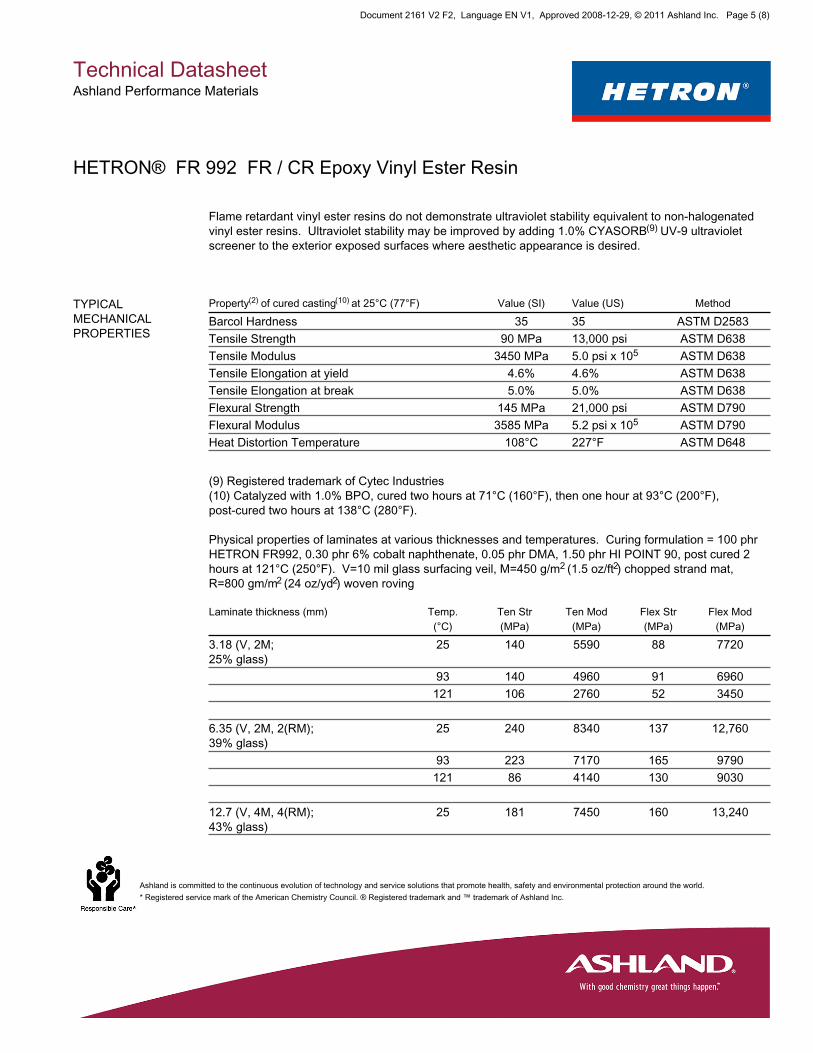
Flame retardant vinyl ester resins do not demonstrate ultraviolet stability equivalent to non-halogenatedvinyl ester resins. Ultraviolet stability may be improved by adding 1.0% CYASORB(9) UV-9 ultravioletscreener to the exterior exposed surfaces where aesthetic appearance is desired.
TYPICALMECHANICALPROPERTIES
Property(2) of cured casting(10) at 25°C (77°F) Value (SI) Value (US) MethodBarcol Hardness 35 35 ASTM D2583Tensile Strength 90 MPa 13,000 psi ASTM D638Tensile Modulus 3450 MPa 5.0 psi x 105 ASTM D638Tensile Elongation at yield 4.6% 4.6% ASTM D638Tensile Elongation at break 5.0% 5.0% ASTM D638Flexural Strength 145 MPa 21,000 psi ASTM D790Flexural Modulus 3585 MPa 5.2 psi x 105 ASTM D790Heat Distortion Temperature 108°C 227°F ASTM D648
(9) Registered trademark of Cytec Industries(10) Catalyzed with 1.0% BPO, cured two hours at 71°C (160°F), then one hour at 93°C (200°F),post-cured two hours at 138°C (280°F).
Physical properties of laminates at various thicknesses and temperatures. Curing formulation = 100 phrHETRON FR992, 0.30 phr 6% cobalt naphthenate, 0.05 phr DMA, 1.50 phr HI POINT 90, post cured 2hours at 121°C (250°F). V=10 mil glass surfacing veil, M=450 g/m2 (1.5 oz/ft2) chopped strand mat,R=800 gm/m2 (24 oz/yd2) woven roving
Laminate thickness (mm) Temp.(°C)
Ten Str(MPa)
Ten Mod(MPa)
Flex Str(MPa)
Flex Mod(MPa)
3.18 (V, 2M;25% glass)
25 140 5590 88 7720
93 140 4960 91 6960121 106 2760 52 3450
6.35 (V, 2M, 2(RM);39% glass)
25 240 8340 137 12,760
93 223 7170 165 9790121 86 4140 130 9030
12.7 (V, 4M, 4(RM);43% glass)
25 181 7450 160 13,240
Technical DatasheetAshland Performance Materials
Ashland is committed to the continuous evolution of technology and service solutions that promote health, safety and environmental protection around the world.* Registered service mark of the American Chemistry Council. ® Registered trademark and ™ trademark of Ashland Inc.
Document 2161 V2 F2, Language EN V1, Approved 2008-12-29, © 2011 Ashland Inc. Page 5 (8)
HETRON® FR 992 FR / CR Epoxy Vinyl Ester Resin

93 218 8340 150 15,580121 159 6760 131 6760
Laminate Thickness (in.) Temp.(°F)
Ten Str(psi)
Ten Mod(psix105 )
Flex Str(psi)
Flex Mod(psix105 )
0.125 (V, 2M;25% glass)
77 19.800 8.1 12,800 11.2
200 20,200 7.2 13,200 10.1250 15,400 4.0 7500 5.0
0.25 (V, 2M, 2(RM);39% glass)
77 35,000 12.1 19,900 18.5
200 32,400 10.4 23,900 14.2250 12,500 6.0 18,900 13.1
0.50 (V, 4M, 4(RM);43% glass)
77 26,200 10.8 23,200 19.2
200 31,600 12.1 21,400 22.6250 23,100 9.8 19,000 9.8
TYPICAL FLAMERETARDANCY OFLAMINATES
Tested Material Class ASTM E-84Flame Spread
HETRON FR992 resin laminate(11) with 3% antimonytrioxide
I <25
HETRON FR992 resin laminate(11) without antimonytrioxide
II <75
Cement Asbestos Board (control) I 0Red Oak (control) III 100
(11) Properties are typical values based on material tested in our laboratories. Typical values should notbe construed as a guaranteed analysis of any specific lot or as specification items. Laminate thickness =3.18 mm (0.125 in.) with approximately 27% glass content
Technical DatasheetAshland Performance Materials
Ashland is committed to the continuous evolution of technology and service solutions that promote health, safety and environmental protection around the world.* Registered service mark of the American Chemistry Council. ® Registered trademark and ™ trademark of Ashland Inc.
Document 2161 V2 F2, Language EN V1, Approved 2008-12-29, © 2011 Ashland Inc. Page 6 (8)
HETRON® FR 992 FR / CR Epoxy Vinyl Ester Resin
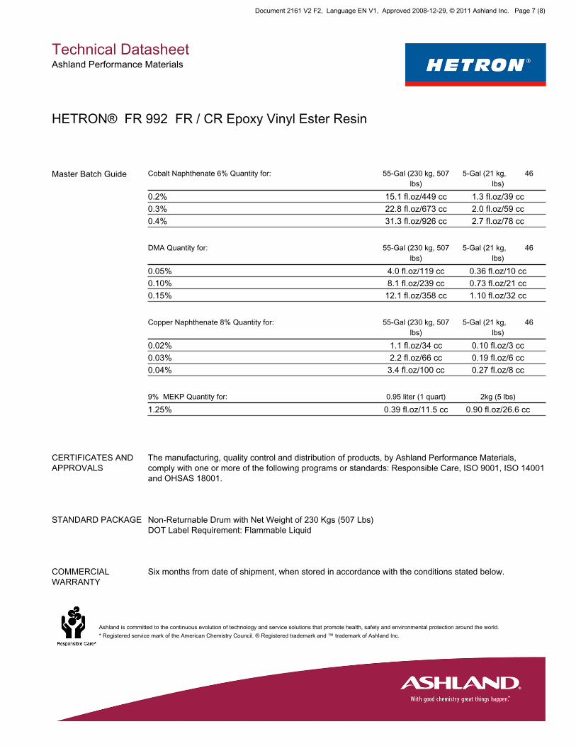
Master Batch Guide Cobalt Naphthenate 6% Quantity for: 55-Gal (230 kg, 507lbs)
5-Gal (21 kg, 46lbs)
0.2% 15.1 fl.oz/449 cc 1.3 fl.oz/39 cc0.3% 22.8 fl.oz/673 cc 2.0 fl.oz/59 cc0.4% 31.3 fl.oz/926 cc 2.7 fl.oz/78 cc
DMA Quantity for: 55-Gal (230 kg, 507lbs)
5-Gal (21 kg, 46lbs)
0.05% 4.0 fl.oz/119 cc 0.36 fl.oz/10 cc0.10% 8.1 fl.oz/239 cc 0.73 fl.oz/21 cc0.15% 12.1 fl.oz/358 cc 1.10 fl.oz/32 cc
Copper Naphthenate 8% Quantity for: 55-Gal (230 kg, 507lbs)
5-Gal (21 kg, 46lbs)
0.02% 1.1 fl.oz/34 cc 0.10 fl.oz/3 cc0.03% 2.2 fl.oz/66 cc 0.19 fl.oz/6 cc0.04% 3.4 fl.oz/100 cc 0.27 fl.oz/8 cc
9% MEKP Quantity for: 0.95 liter (1 quart) 2kg (5 lbs)1.25% 0.39 fl.oz/11.5 cc 0.90 fl.oz/26.6 cc
CERTIFICATES ANDAPPROVALS
The manufacturing, quality control and distribution of products, by Ashland Performance Materials,comply with one or more of the following programs or standards: Responsible Care, ISO 9001, ISO 14001and OHSAS 18001.
STANDARD PACKAGE Non-Returnable Drum with Net Weight of 230 Kgs (507 Lbs)DOT Label Requirement: Flammable Liquid
COMMERCIALWARRANTY
Six months from date of shipment, when stored in accordance with the conditions stated below.
Technical DatasheetAshland Performance Materials
Ashland is committed to the continuous evolution of technology and service solutions that promote health, safety and environmental protection around the world.* Registered service mark of the American Chemistry Council. ® Registered trademark and ™ trademark of Ashland Inc.
Document 2161 V2 F2, Language EN V1, Approved 2008-12-29, © 2011 Ashland Inc. Page 7 (8)
HETRON® FR 992 FR / CR Epoxy Vinyl Ester Resin
STORAGE Drums - Store at temperatures below 25°C (77°F). Storage life decreases with increasing storagetemperature. Avoid exposure to heat sources such as direct sunlight or steam pipes. To avoidcontamination of product with water, do not store outdoors. Keep containers sealed to prevent moisturepick-up and monomer loss. Mild mixing is recommended after prolonged storage. Rotate stock.
Bulk - See Ashland's Bulk Storage and Handling Manual for Polyesters and Vinyl Esters. A copy of thismay be obtained from Ashland Performance Materials at +1.614.790.3333 or 800.523.6963.
All other conditions being equal, higher storage temperatures will reduce product stability and lowerstorage temperatures will extend product stability.
Notice All information presented herein is believed to be accurate and reliable, and is solely for the user'sconsideration, investigation and verification. The information is not to be taken as an express or impliedrepresentation or warranty for which Ashland assumes legal responsibility. Any warranties, includingwarranties of merchantability or non-infringement of intellectual property rights of third parties, areherewith expressly excluded.
Since the user's product formulations, specific use applications and conditions of use are beyond thecontrol of Ashland, Ashland makes no warranty or representation regarding the results which may beobtained by the user. It shall be the responsibility of the user to determine the suitability of any of theproducts mentioned for the user's specific application.
Ashland requests that the user reads, understands and complies with the information contained hereinand the current Material Safety Data Sheet.
Technical DatasheetAshland Performance Materials
Ashland is committed to the continuous evolution of technology and service solutions that promote health, safety and environmental protection around the world.* Registered service mark of the American Chemistry Council. ® Registered trademark and ™ trademark of Ashland Inc.
Document 2161 V2 F2, Language EN V1, Approved 2008-12-29, © 2011 Ashland Inc. Page 8 (8)
HETRON® FR 992 FR / CR Epoxy Vinyl Ester Resin
f:\projects\2013\20132993 - exide vernon permitting assistance\sec files\reports\closure plan 11-2015\appendix g\appendix g 11 10 2015.docx
SCHEDULE (ATTACHMENT 3APPENDIX F X OF CLOSURE
IMPLEMENTATION PLAN)
f:\projects\2013\20132993 - exide vernon permitting assistance\sec files\reports\closure plan 11-2015\appendix g\appendix g 11 10 2015.docx
AIR MONITORING PLAN (ATTACHMENT 15APPENDIX H OF THE CLOSURE
IMPLEMENTATION PLAN)