engineering compendium part c equipment modules · pdf fileprocess control system pcs 7...
TRANSCRIPT

s
Process Control System PCS 7 Compendium Part C Equipment Modules Preliminary Draft V2.0
Preface Contents
Introduction 1 General 2 Components of equipment 3 Behavior of equipment modules 4
SIMATIC
Process Control System PCS 7 Engineering Compendium Part C Equipment Modules Manual
02/2008 Preliminary Draft V2.0
Siemens AG Automation and Drives PO Box 4848 90437 NUREMBERG GERMANY
Preliminary Draft V2.0 02/2008
Copyright © Siemens AG 2007 Modifications reserved
Safety instructions This manual contains instructions intended to ensure personal safety, as well as to protect equipment against damage. Instructions relating to your personal safety are indicated by a warning triangle, which does not appear with instructions solely relating to material damage. Warning notices appear as shown below, in descending order of hazard priority.
! Danger indicates that death or severe personal injury will result if proper precautions are not taken.
! Warning indicates that death or severe personal injury may result if proper precautions are not taken.
! Caution with a warning triangle indicates that minor personal injury may result if proper precautions are not taken.
Caution
without a warning triangle indicates that property damage may result if proper precautions are not taken.
Notice indicates that an unwanted result or state may occur if the relevant instruction is not observed.
If several hazard levels are applicable, the warning notice corresponding to the highest level is always used. If a warning notice with a warning triangle relates to the risk of personal injury, a warning relating to material damage may also be added to that same warning notice.
Qualified Personnel The equipment/system to which this documentation applies must always be set up and operated in accordance with this manual. Only qualified personnel should be allowed to commission and work on this equipment/system. Qualified personnel, as used in the safety-related information in this documentation, is defined as persons who are authorized to commission, to ground, and to tag equipment, systems and circuits in accordance with established safety practices and standards.
Correct Usage
Note the following:
! Warning The equipment may only be used for the applications described in the catalog and the technical description, and only in conjunction with equipment or components from other manufacturers which have been approved or recommended by Siemens. This product can only function correctly and safely if it is transported, stored, assembled, and installed correctly, and operated and maintained as recommended.
Trademarks All product names marked with the ® copyright symbol are trademarks of Siemens AG. Other product names in this document may be trademarks and third parties using these names for their own purposes may infringe upon the rights of the trademark owners.
Disclaimer of Liability We have checked the content of this manual for agreement with the hardware and software described. Since deviations cannot be precluded entirely, we cannot guarantee full agreement. The information in this manual is reviewed regularly and any necessary corrections will be included in subsequent editions.

Process Control System PCS 7 Compendium Part C Equipment Modules Preliminary Draft V2.0 iii
Preface
Subject of the manual This manual serves as a design guide, to be used in addition to the SIMATIC PCS 7 product documentation. Essential engineering steps are described in form of operation instructions to a large extent.
Based on practical experience, the suggested solution process is meant to cover general essential needs to avoid frequently occurring problems.
The compendium is divided into three parts:
• Part A Standard
• Part B Process Safety
• Part C Equipment Modules
Parts B and C are based as optional extras for standard part A.

Preface
Process Control System PCS 7 Compendium Part C Equipment Modules iv Preliminary Draft V2.0
Additional support If this manual does not contain the answers to any questions you may have about how to use the products described, please contact your local Siemens representative.
You can locate your contact at:
http://www.siemens.com/automation/partner
The guide that provides details of the technical documentation offered for the individual SIMATIC products and systems is available at:
http://www.siemens.de/simatic-tech-doku-portal
The online catalog and online ordering system are available at:
http://mall.automation.siemens.com/
Training Center We offer appropriate courses to help you to familiarize yourself with the SIMATIC S7 automation system. Contact your regional Training Center or the Central Training Center in Nuremberg, Germany. Phone: +49 (911) 895-3200. Internet: http://www.sitrain.com
Technical Support Technical support for all A&D products can be accessed • via the online Support Request form at
http://www.siemens.de/automation/support-request • Phone: + 49 180 5050 222 • Fax: + 49 180 5050 223 Additional information on our technical support is available on the Internet at http://www.siemens.de/automation/service
Service & Support on the Internet In addition to our documentation options, our expertise is also available to you online. http://www.siemens.com/automation/service&support Here you will be able to access: • The newsletter, which will keep you constantly up-to-date with the latest
information about our products • The right documents via our Service & Support search facility • A forum that provides users and specialists with an international platform for
sharing experiences • Your local Automation & Drives representative
Information about local service, repairs, spare parts The "Our service offer" section offers even more options.

Process Control System PCS 7 Compendium Part C Equipment Modules Preliminary Draft V2.0 v
Contents
Preface iii
Contents v
1 Introduction 1-1
2 General 2-1 2.1 What is an equipment module? ........................................................................ 2-1 2.1.1 Sepahration/Shared resources.........................................................................2-1 2.1.2 Reducing the number of different types............................................................2-2 2.1.3 Control strategies..............................................................................................2-2 2.1.4 Modes and states .............................................................................................2-2 2.1.5 Self-terminating and non-self-terminating.........................................................2-3 2.1.6 Type/instance model.........................................................................................2-3 2.2 Example of division in the P&I diagram............................................................ 2-4 2.3 Example of an EM type..................................................................................... 2-5 2.4 Performance specification, requirement specification, test log ........................ 2-5 2.5 Template for creating an SFC type................................................................... 2-6
3 Components of equipment modules 3-1 3.1 Control strategies.............................................................................................. 3-1 3.2 Setpoints ff ........................................................................................................ 3-1 3.3 Process values ................................................................................................. 3-2 3.4 Control values................................................................................................... 3-2 3.5 Parameters ....................................................................................................... 3-2 3.6 Bit memories..................................................................................................... 3-2 3.7 Times ................................................................................................................ 3-2 3.8 Note texts.......................................................................................................... 3-2 3.9 Block contacts................................................................................................... 3-3 3.10 Position texts .................................................................................................... 3-3 3.11 Messages ......................................................................................................... 3-3 3.12 Sequencing logic .............................................................................................. 3-3
4 Behavior of equipment modules 4-1 4.1 State logic ......................................................................................................... 4-1 4.1.1 Starting/Run division.........................................................................................4-2 4.1.2 Completing/Completed .....................................................................................4-3 4.1.3 Holding/Held/Resuming....................................................................................4-3 4.1.4 Error/Held (error)/Resuming (error) ..................................................................4-3 4.1.5 Differences between the hold and error branches ...........................................4-4 4.1.6 Aborting/Stopping .............................................................................................4-4 4.1.7 State change.....................................................................................................4-5 4.1.8 Closing and resumption lockouts......................................................................4-5 4.2 Setpoint changes during operation................................................................... 4-6 4.3 Transmitting messages..................................................................................... 4-7 4.4 Using times ....................................................................................................... 4-8

Contents
Process Control System PCS 7 Compendium Part C Equipment Modules vi Preliminary Draft V2.0
4.4.1 Calculating the elapsed time ..........................................................................4-13 4.4.2 Times in Hold..................................................................................................4-14 4.5 Active control strategy change ....................................................................... 4-15 4.6 Multiplexing CMs ............................................................................................ 4-16 4.7 CMs in Auto/Manual ....................................................................................... 4-16 4.8 Optional CMs .................................................................................................. 4-18 4.9 Non-retentive/retentive sequencers................................................................ 4-18 4.10 Setting posi texts ............................................................................................ 4-19 4.11 Self-terminating vs. non-self-terminating equipment modules ....................... 4-20 4.12 Returns when resuming.................................................................................. 4-22 4.13 Changing the faceplate................................................................................... 4-25 4.13.1 CM list .............................................................................................................4-25 4.13.2 Additional buttons in the SFC type faceplate..................................................4-26 4.14 Calculations .................................................................................................... 4-27 4.15 Combining sequencers ................................................................................... 4-28 4.16 Naming............................................................................................................ 4-30 4.17 Start conditions for sequencers ...................................................................... 4-33 4.18 Tips and tricks................................................................................................. 4-34 4.18.1 Editing within the project.................................................................................4-34 4.18.2 Block size of an SFC type...............................................................................4-34 4.18.3 SFC type following AS stop/restart.................................................................4-35 4.18.4 Final step ........................................................................................................4-35 4.18.5 EPH/EOP........................................................................................................4-36 4.18.6 Presetting control strategies ...........................................................................4-37 4.18.7 Instance-specific deselection/selection of control strategies..........................4-37 4.18.8 Connecting to BATCH ....................................................................................4-38 4.18.9 Multiple instances of a type in a unit...............................................................4-38 4.18.10 Closing lockout, start disable for SIMATIC BATCH........................................4-39 4.18.11 Start disable/resumption lockout for SIMATIC BATCH for equipment phases
previously started manually ............................................................................4-39 4.18.12 Continuous function ........................................................................................4-40

Process Control System PCS 7 Compendium Part C Equipment Modules Preliminary Draft V2.0 1-1
1 Introduction
About this topic Hierarchical software structures are usually created during the automation of batch processes. These structures are described in several standards (see NAMUR NE33, ISA S88.01).
Both higher-level recipe control and the group control level have an important role to play when it comes to such structures, with the latter being of particular significance in terms of engineering work. The software blocks used here are known internationally (S88) as equipment modules (EM) and equipment phases (EPH), whilst in German-speaking countries (NAMUR) they are known as Technische Einrichtungen and Technische Funktionen.
Content of this document This document describes how equipment modules/phases can be implemented using SIMATIC PCS 7 V7.0 with the help of SFC types.
The SFC editor is a tool found in SIMATIC PCS 7 and used to create sequential control systems. This manual is a supplement to the SFC manual for S7 and provides additional information as regards the configuration of EMs and their properties.
Master recipe control
Equipment Module
Interface for recipe control
Block contacts
EquipmentPhase
CM CM
Single control level
Group control level
Batch package
Valve control block
Motor control block
Dosing, heating/cooling, stirring
SIMATIC BATCH
CM

Introduction
Process Control System PCS 7 Compendium Part C Equipment Modules 1-2 Preliminary Draft V2.0
Various procedures are described at certain points throughout the documentation, although they are not exhaustive. Sometimes a preferred procedure will be described; in other cases, the selection will depend on various supplementary conditions, such as the application case, history, customer philosophy, minimization of implementation work, minimization of system load, etc.
A consistent method should be selected for and observed throughout a project.
For an introduction to the wider context of the structure and automation of batch processes, we recommend the DVD “SIMATIC BATCH – An Introduction” (MLFB E20001-W180-P280-X-7400), which is provided as part of the PCS 7 Video Suite.
Definition of terms Internationally recognized terms are mainly used in this documentation. How these terms relate to German terms previously used and their sources (standards) are shown in the table below:
Term used in this document
German (source)
English (source)
unit Teilanlage (NE33) unit (NE33 English version and S88.01)
equipment module (EM) in the physical model (plant model)
Technische Einrichtung (NE33), Grundfunktionsbaustein (GF)
equipment module (EM) (NE33 English version and S88.01)
equipment phase (EPH) in the procedural model (recipe hierarchy)
Techn. Einrichtung, Technische Funktion (NE33)
equipment phase (EPH) (S88.01)
setpoint (SP) Sollwert (= guide parameter) (in general use)
setpoint (in general use)
process value (PV) Istwert (= feedback parameter) (in general use)
actual value, process value (in general use)
mode Betriebsart (in general use)
(operation) mode (S88.01)
state Betriebszustand (in general use)
(operation) state (S88.01)
control module (CM) unterlagerter Einzelsteuerungsbaustein (in general use) Grundfunktionselement (GFE)
control module (CM) (S88.01)
EPH Technische Einrichtung, Technische Funktion (NE33)
equipment phase (EPH) (S88.01)
control module Meßstelle control module P&I (piping and instrumentation) diagram
Rohrleitung & Instrumentierung Schema

Process Control System PCS 7 Compendium Part C Equipment Modules Preliminary Draft V2.0 2-1
2 General
This chapter describes the general structure of an equipment module/phase (EPH), along with examples.
2.1 What is an equipment module?
An equipment module is a closed process-engineering unit; it is used to implement a task definition on the group control level and, thus, a process-engineering (sub-)task. There is unlimited freedom in how you define the scope of equipment modules and the types derived from them; if you are clever in your choices, you may find types which can be used outside of the specific unit class, or even the specific plant, in question. On the other hand, specific process engineering features are indeed reflected in the EM design, so that it is rarely possible to create general libraries which are not application-specific, unlike on a control module.
2.1.1 Sepahration/Shared resources
To make it easier to locate the EM for a given plant structure, it makes sense to group together all the control modules that are involved in the same process-engineering function in the P&I diagram so that there are different groups for different functions (example: heating/cooling system, dosing devices, template, ventilation system).
The separation between EMs (as components of a unit) and standalone units is not always obvious, as the example of a reservoir shows. The following rule may help here:
“A unit cannot contain more than one batch at a time."
If the process operation is configured such that the next batch will be started in the reservoir while the previous batch is still being processed in the main unit, the reservoir must be modeled as a separate unit.
The aim of separating the EM is to assign precisely one EM to each control module. However, in some cases it may be necessary for two different EMs to share the use of one control module (CM)
(“shared resources”). This is not a problem for read-only access, but if final controlling elements are to be activated, the resolution of possible conflicts must be considered (S88: “arbitration”). See also Chapter 8.4.8 Multiplexing CMs.
Shared resources of this type should be avoided as far as possible (although, in practice, this is not feasible in all cases), as they generate additional planning and engineering work and bring with them the risk of usage conflicts during production.

General
Process Control System PCS 7 Compendium Part C Equipment Modules 2-2 Preliminary Draft V2.0
2.1.2 Reducing the number of different types
Reusability should be taken into account when defining the EM, so the number of different EM types can be kept as small as possible (reducing engineering work and AS resources). This relates to both the sequencing logic and the use of the same instrumentation, as far as possible. If this is not provided by the actual plant equipment, you should work with “Optional CMs” here, i.e. with CMs which may be available in the EM, but which do not have to be (see Chapter 4.8 „Optional CMs“).
2.1.3 Control strategies
It is often the case that various process-engineering sequences can be implemented using the unit instrumentation belonging to one EM. For example, acid dosing can both provide a certain amount of substance as well as set a pH value. These alternative EM operating methods are called “control strategies”, which have different sequences and also, often, different sets of setpoint parameters.
In selecting the control strategy, different sequencers or alternative branches of a run sequencer can be activated, along with the associated setpoint sets. The sequencer is activated via the start conditions of the step sequencer with the block contacts of the control strategy. (QCS � Control Strategy)
Control strategies and their associated step sequencers can be selected/deselected on an instance-specific basis using the available equipment property during implementation.
The EM is usually disabled for a time, i.e. it returns to its initial state, in order to change from one control strategy to another. However, application requirements may mean that it is necessary to implement an “active control strategy change” (previously known as an “on-the-fly control strategy change”), i.e. to activate a new control strategy directly from the one that is currently active (see Chapter 4.5 „Active control strategy change“); this prevents motors being temporarily disabled, for example.
2.1.4 Modes and states
An EM has different states (e.g. Starting, Run, Holding, etc.), which are defined in an operating state logic, and different modes (Manual, Automatic). Any states or transitions can be defined in the SFC editor; they must, however, be coordinated with higher-level recipe control.

General
Process Control System PCS 7 Compendium Part C Equipment Modules Preliminary Draft V2.0 2-3
2.1.5 Self-terminating and non-self-terminating
There are two basic ways of terminating an EPH: self-terminating EPH and non-self-terminating EPH.
In the former case, the EPH algorithm automatically detects that the process-engineering target has been reached and sets the “Completed” state; the higher-level control then detects this state, resets the EPH to its initial state, and starts to check the subsequent step enabling conditions. A typical example of this is a dosing procedure.
In the latter case, the EPH algorithm runs until an interim target is reached and sets the “Ready to be terminated” state; the phase is usually still active in this state. The higher-level control (e.g. SIMATIC BATCH) detects this state and starts to check the subsequent step enabling conditions in the control recipe. If these conditions are met, a second handshake is performed with the EPH, whereby the EPH is disabled and set to its initial state; the higher-level control then activates the next recipe step.
A typical example of a non-self-terminating EPH is a mixing procedure which is to be terminated by an external event (e.g. the end of a dosing procedure running simultaneously); the active interim state would be achieved when the target mixing speed was reached ("Ready to be terminated") and the finished dosing procedure would then disable the mixer.
SIMATIC BATCH supports both types of termination; the EPH algorithm can control this by setting the corresponding states.
2.1.6 Type/instance model
The type/instance model comes into effect when SFC types are used. This means:
• The block structure (list of input and output parameters incl. default values) and the sequencing logic are defined in the type; the sequencing logic can only access the block inputs and outputs.
• The input parameters can then be reparameterized or interconnected, instance-specific high and low limits can be defined, etc. at the instance.
• Control strategies can be selected/deselected using the available equipment property at the instance.
• Subsequent type changes can be made at a central location and then automatically passed on to the instances.
The type/instance model brings with it significant benefits when it comes to configuring, qualifying, servicing, and maintaining the plant. However, it requires every value to be read or written to be managed via the block inputs/outputs.

General
Process Control System PCS 7 Compendium Part C Equipment Modules 2-4 Preliminary Draft V2.0
2.2 Example of division in the P&I diagram
The excerpt from a P&I diagram below is designed to clarify how CMs are grouped together to form an equipment phase.
The CMs surrounded by a border belong to one EM, as they fulfill a shared process-engineering task.
Tank1
Tank2
Tank3KW Dampf
AbluftN2
V11
GO11
PI11
GO21
PICA21
SIC11
UC33
FOIC33
UC32
FOIC32
UC31
FOIC31
GO31
PI22 M
V21 V31

General
Process Control System PCS 7 Compendium Part C Equipment Modules Preliminary Draft V2.0 2-5
2.3 Example of an EM type
Here is an example of a “temperature adjustment” EM type, by way of introduction and to promote better understanding.
2.4 Performance specification, requirement specification, test log
Here you will find a sample performance specification, requirement specification, and test log for two equipment phases/modules for the functions "temperature" and "discharge".
Discharge
Requirement specification Functional specification Test procedure
Req_Spec_Discharge_V1.0.doc
Func_Spec_Discharge_V1.0.doc
Test_Spec_Discharge_V1.0.doc
Temperature
Requirement specification Functional specification Test log procedure
Req_Spec_Temperature_V1.0.doc
Func_Spec_Temperature_V1.0.doc
Test_Spec_Temperature_V1.0.doc
The additional documents will be available in the Service and Support portal interlinked soon.

General
Process Control System PCS 7 Compendium Part C Equipment Modules 2-6 Preliminary Draft V2.0
2.5 Template for creating an SFC type
Here you will find a template (creation tool) for implementing an equipment phase.
Once completed, the template (preparation) is intended to make it easier for you to implement the equipment phase by means of SFC types in the SIMATIC Manager. The template (instantiation) is intended to make it easier for you to instantiate the SFC type.
Template for SFC type and instance
SFC TYPE creation Instantiation
SFC_Typ_Arbeitsvorlage_V1_0.doc
SFC_Instanzierung_Arbeitsvorlage.xls
The additional documents will be available in the Service and Support portal interlinked soon.

Process Control System PCS 7 Compendium Part C Equipment Modules Preliminary Draft V2.0 3-1
3 Components of equipment modules
Information on components is required to implement an EM and must be specified at the start of EM configuration. This information is needed in order to write a requirement specification. These components are significant in terms of behavior (e.g. control strategy) on the one hand, and for the type interface (e.g. setpoints, CMs) on the other.
The meanings of these components are described in the SFC Online Help (characteristics) and are reconsidered here only from the point of view of an equipment module.
3.1 Control strategies
Different sequences within an equipment phase can be defined by means of control strategies. The control strategies capture the active aspects of phases, i.e. those aspects which involve the plant unit actively doing something. This is stored in step sequencers.
The sequencer is activated via the start conditions of the step sequencer with the block contact (QCS) of the control strategy.
An EPH’s initial state is defined as the idle state.
The control strategies of an equipment phase are batch-relevant and are available to the higher-level control (e.g. SIMATIC BATCH) for creating recipes.
3.2 Setpoints ff
Setpoints can be used to influence the behavior of the control strategies and the control of the SFC type. They can be specified by means of operator input or via a higher-level control (e.g. SIMATIC BATCH). Setpoints can be assigned to individual control strategies.
When a setpoint is defined, an input is automatically created for the associated actual value. Setpoints of an SFC type generally contain block contacts for process and control values.
Setpoints of an EM are batch-relevant and are called parameters on the higher-level control (e.g. SIMATIC BATCH) - not to be confused with the parameters of the SFC type.
Special features of setpoints are the available data types “PI” and “PO”, which essentially represent a REAL setpoint but are supplemented by the additional attributes “Material” and “Tracking ID” (required for material tracking via SIMATIC BATCH to SIMATIC IT).

Components of equipment modules
Process Control System PCS 7 Compendium Part C Equipment Modules 3-2 Preliminary Draft V2.0
The DEST, SOURCE, VIA, and TKEY data types are also available and you can assign enumerations to them (required for Route Control and SIMATIC IT).
3.3 Process values
Process values are used to connect process signals (e.g. level) to the phase and serve to control the SFC type. As only the actual value is reported to the phase and the equipment module does not have to be activated here, the individual signals can be connected to several equipment phases in order for them to be used in the sequencing logic.
Process values are primarily used for step enabling conditions in step sequencers.
3.4 Control values
Control values are used to control blocks which are not connected to the phase via the CM interface. This can be used, for example, to separate a cascade controller.
3.5 Parameters
Parameters are used to modify the behavior of the SFC type on an instance-specific basis (e.g. limit values, options).
3.6 Bit memories
Bit memories serve as a clipboard for values. They are created as static variables, which are not visible on the interface display in CFC.
3.7 Times
In implementing EMs, times are often needed, such as a monitoring time or mixer run time. These times can be implemented using a default time block (TIMER_P), which supports different modes (Pulse, Extended pulse, ON delay, Latching ON delay, OFF delay) with the advantage that they are incremented by the operating system. When the SFC type is used, this time block is automatically embedded for editing times.
3.8 Note texts
Note texts are used for displaying additional notes on the operator station (OS). They can also be used to display additional information in parallel with a message in the event of an error. However, this must be provided for in the configuration.
The texts, which are predefined in the characteristics dialog, can be displayed simply by setting an output (OPTIPNO) on the interface. This can be acknowledged

Components of equipment modules
Process Control System PCS 7 Compendium Part C Equipment Modules Preliminary Draft V2.0 3-3
by the operator. There are various standard note texts, which are triggered, for example, in the event of a setpoint check (e.g. "Low limit undershot”). A note text is not connected to the message system and is used for operator prompting (prerequisite: must be integrated in the message system via the configuration as operator prompting, for example, otherwise the text will only be visible as additional information).
3.9 Block contacts
Block contacts are blocks on the control module. The control module (CM) is activated by the EM. As well as block activation, feedback on the relevant state is also required. These activations and feedbacks are connected to the EM via interface elements.
A cohesive group of interface elements is called a block contact.
In order to be able to use block contacts to connect basic control blocks, at block type level you must specify the relevant I/Os for creating a link to an SFC type.
This is achieved by assigning the “S7_contact = true” system attribute to the block I/O. The technological blocks from the PCS 7 Library have already been prepared accordingly. If required, you can make project-specific modifications to the block types supplied in terms of the relevant I/Os.-{}-
3.10 Position texts
Position texts (posis) are used for displaying the current sequence state on the OS. These texts can be set in the sequential control system and displayed in the EPH faceplate. Furthermore, a posi can be used in a higher-level control to query an interim state, for example. An example is the querying of rough/fine dosing.
3.11 Messages
Equipment phases also transmit messages, which can be set or reset from within the sequence. To do this, the message class and message class must be defined. An example of a message could be a valve fault message or an operator prompt.
3.12 Sequencing logic
The process-engineering task itself is implemented in the sequencing logic. The behavior in each individual EM state must be defined for the initial state and for every control strategy.


Process Control System PCS 7 Compendium Part C Equipment Modules Preliminary Draft V2.0 4-1
4 Behavior of equipment modules
This chapter describes the individual task definitions/behaviors of an EM, along with possible solutions.
The solutions refer to creation using the SFC type.
4.1 State logic
The state logic used here is that of the SFC type, which has 16 different states. A sequencer can be stored in the transient states (Starting [2], Completing [4], Aborting [13], etc.), but this is not essential.

Behavior of equipment modules
Process Control System PCS 7 Compendium Part C Equipment Modules 4-2 Preliminary Draft V2.0
4.1.1 Starting/Run division
The normal sequence of events is determined by the following states, if no errors occur:
From Starting [2] to Run [3].
Starting
STARTING
Completing
Starting
Ready
Ended
Active
1
2
3
6
4
SELFCOMP=1
Reset
A sequencer can be configured in each of the Starting [2] and Run [3] states. A Starting [2] step sequencer is advantageous if several control strategies are used, where the same basic settings are made prior to the Run [3] step sequencer. If a step sequencer is stored, Starting remains on the block for as long as this step sequencer is being processed.
There are two different philosophies when it comes to dividing sequence steps into the Starting [2] and Run states in terms of functions:
• The Starting state can be used as the state in which switch-on is actually to take place (e.g. mixer on). The final control elements then really are active in the Run state.
• The Starting state can be used for preparation purposes (reset bit memories, etc.) and the actual EM sequencing logic becomes active (and, therefore, the final control elements are switched on, for example) in the Run state.

Behavior of equipment modules
Process Control System PCS 7 Compendium Part C Equipment Modules Preliminary Draft V2.0 4-3
As a rule, any errors (Held [8] or Held (error) [11]) must be carefully considered: A return from the Resuming state leads directly to the Run state. If a lot of data is saved in the Starting state, therefore, this may also have to be carried out in Resuming.
• A start condition for the sequencer Starting [2]: STARTING = (Starting) (TRUE)
• A start condition for the sequencer Run [3]: RUN = (Run) (TRUE)
4.1.2 Completing/Completed
In Completing [4] the EM is disabled and switched to the safe state in accordance with the stored sequence. In many cases, these are the same sequences as for Aborting [13] or Stopping [15]. If this is indeed the case, the Completing [4] sequencer can also be used for Aborting [13] or Stopping [15].
• A start condition for the sequencer Completing [4]: COMPLETING = Completing (TRUE)
In the Completed [6] state the EM is already switched off and simply waiting to be reset. The reset function can be set using a parameter (SELFRESET) in such a way that it will be performed automatically (without operator input) in Manual. In Automatic, this is carried out by the higher-level recipe control.
4.1.3 Holding/Held/Resuming
In Holding [7] the normal sequence is held and switched to the safe state in accordance with the stored sequence. This can also consist of a targeted shutdown in several stages.
• A start condition for the sequencer Holding [7]: HOLDING = Holding (TRUE)
In Resuming [9] the EM currently in the Held [8] state is restarted. There are various positions at which the active sequencer may restart (see Chapter 4.12 ”Returns when resuming”).
4.1.4 Error/Held (error)/Resuming (error)
In the Error [10] state the lower-level blocks are switched to a safe state. This can also consist of a targeted shutdown in several stages.
• A start condition for the sequencer Error [10]: ERROR = Error (TRUE)
In Resuming [12] the EM currently in the Held [11] state is restarted. There are various positions at which the active sequencer may restart (see Chapter 4.12 “Returns when resuming”).

Behavior of equipment modules
Process Control System PCS 7 Compendium Part C Equipment Modules 4-4 Preliminary Draft V2.0
4.1.5 Differences between the hold and error branches
The hold branch is intended for scheduled/desired holding procedures. This branch can also be accessed via a condition. The error branch is intended for an “undesired” error case and cannot be activated manually (except for test purposes).
It is frequently the case that the same thing is implemented in both branches.
4.1.6 Aborting/Stopping
Aborting
From all states (except Ready,
Aborting, Aborted)
Stopping
From all states (except Ready,
Aborting, Aborted,Stopping, Stopped)
13 15
14 16
ResetCancel Stop
Aborted Stopped
As with Error/Hold, there is also the question of how to differentiate between these states:
In Stopping [15] the EM is subject to a controlled shutdown, similar to with Completing [4] (e.g. the product is transported out of the screw conveyor). In the Aborting [13] branch everything is disabled immediately, without observing an order or any feedback (screw conveyor off immediately). For the most part, however, the same sequence is implemented in Aborting [13] and Stopping [15].
• A start condition for the sequencer Aborting [13]: ABORTING = Aborting (TRUE)
• A start condition for the sequencer Stopping [15]: STOPPING = Stopping (TRUE)
The Cancel command has a higher priority. The Aborting [13] state can be reached from Stopping [15], although not vice versa.

Behavior of equipment modules
Process Control System PCS 7 Compendium Part C Equipment Modules Preliminary Draft V2.0 4-5
4.1.7 State change
An SFC-type state change (step sequencer change) can be achieved in one of four ways:
• In Manual, by means of a manual operation (e.g. via SFC type faceplate)
• In Automatic, by means of the automatic interface
• Via LOCK inputs for interconnections (e.g. LOCKERROR)
• Via INT inputs (e.g. INTHOLD) for a state change from the sequencer
It is clear, therefore, how easy it is to use INT elements in the sequencer. The element is also easy to set. The SFC-type state logic evaluates and immediately resets the IN-OUT parameter. The change will take place if it is permitted within the state diagram. If the command cannot be executed, it will be rejected.
An example of using an INT command is the transition to the Error state (INTERROR) as a function of a condition.
4.1.8 Closing and resumption lockouts
The closing lockout can be used to prevent an EPH from starting. You should note that this is realized via an input on the instance. The closing and resumption lockouts are, therefore, instance-specific.
The closing lockout is interconnected via the default input ENSTART (for starting from the initial state) or ENASTART (for starting from the Run state – see 4.5 „Active control strategy change“). The interlock is implemented by means of a series-connected interlock block. The ENRESUME input is used for the resumption lockout.

Behavior of equipment modules
Process Control System PCS 7 Compendium Part C Equipment Modules 4-6 Preliminary Draft V2.0
4.2 Setpoint changes during operation
If a setpoint needs to be changed during operation, some points must be considered:
First, it is important to take this into account in the sequential control system of the EM. It may be the case that a return must be performed within the sequence when a setpoint is changed, or that the setpoint must be assigned in each relevant step (e.g. when forwarding to a CM).
Furthermore, the setpoint can only be changed in the EM when that EM is in Manual. In Automatic the EM blocks setpoint operation. In this case, the change must be made by the higher-level recipe control (SIMATIC BATCH).
If a setpoint change is required in the active state, it must be enabled on the EM block for every setpoint. This is achieved via input “sp_ENOP” (sp = I/O name of the setpoint). If this input is set, the setpoint can be changed. The input can also be set or reset in the sequencing logic.
The setpoint change must also be activated in the faceplate (picture @pg_@sfc_type_actualsp.PDL):
If no setpoint change is required during operation, this can usually be deactivated for all SFC types here too.

Behavior of equipment modules
Process Control System PCS 7 Compendium Part C Equipment Modules Preliminary Draft V2.0 4-7
4.3 Transmitting messages
Messages are transmitted in an EM via the inputs SIG_x or NSIG_x for an SFC type.
These elements must be reset by the block too, if the situation which triggered the message has been remedied.

Behavior of equipment modules
Process Control System PCS 7 Compendium Part C Equipment Modules 4-8 Preliminary Draft V2.0
An SFC type contains one Alarm 8P and two Notify_8 blocks, although some messages are assigned by default.
The messages are directly connected to the SIG_X and NSIG_X inputs. Input NSIG_12 is the fourth message in the second Notify_8 block (SIG4).
I/O name Message ID Message block
SIG_2 SIG2 Alarm 8P SIG_3 SIG3 Alarm 8P SIG_4 SIG4 Alarm 8P SIG_5 SIG5 Alarm 8P SIG_6 SIG6 Alarm 8P SIG_7 SIG7 Alarm 8P SIG_8 SIG8 Alarm 8P NSIG_12 SIG4 2. Notify 8 NSIG_13 SIG5 2. Notify 8 NSIG_14 SIG6 2. Notify 8 NSIG_15 SIG7 2. Notify 8 NSIG_16 SIG8 2. Notify 8
4.4 Using times
Times are often used in an EM. The SFC type allows these times to be defined in the characteristics dialog. A TIMER_P block is used for each time. The interface elements of this block are added to the interface of the SFC type.
The time counter’s mode can be set via input xx_MODE.

Behavior of equipment modules
Process Control System PCS 7 Compendium Part C Equipment Modules Preliminary Draft V2.0 4-9
This should be reset prior to using a time by setting input xx_RESET and resetting the input for starting the time (xx_I0).

Behavior of equipment modules
Process Control System PCS 7 Compendium Part C Equipment Modules 4-10 Preliminary Draft V2.0
It is also possible to load the time in advance (xx_TIME0).
If the setpoint is defined in minutes, please note that the time must be calculated in seconds, as the SFC type requires a time in seconds. The MUL_R block is available for calculating times. The time setpoint (e.g. SP_mixing_time_Q) is interconnected with input IN1 of the MUL_R block. A process value (e.g. PV_mixing_time) containing the time in seconds is also defined on the EM and interconnected with output OUT of the MUL_R block.

Behavior of equipment modules
Process Control System PCS 7 Compendium Part C Equipment Modules Preliminary Draft V2.0 4-11
Once the time has been reset, the sequencer can continue.
The reset command on the Termination tab is also reset during the reset process.

Behavior of equipment modules
Process Control System PCS 7 Compendium Part C Equipment Modules 4-12 Preliminary Draft V2.0
If the time is to be started now, the input pulse of the time counter (xx_I0) can be set.
You query whether the time has elapsed via the output pulse (xx_Q0).

Behavior of equipment modules
Process Control System PCS 7 Compendium Part C Equipment Modules Preliminary Draft V2.0 4-13
4.4.1 Calculating the elapsed time
In the example, the time that has elapsed thus far is also to be displayed as an actual value. The elapsed time is now calculated in minutes using a SUB_R and a DIV_R block. The output of the DIV_R block is interconnected with actual value SP_mixing_time_AI.

Behavior of equipment modules
Process Control System PCS 7 Compendium Part C Equipment Modules 4-14 Preliminary Draft V2.0
4.4.2 Times in Hold
If a time, as described above, is used, it continues to run if the EM switches to the Holding state. However, it could be that this is not desired, in which case the time must be temporarily stored.
A bit memory must be defined in the characteristics dialog (e.g. saved time (I/O name: FL_time)) for the purpose of temporary storage.
The time currently remaining is assigned to this bit memory (xx_PTIME). The input pulse of the time counter (xx_I0) also has to be reset.
The remaining time can then be set again in the Resuming state.

Behavior of equipment modules
Process Control System PCS 7 Compendium Part C Equipment Modules Preliminary Draft V2.0 4-15
4.5 Active control strategy change
“Active control strategy change” means that a control strategy can be started while another one is running.
This function is needed for many EMs and can be activated/deactivated on the SFC type via input ENASTART (enable active start). If this input is set, an active control strategy can be interrupted when another is started. The same control strategy can also be restarted.
In many cases, the start conditions for active control strategy change are the same as for starting from the initial state, but they can be supplemented by additional conditions. A condition could be, for example, that the other control strategy may only be switched to once a particular step in the sequencer has been performed. The control strategies to be started may also be restricted by means of external logic.

Behavior of equipment modules
Process Control System PCS 7 Compendium Part C Equipment Modules 4-16 Preliminary Draft V2.0
4.6 Multiplexing CMs
In an ideal world it should be avoided, but sometimes there's no getting around it: activating a CM by means of multiple equipment phases/modules.
In this case, the CM cannot be directly connected to the EM. You need a block which will duplicate the I/O elements (CM inputs). Furthermore, it usually makes sense for the block to manage CM assignment too. The CM can only receive commands from one EM.
There is no default block for this purpose, due to the different interfaces of the various CMs which could be used. The block must be created on a project-specific basis.
4.7 CMs in Auto/Manual
CMs can be operated in Manual (operating personnel) or Automatic (operator control of the EM). The four most important philosophies in terms of which mode CMs should be operated in are described below.
All CMs always in Automatic All CMs are switched to Automatic when in their initial state. If a CM is moved over to Manual, the EM develops an error (ERROR). The EM can only be started when all CMs are in Automatic (ENSTART).
All CMs in Manual in initial and hold states The CMs can only be switched to Manual when in their initial state and when held. The EM can only be started when all CMs are in Automatic (ENSTART). The CMs must be switched to Automatic mode prior to starting.
Example of implementation:
An additional output (control value) is created in order to switch all CMs to Automatic (e.g. EnableGFEManual). This element is set in the initial and hold states and reset in all other states.

Behavior of equipment modules
Process Control System PCS 7 Compendium Part C Equipment Modules Preliminary Draft V2.0 4-17
Output QV_EnableGFEManual is interconnected with input LIOP_SEL of the CMs. Output AUT_L can now be set in the sequencers in accordance with the logic of the CM blocks in order to switch the CM to Automatic.
All CMs in Automatic on start All CMs are switched to Automatic when started by the EM. If all CMs are not switched to Automatic after the start, the EM enters the ERROR state.
If a CM in the active branch is moved over to Manual, the EM develops an error.
All CMs to AUTO only on activation The CMs are only switched to Automatic when the EM performs an activation in the sequencer. A start can also be performed without all CMs being in Auto. CMs can be switched to Manual at any time without the EM developing an error.
Of course, more options and combinations than those described here are possible. The correct one for each case will depend on the business, the plant operator, and the use of the EM. For example, may a CM be operated manually at all, and what is the plant’s level of automation?
How an EM responds to CM operation also affects recipe control. Of course, if the EM switches to Hold, SIMATIC BATCH responds as well.
Behavior of equipment modules
Process Control System PCS 7 Compendium Part C Equipment Modules 4-18 Preliminary Draft V2.0
4.8 Optional CMs
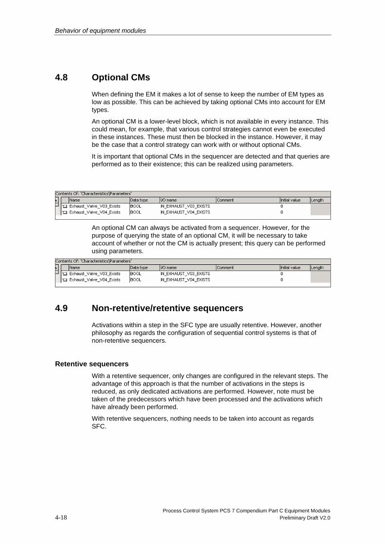
When defining the EM it makes a lot of sense to keep the number of EM types as low as possible. This can be achieved by taking optional CMs into account for EM types.
An optional CM is a lower-level block, which is not available in every instance. This could mean, for example, that various control strategies cannot even be executed in these instances. These must then be blocked in the instance. However, it may be the case that a control strategy can work with or without optional CMs.
It is important that optional CMs in the sequencer are detected and that queries are performed as to their existence; this can be realized using parameters.
An optional CM can always be activated from a sequencer. However, for the purpose of querying the state of an optional CM, it will be necessary to take account of whether or not the CM is actually present; this query can be performed using parameters.
4.9 Non-retentive/retentive sequencers
Activations within a step in the SFC type are usually retentive. However, another philosophy as regards the configuration of sequential control systems is that of non-retentive sequencers.
Retentive sequencers With a retentive sequencer, only changes are configured in the relevant steps. The advantage of this approach is that the number of activations in the steps is reduced, as only dedicated activations are performed. However, note must be taken of the predecessors which have been processed and the activations which have already been performed.
With retentive sequencers, nothing needs to be taken into account as regards SFC.

Behavior of equipment modules
Process Control System PCS 7 Compendium Part C Equipment Modules Preliminary Draft V2.0 4-19
Non-retentive sequencers With a non-retentive sequencer, all activations are set in each step. This means that the activations being performed can be tracked in every step, which greatly improves clarity.
To implement a non-retentive sequencer, the activations must be set on the “Initialization” tab and reset on the “Termination” tab in every step in the sequencer.
This does, however, mean increased configuration work.
4.10 Setting posi texts
Posis are set in the corresponding steps. The relevant numbers, which must be defined in the characteristics in advance, are assigned to the POSINO input.
As the posi texts are displayed in the EM faceplate, it makes sense to use them in the sequencer. However, the same posi number can also be assigned to associated steps within a sequencer.

Behavior of equipment modules
Process Control System PCS 7 Compendium Part C Equipment Modules 4-20 Preliminary Draft V2.0
4.11 Self-terminating vs. non-self-terminating equipment modules
There are two basic ways of terminating an EM: self-terminating and non-self-terminating EM.
The SFC type can cope with both termination methods, with the configuration being set via the SELFCOMP input. This input changes the termination behavior of the active sequencer in the SFC type.
Self-terminating EM An example of a self-terminating EM is a dosing procedure; once the procedure is complete, the EM will be terminated automatically.
Non-self-terminating EM An example of a non-self-terminating EM is a mixing procedure.
If the SELFCOMP input is configured with 0 (false), the SFC remains in the Run state and sets the READY_TC output. The EPH waits to be terminated in this state. In this case, no sequencer is active.
If the sequencer is to remain active while retaining the same behavior, a transition must be inserted.
In this case, a higher-level control must be informed that the EM has performed its task. This is reported via the READY_TC output, which must be set in a step.
In this case, a transition should be used as a subsequent condition which will never be met, to ensure that the sequencer remains active and can continue running.

Behavior of equipment modules
Process Control System PCS 7 Compendium Part C Equipment Modules Preliminary Draft V2.0 4-21
A condition which will never be met can be selected in such a way that it is still meaningful. For example, the Completing state can be used to terminate the sequencer. However, the condition is never met as the active sequencer is exited before the transition to Completing is executed, meaning that the condition is no longer active.
Behavior of equipment modules
Process Control System PCS 7 Compendium Part C Equipment Modules 4-22 Preliminary Draft V2.0
4.12 Returns when resuming
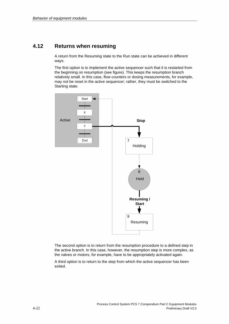
A return from the Resuming state to the Run state can be achieved in different ways.
The first option is to implement the active sequencer such that it is restarted from the beginning on resumption (see figure). This keeps the resumption branch relatively small. In this case, flow counters or dosing measurements, for example, may not be reset in the active sequencer; rather, they must be switched to the Starting state.
Holding
Resuming
Resuming / Start
Stop Active
7
8
9
Held
Start
End
X
Y
The second option is to return from the resumption procedure to a defined step in the active branch. In this case, however, the resumption step is more complex, as the valves or motors, for example, have to be appropriately activated again.
A third option is to return to the step from which the active sequencer has been exited.

Behavior of equipment modules
Process Control System PCS 7 Compendium Part C Equipment Modules Preliminary Draft V2.0 4-23
Example of a return in a defined step:
To enable a defined step to be returned to during resumption, the step must be defined while the active sequencer is being executed.
In the example, the process is to resume from step 2. The process is now held in step 3. On resumption, step 2 must be entered as the resumption step.
Holding
Resuming
Resuming / Start
Stop Active
7
8
9
Held
Start
End
1
2
3
4
Step flags (FL_SEQ, FL_STEP), in which the current step (CUSEQ, CUSTEP) can be saved, are defined for this purpose. Data types which are not available in the characteristics are required for this, so the flags must be defined in the I/O view.

Behavior of equipment modules
Process Control System PCS 7 Compendium Part C Equipment Modules 4-24 Preliminary Draft V2.0
In step 2 the defined step flags are set (this is the step which will be returned to during resumption).
If the process is now to be resumed in the Held state, the return is entered in the resumption sequencer.

Behavior of equipment modules
Process Control System PCS 7 Compendium Part C Equipment Modules Preliminary Draft V2.0 4-25
If the active sequencer starts, a jump will be performed to the resumption step which has been set. However, a prerequisite is that the sequencer in the Resuming state and that in the Run state are not the same.
4.13 Changing the faceplate
There is a default OS faceplate for the SFC type. The faceplate settings, such as those relating to colors, apply to all types. If type-specific changes are to be made, they must be based on the default faceplate.
Examples of changes to the default faceplate:
• Additional buttons for calling interlocking blocks
• Additional buttons for calling Help
• Additional view with a CM list
4.13.1 CM list
An EM often requires a CM list, which contains the available CMs, their current states, and a button for CM selection, for example. This can be integrated in the faceplate as an additional view, or called as a standalone faceplate.

Behavior of equipment modules
Process Control System PCS 7 Compendium Part C Equipment Modules 4-26 Preliminary Draft V2.0
4.13.2 Additional buttons in the SFC type faceplate
Additional buttons can be used to display the state of the closing or resumption lockout, for example, and to call the appropriate interlocking module, if necessary.
This is incorporated in the faceplate header (@PG_@SFC_TYP_HEAD.PDL). This section is always visible in the faceplate. The buttons can be located underneath the state change buttons, for example.

Behavior of equipment modules
Process Control System PCS 7 Compendium Part C Equipment Modules Preliminary Draft V2.0 4-27
4.14 Calculations
Calculations cannot be performed directly in the SFC type’s step sequencer. To realize calculations, I/O elements must be created at the interface. These elements contain the results of calculations and can, therefore, be used in steps or transitions. Calculations are implemented by means of direct instance interconnection or by creating a project-specific block (e.g. in SCL).-{}-
The advantage of having a separate block is that the type/instance concept can be implemented. However, it is more complex to create and, as a result, is only worthwhile for more complicated calculations.
If these calculations are not required in every step, it may be advisable to disable them in accordance with the current step, which is easier to do in a separate block.

Behavior of equipment modules
Process Control System PCS 7 Compendium Part C Equipment Modules 4-28 Preliminary Draft V2.0
4.15 Combining sequencers
Which actions are to be realized in each state must be defined for every control strategy of an EM. For example, if there are five control strategies and 16 SFC states, this results in a not inconsiderable number of sequencers (even when you take into account the fact that in some states no sequencers are implemented).
As an SFC type may contain a maximum of 32 sequencers, they must be sensibly combined. This can be done in several ways:
• Combination on the control strategy level
• Combination on the state level
• Combination of both methods
Operating modes Control strategy 1Control strategy 2Control strategy 3 Control strategy 4 Control strategy 5
IDLE
RUNNING
COMPLETING
COMPLETED
HOLDING
HELD
RESUMING
ERROR
HELD(Error)
RESUMING(Error)
ABORTING
ABORTED
Grouping of a sequence on equipment phase
Gro
upin
g of
a s
eque
nce
on O
SL
phas
e
S1S3
S0
S1S3
S0
S1S3
S0
S1S3
S0
S1S3
S0
S1S3
S0
S1S3
S0
S1S3
S0
S1S3
S0
S1S3
S0
S1S3
S0
S1S3
S0
S1S3
S0
S1S3
S0
S1S3
S0
S1S3
S0
S1S3
S0
S1S3
S0
S1S3
S0
S1S3
S0
S1S3
S0
S1S3
S0
S1S3
S0
S1S3
S0
S1S3
S0
S1S3
S0
S1S3
S0
S1S3
S0
S1S3
S0
S1S3
S0
S1S3
S0
S1S3
S0
S1S3
S0
S1S3
S0
S1S3
S0
S1S3
S0
S1S3
S0
S1S3
S0
S1S3
S0
S1S3
S0
S1S3
S0
S1S3
S0
S1S3
S0
S1S3
S0
S1S3
S0
S1S3
S0
S1S3
S0
S1S3
S0
S1S3
S0
S1S3
S0
S1S3
S0
S1S3
S0
S1S3
S0
S1S3
S0
S1S3
S0
S1S3
S0
Combination on the control strategy level means that there is a sequencer for every control strategy, with branches to the different states within this sequencer.

Behavior of equipment modules
Process Control System PCS 7 Compendium Part C Equipment Modules Preliminary Draft V2.0 4-29
A rigid combination according to control strategies or states does have its disadvantages, however, and cannot be sustained if RUNHOLD = FALSE (resumption if a step is held in RUN). In this case, it would make more sense to use a combination of the two methods.
The states containing sequences specific to a control strategy (e.g. STARTING, RUN, etc.) must be combined in a control strategy sequencer. States which contain the same sequence in every control strategy (e.g. ERROR) can be combined to form a sequencer. It is also often the case that the same sequence is performed in different states (e.g. Completing and Stopping).
Behavior of equipment modules
Process Control System PCS 7 Compendium Part C Equipment Modules 4-30 Preliminary Draft V2.0
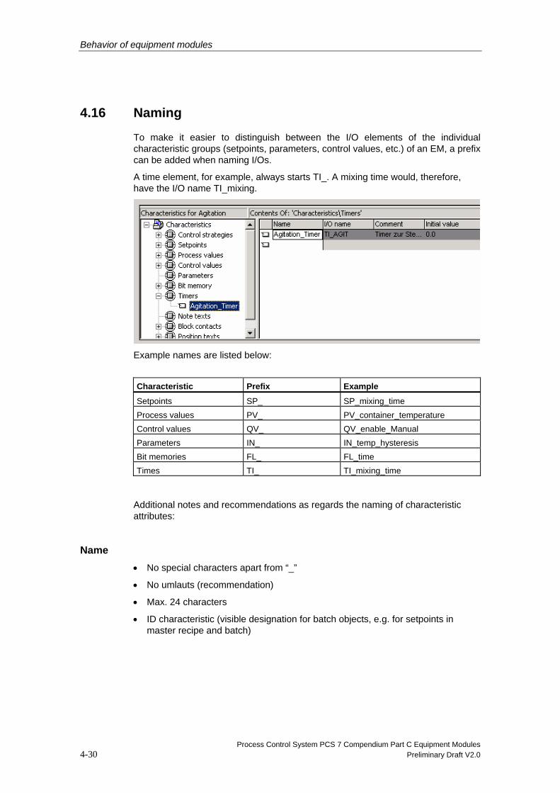
4.16 Naming
To make it easier to distinguish between the I/O elements of the individual characteristic groups (setpoints, parameters, control values, etc.) of an EM, a prefix can be added when naming I/Os.
A time element, for example, always starts TI_. A mixing time would, therefore, have the I/O name TI_mixing.
Example names are listed below:
Characteristic Prefix Example
Setpoints SP_ SP_mixing_time Process values PV_ PV_container_temperature Control values QV_ QV_enable_Manual Parameters IN_ IN_temp_hysteresis Bit memories FL_ FL_time Times TI_ TI_mixing_time
Additional notes and recommendations as regards the naming of characteristic attributes:
Name • No special characters apart from “_”
• No umlauts (recommendation)
• Max. 24 characters
• ID characteristic (visible designation for batch objects, e.g. for setpoints in master recipe and batch)

Behavior of equipment modules
Process Control System PCS 7 Compendium Part C Equipment Modules Preliminary Draft V2.0 4-31
Data type • Relevant for the following data types: BOOL, INT, DINT, REAL, PI, PO, String
• PI and PO are analog values for process inputs and outputs with the additional attributes “Material” and “Batch ID”. The value range and unit of measurement are read by the recipe system.
I/O name Length:
• Setpoints and times <= 16 characters
• Block contact <= 10 characters
• All other characteristics <= 24 characters
Remark
When the interface is generated, suffixes are added to the names of the automatically created I/Os for setpoints, times, and block contacts. When selecting names, remember that only the first eight characters of all contacts can be viewed simultaneously in CFC.
Long I/O names are only visible in full as tooltip texts.
To ensure that names remain distinguishable, unique, and uniform, it is best to define a naming convention at the start of configuration work.
Comment • Maximum length: 80 characters
• Only visible in the characteristics dialog
• Value range (low and high limit: <I/O name>_LL and <I/O name>_HH):
• Relevant for the following data types: INT, DINT, REAL, PI, PO
• Can be edited in the instance block for data types
Initial value • Default setpoint value
• Can be set on an instance-specific basis within the value range already defined
Text length • Relevant for the String data type
• Can be defined within the value range [1,254]

Behavior of equipment modules
Process Control System PCS 7 Compendium Part C Equipment Modules 4-32 Preliminary Draft V2.0
Precision • Relevant for the REAL, PI, and PO data types
• Determines the number of decimal places to be displayed
• Can be set to between 0 and 7
Unit • Relevant for the following data types: INT, DINT, REAL, PI, PO
• Defined in shared declarations
• Can be edited on an instance-specific basis in the “S7_unit” system attribute
Text0 and Text1 • Relevant for the BOOL data type
• Can be edited at the instance as the “S7_string1” or “S7_string0” system attribute
• Defined in shared declarations
• Not displayed in Batch
Enumeration Relevant for the BOOL, INT, and DINT data types
Can be edited at the instance as the “S7_enum” system attribute
Defined in shared declarations
Archiving Possible settings:
• No archiving (S7_archive := 'false')
• Archiving (S7_archive := 'shortterm')
• Long-term archiving (S7_archive := 'longterm')
• Can be edited on an instance-specific basis for I/Os with S7_m_c = ‘true’

Behavior of equipment modules
Process Control System PCS 7 Compendium Part C Equipment Modules Preliminary Draft V2.0 4-33
4.17 Start conditions for sequencers
The states in which the sequencer is to be started must be defined in the sequencer start conditions. These conditions form the basis of the relationship between the state logic and the sequencers.
In some states, executing the final step of a sequencer results in a state change (implicit), such as Starting, Holding, etc.; but in other states this is not the case. In these states the start conditions naturally remain active, so the sequencer is started over again. However, this is undesired in most cases.
This must be taken account of in the start conditions. The READY_TC output, which is set by the active branch following the first run, can be used here for the Run state.
You will find two examples of SFC types, along with their required transient state start conditions, in the SFC Library.
The types are TypeCtrlStrategy (FB 1026) and TypeStates (FB 1025).

Behavior of equipment modules
Process Control System PCS 7 Compendium Part C Equipment Modules 4-34 Preliminary Draft V2.0
4.18 Tips and tricks
4.18.1 Editing within the project
SFC types can be created in projects as well as in libraries.
As changes to an SFC type apply to all instances, for many instances it can make sense to change the SFC types in a library during configuration and then to transfer them to the project; this makes the editing process faster and ensures that data is consistent in the multiproject.
Another option is to create a small test project where the SFC types and an instance of each are saved. The SFC types can be tested in this project prior to use, before they are copied over to the actual project.
4.18.2 Block size of an SFC type
The block size of an SFC type depends on many factors (number of setpoints, control values, sequencers, steps, whether many REAL or BOOL setpoints are used, etc.) and combinations thereof.
In theory, it is possible to make calculations in advance using a formula contained in the PCS 7 documentation; this usually fails, however, as the necessary details (number of steps, for example) are not known at the outset.
The maximum block size is 64 KB. The actual block size of an SFC type can be determined using its FB + FCs in the block folder. If the equipment phase exceeds the block size, it will be necessary to divide the phase up.
Behavior of equipment modules
Process Control System PCS 7 Compendium Part C Equipment Modules Preliminary Draft V2.0 4-35
4.18.3 SFC type following AS stop/restart
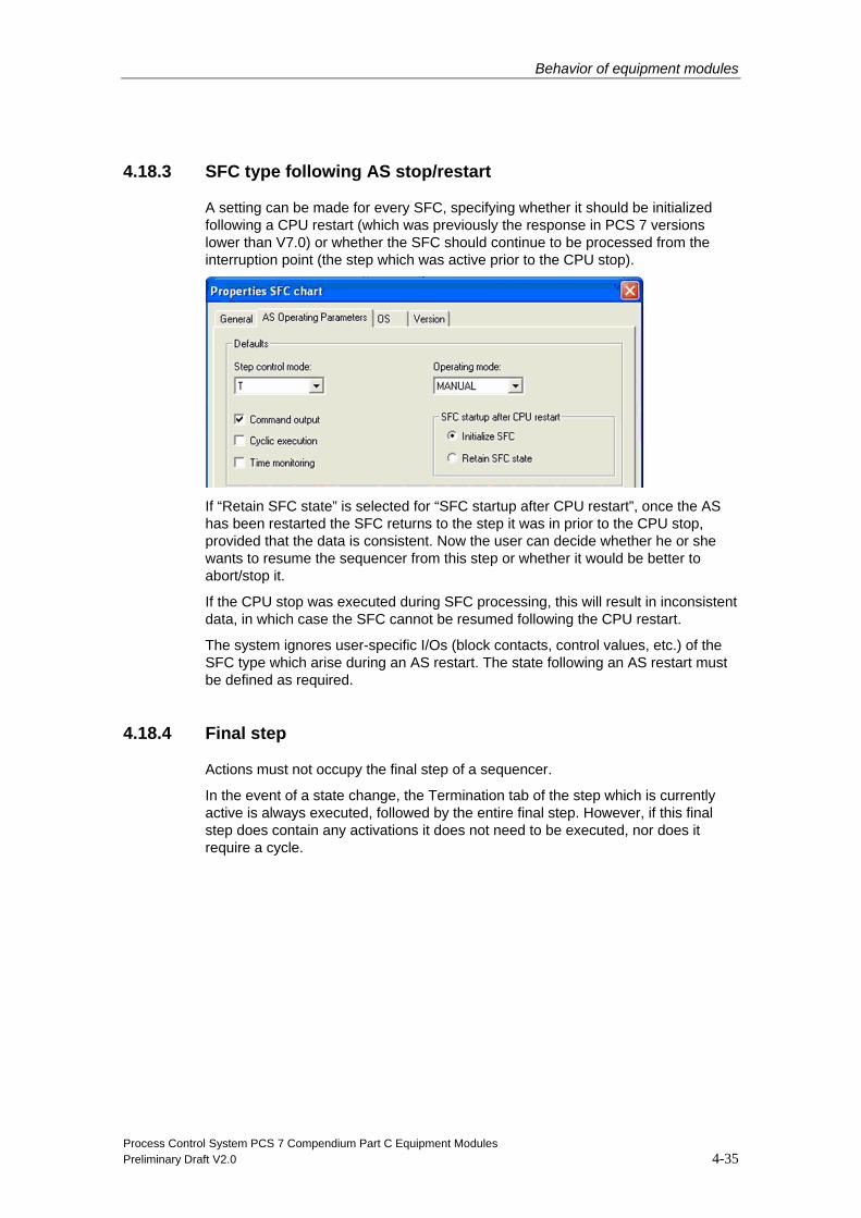
A setting can be made for every SFC, specifying whether it should be initialized following a CPU restart (which was previously the response in PCS 7 versions lower than V7.0) or whether the SFC should continue to be processed from the interruption point (the step which was active prior to the CPU stop).
If “Retain SFC state” is selected for “SFC startup after CPU restart”, once the AS has been restarted the SFC returns to the step it was in prior to the CPU stop, provided that the data is consistent. Now the user can decide whether he or she wants to resume the sequencer from this step or whether it would be better to abort/stop it.
If the CPU stop was executed during SFC processing, this will result in inconsistent data, in which case the SFC cannot be resumed following the CPU restart.
The system ignores user-specific I/Os (block contacts, control values, etc.) of the SFC type which arise during an AS restart. The state following an AS restart must be defined as required.
4.18.4 Final step
Actions must not occupy the final step of a sequencer.
In the event of a state change, the Termination tab of the step which is currently active is always executed, followed by the entire final step. However, if this final step does contain any activations it does not need to be executed, nor does it require a cycle.

Behavior of equipment modules
Process Control System PCS 7 Compendium Part C Equipment Modules 4-36 Preliminary Draft V2.0
4.18.5 EPH/EOP
When an SFC type is created, its purpose (category) can be specified in the properties.
The following categories are available for selection:
• None
• EPH (equipment phase)
• EOP (equipment operation)
The difference between EOP and EPH becomes apparent in the recipe editor. If EPH is selected, a corresponding RPH is generated in the batch system. This RPH can be used in the recipe editor as part of recipe operations.
If EOP is selected, a closed recipe operation which can be used on the operation level in recipes is generated on the recipe level. This makes sense if the corresponding unit does not offer any greater flexibility anyway.
If the SFC type is not to have a SIMATIC BATCH interface, “None” must be set here.

Behavior of equipment modules
Process Control System PCS 7 Compendium Part C Equipment Modules Preliminary Draft V2.0 4-37
4.18.6 Presetting control strategies
To prevent the most recently executed control strategy being offered as a new control strategy on startup, a control strategy can be defined as the "Default".
Once the SFC has been executed, the control strategy selected as the default is automatically offered for the SFC faceplate’s “Prepare control strategy” setting.
4.18.7 Instance-specific deselection/selection of control strategies
When the type/instance model is used, it may be necessary to deselect control strategies or sequences on an instance-specific basis in order to limit the number of different types, as the required equipment may not be present.
For example, for an acid dosing type a certain amount of substance can be provided (control strategy 1) and a pH value set (control strategy 2) for the dosing procedure.
Therefore, if an equipment module/phase on a unit is only designed for dosing an amount of acid (pH measurement not available), it will be necessary to deselect control strategy 2 on the instance.
This brings with it the advantage that another type does not have to be created or maintained.

Behavior of equipment modules
Process Control System PCS 7 Compendium Part C Equipment Modules 4-38 Preliminary Draft V2.0
4.18.8 Connecting to BATCH
For an SFC type, the connection to BATCH is carried out directly via the definition of the SIMATIC BATCH category (see 4.18.5 “EPH/EOP”). SIMATIC BATCH is able to read out the configured batch characteristics (control strategies and setpoints) of an SFC type directly, as well as the associated instances. This means that no additional interface blocks are needed for an SFC type.
4.18.9 Multiple instances of a type in a unit
SIMATIC BATCH stipulates that only one instance of an SFC type can be created per unit; however, this restriction can be circumvented in various ways.
One way is to copy an SFC type, although this does require additional configuration work if subsequent changes are made or qualification steps carried out.
The SFC type can also be connected via the BATCH interface blocks (IEPH, IEPAR_xx) as well. In this case, the SFC type category must be set to “None”, so that SIMATIC BATCH does not identify it as an EPH or EOP type. However, this method also calls for additional configuration work, although qualification measures may be able to be reduced.

Behavior of equipment modules
Process Control System PCS 7 Compendium Part C Equipment Modules Preliminary Draft V2.0 4-39
4.18.10 Closing lockout, start disable for SIMATIC BATCH
It is possible to disable or interlock the start of an equipment phase from SIMATIC BATCH via input BA_EN = FALSE.
If the phase is then enabled for SIMATIC BATCH (BA_EN = TRUE), the recipe procedure can continue to be executed on resumption.
4.18.11 Start disable/resumption lockout for SIMATIC BATCH for equipment phases previously started manually
In general, SIMATIC BATCH cannot start or occupy any EPH in Manual mode.
However, if an EPH is started manually intentionally and then switched back to Automatic mode, this is carried out in accordance with the configuration and operating state logic.
If during the recipe procedure a control recipe comes across a point where this previously started EPH is required or must be started, this phase is occupied by SIMATIC BATCH and the control state is transferred. The phase is not described using the recipe control strategy and recipe setpoints, as the manual specifications have priority.
Please note that the control strategies/setpoints which are present prior to the recipe start of the phase are not transferred to the batch log.
However, in projects it is sometimes the case that this system functionality is not wanted and it must be interlocked as described below by means of the configuration.
In this case, an interlock is also useful for synchronization lines in the recipe, if there is a requirement that all phases below the synchronization level must have a start enable and switch to the Starting [2] state at the same time.
Otherwise, the synchronization condition is met by the system if all subsequent phases show BA_EN = TRUE and OCUPPIED = TRUE.

Behavior of equipment modules
Process Control System PCS 7 Compendium Part C Equipment Modules 4-40 Preliminary Draft V2.0
4.18.12 Continuous function
The Continuous function is intended for recipe creation and batch control in SIMATIC BATCH.
Continuous is frequently used for non-self-terminating phases (e.g. mixing).
Non-self-terminating phases are not terminated by means of conditions (level reached), but rather by means of operator input or a higher-level recipe system (see also Chapter 4.11“Self-terminating vs. non-self-terminating equipment modules“).
In a recipe system, however, it is not always required to switch off a mixer, for example, between two recipe steps; rather, you may want to let the mixer continue to run at a different speed.
The behavior of the state logic must be taken into account during configuration in order to implement this function.
If the Continuous function is selected in the recipe, the next time the phase is started from within the recipe it will not pass through the transition states Completing [4], Completed [6], etc. until it reaches Run [3]; rather it will switch directly from Run [3] to Starting [2].
It must be noted, therefore, in which transition states or sequencer steps the motor for the mixer, for example, is switched off.
The Continuous function is only available for non-self-terminating phases.

Behavior of equipment modules
Process Control System PCS 7 Compendium Part C Equipment Modules Preliminary Draft V2.0 4-41
STARTING
Completing
Continuousoperation
Starting
Ready
Completed
Active
1
2
3
6
4