engineering and manufacturing for motion control … · step 1 – choosing a motor size (force...
TRANSCRIPT

ENGINEERING AND MANUFACTURING FOR MOTION CONTROL PRODUCTS
ENGINEERING AND MANUFACTURING M
OTION CONTROL MOTOR PRODUCTS
DINGS' ELECTRICAL &MECHANICAL Co., Ltd.
20182019 ver.2.7
UK Business Partner: Motion Control Products Ltd.

Combining more than 50 years of experience in the precise motor products for motion control industry, with manufacturing facility located in China and the United States, and service and supporting centers worldwidely, DINGS’ provides a supply chain that allows us to deliver quality, cost effective product solutions to our customers in Asia, North America and Europe. Our ability is to create innovative custom solutions allows us the flexibility to meet your diverse applications.
We now offer a broad range of precision linear motion products, hybrid stepping motors, Brush and brushless DC motors. All our products offer high performance in demanding applications such as laboratory automation, Bio-medical instrumentation, semiconductor fabrication and various industrial applications.
For more information on our products and the latest news, please visit our website:
www.dingsmotion.com
Or contact DINGS’ technical supports and your local DINGS’ representatives.
INTRODUCTION OF DINGS’
www.dingsmotion.com

www.dingsmotion.com
WARRANTY
Twenty Four Month Limited Warranty
DINGS’ warrants our products delivered hereunder to confirm to stated specifications and to be free from defects in materials and workmanship. This warranty shall not apply to any product which shall have been improperly installed or subjected to misuse or neglect or which has been repaired or altered except by seller’s accredited representative, nor to any product which has been subjected to accident.
DISCLAIMER
The information in this catalog has been carefully checked and is believed to be accu-rate; however, no responsibility is assumed for inaccuracies.DINGS’ reserves the right to make changes without further notice to any products herein to improve reliability, function,or design.DINGS’ does not recommend the use of its products in life support or aircraft appli-cations wherein a failure or malfunction of the product may directly threaten life or injury.

www.dingsmotion.com
General CatalogA
Hybrid Stepper Motor Lead Screw Linear Actuators
Hybrid Stepper Motor Ball Screw Linear Actuators
PM Stepper Linear Actuators
Stepper Motor Linear Actuator A-0
A-1
A-60
A-83

www.dingsmotion.com
B
C
D
E
Hybrid Rotary Stepper Motor
Hollow Shaft Hybrid Stepper Motor
Brushless DC Motor
Stepper Motor Driver
B-1
C-1
D-1
E-1

www.dingsmotion.com
Stepper Motor Linear Actuator
TABLE of ConTEnTS
Hybrid stepper motor lead screw linear actuators
Part number construction
Lead screw code selection
Product selection guide
Technology overview
General specifications
Size 8 · 20 mm series
Size 11 · 28 mm series
Size 14 · 35 mm series
Size 17 · 42 mm series
Size 23 · 57 mm series
Size 24 · 60 mm series
Size 34 · 86 mm series
Accessories and options
Installation guide
Hybrid stepper motor ball screw linear actuators
Part number construction
Ball screw lead code selection
Size 8 · 20 mm series
Size 11 · 28 mm series
Size 14 · 35 mm series
Size 17 · 42 mm series
Size 23 · 57 mm series
Accessories and options
Installation guide
PM stepper linear actuators
Part number construction
Product overview
20 mm series
25 mm series
36 mm series
A-2
A-3
A-4
A-5
A-11
A-12
A-16
A-20
A-26
A-32
A-38
A-44
A-47
A-58
A-61
A-62
A-63
A-66
A-69
A-72
A-75
A-78
A-81
A-84
A-85
A-86
A-90
A-94

www.dingsmotion.com
Brushless DC Motor
Stepper Motor Driver
Hybrid Rotary Stepper Motor
Hollow Shaft Hybrid Stepper
Part number construction
Product overview
Size 8 · 20 mm series
Size 11 · 28mm series
Size 14 · 35 mm series
Size 17 · 42 mm series
Size 23 · 57 mm series
Size 24 · 60 mm series
Size 34 · 86 mm series
Accessories and options
Part number construction
Product overview
Size 8 · 20 mm series
Size 11 · 28mm series
Size 14 · 35 mm series
Size 17 · 42 mm series
Size 23 · 57 mm series
Size 34 · 86 mm series
DS-2422-001
DS-5045-003
DS-2MSD8078-2
DS-OL17/23-I series
ST-484 closed-loop driver
Vector series integrated driver
DS-CL28-SA Integrated closed-loop driver
B-2
B-3
B-4
B-6
B-8
B-10
B-12
B-14
B-16
B-18
C-2
C-3
C-4
C-6
C-8
C-10
C-12
C-14
E-2
E-3
E-4
E-5
E-11
E-13
E-18
Part number construction
Size 17 · 42 mm series
Size 23 · 57 mm series
Size 24 · 60 mm series
Size 34 · 86 mm series
D-2
D-3
D-4
D-5
D-6

A Stepper Motor Linear ActuatorDINGS’ offers a unique line of stepper motor linear actuators that open new avenues for equipment designers who require high performance and exceptional endurance in a very small package. The various products convert the rotation movement to linear motion directly on motor, with engineering thermoplastics nut and a stainless steel acme lead screw. This allows the linear actuator to provide quiet, efficient, durable and cost effective linear motion solutions.These linear actuators are ideal for applications requiring a combination of precise positioning, rapid motion and long life. Typical applications include X-Y tables, medical equipment, semiconductor handling, telecommunica-tions equipment, valve control, and numerous other uses.Variety of customizations upon to request, such as different screw length, special design nut, anti-backlash nut, safety brake, encoder and others. For higher efficiency and extreme long life and high precision applications, DINGS’ provides the linear actuator with different grade of ball screw at reasonable cost.
A-0
www.dingsmotion.com

Hybrid Stepper Motor Lead Screw Linear Actuators
Part number construction
Lead screw code selection
Product selection guide
Technology overview
General specifications
Size 8 · 20mm series
Size 11 · 28mm series
Size 14 · 35mm series
Size 17 · 42mm series
Size 23 · 57mm series
Size 24 · 60mm series
Size 34 · 86mm series
Accessories and options
Installation guide
The DINGS’ of hybrid linear actuators come in six sizes, from 20 mm square to 86 mm square corresponding to size
8, size 11, size 14, size 17, size 23, and size 34. Each size has four designs available-Captive, Non-captive, Kaptive
and an External linear version. There are over twenty different travels per step available, from. 00006 inch (.001524
mm) to .005 inch (.127 mm). Micro stepping can be used for even finer resolution.
www.dingsmotion.com
A-1
A-2
A-3
A-4
A-5
A-11
A-12
A-16
A-20
A-26
A-32
A-38
A-44
A-47
A-58
DINGS' ELECTRICAL &MECHANICAL Co., Ltd.

www.dingsmotion.com
A-2
EXAMPLE
Part number 17N2115K4-101.6TMSEK2
Description Nema 17 Non-captive Linear Actuator 2 Phase with 1.8 Degree Step Angle Single Stack 1.5A / Phase “K” Lead (0.1”/2.54mm) 4 Flying Leads Screw Length: 101.6mm Teflon Coated Screw Metric End Machining Standard Nut EK2 Encoder with Single Output, 192 lines
Part Number Construction
17N 2 1 15 K 4 101.6 T M EK21 2 3 4 5 6 7 8 9 10 11
8
20
11
28
14
35
17
42
23
57
34
86
1 Motor Size CODE MOTOR SIZE (mm)2 Linear Actuator Type E = External Linear N = Non-captive linear C = Captive linear K = Kaptive linear3 Step Angle 2 = 2 Phase with 1.8° 4 = 2 Phase with 0.9° 3 = 3 Phase with 1.2° 5 = 5 Phase with 0.72°4 Motor Length / Stack 1 = Single Stack 2 = Double Stack5 Rated Current/Phase XX = X.X (A)/Phase6 Lead Screw Code
7 Number of Lead Wires 4 = Qty 4 Flying Leads 6 = Qty 6 Flying Leads 8 = Qty 8 Flying Leads8 Lead Screw Length / Stroke XXX = XXX mm Lead screw length (For External Linear/Non-Captive Linear) XXX = X.XX inch Stroke (For Captive & Kaptive Linear)
9 Lead Screw Surface Treatment T = Teflon Coating S = Standard (No Teflon Coating)10 End Machining M = Metric U = UNC S = Smooth C = Customize N = None11 Nut Style S = Standard Flange Nut A = Anti-Backlash Nut C = Customized Nut12 Encoder Option EKX = Encoder (XX = Encoder Code) B = Brake X = Rear Shaft R = Encoder Ready (Hole and Shaft) C = Customize N = None R20 = RMB20SC10BC10 for size8 R28 = RMB28SC10BC10 for size1113 Customer Sequence Number
00113
S12

www.dingsmotion.com
A-3
20
Φ3.5(0.138˝)
Φ4.77(0.188˝)
Φ5.56(0.218˝)
Φ6.35(0.25˝)
Φ9.525(0.375˝)
Φ10(0.394˝)
Φ15.875(0.625˝)
Φ8(0.315˝)
LeadCode
1.8 Degree Motor Travel
per Step inch(mm)
Motor Size (mm)
Screw Dia. mm(inch)28 35 42 57 86
AL
AA
A
B
D
F
H
J
K
L
P
Q
R
S
U
UA
V
W
X
Y
Z
AF
AB
G
M
T
0.000063˝ (0.001588)0.00012˝(0.003048)0.000125˝ (0.003175)0.00024˝ (0.006096)0.00025˝ (0.00635)0.0003125˝ (0.0079375)0.000417˝ (0.010583)0.00048˝(0.012192)0.0005˝(0.0127)0.000625˝ (0.015875)0.000833˝ (0.021167)0.00096˝ (0.024384)0.001˝ (0.0254)0.00125˝(0.03175)0.001665˝ (0.042291)0.0016667˝(0.042333)0.001875˝ (0.047625)0.00192˝ (0.048768)0.002˝ (0.0508)0.0025˝ (0.0635)0.005˝ (0.127)0.00015 (0.000059˝)0.005(0.000197˝)0.01 (0.000394˝)0.02 (0.000787˝)0.04 (0.001575˝)
0.024˝(0.6096)
0.048˝(1.2192)
0.3(0.0118˝)1.0(0.0394˝)2.0(0.0787˝)4.0(0.1575˝)8.0(0.3150˝)
0.0125˝(0.3175)
0.025˝(0.635)
0.05˝(1.27)
0.1˝(2.54)
0.2˝(5.08)
0.4˝(10.16)
0.024˝(0.6096)
0.048˝(1.2192)0.05˝(1.27)0.0625˝(1.5875)
0.096˝(2.4384)0.1˝(2.54)0.125˝(3.175)
0.192˝(4.8768)
0.25˝(6.35)0.333˝(8.4582)0.3333˝(8.4667)
0.384˝(9.7536)
0.5˝(12.7)
1.0(0.0394˝)
0.025˝(0.635)
1.27(0.05˝)0.0625˝(1.5875)0.083˝(2.1167)
0.1˝(2.54)0.125˝(3.175)0.167˝(4.2333)
0.2˝(5.08)0.25˝(6.35)
0.375˝(9.525)0.384˝(9.7536)0.4˝(10.16)0.5˝(12.7)1˝(25.4)
0.1˝(2.54)0.125˝(3.175)
0.2˝(5.08)0.25˝(6.35)
0.5˝(12.7)1˝(25.4)
2.0(0.0787˝)
0.083˝(2.1167)
2.0(0.0787˝)4.0(0.1575˝)8.0(0.3150˝)
0.096˝(2.4384)
0.192˝(4.8768)
Lead Screw Code Selection
* Remarks: 8mm diameter of lead screw of 35, 42 and 57mm is not applicable for Non-Captive and Anti-Backlash Nut *

www.dingsmotion.com
A-4
To reduce complexity and cost of a design, it is important to accurately size a motor/lead screw combination. Belows are a few simple steps in selecting the necessary compotents for a given application.
Step 1 – ChooSing a motor Size (ForCe requirementS)Here is a general overview of the output thrust vs. motor size:
motor Sizes(mm) max thrust(n) recommended Load Limit(n)
Hybrid stepper motor based linear actuators
20 70 45
28 150 140
35 300 230
42 600 230
57 1300 910
86 2400 2270
Step 2 – ChooSing a SCrew Lead (ForCe and Speed requirementS)
After estimating the required thrust and choosing a motor size that may fit your application, the speed and acceleration of the load must be considered and evaluated to choose an appropriate screw lead.
Due to the nature of lead screws, the output speed and output thrust achievable by a motor/lead screw combination are two inversely proportional variables. (i.e.,increasing the required thrust will lower the achievable speed for a motor/lead screw combination). Therefore, the maximum output force of a system is lowered for applications that requires higher speed.
For complete motor/lead screw selection data, please refer to the speed/thrust curves for each motor size.
Although these two steps provide a solid foundation in motor/lead screw selection, other variables must also be considered:
·Duty Cycle·Desired Life of a System·Environmental Considerations·Positional Repeatability·Acceptable Backlash·Acceleration/Deceleration·Driver Specificatins·Vertical or Horizontal
Because of the numerous variables involved in motor selection, it is highly recommended for users to proceed with physical testing to accurately determine the motor/lead screw combination required for a given application.
note: Although this section aims to provide a rough guide line to select a motor/lead screw combination that best fits an application, we recommend to contact our application engineering staff or sales representatives for further assistance with the motor selection process.
FOR MORE INFOMATION, CONTACT YOUR LOCAL DINGS’ REPRESENTATIVE (www.dingsmotion.com)
Product Selection Guide

www.dingsmotion.com
A-5
Technology Overview
A.External Linear’ B.Non-captive
C.Captive D.Kaptive
One of the most common methods of moving a load from point A to point B is through linear translation of a motor by a mechanical lead screw and nut. This section is here to assist and refresh your understanding of the basic principles of lead screw technology prior to selecting the system that is best for your application.Some basic design consideration are as follows:1. What is the load of your system?2. What is the required speed to move from point A to point B?3. What is the distance to be travelled? 4. What accuracy does your application require?5. What is the required time to move from point A to point B?6. What repeatability does your application require?7. Horizontal vs vertical orientation?
LinEAR ACTuAToR TYPES
TERMinoLoGYLEADLead is the axial distance the nut advances on one revolution of the screw. Throughout this catalog, lead will be the term used for revolution a screw as it is the linear distance travelled for one revolution of the screw. The larger the lead, the more linear distance travelled per one revolution of the screw. Lead = Pitch x screw start.
PiTCHPitch is the axial distance between threads. Pitch is equal to lead in a single start screw. There may be more than one thread “strand”on a single screw. These are called starts. Multiple start lead screws are usually more stable and efficient at power transmission.
ACCuRACY of SCREwSpecified as a measurement over a given length of the screw. For example: 0.004 inch per foot. Lead accuracy is the difference between the actual distance travelled versus the theoretical distance travelled based on the lead. For example: A screw with a 0.5 inch lead and 0.004 inch per foot lead accuracy rotated 24 times theoretically moves the nut 12 inches. However, with a lead accruracy of 0.004 inch per foot, actul travel could be from 11.996 to 12.004 inches.
PoSiTion ToLERAnCEThe approach value between actual distance travelled vs theoretical distance travelled.
REPEATABiLiTYMost motion applications put the most significance on the repeatability (vs accuracy of screw) of a system to reach the same commanded position over and over again.
HoRizonTAL oR VERTiCAL APPLiCATionVertical orientation applications add the potential problem of backdriving when power to the motor is off and without an installed brake. Vertical application also have an additional gravity factor that must be part of the load/force calculation.
ToTAL inDiCATED RunouTThe amount of “wobble”around the centerline of the screw.
TEnSion oR CoMPRESSion LoADA load that tends to stretch the screw is called a tension load.A load that tends to “squeeze”or compress the screw is called a compression load.Depending on the size of the load, designing the screw in tension utilizes the axial strength of the screw versus colomn loading.
ViBRATion AnD noiSEThe hybrid stepper motor’s resonance will be occured when pulse is up to 200PPS. Try starting your acceleration ramp at above these levels. Micro-stepping will also help through these ranges.

www.dingsmotion.com
A-6
STATiC LoADLoad applied to the screw when the screw is standstill.
DRiVERStepper motors require some external electrical components in order to run. These components typically include apower supply, logic sequencer, switching components and a clock pulse source to determine the step rate. Many commercially available drives have integrated these components into a complete package. Some basic drive units have only the final power stage without the controller electronics to generate the proper step sequencing.
DYnAMiC LoADLoad applied to the screw when the screw is moving.
HoLDinG ToRquEWhen motor is static and rated current is applied to two phase, the stator’s holding ability to the rotor.
RoToR inERTiAMoment matters when accelerate or decelerate.
TRAVEL PER STEPThe linear travel movement of one full step of the motor.
HEAT RiSinGMotor body’s temperature rising after certain periods running and heat exchange with the ambient.
RESPonSE PER STEPTimes takes to complete one step.
STEPCharacteristics of stepper motor that the rotor moves step by step as the stator commutates phase by phase.
STEP AnGLEAngular movement of every step.
PuLL ouT ToRquEUnder certain drive condition (frquency and current), the max load that the motor can drag until missing step
PuLL in ToRquEWhen couples and accelerates, the max load torque (including frictions) that the motor can bear and start.
EffiCiEnCYThe ability of a mechanial system to translate an input to an equal output.
RESoLuTionIncremental linear distance the actuator’s (motor) output shaft will move per input pulse.
Technology Overview

www.dingsmotion.com
A-7
TEnSion oR CoMPRESSion LoADinGA load that tends to stretch the screw is called a tension load.A load that tends to “squeeze” or compress the screw is called a compression load.Depending on the size of the load, designing the screw in tension utilizes the axial strength of the screw versus column loading.
RADiAL LoADA load perpendicular to the screw.This is not recommended unless additional mechanical support such as a linear guide is used.
Compression Loading Tension Loading
Radial Loading(Avoid or Minimize)
AXiAL LoADA load that exerted at the center line of the lead screw.
STATiC LoADThe maximum thrust load, including shock load, that should be applied to a non-moving screw.
DYnAMiC LoADThe maximum recommended thrust load which should be applied to the screw while in motion.
BACKDRiVinGBackdriving is the result of the load pushing axially on the screw or nut to create rotary motion. Generally, a nut with an efficiency greater than 50% will have a tendency to backdrive. Selecting a lead screw with an effciency below 35% may prevent backdriving. The smaller the lead, the less chance for backdriving or free wheeling. Vertical application is more prone to backdriving due to gravity.
ToRquEThe required motor torque to drive just the lead screw assembly is the total of:1. Inertial Torque2. Drag Torque (friction of the nut and screw in motion)3. Torque to move load
LuBRiCATionThe nut material contains a self-lubricating material that eliminates the need for adding a lubricant to the system. The Teflon coated screw option also lowers friction and extends life of the system.
EnD MACHininG of THE SCREw (Please refer to A-40)Standard metric or English option are available. Custom end machining specifications are also available on request. Please contact your local DINGS' representative.
Axial Center Loading(best)
Technology Overview

www.dingsmotion.com
A-8
fiXiTYThe performance (speed and efficiency) of the screw system is affected by how the screw ends are attached and supported.
CoLuMn STREnGTHWhen a screw is loaded in compression, its limit of elastic stability can be exceeded and the screw will fail due to bending or buckling.
CRiTiCAL SPEEDCritical speed is the rotational speed of the screw at which the first harmonic of resonance is reached due to deflection of the screw. A system will vibrate and become unstable at these speeds.
Several variables affect how quickly the system will reach critical speed: 1. The lead of the screw 2. The rotational speed 3. End fixity 4. Thrust load 5. Diameter of the screw 6. Tension or compression loading
For example, the following chart shows that for a screw with a 3/4 inch diameter and 70 inch length, the threshold for critical speed is 700RPM.
Type of End Fixity Relative Regidity
Critical Speed Factor
Critical Load Factor
Less Rigid
Rigid
More Rigid
Most Rigid
0.32
1.0
1.55
2.24
0.25
1.0
2.0
4.0
Technology Overview

www.dingsmotion.com
A-9
Standard Nut
BACKLASH IN BLUE BACKLASH IN BLUE BACKLASH IN BLUE
Lead screw Lead Screw Lead Screw
Nut Nut A Nut B Nut A Nut B
Tension Anti-Backlash Nut Compression Anti-Backlash Nut
Standard Nut
BACKLASH IN BLUE BACKLASH IN BLUE BACKLASH IN BLUE
Lead screw Lead Screw Lead Screw
Nut Nut A Nut B Nut A Nut B
Tension Anti-Backlash Nut Compression Anti-Backlash Nut
BACKLASHBacklash is the relative axial movement between a screw and nut at standstill. It is normal for backlash to increase with wear over tme. Backlash compensation or correction can be accomplished through the application or an anti-backlash nut. Backlash is usually only a concern with bi-directional positioning.
CRITICAL ROTATION SPEED (RPM) VS. UNSUPPORTED SCREW LENGTH FOR VARIOUS SCREW DIAMETERS (INCH)
Technology Overview

www.dingsmotion.com
A-10
STEPPING SEQUENCE
BiPoLAR uniPoLAR
extend CW
retr
act
CC
W
red
N S
green/white
red/white
green+V +V
Q2Q1
Q4Q3
Q6+V
Q5
Q8Q7
red
black
red/white whitegreen green/white
N S
Q1 Q4Q3Q2
Bipolar q2-q3 q1-q4 q6-q7 q5-q8
unipolar q1 q2 q3 q4
Step
1 on off on off
2 off on on off
3 off on off on
4 on off off on
5 on off on off
Technology Overview

www.dingsmotion.com
A-11
Unless otherwise noted, all reference to lead screws in this catalog have the following characterisitics
Lead Screw Material 303 Stainless precision cold rolled steel
Screw Coating Teflon coating is optional
Standard Screw Accuracy 0.0071 inch per foot (0.18mm per 300mm) (Lead accuracy)
Screw Straightness 0.08 inch/foot, measured as Total Indicated Runout(TIR). All screws are carefully checked for straightness before shipment.
Screw Efficiency From 35% to 85% dependent on lead. Also depends on the usage of an anti-backlash nut with screw. The larger the lead, the higher the efficiency of the screw.
Operating Temperature -20°C to + 50°C
Storage Temperature -20°C to + 50°C , keep in dry
Screw Backlash 0.01mm~0.1mm, depends on different lead. Anti-backlash nut should be considered for high bi- directional positioning repeatability.
System Backlash Includes screw, motor, and attached mechanics. This will be the sum of all the backlash in your motion axis.
Nut Material Polyacetal with lubricating additive; Standard is a free-wheeling nut. (Anti-backlash version is available)
Wear Life of Screw and Nut Depends on load, speed, duty cycle, and environmental factors (typically ≥ 5 million cycles)
NOTE: DINGS’ linear system are manufactured from high quality materials. Because of the variable effects of friction, lubrication, and cleanliness, an exact life cannot be predicted for a given applications.
FOR MORE INFOMATION, CONTACT YOUR LOCAL DINGS’ REPRESENTATIVE (www.dingsmotion.com)
General Specifications

www.dingsmotion.com
A-12
100 2 L 0.5
16 -0 0.05
1.5 0.2 15.4 0.15
20
4-M2 2Min
32020
4 leads
AWG #28
19.05
3- 3.2
12.7
6.35
2.54
15.5
REVISION
REV. DATE DESCRIPTION DRAWN BY
D
E
F
C C
D
Linear Actuator
常州市鼎智机电有限公司DINGS' MOTION
MFG'D 工艺
TITLE:
DATE 日期 线性步进电机
技术规格书SpecificationUNLESS OTHERWISE SPECIFIED:
其余未注事项:
尺寸单位为毫米(mm).
未注公差按以下标准:
毫米 mm英寸 inch
客户 Customer
Checkd 审核
Name 姓名
APPV'D 批准QA 质量
DRAWN 设计
角度 ±1°
视图 重要尺寸 ▲
何超
Screw Dia.(inch)
Screw Dia.(mm)
Lead(inch)
Lead (mm) Lead Code Travel Per Step
@ 1.8 deg (mm)*
0.138 3.5 0.0118 0.3 AF 0.0015
0.138 3.5 0.024 0.6096 AA 0.003
0.138 3.5 0.0394 1.0 AB 0.005
0.138 3.5 0.048 1.2192 B 0.0061
0.138 3.5 0.0787 2.0 G 0.01
0.138 3.5 0.1575 4.0 M 0.02
0.138 3.5 0.315 8.0 T 0.04
Motor Voltage(V)
Current(A)
Resistance (Ω)
Inductance(mH)
Weight (g)
Lead Wire No.
Motor Length (mm)
8-2105 2.5 0.5 5.1 1.5 51 4 27.2
8-2205 4.4 0.5 8.8 2.7 74 4 38.1
The size 8 is our smallest hybrid linear actuators. This compact unit can be integrated into various applications to provide precise linear positioning while occupying less than 1 in2 of mouting footprint and providing up to 45N of continuous thrust.
Dimensional Drawings External Actuator
noTE: All drawings are First Angle Projection – ISO Standard. (3D Models are available).
Motor Characteristics
Available Lead Screw and Travel per Step
Size 8 (20mm) Series
Value truncated

www.dingsmotion.com
A-13
4
100 1
L 0.5
1.5
M2.5x0.45
0.2
20
15.4 0.15
32020
4 leads
AWG #28
16 -0 0.05
4-M2 2Min
REVISION
REV. DATE DESCRIPTION DRAWN BY
D
E
F
C C
D
Linear Actuator
常州市鼎智机电有限公司DINGS' MOTION
MFG'D 工艺
TITLE:
DATE 日期 线性步进电机
技术规格书SpecificationUNLESS OTHERWISE SPECIFIED:
其余未注事项:
尺寸单位为毫米(mm).
未注公差按以下标准:
毫米 mm英寸 inch
客户 Customer
Checkd 审核
Name 姓名
APPV'D 批准QA 质量
DRAWN 设计
角度 ±1°
视图 重要尺寸 ▲
何超
100 2 L 0.5
16 -0 0.05
1.5 0.2 15.4 0.15
20
4-M2 2Min
32020
4 leads
AWG #28
19.05
3- 3.2
12.7
6.35
2.54
15.5
REVISION
REV. DATE DESCRIPTION DRAWN BY
D
E
F
C C
D
Linear Actuator
常州市鼎智机电有限公司DINGS' MOTION
MFG'D 工艺
TITLE:
DATE 日期 线性步进电机
技术规格书SpecificationUNLESS OTHERWISE SPECIFIED:
其余未注事项:
尺寸单位为毫米(mm).
未注公差按以下标准:
毫米 mm英寸 inch
客户 Customer
Checkd 审核
Name 姓名
APPV'D 批准QA 质量
DRAWN 设计
角度 ±1°
视图 重要尺寸 ▲
何超
Non-Captive Actuator
noTE: All drawings are First Angle Projection – ISO Standard. (3D Models are available).
Size 8 (20mm) Series
nut Dimensions

www.dingsmotion.com
A-14
32020
4 leads
AWG#28 4-M2 2min
15.4 0.14 20
16 -0 0.05
Φ13 L 0.5 A 0.5
0.5 1.3 0.2 10
4
C Max
3.5
B
D
E
F
C C
D
DINGS' MOTIONTITLE:
SpecificationUNLESS OTHERWISE SPECIFIED:
▲
Standard motor 标准电机
32020
4 leads
AWG#28 4-M2 2min
15.4 0.14 20
16 -0 0.05
Φ13 L 0.5 A 0.5
0.5 1.3 0.2
10
4
C Max
3.5
B
D
E
F
C C
D
DINGS' MOTIONTITLE:
SpecificationUNLESS OTHERWISE SPECIFIED:
▲
Standard motor 标准电机
Kaptive Actuator
Stroke Specification
Stroke B (mm)
A (mm)
C (mm)
L=27.2 L=38.1
0.35 (9.00) 11.20 1 0
0.50 (12.70) 14.90 5 0
0.75 (19.05) 21.10 11 0
1.00 (25.40) 27.60 17 6
1.25 (31.80) 34.00 24 13
1.50 (38.10) 40.30 30 19
Size 8 (20mm) Series
noTE: All drawings are First Angle Projection – ISO Standard. (3D Models are available).

www.dingsmotion.com
A-15
Size 8 (20mm) Performance Curves
TEST CONDITION:Testing Voltage: 24Vdc, Driver Model: DS-2422-001 bipolar, chopper driver at rated current (rms). Motor's thrust will be changed with different voltage and driver. 50% thrust margin is recommended.
T(mm/s)M(mm/s)G(mm/s)B(mm/s)AB (mm/s)AA (mm/s)AF(mm/s)RPM r/minPPS
8.04.02.01.21.00.60.360200
24.012.06.03.73.01.80.9180600
40.020.010.06.15.03.11.53001000
60.030.015.09.17.54.62.34501500
80.040.020.012.1910.06.13.06002000
100.050.025.015.212.57.63.87502500
0
5
10
15
20
25
35
30
0
7.7
6.6
5.5
4.4
3.3
2.2
1.1
0.3048(AF)0.6096(AA)
1.2192(B)1.0(AB)
2.0(G)
4.0(M)
8.0(T)
Bipolar, Chopper Driver, 0.5 A RMS
Size 8 (20mm) Single Stack Speed Thrust Curves(RECOMMENDED LOAD LIMIT 45N)
Bipolar, Chopper Driver, 0.5 A RMS
Size 8 (20mm) Double Stack Speed Thrust Curves(RECOMMENDED LOAD LIMIT 45N)
0
10
20
30
40
50
60
70
80
0.0
17.6
15.4
13.2
11
8.8
6.6
2.2
4.4
T(mm/s)M(mm/s)G(mm/s)B(mm/s)
AA (mm/s)AF(mm/s)RPM r/minPPS
8.04.02.01.2
0.60.360200
24.012.06.03.7
1.80.9180600
40.020.010.06.1
3.01.53001000
60.030.015.09.1
4.62.34501500
80.040.020.012.2
6.13.06002000
100.050.025.015.2
7.6AB (mm/s) 1.0 3.0 5.0 7.5 10.0 12.5
3.87502500
Recommended load limit
0.3048(AF)
0.6096(AA)1.2192(B) 1.0(AB)
2.0(G)4.0(M)
8.0(T)
Size 8 (20mm) SeriesFo
rce
(N)
Forc
e (N
)
lbs
lbs
www.dingsmotion.com
A-16
Available Lead Screw and Travel per Step
Motor Characteristics
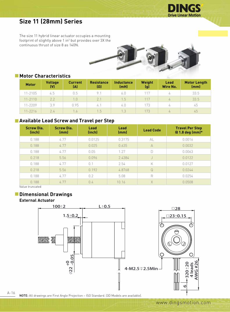
The size 11 hybrid linear actuator occupies a mounting footprint of slightly above 1 in2 but provides over 3X the continuous thrust of size 8 as 140N.
External Actuator
noTE: All drawings are First Angle Projection – ISO Standard. (3D Models are available).
REVISION
REV. DATE DESCRIPTION DRAWN BY
D
E
F
C C
D
Linear Actuator
常州市鼎智机电有限公司DINGS' MOTION
MFG'D 工艺
TITLE:
DATE 日期 线性步进电机
技术规格书SpecificationUNLESS OTHERWISE SPECIFIED:
其余未注事项:
尺寸单位为毫米(mm).
未注公差按以下标准:
毫米 mm英寸 inch
客户 Customer
Checkd 审核
Name 姓名
APPV'D 批准QA 质量
DRAWN 设计
角度 ±1°
视图 重要尺寸 ▲
何超
L 0.5
1.5 0.2
100 2
32020
4 leads
AWG #26
4-M2.5 2.5Min
6
23 0.15
28
19.1
3- 3.2
12.7
9.5
8
220 0.05
3.2
Size 11 (28mm) Series
Screw Dia.(inch)
Screw Dia.(mm)
Lead(inch)
Lead (mm) Lead Code Travel Per Step
@ 1.8 deg (mm)*
0.188 4.77 0.0125 0.3175 AL 0.0016
0.188 4.77 0.025 0.635 A 0.0032
0.188 4.77 0.05 1.27 D 0.0063
0.218 5.56 0.096 2.4384 J 0.0122
0.188 4.77 0.1 2.54 K 0.0127
0.218 5.56 0.192 4.8768 Q 0.0244
0.188 4.77 0.2 5.08 R 0.0254
0.188 4.77 0.4 10.16 X 0.0508
Dimensional Drawings
Value truncated
Motor Voltage(V)
Current(A)
Resistance (Ω)
Inductance (mH)
Weight(g)
Lead Wire No.
Motor Length (mm)
11-2105 4.5 0.5 9.1 6.0 117 4 33.5
11-2110 2.2 1.0 2.1 1.5 117 4 33.5
11-2209 3.9 0.95 4.1 4.0 173 4 45
11-2216 2.4 1.6 1.5 1.3 173 4 45

www.dingsmotion.com
A-17
Non-Captive Actuator
noTE: All drawings are First Angle Projection – ISO Standard. (3D Models are available).
REVISIONREV. DATE DESCRIPTION DRAWN BY
D
E
F
C C
D
Linear Actuator
常州市鼎智机电有限公司
DINGS' MOTION
MFG'D 工艺
TITLE:
DATE 日期 线性步进电机
技术规格书
SpecificationUNLESS OTHERWISE SPECIFIED:其余未注事项:尺寸单位为毫米(mm). 未注公差按以下标准:
毫米 mm英寸 inch
客户 Customer
Checkd 审核
Name 姓名
APPV'D 批准QA 质量
DRAWN 设计角度 ±1°
视图 重要尺寸▲
何超
L 0.5
1.5 0.2
100 1
32020
4 leads
AWG 26#
4-M2.5 2.5Min
6
23 0.15
28
6
M3x0.5
220 0.05
Size 11 (28mm) Series
11E2034X4-100-012MS MOTOR
DATE REV03
LABEL
Grn
/Wht
B-
Grn
B+
Red/Wht A-
Red A+
M
LEAD WIRE CONFIGURATIONWinding excited sequence电机通电运转
-
CW 正转
A+
A-
B+
B-
CCW 反转
+
-
-
+
-
+
+
182 1
3
- -0.02
0.05
3.5
33.5 0.5
1.65 0.2
22
-0 0.05
12
4
-0 0.03
320
204
lead
sA
WG
#26 4-M2.5 2.5
23 0.15
28.2
19.05
3- 3.2
12.7
8
3.2
9.5
TECHNICAL PARAMETERS
REVISION
REV. DATE DESCRIPTION DRAWN BY
01 2013/09/05 182 was 161.5
02 2013/09/10 182±1 was 182±2
03 2015/01/09 added the shaft
D
E
F
C
1 2 3 4
B
A
321 5
C
D
4 6 7 8
A
B
Linear Actuator
11E2034X4-100-012
MS MOTOR
MFG'D 工艺A3
SHEET 1 OF 1SCALE:
DWG NO.
TITLE:
DATE 日期 线性步进电机
技术规格书Specification
2013.05.17
UNLESS OTHERWISE SPECIFIED:其余未注事项:DIMENSIONS ARE IN MILLIMETERS尺寸单位为毫米(mm). TOLERANCES AS BELOW:未注公差按以下标准:
毫米 mm英寸 inch
客户 Customer
Checkd 审核
Name 姓名
APPV'D 批准QA 质量
DRAWN 设计
ANGLE ±1° 角度 ±1°
.X ±0.04 X. ±1.XX ±0.01
.XXX ±0.005.XXXX ±0.0005
.X ±0.25.XX ±0.13
.XXX ±0.013
视图 重要尺寸 ▲
何超
nut Dimensions

www.dingsmotion.com
A-18
Kaptive Actuator
Stroke Specification
Stroke B (mm)
A (mm)
C (mm)
L=33.3 L=45
0.50 (12.70) 15.70 1.0 0.0
0.75 (19.05) 22.10 7.4 0.0
1.00 (25.40) 28.40 13.7 4.0
1.25 (31.80) 34.80 20.1 10.4
1.50 (38.10) 41.10 26.4 16.8
2.00 (50.80) 53.80 39.0 29.4
2.50 (63.50) 66.50 52.7 42.1
尺寸A
22.1 11
D
E
F
C C
D
28固定轴电机
常州市鼎智机电有限公司
DINGS' MOTION
MFG'D 工艺
TITLE:
DATE 日期
UNLESS OTHERWISE SPECIFIED:其余未注事项:尺寸单位为毫米(mm). 未注公差按以下标准:
毫米 mm英寸 inch
客户 Customer
Checkd 审核
Name 姓名
APPV'D 批准QA 质量
DRAWN 设计角度 ±1°
视图 重要尺寸▲
28
234- 0.15
4-M2.5 2.5min
320
204
lead
sAW
G#
26
6
L 0.5
1.3 0.2
A 1 C
13.8
22- 0
.05
0+
1
M3x0.5
5
B
4.77
18
Size 11 (28mm) Series
noTE: All drawings are First Angle Projection – ISO Standard. (3D Models are available).

www.dingsmotion.com
A-19
Size 11 (28mm) Performance Curves
X(mm/s)R(mm/s)Q(mm/s)K(mm/s)J(mm/s)D(mm/s)A(mm/s)AL(mm/s)RPM r/minPPS
10.25.14.92.52.41.30.60.360200
30.515.214.67.67.33.81.91.0180600
50.825.424.412.712.26.33.21.63001000
76.238.136.619.118.39.54.82.44501500
101.650.848.825.424.412.76.43.26002000
152.476.273.238.136.619.19.54.89003000
12763.561.031.830.515.97.94.07502500
Bipolar, Chopper Driver, 1.0 A RMS
Size 11 (28mm) Double Stack Speed Thrust Curves(RECOMMENDED LOAD LIMIT 140N)
0
8.8
4.4
17.6
13.2
22
26.4
39.6
35.2
30.8
180
160
140
120
100
80
60
40
20
0
0.635(A) 0.3175(AL)
1.27(D)
2.54(K)
2.4384(J)
4.8768(Q)
5.08(R)
10.16(X)
Recommended load limit
Bipolar, Chopper Driver, 1.0 A RMS
Size 11 (28mm) Single Stack Speed Thrust Curves(RECOMMENDED LOAD LIMIT 115N)
0
20
40
60
80
120
100
0
4.4
8.8
13.2
17.6
26.4
22
0.635(A)
1.27(D)
0.3175(AL)
5.08(R)4.8768(Q)10.16(X)
2.54(K)2.4384(J)
X(mm/s)R(mm/s)Q(mm/s)K(mm/s)J(mm/s)D(mm/s)A(mm/s)AL(mm/s)RPM r/minPPS
10.25.14.92.52.41.30.60.360200
30.515.214.67.67.33.81.91.0180600
50.825.424.412.712.26.43.21.63001000
76.238.136.619.118.39.54.82.44501500
101.650.848.825.424.412.76.43.26002000
152.476.273.238.136.619.19.59.59003000
12763.561.031.830.515.97.94.07502500
Recommended load limit
Size 11 (28mm) Series
TEST CONDITION:Testing Voltage: 24Vdc, Driver Model: DS-2422-001 bipolar, chopper driver at rated current (rms). Motor's thrust will be changed with different voltage and driver. 50% thrust margin is recommended.
Forc
e (N
)Fo
rce
(N)
lbs
lbs

www.dingsmotion.com
A-20
The size 14 Hybrid precision linear actuator is the mostly used for linear movement applications, provides up to 230N of continuous thrust.
Motor Characteristics
Motor Voltage(V)
Current(A)
Resistance (Ω)
Inductance (mH)
Weight(g)
Lead Wire No.
Motor Length (mm)
14-2105 6.6 0.5 13.2 14.0 189 4 33.6
14-2110 3.3 1.0 3.5 3.6 189 4 33.6
14-2115 2.2 1.5 1.8 1.9 189 4 33.6
14-2205 12.0 0.5 24.0 29.0 210 4 45.6
14-2210 6.0 1.0 6.0 7.2 210 4 45.6
14-2215 4.0 1.5 2.7 3.2 210 4 45.6
Available Lead Screw and Travel per StepScrew Dia.
(inch)Screw Dia.
(mm)Lead(inch)
Lead (mm) Lead Code Travel Per Step
@ 1.8 deg (mm)*Travel Per Step@ 0.9 deg (mm)*
0.25 6.35 0.024 0.6096 AA 0.003 0.0015
0.25 6.35 0.0394 1.0 AB 0.005 0.0025
0.25 6.35 0.048 1.2192 B 0.006 0.003
0.25 6.35 0.05 1.27 D 0.0064 0.0032
0.25 6.35 0.0625 1.5875 F 0.0079 0.004
0.25 6.35 0.096 2.4384 J 0.0122 0.0061
0.25 6.35 0.1 2.54 K 0.0127 0.0064
0.25 6.35 0.125 3.175 L 0.0159 0.0079
0.25 6.35 0.192 4.8768 Q 0.024 0.0122
0.25 6.35 0.25 6.35 S 0.0318 0.0159
0.25 6.35 0.333 8.4582 U 0.0423 0.0211
0.25 6.35 0.3333 8.4667 UA 0.0423 0.0212
0.25 6.35 0.384 9.7536 W 0.0488 0.0244
0.25 6.35 0.5 12.7 Y 0.0635 0.0318
Size 14 (35mm) Series
Value truncated

www.dingsmotion.com
A-21
Non-Captive Actuator
150 2 L 0.5
1.8 0.2
22 -0 0.05
6 32020
4 leads
AWG #26
35
4-M3 4MIN
26 0.2
25.4
3- 3.2
19.05
3.8
12
13.4
REVISIONREV. DATE DESCRIPTION REASONDRAWN BY
D
E
F
C C
D
Linear Actuator
常州市鼎智机电有限公司
DINGS' MOTION
MFG'D 工艺
TITLE:
DATE 日期 线性步进电机
技术规格书
SpecificationUNLESS OTHERWISE SPECIFIED:其余未注事项:尺寸单位为毫米(mm). 未注公差按以下标准:
毫米 mm英寸 inch
客户 Customer
Checkd 审核
Name 姓名
APPV'D 批准QA 质量
DRAWN 设计角度 ±1°
视图 重要尺寸▲
何超
L 0.51.8 0.2
8
150 1
26 0.2
35 32020
4 leads
AWG #26
6
4-M3 4Min
22 -0 0.05
REVISIONREV. DATE DESCRIPTION DRAWN BY
D
E
F
C C
D
Linear Actuator
常州市鼎智机电有限公司
DINGS' MOTION
MFG'D 工艺
TITLE:
DATE 日期 线性步进电机
技术规格书
SpecificationUNLESS OTHERWISE SPECIFIED:其余未注事项:尺寸单位为毫米(mm). 未注公差按以下标准:
毫米 mm英寸 inch
客户 Customer
Checkd 审核
Name 姓名
APPV'D 批准QA 质量
DRAWN 设计角度 ±1°
视图 重要尺寸▲
何超
noTE: All drawings are First Angle Projection – ISO Standard. (3D Models are available).
Size 14 (35mm) Series
External ActuatorDimensional Drawings
nut Dimension

www.dingsmotion.com
A-22
Captive Actuator
Stroke Specification
L 0.5 A 6 6
4 1.5 0.2
10
10 -0 0.03
B
6 32020
4 leads
AWG #26
26 0.2
35
4-M3 THRU
22 -0 0.05
REVISIONREV. DATE DESCRIPTION REASONDRAWN BY
D
E
F
C C
D
Linear Actuator
常州市鼎智机电有限公司
DINGS' MOTION
MFG'D 工艺
TITLE:
DATE 日期 线性步进电机
技术规格书
SpecificationUNLESS OTHERWISE SPECIFIED:其余未注事项:尺寸单位为毫米(mm). 未注公差按以下标准:
毫米 mm英寸 inch
客户 Customer
Checkd 审核
Name 姓名
APPV'D 批准QA 质量
DRAWN 设计角度 ±1°
Standard motor标准电机
视图 重要尺寸▲
何超
Stroke Binch (mm)
A (mm) L (mm)
0.50 (12.70) 35.70
Single Stack Motor
33.6mm
Double Stack Motor
45.6mm
0.75 (19.05) 42.05
1.00 (25.40) 48.40
1.25 (31.80) 54.80
1.50 (38.10) 61.10
2.00 (50.80) 73.80
2.50 (63.50) 86.50
Size 14 (35mm) Series
noTE: All drawings are First Angle Projection – ISO Standard. (3D Models are available).
www.dingsmotion.com
A-23
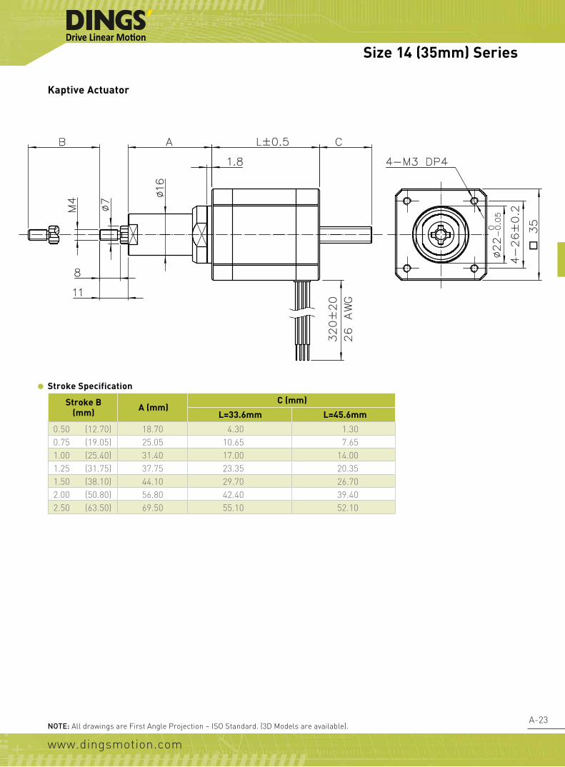
Stroke B (mm) A (mm)
C (mm)
L=33.6mm L=45.6mm
0.50 (12.70) 18.70 4.30 1.300.75 (19.05) 25.05 10.65 7.651.00 (25.40) 31.40 17.00 14.001.25 (31.75) 37.75 23.35 20.351.50 (38.10) 44.10 29.70 26.702.00 (50.80) 56.80 42.40 39.402.50 (63.50) 69.50 55.10 52.10
Kaptive Actuator
Stroke Specification
Size 14 (35mm) Series
noTE: All drawings are First Angle Projection – ISO Standard. (3D Models are available).

www.dingsmotion.com
A-24
Size 14 (35mm) Performance Curves
Bipolar, Chopper Driver, 1.0 A RMS
Size 14 (35mm) Single Stack Speed Thrust Curves(RECOMMENDED LOAD LIMIT 230N)
350
300
250
200
150
100
50
0
77
66
55
44
33
22
11
0
0.6096 (AA)
1.0 (AB)1.2192 (B)
1.27 (D)
1.5875 (F)
2.4384 (J)
J(mm/s)F(mm/s)D(mm/s)B(mm/s)AB(mm/s)AA(mm/s)RPM r/minPPS
2.41.61.31.21.00.660200
7.34.83.83.73.01.8180600
9.86.45.14.94.02.4240800
12.27.96.46.15.03.03001000
18.311.99.59.17.54.64501500
24.415.912.712.210.06.16002000
30.519.815.915.212.57.67502500
Recommended load limit
Bipolar, Chopper Driver, 1.0 A RMS
Size 14 (35mm) Single Stack Speed Thrust Curves(RECOMMENDED LOAD LIMIT 230N)
Y(mm/s)W(mm/s)U(mm/s)UA(mm/s)S(mm/s)Q(mm/s)L(mm/s)K(mm/s)RPM r/minPPS
12.79.88.58.46.34.93.22.560200
38.129.325.425.119.114.69.57.6180600
50.839.025.433.525.419.512.710.2180.3601
63.548.842.341.931.824.415.912.73001000
95.373.263.562.947.636.623.819.14501500
127.097.584.783.863.548.831.825.46002000
158.8121.9105.8104.879.461.039.731.87502500
180
160
140
120
100
80
60
40
20
0
39.6
35.2
30.8
26.4
22.0
17.6
13.2
8.8
4.4
0
3.175(L)
4.8768(Q)
6.35(S)
8.4582(U)/8.4667(UA)9.7536(W)
12.7(Y)
2.54(K)
Size 14 (35mm) Series
TEST CONDITION:Testing Voltage: 24Vdc, Driver Model: DS-2422-001 bipolar, chopper driver at rated current (rms). Motor's thrust will be changed with different voltage and driver. 50% thrust margin is recommended.
Forc
e (N
)Fo
rce
(N)
lbs
lbs

www.dingsmotion.com
A-25
Bipolar, Chopper Driver, 1.5 A RMS
Size 14 (35mm) Double Stack Speed Thrust Curves
Y(mm/s)W(mm/s)U(mm/s)UA(mm/s)S(mm/s)Q(mm/s)L(mm/s)K(mm/s)RPM r/minPPS
12.79.88.58.46.34.93.22.560200
38.129.325.425.119.114.69.57.6180600
50.839.025.433.525.419.512.710.2180.3601
63.548.842.341.931.824.415.912.73001000
95.373.263.562.947.636.623.819.14501500
127.097.584.783.863.548.831.825.46002000
158.8121.9105.8104.879.461.039.731.87502500
180
160
140
120
100
80
60
40
20
0
39.6
35.2
30.8
26.4
22.0
17.6
13.2
8.8
4.4
0
3.175(L)
4.8768(Q)
6.35(S)
8.4582(U)/8.4667(UA)9.7536(W)
12.7(Y)
2.54(K)
(RECOMMENDED LOAD LIMIT 230N)
Bipolar, Chopper Driver, 1.5 A RMS
Size 14 (35mm) Double Stack Speed Thrust Curves(RECOMMENDED LOAD LIMIT 230N)
350
300
250
200
150
100
50
0
77
66
55
44
33
22
11
0
0.6096 (AA)
1.0 (AB)1.2192 (B)
1.27 (D)
1.5875 (F)
2.4384 (J)
J(mm/s)F(mm/s)D(mm/s)B(mm/s)AB(mm/s)AA(mm/s)RPM r/minPPS
2.41.61.31.21.00.660200
7.34.83.83.73.01.8180600
9.86.45.14.94.02.4240800
12.27.96.46.15.03.03001000
18.311.99.59.17.54.64501500
24.415.912.712.210.06.16002000
30.519.815.915.212.57.67502500
Recommended load limit
Size 14 (35mm) Series
TEST CONDITION:Testing Voltage: 24Vdc, Driver Model: DS-2422-001 bipolar, chopper driver at rated current (rms). Motor's thrust will be changed with different voltage and driver. 50% thrust margin is recommended.
Forc
e (N
)Fo
rce
(N)
lbs
lbs

www.dingsmotion.com
A-26
Screw Dia.(inch)
Screw Dia.(mm)
Lead(inch)
Lead (mm)
Lead Code
Travel Per Step@ 1.8 deg (mm)*
Travel Per Step@ 0.9 deg (mm)*
0.25 6.35 0.024 0.6096 AA 0.003 0.00150.25 6.35 0.0394 1.0 AB 0.005 0.0025
0.25 6.35 0.048 1.2192 B 0.006 0.003 0.25 6.35 0.05 1.27 D 0.0064 0.0032 0.25 6.35 0.063 1.5875 F 0.0079 0.004
0.31 8.00 0.083 2.1167 H 0.0106 0.0053 0.25 6.35 0.096 2.4384 J 0.0122 0.0061 0.25 6.35 0.1 2.54 K 0.0127 0.0064
0.25 6.35 0.125 3.175 L 0.0159 0.00790.25 6.35 0.192 4.8768 Q 0.024 0.0122
0.25 6.35 0.25 6.35 S 0.0318 0.01590.25 6.35 0.333 8.4582 U 0.0423 0.0211
0.25 6.35 0.3333 8.4667 UA 0.0423 0.0212 0.25 6.35 0.384 9.7536 W 0.0488 0.0244 0.25 6.35 0.5 12.7 Y 0.0635 0.0318 0.31 8.00 0.1575 4.0 M* 0.02 0.01 0.31 8.00 0.315 8.0 T* 0.04 0.02 0.31 8.00 0.0787 2.0 G* 0.01 0.005
Motor Voltage(V)
Current(A)
Resistance (Ω)
Inductance (mH)
Weight(g)
Lead Wire No.
Motor Length (mm)
17-2105 7.2 0.5 14.4 19.8 254 4 34.117-2110 3.6 1.0 3.6 5.0 254 4 34.117-2115 2.4 1.5 1.9 2.2 254 4 34.117-2205 11.0 0.5 22.0 46.0 386 4 48.117-2212 4.5 1.2 3.8 8.0 386 4 48.117-2225 2.2 2.5 0.9 1.8 386 4 48.1
The size 17 Hybrid precision linear actuator is the mostly used for linear movement applications, provides up to 330N of continuous thrust.
Available Lead Screw and Travel per Step
Motor Characteristics
Value truncated*these three leads can not be appllied in structure of Non-captive and Kaptive, and all kinds of anti-backlash nut
Size 17 (42mm) Series

www.dingsmotion.com
A-27
1.8 0.2
L 0.5
22 -0 0.05
150 2
31 0.2
42.2
4-M3 4min
32020
4 leads
AWG#26
6
25.4
3- 3.2
19.05
3.8
12
13.4
REVISIONREV. DATE DESCRIPTION DRAWN BY
D
E
F
C C
D
Linear Actuator
常州市鼎智机电有限公司
DINGS' MOTION
MFG'D 工艺
TITLE:
DATE 日期 线性步进电机
技术规格书
SpecificationUNLESS OTHERWISE SPECIFIED:其余未注事项:尺寸单位为毫米(mm). 未注公差按以下标准:
毫米 mm英寸 inch
客户 Customer
Checkd 审核
Name 姓名
APPV'D 批准QA 质量
DRAWN 设计角度 ±1°
视图 重要尺寸▲
何超
31 0.2
42.2
4-M3 4min
32020
4 leads
AWG#26
22 -0 0.05
6
L 0.5 1.8 0.2
150 1
8
REVISIONREV. DATE DESCRIPTION REASONDRAWN BY
D
E
F
C C
D
Linear Actuator
常州市鼎智机电有限公司
DINGS' MOTION
MFG'D 工艺
TITLE:
DATE 日期 线性步进电机
技术规格书
SpecificationUNLESS OTHERWISE SPECIFIED:其余未注事项:尺寸单位为毫米(mm). 未注公差按以下标准:
毫米 mm英寸 inch
客户 Customer
Checkd 审核
Name 姓名
APPV'D 批准QA 质量
DRAWN 设计角度 ±1°
视图 重要尺寸▲
何超
noTE: All drawings are First Angle Projection – ISO Standard. (3D Models are available).
Size 17 (42mm) Series
Non-Captive Actuator
External ActuatorDimensional Drawings
nut Dimension

www.dingsmotion.com
A-28
6 A 6
4 1.5 0.2
10
10 -0 0.03
L 0.5
B 31 0.2
42.2
32020
4 leads
AWG #26
22 -0 0.05
6 4-M3 THRU
REVISIONREV. DATE DESCRIPTION REASONDRAWN BY
D
E
F
C C
D
Linear Actuator
常州市鼎智机电有限公司
DINGS' MOTION
MFG'D 工艺
TITLE:
DATE 日期 线性步进电机
技术规格书
SpecificationUNLESS OTHERWISE SPECIFIED:其余未注事项:尺寸单位为毫米(mm). 未注公差按以下标准:
毫米 mm英寸 inch
客户 Customer
Checkd 审核
Name 姓名
APPV'D 批准QA 质量
DRAWN 设计角度 ±1°
standard motor标准电机
视图 重要尺寸▲
何超
Captive Actuator
Stroke Specification
Stroke Binch (mm)
A (mm) L (mm)
0.50 (12.70) 35.70
Single Stack Motor
34.1mm
Double Stack Motor
48.1mm
0.75 (19.05) 42.05
1.00 (25.40) 48.40
1.25 (31.80) 54.80
1.50 (38.10) 61.10
2.00 (50.80) 73.80
2.50 (63.50) 86.50
Size 17 (42mm) Series
noTE: All drawings are First Angle Projection – ISO Standard. (3D Models are available).

www.dingsmotion.com
A-29
Stroke B (mm) A (mm)C (mm)
Single StackMotor L=34.1 (mm)
Double StackMotor L=48.1 (mm)
0.50 (12.70) 18.50 4.10 0.000.75 (19.05) 24.85 10.45 5.451.00 (25.40) 31.20 16.80 11.801.25 (31.75) 37.55 23.15 18.151.50 (38.10) 43.90 29.50 24.502.00 (50.80) 56.60 42.20 37.202.50 (63.50) 69.30 54.90 49.90
Kaptive Actuator
Stroke Specification
Size 17 (42mm) Series
noTE: All drawings are First Angle Projection – ISO Standard. (3D Models are available).

www.dingsmotion.com
A-30
Size 17 (42mm) Performance Curves
Bipolar, Chopper Driver, 1.0 A RMSSize 17 (42mm) Single Stack Speed Thrust Curves
450
400
350
300
250
200
150
100
99
88
77
66
55
44
33
22J(mm/s)H(mm/s)G(mm/s)F(mm/s)D(mm/s)B(mm/s)AB(mm/s)AA(mm/s)RPM r/minPPS
2.42.12.01.61.31.21.00.660200
7.36.46.04.83.83.73.01.8180600
9.88.58.06.45.14.94.02.4240800
12.210.610.07.96.46.15.03.03001000
18.315.915.011.99.59.17.54.64501500
24.421.220.015.912.712.210.06.16002000
30.526.525.019.815.915.2412.57.67502500
1.0 (AB)0.6096 (AA)
1.2192 (B)1.27 (D)
1.5875 (F)
2.4384(J)2.1167(H)
2.0(G)
(RECOMMENDED LOAD LIMIT 230N)
Recommended load limit
Size 17 (42mm) Single Stack Speed Thrust Curves
Y (mm/s)W (mm/s)UA (mm/s)U (mm/s)T (mm/s)S (mm/s)Q (mm/s)M (mm/s)L (mm/s)K (mm/s)RPM r/minPPS
12.79.88.58.48.06.44.94.03.22.560200
38.129.325.425.124.019.114.612.09.57.6180600
50.839.033.933.532.025.419.516.012.710.2240800
63.548.842.341.940.031.824.420.015.912.73001000
95.373.263.460.047.636.630.023.819.14501500
12797.584.783.880.063.548.840.031.825.46002000
158.8121.9105.8104.8100.079.461.050.039.731.87502500
250
200
150
100
50
0
55
44
33
22
11
0
3.175(L)
4.8768(Q)
6.35(S)
9.7536(W)12.7(Y)
2.54(K)
4.0(M)
8.0(T)
Bipolar, Chopper Driver, 1.0 A RMS (RECOMMENDED LOAD LIMIT 230N)
Recommended load limit
8.4582(U)8.4667(UA)
Size 17 (42mm) Series
TEST CONDITION:Testing Voltage: 24Vdc, Driver Model: DS-2422-001 bipolar, chopper driver at rated current (rms). Motor's thrust will be changed with different voltage and driver. 50% thrust margin is recommended.
Forc
e (N
)Fo
rce
(N)
lbs
lbs

www.dingsmotion.com
A-31
650
600
550
500
450
400
350
300
250
200
143
132
121
110
99
88
77
66
55
44
Size 17 (42mm) Double Stack Speed Thrust Curve
J(mm/s)H(mm/s)G(mm/s)F(mm/s)D(mm/s)B(mm/s)AB(mm/s)AA(mm/s)RPM r/minPPS
2.42.12.01.61.31.21.00.660200
7.36.46.04.83.83.73.01.8180600
9.88.58.06.45.14.94.02.4240800
12.210.610.07.96.46.15.03.03001000
18.315.915.011.99.59.17.54.64501500
24.421.220.015.912.712.210.06.16002000
30.526.525.019.815.915.212.57.67502500
2.4384(J)2.1167(H)
1.0 (AB) 0.6096 (AA)
1.2192(B)
1.27(D)
1.5875(F)
Bipolar, Chopper Driver, 2.5 A RMS (RECOMMENDED LOAD LIMIT 230N)
Recommended load limit 2.0(G)
Y (mm/s)W (mm/s)UA (mm/s)U (mm/s)T (mm/s)S (mm/s)Q (mm/s)M (mm/s)L (mm/s)K (mm/s)RPM r/minPPS
12.79.88.58.48.06.44.94.03.22.560200
38.129.325.425.124.019.114.612.09.57.6180600
50.839.033.933.532.025.419.516.012.710.2240800
63.548.842.341.940.031.824.420.015.912.73001000
95.373.263.562.960.047.636.630.023.819.14501500
127.097.584.783.880.063.548.840.031.825.46002000
158.8121.9105.8104.8100.079.461.050.039.731.87502500
350
300
250
200
150
100
50
0
77
66
55
44
33
22
11
0
Size 17 (42mm) Double Stack Speed Thrust Curve
2.54(K)
3.175(L)
8.4582(U)/8.4667(U)9.7536(W)
12.7(Y)
6.35(S)
4.8768(Q)4.0 (M)
8.0 (T)
Bipolar, Chopper Driver, 2.5 A RMS (RECOMMENDED LOAD LIMIT 230N)
Recommended load limit
Size 17 (42mm) Series
TEST CondiTion:Testing Voltage: 24Vdc, Driver Model: DS-2422-001 bipolar, chopper driver at rated current (rms). Motor's thrust will be changed with different voltage and driver. 50% thrust margin is recommended.
Forc
e (N
)Fo
rce
(N)
lbs
lbs

www.dingsmotion.com
A-32
Screw Dia.(inch)
Screw Dia.(mm)
Lead(inch)
Lead (mm) Lead Code Travel Per Step
@ 1.8 deg (mm)*Travel Per Step@ 0.9 deg (mm)*
0.315 10.000 0.079 2.0 G 0.01 0.005
0.375 9.525 0.025 0.635 A 0.0032 0.0016
0.375 9.525 0.05 1.27 D 0.0064 0.0032
0.375 9.525 0.0625 1.5875 F 0.0079 0.004
0.375 9.525 0.083 2.1167 H 0.0106 0.0053
0.375 9.525 0.1 2.54 K 0.0127 0.0064
0.375 9.525 0.125 3.175 L 0.0159 0.0079
0.375 9.525 0.167 4.2333 P 0.0212 0.0106 0.375 9.525 0.2 5.08 R 0.0254 0.0127 0.375 9.525 0.25 6.35 S 0.0318 0.0159
0.375 9.525 0.375 9.525 V 0.0476 0.0238
0.375 9.525 0.384 9.7536 W 0.0488 0.0244
0.375 9.525 0.4 10.16 X 0.0508 0.0254
0.375 9.525 0.5 12.7 Y 0.0635 0.0318
0.375 9.525 1.0 25.4 Z 0.127 0.0635
The size 23 hybrid precision linear actuator is with high performance and longer working cycle, which could be applied with high request of force, it is capable of 910N.
Available Lead Screw and Travel per Step
Motor Characteristics
Size 23 (57mm) Series
Motor Voltage(V)
Current(A)
Resistance (Ω)
Inductance (mH)
Weight(g)
Lead Wire No.
Motor Length (mm)
23-2110 6.4 1.0 6.4 16.4 585 4 4523-2120 3.2 2.0 1.75 4.1 585 4 4523-2130 2.1 3.0 0.8 1.7 585 4 4523-2210 10.8 1.0 11.5 32.0 880 4 6523-2225 4.2 2.5 2.0 5.2 880 4 6523-2240 2.4 4.0 0.7 2.0 880 4 65
Value truncated

www.dingsmotion.com
A-33
•
•
•
• •
•
• • • •• • •••••••••
• • • • • • • • • • • • • • • • • • • • • •
• • • •• •• • • • • • •
• • • •• • • • • • • •
• • • • • •
• • ••••••• • • • • • • • • • • • •
• • • • • • • • • •
• • ••• •• • • • • • •• • • •• • • • •• • • • ••••••••••••••• • • • • • • • • • • • • •• • • • • • • • • ••••••••••••• • • • • • • • • • • • • • • • • • • •
• • •• • • •• • •• • • • • •
• • •• •• •••••••
• • • ••••••••
• • •••••••
• • •••••••••• ••••• • • • • • • • •
• • • • • • • • • •• • ••• • • • • •
• • • • • • • • • • • •• •
• • • •
Size 23 (57mm) Series
Non-Captive Actuator
External ActuatorDimensional Drawings
noTE: All drawings are First Angle Projection – ISO Standard. (3D Models are available).
nut Dimension
www.dingsmotion.com
A-34
Captive Actuator
A 6
12
15
4 1.5 0.2
6 L 0.6
5 15 -0 0.03
B 47.14 0.25 56.2
4-M4 THRU
38.10 -0 0.05
32020
4 leads
AWG #22
REVISIONREV. DATE DESCRIPTION DRAWN BY
D
E
F
C C
D
Linear Actuator
常州市鼎智机电有限公司
DINGS' MOTION
MFG'D 工艺
TITLE:
DATE 日期 线性步进电机
技术规格书
SpecificationUNLESS OTHERWISE SPECIFIED:其余未注事项:尺寸单位为毫米(mm). 未注公差按以下标准:
毫米 mm英寸 inch
客户 Customer
Checkd 审核
Name 姓名
APPV'D 批准QA 质量
DRAWN 设计角度 ±1°
标准电机Standard motor
视图 重要尺寸▲
何超
Stroke Specification
Stroke Binch (mm)
A (mm) L (mm)
0.50 (12.70) 45.70
Single Stack Motor45mm
Double Stack Motor65mm
0.75 (19.05) 52.05
1.00 (25.40) 58.40
1.25 (31.80) 64.80
1.50 (38.10) 71.10
2.00 (50.80) 83.80
2.50 (63.50) 96.50
Size 23 (57mm) Series
noTE: All drawings are First Angle Projection – ISO Standard. (3D Models are available).

www.dingsmotion.com
A-35
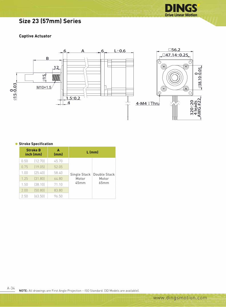
Stroke Specification
M6 9.5
B A L C
1215
1.5
28
32020
22 AWG
5.24-
38.1 -0 0.05
4-47.140.2
56.2
Stroke B (mm) A (mm)C (mm)
L=45 (mm) L=65 (mm)
0.50 (12.70) 24.20 5.80 0.000.75 (19.05) 30.55 12.15 2.151.00 (25.40) 36.90 18.50 8.501.25 (31.75) 43.25 24.85 14.851.50 (38.10) 49.60 31.20 21.202.00 (50.80) 62.30 43.90 33.902.50 (63.50) 75.00 56.60 46.60
Kaptive Actuator
Size 23 (57mm) Series

www.dingsmotion.com
A-36
Size 23 (57mm) Performance Curves
P(mm/s)L(mm/s)K(mm/s)H(mm/s)G(mm/s)F(mm/s)D(mm/s)A(mm/s)RPM r/minPPS
4.23.22.52.12.01.61.30.660200
12.79.57.66.46.04.83.81.8180600
21.215.912.710.610.07.96.43.03001000
31.723.819.115.915.011.99.54.64501500
42.331.825.421.220.015.912.76.16002000
63.547.638.131.830.023.819.19.19003000
53.039.731.826.525.019.815.97.67502500
22
176
154
132
110
88
66
44
Bipolar, Chopper Driver, 2.0 A RMSSize 23 (57mm) Single Stack Speed Thrust Curves
(RECOMMENDED LOAD LIMIT 910N)
100
200
300
400
500
600
800
7000.635(A)
1.27(D)1.5875(F)
2.1167(H)
2.54(K)
3.175(L) 2.0(G)
4.2333(P)
Z(mm/s)Y(mm/s)X(mm/s)W(mm/s)V(mm/s)S(mm/s)R(mm/s)RPM r/minPPS
25.412.710.29.89.56.45.160200
76.238.130.529.328.619.115.2180600
127.063.550.848.847.631.825.43001000
190.595.376.273.271.447.638.14501500
254.0127.0101.697.595.363.550.86002000
381.0190.5152.4146.3142.995.376.29003000
317.5158.8127.0121.9119.179.463.57502500
0
11
77
66
55
44
33
22
Size 23 (57mm) Single Stack Speed Thrust Curves
0
50
100
150
200
250
300
3505.08(R)
9.525(V)
9.7536(W)10.16(X)
25.4(Z)
12.7(Y)
6.35(S)
Bipolar, Chopper Driver, 2.0 A RMS (RECOMMENDED LOAD LIMIT 910N)
Size 23 (57mm) Series
TEST CONDITION:Testing Voltage: 40Vdc, Driver Model: DS-5045-003 bipolar, chopper driver at rated current (rms). Motor's thrust will be changed with different voltage and driver. 50% thrust margin is recommended.
Forc
e (N
)Fo
rce
(N)
lbs
lbs

www.dingsmotion.com
A-37
0
44
308
264
220
176
132
88
Size 23 (57mm) Double Stack Speed Thrust Curves
0
400
200
600
800
1200
1000
1400
P(mm/s)L(mm/s)K(mm/s)H(mm/s)G(mm/s)F(mm/s)D(mm/s)A(mm/s)RPM r/minPPS
4.23.22.52.12.01.61.30.660200
12.79.57.66.46.04.83.81.8180600
21.215.912.710.610.07.96.43.03001000
31.823.819.115.915.011.99.54.64501500
42.431.825.421.220.015.912.76.16002000
63.547.638.131.830.023.819.19.19003000
53.039.731.826.525.019.815.97.67502500
0.635(A)1.5875(F)
2.1167(H)
3.175(L)2.0(G)
2.54(K)
4.2418(P)
1.27(D)
Bipolar, Chopper Driver, 4.0 A RMS (RECOMMENDED LOAD LIMIT 910N)
Recommended load limit
0
22
132
110
88
66
44
Size 23 (57mm) Double Stack Speed Thrust Curves
0
100
200
300
400
500
600
Z(mm/s)Y(mm/s)X(mm/s)W(mm/s)V(mm/s)S(mm/s)R(mm/s)RPM r/minPPS
25.412.710.29.89.56.45.160200
76.238.130.529.328.619.115.2180600
127.063.550.848.847.631.825.43001000
190.595.376.273.271.447.638.14501500
254.0127.0101.697.595.363.550.86002000
381.0190.5152.4146.3142.995.376.29003000
317.5158.8127.0121.9119.179.463.57502500
5.08(R)
9.525(V)
9.7536(W)
12.7(Y)10.16(X)
6.35(S)
25.4(Z)
Bipolar, Chopper Driver, 4.0 A RMS (RECOMMENDED LOAD LIMIT 910N)
Size 23 (57mm) Series
TEST CONDITION:Testing Voltage: 40Vdc, Driver Model: DS-5045-003 bipolar, chopper driver at rated current (rms). Motor's thrust will be changed with different voltage and driver. 50% thrust margin is recommended.
Forc
e (N
)Fo
rce
(N)
lbs
lbs

www.dingsmotion.com
A-38
Screw Dia.(inch)
Screw Dia.(mm)
Lead(inch)
Lead (mm) Lead Code Travel Per Step
@ 1.8 deg (mm)*Travel Per Step@ 0.9 deg (mm)*
0.315 10.000 0.079 2.0 G 0.01 0.005
0.375 9.525 0.025 0.635 A 0.0032 0.0016
0.375 9.525 0.05 1.27 D 0.0064 0.0032
0.375 9.525 0.0625 1.5875 F 0.0079 0.004
0.375 9.525 0.083 2.1167 H 0.0106 0.0053
0.375 9.525 0.1 2.54 K 0.0127 0.0064
0.375 9.525 0.125 3.175 L 0.0159 0.0079
0.375 9.525 0.167 4.2333 P 0.0212 0.0106 0.375 9.525 0.2 5.08 R 0.0254 0.0127 0.375 9.525 0.25 6.35 S 0.0318 0.0159
0.375 9.525 0.375 9.525 V 0.0476 0.0238
0.375 9.525 0.384 9.7536 W 0.0488 0.0244
0.375 9.525 0.4 10.16 X 0.0508 0.0254
0.375 9.525 0.5 12.7 Y 0.0635 0.0318
0.375 9.525 1.0 25.4 Z 0.127 0.0635
The size 24 hybrid precision linear actuator is with high performance and longer working cycle, which could be applied with high request of force, it is capable of 1050N.
Available Lead Screw and Travel per Step
Motor Characteristics
Size 24 (60mm) Series
Motor Voltage(V)
Current(A)
Resistance (Ω)
Inductance (mH)
Weight(g)
Lead Wire No.
Motor Length (mm)
24-2120 3.0 2 1.5 3.9 680 4 4724-2130 1.8 3 0.6 1.6 680 4 4724-2140 1.6 4 0.4 0.9 680 4 4724-2230 3.0 3 1.0 3.4 1080 4 68.324-2240 2.4 4 0.6 1.9 1080 4 68.324-2250 1.5 5 0.3 1.2 1080 4 68.3
Value truncated

www.dingsmotion.com
A-39
•
•
•
• •
•
• • • •• • •••••••••
• • • • • • • • • • • • • • • • • • • • • •
• • • •• •• • • • • • •
• • • •• • • • • • • •
• • • • • •
••••••••• • • • • • • • • • • • •
• • • • • • • • • •
• • ••• •• • • • • • •• • • •• • • • •• • • • ••••••••••••••• • • • • • • • • • • • • •• • • • • • • • • ••••••••••••• • • • • • • • • • • • • • • • • • • •
• • •• • • •• • •• • • • • •
• • •• •• •••••••
•••••••••••
•••••••••
•••••••••••• ••••• • • • • • • • •
• • • • • • • • • •••••••••••
• • • • • • • • • • • •• •
• • • •
Size 24 (60mm) Series
Non-Captive Actuator
External ActuatorDimensional Drawings
noTE: All drawings are First Angle Projection – ISO Standard. (3D Models are available).
nut Dimension

www.dingsmotion.com
A-40
Captive Actuator
REVISIONREV. DATE DESCRIPTION DRAWN BY
D
E
F
C C
D
Linear Actuator
常州市鼎智机电有限公司
DINGS' MOTION
MFG'D 工艺
TITLE:
DATE 日期 线性步进电机
技术规格书
SpecificationUNLESS OTHERWISE SPECIFIED:其余未注事项:尺寸单位为毫米(mm). 未注公差按以下标准:
毫米 mm英寸 inch
客户 Customer
Checkd 审核
Name 姓名
APPV'D 批准QA 质量
DRAWN 设计角度 ±1°
标准电机Standard motor
视图 重要尺寸▲
何超
47.1 0.25 56.2
38.10 -0 0.05
32020
4 leads
AWG#22
4-M4 thru
60
6
6 A 6 L 1
15
12
4 1.5 0.2
B
M10×1.5
Stroke Specification
Stroke Binch (mm)
A (mm) L (mm)
0.50 (12.70) 45.70
Single Stack Motor47mm
Double Stack Motor
68.3mm
0.75 (19.05) 52.05
1.00 (25.40) 58.40
1.25 (31.80) 64.80
1.50 (38.10) 71.10
2.00 (50.80) 83.80
2.50 (63.50) 96.50
Size 24 (60mm) Series
noTE: All drawings are First Angle Projection – ISO Standard. (3D Models are available).

www.dingsmotion.com
A-41
Stroke Specification
L 0.5 C A
1.7 0.2 28
36 -0 0.05
6.2
9.5
12
15
9.525
B
M6x1
60
50 0.25
4- 5 + 0.30
32020
4 leads
AWG #22
Stroke B (mm) A (mm)C (mm)
L=45 (mm) L=65 (mm)
0.50 (12.70) 24.20 3.30 0.000.75 (19.05) 30.55 9.65 0.001.00 (25.40) 36.90 16.00 3.601.25 (31.75) 43.25 22.35 10.001.50 (38.10) 49.60 28.70 16.302.00 (50.80) 62.30 41.40 29.002.50 (63.50) 75.00 54.00 42.00
Kaptive Actuator
Size 24 (60mm) Series

www.dingsmotion.com
A-42
Size 24 (60mm) Performance Curves
P(mm/s)L(mm/s)K(mm/s)H(mm/s)G(mm/s)F(mm/s)D(mm/s)A(mm/s)RPM r/minPPS
4.23.22.52.12.01.61.30.660200
12.79.57.66.46.04.83.81.8180600
21.215.912.710.610.07.96.43.03001000
31.723.819.115.915.011.99.54.64501500
42.331.825.421.220.015.912.76.16002000
63.547.638.131.830.023.819.19.19003000
53.039.731.826.525.019.815.97.67502500
22
242
220
176
132
198
154
110
88
66
44
Bipolar, Chopper Driver, 2.0 A RMSSize 24 (60mm) Single Stack Speed Thrust Curves
(RECOMMENDED LOAD LIMIT 1050N)
100
400
300
200
500
600
700
800
1100
1000
900
Recommended load limit
0.635(A)
1.27(D)1.5875(F)
2.1167(H)
2.54(K)
3.175(L) 2.0(G)
4.2333(P)
Z(mm/s)Y(mm/s)X(mm/s)W(mm/s)V(mm/s)S(mm/s)R(mm/s)RPM r/minPPS
25.412.710.29.89.56.45.160200
76.238.130.529.328.619.115.2180600
127.063.550.848.847.631.825.43001000
190.595.376.273.271.447.638.14501500
254.0127.0101.697.595.363.550.86002000
381.0190.5152.4146.3142.995.376.29003000
317.5158.8127.0121.9119.179.463.57502500
0
11
99
77
88
66
55
44
33
22
Size 24 (60mm) Single Stack Speed Thrust Curves
0
50
100
150
200
250
300
350
400
4505.08(R)
9.525(V)
9.7536(W)10.16(X)
25.4(Z)
12.7(Y)
6.35(S)
Bipolar, Chopper Driver, 2.0 A RMS (RECOMMENDED LOAD LIMIT 1050N)
Size 24 (60mm) Series
TEST CONDITION:Testing Voltage: 40Vdc, Driver Model: DS-5045-003 bipolar, chopper driver at rated current (rms). Motor's thrust will be changed with different voltage and driver. 50% thrust margin is recommended.
Forc
e (N
)Fo
rce
(N)
lbs
lbs

www.dingsmotion.com
A-43
44
176
132
88
440
396
352
308
264
220
Size 24 (60mm) Double Stack Speed Thrust Curves
400
200
600
800
1200
1000
2000
1600
1400
1800
P(mm/s)L(mm/s)K(mm/s)H(mm/s)G(mm/s)F(mm/s)D(mm/s)A(mm/s)RPM r/minPPS
4.23.22.52.12.01.61.30.660200
12.79.57.66.46.04.83.81.8180600
21.215.912.710.610.07.96.43.03001000
31.823.819.115.915.011.99.54.64501500
42.431.825.421.220.015.912.76.16002000
63.547.638.131.830.023.819.19.19003000
53.039.731.826.525.019.815.97.67502500
0.635(A)1.5875(F)
2.1167(H)
3.175(L)
2.0(G)
2.54(K)
4.2418(P)
1.27(D)
Bipolar, Chopper Driver, 4.0 A RMS (RECOMMENDED LOAD LIMIT 1050N)
Recommended load limit
0
22
176
154
132
110
88
66
44
Size 24 (60mm) Double Stack Speed Thrust Curves
0
100
200
300
400
500
600
700
800
Z(mm/s)Y(mm/s)X(mm/s)W(mm/s)V(mm/s)S(mm/s)R(mm/s)RPM r/minPPS
25.412.710.29.89.56.45.160200
76.238.130.529.328.619.115.2180600
127.063.550.848.847.631.825.43001000
190.595.376.273.271.447.638.14501500
254.0127.0101.697.595.363.550.86002000
381.0190.5152.4146.3142.995.376.29003000
317.5158.8127.0121.9119.179.463.57502500
5.08(R)
9.525(V)
9.7536(W)
12.7(Y)
10.16(X)
6.35(S)
25.4(Z)
Bipolar, Chopper Driver, 4.0 A RMS (RECOMMENDED LOAD LIMIT 1050N)
Size 24 (60mm) Series
TEST CONDITION:Testing Voltage: 40Vdc, Driver Model: DS-5045-003 bipolar, chopper driver at rated current (rms). Motor's thrust will be changed with different voltage and driver. 50% thrust margin is recommended.
Forc
e (N
)Fo
rce
(N)
lbs
lbs

www.dingsmotion.com
A-44
Available Lead Screw and Travel per StepScrew Dia.
(inch)Screw Dia.
(mm)Lead(inch)
Lead (mm) Lead Code Travel Per Step
@ 1.8 deg (mm)*Travel Per Step@ 0.9 deg (mm)*
0.625 15.875 0.1 2.54 K 0.0127 0.0064
0.625 15.875 0.125 3.175 L 0.0159 0.0079
0.625 15.875 0.2 5.08 R 0.0254 0.0127
0.625 15.875 0.25 6.35 S 0.0318 0.0159
0.625 15.875 0.5 12.7 Y 0.0635 0.0318
0.625 15.875 1.0 25.4 Z 0.127 0.0635
Motor CharacteristicsMotor Voltage
(V)Current
(A)Resistance
(Ω)Inductance
(mH)Weight
(g)Lead
Wire No.Motor Length
(mm)
34-2113 12.0 1.3 9.2 71.0 2370 4 76
34-2130 5.7 3.0 1.9 15.0 2370 4 76
34-2155 2.85 5.5 0.52 4.5 2370 4 76
The size 34 hybrid precision linear actuator is in big size, high power, with best performance, which capable of 2270N of continuous thrust.
86 69.3 0.25
32020
4 leads
AWG 20#
6
4- 6.5
76 0.6
1.5 0.2
73 -0 0.05
150 2
57.15
3- 7
44.45
31.7
12.7
28.6
D
E
F
C C
D
常州市鼎智机电有限公司
DINGS' MOTION
MFG'D 工艺
TITLE:
DATE 日期
UNLESS OTHERWISE SPECIFIED:其余未注事项:尺寸单位为毫米(mm). 未注公差按以下标准:
毫米 mm英寸 inch
客户 Customer
Checkd 审核
Name 姓名
APPV'D 批准QA 质量
DRAWN 设计角度 ±1°
视图 重要尺寸▲
李 欢
4- 6.5
Size 34 (86mm) Series
noTE: All drawings are First Angle Projection – ISO Standard. (3D Models are available).
External ActuatorDimensional Drawings
Value truncated

www.dingsmotion.com
A-45
Non-Captive Actuator
86 69.3 0.25
320 20
4 leads
AWG 20#
73 -0 0.05
4- 6.5
76 0.6 1.5 0.2
150 1
15
D
E
F
C C
D
常州市鼎智机电有限公司
DINGS' MOTION
MFG'D 工艺
TITLE:
DATE 日期
UNLESS OTHERWISE SPECIFIED:其余未注事项:尺寸单位为毫米(mm). 未注公差按以下标准:
毫米 mm英寸 inch
客户 Customer
Checkd 审核
Name 姓名
APPV'D 批准QA 质量
DRAWN 设计角度 ±1°
视图 重要尺寸▲
4- 6.5
Size 34 (86mm) Series
noTE: All drawings are First Angle Projection – ISO Standard. (3D Models are available).

www.dingsmotion.com
A-46
Size 34 (86mm) Performance Curves
Z(mm/s)Y(mm/s)S(mm/s)R(mm/s)L(mm/s)K(mm/s)RPM r/minPPS
25.412.76.45.13.22.560200
76.238.119.115.29.57.6180600
101.650.825.420.312.710.2240800
127.063.531.825.415.912.73001000
152.476.238.130.519.115.23601200
190.595.347.638.123.819.14501500
Bipolar, Chopper Driver, 5.5 A RMS
Size 34 (86mm) Single Stack Speed Thrust Curves(RECOMMENDED LOAD LIMIT 2270N)
0
500
1000
1500
2000
2500
0
110
220
330
440
550
2.54(K)3.175(L)
5.08(R)
6.35(S)
12.7(Y)25.4(Z)
Recommended load limit
Size 34 (86mm) Series
TEST CONDITION:Testing Voltage: 40Vdc, Driver Model: DS-2MSD8078-2 bipolar, chopper driver at rated current (rms). Motor's thrust will be changed with different voltage and driver. 50% thrust margin is recommended.
Forc
e (N
)
lbs

www.dingsmotion.com
A-47
Screw End Machining
Threaded End
The screw end machining was
machined depended on screw diameter.
Please contactDINGS’ or your local DINGS’
representative for detailed
screw machining specifications.
Smooth End
None
Customize
Accessories and Options

www.dingsmotion.com
A-48
Size 8 (20mm) and Size 11 (28mm) Size 14 (35mm) and Size 17 (42mm)
Size 23 (57mm)
External Anti-Backlash Nut
Accessories and Options
R10
60°
6
3-2.6
15
16
11
3
2.2
60°
R14 3-
3.2
9 22.22
30
3
4
18
Size 8(20mm)消间隙螺母Size 11(28mm)消间隙螺母
李欢
Size 14(35mm)消间隙螺母
Size 17(42mm)消间隙螺母
Size 23(57mm)消间隙螺母
鼎智消隙螺母
A3图纸 1 (共1)比例:
品号:
姓名材料
批准标准化工艺审核绘制
X.±0.76
日期
.X±0.25.XX±0.13.XXX±0.013
毫米(mm)英寸(inch).X±0.03
.XXXX±0.0005
.XX±0.01.XXX±0.005
角度±1°其余公差执行标准
常州市鼎智机电有限公司
DINGS’ MOTION
品名:
73- 5.1
R19.05
12
28.640
20
R10
60°
6
3-2.6
15
16
11
3
2.2
60°
R14 3-3.2
9 22.22
30
3
4
18
Size 8(20mm)消间隙螺母Size 11(28mm)消间隙螺母
李欢
Size 14(35mm)消间隙螺母
Size 17(42mm)消间隙螺母
Size 23(57mm)消间隙螺母
鼎智消隙螺母
A3图纸 1 (共1)比例:
品号:
姓名材料
批准标准化工艺审核绘制
X.±0.76
日期
.X±0.25.XX±0.13.XXX±0.013
毫米(mm)英寸(inch).X±0.03
.XXXX±0.0005
.XX±0.01.XXX±0.005
角度±1°其余公差执行标准
常州市鼎智机电有限公司
DINGS’ MOTION
品名:
73- 5.1
R19.05
12
28.640
20

www.dingsmotion.com
A-49
Size 14 (35mm) Size 17 (42mm)
Size 11 (28mm)
Non-Captive Anti-Backlash Nut
Customized Nut
Size 8 (20mm)
Anti-Backlash NutAnti-Backlash Nut
Anti-Backlash NutAnti-Backlash Nut
FOR MORE INFOMATION, CONTACT YOUR LOCAL DINGS’REPRESENTATIVE (www.dingsmotion.com)
Accessories and Options
李欢
异形螺母
螺母可定制,更多异形螺母请联系我司技术支持工程师。
异形螺母A3
图纸 1 (共1)比例:
品号:
姓名材料
批准标准化工艺审核绘制
X.±0.76
日期
.X±0.25.XX±0.13
.XXX±0.013
毫米(mm)英寸(inch).X±0.03
.XXXX±0.0005
.XX±0.01.XXX±0.005
角度±1°其余公差执行标准
常州市鼎智机电有限公司DINGS’ MOTION
品名:
李欢
异形螺母
螺母可定制,更多异形螺母请联系我司技术支持工程师。
异形螺母A3
图纸 1 (共1)比例:
品号:
姓名材料
批准标准化工艺审核绘制
X.±0.76
日期
.X±0.25.XX±0.13
.XXX±0.013
毫米(mm)英寸(inch).X±0.03
.XXXX±0.0005
.XX±0.01.XXX±0.005
角度±1°其余公差执行标准
常州市鼎智机电有限公司DINGS’ MOTION
品名:
8
11 1.5 0.2 1.5 0.2
9
12
8
1.8 0.2
10
10
1.8 0.2
7

www.dingsmotion.com
A-50
Encoder
EK2 Encoder – single ended output EK2 Encoder – differential output
EK1 Encoder – differential outputEK1 Encoder – single ended output
0.4711.94
0.51
12.95
0.85
21.63
0.4511.33
0.74
18.89
1.2231.05
1.86
47.14
0.6516.59
1.2231.05
2.04
51.76
0.6516.59
1.11
R28.19
2.84
72.14
0.6516.59
1.11
R28.19
2.99
75.95
0.6516.59
李欢 鼎智编码器A3
图纸 1 (共1)比例:
品号:
姓名
材料
批准标准化工艺审核绘制
X.±0.76
日期
.X±0.25.XX±0.13.XXX±0.013
毫米(mm)英寸(inch).X±0.03
.XXXX±0.0005
.XX±0.01.XXX±0.005
角度±1°
其余公差执行标准
常州市鼎智机电有限公司DINGS’ MOTION
品名:
0.8722
0.
5112
.95
0.5814.61
0.4511.33
0.79 19
.96
李欢
EK1
EK2
EK3
适配20、28、35、42电机
适配35、42、57电机
适配57、86电机
EK1编码器带差分输出
分辨率 100 108 120 125 128 200 250 256 300 360 400 500单端 0 1 2 3 4 5 6 7 8 9 10 11差分 A B C D E F G H I J K L
分辨率 64 100 200 500 1000 1800 2000 2500 3600 4000 5000 7200 8000 10000单端 0 1 2 3 4 5 6 7 8差分 A B C D E F G H I J K L M
分辨率 50 100 192 200 250 256 360 400 500 720 900 1000 1250 2000 2500 4000 5000单端 0 1 2 3 4 5 6 7 8 9 10 11 12差分 A B C D E F G H I J K L M N O P Q
鼎智编码器②A3
图纸 1 (共1)比例:
品号:
姓名材料
批准标准化工艺审核绘制
X.±0.76
日期
.X±0.25.XX±0.13
.XXX±0.013
毫米(mm)英寸(inch).X±0.03
.XXXX±0.0005
.XX±0.01.XXX±0.005
角度±1°其余公差执行标准
常州市鼎智机电有限公司DINGS’ MOTION
品名:
EK2 Encoder (Used for Size 14, 17, 23 Motor)* Index/No index
Resolution(CPR) 50 100 192 200 250 256 360 400 500 720 900 1000 1250 2000 2500 4000 5000
Single ended output 0 1 2 3 4 5 6 7 8 9 10 11 12
Differential output A B C D E F G H I J K L M N O P Q
EK1 Encoder (Used for Size 8, 11, 14, 17 Motor)* No index
Resolution(CPR) 100 108 120 125 128 200 250 256 300 360 400 500
Single ended output 0 1 2 3 4 5 6 7 8 9 10 11
Differential output A B C D E F G H I J K L
Accessories and Options
EK3 Encoder (Used for Size 23, 34 Motor)* Index/No index
Resolution(CPR) 64 100 200 500 1000 1800 2000 2500 3600 4000 5000 7200 8000 10000
Single ended output 0 1 2 3 4 5 6 7 8
Differential output A B C D E F G H I J K L M
EK3 Encoder – single ended output EK3 Encoder – differential output
0.4711.94
0.51
12.95
0.85
21.63
0.4511.33
0.74
18.89
1.2231.05
1.86
47.14
0.6516.59
1.2231.05
2.04
51.76
0.6516.59
1.11
R28.19
2.84
72.14
0.6516.59
1.11
R28.19
2.99
75.95
0.6516.59
李欢 鼎智编码器A3
图纸 1 (共1)比例:
品号:
姓名
材料
批准标准化工艺审核绘制
X.±0.76
日期
.X±0.25.XX±0.13.XXX±0.013
毫米(mm)英寸(inch).X±0.03
.XXXX±0.0005
.XX±0.01.XXX±0.005
角度±1°
其余公差执行标准
常州市鼎智机电有限公司DINGS’ MOTION
品名:
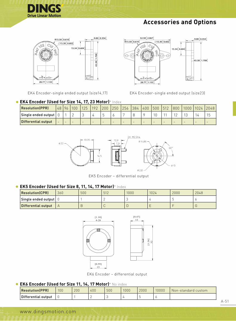
www.dingsmotion.com
A-51
EK6 Encoder – differential output
EK5 Encoder (Used for Size 8, 11, 14, 17 Motor)* Index
Resolution(CPR) 360 500 512 1000 1024 2000 2048
Single ended output 0 1 2 3 4 5 6
Differential output A B C D E F G
Accessories and Options
EK4 Encoder (Used for Size 14, 17, 23 Motor)* Index
Resolution(PPR) 48 96 100 125 192 200 250 256 384 400 500 512 800 1000 1024 2048
Single ended output 0 1 2 3 4 5 6 7 8 9 10 11 12 13 14 15
Differential output - - - - - - - - - - - - - - - -
EK4 Encoder-single ended output (size14,17) EK4 Encoder-single ended output (size23)
R15.50 0.610
15.30 0.602
9.00 0.354
15.34 0.604
43.38 1.708
52.50 2.067
R15.50 0.610
28.77 1.133
9.00 0.354
15.34 0.604
43.38 1.708
28.77 1.133
15.30 0.602
R15.50 0.610
15.30 0.602
9.00 0.354
15.34 0.604
43.38 1.708
52.50 2.067
R15.50 0.610
28.77 1.133
9.00 0.354
15.34 0.604
43.38 1.708
28.77 1.133
15.30 0.602
Preliminary datasheet - Confidential for internal use only
Package Dimension
Mounting consideration
All dimension in mm Note: 1. No limit for cover with hole option Pin configuration
Pin Differential Single Ended(TTL) 1 GND GND 2 Ch A+ Ch A+ 3 Ch A- NA 4 Vcc Vcc 5 Ch B+ Ch B+ 6 Ch B- NA 7 Ch I- NA 8 Ch I+ Ch I+
EK5 Encoder – differential output
EK6 Encoder (Used for Size 11, 14, 17 Motor)* No index
Resolution(PPR) 100 200 400 500 1000 2000 10000 Non-standard custom
Differential output 0 1 2 3 4 5 6
[1.10]4-28
[0.59]15
[0.47]12
[1.2
6]32
TECHNICAL PARAMETERSEK6编码器差分输出
REVISION
REV. DATE DESCRIPTION DRAWN BY
01 2012/05/26 后出轴15改为25
02 2014/02/07 增加接插件JST PHR-4
03 2015/12/10 电机外形变更 李欢
D
E
F
C
1 2 3 4
B
A
321 5
C
D
4 6 7 8
A
B
Linear Actuator
11E2034A4-050-004
常州市鼎智机电有限公司DINGS' MOTION
MFG'D 工艺A3
SHEET 1 OF 1SCALE:
DWG NO.
TITLE:
DATE 日期 线性步进电机
技术规格书Specification
2011.12.15
UNLESS OTHERWISE SPECIFIED:其余未注事项:DIMENSIONS ARE IN MILLIMETERS尺寸单位为毫米(mm). TOLERANCES AS BELOW:未注公差按以下标准:
毫米 mm英寸 inch
客户 Customer
Checkd 审核
Name 姓名
APPV'D 批准QA 质量
DRAWN 设计
ANGLE ±1° 角度 ±1°
.X ±0.04 X. ±1.XX ±0.01
.XXX ±0.005.XXXX ±0.0005
.X ±0.25.XX ±0.13
.XXX ±0.013
珠海科域
视图 重要尺寸 ▲
李欢

www.dingsmotion.com
A-52
NOTE: For the accuracy specified the center line of the magnet needs to be squared to the chip within 2° and aligned withinthe center of the board ±0.1 mm (mid point between the 2 mounting holes).
RMB20 installation drawing
1. 20 mm diameter circular module
2. 5 V power supply
3. High speed operation to 30,000 rpm
4. Absolute - to 13 bit resolution (8,192 counts per revolution)
5. Industry standard absolute,incremental, analogue and linear output formats
6. Accuracy to ±0.5°
7. RoHS compliant (lead free)
Accessories and Options
Clockwise (CW) rotation of magnet
clockwise rotation of magnetcomponent area
component area
magnet Ø4×4
PCB RMB20
1.60
max
.
Ø4 Ø0.2
Ø1.7
14
1.5
2 m
ax
0.15
17
Ø20
= =
±0.1
±0.2
3.5
±0.2
+0-0
.1
+0-0.5
clockwise rotation of magnetcomponent area
component area
magnet Ø4×4
PCB RMB20
1.60
max
.
Ø4 Ø0.2
Ø1.7
14
1.5
2 m
ax
0.15
17
Ø20
= =
±0.1
±0.2
3.5
±0.2
+0-0
.1
+0-0.5
RMB20SC Encoder
Closed loop stepping motor system which perfectly resolves the problems of current open loop control stepping motor system such as step out and positioning completion check.
RMB20SC - Synchro serial interface (SSI) with 320 to 8,192 positions per revolution

www.dingsmotion.com
A-53
RMB20SC – Absolute binary synchro-serial interface (SSI)
Serial encoded absolute position measurement
Output code: Natural binaryPower supply: Vdd = 5 V ± 5%Power consumption: 23 mA for 9 bit resolution 35 mA for all other resolutionsRepeatability: ≤ 0.07°Data output: Serial data (RS422)Data input: Clock (RS422)Temperature: -40 °C to +125 °COperating and storage
ConnectionsRMB20SC - 9 bit resolution only
* Worst case within operational parameters including magnet position and temperature.
Accessories and Options
Resolution options(positions per rev)
Maximum speed(rpm)
Accuracy* Hysteresis
256, 320, 400, 500 30,000 ±0.7° 0.18°
512 30,000 ±0.7° 0.45°
800, 1,000, 1,024 20,000 ±0.5° 0.18°
1,600, 2,000, 2,048 10,000 ±0.5° 0.18°
4096 5,000 ±0.5° 0.18°
8192 2,500 ±0.5° 0.18°
Clock
Clock-
Data-
Data
Vdd
GND
Clock
Clock-
Data-
Data
Vdd
GND
Clock
Data
Customer electronicsEncoder
Cable Z0 = 120R120R10 nF
RMB20SC - all other resolutions
Recommended signal terminationFor data output lines only
Timing diagram
Clock ≤900 kHz: 16 µs ≤ tm ≤ 22 µs (for 9 bit resolution)Clock ≤ 4 MHz: 12.5 µs ≤ tm ≤ 20.5 µs (for all other resolutions)Position increases for clockwise rotation of magnet.

www.dingsmotion.com
A-54
1. Low cost for OEM integration
2. 24 V and 5 V power supply versions
3. High speed operation to 60,000 rpm
4. Absolute - to 13 bit resolution(8,192 counts per revolution)
5. Industry standard absolute,incremental, analogue,commutation and linear voltage output formats
6. Accuracy to ±0.5°
7. RoHS compliant (lead free)
Accessories and Options
RMB28SC Encoder
The RMB28 encoder module is designed for direct integration to high volume OEM applications. The low cost 28 mm square PCB can also be provided with a connector
RMB28SC - Synchro serial interface (SSI) with 320 to 8,192 positions per revolution
RMB28 installation drawing
Clockwise (CW) rotation of magnet
Magnetic actuator
Component area
Component area
Magnet Ø 4×4
0.2
0.2
D
Ø 3
1 ±0
.1
Max
. 2.5
3 ±0
.2
28 ±
0.2
28 ±0.2
PCB RMB28
Clockwise (CW) rotation of magnet
Magnetic actuator
Component area
Component area
Magnet Ø 4×4
0.2
0.2
D
Ø 3
1 ±0
.1
Max
. 2.5
3 ±0
.2
28 ±
0.2
28 ±0.2
PCB RMB28
Clockwise (CW) rotation of magnet
2.5±0.15

www.dingsmotion.com
A-55
8
Clock
Data
Customer electronicsEncoder
Cable Z0 = 120R 120R10 nF
Vdd
GND
Clock –
Clock
Data
Data –
RMB28SC – Absolute binary synchro-serial interface (SSI)
Serial encoded absolute position measurement
Power supply: Vdd = 5 V ± 5%Power consumption: 13 mA for 8 bit resolution 35 mA for all other resolutionsSSI output code: Natural binaryData output : Serial data (RS422)Data input: Clock (RS422)Temperature: –40 °C to +125 °COperating and storageMaximum speed: 60,000 rpm
Connections
* Worst case within operational parameters including magnet position and temperature.
Accessories and Options
Resolution options(positions per rev)
Maximum speed(rpm)
Accuracy* Hysteresis
128, 256 60,000 ±0.7° 0.45°
320, 400, 500, 512 30,000 ±0.7° 0.18°
800, 1,000, 1,024 20,000 ±0.5° 0.18°
1,600, 2,000, 2,048 10,000 ±0.5° 0.18°
4096 5,000 ±0.5° 0.18°
8192 2,500 ±0.5° 0.18°
Connector typeMolex 43045-1219Mating connector (Not provided)Molex 43025-1200 (crimp terminal 43030-xxxx)
Recommended signal terminationFor data output lines only
Timing diagram
Clock ≤900 kHz: 16 µs ≤ tm ≤ 22 µs (for 9 bit resolution)Clock ≤ 4 MHz: 12.5 µs ≤ tm ≤ 20.5 µs (for all other resolutions)Position increases for clockwise rotation of magnet.

www.dingsmotion.com
A-56
Power OFF Brake
1.3 Nm (Available for size 23 motor)
48 --0.030.10 32.75
500
20
李欢
1.3N.m断电刹车适配57电机
14-507A3
图纸 1 (共1)比例:
品号:
姓名材料
批准标准化工艺审核绘制
X.±0.76
日期
.X±0.25.XX±0.13
.XXX±0.013
毫米(mm)英寸(inch).X±0.03
.XXXX±0.0005
.XX±0.01.XXX±0.005
角度±1°其余公差执行标准
常州市鼎智机电有限公司DINGS’ MOTION
品名:
Parameter1. Rated voltage: DC24V +/- 10%
2. Resistance: 89.4 +/-5%
3. Power cosumption: 6.5W
4. Hold torque: 1.3 Nm min
5. Insulation Class F
6. Rotor Inertia:1.47x10⁻⁶kg.m2
7. Insulation resistance: >100Mohm (DC500V)
1. 额定电压:DC24V±10%;
2. 电阻:89.4Ω±5%;
3. 功率:6.44W;
4. 静扭矩大于1.3N.m;
5. 绝缘等级F级;
6. 转子转动惯量:1.47x10⁻⁶kg.m2;
7. 绝缘电阻:大于100兆欧(DC500V测量)
8. Dielectrical Strength: AC1800V 1 sec
9. Retraction time: 50ms
10. Release time: 20ms
11. gyration gap: <1.5°
12. Emergency brake times: >200 times
13. Lifetime: >2,000,000 times
14. Noise Level: <60db
Accessories and Options

www.dingsmotion.com
A-57
33 --0.030.10 30.1
500
20
李欢
0.32Nm断电刹车适配35、42电机
14-508A3
图纸 1 (共1)比例:
品号:
姓名材料
批准标准化工艺审核绘制
X.±0.76
日期
.X±0.25.XX±0.13
.XXX±0.013
毫米(mm)英寸(inch).X±0.03
.XXXX±0.0005
.XX±0.01.XXX±0.005
角度±1°其余公差执行标准
常州市鼎智机电有限公司DINGS’ MOTION
品名:
Parameter1. Rated Voltage: DC24V +/- 10%
2. Resistance: 94.4 +/-5%
3. Power cosumption: 6.1W
4. Hold Torque: 0.32N.m
5. Insulation Class F
6. Rotor Inertia: 1.37x10⁻⁷kg.m2
7. Insulation Resistance: >100Mohm (DC500V)
1. 额定电压:DC24V±10%;
2. 电阻:89.4Ω±5%;
3. 功率:6.44W;
4. 静扭矩大于1.3N.m;
5. 绝缘等级F级;
6. 转子转动惯量:1.47x10⁻⁶kg.m2;
7. 绝缘电阻:大于100兆欧(DC500V测量)
8. Dielectrical Strength: AC1800V 1 sec
9. Retraction time: 50ms
10. Release time: 20ms
11. Gyration gap <1.5°
12. Emergency brake times: >200 times
13. Lifetime: >2,000,000 times
14. Noise Level: <60db
Manual Knob
Work order
LABEL
LEAD WIRE CONFIGURATION
16
25
TECHNICAL PARAMETERS
注:丝杆由客户提供,我司只负责装配!
REVISION
REV. DATE DESCRIPTION DRAWN BY
D
E
F
C C
D
Linear Actuator
常州市鼎智机电有限公司DINGS' MOTION
MFG'D 工艺
TITLE:
DATE 日期 线性步进电机
技术规格书SpecificationUNLESS OTHERWISE SPECIFIED:
其余未注事项:
尺寸单位为毫米(mm).
未注公差按以下标准:
毫米 mm英寸 inch
客户 Customer
Checkd 审核
Name 姓名
APPV'D 批准QA 质量
DRAWN 设计
角度 ±1°
东莞三信精密
视图 重要尺寸 ▲
何超
Power OFF Brake 0.32 Nm (Available for size 14, 17 motor)
Accessories and Options

www.dingsmotion.com
A-58
NOTES:1.Linear Stepper Motor + Linear Guide
2.Linear Stepper Motor + Guided Rod
3.Captive Motor mounted to load directedly
Non-captive Motor + Linear Guide
Non-captive Motor + Guided Rod
External Motor+ Linear Guide
External Motor+ Guided Rod
Installation Guide

www.dingsmotion.com
A-59
Typical Electrical Connection
Warnings1) Do not dismantle the motor in any case2) No radial force applied to the screw. Don’t lift, hang, push or pull the screw during usage or transport.3) No extra lubrication method shall be taken upon the grease and screw. Protect the grease from being wiped off and no other grease shall be used except those from DINGS'.4) Anti- dust methods should be taken to protect the screw surface.5) No drop or impact during the usage.6) No lift or other force applied to the wiring leads.7) When using chopper driver, please set the current (RMS) to the rated current of the motor. No over load current is recommanded which could bring the failure of motor’s over heat or then burning down. 8) Operation ambient from -22°C to + 55°C.9) To get the designed lifetime, actual load should be lower than 50% of the calculated data and try to avoid the missing step or stuck. Don’t drive the motor beyond its designed stroke for captive structure. Impact, immediately stop or start should be avoided, too.10) Storage condition: Normal ambient. relative humidity <75%, clean, fluent air flow, without corrosivity.
Installation Guide
10mA and below
User Control
CenterDrive
Operation unit
(motor)
CW pulse
CCW pulse
Current on/off
Microsteps setting
Current setting
Timing
Singal input
Singal
output
GRN/WHT
GRN
RED/WHT
RED

www.dingsmotion.com
A-60
Hybrid Stepper Motor Ball Screw Linear Actuators
These actuators are external types have 5 different sizes, from 20mm to 57mm. From 0.005mm/step to 0.1mm/step, variety of resolution for options available. Maximum thrust can reach 1600N. Encoder option is available for whole series.
Part number construction
Ball screw lead code selection
Size 8 · 20 mm series
Size 11 · 28 mm series
Size 14 · 35 mm series
Size 17 · 42 mm series
Size 23 · 57 mm series
Accessories and options
Installation guide
A-61
A-62
A-63
A-66
A-69
A-72
A-75
A-78
A-81

www.dingsmotion.com
A-61
Motor Size
Motor Type E=External LinearStep Angle 2= 2 Phase with 1.8° 4= 2 Phase with 0.9°Motor Length/Stack 1=single stack 2=double stackRated Current/Phase 10=1.0A;Ball Screw Code BS2=2mmNumber of Lead Wires 4= 4 flying lead wire 6= 6 flying lead wireBall Screw Length 100=100mmThread Direction R= right L= left
End Machining N=None S=Smooth C=Customer designOptional Accessories EKX=Encoder(xx=encoder type) B=brake X=rear shaft R=encoder ready C= customize N=none Customer Sequence Number
CODEMOTOR SIZE (mm)
820
1128
1435
1742
2357
Example
Part number 17E2110BS24-100RSEK2-001
Description Size 17 serial hybrid ball screw linear stepper actuator External 2 phase with 1.8° step angle Single stack 1.0A Ball screw lead 2mm 4 flying lead wire Screw length:100mm Right thread direction Smooth screw end EK2 Encoder with Single Output 192 lines
Part Number Construction

www.dingsmotion.com
A-62
Motor size 20 28 35 42 57
Diameter
LeadΦ4 Φ5 Φ6 Φ6 Φ8 Φ6 Φ8 Φ10 Φ12
1.0 mm * * * * * *
2.0 mm * * * * * * * *
2.5 mm * *
4.0 mm * *
5.0 mm * * *
6.0 mm * * *
8.0 mm * *
10.0 mm * * * * * * *
12.0 mm * *
15.0 mm *
20.0 mm *
Ball Screw Lead Code Selection

www.dingsmotion.com
A-63
Electrical Parameter
Dimensional drawings
Model NO. Rated Voltage(V)
Current(A)
Resistance(Ω)
Inductance(mH) Lead wire No. Motor length
“L”(mm)
8E2004 3.5 0.4 8.8 2.8 4 20
8E2105 2.55 0.5 5.1 1.5 4 27.2
8E2205 4.4 0.5 8.8 2.7 4 38.1
Size 8 (20 mm) Series
noTE: All drawings are First Angle Projection – ISO Standard. (3D Models are available).
20 电机规格参数/Electrical parameters
电机外形尺寸/Dimensions
电机型号
Model NO.
电压
RatedVoltage(V)
电流
Current(A)
电阻
Resistance(Ω)
电感
Inductance(mH)
引出线数
Lead wireNo.
机身长度
Motor length“L”(mm)
8E2004 3.5 0.4 8.8 2.8 4 22 max
8E2105 2.55 0.5 5.1 1.5 4 28 max
8H2205 4.4 0.5 8.8 2.7 4 40 max

www.dingsmotion.com
A-64
Size 8 (20 mm) Series
Ball Screw Specification
Ball screw type 0401 0402
Ball size Ф0.8 Ф0.8
Number of thread 1 1
Thread direction Right
Shaft root dia. Ф3.3 Ф3.3
Number of circuit 3.7×1 2.7×1
Shaft, nut material SCM415H
Surface hardness HRC58~62
Anti-rust treatment Anti-rust oil
Nut size A B C D H W X Grade Position accuracy
Total run out Axial play Dynamic
load(N)Static
load(N)
0401 23 4 17 11 15 17 3.4 C7 ±0.05 0.12 0.03 560 790
0402 23 4 19 11 15 17 3.4 C7 ±0.05 0.12 0.03 420 570

www.dingsmotion.com
A-65
Size 8 (20mm) Performance Curves
BS0402 (mm/s)BS0401 (mm/s)RPM r/minPPS
2160200
42
120400
52.5150500
105
3001000
20106002000
30159003000
4020
12004000
5025
15005000
3.52
3.08
2.64
2.2
1.76
1.32
0.88
0.44
0
Bipolar, Chopper Driver, 0.5 A RMS
Size 8 (20mm) Single Stack Speed Thrust Curves( Recommended load limit 45N)
0
2
8
6
4
10
12
16
14
Screw Diameter 4.0 mm
(2.0)BS0402
(1.0)BS0401
6.6
5.5
4.4
3.3
2.2
1.1
0
Size 8 (20mm) Double Stack Speed Thrust Curves
0
5
10
15
20
25
30
(1.0)BS0401
(2.0)BS0402
BS0402 (mm/s)BS0401 (mm/s)RPM r/minPPS
2160200
42
120400
52.5150500
105
3001000
20106002000
30159003000
4020
12004000
5025
15005000
Bipolar, Chopper Driver, 0.5 A RMS
Screw Diameter 4.0 mm
(Recommended load limit 45N)
Size 8 (20 mm) Series
TEST CONDITION:Testing Voltage: 24VDC, Driver Model: DS-2422-001, at rated current (rms) pull-in thrust. Motor’s thrust will be changed with different voltage and driver. 50% thrust margin is recommended.
Forc
e (N
)Fo
rce
(N)
Forc
e (L
bsf
)Fo
rce
(Lb
sf)

www.dingsmotion.com
A-66
Electrical Parameter
Dimensional drawings
Model NO. Rated Voltage(V)
Current(A)
Resistance(Ω)
Inductance(mH) Lead wire No. Motor length
“L”(mm)
11E2110 2.1 1.00 2.1 1.5 4 33.5
11E2209 3.9 0.95 4.1 4.0 4 45
28 电机规格参数/Electrical parameters
电机外形尺寸/Dimensions
电机型号
Model NO.
电压
RatedVoltage(V)
电流
Current(A)
电阻
Resistance(Ω)
电感
Inductance(mH)
引出线数
Lead wireNo.
机身长度
Motor length“L”(mm)
11E2105 4.55 0.5 9.1 4.8 4 34 max
11E2110 2.1 1.0 2.1 1.2 4 34 max
11E2209 3.9 0.95 4.1 4.0 4 45 max
11E2216 2.4 1.6 1.5 1.3 4 45 max
30° 30°
W
H
4- X
C
E
B
A D
Size 11 (28 mm) Series
noTE: All drawings are First Angle Projection – ISO Standard. (3D Models are available).

www.dingsmotion.com
A-67
Size 11 (28 mm) Series
Ball Screw SpecificationBall screw type 0601 0602 0606 0610 0504
Ball size Ф0.8 Ф0.8 Ф0.8 Ф1.2 Ф0.8
Number of thread 1 1 2 2 1
Thread direction Right
Shaft root dia. Ф5.3 Ф5.1 Ф5.2 Ф5.0 Ф4.3
Number of circuit 3.7×1 2.7×1 1.6×2 1.2×2 2.7×1
Shaft, nut material SCM415H
Surface hardness HRC58~62
Anti-rust treatment Anti-rust oil
Grade C7
Nut size A B C D H W X E Position accuracy
Total run out Axial play Dynamic
load(N)Static
load(N)
0601 26 4 17 13 16 20 3.4 ±0.05 0.12 0.03 680 1200
0602 28 4 17 15 19 22 3.4 ±0.05 0.12 0.03 750 1450
0606 27 4 17 14 16 21 3.4 5 ±0.05 0.12 0.03 870 1600
0610 27 4 23 14 16 21 3.4 7.5 ±0.05 0.12 0.02 950 1650
0504 24 4 22 12 16 18 3.4 ±0.05 0.12 0.02 470 720

www.dingsmotion.com
A-68
Size 11 (28mm) Performance Curves
35.2
30.8
26.4
22.0
17.6
13.2
8.8
4.4
0
Bipolar, Chopper Driver, 1.0 A RMS
Size 11 (28mm) Single Stack Speed Thrust Curves(Recommended load limit 115N)
0
20
80
60
40
100
120
160
140
Screw Diameter 6.0mm / 5.0mm
(1.0)BS0601
(2.0)BS0602
(10.0)BS0610
(4.0)BS0504
(6.0)BS0606
BS0504 (mm/s)BS0610 (mm/s)BS0606 (mm/s)BS0602 (mm/s)BS0601 (mm/s)RPM r/minPPS
2.05.03.01.00.530100
4.010.06.02.01.060200
10.025.015.05.02.5150500
8.020.012.04.02.0120400
20.050.030.010.05.03001000
30.075.045.015.07.54501500
40.0100.060.020.010.06002000
50.0125.075.025.012.57502500
60.0150.090.030.015.09003000
Recommended load limit
BS0504 (mm/s)BS0610 (mm/s)BS0606 (mm/s)BS0602 (mm/s)BS0601 (mm/s)RPM r/minPPS
2.05.03.01.00.530100
4.010.06.02.01.060200
10.025.015.05.02.5150500
8.020.012.04.02.0120400
20.050.030.010.05.03001000
30.075.045.015.07.54501500
40.0100.060.020.010.06002000
50.0125.075.025.012.57502500
60.0150.090.030.015.09003000
55
44
33
22
11
0
Bipolar, Chopper Driver, 1.0 A RMS
Size 11 (28mm) Double Stack Speed Thrust Curves(Recommended load limit 140N)
0
50
100
150
200
250
(1.0)BS0601
(2.0)BS0602
(10.0)BS0610
(4.0)BS0504
(6.0)BS0606
Screw Diameter 6.0mm / 5.0mm
Recommended load limit
Size 11 (28 mm) Series
TEST CONDITION:Testing Voltage: 24 VDC, Driver Model: DS-2422-001, at rated current (rms) pull-in thrust. Motor’s thrust will be changed with different voltage and driver. 50% thrust margin is recommended.
Forc
e (N
)Fo
rce
(N)
Forc
e (L
bsf
)Fo
rce
(Lb
sf)

www.dingsmotion.com
A-69
Electrical Parameter
Dimensional drawings
Model NO. Rated Voltage(V)
Current(A)
Resistance(Ω)
Inductance(mH) Lead wire No. Motor length
“L”(mm)
14E2110 3.5 1.0 3.5 3.6 4 33.6
14E2115 2.7 1.5 1.8 1.9 4 33.6
14E2210 6.0 1.0 6.0 7.2 4 45.6
14E2215 4.0 1.5 2.7 3.2 4 45.6
Size 14 (35 mm) Series
noTE: All drawings are First Angle Projection – ISO Standard. (3D Models are available).
35 电机规格参数/Electrical parameters
电机外形尺寸/Dimensions
电机型号
Model NO.
电压
RatedVoltage(V)
电流
Current(A)
电阻
Resistance(Ω)
电感
Inductance(mH)
引出线数
Lead wireNo.
机身长度
Motor length“L”(mm)
14E2105 6.6 0.5 13.2 14 4 35 max
14E2110 3.5 1.0 3.5 3.6 4 35 max
14E2115 2.7 1.5 1.8 1.9 4 45 max
14E2205 12 0.5 24 29 4 47max
14E2210 6 1.0 6 7.2 4 47max
14E2215 4.0 1.5 2.7 3.2 4 47max
30° 30°
W
H
4- X
C
E
B
A D

www.dingsmotion.com
A-70
Ball Screw Specification
Size 14 (35 mm) Series
Nut size A B C D H W X E Position accuracy
Total run out Axial play Dynamic
load(N)Static
load(N)
0601 26 4 17 13 16 20 3.4 ±0.05 0.12 0.03 680 1200
0602 28 4 17 15 19 22 3.4 ±0.05 0.12 0.03 750 1450
0606 27 4 17 14 16 21 3.4 5 ±0.05 0.12 0.03 870 1600
0610 27 4 23 14 16 21 3.4 7.5 ±0.05 0.12 0.03 950 1650
0801 29 4 17 16 18 23 3.4 ±0.05 0.12 0.03 780 1650
0802 37 5 24 20 22 29 4.5 ±0.05 0.12 0.03 2400 4100
0802.5 29 4 16 16 18 23 3.4 ±0.05 0.12 0.03 1850 3000
0805 31 4 28 18 20 25 3.4 ±0.05 0.12 0.03 1850 3000
0808 31 4 20 18 20 25 3.4 6 ±0.05 0.12 0.03 2200 3800
0810 31 4 20 18 20 25 3.4 7 ±0.05 0.12 0.03 2200 3800
0812 31 4 24 18 20 25 3.4 6 ±0.05 0.12 0.03 2200 3800
Ball screw type 0601 0602 0606 0610 0801 0802 0802.5 0805 0808 0810 0812
Ball size Ф0.8 Ф0.8 Ф0.8 Ф1.2 Ф0.8 Ф1.5875 Ф1.5875 Ф1.5875 Ф1.5875 Ф1.5875 Ф1.5875
Number of thread 1 1 2 2 1 1 1 1 2 2 2
Thread direction Right
Shaft root dia. Ф5.3 Ф5.1 Ф5.2 Ф5.0 Ф7.3 Ф6.6 Ф6.3 Ф6.6 Ф6.7 Ф6.7 Ф6.7
Number of circuit 3.7×1 2.7×1 1.6×2 1.2×2 3.7×1 3.7×1 2.7×1 2.7×1 1.6×2 1.6×2 1.6×2
Shaft, nut material SCM415H
Surface hardness HRC58~62
Anti-rust treatment Anti-rust oil
Grade C7

www.dingsmotion.com
A-71
Size 14 (35mm) Performance Curves
BS0610 (mm/s)BS0606 (mm/s)BS0602 (mm/s)BS0601 (mm/s)RPM r/minPPS
5.03.01.00.530100
10.06.02.01.060200
25.015.05.02.5150500
20.012.04.02.0120400
50.030.010.05.03001000
75.045.015.07.54501500
100.060.020.010.06002000
125.075.025.012.57502500
150.090.030.015.09003000
55
44
33
22
11
0
Bipolar, Chopper Driver, 1.0 A RMS
Size 14 (35mm) Single Stack Speed Thrust Curves(Recommended load limit 230N)
Screw Diameter 6.0mm
0
50
100
150
200
250
(1.0)BS0601
(2.0)BS0602
(10.0)BS0610
(6.0)BS0606
Recommended load limit
BS0610 (mm/s)BS0606 (mm/s)BS0602 (mm/s)BS0601 (mm/s)RPM r/minPPS
531
0.530100
1062160200
25155
2.5150500
201242
120400
5030105
3001000
7545157.54501500
1006020106002000
1257525
12.57502500
1509030159003000
99
88
77
66
55
44
33
22
11
0
Bipolar, Chopper Driver, 1.0 A RMS
Size 14 (35mm) Double Stack Speed Thrust Curves(Recommended load limit 230N)
Screw Diameter 6.0mm
0
100
50
200
150
300
250
350
400
450
(1.0)BS0601
(2.0)BS0602
(10.0)BS0610
(6.0)BS0606
Recommended load limit
Size 14 (35 mm) Series
TEST CONDITION:Testing Voltage: 24VDC, Driver Model: DS-2422-001, at rated current (rms) pull-in thrust. Motor’s thrust will be changed with different voltage and driver. 50% thrust margin is recommended.
Forc
e (N
)Fo
rce
(N)
Forc
e (L
bsf
)Fo
rce
(Lb
sf)

www.dingsmotion.com
A-72
Electrical Parameter
Dimensional drawings
Model NO. Rated Voltage(V)
Current(A)
Resistance(Ω)
Inductance(mH) Lead wire No. Motor length
“L”(mm)
17E2110 3.8 1.0 3.8 5.0 4 34.1
17E2115 2.78 1.5 1.85 2.2 4 34.1
17E2212 4.56 1.2 3.8 8.0 4 48.1
17E2225 2.5 2.5 1.0 1.8 4 48.1
42 电机规格参数/Electrical parameters
电机外形尺寸/Dimensions
电机型号
Model NO.
电压
RatedVoltage(V)
电流
Current(A)
电阻
Resistance(Ω)
电感
Inductance(mH)
引出线数
Lead wireNo.
机身长度
Motor length“L”(mm)
17E2105 7.2 0.5 14.4 19.8 4 35 max
17E2110 3.8 1.0 3.8 5.0 4 35 max
17E2115 2.78 1.5 1.85 2.2 4 45 max
17E2212 4.56 1.2 3.8 8.0 4 49max
17E2225 2.25 2.5 0.9 1.8 4 49max
30° 30°
W
H
4- X
C
E
B
A D
Size 17 (42 mm) Series
noTE: All drawings are First Angle Projection – ISO Standard. (3D Models are available).

www.dingsmotion.com
A-73
Nut size A B C D H W X E Position accuracy
Total run out Axial play Dynamic
load(N)Static
load(N)
0801 29 4 17 16 18 23 3.4 ±0.05 0.12 0.03 780 1650
0802 37 5 24 20 22 29 4.5 ±0.05 0.12 0.03 2400 4100
0802.5 29 4 16 16 18 23 3.4 ±0.05 0.12 0.03 1850 3000
0805 31 4 28 18 20 25 3.4 ±0.05 0.12 0.03 1850 3000
0808 31 4 20 18 20 25 3.4 6 ±0.05 0.12 0.03 2200 3800
0810 31 4 20 18 20 25 3.4 7 ±0.05 0.12 0.03 2200 3800
0812 31 4 24 18 20 25 3.4 6 ±0.05 0.12 0.03 2200 3800
Ball Screw SpecificationBall screw type 0801 0802 0802.5 0805 0808 0810 0812
Ball size Ф0.8 Ф1.5875 Ф1.5875 Ф1.5875 Ф1.5875 Ф1.5875 Ф1.5875
Number of thread 1 1 1 1 2 2 2
Thread direction Right
Shaft root dia. Ф7.3 Ф6.6 Ф6.3 Ф6.6 Ф6.7 Ф6.7 Ф6.7
Number of circuit 3.7×1 3.7×1 2.7×1 2.7×1 1.6×2 1.6×2 1.6×2
Shaft, nut material SCM415H
Surface hardness HRC58~62
Anti-rust treatment Anti-rust oil
Grade C7
Size 17 (42 mm) Series

www.dingsmotion.com
A-74
Size 17 (42mm) Performance Curves
BS0812 (mm/s)BS0810 (mm/s)BS0808 (mm/s)BS0805 (mm/s)BS0802.5 (mm/s)BS0802 (mm/s)BS0801 (mm/s)RPM r/minPPS
654
2.51.25
10.530100
121085
2.52160200
60504025
12.5105
3001000
24201610542
120400
302520
12.56.25
52.5150500
907560
37.518.75
157.54501500
12010080502520106002000
15012510062.531.25
2512.57502500
18015012075
37.530159003000
21017514087.543.75
3517.510503500
110
99
88
77
66
55
44
33
22
11
0
Bipolar, Chopper Driver, 1.0 A RMS
Size 17 (42mm) Single Stack Speed Thrust Curves(Recommended load limit 230N)
Screw Diameter 8.0mm
0
100
50
200
150
300
250
400
350
500
450(1.0)BS0801
(2.0)BS0802
(2.5)BS0802.5
(10.0)BS0810 (12.0)BS0812
(5.0)BS0805
(8.0)BS0808
Recommended load limit
BS0812 (mm/s)BS0810 (mm/s)BS0808 (mm/s)BS0805 (mm/s)BS0802.5 (mm/s)BS0802 (mm/s)BS0801 (mm/s)RPM r/minPPS
6.05.04.02.51.31.00.530100
12.010.08.05.02.52.01.060200
60.050.040.025.012.510.05.03001000
24.020.016.010.05.04.02.0120400
30.025.020.012.56.35.02.5150500
90.075.060.037.518.815.07.54501500
120.0100.080.050.025.020.010.06002000
150.0125.0100.062.531.325.012.57502500
180.0150.0120.075.037.530.015.09003000
176
154
132
110
88
66
44
22
0
Bipolar, Chopper Driver, 2.5 A RMS
Size 17 (42mm) Double Stack Speed Thrust Curves(Recommended load limit 230N)
Screw Diameter 8.0mm
0
100
200
300
400
500
600
700
800
(1.0)BS0801
(2.0)BS0802
(2.5)BS0802.5
(10.0)BS0810 (12.0)BS0812
(5.0)BS0805
(8.0)BS0808 Recommended load limit
Size 17 (42 mm) Series
TEST CONDITION:Testing Voltage: 24VDC, Driver Model: DS-2422-001, at rated current (rms) pull-in thrust. Motor’s thrust will be changed with different voltage and driver. 50% thrust margin is recommended.
Forc
e (N
)Fo
rce
(N)
Forc
e (L
bsf
)Fo
rce
(Lb
sf)

www.dingsmotion.com
A-75
Electrical Parameter
Dimensional drawings
Model NO. Rated Voltage(V)
Current(A)
Resistance(Ω)
Inductance(mH) Lead wire No. Motor length
“L”(mm)
23E2120 3.5 2.0 1.75 4.1 4 45
23E2130 2.4 3.0 0.8 1.7 4 45
23E2225 5.0 2.5 2.0 5.2 4 65
23E2240 2.8 4.0 0.7 2.0 4 65
57 电机规格参数/Electrical parameters
电机外形尺寸/Dimensions
电机型号
Model NO.
电压
RatedVoltage(V)
电流
Current(A)
电阻
Resistance(Ω)
电感
Inductance(mH)
引出线数
Lead wireNo.
机身长度
Motor length“L”(mm)
23E2110 6.4 1.0 6.4 16.4 4 47 max
23E2120 3.5 2.0 1.75 4.1 4 47 max
23E2130 2.4 3.0 0.8 1.7 4 47 max
23E2210 11.5 1.0 11.5 32 4 66max
23E2225 5.0 2.5 2.0 5.2 4 66max
23E2240 2.8 4.0 0.7 2.0 4 66max
30° 30°
W
H
4- X
C
E
B
A D
Size 23 (57 mm) Series
noTE: All drawings are First Angle Projection – ISO Standard. (3D Models are available).
0.6

www.dingsmotion.com
A-76
Ball Screw SpecificationBall screw type 1002 1004 1005 1010 1015 1020 1202 1210
Ball size Ф1.5875 Ф2.0 Ф2.0 Ф2.0 Ф2.0 Ф1.5875 Ф1.5875 Ф2.381
Number of thread 1 1 1 2 2 4 1 2
Thread direction Right
Shaft root dia. Ф8.6 Ф8.2 Ф8.2 Ф8.4 Ф8.4 Ф8.7 Ф10.6 Ф10.2
Number of circuit 3.7×1 2.7×1 2.7×1 1.6×1 1.6×2 0.7×2 3.7×1 1.7 x 2
Shat, nut material SCM415H
Surface hardness HRC58~62
Anti-rust treatment Anti-rust oil
Grade C7
Nut size A B C D H W X E Position accuracy
Total run out Axial play Dynamic
load(N)Static
load(N)
1002 40 5 24 23 25 32 4.5 ±0.05 0.12 0.03 2700 5300
1004 41 5 28 24 26 33 4.5 ±0.05 0.12 0.03 3000 5200
1005 40 5 26 23 25 32 4.5 ±0.05 0.12 0.03 3000 5200
1010 40 5 24 23 25 32 4.5 6 ±0.05 0.12 0.03 3300 5900
1015 40 5 33 23 25 32 4.5 6 ±0.05 0.12 0.03 3300 6400
1020 37 5 23 20 22 29 4.5 5 ±0.05 0.12 0.03 2100 4000
1202 42 5 24 25 27 34 4.5 ±0.05 0.12 0.03 3000 6400
1210 41 5 30 24 26 33 4.5 9.5 ±0.05 0.12 0.03 5100 9800
Size 23 (57 mm) Series

www.dingsmotion.com
A-77
Size 23 (57mm) Performance Curves
BS1210(mm/s)BS1202(mm/s)BS1020(mm/s)BS1015(mm/s)BS1010(mm/s)BS1005(mm/s)BS1004(mm/s)BS1002(mm/s)RPM r/minPPS
5.01.010.07.55.02.52.01.030100
10.02.020.015.010.05.04.02.060200
75.015.0150.0112.575.037.530.015.04501500
20.04.040.030.020.010.08.04.0120400
30.010.0100.075.050.025.020.010.03001000
25.05.050.037.525.012.510.05.0150500
100.020.0200.0150.0100.050.040.020.06002000
125.025.0250.0187.5125.062.550.025.07502500
150.030.0300.0225.0150.075.060.030.09003000
250
200
150
100
50
0
Bipolar, Chopper Driver, 2.0 A RMS
Size 23 (57mm) Single Stack Speed Thrust Curves(Recommended load limit 910N)
Screw Diameter 10.0mm / 12.0mm
0
200
400
300
100
600
800
1000
900
700
500
(2.0)BS1002
(4.0)BS1004
(5.0)BS1005
(15.0)BS1015
(2.0)BS1202
(20.0)BS1020
(10.0)BS1010 (10.0)BS1210
Recommended load limit
BS1210(mm/s)BS1202(mm/s)BS1020(mm/s)BS1015(mm/s)BS1010(mm/s)BS1005(mm/s)BS1004(mm/s)BS1002(mm/s)RPM r/minPPS
1.51.010.07.55.02.52.01.030100
3.02.020.015.010.05.04.02.060200
22.515.0150.0112.575.037.530.015.04501500
6.04.040.030.020.010.08.04.0120400
15.010.0100.075.050.025.020.010.03001000
7.55.050.037.525.012.510.05.0150500
30.020.0200.0150.0100.050.040.020.06002000
37.525.0250.0187.5125.062.550.025.07502500
150.030.0300.0225.0150.075.060.030.09003000
175.035.0350.0262.5175.087.570.035.010503500
200.040.0400.0300.0200.0100.080.040.012004000
450
400
350
300
250
200
150
100
50
0
Bipolar, Chopper Driver, 4.0 A RMS
Size 23 (57mm) Double Stack Speed Thrust Curves(Recommended load limit 910N)
Screw Diameter 10.0mm / 12.0mm
0
40
20
1000
800
600
1400
1200
1600
1800
(2.0)BS1002
(4.0)BS1004
(5.0)BS1005
(15.0)BS1015
(2.0)BS1202
(20.0)BS1020
(10.0)BS1010 (10.0)BS1210
Recommended load limit
Size 23 (57 mm) Series
TEST CONDITION:Testing Voltage: 40VDC, Driver Model: DS-5045-003, at rated current (rms) pull-in thrust. Motor’s thrust will be changed with different voltage and driver. 50% thrust margin is recommended.
Forc
e (N
)Fo
rce
(N)
Forc
e (L
bsf
)Fo
rce
(Lb
sf)

www.dingsmotion.com
A-78
Ball Screw End Machining
Thread End
Customized screw end machining are available, please contact DINGS`
representatives for more details.
Smooth End
None
Customized
Accessories and Options

www.dingsmotion.com
A-79
Accessories and Options
Encoder
EK2 Encoder – single ended output EK2 Encoder – differential output
EK1 Encoder – differential outputEK1 Encoder – single ended output
0.4711.94
0.51
12.95
0.85
21.63
0.4511.33
0.74
18.89
1.2231.05
1.86
47.14
0.6516.59
1.2231.05
2.04
51.76
0.6516.59
1.11
R28.19
2.84
72.14
0.6516.59
1.11
R28.19
2.99
75.95
0.6516.59
李欢 鼎智编码器A3
图纸 1 (共1)比例:
品号:
姓名
材料
批准标准化工艺审核绘制
X.±0.76
日期
.X±0.25.XX±0.13.XXX±0.013
毫米(mm)英寸(inch).X±0.03
.XXXX±0.0005
.XX±0.01.XXX±0.005
角度±1°
其余公差执行标准
常州市鼎智机电有限公司DINGS’ MOTION
品名:
0.4711.94
0.51
12.95
0.85
21.63
0.4511.33
0.74
18.89
1.2231.05
1.86
47.14
0.6516.59
1.2231.05
2.04
51.76
0.6516.59
1.11
R28.19
2.84
72.14
0.6516.59
1.11
R28.19
2.99
75.95
0.6516.59
李欢 鼎智编码器A3
图纸 1 (共1)比例:
品号:
姓名
材料
批准标准化工艺审核绘制
X.±0.76
日期
.X±0.25.XX±0.13.XXX±0.013
毫米(mm)英寸(inch).X±0.03
.XXXX±0.0005
.XX±0.01.XXX±0.005
角度±1°
其余公差执行标准
常州市鼎智机电有限公司DINGS’ MOTION
品名:
0.4711.94
0.51
12.95
0.85
21.63
0.4511.33
0.74
18.89
1.2231.05
1.86
47.14
0.6516.59
1.2231.05
2.04
51.76
0.6516.59
1.11
R28.19
2.84
72.14
0.6516.59
1.11
R28.19
2.99
75.95
0.6516.59
李欢 鼎智编码器A3
图纸 1 (共1)比例:
品号:
姓名
材料
批准标准化工艺审核绘制
X.±0.76
日期
.X±0.25.XX±0.13.XXX±0.013
毫米(mm)英寸(inch).X±0.03
.XXXX±0.0005
.XX±0.01.XXX±0.005
角度±1°
其余公差执行标准
常州市鼎智机电有限公司DINGS’ MOTION
品名:
0.8722
0.
5112
.95
0.5814.61
0.4511.33
0.79 19
.96
李欢
EK1
EK2
EK3
适配20、28、35、42电机
适配35、42、57电机
适配57、86电机
EK1编码器带差分输出
分辨率 100 108 120 125 128 200 250 256 300 360 400 500单端 0 1 2 3 4 5 6 7 8 9 10 11差分 A B C D E F G H I J K L
分辨率 64 100 200 500 1000 1800 2000 2500 3600 4000 5000 7200 8000 10000单端 0 1 2 3 4 5 6 7 8差分 A B C D E F G H I J K L M
分辨率 50 100 192 200 250 256 360 400 500 720 900 1000 1250 2000 2500 4000 5000单端 0 1 2 3 4 5 6 7 8 9 10 11 12差分 A B C D E F G H I J K L M N O P Q
鼎智编码器②A3
图纸 1 (共1)比例:
品号:
姓名材料
批准标准化工艺审核绘制
X.±0.76
日期
.X±0.25.XX±0.13
.XXX±0.013
毫米(mm)英寸(inch).X±0.03
.XXXX±0.0005
.XX±0.01.XXX±0.005
角度±1°其余公差执行标准
常州市鼎智机电有限公司DINGS’ MOTION
品名:
EK2 Encoder (Used for Size 14, 17, 23 Motor)* Index /No index
Resolution(CPR) 50 100 192 200 250 256 360 400 500 720 900 1000 1250 2000 2500 4000 5000
Single ended output 0 1 2 3 4 5 6 7 8 9 10 11 12
Differential output A B C D E F G H I J K L M N O P Q
EK1 Encoder (Used for Size 8, 11, 14, 17 Motor)* No index
Resolution(CPR) 100 108 120 125 128 200 250 256 300 360 400 500
Single ended output 0 1 2 3 4 5 6 7 8 9 10 11
Differential output A B C D E F G H I J K L
EK3 Encoder (Used for Size 23, 34 Motor)* Index /No index
Resolution(CPR) 64 100 200 500 1000 1800 2000 2500 3600 4000 5000 7200 8000 10000
Single ended output 0 1 2 3 4 5 6 7 8
Differential output A B C D E F G H I J K L M
EK3 Encoder – single ended output EK3 Encoder – differential output
0.4711.94
0.51
12.95
0.85
21.63
0.4511.33
0.74
18.89
1.2231.05
1.86
47.14
0.6516.59
1.2231.05
2.04
51.76
0.6516.59
1.11
R28.19
2.84
72.14
0.6516.59
1.11
R28.19
2.99
75.95
0.6516.59
李欢 鼎智编码器A3
图纸 1 (共1)比例:
品号:
姓名
材料
批准标准化工艺审核绘制
X.±0.76
日期
.X±0.25.XX±0.13.XXX±0.013
毫米(mm)英寸(inch).X±0.03
.XXXX±0.0005
.XX±0.01.XXX±0.005
角度±1°
其余公差执行标准
常州市鼎智机电有限公司DINGS’ MOTION
品名:
0.4711.94
0.51
12.95
0.85
21.63
0.4511.33
0.74
18.89
1.2231.05
1.86
47.14
0.6516.59
1.2231.05
2.04
51.76
0.6516.59
1.11
R28.19
2.84
72.14
0.6516.59
1.11
R28.19
2.99
75.95
0.6516.59
李欢 鼎智编码器A3
图纸 1 (共1)比例:
品号:
姓名
材料
批准标准化工艺审核绘制
X.±0.76
日期
.X±0.25.XX±0.13.XXX±0.013
毫米(mm)英寸(inch).X±0.03
.XXXX±0.0005
.XX±0.01.XXX±0.005
角度±1°
其余公差执行标准
常州市鼎智机电有限公司DINGS’ MOTION
品名:

www.dingsmotion.com
A-80 Optional Brake (See Pages A-50~A-51)
Accessories and Options
EK6 Encoder – differential output
EK4 Encoder (Used for Size 14, 17, 23 Motor)* Index
Resolution(PPR) 48 96 100 125 192 200 250 256 384 400 500 512 800 1000 1024 2048
Single ended output 0 1 2 3 4 5 6 7 8 9 10 11 12 13 14 15
Differential output - - - - - - - - - - - - - - - -
EK4 Encoder-single ended output (size14,17) EK4 Encoder-single ended output (size23)
R15.50 0.610
15.30 0.602
9.00 0.354
15.34 0.604
43.38 1.708
52.50 2.067
R15.50 0.610
28.77 1.133
9.00 0.354
15.34 0.604
43.38 1.708
28.77 1.133
15.30 0.602
R15.50 0.610
15.30 0.602
9.00 0.354
15.34 0.604
43.38 1.708
52.50 2.067
R15.50 0.610
28.77 1.133
9.00 0.354
15.34 0.604
43.38 1.708
28.77 1.133
15.30 0.602
EK6 Encoder (Used for Size 11, 14, 17 Motor)* No index
Resolution(PPR) 100 200 400 500 1000 2000 10000 Non-standard custom
Differential output 0 1 2 3 4 5 6
[1.10]4-28
[0.59]15
[0.47]12
[1.2
6]32
TECHNICAL PARAMETERSEK6编码器差分输出
REVISION
REV. DATE DESCRIPTION DRAWN BY
01 2012/05/26 后出轴15改为25
02 2014/02/07 增加接插件JST PHR-4
03 2015/12/10 电机外形变更 李欢
D
E
F
C
1 2 3 4
B
A
321 5
C
D
4 6 7 8
A
B
Linear Actuator
11E2034A4-050-004
常州市鼎智机电有限公司DINGS' MOTION
MFG'D 工艺A3
SHEET 1 OF 1SCALE:
DWG NO.
TITLE:
DATE 日期 线性步进电机
技术规格书Specification
2011.12.15
UNLESS OTHERWISE SPECIFIED:其余未注事项:DIMENSIONS ARE IN MILLIMETERS尺寸单位为毫米(mm). TOLERANCES AS BELOW:未注公差按以下标准:
毫米 mm英寸 inch
客户 Customer
Checkd 审核
Name 姓名
APPV'D 批准QA 质量
DRAWN 设计
ANGLE ±1° 角度 ±1°
.X ±0.04 X. ±1.XX ±0.01
.XXX ±0.005.XXXX ±0.0005
.X ±0.25.XX ±0.13
.XXX ±0.013
珠海科域
视图 重要尺寸 ▲
李欢
EK5 Encoder (Used for Size8, 11, 14, 17 Motor)* Index
Resolution(CPR) 360 500 512 1000 1024 2000 2048
Single ended output 0 1 2 3 4 5 6
Differential output A B C D E F G
Preliminary datasheet - Confidential for internal use only
Package Dimension
Mounting consideration
All dimension in mm Note: 1. No limit for cover with hole option Pin configuration
Pin Differential Single Ended(TTL) 1 GND GND 2 Ch A+ Ch A+ 3 Ch A- NA 4 Vcc Vcc 5 Ch B+ Ch B+ 6 Ch B- NA 7 Ch I- NA 8 Ch I+ Ch I+
EK5 Encoder – differential output

www.dingsmotion.com
A-81
PRECAUTION OF HANDLING AND OPERATING
PRECAUTION FOR OPERATING
This is the product which integrated the Motor shaft and the screw shaft, repair is not possible, if either motor or ball screw is damaged.
1.Before use, please read instruction manuals and follow the precautions below.
2.Do not hit or drop the shaft, do not apply Axial load or radial load exceeding specifications, it may cause
malfunction.
3.Before use, please check that the product has no defect, and product is the same as your order.
4.Do not disassemble each component, dust may get inside the product.It may deteriorate accuracy.
5.Please prevent contamination from dust or swarf. Dust or swarf may cause damage to ball screw, Which
lead to deteriorating the function.
6.Lubrication is required under the ball screw operation.Lubrication condition should be checked every 2-3
months. If grease is contaminated, remove old grease and replace with new one.
7.Do not use the motor exceeding our specification in load or speed.
8.Allowing ball screw nut to over-run may result in malfunctioning due to balls escaping,damage to recycling
parts,and indentation on the raceways. Therefore ball screw nut must never be allowed to over-run. If over-
running occurs, contact us for an inspection with charge.
9.Do not hold the motor lead wire. It is for fixation, do not use it as movement.
10.The motor torque and speed characteristics may vary from the specifications, depending on the load
conditions or Driver used.Please adjust as appropriate.
11.The motor has a resonant point within the specifications. Please avoid it when in use.
Installation Guide
PRECAUTION FOR SAFETY1.If abnormal odor,noise,smoke,overheating,or vibration occurs,stop operation immediately and turn the
power off.
2.Do not use the exceeding rated current.
3.The motor may overheat depending on the load condition or Driver used.
Make sure that the motor surface temperature dose not exceed 80℃ when in use.
4.Check the wire connection type,Drive system, and phase sequence.Inappropriate connection leads to
malfunction.
5.Do not bend ,pull or pinch the motor lead wire.
6.Do not touch moving parts during operation.
7.Disconnect from the controller before performing dielectric withstanding voltage test of the motor or
Insulation test.
8.Please switch off the Driver ,when inspection or maintenance.

www.dingsmotion.com
A-82
OPERATING ENVIRONMENT
BALL SCREW MAINTENANCE
1.Operating environment should be 0-40℃ in temperature and 20-80%RH in humidity. Do not use it under
dew condensation,corrosive gas or inflammable gas environment.
2.Do not use it under strong electric field,strong magnetic field.
3.Please prevent from swarf ,oil mist,cutting fluid,water/moisture,salt spray, organic solvent and other
contamination.
4.The motor can not be used under the vibration,impact,vacuum,and other special environment.
1. BALL SCREw PAiR PRoTECTion DEViCE
(1) the use of the ball screw in the use of the process, is strictly prohibited dust or dirt entering, and
therefore must be equipped with protective device.
(2) the ball screw pair is exposed on the machine tool, and a closed protective cover shall be adopted, such
as the use of a coil spring steel tape sleeve, a telescopic sleeve and a folding sleeve, etc.. When you install,
connect one end of the shield to the side of the ball nut. The other end is fixed on the supporting seat of the
ball screw.
(3) the position of the ball screw is located in a position, and the sealing ring is used to protect the ball
screw. Sealing ring is arranged on both ends of the nut. Contact and non contact type two sealing ring.
2. LuBRiCATion of BALL SCREw
(1) the ball screw pair is usually used for two kinds of lubricants, lithium based grease and the main shaft
oil. Lubricating grease generally and in the thread rolling and nut shell space, spindle oil through the shell of
an oil hole injection nut of the space.
(2) use of the process, every half a year to replace the grease, clean the old grease, coated with new fat. The
ball screw with the main shaft oil lubrication, can be used in the machine tool for each class before refueling.
Installation Guide

A-83
www.dingsmotion.com
PM Stepper Linear Actuators
DINGS’ provide three sizes - 20 mm, 25 mm and 36 mm PM stepper linear actuators. For each size, three types of linear structures are available - Non-Captive, External and Kaptive. Step travel varies from 0.00625 to 0.3333 mm/step and the max. linear force can reach 115 N.
Part number construction
Product overview
20 mm series
25 mm series
36 mm series
A-78
A-79
A-80
A-84
A-88
External Non-Captive Kaptive

A-84
www.dingsmotion.com
E 25 P 1A 4 A 05 001
1 2 3 4 5 6 7 10
Linear Structure
E = External
N = Non-captive
K = Kaptive
Motor Size
20 mm
25 mm
36 mm
PM Stepper Motor
Mounting
A = Flange and wiring box
B = Flange only
C = Wiring box only
D = No flange or wiring box
Step Angle
1 = 7.5°
2 = 15°
Wiring Number
4 = bi-polar (4 wiring)
6 = uni-polar (6 wiring)
Lead Code
Winding Code
05 = 5V
12 = 12V
Screw Stroke / Length
Kaptive - stroke distance
Non-captive - total length of screw
External - screw extension length from the mounting �ange
Customization Sequence Number
8
X
9
Example
Naming code E25PA14AA05-X-001Description 25 mm size External type with mounting flange and wiring box 7.5°step angle 5V winding Screw A Bi-polar Screw extension X mm Customization sequence is 001
Part Number Construction

A-85
www.dingsmotion.com
Product Overview
Overview
Motor size
(mm)
Screw diameter
(mm)
Screw lead(mm)
Travel per step(mm)
Max. Thrust force
(N)
Power consumption
(W)
Screw lead code
7.5° 15°
Φ20 Φ3.5
0.6096 0.0127 0.0254
35 3.4
AA
1.2192 0.0254 0.0508 B
2.4384 0.0508 0.1016 J
Φ25 Φ3.5
0.6096 0.0127 0.0254
65 3.9
AA
1.2192 0.0254 0.0508 B
2.4384 0.0508 0.1016 J
Φ36 Φ6.35
0.6096 0.0127 0.0254
115 5.6
AA
1.2192 0.0254 0.0508 B
2.4384 0.0508 0.1016 J
External Non-Captive Kaptive

A-86
www.dingsmotion.com
20mm frame
Polarity Bi-polar
Linear structure Kaptive, Non-captive, External
Step angle 7.5° 15°
Winding 5V 12V 5V 12V
Phase Current 380mA 160mA 380mA 145mA
Phase resistance 13Ω 74.5Ω 13Ω 83.5Ω
Phase inductance 8.5mH 45mH 6mH 40mH
Power consumption 3.4W
Rotor inertia 1.05gcm²
Insulation class B
Insulation resistance 100MΩ
Mass 35g
Step angleScrew lead Travel per step
Screw lead codemm inch mm inch
7.5°
0.6096 0.024 0.0127 0.0005 AA
1.2192 0.048 0.0254 0.0010 B
2.4384 0.096 0.0508 0.0020 J
15°
0.6096 0.024 0.0254 0.0010 AA
1.2192 0.048 0.0508 0.0020 B
2.4384 0.096 0.1016 0.0040 J
Parameters
Travel per Step and Screw Lead Code
20mm Series

A-87
www.dingsmotion.com
Stroke X
Front extension A
Total extension B
Body length C(MAX)
14 13.5±0.25 40.5±0.25 30.5
18 17.5±0.25 48.5±0.25 34.5
25 24.5±0.25 62.5±0.25 41.5
31 30.5±0.25 74.5±0.25 47.5
1.External
Dimensional Drawings
2. Non-captive
3. Kaptive
20mm Series

A-88
www.dingsmotion.com
Linear Performance Curves
20mm bi-polar,5V/7.5° under 24 VDC chopper drive
20mm bi-polar,12V/7.5° under 24 VDC chopper drive
20mm bi-polar,5V/15° under 24 VDC chopper drive
20mm bi-polar,12V/15° under 24 VDC chopper drive
35
30
25
20
15
10
5
0
35
30
25
20
15
10
0
40
35
30
25
20
15
10
5
0
45
40
35
30
25
20
15
10
5
0
2.4384(J)
0.6096(AA)
2.4384(J)
0.6096(AA)
1.2192(B)
0.6096(AA)
1.2192(B)
2.4384(J)
1.2192(B)
0.6096(AA)
J (mm/s)B (mm/s)AA (mm/s)RPM r/MinPPS
105
2.5250200
20.210.25.1500400
40.820.410.21000800
30.415.27.6750600
50.825.412.712501000
60.830.415.215001200
J (mm/s)B (mm/s)AA (mm/s)RPM r/MinPPS
20105
500200
40.420.210.21000400
81.640.820.42000800
60.830.415.21500600
101.650.825.425001000
121.660.830.430001200
J (mm/s)B (mm/s)AA (mm/s)RPM r/MinPPS
20105
500200
40.420.210.21000400
81.640.820.42000800
60.830.415.21500600
101.650.825.425001000
121.660.830.430001200
J (mm/s)B (mm/s)AA (mm/s)RPM r/MinPPS
105
2.5250200
20.210.25.1500400
40.820.410.21000800
30.415.27.6750600
50.825.412.712501000
60.830.415.215001200
1.2192(B)
2.4384(J)
20mm SeriesFo
rce
(N)
Forc
e (N
)

A-89
www.dingsmotion.com
20mm bi-polar,5V/7.5° under 24 VDC chopper drive
20mm bi-polar,12V/7.5° under 24 VDC chopper drive
20mm bi-polar,5V/15° under 24 VDC chopper drive
20mm bi-polar,12V/15° under 24 VDC chopper drive
35
30
25
20
15
10
5
0
35
30
25
20
15
10
0
40
35
30
25
20
15
10
5
0
45
40
35
30
25
20
15
10
5
0
2.4384(J)
0.6096(AA)
2.4384(J)
0.6096(AA)
1.2192(B)
0.6096(AA)
1.2192(B)
2.4384(J)
1.2192(B)
0.6096(AA)
J (mm/s)B (mm/s)AA (mm/s)RPM r/MinPPS
105
2.5250200
20.210.25.1500400
40.820.410.21000800
30.415.27.6750600
50.825.412.712501000
60.830.415.215001200
J (mm/s)B (mm/s)AA (mm/s)RPM r/MinPPS
20105
500200
40.420.210.21000400
81.640.820.42000800
60.830.415.21500600
101.650.825.425001000
121.660.830.430001200
J (mm/s)B (mm/s)AA (mm/s)RPM r/MinPPS
20105
500200
40.420.210.21000400
81.640.820.42000800
60.830.415.21500600
101.650.825.425001000
121.660.830.430001200
J (mm/s)B (mm/s)AA (mm/s)RPM r/MinPPS
105
2.5250200
20.210.25.1500400
40.820.410.21000800
30.415.27.6750600
50.825.412.712501000
60.830.415.215001200
1.2192(B)
2.4384(J)
20mm SeriesFo
rce
(N)
Forc
e (N
)

A-90
www.dingsmotion.com
25mm frame
Polarity Bi-polar
Linear structure Kaptive, Non-captive, External
Step angle 7.5° 15°
Winding 5V 12V 5V 12V
Phase Current 370mA 160mA 370mA 160mA
Phase resistance 13.5Ω 70Ω 13.5Ω 70Ω
Phase inductance 15mH 75mH 11mH 55mH
Power consumption 3.85W
Rotor inertia 1.08gcm²
Insulation class B
Insulation resistance 100MΩ
Mass 50g
Parameters
Travel per Step and Screw Lead Code
Step angleScrew lead Travel per step
Screw lead codemm inch mm inch
7.5°
0.6096 0.024 0.0127 0.0005 AA
1.2192 0.048 0.0254 0.0010 B
2.4384 0.096 0.0508 0.0020 J
15°
0.6096 0.024 0.0254 0.0010 AA
1.2192 0.048 0.0508 0.0020 B
2.4384 0.096 0.1016 0.0040 J
25mm Series

A-91
www.dingsmotion.com
Dimensional Drawings
Stroke X
Front extension A
Total extensionB
Body length C(MAX)
13 10.5±0.25 36.5±0.25 29.5
18 15.5±0.25 46.5±0.25 34.5
25 22.5±0.25 60.5±0.25 41.5
31 28.5±0.25 72.5±0.25 47.5
25mm Series
1.External
2. Non-captive
3. Kaptive

A-92
www.dingsmotion.com
Linear Performance Curves
90
80
70
60
50
40
30
20
10
0
90
80
70
60
50
40
30
20
10
0
100
90
80
70
60
50
40
30
20
10
0
推力
(N)
2.4384(J)
0.6096(AA)
0.6096(AA)
1.2192(B)
0.6096(AA)
1.2192(B)
2.4384(J)
1.2192(B)
0.6096(AA)
J (mm/s)B (mm/s)AA (mm/s)RPM r/MinPPS
105
2.5250200
20.210.25.1
500400
40.820.410.21000800
30.415.27.6
750600
50.825.412.712501000
60.830.415.215001200
J (mm/s)B (mm/s)AA (mm/s)RPM r/MinPPS
20105.0500200
40.420.410.2
1000400
81.640.820.42000800
60.830.415.2
1500600
101.650.825.425001000
121.660.830.430001200
J (mm/s)B (mm/s)AA (mm/s)RPM r/MinPPS
20105.0500200
40.420.410.2
1000400
81.640.820.42000800
60.830.415.2
1500600
101.650.825.425001000
121.660.830.430001200
J (mm/s)B (mm/s)AA (mm/s)RPM r/MinPPS
105
2.5250200
20.210.25.1
500400
40.820.410.21000800
30.415.27.6
750600
50.825.412.712501000
60.830.415.215001200
90
80
70
60
50
40
30
20
10
0
2.4384(J)
25mm bi-polar,5V/7.5° under 24 VDC chopper drive
25mm bi-polar,12V/7.5° under 24 VDC chopper drive
25mm bi-polar,5V/15° under 24 VDC chopper drive
25mm bi-polar,12V/15° under 24 VDC chopper drive
2.4384(J)
1.2192(B)
25mm SeriesFo
rce
(N)
Forc
e (N
)

A-93
www.dingsmotion.com
90
80
70
60
50
40
30
20
10
0
90
80
70
60
50
40
30
20
10
0
100
90
80
70
60
50
40
30
20
10
0
推力
(N)
2.4384(J)
0.6096(AA)
0.6096(AA)
1.2192(B)
0.6096(AA)
1.2192(B)
2.4384(J)
1.2192(B)
0.6096(AA)
J (mm/s)B (mm/s)AA (mm/s)RPM r/MinPPS
105
2.5250200
20.210.25.1
500400
40.820.410.21000800
30.415.27.6
750600
50.825.412.712501000
60.830.415.215001200
J (mm/s)B (mm/s)AA (mm/s)RPM r/MinPPS
20105.0500200
40.420.410.2
1000400
81.640.820.42000800
60.830.415.2
1500600
101.650.825.425001000
121.660.830.430001200
J (mm/s)B (mm/s)AA (mm/s)RPM r/MinPPS
20105.0500200
40.420.410.2
1000400
81.640.820.42000800
60.830.415.2
1500600
101.650.825.425001000
121.660.830.430001200
J (mm/s)B (mm/s)AA (mm/s)RPM r/MinPPS
105
2.5250200
20.210.25.1
500400
40.820.410.21000800
30.415.27.6
750600
50.825.412.712501000
60.830.415.215001200
90
80
70
60
50
40
30
20
10
0
2.4384(J)
25mm bi-polar,5V/7.5° under 24 VDC chopper drive
25mm bi-polar,12V/7.5° under 24 VDC chopper drive
25mm bi-polar,5V/15° under 24 VDC chopper drive
25mm bi-polar,12V/15° under 24 VDC chopper drive
2.4384(J)
1.2192(B)
25mm SeriesFo
rce
(N)
Forc
e (N
)

A-94
www.dingsmotion.com
36mm frame
Polarity Bi-polar
Linear structure Kaptive, Non-captive, External
Step angle 7.5° 15°
Winding 5V 12V 5V 12V
Phase Current 560mA 230mA 560mA 230mA
Phase resistance 9Ω 52Ω 9Ω 52Ω
Phase inductance 13mH 85mH 9.5mH 62mH
Power consumption 5.6W
Rotor inertia 8.5gcm²
Insulation class B
Insulation resistance 100MΩ
Mass 120g
Parameters
Travel per Step and Screw Lead Code
Step angleScrew lead Travel per step
Screw lead codemm inch mm inch
7.5°
0.6096 0.024 0.0127 0.0005 AA
1.2192 0.048 0.0254 0.0010 B
2.4384 0.096 0.0508 0.0020 J
15°
0.6096 0.024 0.0254 0.0010 AA
1.2192 0.048 0.0508 0.0020 B
2.4384 0.096 0.1016 0.0040 J
36mm Series

A-95
www.dingsmotion.com
Dimensional Drawings
Stroke X
Front extension A
Total extensionB
Body length C(MAX)
16 12±0.25 41±0.25 31.5
25 22±0.25 53±0.25 40.5
38 34±0.25 89±0.25 53.5
36mm Series
1.External
2. Non-captive
3. Kaptive

A-96
www.dingsmotion.com
Linear Performance Curves
180
160
140
120
100
80
60
40
20
0
0.6096(AA)
140
120
100
80
60
40
20
0
90
80
70
60
50
40
30
20
10
0
120
100
80
60
40
20
0
2.4384(J)2.4384(J)
0.6096(AA)
1.2192(B)
0.6096(AA)
0.6096(AA)
1.2192(B)
1.2192(B)
2.4384(J)
36mm bi-polar,5V/7.5° under 24 VDC chopper drive
36mm bi-polar,5V/15° under 24 VDC chopper drive
36mm bi-polar,12V/7.5° under 24 VDC chopper drive
36mm bi-polar,12V/15° under 24 VDC chopper drive
J (mm/s)B (mm/s)AA (mm/s)RPM r/MinPPS
20105.0500200
40.420.410.21000400
81.640.820.42000800
60.830.415.21500600
101.650.825.425001000
121.660.830.430001200
J (mm/s)B (mm/s)AA (mm/s)RPM r/MinPPS
105
2.5250100
20.215.17.6750300
20105
500200
40.420.210.21000400
50.825,412.71250500
J (mm/s)B (mm/s)AA (mm/s)RPM r/MinPPS
105
2.5250200
20.210.25.1500400
40.820.410.21000800
30.415.27.6750600
50.825.412.712501000
60.830.415.215001200
J (mm/s)B (mm/s)AA (mm/s)RPM r/MinPPS
52.51.25125100
105
2.5250200
20.210.25.1500400
15.17.53.8375300
25.312.56.3625500
30.415.27.6750600
35.417.78.9875700
1.2192(B)
2.4384(J)
36mm SeriesFo
rce
(N)
Forc
e (N
)

A-97
www.dingsmotion.com
180
160
140
120
100
80
60
40
20
0
0.6096(AA)
140
120
100
80
60
40
20
0
90
80
70
60
50
40
30
20
10
0
120
100
80
60
40
20
0
2.4384(J)2.4384(J)
0.6096(AA)
1.2192(B)
0.6096(AA)
0.6096(AA)
1.2192(B)
1.2192(B)
2.4384(J)
36mm bi-polar,5V/7.5° under 24 VDC chopper drive
36mm bi-polar,5V/15° under 24 VDC chopper drive
36mm bi-polar,12V/7.5° under 24 VDC chopper drive
36mm bi-polar,12V/15° under 24 VDC chopper drive
J (mm/s)B (mm/s)AA (mm/s)RPM r/MinPPS
20105.0500200
40.420.410.21000400
81.640.820.42000800
60.830.415.21500600
101.650.825.425001000
121.660.830.430001200
J (mm/s)B (mm/s)AA (mm/s)RPM r/MinPPS
105
2.5250100
20.215.17.6750300
20105
500200
40.420.210.21000400
50.825,412.71250500
J (mm/s)B (mm/s)AA (mm/s)RPM r/MinPPS
105
2.5250200
20.210.25.1500400
40.820.410.21000800
30.415.27.6750600
50.825.412.712501000
60.830.415.215001200
J (mm/s)B (mm/s)AA (mm/s)RPM r/MinPPS
52.51.25125100
105
2.5250200
20.210.25.1500400
15.17.53.8375300
25.312.56.3625500
30.415.27.6750600
35.417.78.9875700
1.2192(B)
2.4384(J)
36mm SeriesFo
rce
(N)
Forc
e (N
)

B-1
www.dingsmotion.com
B Hybrid Rotary Stepper Motor
DINGS’ supply seven sizes of hybrid stepper motors - from 20 mm to 86 mm. Each size has different stack lengths. Planetary gearbox, encoders and brakes are available. For all motors also special customization is available, such as special shaft, water proof and etc.
Part number construction
Product overview
Size 8 · 20 mm series
Size 11 · 28 mm series
Size 14 · 35 mm series
Size 17 · 42 mm series
Size 23 · 57 mm series
Size 24 · 60 mm series
Size 34 · 86 mm series
Accessories and options
B-2
B-3
B-4
B-6
B-8
B-10
B-12
B-14
B-16
B-18
DINGS' ELECTRICAL & MECHANICAL Co., Ltd.

B-2
www.dingsmotion.com
Example
Naming code 17H2061-120-4BT-GR-01Description Size 42 mm Normal structure Step angle 1.8° Motor body length 61 mm Rated current 1.2 A Dual shaft Wiring method integrated connector Gearbox ready 4 wiring leads Customization sequence code 01
Part Number Construction
17 H 2 061 120 4 B T GR 01
1 2 3 4 5 6 7 8 9 10
Frame Size (mm)
CODE
MOTOR SIZE (mm)
Basic Structure
H = Normal
P = IP54
W = Enchanced
Step Aangle (°)
1 = 3
2 = 1.8
3 = 1.2
4 = 0.9
5 = 0.72
Body Length (truncated) (mm)
Rated Current×100 (A)
Wiring Number
Shaft Configuration
A = single shaft
B = dual shaft
Wiring Method
L = discrete flying wire
T = integrated connector
C = cable
Option
GR = planetary gearbox ready
BR = brake ready
ER = encoder ready
PG = planetary gearbox
FB = power off brake
EK = encoder
Customer Sequence Number
08
20
11
28
14
35
17
42
23
57
34
86
24
60

B-3
www.dingsmotion.com
Part number
current(A)
resistance(Ω)
Inductance(mH)
Holding torque(N·m)
Rotor inertia(g·cm2)
motor length(mm)
Mass(g)
08H2028 0.5 5.1 1.5 0.014 2.7 28.5 60
08H2038 0.5 8.8 2.7 0.02 3.3 38 80
11H2032 1 2.1 1.5 0.06 9 33.5 110
11H2045 1 4.1 4.0 0.1 13 45 200
11H2052 1 4.7 4.6 0.14 18 52 280
14H2027 0.5 20 23 0.15 19 28 100
14H2033 1 4 6 0.18 24 34 140
14H2037 1.5 2 3.2 0.2 28 38 180
17H2034 0.5 15 21 0.25 25 34 230
17H2041 1 4 8 0.4 54 41 300
17H2049 1.5 2 3.85 0.48 77 49 360
17H2061 2 1.8 3.7 0.72 110 61 500
23H2042 1 4.2 11 0.6 140 42.5 460
23H2051 2 1.5 4.4 1 240 51.5 640
23H2065 3 0.9 3.6 1.7 350 65.5 860
23H2076 4 0.6 2.4 2 480 76.5 1060
24H2047 2 1.5 3.9 0.9 240 47 600
24H2056 3 0.8 3 1.3 340 56 800
24H2068 4 0.6 2.5 2.2 490 68 1000
24H2085 5 0.4 1.8 2.5 690 85 1300
34H2060 3 1 6 2.6 1100 60.5 1600
34H2075 4.5 0.6 6 4.5 1800 75 2100
34H2098 6 0.5 5.5 7.2 2800 98 2900
Product Overview

B-4
www.dingsmotion.com
Dimensional Drawing
General
Accuracy
Step angle 1.8°±5%
Resistance ±10% / 20 C
Inductance ±20% / 1KHz
Insulation class B
Duty type S1
Dielectrical strength 500 VAC / 1 KHz / 1 mA / 1 s
Insulation resistance 100 MΩ / 500 VDC
Permissible radial load(5MM distance from mounting surface)
Permissible radial load(10MM distance from
mounting surface)
Permissible radial load(15MM distance from
mounting surface)
Permissible radial load(20MM distance from
mounting surface)
30N 20N 15N 12N
Parameter
Type Current(A)
Resistance (Ω)
Inductance (mH)
Holding Torque (N·m)
Rotor Inertia (g·cm2)
Length (mm)
Mass (g)
08H2028 0.5 5.1 1.5 0.014 2.7 27.2 60
08H2038 0.5 8.8 2.7 0.02 3.3 38 80
Material
End bell Aluminum alloy
Bearing Deep groove ball bearing
Magnet Sintered NdFeB
Shaft Stainless steel
Wiring UL 3265,28 AWG
Parameters
Size 8 (20 mm) Series
Winding excited sequence电机通电运转
-
CCW逆时针
A+
A-
B+
B-
CW顺时针
+
-
-
+
-
+
+
L 5 1
8 0.3
10 1
1.5
16
-0 0.05
2-M2.5
320
20
6
30°
14.88 20
15.4 0.15
4-M2 2
2- 4 -00.012
2-1.5 0.1
REVISION
REV. DATE DESCRIPTION DRAWN BY
D
E
F
C
1 2 3 4
B
A
321 5
C
D
4 6 7 8
A
B
Linear Actuator
8E2004R4-47SMSN-001MFG'D
A3
SHEET 1 OF 1SCALE:
DWG NO.
TITLE:
DATE:日期
技术规格书 Specification
2016.3.7
UNLESS OTHERWISE SPECIFIED:
DIMENSIONS ARE IN MILLIMETERS
TOLERANCES AS BELOW:
mm inch
客户Customer
Checkd
Name:名字
APPV'DQA
DRAWN
ANGLE ±1° ±1°
.X ±0.04 X. ±1.XX ±0.01
.XXX ±0.005.XXXX ±0.0005
.X ±0.25.XX ±0.13
.XXX ±0.013
何超
常州市鼎智机电有限公司DINGS' MOTION
线性步进电机
科派

B-5
www.dingsmotion.com
Torque Performance Curves
Size 8 (20 mm) Series
0.040
0.035
0.030
0.025
0.020
0.015
0.010
0.005
00 300 600 900 1200 1500 1800 2100 2400
RPM
Chopper drive 24 VDC 2 phases on
Pul
l out
torq
ue (N
.m)
5.71
5.00
4.28
3.57
2.86
2.14
1.43
0.71
0
OZf
·in
8H2038
8H2028

B-6
www.dingsmotion.com
General
Accuracy
Step angle 1.8°±5%
Resistance ±10% / 20 C
Inductance ±20% / 1KHz
Insulation class B
Duty type S1
Dielectrical strength 500 VAC / 1 KHz / 1 mA / 1 s
Insulation resistance 100 MΩ / 500 VDC
Permissible radial load(5MM distance from mounting surface)
Permissible radial load(10MM distance from
mounting surface)
Permissible radial load(15MM distance from
mounting surface)
Permissible radial load(20MM distance from
mounting surface)
50N 35N 25N 20N
Parameter
Type Current(A)
Resistance (Ω)
Inductance (mH)
Holding Torque (N·m)
Rotor Inertia (g·cm2)
Length (mm)
Mass (g)
11H2032 1 2.1 1.5 0.06 9 33.5 110
11H2045 1 4.1 4.0 0.1 13 45 200
11H2052 1 4.7 4.6 0.14 18 52 280
Material
End bell Aluminum alloy
Bearing Deep groove ball bearing
Magnet Sintered NdFeB
Shaft Stainless steel
Wiring UL 3265,26 AWG
Parameters
Size 11 (28 mm) Series
Dimensional Drawing
Winding excited sequence电机通电运转
-
CCW逆时针
A+
A-
B+
B-
CW顺时针
+
-
-
+
-
+
+
L 10 1 20 1
1.5 15 0.3
22
-0 0.05
2-M2.5
320
20
6
30°
14.88 28
23 0.2
4-M2.5 2.5
2- 5 -00.012
2-2 0.1
REVISION
REV. DATE DESCRIPTION DRAWN BY
D
E
F
C
1 2 3 4
B
A
321 5
C
D
4 6 7 8
A
B
Linear Actuator
8E2004R4-47SMSN-001MFG'D
A3
SHEET 1 OF 1SCALE:
DWG NO.
TITLE:
DATE:日期
技术规格书 Specification
2016.3.7
UNLESS OTHERWISE SPECIFIED:
DIMENSIONS ARE IN MILLIMETERS
TOLERANCES AS BELOW:
mm inch
客户Customer
Checkd
Name:名字
APPV'DQA
DRAWN
ANGLE ±1° ±1°
.X ±0.04 X. ±1.XX ±0.01
.XXX ±0.005.XXXX ±0.0005
.X ±0.25.XX ±0.13
.XXX ±0.013
何超
常州市鼎智机电有限公司DINGS' MOTION
线性步进电机
科派

B-7
www.dingsmotion.com
Torque Performance Curves
0.14
0.12
0.10
0.08
0.06
0.04
0.02
00 300 600 900 1200 1500 1800
RPM
Pul
l out
torq
ue (N
.me)
20.00
17.14
14.29
11.43
8.57
5.71
2.86
0
OZf
·in
Chopper drive 24 VDC 2 phases on
11H2052
11H2032
11H2045
Size 11 (28 mm) Series

B-8
www.dingsmotion.com
Dimensional Drawing
General
Accuracy
Step angle 1.8°±5%
Resistance ±10% / 20 C
Inductance ±20% / 1KHz
Insulation class B
Duty type S1
Dielectrical strength 500 VAC / 1 KHz / 1 mA / 1 s
Insulation resistance 100 MΩ / 500 VDC
Permissible radial load(5MM distance from mounting surface)
Permissible radial load(10MM distance from
mounting surface)
Permissible radial load(15MM distance from
mounting surface)
Permissible radial load(20MM distance from
mounting surface)
85N 58N 44N 35N
Parameter
Type Current(A)
Resistance (Ω)
Inductance (mH)
Holding Torque (N·m)
Rotor Inertia (g·cm2)
Length (mm)
Mass (g)
14H2027 0.5 20 23 0.15 19 28 100
14H2033 1 4 6 0.18 24 34 140
14H2037 1.5 2 3.2 0.2 28 38 180
Material
End bell Aluminum alloy
Bearing Deep groove ball bearing
Magnet Sintered NdFeB
Shaft Stainless steel
Wiring UL 3265,26 AWG
Parameters
Size 14 (35 mm) Series

B-9
www.dingsmotion.com
Torque Performance Curves
0.12
0.10
0.08
0.06
0.04
0.02
00 150 300 450 600 750 900
RPM
Pul
l out
torq
ue (N
.me)
17.14
14.29
11.43
8.57
5.71
2.86
0
OZf
·in
Chopper drive 24 VDC 2 phases on
14H2037
14H2027
Size 14 (35 mm) Series

B-10
www.dingsmotion.com
Dimensional Drawing
General
Accuracy
Step angle 1.8°±5%
Resistance ±10% / 20 C
Inductance ±20% / 1KHz
Insulation class B
Duty type S1
Dielectrical strength 500 VAC / 1 KHz / 1 mA / 1 s
Insulation resistance 100 MΩ / 500 VDC
Permissible radial load(5MM distance from mounting surface)
Permissible radial load(10MM distance from
mounting surface)
Permissible radial load(15MM distance from
mounting surface)
Permissible radial load(20MM distance from
mounting surface)
85N 58N 44N 35N
Parameter
Type Current(A)
Resistance (Ω)
Inductance (mH)
Holding Torque (N·m)
Rotor Inertia (g·cm2)
Length (mm)
Mass (g)
17H2034 0.5 15 21 0.25 25 34 230
17H2041 1 4 8 0.4 54 41 300
17H2049 1.5 2 3.85 0.48 77 49 360
17H2061 2 1.8 3.7 0.72 110 61 500
Material
End bell Aluminum alloy
Bearing Deep groove ball bearing
Magnet Sintered NdFeB
Shaft Stainless steel
Wiring UL 3265,28 AWG
Parameters
03
0.05
Size 17 (42 mm) Series
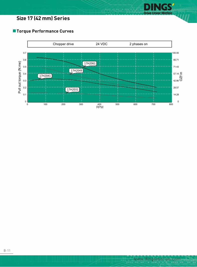
B-11
www.dingsmotion.com
Torque Performance Curves
0.7
0.6
0.5
0.4
0.3
0.2
0.1
00 100 200 300 400 500 600 700 800
RPM
Chopper drive 24 VDC 2 phases on
Pul
l out
torq
ue (N
.me)
100.00
85.71
71.43
57.14
42.86
28.57
14.28
0
OZf
·in
17H2061
17H2041
17H2031
17H2049
Size 17 (42 mm) Series

B-12
www.dingsmotion.com
Dimensional Drawing
General
Accuracy
Step angle 1.8°±5%
Resistance ±10% / 20 C
Inductance ±20% / 1KHz
Insulation class B
Duty type S1
Dielectrical strength 500 VAC / 1 KHz / 1 mA / 1 s
Insulation resistance 100 MΩ / 500 VDC
Permissible radial load(5MM distance from mounting surface)
Permissible radial load(10MM distance from
mounting surface)
Permissible radial load(15MM distance from
mounting surface)
Permissible radial load(20MM distance from
mounting surface)
180N 130N 100N 90N
Parameter
Type Current(A)
Resistance (Ω)
Inductance (mH)
Holding Torque (N·m)
Rotor Inertia (g·cm2)
Length (mm)
Mass (g)
23H2042 1 4.2 11 0.6 140 42.5 460
23H2051 2 1.5 4.4 1 240 51.5 640
23H2065 3 0.9 3.6 1.7 350 65.5 860
23H2076 4 0.6 2.4 2 480 76.5 1060
Material
End bell Aluminum alloy
Bearing Deep groove ball bearing
Magnet Sintered NdFeB
Shaft Stainless steel
Wiring UL 3265,22 AWG
Parameters
0 0.05
Size 23 (57 mm) Series

B-13
www.dingsmotion.com
Torque Performance Curves
2.00
1.80
1.60
1.40
1.20
1.00
0.80
0.60
0.40
0.20
0.00
285.71
257.14
228.57
200.00
171.42
142.85
114.28
85.71
57.14
28.57
0
RPM
Chopper drive 48 VDC 2 phases on
Pul
l out
torq
ue (N
.me)
OZf
·in
23H2076
0 200 400 600 800 1000 1200 1400
23H2065
23H2051
23H2042
Size 23 (57 mm) Series

B-14
www.dingsmotion.com
Dimensional Drawing
General
Accuracy
Step angle 1.8°±5%
Resistance ±10% / 20 C
Inductance ±20% / 1KHz
Insulation class B
Duty type S1
Dielectrical strength 500 VAC / 1 KHz / 1 mA / 1 s
Insulation resistance 100 MΩ / 500 VDC
Permissible radial load(5MM distance from mounting surface)
Permissible radial load(10MM distance from
mounting surface)
Permissible radial load(15MM distance from
mounting surface)
Permissible radial load(20MM distance from
mounting surface)
210N 170N 140N 120N
Parameter
Type Current(A)
Resistance (Ω)
Inductance (mH)
Holding Torque (N·m)
Rotor Inertia (g·cm2)
Length (mm)
Mass (g)
24H2047 2 1.5 3.9 0.9 240 47 600
24H2056 3 0.8 3 1.3 340 56 800
24H2068 4 0.6 2.5 2.2 490 68 1000
24H2085 5 0.4 1.8 2.5 690 85 1300
Material
End bell Aluminum alloy
Bearing Deep groove ball bearing
Magnet Sintered NdFeB
Shaft Stainless steel
Wiring UL 3265,20 AWG
Parameters
0 0.05
Size 24 (60 mm) Series

B-15
www.dingsmotion.com
Torque Performance Curves
2.5
2.0
1.5
1.0
0.5
0
RPM
Chopper drive 48 VDC 2 phases on
Pul
l out
torq
ue (N
.me)
357.15
285.72
214.28
142.86
71.43
0
OZf
·in
24H2085
0 200 400 600 800 1000 1200 1400
24H2068
24H2056
24H2047
Size 24 (60 mm) Series

B-16
www.dingsmotion.com
Dimensional Drawing
General
Accuracy
Step angle 1.8°±5%
Resistance ±10% / 20 C
Inductance ±20% / 1KHz
Insulation class B
Duty type S1
Dielectrical strength 500 VAC / 1 KHz / 1 mA / 1 s
Insulation resistance 100 MΩ / 500 VDC
Permissible radial load(5MM distance from mounting surface)
Permissible radial load(10MM distance from
mounting surface)
Permissible radial load(15MM distance from
mounting surface)
Permissible radial load(20MM distance from
mounting surface)
390N 340N 290N 260N
Parameter
Type Current(A)
Resistance (Ω)
Inductance (mH)
Holding Torque (N·m)
Rotor Inertia (g·cm2)
Length (mm)
Mass (g)
34H2060 3 1 6 2.6 1100 60.5 1600
34H2075 4.5 0.6 6 4.5 1800 75 2100
34H2098 6 0.5 5.5 7.2 2800 98 2900
Material
End bell Aluminum alloy
Bearing Deep groove ball bearing
Magnet Sintered NdFeB
Shaft Stainless steel
Wiring UL 3265,18 AWG
Parameters
Size 34 (86 mm) Series

B-17
www.dingsmotion.com
Torque Performance Curves
7.0
6.0
5.0
4.0
3.0
2.0
1.0
0
RPM
Chopper drive 60 VDC 2 phases on
Pul
l out
torq
ue (N
.me)
1000.00
857.14
714.28
571.43
428.57
285.71
142.86
0
OZf
·in
34H2096
0 200 400 600 800 1000 1200 1400
34H2060
34H2075
Size 34 (86 mm) Series

B-18
www.dingsmotion.com
Planetary GearboxOverview
Frame size Ratio Rated torque(N.m)
Limit torque(N.m) Stages Efficiency
(%)Length(mm)
Mass(g)
Corresponding motor
22 mm
4 0.03 0.09 1 81 16.3 29.1
20 mm15
0.05 0.15 2 66 16.3 30.120
107 0.1 0.3 3 53 19.5 36
28 mm
3.30.5 1.5 1 90 21.2 87
28 mm
4.6
11.2
1 3 2 81 26.9 9115.5
21.5
37.72.5 7.5 3 73 32.7 100
72
32 mm
3.30.5 1.5 1 90 16.2 90
35 mm
4.6
11.2
1 3 2 81 21.9 11515.5
21.5
37.72.5 7.5 3 73 27.7 140
72
42 mm
3.71 3 1 90 30.6 260
42 mm
5.2
13.7
2 6 2 81 41.9 35019.2
26.9
50.9
5 15 3 73 53.2 44071.2
99.5
57 mm
56 12 1 95 53 800
57 mm
10
15
25 40 2 90 70 110020
25
60 mm
5
6 12 1 95 53 900
60 mm
10
15
2025 40 2 90 70 1200
25
Accessories and Options

B-19
www.dingsmotion.com
22 mm Frame Planetary GearboxDimensional Drawing
Parameters
House material Metal
No load backlash 1°
Bearing Sleeve bearing
Ratio Rated torque(N.m)
Limit torque(Kgf·cm) Stages Efficiency
(%)Length(mm)
Mass(g)
4 0.03 0.09 1 81 16.3 29.1
150.05 0.15 2 66 16.3 30.1
20
107 0.1 0.3 3 53 19.5 36
Accessories and Options

B-20
www.dingsmotion.com
28 mm Frame Planetary GearboxDimensional Drawing
Parameters
House material Metal
No load backlash 1°
Bearing Ball bearing
Ratio Rated torque(N.m)
Limit torque(N.m) Stages Efficiency
(%)Length(mm)
Mass(g)
3.30.5 1.5 1 90 21.2 87
4.6
11.2
1 3 2 81 26.9 9115.5
21.5
37.72.5 7.5 3 73 32.7 100
72
Accessories and Options

B-21
www.dingsmotion.com
32 mm Frame Planetary GearboxDimensional Drawing
House material Metal
No load backlash 1°
Bearing Ball bearing
Ratio Rated torque(N.m)
Limit torque(N.m) Stages Efficiency
(%)Length(mm)
Mass(g)
3.30.5 1.5 1 90 16.2 90
4.6
11.2
1 3 2 81 21.9 11515.5
21.5
37.72.5 7.5 3 73 27.7 140
72
Parameters
Accessories and Options

B-22
www.dingsmotion.com
42 mm Frame Planetary GearboxDimensional Drawing
Parameters
House material Metal
No load backlash 1.2°
Bearing Ball bearing
Ratio Rated torque(N.m)
Limit torque(N.m) Stages Efficiency
(%)Length(mm)
Mass(g)
3.71 3 1 90 30.6 260
5.2
13.7
2 6 2 81 41.9 35019.2
26.9
50.9
5 15 3 73 53.2 44071.2
99.5
Accessories and Options

B-23
www.dingsmotion.com
57 mm Frame Planetary GearboxDimensional Drawing
Parameters
House material Metal
No load backlash One stage 15 arcmin, two stages 25 arcmin
Bearing Ball bearing
Ratio Rated torque(N.m)
Limit torque(N.m) Stages Efficiency
(%)Length(mm)
Mass(g)
56 12 1 95 53 800
10
15
25 40 2 90 70 110020
25
Accessories and Options

B-24
www.dingsmotion.com
60 mm Frame Planetary GearboxDimensional Drawing
Parameters
House material Metal
No load backlash One stage 15 arcmin, two stages 25 arcmin
Bearing Ball bearing
Ratio Rated torque(N.m)
Limit torque(N.m) Stages Efficiency
(%)Length(mm)
Mass(g)
56 12 1 95 53 900
10
15
25 40 2 90 70 120020
25
Accessories and Options

B-25
www.dingsmotion.com
Optional Encoder
EK1 Encoder – differential outputEK1 Encoder – single ended output
0.4711.94
0.51
12.95
0.85
21.63
0.4511.33
0.74
18.89
1.2231.05
1.86
47.14
0.6516.59
1.2231.05
2.04
51.76
0.6516.59
1.11
R28.19
2.84
72.14
0.6516.59
1.11
R28.19
2.99
75.95
0.6516.59
李欢 鼎智编码器A3
图纸 1 (共1)比例:
品号:
姓名
材料
批准标准化工艺审核绘制
X.±0.76
日期
.X±0.25.XX±0.13.XXX±0.013
毫米(mm)英寸(inch).X±0.03
.XXXX±0.0005
.XX±0.01.XXX±0.005
角度±1°
其余公差执行标准
常州市鼎智机电有限公司DINGS’ MOTION
品名:
0.8722
0.
5112
.95
0.5814.61
0.4511.33
0.79 19
.96
李欢
EK1
EK2
EK3
适配20、28、35、42电机
适配35、42、57电机
适配57、86电机
EK1编码器带差分输出
分辨率 100 108 120 125 128 200 250 256 300 360 400 500单端 0 1 2 3 4 5 6 7 8 9 10 11差分 A B C D E F G H I J K L
分辨率 64 100 200 500 1000 1800 2000 2500 3600 4000 5000 7200 8000 10000单端 0 1 2 3 4 5 6 7 8差分 A B C D E F G H I J K L M
分辨率 50 100 192 200 250 256 360 400 500 720 900 1000 1250 2000 2500 4000 5000单端 0 1 2 3 4 5 6 7 8 9 10 11 12差分 A B C D E F G H I J K L M N O P Q
鼎智编码器②A3
图纸 1 (共1)比例:
品号:
姓名材料
批准标准化工艺审核绘制
X.±0.76
日期
.X±0.25.XX±0.13
.XXX±0.013
毫米(mm)英寸(inch).X±0.03
.XXXX±0.0005
.XX±0.01.XXX±0.005
角度±1°其余公差执行标准
常州市鼎智机电有限公司DINGS’ MOTION
品名:
EK1 Encoder (Used for Size 8, 11, 14, 17 Motor)* No index
Resolution(CPR) 100 108 120 125 128 200 250 256 300 360 400 500
Single ended output 0 1 2 3 4 5 6 7 8 9 10 11
Differential output A B C D E F G H I J K L
Accessories and Options
EK2 Encoder – single ended output EK2 Encoder – differential output
0.4711.94
0.51
12.95
0.85
21.63
0.4511.33
0.74
18.89
1.2231.05
1.86
47.14
0.6516.59
1.2231.05
2.04
51.76
0.6516.59
1.11
R28.19
2.84
72.14
0.6516.59
1.11
R28.19
2.99
75.95
0.6516.59
李欢 鼎智编码器A3
图纸 1 (共1)比例:
品号:
姓名
材料
批准标准化工艺审核绘制
X.±0.76
日期
.X±0.25.XX±0.13.XXX±0.013
毫米(mm)英寸(inch).X±0.03
.XXXX±0.0005
.XX±0.01.XXX±0.005
角度±1°
其余公差执行标准
常州市鼎智机电有限公司DINGS’ MOTION
品名:
0.4711.94
0.51
12.95
0.85
21.63
0.4511.33
0.74
18.89
1.2231.05
1.86
47.14
0.6516.59
1.2231.05
2.04
51.76
0.6516.59
1.11
R28.19
2.84
72.14
0.6516.59
1.11
R28.19
2.99
75.95
0.6516.59
李欢 鼎智编码器A3
图纸 1 (共1)比例:
品号:
姓名
材料
批准标准化工艺审核绘制
X.±0.76
日期
.X±0.25.XX±0.13.XXX±0.013
毫米(mm)英寸(inch).X±0.03
.XXXX±0.0005
.XX±0.01.XXX±0.005
角度±1°
其余公差执行标准
常州市鼎智机电有限公司DINGS’ MOTION
品名:EK2 Encoder (Used for Size 14, 17, 23 Motor)* Index /No index
Resolution(CPR) 50 100 192 200 250 256 360 400 500 720 900 1000 1250 2000 2500 4000 5000
Single ended output 0 1 2 3 4 5 6 7 8 9 10 11 12
Differential output A B C D E F G H I J K L M N O P Q
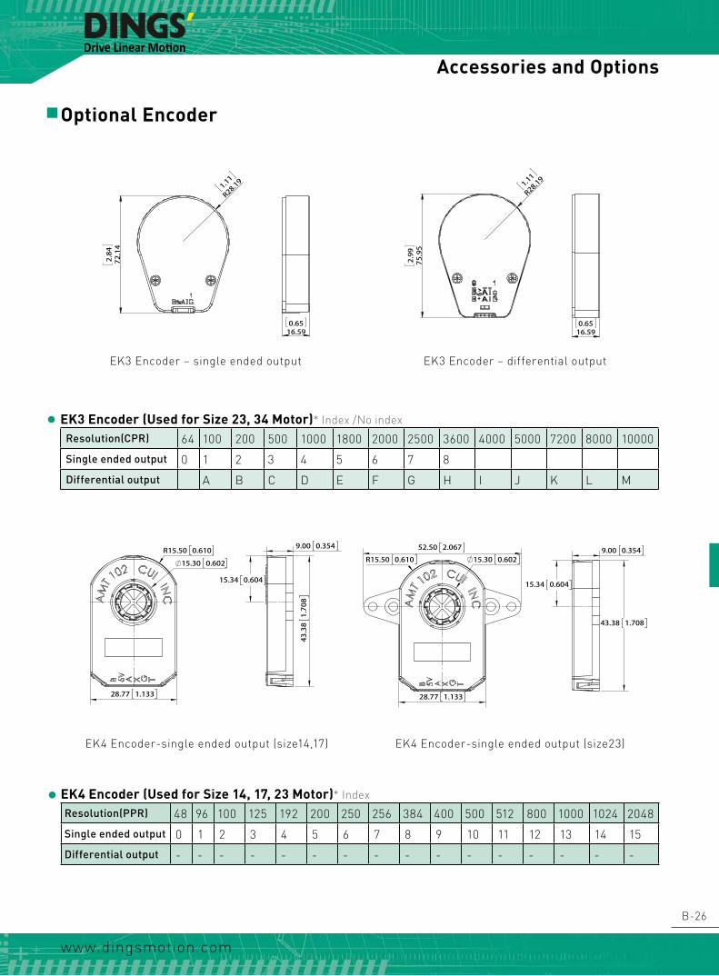
B-26
www.dingsmotion.com
Optional Encoder
Accessories and Options
EK3 Encoder (Used for Size 23, 34 Motor)* Index /No index
Resolution(CPR) 64 100 200 500 1000 1800 2000 2500 3600 4000 5000 7200 8000 10000
Single ended output 0 1 2 3 4 5 6 7 8
Differential output A B C D E F G H I J K L M
EK3 Encoder – single ended output EK3 Encoder – differential output
0.4711.94
0.51
12.95
0.85
21.63
0.4511.33
0.74
18.89
1.2231.05
1.86
47.14
0.6516.59
1.2231.05
2.04
51.76
0.6516.59
1.11
R28.19
2.84
72.14
0.6516.59
1.11
R28.19
2.99
75.95
0.6516.59
李欢 鼎智编码器A3
图纸 1 (共1)比例:
品号:
姓名
材料
批准标准化工艺审核绘制
X.±0.76
日期
.X±0.25.XX±0.13.XXX±0.013
毫米(mm)英寸(inch).X±0.03
.XXXX±0.0005
.XX±0.01.XXX±0.005
角度±1°
其余公差执行标准
常州市鼎智机电有限公司DINGS’ MOTION
品名:
0.4711.94
0.51
12.95
0.85
21.63
0.4511.33
0.74
18.89
1.2231.05
1.86
47.14
0.6516.59
1.2231.05
2.04
51.76
0.6516.59
1.11
R28.19
2.84
72.14
0.6516.59
1.11
R28.19
2.99
75.95
0.6516.59
李欢 鼎智编码器A3
图纸 1 (共1)比例:
品号:
姓名
材料
批准标准化工艺审核绘制
X.±0.76
日期
.X±0.25.XX±0.13.XXX±0.013
毫米(mm)英寸(inch).X±0.03
.XXXX±0.0005
.XX±0.01.XXX±0.005
角度±1°
其余公差执行标准
常州市鼎智机电有限公司DINGS’ MOTION
品名:
EK4 Encoder (Used for Size 14, 17, 23 Motor)* Index
Resolution(PPR) 48 96 100 125 192 200 250 256 384 400 500 512 800 1000 1024 2048
Single ended output 0 1 2 3 4 5 6 7 8 9 10 11 12 13 14 15
Differential output - - - - - - - - - - - - - - - -
EK4 Encoder-single ended output (size14,17) EK4 Encoder-single ended output (size23)
R15.50 0.610
15.30 0.602
9.00 0.354
15.34 0.604
43.38 1.708
52.50 2.067
R15.50 0.610
28.77 1.133
9.00 0.354
15.34 0.604
43.38 1.708
28.77 1.133
15.30 0.602
R15.50 0.610
15.30 0.602
9.00 0.354
15.34 0.604
43.38 1.708
52.50 2.067
R15.50 0.610
28.77 1.133
9.00 0.354
15.34 0.604
43.38 1.708
28.77 1.133
15.30 0.602

B-27
www.dingsmotion.com
Optional Encoder
Accessories and Options
EK6 Encoder – differential output
EK6 Encoder (Used for Size 11, 14, 17 Motor)* No index
Resolution(PPR) 100 200 400 500 1000 2000 10000 Non-standard custom
Differential output 0 1 2 3 4 5 6
[1.10]4-28
[0.59]15
[0.47]12
[1.2
6]32
TECHNICAL PARAMETERSEK6编码器差分输出
REVISION
REV. DATE DESCRIPTION DRAWN BY
01 2012/05/26 后出轴15改为25
02 2014/02/07 增加接插件JST PHR-4
03 2015/12/10 电机外形变更 李欢
D
E
F
C
1 2 3 4
B
A
321 5
C
D
4 6 7 8
A
B
Linear Actuator
11E2034A4-050-004
常州市鼎智机电有限公司DINGS' MOTION
MFG'D 工艺A3
SHEET 1 OF 1SCALE:
DWG NO.
TITLE:
DATE 日期 线性步进电机
技术规格书Specification
2011.12.15
UNLESS OTHERWISE SPECIFIED:其余未注事项:DIMENSIONS ARE IN MILLIMETERS尺寸单位为毫米(mm). TOLERANCES AS BELOW:未注公差按以下标准:
毫米 mm英寸 inch
客户 Customer
Checkd 审核
Name 姓名
APPV'D 批准QA 质量
DRAWN 设计
ANGLE ±1° 角度 ±1°
.X ±0.04 X. ±1.XX ±0.01
.XXX ±0.005.XXXX ±0.0005
.X ±0.25.XX ±0.13
.XXX ±0.013
珠海科域
视图 重要尺寸 ▲
李欢
EK5 Encoder (Used for Size 8, 11, 14, 17 Motor)* Index
Resolution(CPR) 360 500 512 1000 1024 2000 2048
Single ended output 0 1 2 3 4 5 6
Differential output A B C D E F G
Preliminary datasheet - Confidential for internal use only
Package Dimension
Mounting consideration
All dimension in mm Note: 1. No limit for cover with hole option Pin configuration
Pin Differential Single Ended(TTL) 1 GND GND 2 Ch A+ Ch A+ 3 Ch A- NA 4 Vcc Vcc 5 Ch B+ Ch B+ 6 Ch B- NA 7 Ch I- NA 8 Ch I+ Ch I+
EK5 Encoder – differential output

www.dingsmotion.com
C-1
DINGS' ELECTRICAL & MECHANICAL Co., Ltd.
C Hollow Shaft Hybrid Stepper
These Hollow shaft motor have 6 different sizes, from 20mm to 86mm. Each size has different stack lengths. Different sizes of inner holes, front and rear shafts can be provided. In addition, we can also customize the non-standard end machining of the shaft.
Part number construction
Product overview
Size 8 · 20 mm series
Size 11 · 28 mm series
Size 14 · 35 mm series
Size 17 · 42 mm series
Size 23 · 57 mm series
Size 34 · 86 mm series
C-2
C-3
C-4
C-6
C-8
C-10
C-12
C-14
Drive Linear Motion

www.dingsmotion.com
C-2
Example
Naming code 17HS2034-4D-100-001Description Size 42 mm Hollow shaft Step angle 1.8° Motor length 34 mm 4 wiring leads Dual shaft Customization sequence 01
Part Number Construction
17 HS 2 034 4 D 100 001
1 2 3 4 5 6 7 8
NEMA Size (mm)
NEMA
MOTOR SIZE (mm)
Motor Type
H = hollow shaft
Step Aangle (°)
2 = 2 phase with 1.8°
4 = 2 phase with 0.9°
Motor Length/Stack
034 = motor length
Number of Lead Wires
4 = qty 4 flying leads
6 = qty 6 flying leads
Shaft Configuration
D = double
S = single
Rated Current
100 = 1.0A
Customer Sequence Number
08
20
11
28
14
35
17
42
23
57
34
86
24
60

www.dingsmotion.com
C-3
Size (mm) Motor length (mm)
Holding torque (N.m)
Inner holes (mm)
Power consumption (W)
8 (20*20)27.2 0.014 3 2.4
38.1 0.02 3 4
11 (28*28)33.35 0.053 5 4.2
45 0.117 5 7.5
14 (35*35)33.6 0.19 8 5.7
45.6 0.36 8 9.1
17 (42*42)34.1 0.31 8 7
48.1 0.56 8 13
23 (57*57)45 1.2 13 13
65 2.1 13 25
34 (86*86) 76 4.5 16 31
Product Overview

www.dingsmotion.com
C-4
Model No.Rated
Voltage(V)
Current (A)
Resistance(Ω)
Inductance (mH)
Holding Torque(N.m)
Detent Torque(N.m)
Motor length“L”(mm)
8HS2028 2.55 0.5 5.1 1.5 0.014 0.002 27.2
8HS2038 4.4 0.5 8.8 2.7 0.020 0.002 38.1
10 1
10 1
20
15.4 0.15
4-M2 2min
1.5 0.2
L 0.5
5+ 0 - 0.012
16+ 0 - 0.05
3 thru+ 0.2- 0
5
6
+ 0 - 0.012
320 20
4 leads
AWG#28
Motor Characteristics
Dimensional Drawings
Size 8 (20mm) Series

www.dingsmotion.com
C-5
Size 8 (20mm) Series
Torque Performance Curves
RPM r/minPPS
30100
60200
180600
300 1000
4501500
6002000
9003000
7502500
15005000
12004000
N.m
0.020
0.016
0.012
0.008
0.004
0.000
8HS2028-4D-050
8HS2038-4D-050
Drive method: Chopper drive(DS-2422-001)Drive voltage: 24VDCMicro step: No

www.dingsmotion.com
C-6
Size 11 (28mm) Series
Model No.Rated
Voltage(V)
Current (A)
Resistance(Ω)
Inductance (mH)
Holding Torque(N.m)
Detent Torque(N.m)
Motor length“L”(mm)
11HS2033 2.1 1.0 2.1 1.5 0.053 0.004 33.5
11HS2045 4.1 1.0 4.1 4.0 0.117 0.004 45
Motor Characteristics
Dimensional Drawings
10 1
10 1
23 0.228
4-M2.5 2.5min
1.5 0.2
L 0.5
7
6
+ 0 - 0.012
7+ 0 - 0.012
22+ 0 - 0.05
5 thru+ 0.2- 0
320 20
4 leads
AWG#26

www.dingsmotion.com
C-7
Size 11 (28mm) Series
Torque Performance Curves
RPM r/minPPS
30100
60200
180600
300 1000
4501500
6002000
9003000
7502500
15005000
12004000
N.m
0.12
0.10
0.08
0.06
0.04
0.02
0.00
11HS2033-4D-100
11HS2045-4D-100
Drive method: Chopper drive(DS-2422-001)Drive voltage:24VDCMicro step: No

www.dingsmotion.com
C-8
Size 14 (35mm) Series
Model No.Rated
Voltage(V)
Current (A)
Resistance(Ω)
Inductance (mH)
Holding Torque(N.m)
Detent Torque(N.m)
Motor length“L”(mm)
14HS2033 3.5 1.0 3.5 3.6 0.19 0.008 33.6
14HS2045 6 1.0 6 7.2 0.36 0.013 45.6
Motor Characteristics
Dimensional Drawings
20 1
20 1
26 0.235
4-M3 4min
1.8 0.2
L 0.5
10
6
+ 0 - 0.012
10+ 0 - 0.012
22+ 0 - 0.05
8 thru+ 0.2- 0
320 20
4 leads
AWG#26

www.dingsmotion.com
C-9
Size 14 (35mm) Series
Torque Performance Curves
RPM r/minPPS
30100
60200
180600
300 1000
4501500
6002000
9003000
7502500
15005000
12004000
N.m
0.30
0.25
0.20
0.15
0.10
0.05
0.00
14HS2033-4D-100
14HS2045-4D-100
Drive method: Chopper drive(DS-2422-001) Drive voltage: 24VDCMicro step: No

www.dingsmotion.com
C-10
Size 17 (42mm) Series
Model No.Rated
Voltage(V)
Current (A)
Resistance(Ω)
Inductance (mH)
Holding Torque(N.m)
Detent Torque(N.m)
Motor length“L”(mm)
17HS2034 3.8 1.0 3.8 5.0 0.31 0.014 34.1
17HS2048 2.5 2.5 1.0 1.8 0.56 0.018 48.1
Motor Characteristics
Dimensional Drawings
20 1
20 1
31 0.242.2
4-M3 4min
1.8 0.2L 0.5
10
6
+ 0 - 0.012
22+ 0 - 0.05
8 thru+ 0.2- 0
10+ 0 - 0.012
320 20
4 leads
AWG#26

www.dingsmotion.com
C-11
Size 17 (42mm) Series
Torque Performance Curves
RPM r/minPPS
30100
60200
180600
300 1000
4501500
6002000
9003000
7502500
15005000
12004000
N.m
0.40
0.35
0.30
0.25
0.20
0.15
0.10
0.05
0.00
17HS2034-4D-100
17HS2048-4D-250
Drive method: Chopper drive(DS-2422-001) Drive voltage: 24VDCMicro step: No

www.dingsmotion.com
C-12
Size 23 (57mm) Series
Model No.Rated
Voltage(V)
Current (A)
Resistance(Ω)
Inductance (mH)
Holding Torque(N.m)
Detent Torque(N.m)
Motor length“L”(mm)
23HS2045 3.5 2.0 1.75 4.1 1.2 0.020 45
23HS2065 5.0 2.5 2.0 5.2 2.1 0.040 65
Motor Characteristics
Dimensional Drawings
20 1
20 1
47.14 0.2556.2
4- 5.2
1.5 0.2
5
L 0.5
15
6
+ 0 - 0.012
15+ 0 - 0.012
12 thru+ 0.2- 0
38+ 0 - 0.05
320 20
4 leads
AWG#22

www.dingsmotion.com
C-13
Size 23 (57mm) Series
Torque Performance Curves
RPM r/minPPS
30100
60200
180600
300 1000
4501500
6002000
9003000
7502500
15005000
12004000
N.m
1.4
1.2
1.0
0.8
0.6
0.4
0.2
0.0
23HS2045-4D-200
23HS2065-4D-250
Drive method: Chopper drive(DS-5045-003)Drive voltage: 40VDCMicro step: No

www.dingsmotion.com
C-14
Size 34 (86mm) Series
Model No.Rated
Voltage(V)
Current (A)
Resistance(Ω)
Inductance (mH)
Holding Torque(N.m)
Detent Torque(N.m)
Motor length“L”(mm)
34HS2076 5.7 3.0 1.9 19 4.5 0.095 76
Motor Characteristics
Dimensional Drawings
20 1
20 1
69.3 0.2586
4- 6.5
76 0.5
20
6
+ 0 - 0.012
73
10
+ 0 - 0.05
16 thru+ 0.2- 0
20+ 0 - 0.012
320 20
4 leads
AWG#20

www.dingsmotion.com
C-15
Size 34 (86mm) Series
Torque Performance Curves
RPM r/minPPS
30100
60200
180600
300 1000
4501500
6002000
7502500
N.m
4.0
3.5
3.0
2.5
2.0
1.5
1.0
0.5
0.0
34HS2076-4D-300
Drive method: Chopper drive(DS-5045-003)Drive voltage: 40VDCMicro step: No

D-1
www.dingsmotion.com
The outstanding advantages of BLDC motor is the convenience of start and speed regulation, higher power density and over load capacity.With 4 frame sizes from NEMA 17 to NEMA 34 and 3 stack lengths per frame, we supply rotation drive from 30 W to 1.5 KW.
Part number construction
Size 17 · 42 mm series
Size 23 · 57 mm series
Size 24 · 60 mm series
Size 34 · 86 mm series
D-2
D-3
D-4
D-5
D-6
DINGS' ELECTRICAL & MECHANICAL Co., Ltd.
D Brushless DC Motor

D-2
www.dingsmotion.com
ExampleNaming code M17L3-001
Description 42 mm frame size, Ordinary type 94 mm length, Customization sequence code 001
Motor M = motor D = drive E = motor with integrated driveFrame Size
Derivations Based On Different Magnetic, Insulation Or Other Customization E.G. L = ordinary type, K = servo type stator, P = protective structureLength CodeCustomization sequence Code
CODEMOTOR SIZE (mm)
1742
2357
2460
3486
Part Number Construction

D-3
www.dingsmotion.com
M17 Frame M17L1 M17L2 M17L3General
insulation Class BDuty Type S1
feed Back Method Hall SensorsCommutation Angle 120°Dielectrical Strength 500 VAC / 1 KHz / 1 mA / 1 sinsulation Resistance 100 MOhm / 500 VDC
Performancenominal Voltage Un V 24
Rated Power Pn W 31 63 94Rated Torque Tn N•m 0.1 0.2 0.3Rated Speed Nn RPM 3000
Rated Current In A 1.9 3.7 5.6Resistance(line-line) Rn Ohm 2 1 0.6inductance(line-line) L mH 1 0.6 0.4winding Connection - - Star Delta
Pole Pairs - - 4Length LT mm 47 67 87Mass - Kg 0.3 0.5 0.7
MaterialEnd Cover Aluminium Alloy
Bearing Deep Groove Ball BearingsMagnetic Sinter NdFeB
Shaft Carbon Steel
Size 17 (42mm) Series

D-4
www.dingsmotion.com
M23 Frame M23L1 M23L2 M23L3General
Insulation Class BDuty Type S1
Feed Back Method Hall SensorsCommutation Angle 120°Dielectrical Strength 500 VAC / 1 KHz / 1 mA / 1 sInsulation Resistance 100 MOhm / 500 VDC
PerformanceNominal Voltage Un V 48
Rated Power Pn W 63 126 188Rated Torque Tn N•m 0.2 0.4 0.6Rated Speed Nn RPM 3000
Rated Current In A 1.9 3.7 5.6Resistance(line-line) Rn Ohm 2.5 1.1 0.8Inductance(line-line) L mH 3 1.3 0.9Winding Connection - - Star
Pole Pairs - - 4Length LT mm 58 78 98Mass - Kg 0.7 1 1.3
MaterialEnd Cover Aluminium Alloy
Bearing Deep Groove Ball BearingsMagnetic Sinter NdFeB
Shaft Carbon Steel
Size 23 (57mm) Series

D-5
www.dingsmotion.com
Size 24 (60mm) Series
M24 Frame M24L1 M24L2 M24L3General
insulation Class BDuty Type S1
feed Back Method Hall SensorsCommutation Angle 120°Dielectrical Strength 500 VAC / 1 KHz / 1 mA / 1 sinsulation Resistance 100 MOhm / 500 VDC
Performancenominal Voltage Un V 48
Rated Power Pn W 79 157 236 Rated Torque Tn N•m 0.25 0.5 0.75Rated Speed Nn RPM 3000
Rated Current In A 2.3 4.7 7.0 Resistance(line-line) Rn Ohm 1.8 0.9 0.5inductance(line-line) L mH 2.3 1.1 0.7winding Connection - - Star
Pole Pairs - - 4Length LT mm 64 85 106Mass - Kg 0.8 1.2 0.6
MaterialEnd Cover Aluminium Alloy
Bearing Deep Groove Ball BearingsMagnetic Sinter NdFeB
Shaft Carbon Steel

D-6
www.dingsmotion.com
Size 34 (86mm) Series
M34 Frame M34L1 M34L2 M34L3General
insulation Class BDuty Type S1
feed Back Method Hall SensorsCommutation Angle 120°Dielectrical Strength 500 VAC / 1 KHz / 1 mA / 1 sinsulation Resistance 100 MOhm / 500 VDC
Performancenominal Voltage Un V 48
Rated Power Pn W 220 346 440 Rated Torque Tn N•m 0.7 1.1 1.4Rated Speed Nn RPM 3000
Rated Current In A 6.5 10.3 13.1 Resistance(line-line) Rn Ohm 0.3 0.2 0.2inductance(line-line) L mH 0.7 0.5 0.4winding Connection - - Star Delta
Pole Pairs - - 4Length LT mm 66.5 80.5 93.5Mass - Kg 1.8 2.3 2.8
MaterialEnd Cover Aluminium Alloy
Bearing Deep Groove Ball BearingsMagnetic Sinter NdFeB
Shaft Carbon Steel

E-1
www.dingsmotion.com
E Stepper Motor Driver
DINGS supplies drivers based on the latest 32 bit DSP and digital microstep technology. It enables to create smooth commutation of advanced performances, accurate positioning, less noise and lower temperature. In addition, closed loop and integrated drive options are available.
DS-2422-001
DS-5045-003
DS-2MSD8078-2
DS-OL17/23-I series
ST-484 closed-loop driver
Vector series integrated driver
DS-CL28-SA Integrated closed-loop driver
E-2
E-3
E-4
E-5
E-11
E-13
E-18

E-2
www.dingsmotion.com
Installation Instructions1. Reliable operation temperature for Driver should be less than 60°C [135°F] and motor should be less than 85°C [176°F]2. Recommend to use Automatic Idle-Current mode. It enables to reduce current as 60% when motor stops then help to minimize heating of motor and driver.3. Recommend to mount driver vertically to maximize heat sink area. If necessary, please apply additional cooling method to cool-down the system.
(Side mounting, Good heat dissipation)
DS-2422-001
Preparations To Operate1. Recommend to use appropriate power supply [8~36VDC]2. Controller, PLC or controller block [High speed pulse]3. Recommend to use 2 phase, 4 lead wire of Step motors.
Power Supply Connection1. Power supply range is 8~36VDC but recommend to select 24V available under Size 8, 11, 14, 17 of Step motors.2. Please connect "+" to the "VDC" and "-" to the GND.
Description Min Rating Max
Current RMS(A) 0.2 - 2.2
Power Voltage(VDC) 8 24 36
Signal current(mA) 6 10 16
Pulse frequency(KHz) 0 - 300
Pulse width(us) 2 - -
Direction signal width(us) 100 - -
undervoltage protec-tion(VDC) - 7.5 -
overvoltage protection(VDC) - 42 -
Cooling mode Natural cooling
Ambient temperature(oC) 0~50
Ambient humidity(%RH) 40~90%
Vibration 10~55HZ/0.15mm
Storage temperature(oC) -20~65
weight(g) 180
DS-2422-001Fit 20 28 35 42 Motor

E-3
www.dingsmotion.com
DS-5045-003 DriverFit 35 42 57 86 Motor
(Side mounting, Good heat dissipation)
Installation Instructions1. Reliable operation temperature for Driver should be less than 60°C [135°F] and motor should be less than 85°C [176°F]2. Recommend to use Automatic Idle-Current mode. It enables to reduce current as 60% when motor stops then help to minimize heating of motor and driver.3. Recommend to mount driver vertically to maximize heat sink area. If necessary, please apply additional cooling method to cool-down the system.
Preparations To Operate1. Recommend to use appropriate power supply [18~90VDC]2. Controller, PLC or controller block [High speed pulse]3. Recommend to use 2 phase, 4 lead wire of Step motors.
Power Supply Connection1. Power supply range is 18~90VDC but recommend to select 24V available under Size 14, 17, 23, 24, 34 of Step motors.2. Please connect "+" to the "VDC" and "-" to the GND.
Description Min Rating Max
Current RMS(A) 1.0 - 4.5
Power Voltage(VDC) 18 50 90
Signal current(mA) 5 10 20
Pulse frequency(KHz) 0 - 300
Pulse width(us) 2 - -
Direction signal width(us) 100 - -
undervoltage protec-tion(VDC) - 17.5 -
overvoltage protection(VDC) - 95 -
Cooling mode Natural cooling
Ambient temperature(oC) 0~50
Ambient humidity(%RH) 40~90%
Vibration 10~55HZ/0.15mm
Storage temperature(oC) -20~65
weight(g) 270
DS-5045-003

E-4
www.dingsmotion.com
DS-2MSD8078-2 DriverFit 57 86 Motor
(Side mounting, Good heat dissipation)
Installation Instructions1. Reliable operation temperature for Driver should be less than 60°C [135°F] and motor should be less than 85°C [176°F]2. Recommend to use Automatic Idle-Current mode. It enables to reduce current as 60% when motor stops then help to minimize heating of motor and driver.3. Recommend to mount driver vertically to maximize heat sink area. If necessary, please apply additional cooling method to cool-down the system.
Preparations To Operate1. Recommend to use appropriate power supply [36~80VDC]2. Controller, PLC or controller block [High speed pulse]3. Recommend to use 2 phase, 4 lead wire of Step motors.
Power Supply Connection1. Power supply range is 36~80VDC but recommend to select 24V available under Size 23, 24, 34 of Step motors.2. Please connect "+" to the "VDC" and "-" to the GND.
Description Min Rating Max
Current RMS(A) 2.8 - 7.8
Power Voltage(VDC) 36 68 80
Signal current(mA) 7 10 16
Pulse frequency(KHz) 0 - 300
Pulse width(us) 2 - -
Direction signal width(us) 100 - -
undervoltage protec-tion(VDC) - - -
overvoltage protection(VDC) - - -
Cooling mode Natural cooling
Ambient temperature(oC) 0~40
Ambient humidity(%RH) 40~90%
Vibration 10~55HZ/0.15mm
Storage temperature(oC) -20~65
weight(g) 570
DS-2MSD8078-2

E-5
www.dingsmotion.com
SummaryRear motor mounted integrated drive, compact dimension, accurate current and complete protection with RS232, RS485 and CAN2.0 configurations, DS-OL17/23-I Series, allows performances for long distance communication, real-time response and anti-resonance, smoother acceleration and quick deceleration as 0.5sec from 3,000RPM. Fully aluminium housing provides rigid housing protection and fast cooling efficiency.
1.Multiple control mode, Pul/DIR, RS232, RS485 and CAN2.0 communication.
Infegrated Positioning Drice DS-OL17/23-I Series
脉冲控制
RS-485
CAN总成
IDn
ID5 ID4 ID3 ID2 ID1
ID2 ID1
• •• •• •• •• •• •• •• •• •• •• •• •• •• •• •• •• •• •• •• •• •
• •• •• •• •• •• •• •• •• •• •• •• •• •• •• •• •• •• •• •• •• •• •• •
• •• •• • • • • • •• • • • • • •• • • • •• •• •• •• •• •• •• •• •• •
• •• •• •• •• •• •• •• •• •• •• •• •• •• •• •• •• •• •• •• •• •• •
• •• •• •• •• •• •• •• •• •• •• •• •• •• •• •• • •• •• •• •• •• •
• •• •• •• •• • • •• •• •• •• • • • •• • • •
• •• •• •• •• •• •• •• •• •• •• •• •• •• •• •• •• •• •• •• •• •• •• •• •• •• •• •• •• •• •• •• •• •• •• •• •• •• •• •• •• •• •
• •• •• •• •
1、多种控制模式,脉冲方向型、RS232通讯型、RS485型与CAN总线型
...x 63 Axes
CAN2.0
Pul/Dir
Pulse direction control
Pulse Generator
RS-485

E-6
www.dingsmotion.com
2.Miniature design of drive equipped with NEMA17 & 23 size of motors. Fully aluminium alloy housing benefits heat cooling.
3.S-Curve Movement of Acc/Dec enables smoother operation.
4.Microstepping Resolution and smooth running at low speed.
4、细分差补,低速运行更加平滑
3、S曲线加减速,运行平稳

E-7
www.dingsmotion.com
System Configuration1.PUL/DIR Type
2.RS-485 Type
3.CAN 2.0
Power
Power
Power
Power
2、RS-485通讯型1、脉冲方向型
3、CAN总线型
Power
Power
Power
Power
2、RS-485通讯型1、脉冲方向型
3、CAN总线型 Power
Power
Power
Power
2、RS-485通讯型1、脉冲方向型
3、CAN总线型

E-8
www.dingsmotion.com
System Specifications
Dimension
Parameter Pul/Dir type RS485 type CAN2.0 type
Power 11~26Vdc and 11~36Vdc 12~32Vdc and 12~36Vdc 12~32Vdc and 12~36Vdc
Output Current Max 2A and 4.5A
Driver Method Chopper constant current PWM control
Microstep 1~32 and 1~128 Microstep
Toggle Switch Controller panel Setting - -
Protection Function Input reverse、Output short circuit、Open circuit、Overheating
Communication - RS485-Modbus-RTU CAN2.0
Communication Ability - 63 Nodes
Cooling Method Natural cooling
Work Environment Avoid dust oil and corrosive gases
Work Temperature -20~90°C
Work Humidity <80%RH
Vibration 3G Max
拔
Size 17系列
485
Size 23系列
Size 23 seriesSize 17 series

E-9
www.dingsmotion.com
Stepping Motor Control SystemSummaryClosed loop stepping motor system which perfectly resolves the problems of conventional open loop control stepping motor system such as step out and positioning completion check.
Advantages1. Because of back mounted encoder constantly monitors the current position,step out cannot be occurred. if step out occurred by external force of overloads,alarm signal will be sent to host controller. Thus, host controller can recognize step out of step motor
2. Detect current position by encoder feedback so can keep the high torque against the 100% loads and high speed. Current open loop system can not drive 100% loads because of false operation by step out
Torque
Closed-loop stepping motor
Rotation Speed Time
Open-loop stepping motor
Accelerate Decelerate
Max rotation speedSpeed

E-10
www.dingsmotion.com
3. It completely stops when motor stops so hunting does not occur compare to conventional AC servo.It's very suitable for high speed of vision inspection applications.
4. By setting of boost current from parameters, it enables to adjust acceleration and deceleration characteristics to be optimized.5. According to applications and accuracy requirement, customer can select and adjust each different 16 positioning options [500~50000P/R]6. Based on RS-485 communication connection, multi-axes control supports Max. 16 Axes and baudrate is 9,600~192,000bps.7. From basic stepping motor control system, position control, speed and torque control modes are also available.8. Microstep : 1~16 Microstepping selections
9. Driver and equipment can be protected by 12 kinds of alarms such as motor connection error, encoder connection error and etc.
Stop
[Step Motor]
Vibration
[Servo Motor]
Closed-loop stepping motor Servo motor

E-11
www.dingsmotion.com
ST484 Closed-Loop System
Technical Parameters
Input Voltage: 12-48 VDC±10%
Run Current: Max 4A
Stop Current: Adjustable
Max Speed: 1500r/min
Encoder resolution: 100~1024CPR(1000CPR Encoder is recommended)
I/O: 3 Digital Input, 1 Analog Input, 3 Digital Output.
Communication: USBMini 9600~20000bps
LED: Monochrome multi state
Microstep: 1~256Microstep
Use interface: Windows user interface

E-12
www.dingsmotion.com
Graphical User Interface
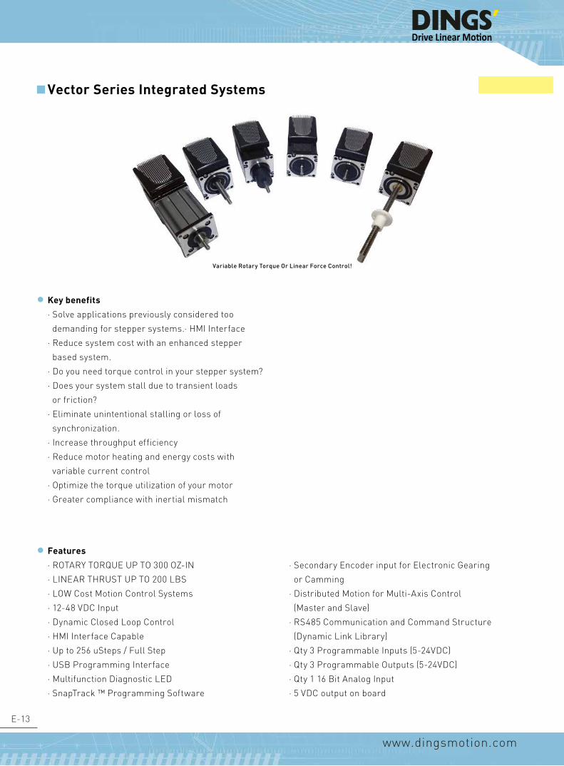
E-13
www.dingsmotion.com
Vector Series Integrated Systems
Features
· ROTARY TORQUE UP TO 300 OZ-IN
· LINEAR THRUST UP TO 200 LBS
· LOW Cost Motion Control Systems
· 12-48 VDC Input
· Dynamic Closed Loop Control
· HMI Interface Capable
· Up to 256 uSteps / Full Step
· USB Programming Interface
· Multifunction Diagnostic LED
· SnapTrack ™ Programming Software
· Secondary Encoder input for Electronic Gearing
or Camming
· Distributed Motion for Multi-Axis Control
(Master and Slave)
· RS485 Communication and Command Structure
(Dynamic Link Library)
· Qty 3 Programmable Inputs (5-24VDC)
· Qty 3 Programmable Outputs (5-24VDC)
· Qty 1 16 Bit Analog Input
· 5 VDC output on board
Key benefits
· Solve applications previously considered too
demanding for stepper systems.· HMI Interface
· Reduce system cost with an enhanced stepper
based system.
· Do you need torque control in your stepper system?
· Does your system stall due to transient loads
or friction?
· Eliminate unintentional stalling or loss of
synchronization.
· Increase throughput efficiency
· Reduce motor heating and energy costs with
variable current control
· Optimize the torque utilization of your motor
· Greater compliance with inertial mismatch
Variable Rotary Torque or Linear force Control!

E-14
www.dingsmotion.com
Product Selection Systems
1 V = Vector Series
2 Drive Option D = Drive ONLY P = ProgrammableController and Driver
3 Linear Version E = External N = Non-Captive K = Captive C = ElectricCylinder
4Motor Length
(See Speed/Force Curves)
1 = Single Stack 2 = Double Stack
5 Lead Screw Code See Table on page A-3(See Screw Lead Selection Table and Speed / Force Curves)
6 Lead ScrewLength/Stroke
XXX = length in mm(For External andNon-Captive)
XXX = x.xx inch stroke(For Captive and Kaptive)
7 Lead ScrewSurface
S = Standard / NoTeflon Coating
T = Teflon Coating
8 End Machining(see Table XX)
M = Metric U = UNC S = Smooth N = None
9 Nut Version S = Standard FreeWheeling Nut
A = Anti-Backlash Nut
NOTE: Radial (Side) Loading of The Lead Screw or Shaft Is Not Recommended!
Captive Linear Version
... Intelligence in motion
ServoTrack:™ Bridging the gap between servo, brushless DC and step motor performance.
13
DIMENSIONAL SPECIFICATIONS CAD Models Available
Electric Cylinder
Stroke Binch (mm)
Dimension A(mm)
Dimension L(mm)
0.5 (12.7) 45.7
Single stackmotor 47 mm
Double stackmotor 66 mm
0.75 (19.05 52.05
1.0 (25.4) 58.4
1.25 (31.8) 64.8
1.5 (38.1) 71.1
2.0 (50.8) 83.8
2.5 (63.5) 96.5
Non-captive Linear VesionFIRST ANGLE PROJECTION
56.25
71.4
80.6
L
15
A
B
M6 X 1.0or1/4-20 UNC
21 3 4 5 6 7
7654321
REV 00
335 Cochrane CircleMorgan Hill, CA 95037tel: 1(408)612-4970
www.kocomotionus.com
SCALE: SHEET 1 OF 1
TITLE
DWG NO.
----
02/11/2017
----
Alvin Lieu
QUALENG
MFGENG
ENG
CHECKED
DRAWN
DATEAPPROVALS
Customer
UNLESS OTHERWISE SPECIFIED:DIMENSIONS ARE IN MILLIMETERSTOLERANCES AS BELOW:
ANGLE 1
inch mm
.XXXX 0.0005
.XXX 0.005
.XX 0.01
.X 0.04
.XXX 0.013
.XX 0.13
.X 0.25
X. 1
LABEL
KOCO MOTION / DINGS' MOTION
DATE CODE
P/N REV 00
THIS DOCUMENT CONTAINS CONFIDENTIAL PROPRIETARY INFORMATION. DO NOTDISCLOSE TO OR DUPLICATE FOR OTHERS EXCEPT AS AUTHORIZED BY KOC O MOTION US, LLC.
REVISION
REV.
00
DATE ZONE DRAWN BY DESCRIPTION
08/11/2017 - INITIAL RELEASET. TREYES
CUSTOM NEMA 23VECTOR SERIES
ELECTRIC CYLINDER
P/N
NOTES:1. LABEL TO BE PLACED ON MOTOR HOUSING2. ALL MATERIALS MUST BE RoHS COMPLIANT
ParametersVoltage(V)Current (A)
Resistance (Ohms)Inductance (mH)
Step AngleScrew Lead
Customer Approval:Signature:
Date:
FIRST ANGLE PROJECTION
38.1 ±0.05
56.2
47.1 ±0.25
4X 5.1 THRU
71.4
152.4 ±1
45 ±0.6 1.5 ±0.2
80.6
M6 X 1.0or1/4-20 UNC
21 3 4 5 6 7 8
A
B
C
D
E E
D
C
B
A
335 Cochrane CircleMorgan Hill, CA 95037tel: 1(408)612-4970
www.kocomotionus.comCustomer
THIS DOCUMENT CONTAINS CONFIDENTIAL PROPRIETARY INFORMATION. DO NOTDISCLOSE TO OR DUPLICATE FOR OTHERS EXCEPT AS AUTHORIZED BY KOC O MOTION US, LLC.
REVISION
REV.
00
DATE ZONE DRAWN BY DESCRIPTION
02/11/2017 - INITIAL RELEASEA. LIEUNOTES:1. LABEL TO BE PLACED ON MOTOR HOUSING2. ALL MATERIALS MUST BE RoHS COMPLIANT3. SCREW LEAD: "Q" LEAD,(4.8768mm/ 0.192")4. 5. ASSEMBLY WITH ANTI-BACKLASH NUT
ParametersVoltage(V)Current (A)
Resistance (Ohms)Inductance (mH)
Step AngleScrew Lead
Customer Approval:
5.01.8
5.05.05.05.0
Stroke Specification
Stroke Binch (mm)
A (mm)
Dimension L(mm)
0.50 (12.70) 45.70
Single StackMotor 47 mm
Double StackMotor 66 mm
0.75 (19.05) 52.05
1.00 (25.40) 58.40
1.25 (31.80) 64.80
1.50 (38.10) 71.10
2.00 (50.80) 83.80
2.50 (63.50) 96.50

E-15
www.dingsmotion.com
External Linear Vesion
Stroke A (mm)
B (mm)
Single Stack Motor Length L= 45mm
Double Stack Motor Length L= 65mm
Max Lead Screw Rear Extention (fully Retracted) C(mm)12.70 23.30 0 019.05 29.65 0 025.40 36.00 0 031.75 42.35 0 038.10 48.70 6 050.80 61.40 18.7 8.763.50 74.10 31.4 21.4
... Intelligence in motion
ServoTrack:™ Bridging the gap between servo, brushless DC and step motor performance.
13
DIMENSIONAL SPECIFICATIONS CAD Models Available
Electric Cylinder
Stroke Binch (mm)
Dimension A(mm)
Dimension L(mm)
0.5 (12.7) 45.7
Single stackmotor 47 mm
Double stackmotor 66 mm
0.75 (19.05 52.05
1.0 (25.4) 58.4
1.25 (31.8) 64.8
1.5 (38.1) 71.1
2.0 (50.8) 83.8
2.5 (63.5) 96.5
Non-captive Linear VesionFIRST ANGLE PROJECTION
56.25
71.4
80.6
L
15
A
B
M6 X 1.0or1/4-20 UNC
21 3 4 5 6 7
7654321
REV 00
335 Cochrane CircleMorgan Hill, CA 95037tel: 1(408)612-4970
www.kocomotionus.com
SCALE: SHEET 1 OF 1
TITLE
DWG NO.
----
02/11/2017
----
Alvin Lieu
QUALENG
MFGENG
ENG
CHECKED
DRAWN
DATEAPPROVALS
Customer
UNLESS OTHERWISE SPECIFIED:DIMENSIONS ARE IN MILLIMETERSTOLERANCES AS BELOW:
ANGLE 1
inch mm
.XXXX 0.0005
.XXX 0.005
.XX 0.01
.X 0.04
.XXX 0.013
.XX 0.13
.X 0.25
X. 1
LABEL
KOCO MOTION / DINGS' MOTION
DATE CODE
P/N REV 00
THIS DOCUMENT CONTAINS CONFIDENTIAL PROPRIETARY INFORMATION. DO NOTDISCLOSE TO OR DUPLICATE FOR OTHERS EXCEPT AS AUTHORIZED BY KOC O MOTION US, LLC.
REVISION
REV.
00
DATE ZONE DRAWN BY DESCRIPTION
08/11/2017 - INITIAL RELEASET. TREYES
CUSTOM NEMA 23VECTOR SERIES
ELECTRIC CYLINDER
P/N
NOTES:1. LABEL TO BE PLACED ON MOTOR HOUSING2. ALL MATERIALS MUST BE RoHS COMPLIANT
ParametersVoltage(V)Current (A)
Resistance (Ohms)Inductance (mH)
Step AngleScrew Lead
Customer Approval:Signature:
Date:
FIRST ANGLE PROJECTION
38.1 ±0.05
56.2
47.1 ±0.25
4X 5.1 THRU
71.4
152.4 ±1
45 ±0.6 1.5 ±0.2
80.6
M6 X 1.0or1/4-20 UNC
21 3 4 5 6 7 8
A
B
C
D
E E
D
C
B
A
335 Cochrane CircleMorgan Hill, CA 95037tel: 1(408)612-4970
www.kocomotionus.comCustomer
THIS DOCUMENT CONTAINS CONFIDENTIAL PROPRIETARY INFORMATION. DO NOTDISCLOSE TO OR DUPLICATE FOR OTHERS EXCEPT AS AUTHORIZED BY KOC O MOTION US, LLC.
REVISION
REV.
00
DATE ZONE DRAWN BY DESCRIPTION
02/11/2017 - INITIAL RELEASEA. LIEUNOTES:1. LABEL TO BE PLACED ON MOTOR HOUSING2. ALL MATERIALS MUST BE RoHS COMPLIANT3. SCREW LEAD: "Q" LEAD,(4.8768mm/ 0.192")4. 5. ASSEMBLY WITH ANTI-BACKLASH NUT
ParametersVoltage(V)Current (A)
Resistance (Ohms)Inductance (mH)
Step AngleScrew Lead
Customer Approval:
5.01.8
5.05.05.05.0
14
External Linear Vesion
Captive Linear Version
DIMENSIONAL SPECIFICATIONS continued
FIRST ANGLE PROJECTION
38.1 ±0.05
56.2
47.1 ±0.25
71.4
45 ±0.6 1.5 ±0.2
152.4 1 80.6
31.7
3X 3.50 THRUON 22.2mm
4.8
25.4
15.88
21 3 4 5 6 7 8
87654321
A
B
C
D
E
F
REV 00
335 Cochrane CircleMorgan Hill, CA 95037tel: 1(408)612-4970
www.kocomotionus.com
SCALE: SHEET 1 OF 1
TITLE
DWG NO.
----
02/11/2017
----
Tim Treyes
QUALENG
MFGENG
ENG
CHECKED
DRAWN
DATEAPPROVALS
Customer
UNLESS OTHERWISE SPECIFIED:DIMENSIONS ARE IN MILLIMETERSTOLERANCES AS BELOW:
ANGLE 1
inch mm
.XXXX 0.0005
.XXX 0.005
.XX 0.01
.X 0.04
.XXX 0.013
.XX 0.13
.X 0.25
X. 1
LABEL
KOCO MOTION / DINGS' MOTION
DATE CODE
P/N REV 00
THIS DOCUMENT CONTAINS CONFIDENTIAL PROPRIETARY INFORMATION. DO NOTDISCLOSE TO OR DUPLICATE FOR OTHERS EXCEPT AS AUTHORIZED BY KOC O MOTION US, LLC.
REVISION
REV.
00
DATE ZONE DRAWN BY DESCRIPTION
08/14/2017 - INITIAL RELEASET. TREYES
CUSTOM NEMA 23 ExternalLinear ActuatorVector Series
P/N
NOTES:1. LABEL TO BE PLACED ON MOTOR HOUSING2. ALL MATERIALS MUST BE RoHS COMPLIANT3. VECTOR SERIES EXTERNAL
ParametersVoltage(V)Current (A)
Resistance (Ohms)Inductance (mH)
Step AngleScrew Lead
Customer Approval:Signature:
Date:
5.01.8
5.05.05.05.0
FIRST ANGLE PROJECTION
56.25
47.1 ±0.25
38.10 ±0.05
4X M4 THRU
71.4
1.50
28
L B
101.11
27.7 ±1
12
3
80.6
15
A C
M6 X1.0OR
1/4-20 UNC
9.5
ITEM QTY P/N MANUFACTURER DESCRIPTION1 1 P23C2130W4-63.5SMSER2-M01 DINGS' ST484 READY - NEMA 23 CAPTIVE LINEAR2 1 301-004-563S-P93-B10 ANDON ELECTRONICS CORP. (4) PIN RIGHT ANGLE SNAP SIP SOCKET HEADS
Stroke A (mm) B (mm)
Single Stack Motor Length L= 45mm
Double Stack Motor Length L= 65mm
Max Lead Screw Rear Extention (Fully Retracted)
C(mm)
12.7 23.3 0 019.05 29.65 0 025.4 36 0 031.75 42.35 0 038.1 48.7 6 050.8 61.4 18.7 8.763.5 74.1 31.4 21.4
21 3 4 5 6 7 8
87654321
A
B
C
D
E
F F
E
D
C
B
A
REV 00
335 Cochrane CircleMorgan Hill, CA 95037tel: 1(408)612-4970
www.kocomotionus.com
SCALE: SHEET 1 OF 1
TITLE
DWG NO.
----
08/10/2017
----
Tim Treyes
QUALENG
MFGENG
ENG
CHECKED
DRAWN
DATEAPPROVALS
Customer
UNLESS OTHERWISE SPECIFIED:DIMENSIONS ARE IN MILLIMETERSTOLERANCES AS BELOW:
ANGLE 1
inch mm
.XXXX 0.0005
.XXX 0.005
.XX 0.01
.X 0.04
.XXX 0.013
.XX 0.13
.X 0.25
X. 1
LABEL
KOCO MOTION / DINGS' MOTION
DATE CODE
P23K2130xx4-63.5SMSER2-001 REV 00
THIS DOCUMENT CONTAINS CONFIDENTIAL PROPRIETARY INFORMATION. DO NOTDISCLOSE TO OR DUPLICATE FOR OTHERS EXCEPT AS AUTHORIZED BY KOC O MOTION US, LLC.
REVISION
REV.
00
DATE ZONE DRAWN BY DESCRIPTION
08/10/2017 - INITIAL RELEASET. TREYES
CUSTOM NEMA 23 Captive Linear Actuator ST484 Ready
P23K2130xx4-63.5SMSER2-M01
NOTES:
1. LABEL TO BE PLACED ON MOTOR HOUSING 2. ALL MATERIALS MUST BE RoHS COMPLIANT 4. SERVOTRACK VECTOR MOTOR PACKAGE
ParametersVoltage(V)Current (A)
Resistance (Ohms)Inductance (mH)
Step AngleScrew Lead -
1.8
1.70.73.02.1
14
External Linear Vesion
Captive Linear Version
DIMENSIONAL SPECIFICATIONS continued
FIRST ANGLE PROJECTION
38.1 ±0.05
56.2
47.1 ±0.25
71.4
45 ±0.6 1.5 ±0.2
152.4 1 80.6
31.7
3X 3.50 THRUON 22.2mm
4.8
25.4 15.88
21 3 4 5 6 7 8
87654321
A
B
C
D
E
F
REV 00
335 Cochrane CircleMorgan Hill, CA 95037tel: 1(408)612-4970
www.kocomotionus.com
SCALE: SHEET 1 OF 1
TITLE
DWG NO.
----
02/11/2017
----
Tim Treyes
QUALENG
MFGENG
ENG
CHECKED
DRAWN
DATEAPPROVALS
Customer
UNLESS OTHERWISE SPECIFIED:DIMENSIONS ARE IN MILLIMETERSTOLERANCES AS BELOW:
ANGLE 1
inch mm
.XXXX 0.0005
.XXX 0.005
.XX 0.01
.X 0.04
.XXX 0.013
.XX 0.13
.X 0.25
X. 1
LABEL
KOCO MOTION / DINGS' MOTION
DATE CODE
P/N REV 00
THIS DOCUMENT CONTAINS CONFIDENTIAL PROPRIETARY INFORMATION. DO NOTDISCLOSE TO OR DUPLICATE FOR OTHERS EXCEPT AS AUTHORIZED BY KOC O MOTION US, LLC.
REVISION
REV.
00
DATE ZONE DRAWN BY DESCRIPTION
08/14/2017 - INITIAL RELEASET. TREYES
CUSTOM NEMA 23 ExternalLinear ActuatorVector Series
P/N
NOTES:1. LABEL TO BE PLACED ON MOTOR HOUSING2. ALL MATERIALS MUST BE RoHS COMPLIANT3. VECTOR SERIES EXTERNAL
ParametersVoltage(V)Current (A)
Resistance (Ohms)Inductance (mH)
Step AngleScrew Lead
Customer Approval:Signature:
Date:
5.01.8
5.05.05.05.0
FIRST ANGLE PROJECTION
56.25
47.1 ±0.25
38.10 ±0.05
4X M4 THRU
71.4
1.50
28
L B
101.11
27.7 ±1
12
3
80.6
15
A C
M6 X1.0OR
1/4-20 UNC
9.5
ITEM QTY P/N MANUFACTURER DESCRIPTION1 1 P23C2130W4-63.5SMSER2-M01 DINGS' ST484 READY - NEMA 23 CAPTIVE LINEAR2 1 301-004-563S-P93-B10 ANDON ELECTRONICS CORP. (4) PIN RIGHT ANGLE SNAP SIP SOCKET HEADS
Stroke A (mm) B (mm)
Single Stack Motor Length L= 45mm
Double Stack Motor Length L= 65mm
Max Lead Screw Rear Extention (Fully Retracted)
C(mm)
12.7 23.3 0 019.05 29.65 0 025.4 36 0 031.75 42.35 0 038.1 48.7 6 050.8 61.4 18.7 8.763.5 74.1 31.4 21.4
21 3 4 5 6 7 8
87654321
A
B
C
D
E
F F
E
D
C
B
A
REV 00
335 Cochrane CircleMorgan Hill, CA 95037tel: 1(408)612-4970
www.kocomotionus.com
SCALE: SHEET 1 OF 1
TITLE
DWG NO.
----
08/10/2017
----
Tim Treyes
QUALENG
MFGENG
ENG
CHECKED
DRAWN
DATEAPPROVALS
Customer
UNLESS OTHERWISE SPECIFIED:DIMENSIONS ARE IN MILLIMETERSTOLERANCES AS BELOW:
ANGLE 1
inch mm
.XXXX 0.0005
.XXX 0.005
.XX 0.01
.X 0.04
.XXX 0.013
.XX 0.13
.X 0.25
X. 1
LABEL
KOCO MOTION / DINGS' MOTION
DATE CODE
P23K2130xx4-63.5SMSER2-001 REV 00
THIS DOCUMENT CONTAINS CONFIDENTIAL PROPRIETARY INFORMATION. DO NOTDISCLOSE TO OR DUPLICATE FOR OTHERS EXCEPT AS AUTHORIZED BY KOC O MOTION US, LLC.
REVISION
REV.
00
DATE ZONE DRAWN BY DESCRIPTION
08/10/2017 - INITIAL RELEASET. TREYES
CUSTOM NEMA 23 Captive Linear Actuator ST484 Ready
P23K2130xx4-63.5SMSER2-M01
NOTES:
1. LABEL TO BE PLACED ON MOTOR HOUSING 2. ALL MATERIALS MUST BE RoHS COMPLIANT 4. SERVOTRACK VECTOR MOTOR PACKAGE
ParametersVoltage(V)Current (A)
Resistance (Ohms)Inductance (mH)
Step AngleScrew Lead -
1.8
1.70.73.02.1
14
External Linear Vesion
Captive Linear Version
DIMENSIONAL SPECIFICATIONS continued
FIRST ANGLE PROJECTION
38.1 ±0.05
56.2
47.1 ±0.25
71.4
45 ±0.6 1.5 ±0.2
152.4 1 80.6
31.7
3X 3.50 THRUON 22.2mm
4.8
25.4
15.88
21 3 4 5 6 7 8
87654321
A
B
C
D
E
F
REV 00
335 Cochrane CircleMorgan Hill, CA 95037tel: 1(408)612-4970
www.kocomotionus.com
SCALE: SHEET 1 OF 1
TITLE
DWG NO.
----
02/11/2017
----
Tim Treyes
QUALENG
MFGENG
ENG
CHECKED
DRAWN
DATEAPPROVALS
Customer
UNLESS OTHERWISE SPECIFIED:DIMENSIONS ARE IN MILLIMETERSTOLERANCES AS BELOW:
ANGLE 1
inch mm
.XXXX 0.0005
.XXX 0.005
.XX 0.01
.X 0.04
.XXX 0.013
.XX 0.13
.X 0.25
X. 1
LABEL
KOCO MOTION / DINGS' MOTION
DATE CODE
P/N REV 00
THIS DOCUMENT CONTAINS CONFIDENTIAL PROPRIETARY INFORMATION. DO NOTDISCLOSE TO OR DUPLICATE FOR OTHERS EXCEPT AS AUTHORIZED BY KOC O MOTION US, LLC.
REVISION
REV.
00
DATE ZONE DRAWN BY DESCRIPTION
08/14/2017 - INITIAL RELEASET. TREYES
CUSTOM NEMA 23 ExternalLinear ActuatorVector Series
P/N
NOTES:1. LABEL TO BE PLACED ON MOTOR HOUSING2. ALL MATERIALS MUST BE RoHS COMPLIANT3. VECTOR SERIES EXTERNAL
ParametersVoltage(V)Current (A)
Resistance (Ohms)Inductance (mH)
Step AngleScrew Lead
Customer Approval:Signature:
Date:
5.01.8
5.05.05.05.0
FIRST ANGLE PROJECTION
56.25
47.1 ±0.25
38.10 ±0.05
4X M4 THRU
71.4
1.50
28
L B
101.11
27.7 ±1
12
3
80.6
15
A C
M6 X1.0OR
1/4-20 UNC
9.5
ITEM QTY P/N MANUFACTURER DESCRIPTION1 1 P23C2130W4-63.5SMSER2-M01 DINGS' ST484 READY - NEMA 23 CAPTIVE LINEAR2 1 301-004-563S-P93-B10 ANDON ELECTRONICS CORP. (4) PIN RIGHT ANGLE SNAP SIP SOCKET HEADS
Stroke A (mm) B (mm)
Single Stack Motor Length L= 45mm
Double Stack Motor Length L= 65mm
Max Lead Screw Rear Extention (Fully Retracted)
C(mm)
12.7 23.3 0 019.05 29.65 0 025.4 36 0 031.75 42.35 0 038.1 48.7 6 050.8 61.4 18.7 8.763.5 74.1 31.4 21.4
21 3 4 5 6 7 8
87654321
A
B
C
D
E
F F
E
D
C
B
A
REV 00
335 Cochrane CircleMorgan Hill, CA 95037tel: 1(408)612-4970
www.kocomotionus.com
SCALE: SHEET 1 OF 1
TITLE
DWG NO.
----
08/10/2017
----
Tim Treyes
QUALENG
MFGENG
ENG
CHECKED
DRAWN
DATEAPPROVALS
Customer
UNLESS OTHERWISE SPECIFIED:DIMENSIONS ARE IN MILLIMETERSTOLERANCES AS BELOW:
ANGLE 1
inch mm
.XXXX 0.0005
.XXX 0.005
.XX 0.01
.X 0.04
.XXX 0.013
.XX 0.13
.X 0.25
X. 1
LABEL
KOCO MOTION / DINGS' MOTION
DATE CODE
P23K2130xx4-63.5SMSER2-001 REV 00
THIS DOCUMENT CONTAINS CONFIDENTIAL PROPRIETARY INFORMATION. DO NOTDISCLOSE TO OR DUPLICATE FOR OTHERS EXCEPT AS AUTHORIZED BY KOC O MOTION US, LLC.
REVISION
REV.
00
DATE ZONE DRAWN BY DESCRIPTION
08/10/2017 - INITIAL RELEASET. TREYES
CUSTOM NEMA 23 Captive Linear Actuator ST484 Ready
P23K2130xx4-63.5SMSER2-M01
NOTES:
1. LABEL TO BE PLACED ON MOTOR HOUSING 2. ALL MATERIALS MUST BE RoHS COMPLIANT 4. SERVOTRACK VECTOR MOTOR PACKAGE
ParametersVoltage(V)Current (A)
Resistance (Ohms)Inductance (mH)
Step AngleScrew Lead -
1.8
1.70.73.02.1
Kaptive Linear Version
Stroke Specification
Non-captive Linear Vesion

E-16
www.dingsmotion.com
EXAMPLES
VP23H-45
VP23H-55-GR
VP23H-75-PG10
VP23H-45-XXX-001 = Custom Suffix
Product Selection Systems
1 V Vector Series
2 P Programmable Controller with Driver
3 23 Nema Size
4 H Rotary Version
5Motor Selection:
(See Speed /Torque Curves)
-45 = 0.8 Nm Torque Motor-55 = 1.2 Nm Torque Motor-75 = 2.0 Nm Torque Motor
6 -GR Gearbox Ready
7 -PG10 Planetary Gearbox (10:1 Ratio)
8 -XYZ Custom Suffix
... Intelligence in motion
ServoTrack:™ Bridging the gap between servo, brushless DC and step motor performance.
15
Rotary Versions -45 Option
-55 Option
FIRST ANGLE PROJECTION
57.2
38.1 -0 0.05
47.14 ±0.25
4X M4THRU
15
45 ±0.6 1.6 ±0.25
6.35
15
5.8
36
71.4
80.6 PWR
GND
DB15 CONNECTOR
MiniUSB
21 3 4 5 6 7 8
87654321
A
B
C
D
E
F F
E
D
C
B
A
REV 00
335 Cochrane CircleMorgan Hill, CA 95037tel: 1(408)612-4970
www.kocomotionus.com
SCALE: SHEET 1 OF 1
TITLE
DWG NO.
----
08/30/2017
----
Tim Treyes
QUALENG
MFGENG
ENG
CHECKED
DRAWN
DATEAPPROVALS
Customer
UNLESS OTHERWISE SPECIFIED:DIMENSIONS ARE IN MILLIMETERSTOLERANCES AS BELOW:
ANGLE 1
inch mm
.XXXX 0.0005
.XXX 0.005
.XX 0.01
.X 0.04
.XXX 0.013
.XX 0.13
.X 0.25
X. 1
LABEL
KOCO MOTION / DINGS' MOTION
DATE CODE
P/N REV 00
THIS DOCUMENT CONTAINS CONFIDENTIAL PROPRIETARY INFORMATION. DO NOTDISCLOSE TO OR DUPLICATE FOR OTHERS EXCEPT AS AUTHORIZED BY KOC O MOTION US, LLC.
REVISION
REV.
00
DATE ZONE DRAWN BY DESCRIPTION
08/30/2017 - INITIAL RELEASET. TREYES
VECTOR SERIESNEMA 23 SINGLE-STACKEDROTARY STEPPER MOTOR
P/N
NOTES:1. LABEL TO BE PLACED ON MOTOR HOUSING2. ALL MATERIALS MUST BE RoHS COMPLIANT
ParametersVoltage(V)Current (A)
Resistance (Ohms)Inductance (mH)
Step AngleScrew Lead
Customer Approval:Signature:
Date:
5.01.8
5.05.05.05.0
FIRST ANGLE PROJECTION
PWR
GND
DB15 CONNECTOR
MiniUSB
71.4
15
36 55 ±0.6 1.6 0.25
15
6.35
5.85
80.62
21 3 4 5 6 7 8
87654321
A
B
C
D
E
F F
E
D
C
B
A
REV 00
335 Cochrane CircleMorgan Hill, CA 95037tel: 1(408)612-4970
www.kocomotionus.com
SCALE: SHEET 1 OF 1
TITLE
DWG NO.
----
08/29/2017
----
Tim Treyes
QUALENG
MFGENG
ENG
CHECKED
DRAWN
DATEAPPROVALS
Customer
UNLESS OTHERWISE SPECIFIED:DIMENSIONS ARE IN MILLIMETERSTOLERANCES AS BELOW:
ANGLE 1
inch mm
.XXXX 0.0005
.XXX 0.005
.XX 0.01
.X 0.04
.XXX 0.013
.XX 0.13
.X 0.25
X. 1
LABEL
KOCO MOTION / DINGS' MOTION
DATE CODE
P/N REV 00
THIS DOCUMENT CONTAINS CONFIDENTIAL PROPRIETARY INFORMATION. DO NOTDISCLOSE TO OR DUPLICATE FOR OTHERS EXCEPT AS AUTHORIZED BY KOC O MOTION US, LLC.
REVISION
REV.
00
DATE ZONE DRAWN BY DESCRIPTION
08/29/2017 - INITIAL RELEASET. TREYES
VECTOR SERIESNEMA 23 DOUBLE-STACKEDROTARY STEPPER MOTOR
P/N
NOTES:1. LABEL TO BE PLACED ON MOTOR HOUSING2. ALL MATERIALS MUST BE RoHS COMPLIANT
ParametersVoltage(V)Current (A)
Resistance (Ohms)Inductance (mH)
Step AngleScrew Lead
Customer Approval:Signature:
Date:
5.01.8
5.05.05.05.0
Rotary Versions45 Option
... Intelligence in motion
ServoTrack:™ Bridging the gap between servo, brushless DC and step motor performance.
15
Rotary Versions -45 Option
-55 Option
FIRST ANGLE PROJECTION
57.2
38.1 -0 0.05
47.14 ±0.25
4X M4THRU
15
45 ±0.6 1.6 ±0.25
6.35
15
5.8
36
71.4
80.6 PWR
GND
DB15 CONNECTOR
MiniUSB
21 3 4 5 6 7 8
87654321
A
B
C
D
E
F F
E
D
C
B
A
REV 00
335 Cochrane CircleMorgan Hill, CA 95037tel: 1(408)612-4970
www.kocomotionus.com
SCALE: SHEET 1 OF 1
TITLE
DWG NO.
----
08/30/2017
----
Tim Treyes
QUALENG
MFGENG
ENG
CHECKED
DRAWN
DATEAPPROVALS
Customer
UNLESS OTHERWISE SPECIFIED:DIMENSIONS ARE IN MILLIMETERSTOLERANCES AS BELOW:
ANGLE 1
inch mm
.XXXX 0.0005
.XXX 0.005
.XX 0.01
.X 0.04
.XXX 0.013
.XX 0.13
.X 0.25
X. 1
LABEL
KOCO MOTION / DINGS' MOTION
DATE CODE
P/N REV 00
THIS DOCUMENT CONTAINS CONFIDENTIAL PROPRIETARY INFORMATION. DO NOTDISCLOSE TO OR DUPLICATE FOR OTHERS EXCEPT AS AUTHORIZED BY KOC O MOTION US, LLC.
REVISION
REV.
00
DATE ZONE DRAWN BY DESCRIPTION
08/30/2017 - INITIAL RELEASET. TREYES
VECTOR SERIESNEMA 23 SINGLE-STACKEDROTARY STEPPER MOTOR
P/N
NOTES:1. LABEL TO BE PLACED ON MOTOR HOUSING2. ALL MATERIALS MUST BE RoHS COMPLIANT
ParametersVoltage(V)Current (A)
Resistance (Ohms)Inductance (mH)
Step AngleScrew Lead
Customer Approval:Signature:
Date:
5.01.8
5.05.05.05.0
FIRST ANGLE PROJECTION
PWR
GND
DB15 CONNECTOR
MiniUSB
71.4
15
36 55 ±0.6 1.6 0.25
15
6.35
5.85
80.62
21 3 4 5 6 7 8
87654321
A
B
C
D
E
F F
E
D
C
B
A
REV 00
335 Cochrane CircleMorgan Hill, CA 95037tel: 1(408)612-4970
www.kocomotionus.com
SCALE: SHEET 1 OF 1
TITLE
DWG NO.
----
08/29/2017
----
Tim Treyes
QUALENG
MFGENG
ENG
CHECKED
DRAWN
DATEAPPROVALS
Customer
UNLESS OTHERWISE SPECIFIED:DIMENSIONS ARE IN MILLIMETERSTOLERANCES AS BELOW:
ANGLE 1
inch mm
.XXXX 0.0005
.XXX 0.005
.XX 0.01
.X 0.04
.XXX 0.013
.XX 0.13
.X 0.25
X. 1
LABEL
KOCO MOTION / DINGS' MOTION
DATE CODE
P/N REV 00
THIS DOCUMENT CONTAINS CONFIDENTIAL PROPRIETARY INFORMATION. DO NOTDISCLOSE TO OR DUPLICATE FOR OTHERS EXCEPT AS AUTHORIZED BY KOC O MOTION US, LLC.
REVISION
REV.
00
DATE ZONE DRAWN BY DESCRIPTION
08/29/2017 - INITIAL RELEASET. TREYES
VECTOR SERIESNEMA 23 DOUBLE-STACKEDROTARY STEPPER MOTOR
P/N
NOTES:1. LABEL TO BE PLACED ON MOTOR HOUSING2. ALL MATERIALS MUST BE RoHS COMPLIANT
ParametersVoltage(V)Current (A)
Resistance (Ohms)Inductance (mH)
Step AngleScrew Lead
Customer Approval:Signature:
Date:
5.01.8
5.05.05.05.0
55 Option

E-17
www.dingsmotion.com
www.kocomotionus.com
ServoTrack™ Vector23 Integrated Motion Systems
16
-75 Option
DB15 Connector Designations
Pin# Function
1 General Purpose Output #1 +
2 General Purpose Output #2 +
3 +5VDC Out
4 Rx
5 General Purpose Input #1 (OR Secondary Encoder Input, Single Ended)
6 General Purpose Output #1-
7 General Purpose Output #2 -
8 General Purpose Output #3 +
9 N/A
10 Tx
11 General Purpose Input #2 (Or Secondary Encoder Input, Single Ended)
12 General Purpose Output #3 -
13 General Purpose Input #2
14 GND
15 Analog Input
DB15 Connector
FIRST ANGLE PROJECTION
71.4
36
15
76 ±0.6
15
5.8
6.35
1.6 ±0.25
80.6
21 3 4 5 6 7 8
87654321
A
B
C
D
E
F F
E
D
C
B
A
REV 00
335 Cochrane CircleMorgan Hill, CA 95037tel: 1(408)612-4970
www.kocomotionus.com
SCALE: SHEET 1 OF 1
TITLE
DWG NO.
----
08/30/2017
----
Tim Treyes
QUALENG
MFGENG
ENG
CHECKED
DRAWN
DATEAPPROVALS
Customer
UNLESS OTHERWISE SPECIFIED:DIMENSIONS ARE IN MILLIMETERSTOLERANCES AS BELOW:
ANGLE 1
inch mm
.XXXX 0.0005
.XXX 0.005
.XX 0.01
.X 0.04
.XXX 0.013
.XX 0.13
.X 0.25
X. 1
LABEL
KOCO MOTION / DINGS' MOTION
DATE CODE
P/N REV 00
THIS DOCUMENT CONTAINS CONFIDENTIAL PROPRIETARY INFORMATION. DO NOTDISCLOSE TO OR DUPLICATE FOR OTHERS EXCEPT AS AUTHORIZED BY KOC O MOTION US, LLC.
REVISION
REV.
00
DATE ZONE DRAWN BY DESCRIPTION
08/30/2017 - INITIAL RELEASET. TREYES
VECTOR SERIESNEMA 23 TRIPLE-STACKEDROTARY STEPPER MOTOR
P/N
NOTES:1. LABEL TO BE PLACED ON MOTOR HOUSING2. ALL MATERIALS MUST BE RoHS COMPLIANT
ParametersVoltage(V)Current (A)
Resistance (Ohms)Inductance (mH)
Step AngleScrew Lead
Customer Approval:Signature:
Date:
5.01.8
5.05.05.05.0
NOTE: We recommend purchasing the breakout board (Part #VBB-1) on page 17.
NOTE: Using pins 5 and 11 for a secondary encoder input will reduce the number of inputs down to one.
VBB-1 BREAKOUT BOARD
DB15 Pin Breakout BoardFor Rapid Prototyping
The optional breakout board is ideal for rapid prototyping and proof of concept designs. The breakout board may be plugged directy into into the Vector unit.
Signals are accessed via a pluggable 15-pin Phoenix clamp-type terminal connector.
75 Option
17
VBB-1 BREAKOUT BOARD
DB15 Pin Breakout Board For Rapid PrototypingThe optional breakout board is ideal for rapid prototyping and proof of concept designs. The breakout board may be plugged directy into into the Vector unit.
Signals are accessed via a pluggable 15-pin Phoenix clamp-type terminal connector.
NOTE: Please reference the complete hardware and Snaptrack™ software manuals at our website:

E-18
www.dingsmotion.com
DS-CL28-SA Integrated Closed-loop Drive
SummarizeClosed-loop stepper motor integration. At the end of motor, drive and controller package with 16,000 PPR encoder integrated. Including high resolution encoder, every 25ms update the motor position in real time. Integrated motion control through the RS485 communication to the computer, also can be connected 16 axes at the same time. All of the moving conditions are performed by a parameter saved in the FLASHROM. The movement library (DLL) provides the maximum 64-bit program of Windows2000 / XP, can be save in FLASHROM memory.
Feature1. Based on the network control can be through RS-485 & PC connection .All motion parameters are stored in the FLASH ROM.The maximum can be connected to 16-axes.
2. Closed loop controller system-integration with high resolution encoder, Each 25ms updates the motor position in real time.
3. High torque, High rotate speed compare with ordinary motor, can make the motor at running 100% working condition without losing step.
Torque
DS-CL28-SA
Speed
Stepping
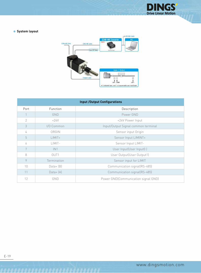
E-19
www.dingsmotion.com
System layout
Input /Output Configurations
Port Function Description
1 GND Power GND
2 +24V +24V Power Input
3 I/O Common Input/Output Signal common terminal
4 ORGIN Sensor input Origin
5 LIMIT+ Sensor Input LIMINT+
6 LIMIT- Sensor Input LIMIT-
7 IN1 User Input(User Input0 )
8 OUT1 User Output(User Output1)
9 Termination Sensor input for LIMIT
10 Data+ (B) Communication signal(RS-485)
11 Data+ (A) Communication signal(RS-485)
12 GND Power GND(Communication signal GND)

E-20
www.dingsmotion.com
Dimension
CUSTOMERWIRING CHART EXCITING SEQUENCE
NOTICE TO PERSONS RECEIVING THIS DRAWING THIS DRAWING IS ONLY CONDITIONALLY ISSUED, AND FOR THE SOLE PURPOSE OF INFORMING LICENSEES AND ASSOCIATE CONTRACTORS OF DINGS' MOTION, AND VENDORS THERETO AND CUSTOMERS THEREOF, RECEIPT OR POCESSION THEREOF DOES NOT CONFER TO TRANSFER ANY RIGHT IN THE SUBJECT MATTER OF THE DRAWING. THE DESIGN, CONSTRUCTION, TECHNICAL INFORMATION AND ALL OTHER SUBJECT MATTER SHOWN IN THIS DRAWING ARE AND REMAIN, EXCEPT AS MAY BE OTHERWISE INDICATED BY WRITTEN NOTICE HEREON, THE EXCLUSIVE PROPERTY OF SAID CORPORATION. THIS DRAWING MAY BE REPRODUCED ONLY BY LICENSEES AND ASSOCIATE CONTRACTORS OF SAID CORPORATION AND ONLY FOR LICENSED MANUFACTURE, AND BY VENDORS MANUFACTURING FOR SAID CORPORATION AND ONLY FOR LICENSEES AND ASSOCIATECONTRACTORS.
UNLESS OTHERWISE SPECIFIED ALL DIMENSIONS ARE IN MILLIMETERS AND TOLERANCES ARE AS BELOW PER ISO2768-cK.
LINEAR ANGLUR0~3
3~6
6~30
30~120
±0.2
±0.5
±0.8
±1.5
0~10
10~50
50~120
120~400
±1.5°
±1°
±30’
±15’
DRAWN DATE
DATEAPPRVD
SIZE
SCALE
A3
1:1
SHEET
REV 00CCW
CWRed A+
Red/wht A-
Grn B+Grn/wht B-
+-
+
+
+ -
-
-
HC
1 OF 1
2017/3/16
MODEL DMB0804-45A-11E2210-001
B+ B-
MA+
A-
REVISIONREV. DATE DESCRIPTION DRAWN BY
KSS
�bsolute encoder
1.50.2L0.5
34
24 19 4-M2.52.5min
230.15
28
22 - 0.050+
151002
REVISION
REV. DATE DESCRIPTION DRAWN BY
D
E
F
C C
D
Linear Actuator
常州市鼎智机电有限公司DINGS' MOTION
MFG'D 工艺
TITLE:
DATE 日期 线性步进电机
技术规格书SpecificationUNLESS OTHERWISE SPECIFIED:
其余未注事项:
尺寸单位为毫米(mm).
未注公差按以下标准:
毫米 mm英寸 inch
客户 Customer
Checkd 审核
Name 姓名
APPV'D 批准QA 质量
DRAWN 设计
角度 ±1°
视图 重要尺寸 ▲
何超
L 0.5
1.5 0.2
100 2
32020
4 leads
AWG #26
4-M2.5 2.5Min
6
23 0.15
28
19.1
3- 3.2
12.7
9.5
8
220 0.05
3.2
Specifications
Item Description
Input Voltage 24VDC±10%
Control Method Closed loop control with 32bit DSP
Multi Axes Driver Max 16 axes through daisy-chain
Position table 64 motion command steps
Current Consumption Max 500mA (Except motor current)
Ambient Temperature
Use:0~55℃Storage:-20~70℃
Humidity Use:35~85%RHStorage:10~90%RH
Vibration Resist 0.5G
Rotation Speed 0~3000rpm
Resolution(P/R) Max 16000PPR
Protection Functions 13 Protection Functions (over Current, overload etc)
Rotational Direction CW/CCW(Selectable by parameter)
Input Signal LIMIT+, LIMIT-, ORIGIN,1 programmable input(optocoupler)
Output Signal 1 programmable Output
Communication interface RS-485 Serial communication with PCTransmission speed: 9600~921600(bps)
Position Control
Incremental modeData range: -134217727 to +134217727(pulse)
Pules speed: Max 500(kpps)
Return to Origin Origin sensor, ±Limit sensor, 2 Phase
GUI User interface program within windows
Software Motion library(DLL) for windows 2000/XP/7/8/10
CUSTOMERWIRING CHART EXCITING SEQUENCE
NOTICE TO PERSONS RECEIVING THIS DRAWING THIS DRAWING IS ONLY CONDITIONALLY ISSUED, AND FOR THE SOLE PURPOSE OF INFORMING LICENSEES AND ASSOCIATE CONTRACTORS OF DINGS' MOTION, AND VENDORS THERETO AND CUSTOMERS THEREOF, RECEIPT OR POCESSION THEREOF DOES NOT CONFER TO TRANSFER ANY RIGHT IN THE SUBJECT MATTER OF THE DRAWING. THE DESIGN, CONSTRUCTION, TECHNICAL INFORMATION AND ALL OTHER SUBJECT MATTER SHOWN IN THIS DRAWING ARE AND REMAIN, EXCEPT AS MAY BE OTHERWISE INDICATED BY WRITTEN NOTICE HEREON, THE EXCLUSIVE PROPERTY OF SAID CORPORATION. THIS DRAWING MAY BE REPRODUCED ONLY BY LICENSEES AND ASSOCIATE CONTRACTORS OF SAID CORPORATION AND ONLY FOR LICENSED MANUFACTURE, AND BY VENDORS MANUFACTURING FOR SAID CORPORATION AND ONLY FOR LICENSEES AND ASSOCIATECONTRACTORS.
UNLESS OTHERWISE SPECIFIED ALL DIMENSIONS ARE IN MILLIMETERS AND TOLERANCES ARE AS BELOW PER ISO2768-cK.
LINEAR ANGLUR0~3
3~6
6~30
30~120
±0.2
±0.5
±0.8
±1.5
0~10
10~50
50~120
120~400
±1.5°
±1°
±30’
±15’
DRAWN DATE
DATEAPPRVD
SIZE
SCALE
A3
1:1
SHEET
REV 00CCW
CWRed A+
Red/wht A-
Grn B+Grn/wht B-
+-
+
+
+ -
-
-
HC
1 OF 1
2017/3/16
MODEL DMB0804-45A-11E2210-001
B+ B-
MA+
A-
REVISIONREV. DATE DESCRIPTION DRAWN BY
KSS
�bsolute encoder
1.50.2L0.5
34
24 19 4-M2.52.5min
230.15
28
22 - 0.050+
151002
CUSTOMERWIRING CHARTEXCITING SEQUENCE
NOTICE TO PERSONS RECEIVING THIS DRAWING THIS DRAWING IS ONLY CONDITIONALLY ISSUED, AND FOR THE SOLE PURPOSE OF INFORMING LICENSEES AND ASSOCIATE CONTRACTORS OF DINGS' MOTION, AND VENDORS THERETO AND CUSTOMERS THEREOF, RECEIPT OR POCESSION THEREOF DOES NOT CONFER TO TRANSFER ANY RIGHT IN THE SUBJECT MATTER OF THE DRAWING. THE DESIGN, CONSTRUCTION, TECHNICAL INFORMATION AND ALL OTHER SUBJECT MATTER SHOWN IN THIS DRAWING ARE AND REMAIN, EXCEPT AS MAY BE OTHERWISE INDICATED BY WRITTEN NOTICE HEREON, THE EXCLUSIVE PROPERTY OF SAID CORPORATION. THIS DRAWING MAY BE REPRODUCED ONLY BY LICENSEES AND ASSOCIATE CONTRACTORS OF SAID CORPORATION AND ONLY FOR LICENSED MANUFACTURE, AND BY VENDORS MANUFACTURING FOR SAID CORPORATION AND ONLY FOR LICENSEES AND ASSOCIATECONTRACTORS.
UNLESS OTHERWISE SPECIFIED ALL DIMENSIONS ARE IN MILLIMETERS AND TOLERANCES ARE AS BELOW PER ISO2768-cK.
LINEARANGLUR0~3
3~6
6~30
30~120
±0.2
±0.5
±0.8
±1.5
0~10
10~50
50~120
120~400
±1.5°
±1°
±30’
±15’
DRAWNDATE
DATE APPRVD
SIZE
SCALE
A3
1:1
SHEET
REV00 CCW
CWRed A+
Red/wht A-
Grn B+Grn/wht B-
+-
+
+
+-
-
-
HC
1 OF 1
2017/3/16
MODELDMB0804-45A-11E2210-001
B+B-
MA+
A-
REVISIONREV.DATEDESCRIPTIONDRAWN BY
KSS
�bsolute encoder
1.50.2L0.5
34
24194-M2.52.5min
230.15
28
22 -0.050 +
15 1002
Incremental Encoder
DS-CL28-SA
DINGS'

E-21
www.dingsmotion.com
External Wiring Diagram
I/O Conmector
Optional Accessories
FAS –RCR (RS-232C RS-485 converter)
Item Specifications
Comm. speed Max 1152Kbps
Comm. Distance
RS-232C: Max 15mRS-485: Max 1.2km
Connecter RS-232C: DB9RS-485: RJ-45
Size 50x75x23mm
Weight 38g
Power Self-Powered RS-232C(DC5~24V external power available)
NOTE: Accessories should be purchased separately
DS-CL28-SA

E-22
www.dingsmotion.com
DS-CL28-SA Setting and Operating
Status LEDIn the case of DS-CL28-SA series products, status of LED can be checked by LED color lighting on / off and blinking.
Protection function and status LED flash times
Status Function On/Off status
Disable Green:Red: Green light flashing, Red light off
Enable Green:Red: Green light flashing, Red light off
Enable & Communication Green:Red: Green light on. Red light flashing
In Motion Green:Red: Green & Red light on
Inposition deviation Green:Red: Green and red light alternately flashing
Alarm Green:Red:
Red light flashing repeatas many as alarm number
Times Protection Conditions
1 Over Current Error The current through power devices in inverter exceeds the limit value
2 Over Speed Error Motor speed exceed 3OOOrpm
3 Step Out Error Position values is higher than specified value in motor stop status
4 Over Load Error The motor is continously operated more than 5 second under a loadexceeding the max. torque
5 Over Temperature Error Inside temperature of drive exceeds 85°C
6 Over RegenerativedVoltage Error Back-EMF more than high limit value
7 Motor Connect Error The power is ON without connection of the motor cable to drive
8 Encoder Connect Error Cable connection error with Encoder connector in drive
9 Low Input Voltage Error The power supplied to the motor is less than low limit value
10 Inposition Error After operation is finished, a position error occurs
12 ROM Error Error occurs during tuning execution
15 Position Overflow Error Position error value is higher than 90 ° in motor stop state

E-23
www.dingsmotion.com
Alarm LED flash (ex: Position tracking error)Default value can be changed by parameter (Refer to Manual)
Network ID settingThe network ID of DS-CL28-SA series can be set using Ezi-Moiton Plus-R GUI (Version 6.43.3.30 or later).After connecting the communication, the setting window appears by selecting the product and press the right button of the mouse.

E-24
www.dingsmotion.com
Grn
/Wht
B-
Grn
B+
Red/Wht A-
Red A+
M
LEAD WIRE CONFIGURATION
17N2110BS104-111SNSR-001DINGS' MOTION
DATE REV00
LABEL
Winding excited sequence电机通电运转
-
CW顺时针
A+
A-
B+
B-
CCW逆时针
+
-
-
+
-
+
+
62.
2
20
11.
1 1
0
16
8
42.2
14.
2
47.
2
31
4-M3 4min
2-M4 THRU
4-M2 thru
29.
551
14
32.7 108.7
10
12.5
9.7
0.1
10
-0 0.03
7.5
320
204
lead
sA
WG
#26
7
25
21
4-M4 THRU
10.5
TECHNICAL PARAMETERSMotor's phase 电机相数 2
Step angle 步距角 1.8Rated voltage 额定电压 3.8 V
Rated curren/phase 额定相电流 1.0 AResistance/phase 相电阻 3.8Ω±10%Inductance/phase 相电感 5.0mH 20%
Linear travel per step 步长 0.05mm/stepBall screw diameter 螺杆外径 Φ6.0mm
Ball screw lead 螺杆导程 10mmInsulation calss 绝缘等级 B
Insuration resistance 绝缘电阻 100MΩ(500VDC)
Heat rise 温升 80℃Motor weight 电机重量 0.35 kg
Stroke 行程 40mm
REVISION
REV. DATE DESCRIPTION DRAWN BY
D
E
F
C
1 2 3 4
B
A
321 5
C
D
4 6 7 8
A
B
17N2110BS104-111SNSR-001
常州市鼎智机电有限公司DINGS' MOTION
MFG'D 工艺A3
SHEET 1 OF 1SCALE:
DWG NO.
TITLE:
DATE 日期
Specification技术规格书
2016.08.18
UNLESS OTHERWISE SPECIFIED:其余未注事项:DIMENSIONS ARE IN MILLIMETERS尺寸单位为毫米(mm). TOLERANCES AS BELOW:未注公差按以下标准:
毫米 mm英寸 inch
客户 Customer
Checkd 审核
Name 姓名
APPV'D 批准QA 质量
DRAWN 设计
ANGLE ±1° 角度 ±1°
.X ±0.04 X. ±1.XX ±0.01
.XXX ±0.005.XXXX ±0.0005
.X ±0.25.XX ±0.13
.XXX ±0.013
视图 重要尺寸 ▲
何超线性步进电机Linear Actuator
Grn
/Wht
B-
Grn
B+
Red/Wht A-
Red A+
M
LEAD WIRE CONFIGURATION
17N2110BS104-111SNSR-001DINGS' MOTION
DATE REV00
LABEL
Winding excited sequence电机通电运转
-
CW顺时针
A+
A-
B+
B-
CCW逆时针
+
-
-
+
-
+
+
62.
2
20
11.
1 1
0
16
8
42.2
14.
2
47.
2
31
4-M3 4min
2-M4 THRU
4-M2 thru
29.
551
14
32.7 108.7
10
12.5
9.7
0.1
10
-0 0.03
7.5
320
204
lead
sA
WG
#26
7
25
21
4-M4 THRU
10.5
TECHNICAL PARAMETERSMotor's phase 电机相数 2
Step angle 步距角 1.8Rated voltage 额定电压 3.8 V
Rated curren/phase 额定相电流 1.0 AResistance/phase 相电阻 3.8Ω±10%Inductance/phase 相电感 5.0mH 20%
Linear travel per step 步长 0.05mm/stepBall screw diameter 螺杆外径 Φ6.0mm
Ball screw lead 螺杆导程 10mmInsulation calss 绝缘等级 B
Insuration resistance 绝缘电阻 100MΩ(500VDC)
Heat rise 温升 80℃Motor weight 电机重量 0.35 kg
Stroke 行程 40mm
REVISION
REV. DATE DESCRIPTION DRAWN BY
D
E
F
C
1 2 3 4
B
A
321 5
C
D
4 6 7 8
A
B
17N2110BS104-111SNSR-001
常州市鼎智机电有限公司DINGS' MOTION
MFG'D 工艺A3
SHEET 1 OF 1SCALE:
DWG NO.
TITLE:
DATE 日期
Specification技术规格书
2016.08.18
UNLESS OTHERWISE SPECIFIED:其余未注事项:DIMENSIONS ARE IN MILLIMETERS尺寸单位为毫米(mm). TOLERANCES AS BELOW:未注公差按以下标准:
毫米 mm英寸 inch
客户 Customer
Checkd 审核
Name 姓名
APPV'D 批准QA 质量
DRAWN 设计
ANGLE ±1° 角度 ±1°
.X ±0.04 X. ±1.XX ±0.01
.XXX ±0.005.XXXX ±0.0005
.X ±0.25.XX ±0.13
.XXX ±0.013
视图 重要尺寸 ▲
何超线性步进电机Linear Actuator
Compact Linear Actuators with Stepping Motor & Ball ScrewDS-DLG42(Effective stroke:40mm)
1.This product features a stepper motor integrated with a ball screw. It is a suitable actuator for pushing and pulling loads and fine-tuning applications.2.Compact and Light weight.3.High efficiency & high accuracy.4.Compact actuator enable to reduce engineering and assembly time.
Dimension
Repetitive Positioning Accuracy: ±0.01mm
Maximum Transportable mass: 100N
Effective stroke: 40mm

E-25
www.dingsmotion.com
FOR MORE INFOMATION, CONTACT YOUR LOCAL DINGS’ REPRESENTATIVE (www.dingsmotion.com)
IP54 Coating
1.Coating by epoxy resin primer and blue polyurethane finish with thickness of 0.1 - 0.15 mm.2.Coated surface can withstand salt spray test up to 48 hours.3.Wiring connections use industrial threaded connector, capable of anti-vibration and anti-squeezing, obtaining protection class of IP 54.

E-26
www.dingsmotion.com
Note:

质量·性能·灵活·价格
REV0414
ENGINEERING AND MANUFACTURING M
OTION CONTROL MOTOR PRODUCTS
This catalog is the sole property of Dings’ and without the written authorization of Dings’, any copy or forwarding is prohibited.
Dings’ reserves the right to make changes without further notification to any products herein to improve the reliability, function or design.
Dings’ reserves the final interpretation.
★
★
★
DINGS' ELECTRICAL&MECHANICAL Co., Ltd.
Quality·Performance·Flexibility·Price
Headquarters-Asia
DINGS’ Electrical & Mechanical Co., Ltd.
3rd Floor, Block C, Tian’an Industrial Park New District,
Changzhou Jiangsu, China Phone +86 519 85177826,
85177827
Fax +86 519 85177807
www.dingsmotion.com
Shenzhen Office
Room 633, Wanjunhui Building,
Xixiang Flyover, Bao'an District, Shenzhen City,
Guangdong Province, China Phone +0755-23141175
Korea BranchNo.822 8F Medwiz Building Daehwa-dong, Jungang-Ro
1565, Ilsan Seo-Gu, Goyang-Si Gyeonggi-Do,Korea
Phone +82-10-27339770
Fax +82-319191602
UK Business PartnerMotion Control Products Ltd
Unit 7, 11-15 Francis Avenue
BH11 8NX, Bournemouth
Dorset
Phone: +44 1202 599922
www.motioncontrolproducts.com