engineering and computational mechanics
TRANSCRIPT

Understanding the rigid-blockequilibrium method by way ofmathematical programming
Gene Ting-Chun Kao MScPhD Researcher, Department of Architecture, Institute of Technology inArchitecture, Block Research Group, Eidgenössische Technische HochschuleZürich (ETH Zurich), Zurich, Switzerland (Orcid:0000-0002-4275-1246)
Antonino Iannuzzo PhDPostdoctoral Researcher, Department of Architecture, Institute ofTechnology in Architecture, Block Research Group, EidgenössischeTechnische Hochschule Zürich (ETH Zurich), Zurich, Switzerland(Orcid:0000-0002-6633-149X) (corresponding author:[email protected])
Stelian Coros PhDAssistant Professor, Department of Computer Science, Institute forPervasive Computing, Computational Robotics Lab, EidgenössischeTechnische Hochschule Zürich (ETH Zurich), Zurich, Switzerland(Orcid:0000-0001-6604-4784)
Tom Van Mele PhDSenior Scientist, Department of Architecture, Institute of Technology inArchitecture, Block Research Group, Eidgenössische Technische HochschuleZürich (ETH Zurich), Zurich, Switzerland (Orcid:0000-0002-4614-1808)
Philippe Block PhDFull Professor, Department of Architecture, Institute of Technology inArchitecture, Block Research Group, Eidgenössische Technische HochschuleZürich (ETH Zurich), Zurich, Switzerland (Orcid:0000-0003-2355-0614)
This paper discusses and extends some main features of the rigid-block equilibrium (RBE) method. RBE is a numericalapproach that frames the equilibrium problem of rigid-block assemblies as an optimisation problem to computepossible internal and equilibrated singular stress states. The contact between blocks is considered having a finitefriction capacity and the unilateral behaviour is modelled through a penalty formulation. In particular, the penaltyformulation widens the standard admissible solution space of compressive-only forces by allowing for tensile forcesappearing on potentially unstable regions. The RBE objective function minimises the interface forces whereas theconstraints are linear functions enforcing the static equilibrium of the whole assembly. In this paper, along with theoriginal quadratic objective function, the authors propose a linear function to illustrate and explore the role playedby both the nodal forces and the interface resultants. Moreover, the authors show how RBE can be used to exploredifferent admissible internal stress states – for example, due to increasing, static, horizontal actions.
NotationA zero-order area momentAeq equilibrium matrixAfr matrix enforcing the linearised Mohr–Coulomb
yield criterionc vector collecting the weighting factors attributed
to the compressive, tensile and friction forcesE edges of the graph G V ;Eð Þf vector collecting the nodal forcesf ik i-th nodal force of the kth interfacef ikn; f
iku; f
ikv
� �components of the nodal forces in the interfacelocal reference system
f iþkn positive part of the normal component f iknf i�kn negative part of the normal component f iknf �LP solution of the linear optimisation problemf �QP solution of the quadratic optimisation problemG V ;Eð Þ graph representing the assembly data structuresH diagonal matrix: diag cð ÞJ0 second-order area momentni unit outward normal
nk; uk; vkð Þ standard basis defining the local referencesystem of the kth interface
p vector collecting the external forcesR second-order, skew-symmetric tensor that
rotates in the positive direction of any vectorby π/2
ri position vector of the ith vertexS0 first-order area momentV vector storing the vertices of the graph G V ;Eð Þvik ith vertex of the kth interfaceμ friction coefficientΩ planar, polygonal interface between two blocks
1. A brief introduction to rigid-blockequilibrium method
The use of safe theorem of limit analysis, as proved byHeyman (1966), is a wide-spread approach to assess masonrystructures. It states that a structure is safe if an admissiblestress state can be found in equilibrium with the external loads
1
Cite this articleKao GTC, Iannuzzo A, Coros S, Van Mele T and Block PUnderstanding the rigid-block equilibrium method by way of mathematical programming.Proceedings of the Institution of Civil Engineers – Engineering and Computational Mechanics,https://doi.org/10.1680/jencm.20.00036
Engineering and Computational Mechanics
Research ArticlePaper 2000036Received 29/09/2020;Accepted 02/03/2021
ICE Publishing: All rights reserved
Keywords: computational mechanics/masonry/limit equilibrium methods
Downloaded by [ ETH Zurich] on [14/10/21]. Copyright © ICE Publishing, all rights reserved.

and lying within the structural domain (Como, 2013; Heyman,1969; Huerta, 2006a, 2006b; Ochsendorf, 2002). Moreover,limit analysis is also a powerful method when the aim is toassess statically indeterminate structures and, thus, to explorethe infinite set of admissible, internal stress states (Como,2013). Many strategies apply such a theorem computationallyto explore different equilibrium solutions. In particular,Fraternali et al. (2002), Angelillo and Fortunato (2004),Block et al. (2006a), Block and Ochsendorf (2007), Fraternali(2010); Block and Lachauer (2014); De Chiara et al. (2019);Gesualdo et al. (2019) D’Ayala and Casapulla (2001) andMousavian and Casapulla (2020) modelled the structures as acontinuum, whereas Livesley (1978, 1992), Gilbert et al.(2006), Orduña and Lourenço (2005), Portioli et al. (2014,2015) and Gilbert and Melbourne (1994) modelled the struc-ture as an assembly of rigid blocks having a finite frictioncapacity.
This paper focuses on the rigid-block equilibrium (RBE)method, which frames the equilibrium problem (EP) (Angelilloet al., 2018) as an optimisation problem that minimises thetotal amount of contact forces, having equilibrium relationsand friction conditions as constraints. It is based on a formu-lation that was first proposed by Livesley (1978, 1992) andlater extended by Whiting (2012) and Whiting et al. (2009) andFrick et al. (2015, 2016). Livesley proposed a mathematicalmodel that adapts the analysis of rigid-plastic structural framesfor finding the limit load of masonry structures formed byrigid blocks. In particular, the solution is obtained as the resultof an optimisation problem, in which the load factor is maxi-mised subject to the equilibrium linear constraints (Livesley,1978). Later on, Livesley extended his previous study to three-dimensional (3D) masonry structures and uses an lower-boundapproach to handle collapse mechanisms that involve sliding,hinging and twisting (Livesley, 1992). In his study, masonrystructures are modelled as discrete elements that connect withrectangle planar interfaces and have a finite friction capacity –
that is, assuming that the two surfaces in contact are slightlyconcave, and thus they interact through forces only at thecorners. Whiting (2012) and Whiting et al. (2009) extended themethod by including penalty forces to enlarge the solutionspace by allowing infeasible solutions to taking into accounttension capacity on an interface as imaginary glue. Frick et al.(2015) reviewed the study of Whiting (2012) and proposedsome visualisation methods to design discrete-element assem-blies more intuitively. Frick et al. (2016) proposed a compu-tational method that enables the possibility to calculatearbitrarily placed assembly with polygonal planar interfacesusing a combined graph and mesh data structure.
This paper aims to review and develop the RBE method, andinterpret its results by way of mathematical programming. Theresults of the virtual nodal forces were post-processed and
reduced to their resultants on the contact interfaces to givethem a structural meaning. Moreover, it was shown howRBE can be used to explore different internal stress states,allowing direct and easy control of the mechanical model.Compared with other commonly used tools, such as discrete-element modelling (DEM) – for example, using the 3DECcode (Cundall, 1971), RBE is open-source, fast, explicitand straightforward. It only needs one mechanical parameter(i.e. the friction angle, see also Iannuzzo et al., 2021). On thecontrary, compared with real-time interactive environmentssuch as physics-based game engine PhysX (Nvidia PhysxLibrary, 2013) and Bullet (Bullet-Physics-Library, 2012), RBEprovides more transparent and accurate results beyond aYes/No answer – that is, stable or collapsing. RBE combinesthe rigour of both DEM and the interactivity speed of a gameengine in order for it to be used for design purposes.
This research study explores and contributes to various aspectsof the existing RBE formulation. First, the primal use of thekern is introduced, which for a unilateral material (i.e. rigidblocks in a unilateral contact) is the interface area in which acompressive point load may be applied without producing anytensile stress. Second, the mathematical formulation is revisitedand the physical meaning of RBE results is discussed. Twodifferent objective functions are compared, quadratic andlinear, considering both nodal forces and interface resultantsplaced at the centres of pressure. Third, it is demonstrated thatRBE can be used to explore various admissible stress solutions.Finally, RBE is related to practical masonry problems. First,two basic benchmarks are considered to show the main fea-tures of simple examples that can be checked manually. Afterthat, examples, such as a semi-circular arch on buttresses anda hemispherical dome, are considered to demonstrate thepotential of RBE.
2. Methodology: computational frameworkIn this section, the main features of RBE and how it isimplemented computationally using the COMPAS frameworkare introduced (Van Mele et al., 2017). In particular, inSection 2.1, the main characteristics of the assembly datastructure, which are used to handle complex geometricaldata, are briefly recalled. In Section 2.2, the computationalprocedure adopted to define the kern of a polygonal sectionis introduced. In Section 2.3, the RBE method and itsoptimisation procedure, including the original quadratic for-mulation and the linear one used in the current paper, isintroduced.
2.1 Rigid-block assembly data structureFrick et al. (2016) presented a data management systemto numerically model an arbitrarily placed assembly(Figure 1(a)) using a graph G V ;Eð Þ, where vertices V store
2
Engineering and Computational Mechanics Understanding the rigid-blockequilibrium method by way ofmathematical programmingKao, Iannuzzo, Coros, Van Mele and Block
Downloaded by [ ETH Zurich] on [14/10/21]. Copyright © ICE Publishing, all rights reserved.

geometrical data of blocks and edges E store interfacedata that include geometrical and mechanical features(Figure 1(b)). Several interface typologies are available tomodel non-perfect contacts such as face–face, face–edge andface–vertex contacts.
For a complete description of the computational algorithmused to detect the interfaces and for a more detailed discussionof the assembly data structures, the reader is referred to Fricket al. (2016).
2.2 Kern of a generic polygonal interfaceIn this section, the numerical procedure adopted to define thekern of a generic and planar polygonal interface is illustrated,which can be either a convex or a concave interface (in thelatter, the convex hull of the interface is used to define thekern). For more details, the reader is referred to Hally (1987)and Romano (2002). For unilateral materials, the kern of aninterface is the area in which a compressive point load may beapplied without producing any tensile stress. Looking at the n-vertex polygonal interface Ω (Figure 2(a)) defining a planarcontact between two adjacent blocks, let ri be the positionvector of the ith vertex and R be the second-order, skew-sym-metric tensor that rotates in the positive direction (right-handrule) of any vector by π=2.
The unit outward normal ni to the edge having length li andwhose vertices are i and i þ 1 can be expressed as
1: ni ¼ 1liR riþ1 � rið Þ
The following three linear equations express the zero-, first-and second-order area moments, namely
2: A ¼ 12
ð@Ω
r � n ds ¼ 12
Xni¼1
riþ1 � ri
3: S0 ¼ 13
ð@Ω
r� rð Þn ds ¼ 16
Xni¼1
r?iþ1 � ri� �
riþ1 þ rið Þ
4:J0 ¼ 1
3
ð@Ω
r � nð Þr� r ds ¼ 112
Xni¼1
r?iþ1 � ri� �
� ri � ri þ 12
ri � riþ1 þ riþ1 � rið Þ þ riþ1 � riþ1
� �
in which
5: r?iþ1 ¼1liR riþ1 � rið Þ
Particularly, Equations 2–4 can be thought of as a scalar, atwo-dimensional (2D) vector and a matrix, respectively. Theposition of the centroid of the interface rG can be evaluatedusing Equations 2 and 3 as
6: rG ¼ S0=A
(a) (b)
e1,2
e0,1
v0
v2
v1
Figure 1. Arbitrarily placed rigid-block assembly (a) can berepresented an assembly data structure through a graph G V ; Eð Þ(b), where the nodes store block data and edges store contactdata. The lower block, coloured in grey and denoted with v0, isassumed as support (b)
y
x0
i + 1
i – 1
(a) (b)
i
ni
na
a
0rG
Pa
PA
da
Ω riA
G
Figure 2. In (a), a convex, polygonal region Ω, whose genericvertex i is denoted through the vector r i with respect to a genericreference system O; x; yð Þ. In (b), the kern of the polygonalinterface, and the correspondence among the tangent line a andits pole A
3
Engineering and Computational Mechanics Understanding the rigid-blockequilibrium method by way ofmathematical programmingKao, Iannuzzo, Coros, Van Mele and Block
Downloaded by [ ETH Zurich] on [14/10/21]. Copyright © ICE Publishing, all rights reserved.

and vertex A of the kern corresponding to line a (Figure 2(b)), as
7: pA ¼ �JGna=Apa � na
By applying Equation 7 for each edge of the convex hull, it ispossible to explicitly define the kern of a polygonal interface(Romano, 2002). In the next sections, how the kern of an inter-face can be introduced directly into RBE is shown.Furthermore, it is illustrated how, for statically indeterminatestructures, it can be used to seek one of the infinite, admissible,internal stress fields that fully activate a set of interfaces.
Remark 1. Instead of adopting a geometric safety factor usingthe concept of ‘kern’ by shrinking the boundaries of thecontact polygon (Whiting et al., 2009), the explicit kern formu-lation is implemented. The reason behind the use of the ‘kern’in Whiting et al. (2009) was to prevent potential high concen-trations of compressive stresses/forces just taking into accountreduced interfaces. For a real material having a finite capacityin compression, high-level, localised compressive stresses canlead to material crushing. The main consequence of localmaterial crushing is the redistribution of the compressive stres-ses over an augmented area, and the corresponding kinematiceffects may be modelled in terms of relative displacements as apenetration between the original rigid blocks. Nonetheless,in common unreinforced, historic masonry structures, theeffects of crushing on the stability are usually two orders ofmagnitude smaller than the common effects due to the typicalcrack pattern – for example, the ones caused by settlements.Therefore, it is very conservative to consider an assembly withreduced interfaces. It is more reasonable to take into accountthese secondary effects in the post-processing phase unlessthe adopted model allows accounting for plastic compressivedeformations directly. For a rigid-block model with a finitecompressive capacity, the reader is referred to Portioli et al.(2015).
2.3 Rigid-block equilibrium (RBE) methodIn this section, it is briefly illustrated how RBE frames andsolves the EP as an optimisation problem. After introducingthe original quadratic formulation (Whiting, 2012; Whitinget al., 2009), a linear formulation is presented, which will beused in the following applications to explain some key featuresof the RBE approach.
An assembly composed of convex blocks, arbitrarily placedand with a potential of imperfections is considered. Figure 3illustrates the main characteristics of the assembly data struc-ture once the graph is constructed and all the correspondinginterfaces, along with their geometrical characteristics, areidentified.
The blocks of an assembly can be distinguished as supports(Blockj−1 in Figure 3) or free blocks (the remaining ones).Since RBE is based on a concave contact formulation(Livesley, 1992), the interaction between two adjacent blocks ismodelled through forces acting on the vertices of an interface.The Interfacek is an lk-sided polygon (lk being the number ofits vertices) and its local reference system is denoted withnk; uk; vkð Þ, in which nk is the normal unit vector and uk andvk are two arbitrary, mutually orthogonal and in-plane unitvectors. A generic vertex of Interfacek is vik [ R3 with i [1; . . . ; lkf g, whereas the corresponding contact force f ik [ R3
is a 3D vector having one normal and two tangentialcomponents.
2.3.1 EquilibriumThe static equilibrium of the entire assembly can be general-ised and formulated in the matrix form
8: Aeqf ¼ �p
Interfacek + 1
Blockk + 1
Blockj
Blockj – 1
fkvi
fk + 1
fkvi
fki
vki
rji
wj
wj – 1
wj +1
mj
fkni+
fkni– fk
i + 1
vki + 1
vk
vk +1
nk
nk +1
uk
uk +1
y
z
x
Interfacek
i
vk + 1i
Figure 3. 3D view of an assembly of randomly placed blocks.Block j�1 is support, whereas the remaining are free blocks.nk; uk; vkð Þ is the local reference system of each lk-sidedpolygonal interface. The external forces are reduced to theirresultants and torques acting on the centroid of each block. Thenodal forces are represented as vectors in the nk; uk; vkð Þreference system: f iku ¼ f iku uk, f
ikv ¼ f ikv vk, f
iþkn ¼ f iþkn nk, and
f i�kn ¼ �f i�kn nk, with f iku ; f ikv [ R and f iþkn ; f i�kn [ Rþ0
4
Engineering and Computational Mechanics Understanding the rigid-blockequilibrium method by way ofmathematical programmingKao, Iannuzzo, Coros, Van Mele and Block
Downloaded by [ ETH Zurich] on [14/10/21]. Copyright © ICE Publishing, all rights reserved.

where Aeq is the equilibrium matrix, f consists of all internalforces and p is the vector collecting the external forces – thatis, the net forces w and torques m acting on the centroids ofthe blocks.
Let g be the number of blocks and h the number of the inter-faces, relation (8) can be expressed as
9:
A0;0 � � � A0;h
..
. . .. ..
.
Ag;0 � � � Ag;h
264
375
f 0...
f h
264
375 ¼ �
p0...
pg
264
375
where A j;k represents the equilibrium matrix for the Blockjwith respect to the Interfacek; fk is the vector collecting allnodal forces on the lk-sided polygonal Interfacek; pj [ R6 arethe external forces acting on Blockj and, pj consists of trans-lation self-weight wj [ R3 and rotational torque mj [ R3
parts. In particular, the jth row of Equation 9 represents theequilibrium of Blockj. Specifically, it is written as taking intoaccount all interface forces concerning all blocks of the assem-bly connected with Blockj.
The forces on the Interfacek acting on Blockj can be rep-resented in a matrix form as
10: A j;k � f k ¼
akx akx � � � akxaky aky � � � akyakz akz � � � akzbij;kx biþ1
j;kx � � � biþlj;kx
bij;ky biþ1j;ky � � � biþl
j;ky
bij;kz biþ1j;kz � � � biþl
j;kz
266666666664
377777777775
f ikf iþ1k
..
.
f iþlk
26664
37775
where akx ¼ nkx ukx vkx½ �, bij;kx ¼ rij � nk� �
xrij � uk
� �x
h
rij � vk� �
x� and f ik ¼ f ikn f iku f ikv
� T, where the torque arm
rij can be expressed as rij rij, with rij being the related unit
vector (Figure 3). It is worth noting that f ik collects the threescalar components of the nodal forces with respect to the localaxes of the interface.
2.3.2 Penalty formulation and lower-bound valuesWhiting et al. (2009) and Whiting (2012) introduced a penaltyformulation that decoupled the normal components f ikn of thenodal forces f ik as
11: f ikn ¼ f iþkn � f i�kn
with f iþkn ; fi�kn [ Rþ
0 the positive and the negative parts of f ikn,respectively.
2.3.3 Friction constraintsFor a rigid-block assembly, the Mohr–Coulomb yield criterionis commonly adopted to simulate the unilateral interactionamong the blocks to take into account the sliding phenomena.It is represented by a conic yield surface. RBE takes intoaccount this aspect through an eight-sided cone constraintto linearly approximate the conic surface. Specifically, thefriction constraint is enforced in the matrix form in termsof f ik as
12: Afrf � 0
For more details, the reader is referred to Livesley (1992),Whiting et al. (2009) and Frick et al. (2015). Since RBE isbased on a penalty formulation, two strategies can be adoptedto model the friction constraint through Equation 12. The firstrelates the tangential forces with the net normal forces(Whiting, 2012; Whiting et al., 2009), namely
13: f ikt � μ f iþkn � f i�kn
� �
the second relates the tangential forces only with the positivepart of the normal forces (Frick et al., 2015) – that is
14: f ikt � μf iþkn
where μ is the static friction coefficient. The first strategyis called friction-net approach, whereas the second friction+approach. With the friction-net approach, the optimisationproblem can get infeasible if the friction capacity is overcome.Indeed, if the net force of Equation 13 is zero, the corres-ponding tangential force is constrained to be zero. Withthe friction+ approach, the problem is always feasible sincethe solution in terms of tangential forces affects the normalnodal forces due to the penalty formulation. In Section 3.1.2,this aspect is illustrated through a simple benchmark.
It is pointed out that the friction constraint Equation 12is defined on the interface nodes. In this sense, the frictionvalue used is a local friction coefficient. In what follows,the friction capacity of an interface is post-processed as aglobal friction capacity – that is, in terms of normal andtangential interface resultants, to better understand thephysical behaviour. This does not affect the results, as if thefriction constraint is fulfilled locally (i.e. on interface corners),namely
15: f ikt � μ f iþkn
� �; 8i [ 1; . . . ; lkf g
5
Engineering and Computational Mechanics Understanding the rigid-blockequilibrium method by way ofmathematical programmingKao, Iannuzzo, Coros, Van Mele and Block
Downloaded by [ ETH Zurich] on [14/10/21]. Copyright © ICE Publishing, all rights reserved.

then, it is even globally satisfied (whole interface) – that is,
16:Xki
f ikt � μ
Xki
f iþkn
To also overcome potential infeasibility states due to the fric-tion-net approach, one can adopt a local friction value to beused in the optimisation and define a threshold to detect if theglobal friction capacity of an interface is overcome or not. Inthe opinion of the authors, this last approach is consistent withthe RBE objective function since by also penalising the frictionforces, the method provides an equilibrium solution with thesmallest amount of tangential forces. In Section 3.1.2, themain differences between these two strategies are illustrated,but the friction-net approach is used in all remainingapplications.
2.3.4 Equilibrium as an optimisation problemOnce the equilibrium and friction constraints are introduced,the equilibrium is solved as an energy-minimisation problem,namely
f �QP ¼ argminf
12f THf
s:t: Aeqf ¼ �p
Afr f � 0
17: Ilbf 0
where H ¼ diag cð Þ is a diagonal matrix and the entries of thevector c are the weights attributed to the compressive, tensileand friction forces (Whiting, 2012). To show the main featuresof RBE and to illustrate some key points of a limit analysis-based approach, the results of the optimisation problem 17 areused and compared with the ones obtained using the sameconstraints, but assuming a linear objective function – that is,
18: f �LP ¼ argminf
cTf
Problem 17 is a quadratic optimisation problem (QP) so it willbe referred to as the QP, whereas problem 18 is a linear-pro-gramming problem indicated with linear optimisation problem(LP). The solution of both the optimisation problems returnsnodal forces needed for the static equilibrium of the assemblywith the smallest amount of compressive, tensile (highly pena-lised) and friction forces.
In the next analysis, to verify the results, all nodal forces actingon an interface will be reduced to their resultants (forces andtorques if present) applied at the centre of the pressure of theinterface. Moreover, compressive nodal forces are plotted inblue, tensile forces in red, interface resultants in dark greenand interface torques in black. However, in all of the examplesin the paper, torques are negligible and, thus, too small to berecognised.
It is worth noting that the penalty formulation only regardsthe normal contact forces. Thus, infeasible-equilibrated sol-utions can be explored, even when the actual friction value isovercome by adopting a high-friction coefficient and defininga friction threshold in the post-processing phase to check if thefriction capacity of an interface is overcome (red interfaces) ornot (yellow interfaces). This approach is consistent with thedefinition of the objective function of the optimisation pro-blems since it allows finding equilibrated solutions with thesmallest amount of friction forces also. From the compu-tational point of view, both QP and LP optimisation problemswill be solved with CVXPY (Diamond and Boyd, 2016) usingIBM CPLEX (CPLEX II, 2009) as a solver.
3. ApplicationsIn this section, to illustrate, compare and interpret the RBEresults, three main examples are considered that have anincreasing complexity, thus an increasing static indeterminacy:an assembly of two stacked blocks, a buttressed arch and adome. In all cases, both optimisation problems are adopted toclarify the main differences between two approaches: QP andLP. Additionally, it will be shown how to explore/select differ-ent internal stress states on the reference configuration andhow to define the limit state for increasing horizontal loads.
3.1 Two stacked blocksIn this section, simple assemblies composed of two stackedblocks are considered, to illustrate some features of RBE. Forall examples, only the self-weight is considered as an externalforce. The first analysis (Section 3.1.1) illustrates the rule ofthe normal contact forces by considering two blocks having ahorizontal interface in different scenarios obtained by horizon-tally translating the upper block. With the second analysis(Section 3.2), the role of the tangential contact forces is shown,illustrating how the friction capacity can be taken into account
6
Engineering and Computational Mechanics Understanding the rigid-blockequilibrium method by way ofmathematical programmingKao, Iannuzzo, Coros, Van Mele and Block
Downloaded by [ ETH Zurich] on [14/10/21]. Copyright © ICE Publishing, all rights reserved.

using both friction strategies. In all cases, the analyses aresolved and compared using both the original quadratic formu-lation (QP) and the linear one (LP).
3.1.1 Horizontal interfaceIn this section, an assembly composed of two vertically stackedblocks with a horizontal contact interface is considered. Theupper block, whose centroid is denoted with a blue dot, is afree block, whereas the bottom block, denoted with a red dot,is assumed to be a support. Figure 4 shows the first RBEanalysis considering a fully connected interface. The solutionof both QP (Figure 4(a)) and LP (Figure 4(b)) returns nodalforces that are vertical only. As one can notice, the distribution
of the nodal forces obtained through the QP is different fromthe one obtained through the LP. In this case, the differentnodal force distributions over an interface are highlighted byusing a colour gradient.
Nonetheless, if the nodal forces are reduced to their resultants(in green), one can observe that the same solutions are obtained.These solutions are trivially in equilibrium being the resultantsgoing through the centre of mass of the upper blocks.
If the upper block is horizontally translated, as shown inFigure 5, a different distribution of the normal contact forcesis always obtained from QP and LP. However, the resultantsare still the same.
This observation can also be noted in the last analyses (Figures5(c) and 5(f)) where the vertical projection of the centre of massof the upper block is lying outside the interface; the tensilenodal forces appear due to the penalty formulation expressed byEquation 11. This last result represents a key feature of theRBE approach. Despite other equilibrium approaches adoptedin the limit analysis framework, RBE goes beyond the Yes/Noanswer coming from the feasibility/infeasibility of an optimis-ation problem. Indeed, RBE allows non-stable solutions tobe described and, thus interfaces subjected to tensile forces tobe localised. In this sense, the penalty formulation enlarges thespace of admissible stress fields.
3.1.2 Inclined interfaceIn this section, to clarify the main features of both friction-netand friction+, an assembly composed of two vertically stacked
QP
(a) (b)
LP
Figure 4. Two blocks stacked vertically with a horizontal contactinterface: nodal forces and resultants from QP (a) and LP(b) formulations. The interfaces are depicted using a blue colourgradient to differentiate different nodal-force distributions.Resultants (in green) from both QP (a) and LP (b) formulation arethe same
QP
QP
(a) (b) (c)
(d) (e) (f)
Figure 5. Equilibrium results from the RBE when the upper free block is horizontally translated, both QP (a, b, c) and LP (d, e, f).The problem is still feasible even when the upper block is in a non-stable condition (c, f)
7
Engineering and Computational Mechanics Understanding the rigid-blockequilibrium method by way ofmathematical programmingKao, Iannuzzo, Coros, Van Mele and Block
Downloaded by [ ETH Zurich] on [14/10/21]. Copyright © ICE Publishing, all rights reserved.
blocks having an inclined interface is considered. The inclinationof the interface is 23.6°, so the minimum friction value neededto guarantee the static equilibrium of the assembly is 0.44. Theresults are visualised in terms of nodal contact forces, normaland tangential resultant forces and global resultants (in green).
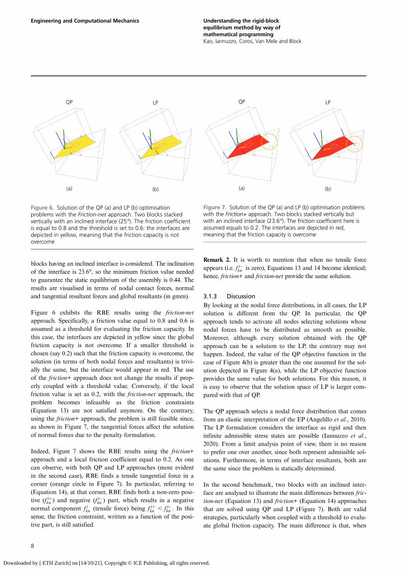
Figure 6 exhibits the RBE results using the friction-netapproach. Specifically, a friction value equal to 0.8 and 0.6 isassumed as a threshold for evaluating the friction capacity. Inthis case, the interfaces are depicted in yellow since the globalfriction capacity is not overcome. If a smaller threshold ischosen (say 0.2) such that the friction capacity is overcome, thesolution (in terms of both nodal forces and resultants) is trivi-ally the same, but the interface would appear in red. The useof the friction+ approach does not change the results if prop-erly coupled with a threshold value. Conversely, if the localfriction value is set as 0.2, with the friction-net approach, theproblem becomes infeasible as the friction constraints(Equation 13) are not satisfied anymore. On the contrary,using the friction+ approach, the problem is still feasible since,as shown in Figure 7, the tangential forces affect the solutionof normal forces due to the penalty formulation.
Indeed, Figure 7 shows the RBE results using the friction+approach and a local friction coefficient equal to 0.2. As onecan observe, with both QP and LP approaches (more evidentin the second case), RBE finds a tensile tangential force in acorner (orange circle in Figure 7). In particular, referring to(Equation 14), at that corner, RBE finds both a non-zero posi-tive (f iþkn ) and negative (f i�kn ) part, which results in a negativenormal component f ikn (tensile force) being f iþkn , f i�kn . In thissense, the friction constraint, written as a function of the posi-tive part, is still satisfied.
Remark 2. It is worth to mention that when no tensile forceappears (i.e. f i�kn is zero), Equations 13 and 14 become identical;hence, friction+ and friction-net provide the same solution.
3.1.3 DiscussionBy looking at the nodal force distributions, in all cases, the LPsolution is different from the QP. In particular, the QPapproach tends to activate all nodes selecting solutions whosenodal forces have to be distributed as smooth as possible.Moreover, although every solution obtained with the QPapproach can be a solution to the LP, the contrary may nothappen. Indeed, the value of the QP objective function in thecase of Figure 4(b) is greater than the one assumed for the sol-ution depicted in Figure 4(a), while the LP objective functionprovides the same value for both solutions. For this reason, itis easy to observe that the solution space of LP is larger com-pared with that of QP.
The QP approach selects a nodal force distribution that comesfrom an elastic interpretation of the EP (Angelillo et al., 2010).The LP formulation considers the interface as rigid and theninfinite admissible stress states are possible (Iannuzzo et al.,2020). From a limit analysis point of view, there is no reasonto prefer one over another, since both represent admissible sol-utions. Furthermore, in terms of interface resultants, both arethe same since the problem is statically determined.
In the second benchmark, two blocks with an inclined inter-face are analysed to illustrate the main differences between fric-tion-net (Equation 13) and friction+ (Equation 14) approachesthat are solved using QP and LP (Figure 7). Both are validstrategies, particularly when coupled with a threshold to evalu-ate global friction capacity. The main difference is that, when
QP LP
(a) (b)
Figure 6. Solution of the QP (a) and LP (b) optimisationproblems with the Friction-net approach. Two blocks stackedvertically with an inclined interface (25°). The friction coefficientis equal to 0:8 and the threshold is set to 0:6: the interfaces aredepicted in yellow, meaning that the friction capacity is notovercome
QP LP
(a) (b)
Figure 7. Solution of the QP (a) and LP (b) optimisation problemswith the Friction+ approach. Two blocks stacked vertically butwith an inclined interface (23:6°). The friction coefficient here isassumed equals to 0:2. The interfaces are depicted in red,meaning that the friction capacity is overcome
8
Engineering and Computational Mechanics Understanding the rigid-blockequilibrium method by way ofmathematical programmingKao, Iannuzzo, Coros, Van Mele and Block
Downloaded by [ ETH Zurich] on [14/10/21]. Copyright © ICE Publishing, all rights reserved.

the local friction value is overcome, the problem is infeasiblewith the friction-net approach, whereas with the friction+approach it is still feasible but the normal force distribution isaffected by the tangential behaviour due to the penalty formu-lation. In this sense, the friction+ approach seems more in-linewith the aim of RBE. Physically, it can be imagined that thefriction+ approach activates a tensile capacity (as a glue) thatalso provides a shear strength. Nonetheless, for many masonryproblems, the friction-net approach is more useful when theaim is to explore the feasibility of the problem to catch ulti-mate equilibrium states. For this reason, in what follows, thefriction-net strategy is adopted, assuming the friction coeffi-cient to be 0.8 and the friction threshold to be 0.6.
3.2 Semi-circular arch on buttressesIn this section, a semi-circular arch on buttresses is considered toillustrate how RBE can be applied to assess unreinforcedmasonry structures. The geometry of the buttressed arch is thesame used in Iannuzzo et al. (2020) where it was analysed toshow the peculiarities of the piecewise rigid displacement (PRD)method, an energy-based limit analysis approach (Iannuzzo,2019; Iannuzzo et al., 2018). The semi-circular arch has aninternal radius of 1.00 m, a thickness of 0.30 m, an orthogonaldepth of 0.50 m and is discretised into 15 voussoirs. The twobuttresses have a height of 2.5 m, a base of 0.70 m and a depthof 1.00 m and are partitioned into 12 elements. The two bottomblocks of the buttresses are considered as supports. The structurehas a uniformly distributed mass density ρ ¼ 1800kg=m3, and0.6 is assumed as the friction threshold. In Section 3.2.1, theinitial geometry is analysed. In Section 3.2.2, how to exploredifferent equilibrated solutions is shown, whereas in Section3.2.3, a tilting test of the structure is performed.
3.2.1 Initial configuration: LP against QP solutionsThe first analysis considers the buttressed arch in its initial con-figuration. Figure 8 shows the solutions obtained by solvingthe QP and LP, respectively. As in the previous examples, thenodal force distributions, highlighted by the blue colour gradi-ent, are different. However, although the two stacked blocks ofSection 3 can admit only one equilibrated solution in terms ofinterface resultants, as the buttressed arch is statically indeter-minate, the interface resultants are not the same, even if almostidentical. Indeed, both QP and LP return solutions close tothe minimum thrust. Moreover, as one can observe, thrusts inthe buttresses are everywhere within the kern, meaning that allbuttress interfaces are activated fully in compression.
3.2.2 Explore different admissible-equilibratedstress states
In this section, a procedure is illustrated that can be used toexplore different admissible, singular, internal, stress states.The idea is to consider new virtual interfaces, which can be
obtained by tightening the original interface and writing theequilibrium Equation 8 on these new (reduced) interfaces.Following this approach, a thrust line solving the EP is con-sidered, that either crosses or is as close as possible to the new,reduced interfaces. A similar procedure was adopted byIannuzzo et al. (2020) using the PRD method. Although, inIannuzzo et al. (2020) only a precise Yes/No answer could beobtained, with the RBE approach and its penalty formulationa solution can also be selected that does not fit the prescribedrequirement completely. In this case, tensile forces on thenodes of the reduced interfaces can appear, meaning that thethrust line cannot be contained within the reduced interfaces.
In Figures 9(a) and 9(c), the key-stone interface is tightened toexplore a maximum thrust condition for the semi-circular arch,which leads the buttresses under the worst working conditions,being the interface resultants outside the kern at the bases ofthe buttresses. Figures 9(b) and 9(d) show the results obtainedby enforcing the thrust line to go through the kern of all inter-faces of the arch (kern-fitting). Both the QP and LP returnalmost identical interface resultants, thus only the resultantforces are visualised.
Moreover, using the friction-net approach, it can be possible toselect an internal stress state that also fulfils particular require-ments of the friction capacity. Indeed, if a low value for thefriction coefficient is chosen (thus, without adopting athreshold strategy), the problem can become infeasible. Thelowest value of the friction angle for which the problem is stillfeasible represents the minimum friction value required by theassembly to be in static equilibrium. In this case, the minimumvalue is found to be 0.31. In Figure 10(a), the solutions for thecorresponding EPs are depicted both in terms of nodal forces
QP LP
(a) (b)
Figure 8. A buttressed arch in its initial reference configuration:both QP (a) and LP (b) solutions return a thrust line that is linkedto a minimum thrust condition of the semi-circular arch. Theinterface resultants in the buttresses are everywhere within thecorresponding interface kern
9
Engineering and Computational Mechanics Understanding the rigid-blockequilibrium method by way ofmathematical programmingKao, Iannuzzo, Coros, Van Mele and Block
Downloaded by [ ETH Zurich] on [14/10/21]. Copyright © ICE Publishing, all rights reserved.

and resultants. It can be noted that the resultants are every-where within the reduced friction cone.
3.2.3 Tilting test: horizontal external forcesA common way adopted for considering the stability of masonrystructures when subjected to horizontal static forces is toperform a tilting test (Block et al., 2006b). This scenario is mod-elled by rotating the gravity vector until tensile forces appear.The maximum value of the tilting angle for which the thrust lineis everywhere within the structural domain is 12°, which corre-sponds to a horizontal static multiplier of 0.21, which is veryclose to the one found in Iannuzzo et al. (2020). In Figure 10(b),the solutions are depicted: it touches the structural boundary infour points, three on the arch and one at the base on the right.These four points suggest a mechanism that is the same as thatfound in Iannuzzo et al. (2020), as the PRD approach allowsalso evaluating mechanisms due to seismic forces.
3.2.4 DiscussionIn this section, considering a buttressed arch, some RBE ana-lyses are performed using both QP and LP approaches: assessing
the initial configuration; exploring various internal equilibria;finding the minimum friction and evaluating the maximum hori-zontal static multiplier for which the assembly is still in equili-brium. All analyses show that solving the QP and LP, differentnodal forces can be obtained, confirming the discussion inSection 3.1. Despite the case of stacked blocks, which is globally(in terms of interface resultants) statically determined, the but-tressed arch is globally statically indeterminate, and, for thisreason, when the initial configuration is considered, the QP andLP solutions, in terms of resultants, are slightly different.Nonetheless, the QP and LP solutions are the same whenapproaching a limit state (e.g. tilting test), since the solution isunique and using the friction-net approach is dictated by thefeasibility of the problem. In the next section, how an increase inthe global indeterminacy of the system can increase the differ-ences between QP and LP is shown. Nonetheless, it is pointedout that in any case, solutions coming from both the optimis-ations represent two statically admissible stress fields, and in thissense, safe solutions matching the spirit of the safe theorem.
3.3 Hemispherical domeIn this section, a hemispherical dome is considered with anoculus to illustrate how to apply RBE to assess 3D-unrein-forced masonry structures. The centre-line radius R of thedome is 5 m whereas the thickness t is assumed to linearlyvary from the bottom base (0.50 m) to the top part (0.25 m).The radius r of the oculus is 1 m.
The dome is discretised using 14 meridian slices and 10 in par-allels; therefore, the number of blocks is 140. The blocks of thebottom ring are assumed as supports (Figure 11). The struc-tural complexity of the dome is larger than the one of the
Maximum thrust QP/LP Arch kern-fitting QP/LP
(b)(a)
(d)(c)
Figure 9. In (a), the mid-span interface of the semi-circular arch isreduced as highlighted in (c) to select an admissible internal stressstate for which the thrusts exerted on the buttresses aremaximised. The same solution can be obtained by reducing thetwo base-interfaces of the arch (towards the extrados). In (b), theinterfaces of the semi-circular arch are virtually reduced to theirkerns as highlighted in (d) to seek if there is a thrust line that fullyactivates the arch in compression. As one can observe, the thrustis outside the mid-span interface. For both examples, the resultsof the QP and LP are almost identical, so the resultant can only bevisualised in (a) and (b)
QP LP
(a) (b)
Figure 10. In (a), using the friction-net approach, RBE returns0.31 as the lowest value of the friction coefficient for which theassembly is still in equilibrium. The resultants are everywhere inthe friction cone. In (b), the buttressed arch subjected to a tiltingtest: the maximum angle for which the resultants are everywherewithin the structural geometry is 12°
10
Engineering and Computational Mechanics Understanding the rigid-blockequilibrium method by way ofmathematical programmingKao, Iannuzzo, Coros, Van Mele and Block
Downloaded by [ ETH Zurich] on [14/10/21]. Copyright © ICE Publishing, all rights reserved.

buttressed arch since, in the present case, the graph G V ;Eð Þdescribing the data structure is 2D. In Section 3.3.1, the initialgeometry is analysed using both QP and LP. In Section 3.3.2,different equilibrium solutions are explored, including kern-fitting and inner/outer base-fitting analysis. In Section 3.3.3,the dome subjected to horizontal action is assessed and themaximum value of the horizontal multiplier is defined.
3.3.1 Initial configuration: LP against QP solutionsIn this section, an RBE analysis of the reference configurationis proposed, without considering any further constraint.Figures 12(a) and 12(b) show results from QP and LP optimis-ations. The interfaces are still coloured using a blue-gradientcolour map. However, the white interfaces denote the sectionswithout any nodal force, or with forces less than a thresholdvalue fixed at 10�2 of the maximum compressive force. Eventhough RBE can provide stress solutions with tensile forces, itreturns a purely compressive internal stress state for which partof the meridian interfaces are affected by zero hoop forces(Heyman, 1997). Nonetheless, QP and LP solutions showdifferent nodal force distributions that illustrate how the differ-ence in terms of interface resultants is more evident in thepresent case than that in the previous ones. This aspect reflectson the extension (from the base) of the non-zero hoop-forcesarea (Figure 12). Moreover, the QP resultant is radialsymmetric whereas the one from LP is not.
3.3.2 Exploring different equilibrium statesIn this section, different internal stress states are explored. Thefirst analysis is what is called a kern-fitting analysis – that is,an internal admissible stress field is considered, that every-where is within the kern of all interfaces. The kern-fitting
analysis coupled with the next inner/outer base-fitting analysiscan provide a measure of the stability of the dome under itsself-weight, and whose results can be related to the geometricsafety factor (Huerta, 2006b). In Figures 13(a) and 13(b), theresults of a kern-fitting RBE analysis are depicted: the inter-faces are virtually reduced to their kern to seek if there is aninternal stress field that fully activates all contacts. Figures 13(c)–13(f) show the results of two analyses aimed at exploringadmissible stress fields that are as much as possible close to theouter and inner parts of the supports, respectively. Theseresults are obtained by virtually shrinking the bottom inter-faces towards either the outer or the inner surface.
3.3.3 Tilting test: horizontal external forcesAs for the buttressed arch, a tilting test is performed to explorethe maximum allowable capacity of the dome subjected tohorizontal actions. The maximum tilting angle found withRBE and both LP and QP analyses is 32°. Figure 14 shows theflow of the resultants within the structure. Despite the previouscase, this RBE analysis is stopped because, using the friction-net approach, the problem becomes infeasible before tensilestresses appear (0:6 is adopted as the local friction value, to beconsistent with the threshold value used in all analyses).
3.3.4 DiscussionIn this section, looking at a dome with an oculus, different equili-brium solutions on the reference configuration are exploredchecking also its maximum capacity under increasing horizontalstatic actions. First, looking at the RBE analyses proposed inSections 3.3.1 and 3.3.2, it is worth noting that even though RBEis based on a penalty formulation, which allows tensile forces, italways returns (when admissible) solutions having part of themeridian interfaces affected by zero hoop forces. Second, the
r
t R
Figure 11. Cross-section and discretisation of the hemisphericaldome: main dimensions. The mean radius R is 5 m; the radius ofthe oculus r is 1 m and the thickness t is assumed to linearly varyfrom 0.5 m (base) to 0.25 m (oculus)
QP LP
(a) (b)
Figure 12. RBE analysis of the reference configuration: QP (a) andLP (b) solutions. The interface colour-distribution shows that thesetwo solutions are locally different. Moreover, also the interfaceresultants are different, being the QP solution radial-symmetric.The white interfaces denote zero hoop-force regions
11
Engineering and Computational Mechanics Understanding the rigid-blockequilibrium method by way ofmathematical programmingKao, Iannuzzo, Coros, Van Mele and Block
Downloaded by [ ETH Zurich] on [14/10/21]. Copyright © ICE Publishing, all rights reserved.

structural complexity of a dome is higher than the one of a but-tressed arch, being the network of the graph GðV ;EÞ bi-dimen-sional. From this aspect, the hemispherical dome reflects into alarger statically indeterminate problem, which also affects theoutput of the QP and LP analyses, showing larger differences ifcompared with the buttressed arch. It has been shown how RBEcan be used to explore different singular, internal stress states byusing virtual interfaces (Section 3.3.3). Despite other force-basedapproaches (e.g. thrust network analysis by Block, 2009), theRBE objective function does not allow handling the value of theforces in particular points directly. This aspect can be addressed
by changing the objective function to one that takes only intoaccount the value of the force in certain points (e.g. on the sup-ports) and/or directions (e.g. horizontal, vertical, tangential, etc.).The capacity of the dome subjected to increasing, horizontalstatic actions has been explored. In this case, the incrementalanalysis ends because the problem becomes infeasible, and in thiscase the objective function does not play any role anymore.
4. DiscussionIn this section, the main outcome is summarised into twomain discussion points.
First, two different objective functions have been proposed andcompared, a LP and the original QP, to illustrate the RBE fea-tures. The main outcome is that both QP and LP provide stati-cally admissible solutions in the spirit of limit analysis,meaning that there should not be any reason to prefer one tothe other. To illustrate this concept, one can observe Figure 4.The two blocks are in contact in four points: it can be possibleto interpret the QP and LP results making parallelism with thefour-legged stool simply supported on the ground (an exampleoften used to explain the limit analysis approach; Heyman,1997, 2019). The four-legged stool is a statically indeterminatesystem and, thus, infinite solutions are possible depending onthe actual contact (unknowable) between the table and theground. The QP solution reported in Figure 4(a) represents anideal elastic solution, meaning that the contact is assumed tohappen in four points. All nodal forces are as much distributedas possible since the objective function is quadratic, which canbe correlated with linear elastic interface energy. Conversely,the LP solution presented in Figure 4(b) is just one of the infi-nite admissible solutions. The equilibrium is guaranteed usingonly two contact points. Furthermore, looking at the results ofSection 3.1, the solution provided by the LP objective functioncannot minimise the QP. On the contrary, QP solutions arealways solutions to the LP. In this sense, the LP objective
QP
Kern-fitting
Inner base-fitting
Outer base-fitting
LP
(a) (b)
(c) (d)
(e) (f)
Figure 13. In (a, b), the results of the kern-fitting RBE analysis: QP(a) and LP (b) solutions. The interface resultants are enforced to gothrough all interface kerns. In (c, d), the resultants are enforced togo through the inner part of the support: QP (c) and LP (d)solutions. In (e, f), the resultants are enforced to go through theouter part of the support: QP (e) and LP (f) solutions. In all cases,QP and LP return two solutions that are very similar, particularly ifone looks at the non-zero hoop-force areas
(a) (b)
Figure 14. Horizontal capacity analysis: the maximum tiltingangle is 32°, obtained with both QP and LP approaches: top view(a) and side-view (b).
12
Engineering and Computational Mechanics Understanding the rigid-blockequilibrium method by way ofmathematical programmingKao, Iannuzzo, Coros, Van Mele and Block
Downloaded by [ ETH Zurich] on [14/10/21]. Copyright © ICE Publishing, all rights reserved.

function further widens the space of solutions provided by theQP optimisation. Despite the force distribution is indetermi-nate, the structure is statically determined if the two blocksassembly globally are considered. The solution in terms ofresultants has to be the same regardless of the objective func-tion. As the structural indeterminacy grows up, the solutionsof the QP and LP approaches start becoming different fromeach other (Sections 3.2 and 3.3). The higher the indetermi-nacy is, the greater the differences are. Indeed, in the domecase, the LP and QP solutions show the highest differences,even in terms of resultants. Finally, if the aim is to select a‘smooth’ solution, the QP provides elastic solutions that are asmuch as possible distributed, which also reflects into sym-metric solutions for symmetric models. If the aim is to widenthe QP solution space, the LP can provide admissible solutionsthat are consistent with a perfectly rigid model.
Second, it has been shown that the RBE method can be used toexplore different equilibrated states of an indeterminate structure.The concept of new virtual interfaces is utilised, which can beobtained by tightening the original interface andwriting the equi-librium constraint on these virtual interfaces. Particularly, intro-ducing the correct definition of the kern of a section, admissiblesolutions are considered, that can fully activate a set of selectedinterfaces. This aspect is crucial when the need is to assess thestability of a structure, especially through the estimation of thegeometric safety factor. Finally, even if RBE is based on apenalty formulation, it has been demonstrated that this does notaffect the search for a limit state. Specifically, when the structureis under a limit condition, the space of solutions may includeonly one element if the solution is unique (see Sections 3.2.3 and3.3.3, where tilting test analyses were performed).
5. ConclusionIn this paper, the RBE method has been explored and furtherdeveloped, paying particular attention to typical masonryassessment problems. RBE is a force-based method that solvesthe EP through an optimisation process where the objectivefunction minimises the total amount of interface forces andthe constraints are represented by linear relations enforcing thestatic equilibrium and the friction failure conditions. It isworth pointing out that tensile forces are allowed even thoughhighly penalised: in this sense, RBE enlarges the space ofadmissible stress states. Currently, RBE is implemented inCOMPAS (Van Mele et al., 2017) and it is an open-source,Python-based package within the COMPAS Masonry frame-work (Iannuzzo et al., 2021). First, the RBE analysis of twosimple benchmark cases has been performed to show themeaning of the nodal contact forces and to illustrate how thefriction capacity is handled. Second, the same buttressed archproposed in Iannuzzo et al. (2020) has been analysed to bench-mark and illustrate the potential of RBE clearly. Finally, a
dome with an oculus has been considered, to show how RBEcan be used to assess 3D structures also. The main insights ofthe current research study are the following:
& the kern of a generic polygonal interface has beenintroduced as a primal variable in the optimisation process.Its use allows to assess and define the range of externalactions for which the structure or its part is fully workingin compression;
& how to use RBE to explore different internal admissiblestress states by virtually reducing the interface (e.g. to itskern) is highlighted. This is a key aspect of RBE method,since it leaves the problem feasible as the virtual reductiondoes not affect the feasibility of the problem, and in thissense, RBE returns as a solution the one that best matchesthe prescribed requirement;
& furthermore, since RBE implicitly takes the thickness ofthe assembly into account, it provides a larger range ofstatically admissible solutions when compared withmethods that use compressive 2D or one-dimensionalelements;
& the main differences in using a friction-net and friction+approach are highlighted and it is shown how the friction-net approach can be more useful when the aim is toevaluate ultimate states ruled by the friction capacity (e.g.3D mechanisms, Section 3.3.3); and,
& to understand the rule of the nodal forces, all analyses areperformed and compared using the original quadraticobjective function and a linear one. They both provideadmissible stress states but the difference among themincreases as the dimension of the graph network, as thusalso indeterminacy of problem increases. The quadraticformulation considers the distribution of the nodal forcesas much as possible and it comes from an elasticinterpretation of the contact among blocks, whereas thelinear one considers interface as a rigid element.
The main outcome of this paper is that both QP and LPapproaches provide statically admissible solutions in the senseof limit analysis. Since in reality, it is hopeless to try to under-stand the actual contact condition, there is no reason to preferone to another, being each solution a possible admissible stressstate. Unless one has to face very large problems, for which LPsolutions are more affordable (i.e. less time consuming). In thislight, RBE is a powerful tool that can be used to explore awide range of equilibrium states and corresponding stresssolutions and its use allows tackling typical masonry assess-ment problems properly.
AcknowledgementsThis study was supported by the NCCR DFAB (NationalCentre of Competence in Research in Digital Fabrication in
13
Engineering and Computational Mechanics Understanding the rigid-blockequilibrium method by way ofmathematical programmingKao, Iannuzzo, Coros, Van Mele and Block
Downloaded by [ ETH Zurich] on [14/10/21]. Copyright © ICE Publishing, all rights reserved.

Architecture) funded by the Swiss National ScienceFoundation (project number 51NF40-141853) and by theSNSF – Swiss National Science Foundation (Project number178953: ‘Practical Stability Assessment Strategies for VaultedUnreinforced Masonry Structures’).
REFERENCES
Angelillo M and Fortunato A (2004) Equilibrium of masonry vaults. InNovel Approaches in Civil Engineering. Lecture Notes in Appliedand Computational Mechanics (Frémond M and Maceri F (eds)).Springer, Berlin, Heidelberg, Germany, vol. 14, pp. 105–111,https://doi.org/10.1007/978-3-540-45287-4_6.
Angelillo M, Cardamone L and Fortunato A (2010) A numerical modelfor masonry-like structures. Journal of Mechanics of Materialsand Structures 5(4): 583–615, https://doi.org/10.2140/jomms.2010.5.583.
Angelillo M, Fortunato A, Gesualdo A et al. (2018) Rigid block modelsfor masonry structures. International Journal of Masonry Researchand Innovation 3(4): 349–368, https://doi.org/10.1504/IJMRI.2018.095701.
Block P (2009) Thrust Network Analysis: Exploring Three-DimensionalEquilibrium. Doctoral dissertation, Massachusetts Institute ofTechnology, Boston, MA, USA.
Block P and Lachauer L (2014) Three-dimensional funicular analysis ofmasonry vaults. Mechanics Research Communications 56: 53–60,https://doi.org/10.1016/j.mechrescom.2013.11.010.
Block P and Ochsendorf JA (2007) Thrust network analysis: a newmethodology for three-dimensional equilibrium. Journal of theInternational Association for Shell and Spatial Structure 48(3):167–173.
Block P, Ciblac T and Ochsendorf JA (2006a) Real-time limit analysis ofvaulted masonry buildings. Computers & Structures 84(29-30):1841–1852, https://doi.org/10.1016/j.compstruc.2006.08.002.
Block P, DeJong MJ and Ochsendorf JA (2006b) As hangs the flexibleline: equilibrium of masonry arches. Nexus Network Journal 8(2):13–24, https://doi.org/10.1007/s00004-006-0015-9.
Bullet-Physics-Library (2012) (Copyright © 2012) Bullet collisiondetection and physics library. http://bulletphysics.org.
Como M (2013) Statics of Historic Masonry Constructions. Springer,Berlin, Heidelberg, Germany.
CPLEX II (2009) V12. 1: User’s Manual for CPLEX. International BusinessMachines Corporation, Armonk, NY, USA, vol. 46, (53), p. 157.
Cundall PA (1971) A computer model for simulating progressivelarge scale movements in blocky rock systems. In Proceedingsof the International Symposium on Rock Mechanics, Nancy, France.
D’Ayala D and Casapulla C (2001) Limit state analysis of hemisphericaldomes with finite friction. In Historical Constructions, Possibilitiesof Numerical and Experimental Techniques, Guimarães (LourençoP.B. and Roca P. (eds)), pp. 617–626.
De Chiara E, Cennamo C, Gesualdo A et al. (2019) Automatic generationof statically admissible stress fields in masonry vaults. Journal ofMechanics of Materials and Structures 14(5): 719–737, https://doi.org/10.2140/jomms.2019.14.719.
Diamond S and Boyd S (2016) CVXPY: a Python-embedded modelinglanguage for convex optimization. The Journal of MachineLearning Research 17(1): 2909–2913, https://doi.org/10.5555/2946645.3007036.
Fraternali F (2010) A thrust network approach to the equilibriumproblem of unreinforced masonry vaults via polyhedral stressfunctions. Mechanics Research Communications 37(2): 198–204,https://doi.org/10.1016/j.mechrescom.2009.12.010.
Fraternali F, Angelillo M and Fortunato A (2002) A lumped stressmethod for plane elastic problems and the discrete-continuumapproximation. International Journal of Solids and Structures39(25): 6211–6240, https://doi.org/10.1016/S0020-7683(02)00472-9.
Frick U, Van Mele T and Block P (2015) Decomposing three-dimensionalshapes into self-supporting, discrete-element assemblies.Modelling Behaviour 187–201, https://doi.org/10.1007/978-3-319-24208-8_16.
Frick U, Van Mele T and Block P (2016) Data management andmodelling of complex interfaces in imperfect discrete-elementassemblies. In Proceedings of the IASS Annual Symposia.International Association for Shell and Spatial Structures (IASS),vol. 17, pp. 1–9.
Gesualdo A, Brandonisio G, De Luca A et al. (2019) Limit analysis ofcloister vaults: the case study of Palazzo Caracciolo di Avellino.Journal of Mechanics of Materials and Structures 14(5): 739–750,https://doi.org/10.2140/jomms.2019.14.739.
Gilbert M and Melbourne C (1994) Rigid-block analysis of masonrystructures. Structural Engineer 72(21): 356–361.
Gilbert M, Casapulla C and Ahmed HM (2006) Limit analysisof masonry block structures with non-associative frictional jointsusing linear programming. Computers & Structures 84(13–14):873–887, https://doi.org/10.1016/j.compstruc.2006.02.005.
Hally D (1987) Calculation of the Moments of Polygons. DefenceResearch Establishment Suffield, Ralston, AB, USA.
Heyman J (1966) The stone skeleton. International Journal ofSolids and Structures 2(2): 249–279, https://doi.org/10.1016/0020-7683(66)90018-7.
Heyman J (1969) The safety of masonry arches. International Journal ofMechanical Sciences 11(4): 363–385, https://doi.org/10.1016/0020-7403(69)90070-8.
Heyman J (1997) The Stone Skeleton: Structural Engineering of MasonryArchitecture. Cambridge University Press, Cambridge, UK.
Heyman J (2019) The structural engineer’s view of ancient buildings.Journal of Mechanics of Materials and Structures 13(5): 609–615,https://doi.org/10.2140/jomms.2018.13.609.
Huerta S (2006a) Galileo was wrong: the geometrical design ofmasonry arches. Nexus Network Journal 8(2): 25–52,https://doi.org/10.1007/s00004-006-0016-8.
Huerta S (2006b) Geometry and equilibrium: the gothic theory ofstructural design. The Structural Engineer 84(2): 23–28.
Iannuzzo A (2019) Energy based fracture identification in masonrystructures: the case study of the church of ‘Pietà dei Turchini’.Journal of Mechanics of Materials and Structures 14(5): 683–702,https://doi.org/10.2140/jomms.2019.14.683.
Iannuzzo A, De Luca A, Fortunato A, Gesualdo A and Angelillo M (2018)Fractures detection in masonry constructions under horizontalseismic forces. Ingegneria Sismica 35(3): 87–103.
Iannuzzo A, Van Mele T and Block P (2020) Piecewise rigid displacement(PRD) method: a limit analysis-based approach to detectmechanisms and internal forces through two dual energy criteria.Mechanics Research Communications 107: 103557, https://doi.org/10.1016/j.mechrescom.2020.103557.
Iannuzzo A, Dell’Endice A, Maia Avelino R et al. (2021) COMPASmasonry: a computational framework for practical assessment ofunreinforced masonry structures. In Proceedings of the SAHCSymposium, Barcelona.
Livesley RK (1978) Limit analysis of structures formed from rigidblocks. International Journal for Numerical Methods in Engineering12(12): 1853–1871, https://doi.org/10.1002/nme.1620121207.
Livesley RK (1992) A computational model for the limit analysis ofthree-dimensional masonry structures. Meccanica 27(3): 161–172,https://doi.org/10.1007/BF00430042.
14
Engineering and Computational Mechanics Understanding the rigid-blockequilibrium method by way ofmathematical programmingKao, Iannuzzo, Coros, Van Mele and Block
Downloaded by [ ETH Zurich] on [14/10/21]. Copyright © ICE Publishing, all rights reserved.

Mousavian E and Casapulla C (2020) The role of different slidingresistances in limit analysis of hemispherical masonry domes.Frattura ed Integrità Strutturale 14(51): 336–355, https://doi.org/10.3221/IGF-ESIS.51.25.
Nvidia Physx Library (2013) See http://www.nvidia.com/object/physx-9.12.0213-driver.html.
Ochsendorf JA (2002) Collapse of Masonry Structures.Doctoral dissertation, University of Cambridge,Cambridge, UK.
Orduña A and Lourenço PB (2005) Three-dimensional limit analysis ofrigid blocks assemblages. Part I: torsion failure on frictionalinterfaces and limit analysis formulation. International Journal ofSolids and Structures 42(18-19): 5140–5160, https://doi.org/10.1016/j.ijsolstr.2005.02.010.
Portioli F, Casapulla C, Gilbert M and Cascini L (2014) Limitanalysis of 3D masonry block structures with non-associativefrictional joints using cone programming. Computers &
Structures 143: 108–121, https://doi.org/10.1016/j.compstruc.2014.07.010.
Portioli F, Casapulla C and Cascini L (2015) An efficient solutionprocedure for crushing failure in 3D limit analysis of masonryblock structures with non-associative frictional joints. InternationalJournal of Solids and Structures 69: 252–266, https://doi.org/10.1016/j.ijsolstr.2015.05.025.
Romano G (2002) Scienza Delle Costruzioni. Hevelius, Benevento, Italy.Van Mele T, Casas G, Rust R et al. (2017) COMPAS: a framework for
computational research in architecture and structures. https://doi.org/10.5281/zenodo.2594510, http://compas-dev.github.io/.
Whiting EJW (2012) Design of Structurally-Sound MasonryBuildings Using 3D Static Analysis. Doctoral dissertation,Massachusetts Institute of Technology, Boston, MA, USA.
Whiting E, Ochsendorf JA and Durand F (2009) Procedural modeling ofstructurally-sound masonry buildings. In ACM SIGGRAPH Asia2009 Papers, pp. 1–9.
How can you contribute?
To discuss this paper, please email up to 500 words to theeditor at [email protected]. Your contribution will beforwarded to the author(s) for a reply and, if consideredappropriate by the editorial board, it will be published asdiscussion in a future issue of the journal.
Proceedings journals rely entirely on contributions from thecivil engineering profession (and allied disciplines).Information about how to submit your paper onlineis available at www.icevirtuallibrary.com/page/authors,where you will also find detailed author guidelines.
15
Engineering and Computational Mechanics Understanding the rigid-blockequilibrium method by way ofmathematical programmingKao, Iannuzzo, Coros, Van Mele and Block
Downloaded by [ ETH Zurich] on [14/10/21]. Copyright © ICE Publishing, all rights reserved.