engineered fiber links for high speed data center ... · pdf file• variation of different...
TRANSCRIPT

"Engineered Fiber Links" for High Speed Data Center Applications – Design, Testing and Trends
Rodney CasteelRCDD, DCDC,NTS, OSPCommScope,Chair TIA FOTC
Robert ReidPanduit
Tyler VanderPloeg, RCDDViavi Solutions
Nicholas GagnonEXFO

• Who Is FOTC – Rodney Casteel• Common Data Center Architectures – Rodney Casteel• High Speed Fiber Plant for Data Centers – Robert Reid• Multi-Fiber Connector Inspection and Cleaning– Tyler, Nicholas• Testing MPO/MTP Trunk Cables – Tyler, Nicholas• Final Questions
Agenda

Fiber Optics Technology ConsortiumOverview:
•Part of the Telecommunications Industry Association (www.tiaonline.org)•Until 2013, we had been known as the Fiber Optics LAN Section (FOLS). Our new name was chosen to reflect our expanding charter.•Formed 21 years ago•Mission: to educate users about the benefits of deploying fiber in customer-owned networks•FOTC provides vendor-neutral information

Fiber Optics Technology Consortium• Current Members
• AFL• Berk-Tek, a Nexans Company• CommScope• Corning• EXFO• Fluke Networks• General Cable
• Current Members
• Viavi• OFS• Panduit• Sumitomo Electric Lightwave• Superior Essex• Legrand Ortronics• The Siemon Company

Fiber Optics Technology Consortium• Maintain a website with Fiber FAQs, White Papers and other resources –
www.tiafotc.org.• Developed and maintain a free Cost Model that allows users to compare
installed first costs of several architectures.• Host a webinar series throughout the year with all webinars available on
demand.• Speak at industry conferences like BICSI• Contribute to industry publications – Like BICSI News.• Conduct market research – like the surveys today

Fiber Optics Technology Consortium• Recent Webinars Available on Demand
– Driving Value in the Data Center with Emerging Multimode Fiber Technologies (Finisar, Dell, CommScope)
– LAN Standards, News & Trends (Legrand, Fluke Networks)
• Visit www.tiafotc.org or our channel on BrightTalk
• Webinars are eligible for CEC credit for up to two years after they are first broadcast. Email [email protected] if you have completed a webinar and want to receive your CEC.

Important NoticeAny product(s) identified or identifiable via a trade name or otherwise in this presentation as a product(s) supplied by a particular supplier(s) is provided for the convenience of users of this presentation and does not constitute an endorsement of any kind by TIA of the product(s) named. This information may be provided as an example of suitable product(s) available commercially. Equivalent product(s) may be used if they can be shown to lead to the same results.

COMMON DATA CENTER ARCHITECTURESRODNEY CASTEEL - COMMSCOPE

Data Centers undergoing change
Bandwidth Explosion
Internet of Things
Cloud Computing

Sources: Cisco and Deloitte
Cloud Data
3xMobile Data
10xIP Video
4xInternet
3xBroadband
2x
Global Bandwidth Trends (2014-2019)

Data Center ModelTraditional 3-Tier Architecture Model
chitecture Model

Data Center Model: Leaf/Spine design
Server Connections
Leaf Switches
Spine Switches
Server Connections
Server Connections
Server Connections
Server Connections
Server Connections

Data Center ModelTwo options for cabling infrastructure architecture:1. Serial Duplex
– With SM limited by equipment– With standard OM 3/4 multimode limited by existing serial transceivers– With WBMMF more options for long term higher speed migration
2. Parallel– Can be used with SM and MM fiber– Can be used with WBMMF– Requires more fibers

Cabling Infrastructure - Serial Duplex

12f24f
12f
12f 24f
12f
12f each
12f each 12f each 12f each
Cabling Infrastructure - ParallelExisting (2) 40G connections using MPO cablingExisting (2) 40G connections using MPO cabling
Migration to 100G connection while retaining existing MPO trunk cabling and adapter panels Migration to 100G connection while retaining existing MPO trunk cabling and adapter panels

Cabling Infrastructure Breakout – 10G to 40G
12f each 4 duplex cords412f
12f each 12f each 412f
412f
12f each12f each 412f
412f 412f
40G breakout to (3) 10G LC using existing 10G cabling 40G breakout to (3) 10G LC using existing 10G cabling
(2) 40G breakout to (8) 10G LC (2) 40G breakout to (8) 10G LC
(3) 40G breakout to (12) 10G LC with 100% fiber utilization in trunk cables (3) 40G breakout to (12) 10G LC with 100% fiber utilization in trunk cables

1224f 12f each
12 duplex cords
Cabling Infrastructure Breakout – 10G to 100G120G MPO to (12) 10G LC with individual 10G circuit routing granularity 120G MPO to (12) 10G LC with individual 10G circuit routing granularity

8f24f8f8f
12f each
12f each
12f each
8f24f8f8f
12f each
Cabling Infrastructure Breakout – 40G to 100G 120G MPO breakout to (3) 40G MPO120G MPO breakout to (3) 40G MPO
120G MPO breakout to (3) 40G MPO with 100% fiber utilization in trunk cables 120G MPO breakout to (3) 40G MPO with 100% fiber utilization in trunk cables

Cabling Infrastructure Breakout - 100G to 400G12f each
12f each
12f each8f32f 8f8f8f
12f each8f32f 8f8f8f
8f32f 8f8f8f
8f32f 8f8f8f
400G-SR16 MPO-16 breakout to (4) 100G-SR4 MPO400G-SR16 MPO-16 breakout to (4) 100G-SR4 MPO
(3) 400G-SR16 breakout to (12) 100G-SR4 with 100% fiber utilization in trunk cables (3) 400G-SR16 breakout to (12) 100G-SR4 with 100% fiber utilization in trunk cables

HIGH SPEED FIBER PLANT FOR DATA CENTERSROBERT REID - PANDUIT

AGENDA• Link vs. Channel• Application Power Budgets• The Emergence of “Engineered Links”• Field Test Limits per the Cabling Standards• Tester Capability• Types of Errors• Concept of ‘Guardbanding’• Case Studies• Increasing Field Test Capability

Link vs. ChannelISO/IEC and TIA standards define the Permanent Link as the permanent fiber cabling infrastructure over which the active equipment must communicate. Does not include equipment patch cords to connect the active network devices in equipment distribution areas or the patch cords in cross connect patch areas.
ISO/IEC and TIA standards define Permanent Link testing to verify the performance of the fixed (permanent) segments of installed cabling. Completion of this testing provides assurance that links that pass standards-based (or application-based) limits can reliably be configured into a passing Channel by adding good quality patch cords.

Links

ChannelsServer HDA Channel (BLUE)
Interswitch Backbone Channel (GREEN)

40GBASE-SR4 “Engineered Links”

40GBASE-SR4 “Engineered Link”

40GBASE-SR4 “Engineered Link”

40G Engineered Link Scenario150m MPO trunks reach out to EOR switches and 10m MPO trunks connect the core and cross-connect area. Customer wants to qualify the two trunks as permanent infrastructure to manufacturers ‘ultra’ specifications (and not the TIA limits). So, they would calculate the following “engineered limits”:
Long Side test limit = 2 x 0.25dB + 0.15 km x 3.5dB/km = 1.03dBShort Side test limit = 2 x 0.25dB + 0.01 km x 3.5dB/km = 0.54dB!!!!!
Links tested against the TIA/IEC guidelines would yield the following:
Long Side test limit = 2 x 0.75dB + 0.15 km x 3.5dB/km = 2.03dBShort Side test limit = 2 x 0.75dB + 0.01 km x 3.5dB/km = 1.54dB

LSPM Tester CapabilityANSI/Automotive industry Measurement Systems Analysis definitions of Gauge Repeatability and Reproducibility (GR&R). In the case of field LSPM testing, the gage is the LSPM plus the reference cords that interface to the link under test.
Repeatability - one person repeatedly measures the same item/same test set
Reproducibility - different operators using the same test/same items
The total variance of the actual link measurement (TV), is sum of three components:
• True variation present in the link - Product Variation (PV)
• Variation of different operators (Reproducibility) - ‘Appraiser’ Variation (AV)
• Variance of LSPM error (Repeatability) - Equipment Variation (EV)
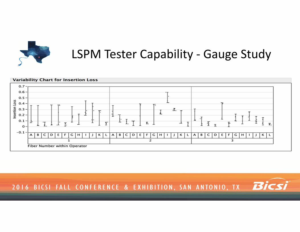
LSPM Tester Capability - Gauge Study

LSPM Tester Capability - Gauge Study

Classifying Errors in Field Test
False FAIL - Indicates fail but truly passing - Impact to customer’s ability to deploy links in a timely fashion. Money is unnecessarily spent in remediating links.False PASS - Indicates pass but truly failing - May present link reliability issues & warranty claim against cabling supplier. “Day Two” issue - links commissioned as good but may impinge on signal integrity required by application.

Concept of ‘Guardbanding’
0.54dB ‘Engineered’ Test LimitCIL (dB)
Acc
epta
nce
Pro
babi
lity
‘Ideal’ Gauge (GR&R = 0.0dB)

Concept of ‘Guardbanding’
CIL (dB)
Acc
epta
nce
Pro
babi
lity
Real Gauge (GR&R = 0.54dB)

Concept of ‘Guardbanding’
CIL (dB)
Acc
epta
nce
Pro
babi
lity
Real Link Loss Distribution

Concept of ‘Guardbanding’
CIL (dB)
Acc
epta
nce
Pro
babi
lity
20% chance of failing a link that has 0.44dB of CIL
20% chance of passing a link that has 0.64dB of CIL
False Fails & Passes
Push green curve by 0.27dB

Concept of ‘Guardbanding’
0% chance of failing a good link that is at the limit of the product variation (0.54dB)
Push green curve by 0.27dB
CIL (dB)
Acc
epta
nce
Pro
babi
lity

LSPM vs Factory Test Certification

Case Study - Product Return

Field Test Case Study - Financial DC

Field Test Case Study - Financial DC

Field Test Case Study - Government DC

Field Test Case Study - Government DC

Increasing Field Test Capability• Telcordia GR 326 - Guidance on longevity/durability and maintenance of ref.
cords - Left to the individuals performing testing to assess the integrity of cords
• Use one jumper method to qualify ref. cord connectors on a ‘schedule’ & when ref. cords are in question (instead of a fixed # of mating cycles)
• Judge efficacy of ref. cord by performing one jumper loss on ends that interface to LUT with a ‘master’ cord that is purpose-built to qualify working reference cords. If possible, chart (or at least log) these measurements to determine the “state of control”

Increasing Field Test Capability• Allocate the actual # of mated pairs of connectors in link into link power
budget, irrespective of link measurement technique chosen• For tight engineered links, assess limits against test set GR&R and if it
infringes the capability to test, negotiate to modify limits upward by one half of the GR&R (0.25dB/0.3dB typically). Good point to engage the cabling supplier to provide guidance and a technical bridge between the end-customer and the SI/Installer
• Adhere to good cleaning/inspection practices - “When in doubt, clean it” (anything that touches the link under test, including the test equipment reference cords, visual inspection equipment, etc.)

Testing
Tyler Vander Ploeg, RCDD Solutions Marketing ManagerViavi Solutions
Nicholas GagnonBusiness Development ManagerEXFO

Agenda• Overview
– MTP/MPO– Migrating to 40G
• End-face inspection and certification (MTP/MPO)• Testing: Construction, Maintenance & Upgrades
– Tier 1 Testing (MTP/MPO)– Tier 2 Testing (MTP/MPO)
• Encircled Flux Metric & Wideband MMF• Conclusion

Is MTP/MPO new?

Polarity and Gender

Single Fiber vs. Multi-Fiber ConnectorsSINGLE FIBER CONNECTOR MULTI-FIBER CONNECTOR
White ceramic ferrule One fiber per connector Common types include SC, LC, FC, and ST
Polymer ferrule Multiple fibers in linear array
(for example, 8, 12, 24, 48, and 72) in single connector providing high-density connectivity
Common type is MPO or MTP®

Focused on the ConnectionAdapter
MPO Unpinned (Female)
MPO Pinned (Male)
MPO Guiding holes
MPO Guiding pins

Focused on the ConnectionPhysical Contact The Physical Contact area is the critical
joining point in the fiber network. If there is no clean physical connection, the light path is disrupted and the connection is compromised.
Multiple connects-disconnects may create fiber misalignments due to guiding pins guiding holes or memory shape related issues (transceivers MACs)

Top-view Cross Section 12 Fiber MTP/MPO - Clean
Physical Contact
Example ofClean Connection(no contamination)
1
2
3
4
5
6
7
8
9
10
11
12

Top-view Cross Section (1–12 Fibers)
Particle Dirt
Example ofDirty Connection(contamination causing air gaps, back reflection, insertion loss)
Air Gap1
2
3
4
5
6
7
8
9
10
11
12
Dirt
Back Reflection
Insertion Loss

If a critical connection is affected, the impact can be exponential
The exponential impact of contamination
Image property of CommScope

Today’s 1G/10G Networks
Duplex Cords(6x2 Fibers)
Duplex Cords(6x2 Fibers)
Cassettes(in enclosure)
Cassettes(in enclosure)
Backbone(12 Fibers)
Harness6x2-Fibers
to12-Fibers
MTP/MPO Adapter
MTP/MPO Adapter
Harness6x2-Fibers
to12-Fibers
Backbone(12 Fibers)
Patch Cords & Cassettes
Harnesses & Adapter Panels
1
2

Today’s 40G to 10G Network Integration
10G Enabled Switch
Duplex Lane Assignment
40G to 10G conversion Polarity? Method A, Method B, Method C Fiber position conversion from 40G Core to 10G Edge MTP/MPO pinned or unpinned; Tab Up or Tab Down Architecture scalable to 100G (switch) to 25G
40G BASE-SR4 Lane Assignments
Harness12-Fibers
to4x2-Fibers
Backbone(12 Fibers)
MPO Adapter or cassette
12 –FiberMPO
4 servers –10G to each server

Migrating to 40G Network40GBASE-SR4
Cassettes are replaced by MTP/MPO adapter panel
Patch Cord is now 12-fiber with MTP/MPO
Backbone now supports one 40GbE channel, using 8 fibers instead of six duplex 10GbE
channels
40G BASE-SR4 Lane Assignments

Data Center Examples of MTP/MPO/Fiber
12 fiber MTP/MPO backbone w/Cassettes at either endFiber consolidation and migration path SFP/SPF+ at each end
6 – 1/10Gbps Ethernet Links (MMF)6 – 1/10/40/100Gbps Ethernet Links (SMF)
8 fiber MTP/MPO backbone w/Cassette at server endFiber consolidation and migration pathQSFP at switch SPF+ at server
4 – 10Gbps Ethernet Links (MMF)
1 - 40Gbps Ethernet Link (MMF – SR4)1 - 40Gbps Ethernet Link (SMF – PSM4)
8 fiber MPO linkQSFP at both ends
MTP/MPO Adapter Panel
MTP/MPO Adapter Panel
MTP/MPO Adapter Panel

60
Fiber Inspection

Industry factors impacting Fiber inspection
Growth of technicians working with fiber• New to Fiber / New to industry• Frequent contractor turnover
New industry practices & architectures• Strict Loss Budgets <.5db loss per connection• No room for mistakes• Plug & Play Cassettes / PON / POLAN
Connectivity Requirements are Standardized• IEC-61300-3-35 (fiber connector end face quality)• TIA 568 (fiber premises cabling)• TIA 942 (datacenters)• Technicians are required to prove compliance
Companies transitioning techs to mobile/tablets and cloud storage• Less expensive / Portable• Can perform multiple job related functions (Phone / email / job tickets, store results, etc.)
Back Reflection = -67.5 dBTotal Loss = 0.250 dB
Back Reflection = -32.5 dBTotal Loss = 4.87 dB
1
CLEAN CONNECTION
DIRTY CONNECTION
3

Inspect Before You ConnectFollow this simple “INSPECT BEFORE YOU CONNECT” process to ensure
fiber end faces are clean prior to mating connectors.

Inspect and Clean Both Connectors in PairInspecting BOTH sides of the connection is the ONLY WAY to ensure that it will
be free of contamination and defects.
Patch cords are easy to access and view compared to the fiber inside the bulkhead, which is frequently overlooked. The bulkhead side may only be half of the connection, but it is far
more likely to be dirty and problematic.
Patch Cord (“Male”) Inspection Bulkhead (“Female”) Inspection

Inspect ALL fibers in a Multi-Fiber Connector

IEC 61300-3-35 Sets Requirements for Connector Quality
CLADDING ZoneCORE Zone
Even for MPO!
Multimode MPO Connectors
Pass/ Fail according to IEC 61300-3-35

Inspecting: NOT a waste of time!Example) BICSI speed challenge 2014• 31 participants from first time testers to technicians with 20 years of
fiber expertise• Average test time : 1:54 to inspect, clean, re-inspect, analyze and
certify
• 5 LC/UPC fiber connectors (2 clean, 2 dirty, 1 scratched)• 1st position: Lester Sebetka, Price Industrial Electric (USA) – time
1:08
New inspection tools are changing the industry:• Make inspection fast• Intuitive• Automated process (focus, test, etc.)• Pair with mobile devices• Store results, generate reports

Industry Standard• A set of requirements for Fiber Optic connector quality• Designed to guarantee insertion loss and return loss
performance• Used as a common reference between supplier & customer or
between work groups• Used as a condition for accurate testing of components or links• Copies of the standard can be purchased from ANSI or your
country’s standards body– www.ANSI.org– Search for “61300-3-35
IEC 61300-3-35

Component Mfg.
System Assembly
System Test
Receiving & QC
Installation
Network Test
Troubleshooting & Maintenance
Where is IEC 61300-3-35 Used?Throughout the Entire FO Product Lifecycle
ANSI/TIA 568.3
ANSI/TIA 568.3
ANSI/TIA 568.3
ANSI/TIA 568.3ANSI/TIA 568.3

Cleaning Best Practices• Many tools exist to clean fiber• Many companies have their own “best practices”• Dry clean first. If that does not clean, then try wet cleaning.• Always finish with dry cleaning!

Fiber Inspection
• Demonstration

Testing: Construction, Maintenance & Upgrades
Tier 1each optical fiber link is measured for its attenuation with an OLTS. Fiber length verification may be obtained from cable sheath markings or via the OLTS. Polarity can be verified with the OLTS while performing attenuation tests. A visible light source, such as a VFL, can also be use to verify polarity.
Tier 2 (Optional) Tier 2 testing supplements Tier 1 testing with the addition of an OTDR trace of the cabling link. The OTDR trace characterizes elements along a fiber link, including fiber segment length, attenuation uniformity and attenuation rate, connector location and insertion loss, splice location and splice loss, and other power loss events such as a sharp bend that may have been incurred during cable installation.
ANSI/TIA-568.3-D (07-2016: Circulating for Default Ballot)Optical Fiber Cabling and Components Standard
ISO-IEC 11801: 2010 (Ed. 2.2)Generic cabling for customer premises

72
MTP/MPO – Tier 1 Testing

Tier 1 Certification Testing Review
• Link Loss (dB), Length & Polarity check using Tier 1 test set• Test loss to pass/fail to maximum link loss budget• Applies to any point-to-point or passive link• Test procedure applies to both multimode and single mode testing• All test access and reference cords must be reference-grade
Optical Patch Panel
EquipmentConnections & splices possible
Equipment Cord
Optical Patch Panel
Fiber Span / LinkEquipment
Cord
Equipment
Rx Tx Tester
Tester TxRx
Reference Cord
Reference Cord
Test Access Cord
Test Access Cord
Fiber Span / Link
Equipment CordsEquipment Cords
Tester TxRx
Rx Tx Tester Reference Cords
2. Reference prior to testingTwo very important things to remember
1.
IBYC
Measured Link Loss (dB) & Length
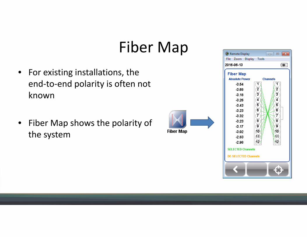
Fiber Map• For existing installations, the
end-to-end polarity is often not known
• Fiber Map shows the polarity of the system

MPO to MPO Loss and Polarity Test
• Test 40G Links and Channels• Ensure polarity and loss
MPO Tester RX
MPO Tester TX
MPO Backbone
MPO BulkheadMPO Bulkhead
MPO Test Cords

MPO to Single Fiber Loss and Polarity Test• One end MPO source – Other end simplex power meter
– Testing from MPO to Fanouts or Cassettes– End-to-end channels for QSFP to 10G– Fiber Map from MPO to LC/SC (simplex)
Tester (LC/SC RX)
Tester (MPO TX)
MPO Backbone
MPO BulkheadMPO Cassette
MPO Test Cord
Simplex Test Cord

MPO Power Meter
• MPO power meter – Using any MPO source– Fault Isolation – Testing output power from 40G optics
Local MPO RXAny Source
MPO Backbone
Bulkhead MPO Bulkhead
MPO Test Cord

Selecting Channels• Can apply to any of the above Test scenarios• Allows selection of which of the 12 channels are
active– At the Remote (TX) and at the Local (RX)
• Helps in cases when 8 or fewer fibers are present in MPO links (e.g. 40GBASE-SR4)
• Results reflect topology• No unwanted “fails” due to nonexistent channels

79
MTP/MPO – Tier 2 Testing

Tier 2 TestingWhen and why is it needed in the Enterprise?Primarily during maintenance as a troubleshooting tool• OTDRs see the link from beginning to end. It’s the only optical test device that can determine if there is
a problem with the physical infrastructure, the severity, and where the problem exists.
Sometimes during construction and link acceptance
• When network won’t turn up initially – troubleshooting cause and location
• Complex networks– Lots of connectors or splices
– Higher speeds more sensitive to loss budget limits and reflections
• Wide Area Networks (longer with many splices and higher speeds)
• Required by customer Service Level Agreement (SLA) as more complete documentation.

Tier 2 Certification• Newer test views simplify testing

10G LC-LC (MTP/MPO trunk) Link MeasurementStep 1: Pre-installation quality test
Step 2: End to end permanent link test

83© 2016 EXFO Inc. All rights reserved.
6xLC
Du
plex
Rece
ive
box
Key UpKey Down
LC12 Receive TailsPermanent Link
MPO12 Launch Leads
21
3 4
5 6
test pointsFIP
test points
MTP/MPO12-LC Link Measurement

Link LengthTotal link lossLink ORLIndividual connection Insertion LossIndividual connection Return LossPass/ Fail diagnostic

85© 2016 EXFO Inc. All rights reserved.
Finger oil
Source: EXFO Application Note 327 – Touching on Failure: Sources of Fiber Optic Issues in the Data Center, December 2015
10-12 dB average change (clean vs. oil)
Strict correlation (clean vs. oil)0.7
0.6
0.5
0.4
0.3
0.2
0.1
0
70
60
50
40
30
20
10
0
* Reference test cords; should have the same or better performance specification as the hardware terminating the cabling under test;
35 dB MMF / 45 dB SMF appears realistic target for 25G+ line rate carrying digital video
Reflectance ISO/IEC 11801 (2010) TIA-568.3-D (2013) ISO-IEC 14763-3 (2014)*
MMF 20 dB 20 dB 35 dB
SMF 35 dB UPC60 dB APC
35dB UPC55 dB analog video
45 dB UPC60 dB APC
Return Loss: the elephant in the room?

MPO OTDR Testing (via MPO Switch)
SC MPO
CH 1
OTDR
USB Cable
MPO Switch
Automatic switching driven by the OTDR via USB

OTDR Testing
• Demonstration

88
Encircled Flux Metric & Wideband Multimode Fiber

Encircled Flux Metric
Various source filling conditions
11
22
33
11 22 33
Use EF-compliant instrument and change the reference-grade test jumpers as recommended
REPEATABILITY, REPRODUCIBILITY and UNCERTAINTY

Encircled Flux Metric vs Mandrel Wrap
OFL/Mandrel Wrap per TIA-426- 14-A, Method B Encircled Flux (EFL) TIA-426-14-B, Annex A Source: Optical loss testing in the field is not as simple as it seems, Belden (2011)
91© 2016 EXFO Inc. All rights reserved.
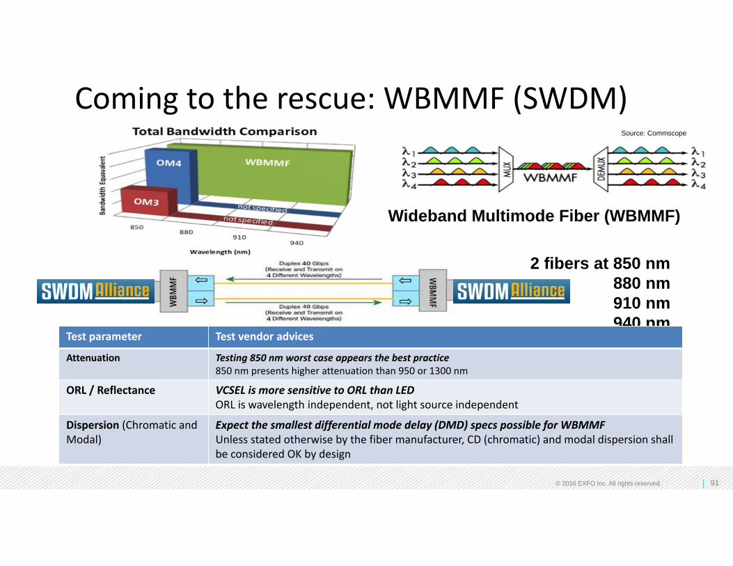
Coming to the rescue: WBMMF (SWDM)
2 fibers at 850 nm880 nm910 nm940 nm
Wideband Multimode Fiber (WBMMF)
Test parameter Test vendor advices
Attenuation Testing 850 nm worst case appears the best practice850 nm presents higher attenuation than 950 or 1300 nm
ORL / Reflectance VCSEL is more sensitive to ORL than LEDORL is wavelength independent, not light source independent
Dispersion (Chromatic and Modal)
Expect the smallest differential mode delay (DMD) specs possible for WBMMFUnless stated otherwise by the fiber manufacturer, CD (chromatic) and modal dispersion shall be considered OK by design
Source: Commscope

LC-LC OLTS Testing
CFP40GbE
transceivers Passive fiber optic infrastructure
MDA switch
Main Distribution
Area
LC Patch panel
MDA Patch Panel
(LC)
LC Patch panel
EDA Patch Panel
(LC)
transceivers
Move, Add and Changes (MACs) of pluggables optics (SM/MM)
WBMMF – SWDM Link Characterization (MM)
4 x 10G blade servers
ToR switch
3 sec. per fiber/ bi-directional, 2 wavelengths

Wrap-up• MPO end-face condition is the most critical element in a channel with MPO connections• Polarity can be a challenge – especially when adapting existing MPO backbones to new services• Be aware of pinned/unpinned – presents challenges for testing (test cords must mate with system –
challenges with test device and test cord gender)• Loss testing is typically done on links
– 1/10G MM, 1/10/40/100G SM link is duplex – 40/100G MM links are SR4/SR10 MPO, PSM4 SM link is MPO, CLR4 SM link is LC duplex
• Testing channels may make sense if hydra (fan cables) are used• OTDR testing of MPO allows for:
– Characterization of the link or channel (uniformity of cable attenuation and connection loss)– Length measurements – Fault isolation to prevent unnecessary service interruptions– Newer Test views make Tier2 testing much easier– Return Loss of connectors: 25Gbps and higher line rates will bring different challenges than 10Gbps
• Wide Band Multimode Fiber (WBMMF) brings more capacity; SWDM transceivers are in developments

Questions?Rodney Casteel RCDD/NTS/OSP/DCDC - CommScope, Chair TIA FOTC
[email protected] Reid – Panduit
[email protected] VanderPloeg RCDD– Viavi Solutions
[email protected] Gagnon – EXFO