engine volkswagen - kamasa tools23161 03a t10050, 23-059, 310-085 crankshaft locking m 23176 01x...
TRANSCRIPT

Engine Timing Tools
Volkswagen Audi Group
www.kamasatools.com
K 10543

Pack Layout

Part No. OEM Ref Description
A23062 BZ
U40021, 2065A, MP1-300, 21-1-5, 5190, 999 5190
Camshaft Locking Bracket
B23177 03 T10264 6mm Ball Hex
C23177 01 T40098 3.9 Ten Locking Pin
D23177 02 T10265 2.5 Ten Locking Pin
EE10517 T10115, 303-1054 Tensioner Pin
F23161 92 3366 Chain Tensioner Retainer
G23161 06A T20046 Tensioner Pin
H23176 02X T10120 Camshaft Tool
I23161 93 T10092 Chain Tensioner Retainer
J23161 05 Stud & Nuts M5 x 55mm
K23161 03c T10100 Crankshaft Locking
L23161 03A T10050, 23-059, 310-085 Crankshaft Locking
M23176 01X T10123 Camshaft Tools x 2
N23069 14 T10016, T10074 Camshaft Locking
O23069 11
U40074, MP1-301, 3359, T20102
Locking Pin x 2
P23161 B
T10098, 3418, MP1-312, T20038
Setting Bracket and Screws 23161-04A
Q23176 03X T10121 Crankshaft Tool
R23061 01X
2064, 23-047, U20003, 5193, 15-046, 999 5193
Injection Pump Pin
S23069 12Y T10008,23-058, 310-084 Tensioner Locking Tool
T23161 96Z
T10060A, T10060, T40098,T20167
Tensioner Locking Pin
Component identity

Applications
The application list for this product has been compiled cross referencing the OEM Tool Code with the Component Code.
In most cases the tools are specific to this type of engine and are necessary for Cam belt or chain maintenance.
If the engine has been identified as an interference engine valve to piston damage will occur if the engine is run with a broken Cam belt.
A compression check of all cylinders should be performed before removing the cylinder head.
Always consult a suitable work shop manual before attempting to change the Cam belt or Chain.
The use of these engine timing tools is purely down to the user’s discretion and Kamasa cannot be held responsible for any damage caused what so ever.
ALWAYS USE A REPUTABLE WORKSHOP MANUAL
Component Applications
N.B Due to the number of engine types covered by this kit it is not possible to give engine specific instructions for this reason the information given below is for reference only. Kamasa recommends the use of Manufacturer data or Autodata.Kamasa cannot be held responsible for damage to engine or personnel whilst using this tool kit.
Component ACamshaft Locking BracketUsed to lock the single over head camshafts in their timed position. To ensure an accurate set position feeler gauges should be used to ensure component (A) sits parallel to the cylinder head upper surface as shown in Fig 1
Component B6mm Ball ended Hex KeyUsed to adjust the belt tensioner on some later engines.
Component C3.9mm Tensioner Locking Pin Used to lock the belt tensioner in its retracted position.
Fig. 1
Component Applications
Component D2.5mm Tensioner Locking PinUsed to lock the belt tensioner in its retracted position.
Component EShort Style Tensioner Locking Pin
Component FChain Tensioner RetainerUsed on twin camshaft engines where a chain is used to transfer the drive from one cam to the other. Used to lock and retain the chain adjuster in position.
Component GTensioner Pin
Component HCamshaft Locking Tool Used to lock the camshaft in its timed position. Used on single overhead cam engines. The nose of the tool should sit in a hole in the camshaft. See Fig. 2
Component I/JChain Tensioner Retaining ToolsUsed to retain the tensioner on the chain in the cylinder head. See Fig. 3.
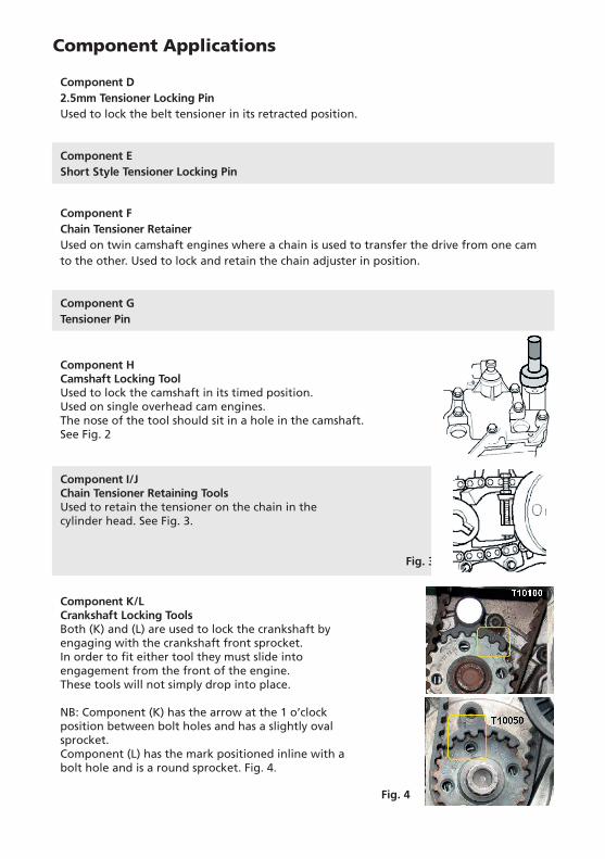
Component K/LCrankshaft Locking ToolsBoth (K) and (L) are used to lock the crankshaft by engaging with the crankshaft front sprocket. In order to fit either tool they must slide into engagement from the front of the engine. These tools will not simply drop into place.
NB: Component (K) has the arrow at the 1 o’clock position between bolt holes and has a slightly oval sprocket.Component (L) has the mark positioned inline with a bolt hole and is a round sprocket. Fig. 4.
Fig. 3
Fig. 4

Component Applications
Component MA pair of cam locking tools Used to lock the camshafts on the 1.2 twin cam engines. See Fig. 5
Component NA pair of Cambelt Locking Tools Used to lock the camshafts where a separate belt is used to transfer the drive from one shaft to the other. EG 1.4 petrol engines. See Fig. 6
Component OCamshaft and Diesel Pump Tools
Component PCamshaft Setting Bracket Allows the camshaft timing to be set by removing the vacuum pump and fitting the bracket into the slot of the camshaft as shown in Fig. 7
Component RDiesel injection pump locking pin Used where diesel pump is driven be a separate belt. See Fig 9.
Component QCrankshaft locking toolDesigned to lock the crankshaft by fitting in place of the crankshaft sensor and locking the flywheel in its timed position. Fig. 8
Fig. 5
Fig. 6
Fig. 7
Fig. 9
Fig. 8

Safety Precautions
• If the engine has been identified as an Interference engine, damage to the engine will occur if the timing belt has been damaged. A compresion check of all the cylinders should be taken before the cylinder head (s) are removed.
• Do not turn crankshaft or camshaft when the timing belt has been removed
• To make turning the engine easier, remove the spark plugs
• Observe all tightening torques
• Do not turn the engine using the camshaft or any other sprocket
• Disconnect the battery earth lead (Check Radio code is available)
• Do not use cleaning fluids on belts, sprockets or rollers
• Some toothed timing belts are not interchangeable. Check the replacement belt has the correct tooth profile
• Always mark the belt with the direction of running before removal
• Do not lever or force the belt onto its sprockets
• Check the ignition timing after the belt has been replaced.
• Do not use timing pins to lock the engine when slackening or tightening the crankshaft pulley bolts
• ALWAYS REFER TO A REPUTABLE MANUFACTURERS WORKSHOP MANUALWarning Incorrect or out of phase engine timing can result in damage to the valves. It is always recommended to turn the engine slowly, by hand, and to re-check the camshaft and crankshaft timing positions.
images courtesy of Autodatatm
Further information can be found at www.autodata.ltd.uk
Component STensioner Locking PlateUsed as shown in Fig.10
Component TTensioner Locking Pin
Fig. 10
Component Applications

www.kamasatools.com