eng energy saving hydraulic plaimm tb series€¦ · hydraulic type injection molding machine from...
TRANSCRIPT

ENG
TB seriesEnergy Saving Hydraulic PLAIMM

3
TB series
Model / Clamping Force Tie-Bar Clearance (HxV) Injection Unit [ Screw Diameter in mm ]25 28 30 35 40 45 50 55 60 65 70 75 80 90 100 105 115
TB 90S 360 x 360 O A B
TB 120S 410 x 410 O A B
TB 160S 460 x 460 O A B
TB 200S 510 x 510 O A B
TB 240S 560 x 560 O A B
TB 280S 610 x 610 O A B
TB 380S 710 x 710 O A B
TB 480S 830 x 830 O A B
TB 580S 910 x 910 O A B
TB 680S 1020 x 1020 O A B
TB 880S 1110 x 1110 O A B
TB series is the newly launched energy saving hydraulic type injection molding machine from WOOJIN PLAIMM equipped with servo pump system for optimum performance.
Energy Saving Hydraulic PLAIMM
- Center-press platen and brake motor in clamping unit has increased the accuracy & reproducibility.- Newly designed high-rigidity frame.- Main parts have new minimized and optimized design which made it possible to apply higher clamping force.- It assists in stabilizing the machine and reducing the noise during operation.
Oil circulation and oil cooling & filtering is divided separately maximizing the efficiency and durability of the machine. The injection unit is equipped with dual pull nozzle touch cylinder, Proportional/Integral/Differential valves & the low friction mechanism make it more precise & long-lasting.
Woojin PlaimmTB serise
OILCooling Water
Hydraulic oilconsumption
Cooling waterconsumption
Energyconsumption
60~80% savings 25% savings 15% savings
*Savings under standard conditions.
ControllerDual pull nozzle touch cylinder
Dual cylinder injection unit
Closed-loop system
Servo pump system
Hydraulic oil circulation system
Center press type
High rigidity frame
Brake motor for keeping clamping position
5
1.Servo Pump System
It saves the energy consumption up to 80%. It prevents high temperature in hydraulic oil. Thus, saving the oil cooling up to 25%. It also reduces the noise during machine operation.
Schematics of Servo Pump System
Controller
ServoMotorDriver
Servo Motor
Resolver
Pressure Sensor
P
P
UVW
Q
GearPump
DrT
ReliefValve
PS
2.Hydraulic Oil Circulation System - Oil-leakage protection - Increase durability - Better injection reproducibility - Reduce cooling & filtering time
Hydraulic oil rotation and oil cooling/filtering operate separately
maintaining constant conditions. It helps to improve reproducibility
and prevent the damages from excessive high temperature or
pressure.
In comparison, the normal oil rotation mechanism can bring the
contaminated oil back in the tank through oil cooling/filtering and
in the process, the filter can be blocked which can further lead to
excessively high temperature or oil leakage issues.
However the newly designed oil tank & rotation mechanism
separates the oil rotation from oil cooling/filtering through an
installed pump which makes sure that the contaminated oil and
the filtered clean oil have no contact with each other during the
machine operation.
Motor
Oil Tank
Oil CoolerOil Filter
Use
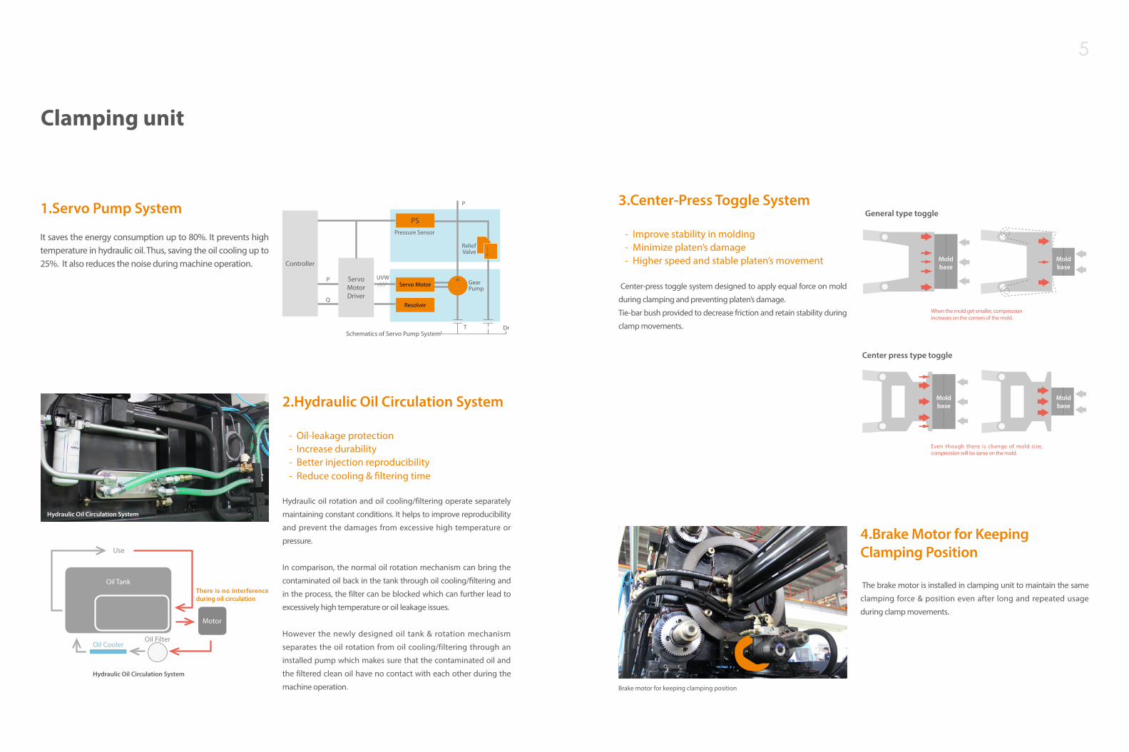
3.Center-Press Toggle System - Improve stability in molding - Minimize platen’s damage - Higher speed and stable platen’s movement
Center-press toggle system designed to apply equal force on mold
during clamping and preventing platen’s damage.
Tie-bar bush provided to decrease friction and retain stability during
clamp movements.
4.Brake Motor for Keeping Clamping Position The brake motor is installed in clamping unit to maintain the same
clamping force & position even after long and repeated usage
during clamp movements.
Brake motor for keeping clamping position
There is no interference during oil circulation
Hydraulic Oil Circulation System
Clamping unit
Hydraulic Oil Circulation System
Center press type toggle
General type toggle
When the mold get smaller, compression increases on the corners of the mold.
Even though there is change of mold size, compression will be same on the mold.
Mold base
Mold base
Mold base
Mold base
7
Injection unit
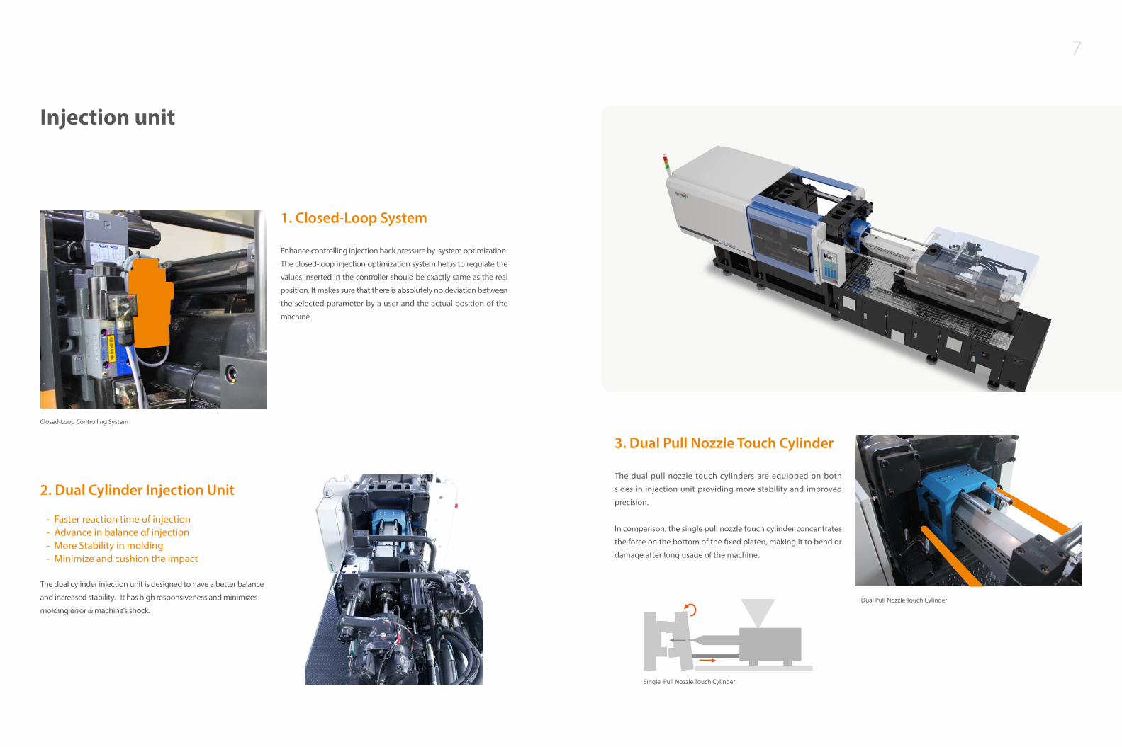
3. Dual Pull Nozzle Touch Cylinder The dual pull nozzle touch cylinders are equipped on both
sides in injection unit providing more stability and improved
precision.
In comparison, the single pull nozzle touch cylinder concentrates
the force on the bottom of the fixed platen, making it to bend or
damage after long usage of the machine.
Dual Pull Nozzle Touch Cylinder
Single Pull Nozzle Touch Cylinder
1. Closed-Loop System Enhance controlling injection back pressure by system optimization.
The closed-loop injection optimization system helps to regulate the
values inserted in the controller should be exactly same as the real
position. It makes sure that there is absolutely no deviation between
the selected parameter by a user and the actual position of the
machine.
2. Dual Cylinder Injection Unit
- Faster reaction time of injection - Advance in balance of injection - More Stability in molding - Minimize and cushion the impact
The dual cylinder injection unit is designed to have a better balance
and increased stability. It has high responsiveness and minimizes
molding error & machine’s shock.
Closed-Loop Controlling System

9
Controller(ES600)Applications A new type of high performance control system
ES600 maintains optimum machine condition at all times to produce high quality mold products thanks to the harmony between the multi-functional, high performance electronic control technology and the machine characteristics, which enables precision molding and provides stable system performance.
ES600 displays are in the form of graphs and pictures to facilitate user interface. The feed back control feature provides accurate operations based on configured conditions.
Controller technical data
Standard 10.4” TFT Color LCD
RS232(Mold Data, Fix Data, Sequence)/ CAN Comm.
Supports multiple languages (3 languages)
Temp Input: K or J Type
Supports CF memory ( up to 512MB): Mold Data, Shot Data, Screen Capture
Characteristics of ES600
- Multi-stage, precision control of each moving unit
- Simplified control using sensors on moving units
- Heating Cylinder zones: Default 7 Zones, Oil Temp 1 Zone
- Stores up to 100 Internal Mold Data sets
- Uses CF memory for External Mold Data
- Equipped with Robot Interface by default
- Can store Shot Data
- Displays Injection Speed and Pressure in graphic formats
Machine Status
Clamping
Injection & Holding Pressure
Nozzle & Material Change
Temperature
Mold Data
Product Control
Shot Data
Ejector & Robot
Setting Record
Alarm Record
Resin Type & Weekly Pre-heating
There are total of 21 functions such as machine status, clamping, injection & holding pressure, charging etc. displayed on a wide 10.4” screen in English, Chinese & Korean languages for user convenience with below 1ms of scan time.
TB seriseController System

11
Specification
1. Theoretical Injection Volume : Screw Diameter x Screw Stroke. 2. Minimum mold size must be over 60% of distance between tie-bar.3. This data based upon the 60Hz electricity frequency.4. Specifications can be changed for improvement without prior notice.
TB 90S TB 120S TB 160S TB 200S TB 240S TB 280S TB 380S TB 480S TB 580S TB 680S TB 880S
TB seriseSpecification
Injection UnitScrew & Barrel Type O A B O A B O A B O A B O A B
Screw Diameter mm 25 28 30 28 30 35 35 40 45 40 45 50 45 50 55
njection Pressure kg/cm2 3120 3000 2613 3000 2613 1920 3000 2297 1815 2297 1815 1470 2613 2117 1749
MPa 306 294 256 294 256 188 294 225 178 225 178 144 256 208 172
Theoretical Injection Volume cm3 98 123 141 123 141 192 212 276 350 276 350 432 413 510 618
Shot Weight (PS) g 90 113 130 113 130 177 195 255 322 255 322 398 381 470 569
Injection Rate cm3/s 62 60 69 60 69 94 105 137 173 137 169 209 147 182 220
Screw Stroke mm 140 140 140 200 200 200 220 220 220 220 220 220 260 260 260
Injection Speed mm/s 126 97 97 97 97 97 109 109 109 109 109 109 93 93 93
Plasticizing Capacity (PS) kg/h 26 35 42 35 42 63 68 97 132 97 132 175 101 134 173
Screw Rotation rpm 246 246 246 246 246 246 264 264 264 264 264 264 202 202 202
Clamping UnitClamping Force ton(kN) 90 (882) 120 (1176) 160 (1568) 200 (1960) 240 (2352)
Distance Between Tie-Bar (HxV) mm 360 x 360 410 x 410 460 x 460 510 x 510 560 x 560
Platen Size (HxV) mm 570 x 570 630 x 630 680 x 680 750 x 750 820 x 820
Opening Stroke mm 330 370 405 460 520
Daylight mm 680 770 855 960 1120
Min. Mold Height mm 140 150 180 180 200
Max. Mold Height mm 350 400 450 500 600
Ejector Force ton(kN) 3.4 (33.6) 3.4 (33.7) 4.2 (40.7) 4.2 (40.7) 5.8 (56.9)
Ejector Stroke mm 80 100 120 140 150
GeneralTotal Heat Capacity kW 6.4 6.4 9.2 11.1 13.2
Electric Motor Power Capacity kW 12.0 12.0 28.3 28.3 36.7
Total Electric Power Capacity kW 18.4 18.4 37.5 39.4 49.9
Total Oil Reservoir Capacity ℓ 200 200 270 270 330
Machine Weight ton 2.7 4.5 5.6 6.9 10.3
Machine Dimension (LxWxH) m 4.9 x 1.3 x 1.6 5.1 x 1.3 x 1.6 5.7 x 1.4 x 1.7 6.0 x 1.5 x1.8 6.7 x 1.5 x 1.9
Cooling Water Requirement ℓ/min 50 50 50 50 50
O A B O A B O A B O A B O A B O A B
50 55 60 65 70 75 65 70 80 70 80 90 80 90 105 95 105 115
2394 1979 1663 2020 1741 1517 2164 1866 1524 2351 1800 1422 2194 1733 1274 2269 1858 1549
235 194 163 198 171 149 212 183 149 231 177 139 215 170 125 223 182 152
550 665 792 1062 1231 1414 1278 1482 1935 1693 2212 2799 2488 3149 4286 4111 5022 6024
507 613 730 978 1135 1303 1177 1365 1783 1560 2038 2579 2293 2902 3950 3788 4628 5551
197 238 284 283 328 377 283 328 429 474 620 784 624 790 1075 763 932 1118
280 280 280 320 320 320 385 385 385 440 440 440 495 495 495 580 580 580
100 100 100 85 85 85 85 85 85 123 123 123 124 124 124 108 108 108
132 170 214 189 230 276 189 230 328 293 371 449 370 447 618 478 595 695
199 199 199 141 141 141 141 141 141 180 160 141 159 141 129 130 124 114
280 (2744) 380 (3724) 480 (4074) 580 (5684) 680 (6664) 880 (8624)
610 x 610 710 x 710 830 x 830 910 x 910 1020 x 1020 1110 x 1110
900 x 900 990 x 990 1220 x 1220 1340 x 1340 1500 x 1500 1630 x 1630
570 700 780 850 950 1200
1220 1450 1580 1800 2050 2400
250 300 350 400 450 500
650 750 800 950 1100 1200
5.8 (56.9) 8.8 (86.2) 13.7 (134.7) 15.2 (149.0) 21.2 (208.1) 24.7 (242.1)
170 200 200 225 255 255
15.5 24.3 24.3 28.2 35.4 48.8
36.7 56.3 56.3 93.0 (36.7 + 56.3) 112.6 (56.3 + 56.3) 129.7 (56.3 + 36.7 + 36.7)
52.2 80.6 80.6 121.2 148.0 178.5
385 535 535 900 1100 1300
12.2 16.8 16.8 33.0 43.0 55.0
7.3 x 1.6 x 1.9 8.1 x 1.8 x 2.1 9.0 x 2.0 x 2.1 10.2 x 2.3 x 2.2 10.8 x 2.6 x 2.5 13.0 x 2.6 x 2.6
70 70 70 70 100 100

13
570
4-Ø33
Ø77
340210200 200
200
210
390
630
210390630
570
340
210
200
4-Ø33
Ø77
690
4-Ø30
Ø75200280420540840
200100
280
420590920
200280490760
4-Ø33Ø90
200
280
490
760
249 140
200
280
420
540
840
400
200
100
280
420
590
920
400
12-Ø40Ø120
12-Ø40
Ø120
200100
2804005606901065
200
100
280
400
560
690
1065
200
341
100
2804007008101220
100
280
400
700
810
1220
12-Ø40
Ø130
2002804005607008901340
150100
200
280
400
560
700
890
1340
150
100
3608-Ø53
13-Ø33
200
420
400
700
1000
1500
150
100
399
200
420400
70010001500
150100
13-Ø33
8-Ø53
200
420
400
700
1090
1630
150
100
394
200
420400
70010901630
150100
13-Ø33
8-Ø53
4-Ø28
169
200280444690
200
280
444
Ø33
Ø90
179140
Platen DimensionMachine Dimension
90 ton
200 ton 240 ton 280 ton
380 ton 480 ton 580 ton
680 ton 880 ton
120 ton 160 ton
A B
CD
6-M E Tap
R N
L M
G
FH 4-M I Tap
J K
A B C D E F G Ø H I Ø J Ø K L M N
TB 90S 90 90 57 40 12 100 100 85 12 100 2.5 100 25 9.5
TB 120S 105 105 47 40 12 100 100 85 12 100 2.5 100 30 9.5
TB 160S 125 125 62 70 14 120 120 95 12 100 2.5 100 30 9.5
TB 200S 150 150 62 70 14 120 120 95 12 100 3.0 50 30 12.5
TB 240S 150 150 70 70 14 120 120 100 12 120 3.0 50 40 12.5
TB 280S 150 150 68 70 14 120 120 100 12 120 3.5 50 40 12.5
TB 380S 190 190 67 100 20 127 127 90 12 120 3.5 50 45 12.5
TB 480S 210 210 67 100 20 127 127 68 12 120 4.0 50 40 19.0
TB 580S 210 210 67 150 20 165 165 78 12 200 5.0 50 60 19.0
TB 680S 280 280 84 230 20 165 165 88 12 200 5.0 50 60 19.0
자동취출기 설치도 Hopper 설치도 Nozzle 제원
E
G
C AD
J K
B
FH
IA B C D E F G H I J K
TB 90S 4200 4850 860 1284 1190 1385 2160 1570 1475 608 588
TB 120S 4425 5107 910 1334 1205 1400 2352 1617 1530 667 667
TB 160S 4955 5698 940 1384 1225 1503 2613 1676 7585 702 682
TB 200S 5025 5942 980 1474 1275 1478 2862 1760 1665 747 727
TB 240S 5710 6634 1084 1518 1348 1578 3274 1870 1778 769 749
TB 280S 6135 7252 1170 1604 1360 1610 3602 1927 1825 812 792
TB 380S 6895 8119 1340 1740 1375 1620 4244 2032 1920 880 860
TB 480S 7790 9023 1440 2004 1373 1618 4738 2105 1993 1069 935
TB 580S 8885 10159 1580 2324 1480 1650 5430 2212 2160 1235 1089
TB seriesMachine dimension

15
INJECTION UNIT CLAMPING UNIT GENERAL
StandardInjection process control stage (Speed / Pressure) 6 Mold opening speed & pressure
control stage 5 Molding data memor y capacity (Internal / External) 1000/usb
Holding process control stage (Speed / Pressure) 3 Mold closing speed & pressure
control stage 5 Alarm history display & saving S
Charging process control stage (Speed / Pressure) 4 Ejector speed & pressure control
stage 2 Record of value changing S
Back pressure control stage 4 Clamping position display S Statistical function S
Suck back control (Before) 1 Automatic mold height adjustment S I/O circuit display S
Suck back control (After) 1 Ejector position display S Multi language display – Korean / English / Chinese S
Injection position display S Hydraulic core puller 1 stage S Robot interlock circuit S
Injection speed graph display S Air blow off unit S Hydraulic oil level alarm S
Back pressure closed-loop S Safety device(Electric / Hydraulic) S Hydraulic oil temperature over alarm S
Cushion amount display & alarm S Hydraulic oil heating control device S
Screw RPM display S Reserved injection mold number and alarm S
Auto purge circuit S Hopper throat temperature control device S
Screw cold start prevention device S Automatic lubricating device S
Pre-heating timer (weekly) S Shot data file saving (External) S
Heater temperature abnormal display S Product chute S
Cylinder temperature keeping mode S Leveling pads S
Valve gate 1 stage S Maintenance tools S
Spare parts S
Electrical outlet (5 socket)-2set S
Option
Injection pressure graph display O Unscrewing device O Robot interlock interface (Euromap 12 / SPI) O
Shut-off Nozzle(Hydraulic type, Spring type, Air pressure type )
O Daylight extension O Hopper moving device O
Screw & Barrel(Anti-wear or Anti-wear/corrosion) O Auto safety door open / close device O
SB screw O Hydraulic oil cleaner O
Lubricating oil recycling device O
Auto clamps(QDC) O
Insulation plate for mold O
Electricity (220V, 380V, 440V, 480V) O
Electrical outlet (5socket)-addition 2set O
Option Lists
Option &Global Network
S : Standard O : Option
Global Network
WOOJIN PLAIMM USA
WOOJIN PLAIMM Mexico
WOOJIN PLAIMM Japan
WOOJIN PLAIMM China
WOOJIN PLAIMM Austria
L.A Tel +1-951-734-7890(Ext.102)Fax +1-951-734-7891E-mail [email protected]
Chicago Tel +1-951-734-7890(Ext.201)E-mail [email protected]
Tel +81-52-919-7775 Fax +81-52-919-7776E-mail [email protected]
Tel +52-81-1090-8726E-mail [email protected]
WOOJIN PLAIMM KoreaTel +82-43-540-9000 E-mail [email protected]
Ningbo Tel +86-574-8680-6088Fax +86-574-8680-6077E-mail [email protected]
Guangdong Tel +86-769-8352-5307Fax +86-769-8222-5030
Shandong Tel +86-535-671-2246Fax +86-535-671-7313
Suzhou Tel +86-512-6565-0531Fax +86-512-6565-0530
Tianjin Tel +86-22-2388-2103Fax +86-22-2388-2103

www.woojinplaimm.com
Printed in Korea. September2014 - TB_EN02